Embed Size (px)
Citation preview
————————————————————————
1
FGLD-SFGLD /2 ENGINES / 55
NATURAL GAS 1500 RPM
IRAN
————————————————————————
2
PRESENTATION COGENERATION ENGINES AND SYSTEMS GUASCOR, S.A. is the company within the group that for more 30 years has specialized in using its own technology to manufacture reciprocating gas and diesel engines, applied to marine propulsion and auxiliary equipment, cogeneration and trigeneration plants and containerised sets for power generation.
INSTALLATIONS GUASCOR S.A. has modern installations covering a built-up area of 5,000 m2. The manufacturing plant is equipped with the latest generation on production systems, control laboratories, diagnosis and testing equipment, test benches, etc. GUASCOR I + D (the R & D Centre) has 22 engine test benches, equipped with hydraulic brakes, alternators, resistance cells, as well as an electronics laboratory and an engine instrumentation and assembly workshop. The facilities provide systems for studies and analysis of combustion processes, emission measurement on gas and diesel engines, evaluation of engine behaviour and endurance tests, which determine maintenance periods and procedures, behaviour tests on components, lubricating oils, etc. CONTINUOUS IMPROVEMENT GUASCOR S.A. applies a strict policy for research and development, training and continuous improvement which guarantees maximum quality for its products and satisfaction for its customers
Cert. 954375
DESIGN GUASCOR S.A. has an engineering department equipped with advanced engine modeling, calculation and design systems. The research and development which is carried out in our TECHNOLOGICAL CENTRE of Vitoria (GUASCOR I + D), along with the use of the most modern technologies that can be applied to engines, are the basic premise to achieve one of our main goals: The construction of reliable, high power, low consumption, environmentally friendly engines which are easy to operate and maintain.
ACTIVITIES
Gas and Diesel Engines
Cogeneration systems
Marine engines
Modular power plants
QUALITY GUASCOR S.A. holds the Quality Assurance Certificate issued by Lloyd's Register Quality Assurance, which guarantees that the quality assurance system applied by GUASCOR S.A. to the design, machining, assembly installation and after-sales service for its gas and diesel engines, marine propulsion and auxiliary systems, energy and cogeneration systems, complies with the ISO 9001 standard.

————————————————————————
3
DIRECTORIO GUASCOR offices and distributors are alongside the world:
GUASCOR DISTRIBUTORS AROUND THE WORLD ARGENTINA BANGLADESH BENELUX BRAZIL DENMARK ENGLAND FRANCE GERMANY
GREECE HOLLAND INDIA INDONESIA ITALY KOREA MOROCCO PAKISTAN
PORTUGAL SENEGAL SINGAPORE SPAIN THAILAND TUNISIA TURKEY U.S.A.
Barrio de Oikia, 44 - 20759 Zumaia. Gipuzkoa. Spain
P.O. Box 30. Tel.: 34 943 865 200. Fax 34 943 865 210 www.guascor.com
INTERNATIONAL OFFICES GUASCOR ARGENTINA GUASCOR BRAZIL GUASCOR INDIA GUASCOR ITALY GUASCOR MOROCCO GUASCOR USA INTERNATIONAL
NATIONAL OFFICES GUASCOR BARCELONA GUASCOR GALICIA GUASCOR MADRID GUASCOR SEVILLA GUASCOR VALENCIA
————————————————————————
4
ÍNDICE 0.- OFFER REQUISITION, INITIAL DATA AND PREMISES 1.- TECHNICAL DATA
1.1.- Module Data. 1.2.- Engine Data. 1.3.- Alternator Data.
2.- SCOPE OF SUPPLY
2.1.- Basic Module. 2.2.- Accessories. 2.3.- Control Panel. 2.4.- Power Panel.
3.- ECONOMICAL OFFER
3.1.- Supply Conditions.
4.- ANNEX
Operating Condition Factors. Guascor gas engines fuel specification. Engine Thermal Balances
————————————————————————
5
0.- OFFER REQUISITION, INITIAL DATA AND PREMISES FIRST
This offer has been required by Alternatif A.S. , company based in Tehran (IRAN) .
The offer requisition is referred to the supply of gas engines for generating purposes by using natural gas. The required power range is:
1. 500 kW 2. 600 kW 3. 800 kW 4. 1000 kW 5. 2000 kW
The request of the quotation for GUASCOR generating plant was sent us by e-mail the 18th of January 2005. SECOND To elaborate the offer we have taken into account the following items: GAS COMPOSITION We have received two gas composition analysis with the following values: LOCATION AND DATE 56 Inch Line Gas 12-Nov-04 Metering XXX Gas Fax 18/01/2005 METHANE (%vol) 88,35 98,39 ETANE (%vol) 3,88 0,66 PROPANE (%vol) 1,17 0,07 BUTANES (%vol) 0,57 0,08 PENTANES (%vol) 0,23 0,06 C6+ (%vol) 0,21 0,13 NITROGEN (%vol) 5,50 0,48 CARBON DIOXIDE (%vol) 0,09 0,13 HYDROGEN SULFIDE (ppm) 0,76 1,3 DENSITY (Kg/Nm3) 0,811 0,733 LHV (KJ/Kg) 45314 49443 METHANE NUMBER 77,9 93,1 GENERAL SUBJECTS We are supposing that the required power is electrical power and the required grid frequency/voltage is 50 Hz/400 VAC. We are offering: natural gas generating sets (engine-alternator-bed frame), with accessories: water pumps, cooling circuits with radiators, gas ramp, lube oil tank, control panel and power panel. THIRD GUASCOR will guarantee the operation of the engines if the composition of the fuel gas matches with the technical specification we have fixed in our technical document called “Guascor gas engines fuel specification G-30-017e” (annex 2). FOURTH On the basis of the received data we are offering all our FGLD/SFGLD gas engine series to be adapted at the required power by using one or two engines: FGLD180 FGLD240 FGLD360 FGLD480
SFGLD180 SFGLD240 SFGLD360 SFGLD480 SFGLD560
————————————————————————
6
1.- TECHNICAL DATA
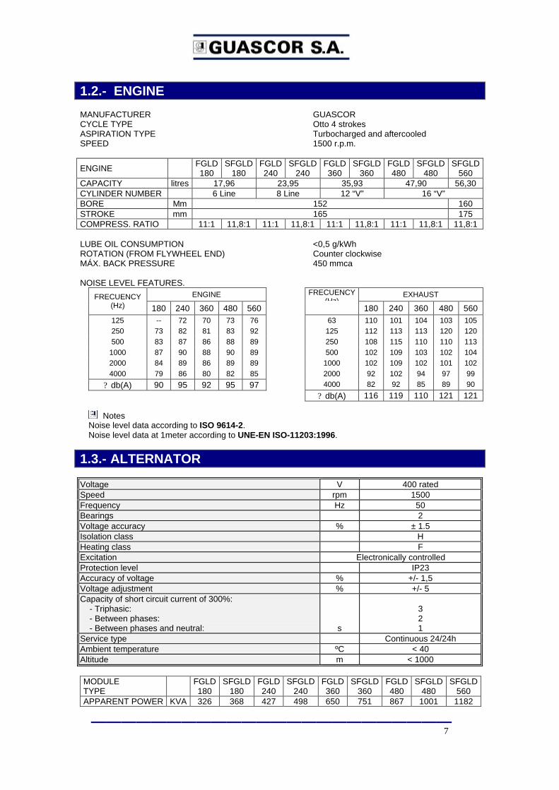
1.1.- MODULE ENGINE TYPE Turbocharged and aftercooled FUEL Natural Gas SPEED 1500 rpm (50Hz) WATER COOLING Two circuits (90/55ºC) by radiator ENGINE FGLD
180 SFGLD
180 FGLD 240
SFGLD 240
FGLD 360
SFGLD 360
FGLD 480
SFGLD 480
SFGLD 560
Brake Power kWb 275 315 360 419 550 630 725 838 985
Water Pumps & Radiator KWb 14 15 17 19 24 27 30 34 39
Electrical Power kWe *
251 286 331 387 506 583 674 779 919
Mechanical Efficiency % 40,1 41,9 39,0 41,0 40,0 41,3 39,2 41,1 41,3
Electrical Efficiency %*
36,5 38,0 35,8 37,8 36,8 38,2 36,4 38,2 38,5
Notes *Considering water pumps and water cooling radiator driven by engine crankshaft (/2 Version). Alternator efficiency cos Phi = 1 See Annex 3 Engine Thermal Balances. According to ISO 3046 and ISO 8528 See Annex 1 Operating Condition Factors. See Annex 2 Guascor gas engines fuel specification. SERVICE Continuous 24/24h EMISSIONS No limits, considered 2 TA-Luft carburetion point DIMENSIONS AND WEIGHT
MÓDULE
FGLD 180
SFGLD 180
FGLD 240
SFGLD240
FGLD 360
SFGLD 360
FGLD 480
SFGLD 480
SFGLD 560
Length A mm 2.774 3.024 3.408 3461 3.580 3.830 4.146 4.396 4.669 Width B mm 1.226 1.226 1.235 1300 1.689 1.689 1.690 1.690 1.693 Height C mm 2.210 2.210 2.268 2268 2.432 2.432 2.557 2.557 2.560 Weight kg 3.860 3.885 4.770 4870 6.502 6.527 8.400 8.425 9.780
Notes The dimensions and weights are approximate and can be different depending on the chosen alternator.
————————————————————————
7
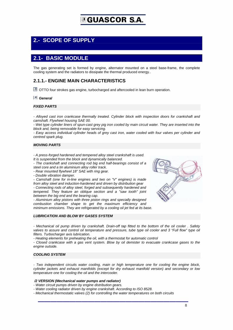
1.2.- ENGINE MANUFACTURER GUASCOR CYCLE TYPE Otto 4 strokes ASPIRATION TYPE Turbocharged and aftercooled SPEED 1500 r.p.m.
ENGINE FGLD 180
SFGLD 180
FGLD 240
SFGLD 240
FGLD 360
SFGLD 360
FGLD 480
SFGLD 480
SFGLD 560
CAPACITY litres 17,96 23,95 35,93 47,90 56,30 CYLINDER NUMBER 6 Line 8 Line 12 “V” 16 “V” BORE Mm 152 160 STROKE mm 165 175 COMPRESS. RATIO 11:1 11,8:1 11:1 11,8:1 11:1 11,8:1 11:1 11,8:1 11,8:1 LUBE OIL CONSUMPTION <0,5 g/kWh ROTATION (FROM FLYWHEEL END) Counter clockwise MÁX. BACK PRESSURE 450 mmca NOISE LEVEL FEATURES.
ENGINE FRECUENCY (Hz) 180 240 360 480 560 125 -- 72 70 73 76 250 73 82 81 83 92 500 83 87 86 88 89
1000 87 90 88 90 89 2000 84 89 86 89 89 4000 79 86 80 82 85
? db(A) 90 95 92 95 97
EXHAUST FRECUENCY (Hz)
180 240 360 480 560 63 110 101 104 103 105 125 112 113 113 120 120 250 108 115 110 110 113 500 102 109 103 102 104
1000 102 109 102 101 102 2000 92 102 94 97 99 4000 82 92 85 89 90
? db(A) 116 119 110 121 121
Notes Noise level data according to ISO 9614-2. Noise level data at 1meter according to UNE-EN ISO-11203:1996.
1.3.- ALTERNATOR Voltage V 400 rated Speed rpm 1500 Frequency Hz 50 Bearings 2 Voltage accuracy % ± 1.5 Isolation class H Heating class F Excitation Electronically controlled Protection level IP23 Accuracy of voltage % +/- 1,5 Voltage adjustment % +/- 5 Capacity of short circuit current of 300%: - Triphasic: - Between phases: - Between phases and neutral:
s
3 2 1
Service type Continuous 24/24h Ambient temperature ºC < 40 Altitude m < 1000 MODULE TYPE FGLD
180 SFGLD
180 FGLD 240
SFGLD 240
FGLD 360
SFGLD 360
FGLD 480
SFGLD 480
SFGLD 560
APPARENT POWER KVA 326 368 427 498 650 751 867 1001 1182
————————————————————————
8
2.- SCOPE OF SUPPLY
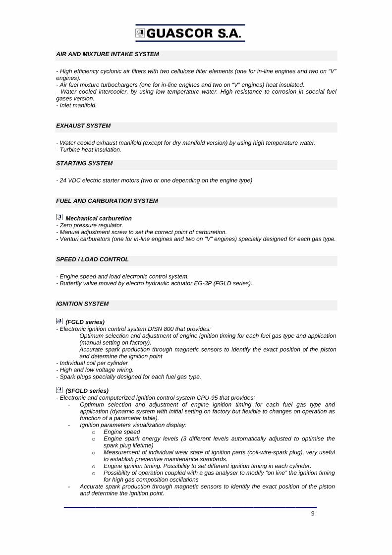
2.1- BASIC MODULE The gas generating set is formed by engine, alternator mounted on a steel base-frame, the complete cooling system and the radiators to dissipate the thermal produced energy.. 2.1.1.- ENGINE MAIN CHARACTERISTICS
OTTO four strokes gas engine, turbocharged and aftercooled in lean burn operation.
General FIXED PARTS
- Alloyed cast iron crankcase thermally treated. Cylinder block with inspection doors for crankshaft and camshaft. Flywheel housing SAE 00. - Wet type cylinder liners of spun-cast grey pig iron cooled by main circuit water. They are inserted into the block and, being removable for easy servicing. - Easy access individual cylinder heads of grey cast iron, water cooled with four valves per cylinder and centred spark plug. MOVING PARTS
- A press-forged hardened and tempered alloy steel crankshaft is used. It is suspended from the block and dynamically balanced. - The crankshaft and connecting rod big end half-bearings consist of a steel core and a tin aluminium alloy roller track. - Rear mounted flywheel 18” SAE with ring gear. - Double vibration damper. - Camshaft (one for in-line engines and two on “V” engines) is made from alloy steel and induction-hardened and driven by distribution gear - Connecting rods of alloy steel, forged and subsequently hardened and tempered. They feature an oblique section and a "saw tooth" joint between the big end and the bearing cap. - Aluminium alloy pistons with three piston rings and specially designed combustion chamber shape to get the maximum efficiency and minimum emissions. They are refrigerated by a cooling oil jet fed at its base. LUBRICATION AND BLOW BY GASES SYSTEM
- Mechanical oil pump driven by crankshaft. Drain-off tap fitted to the bottom of the oil cooler . Safety valves to assure and control oil temperature and pressure, tube type oil cooler and 3 “Full flow” type oil filters. Turbocharger axis lubrication. - Heating elements for preheating the oil, with a thermostat for automatic control - Closed crankcase with a gas vent system. Blow by oil demister to evacuate crankcase gases to the engine outside. COOLING SYSTEM
- Two independent circuits water cooling, main or high temperature one for cooling the engine block, cylinder jackets and exhaust manifolds (except for dry exhaust manifold version) and secondary or low temperature one for cooling the oil and the intercooler. /2 VERSION (Mechanical water pumps and radiator) - Water circuit pumps driven by engine distribution gears. - Water cooling radiator driven by engine crankshaft. According to ISO 8528. - Mechanical thermostatic valves (2) for controlling the water temperatures on both circuits
————————————————————————
9
AIR AND MIXTURE INTAKE SYSTEM
- High efficiency cyclonic air filters with two cellulose filter elements (one for in-line engines and two on “V” engines). - Air fuel mixture turbochargers (one for in-line engines and two on “V” engines) heat insulated. - Water cooled intercooler, by using low temperature water. High resistance to corrosion in special fuel gases version. - Inlet manifold. EXHAUST SYSTEM
- Water cooled exhaust manifold (except for dry manifold version) by using high temperature water. - Turbine heat insulation. STARTING SYSTEM
- 24 VDC electric starter motors (two or one depending on the engine type) FUEL AND CARBURATION SYSTEM
Mechanical carburetion
- Zero pressure regulator. - Manual adjustment screw to set the correct point of carburetion. - Venturi carburetors (one for in-line engines and two on “V” engines) specially designed for each gas type. SPEED / LOAD CONTROL
- Engine speed and load electronic control system. - Butterfly valve moved by electro hydraulic actuator EG-3P (FGLD series). IGNITION SYSTEM
(FGLD series)
- Electronic ignition control system DISN 800 that provides: Optimum selection and adjustment of engine ignition timing for each fuel gas type and application (manual setting on factory). Accurate spark production through magnetic sensors to identify the exact position of the piston and determine the ignition point
- Individual coil per cylinder - High and low voltage wiring. - Spark plugs specially designed for each fuel gas type.
(SFGLD series) - Electronic and computerized ignition control system CPU-95 that provides:
- Optimum selection and adjustment of engine ignition timing for each fuel gas type and application (dynamic system with initial setting on factory but flexible to changes on operation as function of a parameter table).
- Ignition parameters visualization display: o Engine speed o Engine spark energy levels (3 different levels automatically adjusted to optimise the
spark plug lifetime) o Measurement of individual wear state of ignition parts (coil-wire-spark plug), very useful
to establish preventive maintenance standards. o Engine ignition timing. Possibility to set different ignition timing in each cylinder. o Possibility of operation coupled with a gas analyser to modify “on line” the ignition timing
for high gas composition oscillations - Accurate spark production through magnetic sensors to identify the exact position of the piston
and determine the ignition point.
————————————————————————
10
- Individual coil per cylinder - High and low voltage wiring. - Spark plugs specially designed for each fuel gas type. - Piezoelectric sensors for detonation detecting in each cylinder - DETCON central control unit programmed with the particular detonation wave maps of the engine. This allows the timing to be adjusted in combination with the CPU95 unit via the PLC, as well as reducing power when running in parallel with the main grid. INSTRUMENTATION PANEL ON ENGINE / SAFETY SENSORS
- Control panel fitted on engine with a standard 6-gauge panel measuring:
. Main cooling water temperature.
. Secondary cooling water temperature
. Lube oil pressure.
. Lube oil temperature
. Intake manifold mixture temperature.
. Intake manifold mixture pressure - Safety sensors. . High main cooling water temperature . Air filter saturation visual indicator.
. Low and high lube oil pressure . Overspeed . High intake manifold mixture temperature . High and low oil level . High lube oil temperature ( “V” engines) . Lube oil filters saturation (“V” engines) - Sensors wiring right up to a junction box on the engine equipped with an emergency shutdown button 2.1.2.- ALTERNATOR MAIN CHARACTERISTICS - Synchronous alternator, self regulated, brushless. - Double bearing. - Self ventilated. - Electronic voltage adjustment system for synchronisation purposes and controlling the power factor when running parallel with the grid supply (only if necessary). - Directly flanged to engines flywheel housing. - The Alternators are manufactured fulfilling the following International norms: I.E.C / U.T.E. / U.D.E. / B.S.S. / NEMA / CSA. 2.1.3.- BEDFRAME. - Steel high rigidity base-frame electro welded, common engine and alternator.. - Elastic foundations “Metaelastic” for single stage resilient isolation.
————————————————————————
mail : [email protected]
11
2.2.- ACCESSORIES
Air filters. - Optional: Air filter saturation electrical switch (alarm). Not included in this offer. - Optional: Cyclonic air prefilter for high dust concentration ambient. Not included in this offer.
Flexibles. - Lube oil flexible - Water main circuit flexible - Water secondary circuit flexible - Exhaust flexible - Gas line flexible
External lube oil system - Electric pump and a set of valves for pre-lube, filling or emptying the crankcase - Automatic oil level control, with an automatic sump top-up system. - Optional: 300 litres oil tank to supply new oil to the engine. Not included in this offer. - Optional: Closed crankcase gas ventilation system. Not included in this offer.
Gas ramp.
- Manual shut-off valve. - Gas filter. - Pressure regulator - Double solenoid valve train. - Electronic inter-valve gas leak detector - Pressure gauges (2). - Pressure switches (2) for activating high and low pressure alarms
Exhaust system
- Exhaust “Y” collector to join the two exhaust outlets in case of “V” engines. - Exhaust pyrometer or “K” type thermocouples for the exhaust temperatures - Exhaust flexible connection. - Optional: Oxidative catalyst converter to reduce CO and NMHC emissions. Not included in this offer - 30-dB attenuation exhaust silencer without spark arrestor.
Starting system
- Optional: pneumatic starter for compressed air at 30 bar. Not included in this offer - Starting batteries including:
- Batteries support on bedframe. - Pb – PbO2 230 Ah, 12+12 VDC double batteries in series with manual cut-off switch.
Cooling system
- Optional: Automatic water preheating system. Not included in this offer.
Electrical wiring to junction boxes. - 24VDC and 220/380VAC independent electrical boxes. - Wiring with special silicone leads covered by fibre-glass and stainless steel twist with high resistance to aggressive ambient.
Elastic fittings
-6, 8, or10 elastic fittings between bedframe and ground depending on engine type.
————————————————————————
12
Others
- Painting - Documentation.
- Installation manual. - Control panel electrical drawings. - Maintenance manual - CE declaration. - Spare parts book.
- Factory tests. - Module commissioning. - Commissioning lube oil barrel.
Commissioning standard spare part kit.
Commissioning standard toolbox kit.
2.3.- CONTROL PANEL The control and protection panel can be used to work in parallel or island generation. It includes a synchronisation and grid protection panel that can be used for up to four modules simultaneously. 2.3.1.- FUNCTIONS CARRIED OUT BY THE CONTROL PANEL
Complete control, both manually and assisted, over the operation of the Guascor module. Manual and automatic operation of the genset auxiliary equipment supplied by Guascor. Automatic start-up based on electricity tariff rates. Continuous protection for the engine and alternator, with shutdown function in the event
of alarms. Automatic synchronisation for the genset to the grid supply or other groups. PLC control over power generated by the genset based on specified power settings. Display of any alarms produced and a record of previous alarms shown on the operator
control screen (TFT touch screen). Display of basic variables for both the engine and accessories; temperatures and
pressures shown directly on the operator terminal. Visual and acoustic status reports (operation – alarms).
2.3.2.- ENGINE ELECTRONIC CONTROLS ON THE CONTROL PANEL. - Unit for controlling speed and (SFGLD series) carburetion and misfiring. - Unit for controlling load distribution (PLC). - Automatic synchronization unit (SPM-A).
Description of how these elements work:
The control system takes charge of the engine to ensure that it operates completely automatically, to do this it carries out the following actions:
?? It controls the speed of the engine so that the frequency at which the generator turns matches exactly with the desired frequency (50/60Hz), independently of the electrical power being generated.
?? When running in parallel, the control system regulates the speed of the engine so that when the alternator is about to be synchronised the frequency and phase are the same as that of the main grid, at which point it sends out a signal to close the corresponding circuit breaker
?? When the genset is working in parallel with the main grid it sets the power based on the user requirements.
————————————————————————
13
Synchronizer This device analyses voltages from the generator and the bus bar, comparing their phase, frequency and amplitude. It then sends a control signal to the speed control device in order to modify the speed of the genset so that the voltages from the generator and the bus bar, to which it will be coupled, match in frequency and phase. As soon as it gets within synchronisation limits it sends out a signal to close the main circuit breaker of the genset.
PLC load control
A signal, proportional to the real electrical power being generated, is received via a power converter. It compares this signal to a pre-set reference and as a result of this comparison it sends a control signal to the speed governor, modifying the speed slightly and ensuring that the generator produces the right amount of power.
Speed control
This device receives a magnetic pick-up signal from the engine toothed ring gear, the frequency of which is proportional to the speed of the ring. It then compares this signal to a pre-set speed reference and instructs the actuator to regulate the flow of air-fuel mixture.
2.3.3.- DESCRIPTION OF THE CONTROL PANEL. - The control panel cabinets are built in a metallic case where all the components are installed. - The unitary dimensions are 2100 (height) x 800 (length) x 800 (width). - Individual automatic door-activated lighting. - Thermostatically controlled heat extractor operating via the air inlet filter and fan.
Measuring equipment
- 1 Multimeter for electrical parameters. 24VDC model, three displays and RS-485 port - 1 Power converter to provide 4-20 mA - 1 Class 1 active energy meter
Protection equipment
- 1 three-phase sensor for minimum and maximum voltages (ANSI functions 27/59) - 1 three-phase sensor for minimum and maximum frequency (ANSI functions 81m/81M) - 1 Overload and short-circuit sensor (ANSI functions 50/51) - 1 Reverse power detector (ANSI function 32). This is software implemented - 1 Two levels speed relay (to detect engine started and overspeed) - 1 Alarm module specifically for the engine - 1 Alarm module for the genset auxiliary services. - Dual emergency shut-down (both on the control panel and the genset itself)
?? Shuts off the fuel supply ?? Opens the main breaker ?? Reports to the PLC
Control equipment
- 1 electronic unit for controlling speed. - 1 PLC load control + converter - 1 Control unit for the alternator excitation circuit
Other equipment for the set
- 24V, 40A electronic battery charger, with minimum voltage sensor (ANSI 27), voltmeter and ammeter - Control for the pre-lube pump with selector for automatic, manual or OFF positions - Control for the dual circuit radiator fans, with selector for automatic, manual or OFF positions - Control to start and stop the genset - Control for the resistors to preheat the oil, with thermostatic control and disconnection switch - Basic engine parameters: Left / Right exhaust temperature, water temperature, oil temperature, oil pressure and power generated, all displayed on the colour touch screen. - Potential free contact switches for indicating genset status: Genset running, genset running in parallel with main grid, cooling system on, genset warning siren, general alarm. - Control for the gas ramp with electronic leak detection - Control for the engine electronic ignition system
————————————————————————
14
Equipment to control and protect the genset on grid
Protection equipment
- 1 three-phase relay for minimum and maximum voltages (ANSI functions 27/59) - 1 three-phase relay for minimum and maximum frequency (ANSI functions 81m/81M) - 1 voltage micro cuts relay for changes in the voltage speed vector (ANSI function 78)
Control equipment
- 1 programmable logic controller, PLC, Telemecanique TSX 57 or similar - 1 operator terminal with large sized colour touch-screen - 1 WOODWARD SyG electronic synchroniser - 1 Synchronoscope 360 º
Miscellaneous equipment
- Thermostatically controlled heat extractor operating via the air inlet filter and fan - Automatic door-activated lighting. Special low electromagnetic emission lamp suitable for use close to PLCs and control systems.
2.4.- POWER PANEL This is used to connect or disconnect the alternator to or from the main grid and/or load. The panel houses the power switch and complementary elements. Each unit dimensions are 2100 (height) x 800 (width) x 800 (depth). The power panel is basically comprised of a 4 pole bus bar and a four pole automatic circuit breaker. The detailed components are:
*1 circuit breaker MASTERPACT MERLIN GERIN metal chassis automatic four pole, at rated current and short-circuit current, fixed assembly, equipped with motor, closing coil and trip coil for minimum voltage.
*3 current transformers, type rated current/5A, for protection, class 5P10
*3 current transformers, type rated current/5A, for measurement, Class 0.5
*1 Copper bus bar, suitably sized for rated current, insulated in coloured plastic insulation for identifying the phases. *1 Thermostatically controlled heat extractor operating via the air inlet filter and fan
————————————————————————
Email : [email protected]
15
3.1.- SUPPLY CONDITIONS
PAYMENT TERMS
- Irrevocable and Confirmed L/C payable at sight by a first class European bank
DELIVERY DATE 12 to 16 working weeks EXW after:
?? Order receipt ?? Technical and commercial items have been completely clarified ?? Down payment confirmation
OFFER VALIDITY - 3 months
WARRANTY - 12 months from commissioning or 18 months from delivery, whichever comes earlier
NOT INCLUDED - Transport and download - Mechanical and electrical assembly external to the genset - Instrumentation not described in this offer - Homologations, licences, registration or all kind of government or local authorizations or duties - Wiring from alternator to the panels - V.A.T. - All that has not been specified on this offer.
————————————————————————
16
FGLD-SFGLD /2 ENGINES / 55
NATURAL GAS 1500 RPM
IRAN
ANNEX 1
OPERATING CONDITION FACTORS
————————————————————————
17
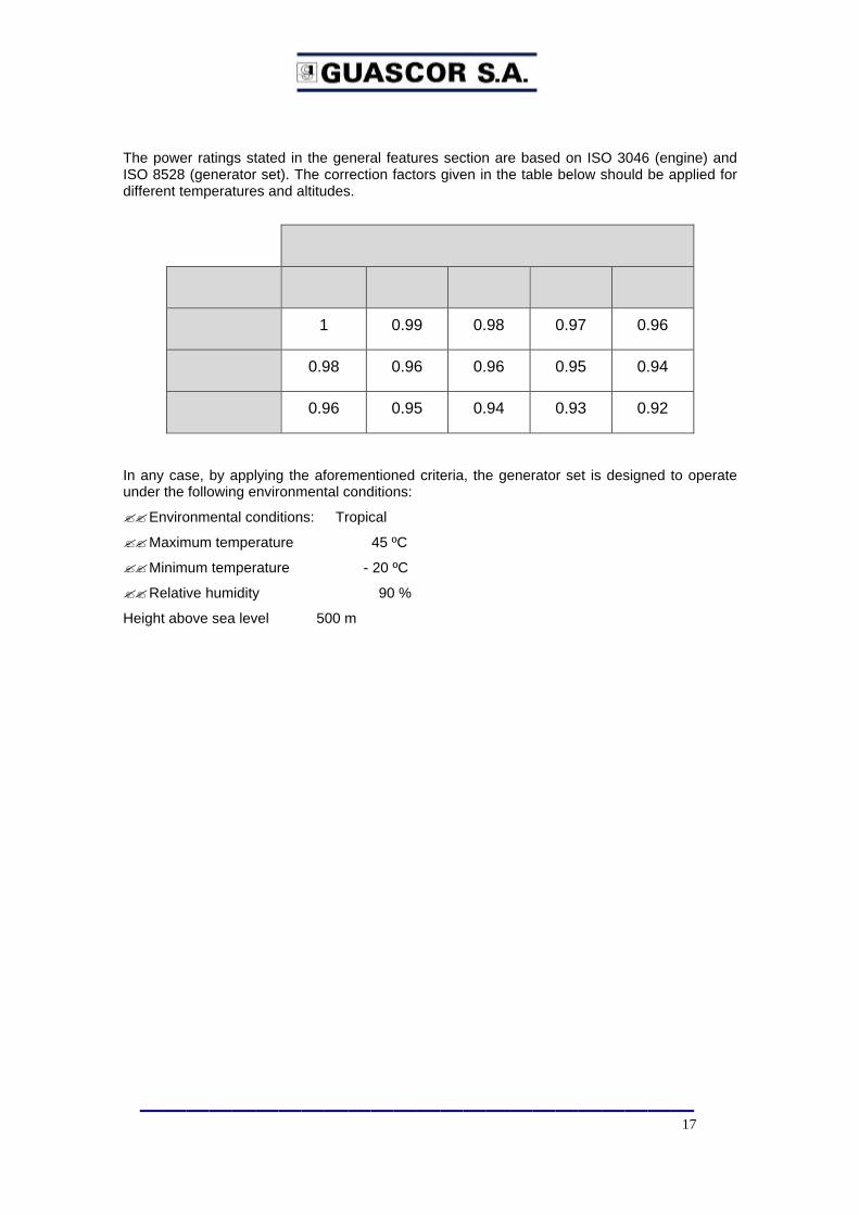
The power ratings stated in the general features section are based on ISO 3046 (engine) and ISO 8528 (generator set). The correction factors given in the table below should be applied for different temperatures and altitudes.
Engine Air Temperature (ºC)
Altitude a.s.l. 25 30 35 40 45
500 1 0.99 0.98 0.97 0.96
800 0.98 0.96 0.96 0.95 0.94
1100 0.96 0.95 0.94 0.93 0.92
In any case, by applying the aforementioned criteria, the generator set is designed to operate under the following environmental conditions:
??Environmental conditions: Tropical
??Maximum temperature 45 ºC
??Minimum temperature - 20 ºC
??Relative humidity 90 %
Height above sea level 500 m

————————————————————————
18
FGLD-SFGLD /2 ENGINES / 55
NATURAL GAS 1500 RPM
IRAN
ANNEX 2
GUASCOR GAS ENGINES FUEL SPECIFICATION G-30-017e
CHAPTER
30
FUEL CIRCUIT PRODUCT INFORMATION
G-30-017e FUEL SPECIFICATIONS
FOR GUASCOR GAS ENGINES
DATE
03-03-03 INDEX
1/8G-30-017e
K
1. - AIM This product datasheet defines the conditions a gas must comply with in order for it to be used as a fuel in GUASCOR gas engines. Every parameter or component out of this specification should be consulted to and authorized by GUASCOR, else GUASCOR won't take any malfunctioning responsibilities. 2. – GASES USED AS ENGINE FUELS The gaseous fuels used in internal combustion engines are available in a large variety of composition and conditions supply, which will affect the configuration, design, life expectancy and performance of the engine to a greater or lesser extent,. The gaseous fuels used in Guascor engines may range from "dry" natural gas to different kinds of synthesis gases resulting from thermochemical processes or the anaerobic digestion of organic matters. In all cases, the gas is a mixture of major constituents, some combustible and others inert, and a number of minor or low-concentration components which may however play an important role for the correct operation of the engine, since they could be very harmful in quantities exceeding the manufacturer-specified limits. As a consequence, it is necessary to assess the fitness of a given type of gas for its use in internal combustion engines. Where appropriate, the gas must be cleaned or filtered, to make it match the specifications required for its use in IC engines, by limiting its contents of corrosive and abrasive components, in order to guarantee a reasonable service life of the engine. Depending on the type of constituents to be completely or partly eliminated from the gas so as to adjust their concentration to the specifications, one of several filtering techniques may be used. GUASCOR does not wish to make any recommendation with respect to any of them, provided that the limit values specified in this document are complied with. However, Guascor has experience in this field and may be consulted for advice by the customer, on the understanding that Guascor will not assume any responsibility for the effectiveness or performance of the recommended equipment or systems. Any such responsibility being directly incumbent upon the system's supplier. 2. 1. – BASIC PARAMETERS OF GASEOUS FUELS There are several basic parameters to bear in mind when specifying or selecting a gas-fueled engine. Those parameters, which are listed below, can be calculated with reference to the chemical analysis of the fuel mixture: - LHV (Lower Heat Value): This indicates the amount of energy available per unit volume or mass of gas. Its SI units are
kJ/Nm3 or kJ/kg.
- Methane number: Is an indicator of a gas mixture's pro-knock tendency. The higher the methane number, the smaller the pro-knock tendency. This is a dimensionless number.
- Density: This is the mass per unit volume of combustible gas. It depends on pressure and temperature. So, for its measurement, standardized values of pressure and temperature are normally used, namely 1013 Pa (1 atm) and 0ºC. The SI unit of density is kg/Nm3.
- Stoichiometric A/F ratio: Indicates the minimum amount of air necessary for a complete combustion of the fuel gas mixture. It is a dimensionless number representing the ratio of air volumes or masses per unit of fuel gas.
CHAPTER
30
FUEL CIRCUIT PRODUCT INFORMATION
G-30-017e FUEL SPECIFICATIONS
FOR GUASCOR GAS ENGINES
DATE
03-03-03 INDEX
2/8G-30-017e
K
3. – ANALYSIS OF FUEL GAS For the characterization of the gas to be used as a fuel, it will be necessary to carry out a chemical analysis of the same. Such an analysis will be made first in order to select the type of engine required and to check the gas conformity with the specifications for its use as an engine fuel. Additionally, gas analysis shall be conducted whenever harmful constituents are suspected to be present in the gas as well as from time to time as part of the installation monitoring. Below are the basic parameters of the different types of fuel gas which need be checked. 3.1 – NATURAL GAS Natural gas consists in a mixture of light hydrocarbons and inert constituents. It is of mineral origin. Its composition will be determined by analyzing at least the following parameters:
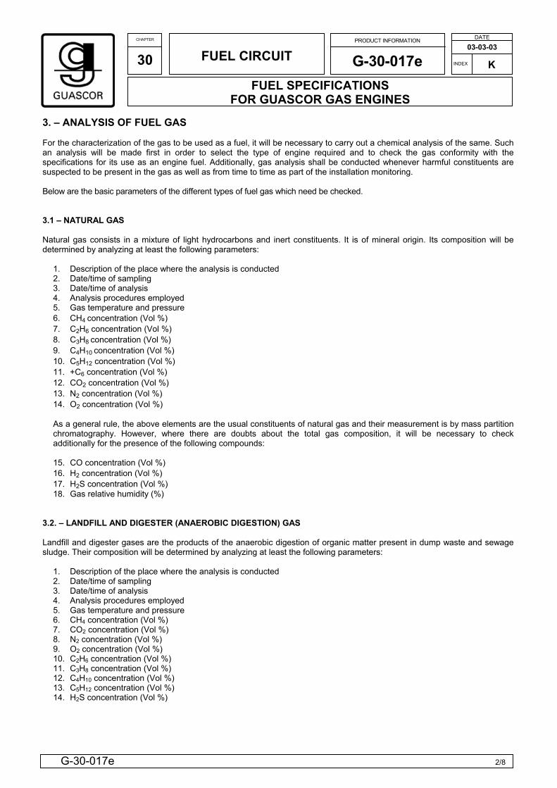
1. Description of the place where the analysis is conducted 2. Date/time of sampling 3. Date/time of analysis 4. Analysis procedures employed 5. Gas temperature and pressure 6. CH4 concentration (Vol %) 7. C2H6 concentration (Vol %) 8. C3H8 concentration (Vol %) 9. C4H10 concentration (Vol %) 10. C5H12 concentration (Vol %) 11. +C6 concentration (Vol %) 12. CO2 concentration (Vol %) 13. N2 concentration (Vol %) 14. O2 concentration (Vol %) As a general rule, the above elements are the usual constituents of natural gas and their measurement is by mass partition chromatography. However, where there are doubts about the total gas composition, it will be necessary to check additionally for the presence of the following compounds: 15. CO concentration (Vol %) 16. H2 concentration (Vol %) 17. H2S concentration (Vol %) 18. Gas relative humidity (%)
3.2. – LANDFILL AND DIGESTER (ANAEROBIC DIGESTION) GAS Landfill and digester gases are the products of the anaerobic digestion of organic matter present in dump waste and sewage sludge. Their composition will be determined by analyzing at least the following parameters:
1. Description of the place where the analysis is conducted 2. Date/time of sampling 3. Date/time of analysis 4. Analysis procedures employed 5. Gas temperature and pressure 6. CH4 concentration (Vol %) 7. CO2 concentration (Vol %) 8. N2 concentration (Vol %) 9. O2 concentration (Vol %) 10. C2H6 concentration (Vol %) 11. C3H8 concentration (Vol %) 12. C4H10 concentration (Vol %) 13. C5H12 concentration (Vol %) 14. H2S concentration (Vol %)
CHAPTER
30
FUEL CIRCUIT PRODUCT INFORMATION
G-30-017e FUEL SPECIFICATIONS
FOR GUASCOR GAS ENGINES
DATE
03-03-03 INDEX
3/8G-30-017e
K
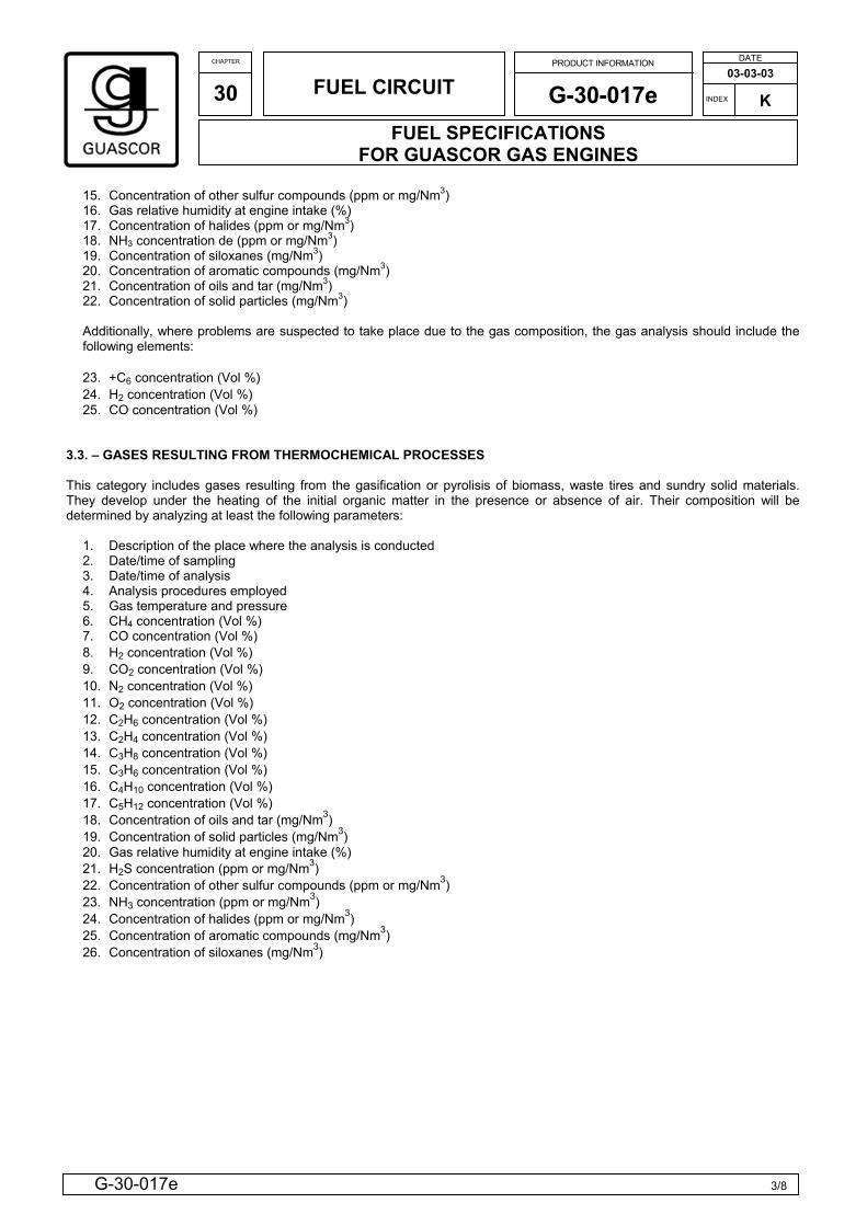
15. Concentration of other sulfur compounds (ppm or mg/Nm3) 16. Gas relative humidity at engine intake (%) 17. Concentration of halides (ppm or mg/Nm3) 18. NH3 concentration de (ppm or mg/Nm3) 19. Concentration of siloxanes (mg/Nm3) 20. Concentration of aromatic compounds (mg/Nm3) 21. Concentration of oils and tar (mg/Nm3) 22. Concentration of solid particles (mg/Nm3) Additionally, where problems are suspected to take place due to the gas composition, the gas analysis should include the following elements: 23. +C6 concentration (Vol %) 24. H2 concentration (Vol %) 25. CO concentration (Vol %)
3.3. – GASES RESULTING FROM THERMOCHEMICAL PROCESSES This category includes gases resulting from the gasification or pyrolisis of biomass, waste tires and sundry solid materials. They develop under the heating of the initial organic matter in the presence or absence of air. Their composition will be determined by analyzing at least the following parameters:
1. Description of the place where the analysis is conducted 2. Date/time of sampling 3. Date/time of analysis 4. Analysis procedures employed 5. Gas temperature and pressure 6. CH4 concentration (Vol %) 7. CO concentration (Vol %) 8. H2 concentration (Vol %) 9. CO2 concentration (Vol %) 10. N2 concentration (Vol %) 11. O2 concentration (Vol %) 12. C2H6 concentration (Vol %) 13. C2H4 concentration (Vol %) 14. C3H8 concentration (Vol %) 15. C3H6 concentration (Vol %) 16. C4H10 concentration (Vol %) 17. C5H12 concentration (Vol %) 18. Concentration of oils and tar (mg/Nm3) 19. Concentration of solid particles (mg/Nm3) 20. Gas relative humidity at engine intake (%) 21. H2S concentration (ppm or mg/Nm3) 22. Concentration of other sulfur compounds (ppm or mg/Nm3) 23. NH3 concentration (ppm or mg/Nm3) 24. Concentration of halides (ppm or mg/Nm3) 25. Concentration of aromatic compounds (mg/Nm3) 26. Concentration of siloxanes (mg/Nm3)
CHAPTER
30
FUEL CIRCUIT PRODUCT INFORMATION
G-30-017e FUEL SPECIFICATIONS
FOR GUASCOR GAS ENGINES
DATE
03-03-03 INDEX
4/8G-30-017e
K
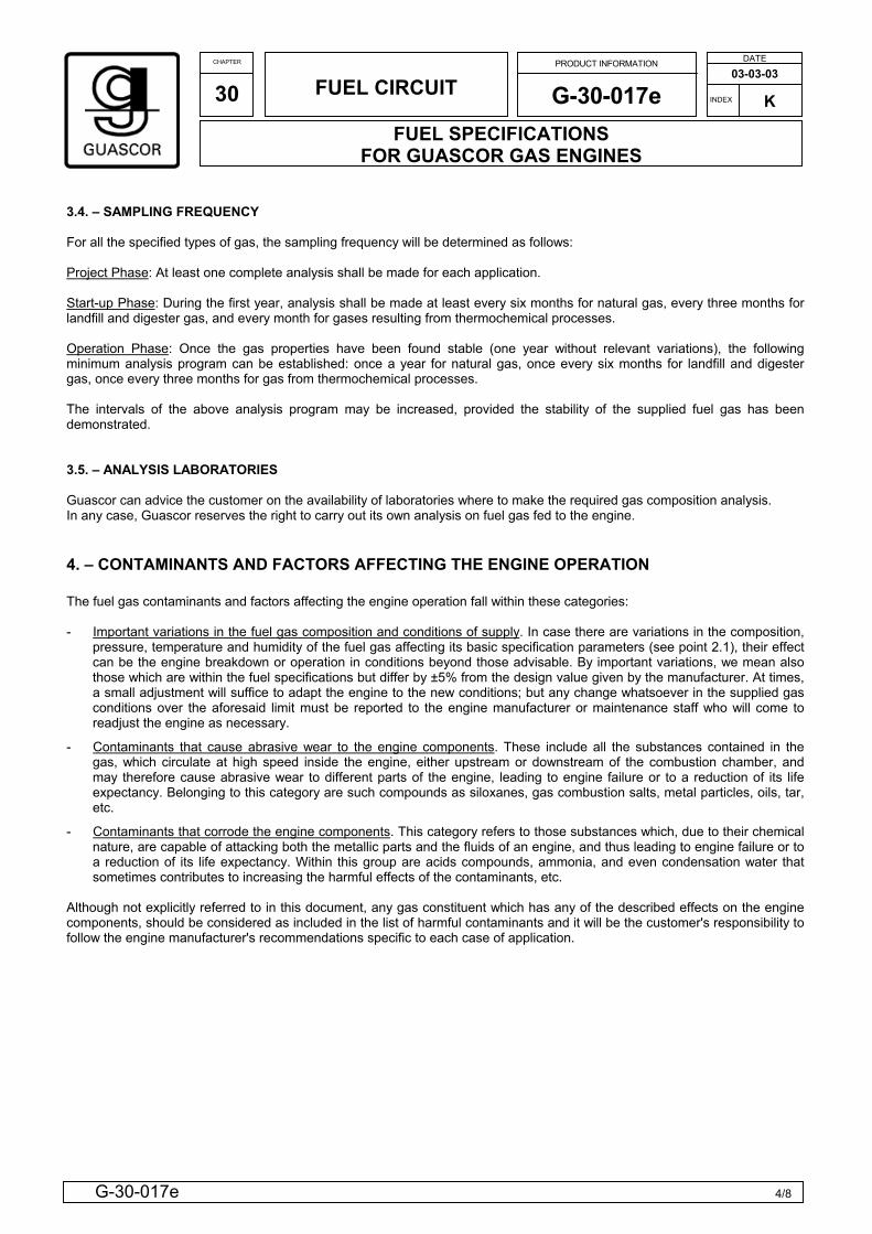
3.4. – SAMPLING FREQUENCY For all the specified types of gas, the sampling frequency will be determined as follows: Project Phase: At least one complete analysis shall be made for each application. Start-up Phase: During the first year, analysis shall be made at least every six months for natural gas, every three months for landfill and digester gas, and every month for gases resulting from thermochemical processes. Operation Phase: Once the gas properties have been found stable (one year without relevant variations), the following minimum analysis program can be established: once a year for natural gas, once every six months for landfill and digester gas, once every three months for gas from thermochemical processes. The intervals of the above analysis program may be increased, provided the stability of the supplied fuel gas has been demonstrated. 3.5. – ANALYSIS LABORATORIES Guascor can advice the customer on the availability of laboratories where to make the required gas composition analysis. In any case, Guascor reserves the right to carry out its own analysis on fuel gas fed to the engine. 4. – CONTAMINANTS AND FACTORS AFFECTING THE ENGINE OPERATION The fuel gas contaminants and factors affecting the engine operation fall within these categories: - Important variations in the fuel gas composition and conditions of supply. In case there are variations in the composition,
pressure, temperature and humidity of the fuel gas affecting its basic specification parameters (see point 2.1), their effect can be the engine breakdown or operation in conditions beyond those advisable. By important variations, we mean also those which are within the fuel specifications but differ by ±5% from the design value given by the manufacturer. At times, a small adjustment will suffice to adapt the engine to the new conditions; but any change whatsoever in the supplied gas conditions over the aforesaid limit must be reported to the engine manufacturer or maintenance staff who will come to readjust the engine as necessary.
- Contaminants that cause abrasive wear to the engine components. These include all the substances contained in the gas, which circulate at high speed inside the engine, either upstream or downstream of the combustion chamber, and may therefore cause abrasive wear to different parts of the engine, leading to engine failure or to a reduction of its life expectancy. Belonging to this category are such compounds as siloxanes, gas combustion salts, metal particles, oils, tar, etc.
- Contaminants that corrode the engine components. This category refers to those substances which, due to their chemical nature, are capable of attacking both the metallic parts and the fluids of an engine, and thus leading to engine failure or to a reduction of its life expectancy. Within this group are acids compounds, ammonia, and even condensation water that sometimes contributes to increasing the harmful effects of the contaminants, etc.
Although not explicitly referred to in this document, any gas constituent which has any of the described effects on the engine components, should be considered as included in the list of harmful contaminants and it will be the customer's responsibility to follow the engine manufacturer's recommendations specific to each case of application.
CHAPTER
30
FUEL CIRCUIT PRODUCT INFORMATION
G-30-017e FUEL SPECIFICATIONS
FOR GUASCOR GAS ENGINES
DATE
03-03-03 INDEX
5/8G-30-017e
K
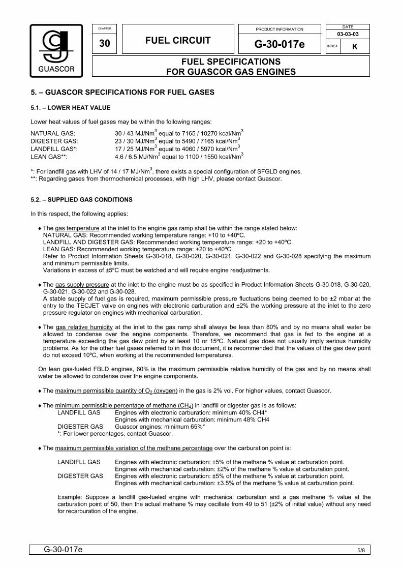
5. – GUASCOR SPECIFICATIONS FOR FUEL GASES 5.1. – LOWER HEAT VALUE
Lower heat values of fuel gases may be within the following ranges:
NATURAL GAS: 30 / 43 MJ/Nm3 equal to 7165 / 10270 kcal/Nm3 DIGESTER GAS: 23 / 30 MJ/Nm3 equal to 5490 / 7165 kcal/Nm3 LANDFILL GAS*: 17 / 25 MJ/Nm3 equal to 4060 / 5970 kcal/Nm3 LEAN GAS**: 4.6 / 6.5 MJ/Nm3 equal to 1100 / 1550 kcal/Nm3 *: For landfill gas with LHV of 14 / 17 MJ/Nm3, there exists a special configuration of SFGLD engines. **: Regarding gases from thermochemical processes, with high LHV, please contact Guascor. 5.2. – SUPPLIED GAS CONDITIONS
In this respect, the following applies:
♦The gas temperature at the inlet to the engine gas ramp shall be within the range stated below: NATURAL GAS: Recommended working temperature range: +10 to +40ºC. LANDFILL AND DIGESTER GAS: Recommended working temperature range: +20 to +40ºC. LEAN GAS: Recommended working temperature range: +20 to +40ºC. Refer to Product Information Sheets G-30-018, G-30-020, G-30-021, G-30-022 and G-30-028 specifying the maximum and minimum permissible limits. Variations in excess of ±5ºC must be watched and will require engine readjustments.
♦The gas supply pressure at the inlet to the engine must be as specified in Product Information Sheets G-30-018, G-30-020,
G-30-021, G-30-022 and G-30-028. A stable supply of fuel gas is required, maximum permissible pressure fluctuations being deemed to be ±2 mbar at the entry to the TECJET valve on engines with electronic carburation and ±2% the working pressure at the inlet to the zero pressure regulator on engines with mechanical carburation.
♦The gas relative humidity at the inlet to the gas ramp shall always be less than 80% and by no means shall water be
allowed to condense over the engine components. Therefore, we recommend that gas is fed to the engine at a temperature exceeding the gas dew point by at least 10 or 15ºC. Natural gas does not usually imply serious humidity problems. As for the other fuel gases referred to in this document, it is recommended that the values of the gas dew point do not exceed 10ºC, when working at the recommended temperatures.
On lean gas-fueled FBLD engines, 60% is the maximum permissible relative humidity of the gas and by no means shall water be allowed to condense over the engine components.
♦The maximum permissible quantity of O2 (oxygen) in the gas is 2% vol. For higher values, contact Guascor.
♦The minimum permissible percentage of methane (CH4) in landfill or digester gas is as follows:
LANDFILL GAS Engines with electronic carburation: minimum 40% CH4* Engines with mechanical carburation: minimum 48% CH4 DIGESTER GAS Guascor engines: minimum 65%* *: For lower percentages, contact Guascor.
♦The maximum permissible variation of the methane percentage over the carburation point is:
LANDIFLL GAS Engines with electronic carburation: ±5% of the methane % value at carburation point. Engines with mechanical carburation: ±2% of the methane % value at carburation point. DIGESTER GAS Engines with electronic carburation: ±5% of the methane % value at carburation point. Engines with mechanical carburation: ±3.5% of the methane % value at carburation point.
Example: Suppose a landfill gas-fueled engine with mechanical carburation and a gas methane % value at the carburation point of 50, then the actual methane % may oscillate from 49 to 51 (±2% of initial value) without any need for recarburation of the engine.
CHAPTER
30
FUEL CIRCUIT PRODUCT INFORMATION
G-30-017e FUEL SPECIFICATIONS
FOR GUASCOR GAS ENGINES
DATE
03-03-03 INDEX
6/8G-30-017e
K
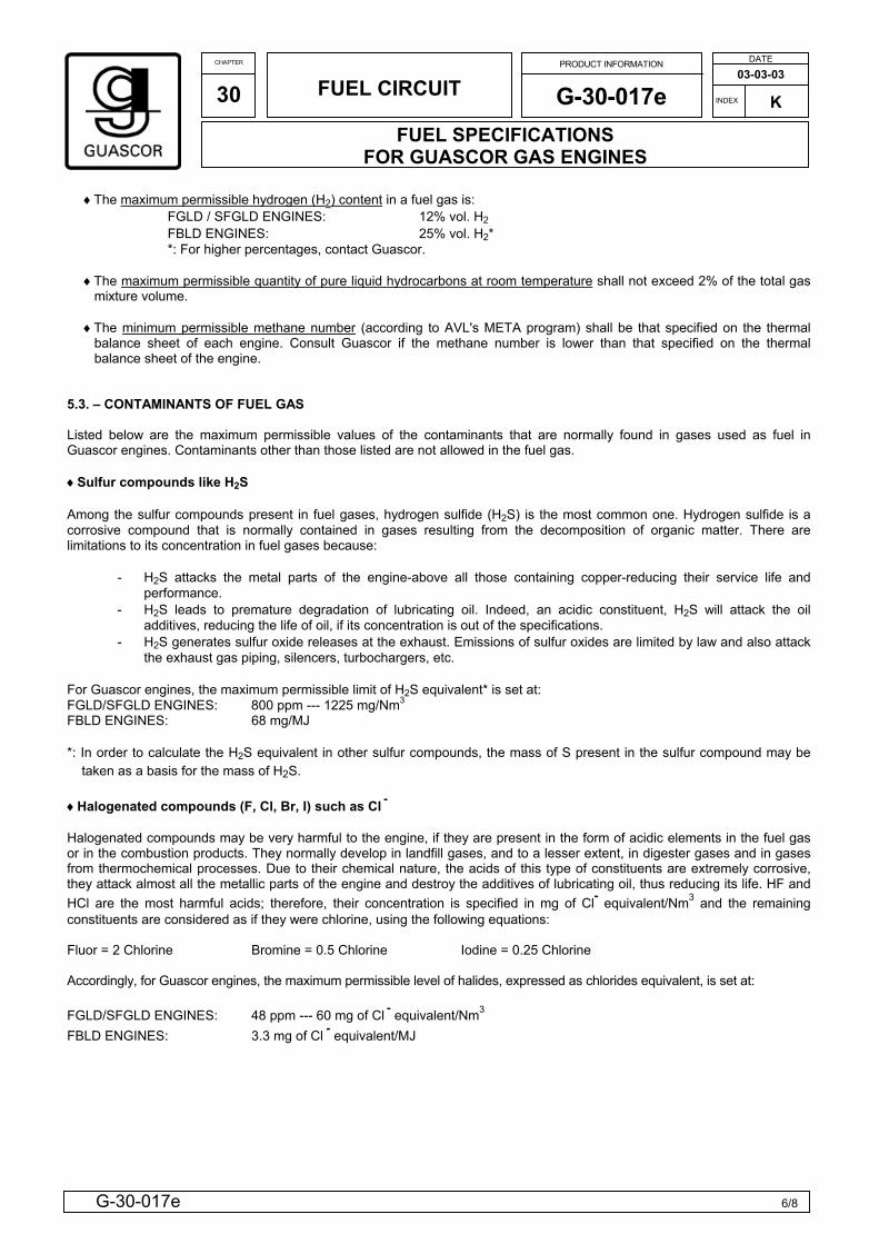
♦The maximum permissible hydrogen (H2) content in a fuel gas is:
FGLD / SFGLD ENGINES: 12% vol. H2 FBLD ENGINES: 25% vol. H2* *: For higher percentages, contact Guascor.
♦The maximum permissible quantity of pure liquid hydrocarbons at room temperature shall not exceed 2% of the total gas mixture volume.
♦The minimum permissible methane number (according to AVL's META program) shall be that specified on the thermal
balance sheet of each engine. Consult Guascor if the methane number is lower than that specified on the thermal balance sheet of the engine.
5.3. – CONTAMINANTS OF FUEL GAS Listed below are the maximum permissible values of the contaminants that are normally found in gases used as fuel in Guascor engines. Contaminants other than those listed are not allowed in the fuel gas. ♦Sulfur compounds like H2S Among the sulfur compounds present in fuel gases, hydrogen sulfide (H2S) is the most common one. Hydrogen sulfide is a corrosive compound that is normally contained in gases resulting from the decomposition of organic matter. There are limitations to its concentration in fuel gases because:
- H2S attacks the metal parts of the engine-above all those containing copper-reducing their service life and performance.
- H2S leads to premature degradation of lubricating oil. Indeed, an acidic constituent, H2S will attack the oil additives, reducing the life of oil, if its concentration is out of the specifications.
- H2S generates sulfur oxide releases at the exhaust. Emissions of sulfur oxides are limited by law and also attack the exhaust gas piping, silencers, turbochargers, etc.
For Guascor engines, the maximum permissible limit of H2S equivalent* is set at: FGLD/SFGLD ENGINES: 800 ppm --- 1225 mg/Nm3 FBLD ENGINES: 68 mg/MJ *: In order to calculate the H2S equivalent in other sulfur compounds, the mass of S present in the sulfur compound may be
taken as a basis for the mass of H2S. ♦Halogenated compounds (F, Cl, Br, I) such as Cl - Halogenated compounds may be very harmful to the engine, if they are present in the form of acidic elements in the fuel gas or in the combustion products. They normally develop in landfill gases, and to a lesser extent, in digester gases and in gases from thermochemical processes. Due to their chemical nature, the acids of this type of constituents are extremely corrosive, they attack almost all the metallic parts of the engine and destroy the additives of lubricating oil, thus reducing its life. HF and HCl are the most harmful acids; therefore, their concentration is specified in mg of Cl- equivalent/Nm3 and the remaining constituents are considered as if they were chlorine, using the following equations: Fluor = 2 Chlorine Bromine = 0.5 Chlorine Iodine = 0.25 Chlorine Accordingly, for Guascor engines, the maximum permissible level of halides, expressed as chlorides equivalent, is set at: FGLD/SFGLD ENGINES: 48 ppm --- 60 mg of Cl - equivalent/Nm3 FBLD ENGINES: 3.3 mg of Cl - equivalent/MJ
CHAPTER
30
FUEL CIRCUIT PRODUCT INFORMATION
G-30-017e FUEL SPECIFICATIONS
FOR GUASCOR GAS ENGINES
DATE
03-03-03 INDEX
7/8G-30-017e
K
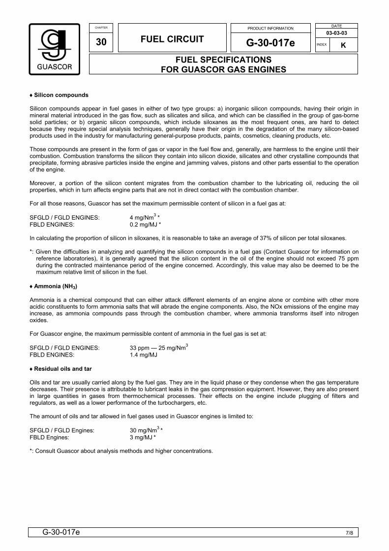
♦Silicon compounds Silicon compounds appear in fuel gases in either of two type groups: a) inorganic silicon compounds, having their origin in mineral material introduced in the gas flow, such as silicates and silica, and which can be classified in the group of gas-borne solid particles; or b) organic silicon compounds, which include siloxanes as the most frequent ones, are hard to detect because they require special analysis techniques, generally have their origin in the degradation of the many silicon-based products used in the industry for manufacturing general-purpose products, paints, cosmetics, cleaning products, etc. Those compounds are present in the form of gas or vapor in the fuel flow and, generally, are harmless to the engine until their combustion. Combustion transforms the silicon they contain into silicon dioxide, silicates and other crystalline compounds that precipitate, forming abrasive particles inside the engine and jamming valves, pistons and other parts essential to the operation of the engine. Moreover, a portion of the silicon content migrates from the combustion chamber to the lubricating oil, reducing the oil properties, which in turn affects engine parts that are not in direct contact with the combustion chamber. For all those reasons, Guascor has set the maximum permissible content of silicon in a fuel gas at: SFGLD / FGLD ENGINES: 4 mg/Nm3 * FBLD ENGINES: 0.2 mg/MJ * In calculating the proportion of silicon in siloxanes, it is reasonable to take an average of 37% of silicon per total siloxanes. *: Given the difficulties in analyzing and quantifying the silicon compounds in a fuel gas (Contact Guascor for information on
reference laboratories), it is generally agreed that the silicon content in the oil of the engine should not exceed 75 ppm during the contracted maintenance period of the engine concerned. Accordingly, this value may also be deemed to be the maximum relative limit of silicon in the fuel.
♦Ammonia (NH3) Ammonia is a chemical compound that can either attack different elements of an engine alone or combine with other more acidic constituents to form ammonia salts that will abrade the engine components. Also, the NOx emissions of the engine may increase, as ammonia compounds pass through the combustion chamber, where ammonia transforms itself into nitrogen oxides. For Guascor engine, the maximum permissible content of ammonia in the fuel gas is set at: SFGLD / FGLD ENGINES: 33 ppm --- 25 mg/Nm3 FBLD ENGINES: 1.4 mg/MJ ♦Residual oils and tar Oils and tar are usually carried along by the fuel gas. They are in the liquid phase or they condense when the gas temperature decreases. Their presence is attributable to lubricant leaks in the gas compression equipment. However, they are also present in large quantities in gases from thermochemical processes. Their effects on the engine include plugging of filters and regulators, as well as a lower performance of the turbochargers, etc. The amount of oils and tar allowed in fuel gases used in Guascor engines is limited to: SFGLD / FGLD Engines: 30 mg/Nm3 * FBLD Engines: 3 mg/MJ * *: Consult Guascor about analysis methods and higher concentrations.
CHAPTER
30
FUEL CIRCUIT PRODUCT INFORMATION
G-30-017e FUEL SPECIFICATIONS
FOR GUASCOR GAS ENGINES
DATE
03-03-03 INDEX
8/8G-30-017e
K
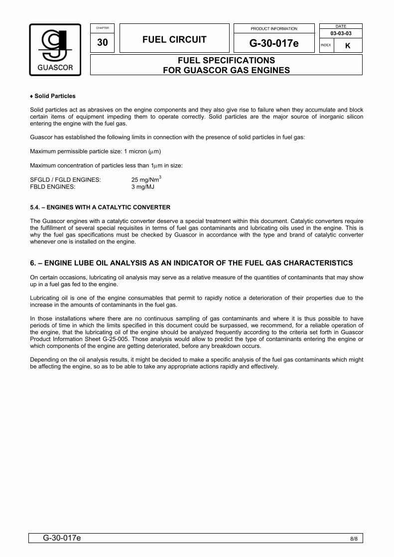
♦Solid Particles Solid particles act as abrasives on the engine components and they also give rise to failure when they accumulate and block certain items of equipment impeding them to operate correctly. Solid particles are the major source of inorganic silicon entering the engine with the fuel gas. Guascor has established the following limits in connection with the presence of solid particles in fuel gas: Maximum permissible particle size: 1 micron (µm) Maximum concentration of particles less than 1µm in size: SFGLD / FGLD ENGINES: 25 mg/Nm3
FBLD ENGINES: 3 mg/MJ 5.4. – ENGINES WITH A CATALYTIC CONVERTER The Guascor engines with a catalytic converter deserve a special treatment within this document. Catalytic converters require the fulfillment of several special requisites in terms of fuel gas contaminants and lubricating oils used in the engine. This is why the fuel gas specifications must be checked by Guascor in accordance with the type and brand of catalytic converter whenever one is installed on the engine. 6. – ENGINE LUBE OIL ANALYSIS AS AN INDICATOR OF THE FUEL GAS CHARACTERISTICS On certain occasions, lubricating oil analysis may serve as a relative measure of the quantities of contaminants that may show up in a fuel gas fed to the engine. Lubricating oil is one of the engine consumables that permit to rapidly notice a deterioration of their properties due to the increase in the amounts of contaminants in the fuel gas. In those installations where there are no continuous sampling of gas contaminants and where it is thus possible to have periods of time in which the limits specified in this document could be surpassed, we recommend, for a reliable operation of the engine, that the lubricating oil of the engine should be analyzed frequently according to the criteria set forth in Guascor Product Information Sheet G-25-005. Those analysis would allow to predict the type of contaminants entering the engine or which components of the engine are getting deteriorated, before any breakdown occurs. Depending on the oil analysis results, it might be decided to make a specific analysis of the fuel gas contaminants which might be affecting the engine, so as to be able to take any appropriate actions rapidly and effectively.
———————————————————————
19
FGLD-SFGLD /2 ENGINES / 55
NATURAL GAS 1500 RPM
IRAN
ANNEX 3
GUASCOR GAS ENGINES THERMAL BALANCES

GROUP INDEX
DEP. 2
ENGINE: FGLD 180JACKET WATER TEMPERATURE(ºC): 90INTERCOOLER WATER TEMP(ºC): 55
APLICATION: CONTINUOUS COMPRESSION RATIO: 11:1COOLING SYSTEM: TWO CIRCUITS REGULATION:AIR COOLER: 1 STEP IGNITION TIMING: 18ºEXHAUST MANFOLD TYPE: WATER COOLED MAX. BACK PRESSURE: 450 mmH2OEMISSIONS: N/A
AMBIENT CONDITIONS ISO 3046/1:Atmospheric pressure (kPa)= 100
Ambient temperature (ºC)= 25Relative humidity (%)= 30
LOAD % 100% 60% 40%MECHANICAL POWER (3, 4, 5) kWb 275 165 110BMEP bar 12,2 7,3 4,9FUEL CONSUMPTION (1) kW 686 443 324THERMAL EFFICIENCY % 40,1 37,3 34,0
HEAT IN MAIN WATER CIRCUIT (1) kW 175 120 93
HEAT IN SECONDARY WATER CIRCUIT (1) kW 57 37 28HEAT IN CHARGE COOLER (1) kW 25 7 1HEAT IN OIL COOLER (1) kW 32 30 27
HEAT IN EXHAUST GASES (25 ºC) (1) kW 160 106 79HEAT IN EXHAUST GASES (120ºC) (1) kW 119 80 60EXHAUST GAS TEMPERATURE (1) ºC 400 414 422HEAT TO RADIATION (1) kW 19 15 14
O2 TO EXHAUST(DRY)(ONLY A REFERENCE) % 8,95 8,52 8,47
INTAKE AIR FLOW (1) kg/h 1280 820 600EXHAUST GAS FLOW (WET) (1) kg/h 1330 850 620
NOTES:1. 100% LOAD TOLERANCES:
FUEL CONSUMPTION ±5%, COOLING CIRCUIT AND EXHAUST GASES ± 15%, RADIATION ±25 EXHAUST TEMPERATURE ±20ºC, MASS FLOWS ± 10%.2. THE ENGINE PERFORMANCE DATA, TIMING ADVANCE AND CARBURATION SETTINGS ARE VALID FOR A GAS THAT FULFILLS THE REQUIREMENTS DEFINED IN IC-G-D-30-001 AND IC-G-D-30-0023. NET POWER, MECHANICAL PUMPS NOT INCLUDED.4.POWERS ARE VALID FOR AMBIENT TEMP.< 25ºC AND AN ALTITUDE OF < 500m.5. OVERLOAD NOT ALLOWED6. THE SPECIFICATIONS AND MATERIALS ARE SUBJCT TO CHANGE WITHOUT NOTIFICATION7. A ENGINE WITH INLET OR OUTPUT RESTRICTION OVER PUBLISHED LIMITS, OR WITH INADEQUATE MAINTENANCE OR INSTALLATION CAN MODIFY POWER RATING DATA.8. EMISSIONS ARE CORRECTED TO 5% OF O2
Elab: Version: 1.0/270904 1/1
10401080
46
POWER RATING (4)
CARBURATION SETTINGS (2)8,8
9,8562
15
80%
GAS
99
DATE
31
132
PARTIAL LOADSNOMINAL
220
MASS FLOWS
PRODUCT INORMATION
IC-G-B-IC-012
Cod.: CCod.:5C
408
IC
39,2
148
Manual
idta
08-02-05POWER RATING
Natural GasFUEL TYPE:
SPEED: 1500
G-00-239
16
GROUP INDEX
DEP. 2
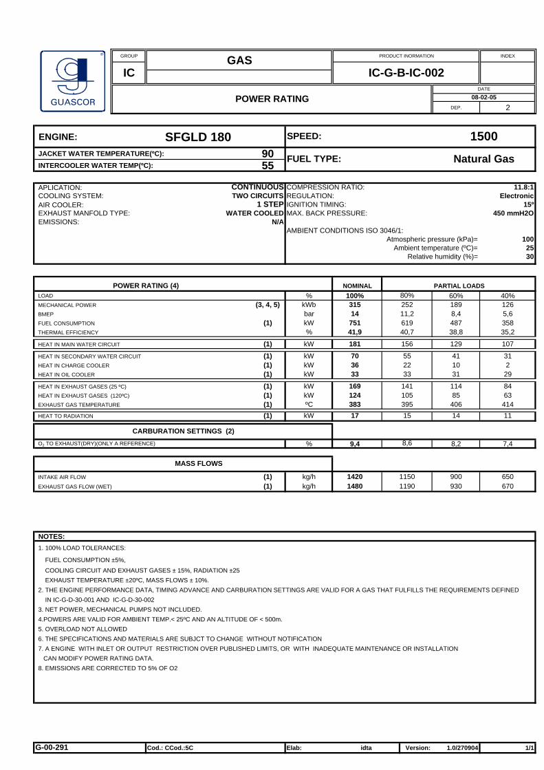
ENGINE: SFGLD 180JACKET WATER TEMPERATURE(ºC): 90INTERCOOLER WATER TEMP(ºC): 55
APLICATION: CONTINUOUS COMPRESSION RATIO: 11.8:1COOLING SYSTEM: TWO CIRCUITS REGULATION:AIR COOLER: 1 STEP IGNITION TIMING: 15ºEXHAUST MANFOLD TYPE: WATER COOLED MAX. BACK PRESSURE: 450 mmH2OEMISSIONS: N/A
AMBIENT CONDITIONS ISO 3046/1:Atmospheric pressure (kPa)= 100
Ambient temperature (ºC)= 25Relative humidity (%)= 30
LOAD % 100% 60% 40%MECHANICAL POWER (3, 4, 5) kWb 315 189 126BMEP bar 14 8,4 5,6FUEL CONSUMPTION (1) kW 751 487 358THERMAL EFFICIENCY % 41,9 38,8 35,2
HEAT IN MAIN WATER CIRCUIT (1) kW 181 129 107
HEAT IN SECONDARY WATER CIRCUIT (1) kW 70 41 31HEAT IN CHARGE COOLER (1) kW 36 10 2HEAT IN OIL COOLER (1) kW 33 31 29
HEAT IN EXHAUST GASES (25 ºC) (1) kW 169 114 84HEAT IN EXHAUST GASES (120ºC) (1) kW 124 85 63EXHAUST GAS TEMPERATURE (1) ºC 383 406 414HEAT TO RADIATION (1) kW 17 14 11
O2 TO EXHAUST(DRY)(ONLY A REFERENCE) % 9,4 8,2 7,4
INTAKE AIR FLOW (1) kg/h 1420 900 650EXHAUST GAS FLOW (WET) (1) kg/h 1480 930 670
NOTES:1. 100% LOAD TOLERANCES:
FUEL CONSUMPTION ±5%, COOLING CIRCUIT AND EXHAUST GASES ± 15%, RADIATION ±25 EXHAUST TEMPERATURE ±20ºC, MASS FLOWS ± 10%.2. THE ENGINE PERFORMANCE DATA, TIMING ADVANCE AND CARBURATION SETTINGS ARE VALID FOR A GAS THAT FULFILLS THE REQUIREMENTS DEFINED IN IC-G-D-30-001 AND IC-G-D-30-0023. NET POWER, MECHANICAL PUMPS NOT INCLUDED.4.POWERS ARE VALID FOR AMBIENT TEMP.< 25ºC AND AN ALTITUDE OF < 500m.5. OVERLOAD NOT ALLOWED6. THE SPECIFICATIONS AND MATERIALS ARE SUBJCT TO CHANGE WITHOUT NOTIFICATION7. A ENGINE WITH INLET OR OUTPUT RESTRICTION OVER PUBLISHED LIMITS, OR WITH INADEQUATE MAINTENANCE OR INSTALLATION CAN MODIFY POWER RATING DATA.8. EMISSIONS ARE CORRECTED TO 5% OF O2
Elab: Version: 1.0/270904 1/1
11501190
55
POWER RATING (4)
CARBURATION SETTINGS (2)8,6
11,2619
22
80%
GAS
105
DATE
33
141
PARTIAL LOADSNOMINAL
252
MASS FLOWS
PRODUCT INORMATION
IC-G-B-IC-002
Cod.: CCod.:5C
395
IC
40,7
156
Electronic
idta
08-02-05POWER RATING
Natural GasFUEL TYPE:
SPEED: 1500
G-00-291
15

GROUP INDEX
DEP. 2
ENGINE: FGLD 240JACKET WATER TEMPERATURE(ºC): 90INTERCOOLER WATER TEMP(ºC): 55
APLICATION: CONTINUOUS COMPRESSION RATIO: 11:1COOLING SYSTEM: TWO CIRCUITS REGULATION:AIR COOLER: 1 STEP IGNITION TIMING: 18ºEXHAUST MANFOLD TYPE: WATER COOLED MAX. BACK PRESSURE: 450 mmH2OEMISSIONS: N/A
AMBIENT CONDITIONS ISO 3046/1:Atmospheric pressure (kPa)= 100
Ambient temperature (ºC)= 25Relative humidity (%)= 30
LOAD % 100% 60% 40%MECHANICAL POWER (3, 4, 5) kWb 360 216 144BMEP bar 12 7,2 4,8FUEL CONSUMPTION (1) kW 924 595 433THERMAL EFFICIENCY % 39,0 36,3 33,2
HEAT IN MAIN WATER CIRCUIT (1) kW 249 168 131
HEAT IN SECONDARY WATER CIRCUIT (1) kW 82 51 34HEAT IN CHARGE COOLER (1) kW 39 13 ***HEAT IN OIL COOLER (1) kW 43 38 34
HEAT IN EXHAUST GASES (25 ºC) (1) kW 209 142 107HEAT IN EXHAUST GASES (120ºC) (1) kW 155 107 82EXHAUST GAS TEMPERATURE (1) ºC 392 413 425HEAT TO RADIATION (1) kW 24 19 17
O2 TO EXHAUST(DRY)(ONLY A REFERENCE) % 8,96 8,75 8,47
INTAKE AIR FLOW (1) kg/h 1720 1100 800EXHAUST GAS FLOW (WET) (1) kg/h 1780 1140 840
NOTES:1. 100% LOAD TOLERANCES:
FUEL CONSUMPTION ±5%, COOLING CIRCUIT AND EXHAUST GASES ± 15%, RADIATION ±25 EXHAUST TEMPERATURE ±20ºC, MASS FLOWS ± 10%.2. THE ENGINE PERFORMANCE DATA, TIMING ADVANCE AND CARBURATION SETTINGS ARE VALID FOR A GAS THAT FULFILLS THE REQUIREMENTS DEFINED IN IC-G-D-30-001 AND IC-G-D-30-0023. NET POWER, MECHANICAL PUMPS NOT INCLUDED.4.POWERS ARE VALID FOR AMBIENT TEMP.< 25ºC AND AN ALTITUDE OF < 500m.5. OVERLOAD NOT ALLOWED6. THE SPECIFICATIONS AND MATERIALS ARE SUBJCT TO CHANGE WITHOUT NOTIFICATION7. A ENGINE WITH INLET OR OUTPUT RESTRICTION OVER PUBLISHED LIMITS, OR WITH INADEQUATE MAINTENANCE OR INSTALLATION CAN MODIFY POWER RATING DATA.8. EMISSIONS ARE CORRECTED TO 5% OF O2
Elab: Version: 1.0/270904 1/1
13901440
68
POWER RATING (4)
CARBURATION SETTINGS (2)8,91
9,6757
27
80%
GAS
131
DATE
41
174
PARTIAL LOADSNOMINAL
288
MASS FLOWS
PRODUCT INORMATION
IC-G-B-IC-012
Cod.: CCod.:5C
403
IC
38,0
206
Manual
idta
08-02-05POWER RATING
Natural GasFUEL TYPE:
SPEED: 1500
G-00-231
21

GROUP INDEX
DEP. 2
ENGINE: SFGLD 240JACKET WATER TEMPERATURE(ºC): 90INTERCOOLER WATER TEMP(ºC): 55
APLICATION: CONTINUOUS COMPRESSION RATIO: 11.8:1COOLING SYSTEM: TWO CIRCUITS REGULATION:AIR COOLER: 1 STEP IGNITION TIMING: 15ºEXHAUST MANFOLD TYPE: WATER COOLED MAX. BACK PRESSURE: 450 mmH2OEMISSIONS: N/A
AMBIENT CONDITIONS ISO 3046/1:Atmospheric pressure (kPa)= 100
Ambient temperature (ºC)= 25Relative humidity (%)= 30
LOAD % 100% 60% 40%MECHANICAL POWER (3, 4, 5) kWb 419 252 168BMEP bar 14 8,4 5,6FUEL CONSUMPTION (1) kW 1023 650 474THERMAL EFFICIENCY % 41,0 38,8 35,4
HEAT IN MAIN WATER CIRCUIT (1) kW 253 174 138
HEAT IN SECONDARY WATER CIRCUIT (1) kW 104 56 42HEAT IN CHARGE COOLER (1) kW 58 16 4HEAT IN OIL COOLER (1) kW 47 40 38
HEAT IN EXHAUST GASES (25 ºC) (1) kW 225 150 112HEAT IN EXHAUST GASES (120ºC) (1) kW 165 113 84EXHAUST GAS TEMPERATURE (1) ºC 382 405 416HEAT TO RADIATION (1) kW 22 17 15
O2 TO EXHAUST(DRY)(ONLY A REFERENCE) % 9,16 8,4 7,99
INTAKE AIR FLOW (1) kg/h 1900 1190 860EXHAUST GAS FLOW (WET) (1) kg/h 1970 1240 890
NOTES:1. 100% LOAD TOLERANCES:
FUEL CONSUMPTION ±5%, COOLING CIRCUIT AND EXHAUST GASES ± 15%, RADIATION ±25 EXHAUST TEMPERATURE ±20ºC, MASS FLOWS ± 10%.2. THE ENGINE PERFORMANCE DATA, TIMING ADVANCE AND CARBURATION SETTINGS ARE VALID FOR A GAS THAT FULFILLS THE REQUIREMENTS DEFINED IN IC-G-D-30-001 AND IC-G-D-30-0023. NET POWER, MECHANICAL PUMPS NOT INCLUDED.4.POWERS ARE VALID FOR AMBIENT TEMP.< 25ºC AND AN ALTITUDE OF < 500m.5. OVERLOAD NOT ALLOWED6. THE SPECIFICATIONS AND MATERIALS ARE SUBJCT TO CHANGE WITHOUT NOTIFICATION7. A ENGINE WITH INLET OR OUTPUT RESTRICTION OVER PUBLISHED LIMITS, OR WITH INADEQUATE MAINTENANCE OR INSTALLATION CAN MODIFY POWER RATING DATA.8. EMISSIONS ARE CORRECTED TO 5% OF O2
Elab: Version: 1.0/270904 1/1
15401600
81
POWER RATING (4)
CARBURATION SETTINGS (2)8,9
11,2840
36
80%
GAS
140
DATE
45
188
PARTIAL LOADSNOMINAL
336
MASS FLOWS
PRODUCT INORMATION
IC-G-B-IC-002
Cod.: CCod.:5C
393
IC
40,0
216
Electronic
idta
08-02-05POWER RATING
Natural GasFUEL TYPE:
SPEED: 1500
G-00-287
19
GROUP INDEX
DEP. 2
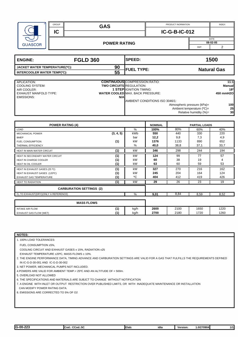
ENGINE: FGLD 360JACKET WATER TEMPERATURE(ºC): 90INTERCOOLER WATER TEMP(ºC): 55
APLICATION: CONTINUOUS COMPRESSION RATIO: 11:1COOLING SYSTEM: TWO CIRCUITS REGULATION:AIR COOLER: 1 STEP IGNITION TIMING: 18ºEXHAUST MANFOLD TYPE: WATER COOLED MAX. BACK PRESSURE: 450 mmH2OEMISSIONS: N/A
AMBIENT CONDITIONS ISO 3046/1:Atmospheric pressure (kPa)= 100
Ambient temperature (ºC)= 25Relative humidity (%)= 30
LOAD % 100% 60% 40%MECHANICAL POWER (3, 4, 5) kWb 550 330 220BMEP bar 12,2 7,3 4,9FUEL CONSUMPTION (1) kW 1376 890 652THERMAL EFFICIENCY % 40,0 37,1 33,7
HEAT IN MAIN WATER CIRCUIT (1) kW 346 244 194
HEAT IN SECONDARY WATER CIRCUIT (1) kW 124 77 57HEAT IN CHARGE COOLER (1) kW 60 19 4HEAT IN OIL COOLER (1) kW 63 59 53
HEAT IN EXHAUST GASES (25 ºC) (1) kW 327 216 162HEAT IN EXHAUST GASES (120ºC) (1) kW 245 164 124EXHAUST GAS TEMPERATURE (1) ºC 404 419 426HEAT TO RADIATION (1) kW 29 23 19
O2 TO EXHAUST(DRY)(ONLY A REFERENCE) % 9,01 8,59 8,52
INTAKE AIR FLOW (1) kg/h 2600 1650 1220EXHAUST GAS FLOW (WET) (1) kg/h 2700 1720 1260
NOTES:1. 100% LOAD TOLERANCES:
FUEL CONSUMPTION ±5%, COOLING CIRCUIT AND EXHAUST GASES ± 15%, RADIATION ±25 EXHAUST TEMPERATURE ±20ºC, MASS FLOWS ± 10%.2. THE ENGINE PERFORMANCE DATA, TIMING ADVANCE AND CARBURATION SETTINGS ARE VALID FOR A GAS THAT FULFILLS THE REQUIREMENTS DEFINED IN IC-G-D-30-001 AND IC-G-D-30-0023. NET POWER, MECHANICAL PUMPS NOT INCLUDED.4.POWERS ARE VALID FOR AMBIENT TEMP.< 25ºC AND AN ALTITUDE OF < 500m.5. OVERLOAD NOT ALLOWED6. THE SPECIFICATIONS AND MATERIALS ARE SUBJCT TO CHANGE WITHOUT NOTIFICATION7. A ENGINE WITH INLET OR OUTPUT RESTRICTION OVER PUBLISHED LIMITS, OR WITH INADEQUATE MAINTENANCE OR INSTALLATION CAN MODIFY POWER RATING DATA.8. EMISSIONS ARE CORRECTED TO 5% OF O2
Elab: Version: 1.0/270904 1/1
21002180
99
POWER RATING (4)
CARBURATION SETTINGS (2)8,84
9,81133
38
80%
GAS
204
DATE
60
270
PARTIAL LOADSNOMINAL
440
MASS FLOWS
PRODUCT INORMATION
IC-G-B-IC-012
Cod.: CCod.:5C
412
IC
38,8
298
Manual
idta
08-02-05POWER RATING
Natural GasFUEL TYPE:
SPEED: 1500
G-00-223
26

GROUP INDEX
DEP. 2
ENGINE: SFGLD 360JACKET WATER TEMPERATURE(ºC): 90INTERCOOLER WATER TEMP(ºC): 55
APLICATION: CONTINUOUS COMPRESSION RATIO: 11.8:1COOLING SYSTEM: TWO CIRCUITS REGULATION:AIR COOLER: 1 STEP IGNITION TIMING: 15ºEXHAUST MANFOLD TYPE: WATER COOLED MAX. BACK PRESSURE: 450 mmH2OEMISSIONS: N/A
AMBIENT CONDITIONS ISO 3046/1:Atmospheric pressure (kPa)= 100
Ambient temperature (ºC)= 25Relative humidity (%)= 30
LOAD % 100% 60% 40%MECHANICAL POWER (3, 4, 5) kWb 630 378 252BMEP bar 14 8,4 5,6FUEL CONSUMPTION (1) kW 1524 981 710THERMAL EFFICIENCY % 41,3 38,5 35,5
HEAT IN MAIN WATER CIRCUIT (1) kW 390 274 208
HEAT IN SECONDARY WATER CIRCUIT (1) kW 135 78 61HEAT IN CHARGE COOLER (1) kW 66 18 4HEAT IN OIL COOLER (1) kW 69 60 58
HEAT IN EXHAUST GASES (25 ºC) (1) kW 340 228 167HEAT IN EXHAUST GASES (120ºC) (1) kW 248 171 126EXHAUST GAS TEMPERATURE (1) ºC 378 404 414HEAT TO RADIATION (1) kW 29 23 21
O2 TO EXHAUST(DRY)(ONLY A REFERENCE) % 9,0 7,97 7,57
INTAKE AIR FLOW (1) kg/h 2900 1810 1290EXHAUST GAS FLOW (WET) (1) kg/h 3010 1880 1340
NOTES:1. 100% LOAD TOLERANCES:
FUEL CONSUMPTION ±5%, COOLING CIRCUIT AND EXHAUST GASES ± 15%, RADIATION ±25 EXHAUST TEMPERATURE ±20ºC, MASS FLOWS ± 10%.2. THE ENGINE PERFORMANCE DATA, TIMING ADVANCE AND CARBURATION SETTINGS ARE VALID FOR A GAS THAT FULFILLS THE REQUIREMENTS DEFINED IN IC-G-D-30-001 AND IC-G-D-30-0023. NET POWER, MECHANICAL PUMPS NOT INCLUDED.4.POWERS ARE VALID FOR AMBIENT TEMP.< 25ºC AND AN ALTITUDE OF < 500m.5. OVERLOAD NOT ALLOWED6. THE SPECIFICATIONS AND MATERIALS ARE SUBJCT TO CHANGE WITHOUT NOTIFICATION7. A ENGINE WITH INLET OR OUTPUT RESTRICTION OVER PUBLISHED LIMITS, OR WITH INADEQUATE MAINTENANCE OR INSTALLATION CAN MODIFY POWER RATING DATA.8. EMISSIONS ARE CORRECTED TO 5% OF O2
Elab: Version: 1.0/270904 1/1
23002390
108
POWER RATING (4)
CARBURATION SETTINGS (2)8,35
11,21248
43
80%
GAS
209
DATE
65
281
PARTIAL LOADSNOMINAL
504
MASS FLOWS
PRODUCT INORMATION
IC-G-B-IC-002
Cod.: CCod.:5C
393
IC
40,4
328
Electronic
idta
08-02-05POWER RATING
Natural GasFUEL TYPE:
SPEED: 1500
G-00-283
26
GROUP INDEX
DEP. 2
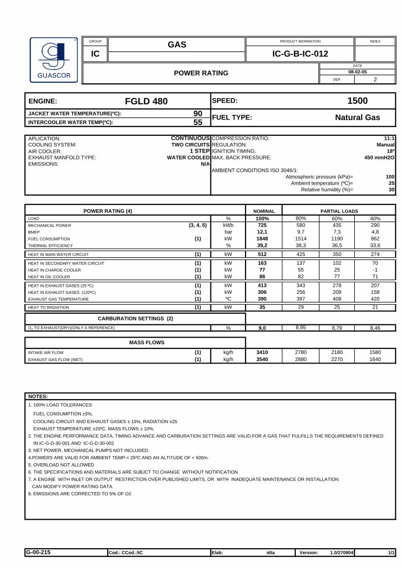
ENGINE: FGLD 480JACKET WATER TEMPERATURE(ºC): 90INTERCOOLER WATER TEMP(ºC): 55
APLICATION: CONTINUOUS COMPRESSION RATIO: 11:1COOLING SYSTEM: TWO CIRCUITS REGULATION:AIR COOLER: 1 STEP IGNITION TIMING: 18ºEXHAUST MANFOLD TYPE: WATER COOLED MAX. BACK PRESSURE: 450 mmH2OEMISSIONS: N/A
AMBIENT CONDITIONS ISO 3046/1:Atmospheric pressure (kPa)= 100
Ambient temperature (ºC)= 25Relative humidity (%)= 30
LOAD % 100% 60% 40%MECHANICAL POWER (3, 4, 5) kWb 725 435 290BMEP bar 12,1 7,3 4,8FUEL CONSUMPTION (1) kW 1848 1190 862THERMAL EFFICIENCY % 39,2 36,5 33,6
HEAT IN MAIN WATER CIRCUIT (1) kW 512 350 274
HEAT IN SECONDARY WATER CIRCUIT (1) kW 163 102 70HEAT IN CHARGE COOLER (1) kW 77 25 -1HEAT IN OIL COOLER (1) kW 86 77 71
HEAT IN EXHAUST GASES (25 ºC) (1) kW 413 278 207HEAT IN EXHAUST GASES (120ºC) (1) kW 306 209 158EXHAUST GAS TEMPERATURE (1) ºC 390 408 420HEAT TO RADIATION (1) kW 35 25 21
O2 TO EXHAUST(DRY)(ONLY A REFERENCE) % 9,0 8,79 8,46
INTAKE AIR FLOW (1) kg/h 3410 2180 1580EXHAUST GAS FLOW (WET) (1) kg/h 3540 2270 1640
NOTES:1. 100% LOAD TOLERANCES:
FUEL CONSUMPTION ±5%, COOLING CIRCUIT AND EXHAUST GASES ± 15%, RADIATION ±25 EXHAUST TEMPERATURE ±20ºC, MASS FLOWS ± 10%.2. THE ENGINE PERFORMANCE DATA, TIMING ADVANCE AND CARBURATION SETTINGS ARE VALID FOR A GAS THAT FULFILLS THE REQUIREMENTS DEFINED IN IC-G-D-30-001 AND IC-G-D-30-0023. NET POWER, MECHANICAL PUMPS NOT INCLUDED.4.POWERS ARE VALID FOR AMBIENT TEMP.< 25ºC AND AN ALTITUDE OF < 500m.5. OVERLOAD NOT ALLOWED6. THE SPECIFICATIONS AND MATERIALS ARE SUBJCT TO CHANGE WITHOUT NOTIFICATION7. A ENGINE WITH INLET OR OUTPUT RESTRICTION OVER PUBLISHED LIMITS, OR WITH INADEQUATE MAINTENANCE OR INSTALLATION CAN MODIFY POWER RATING DATA.8. EMISSIONS ARE CORRECTED TO 5% OF O2
Elab: Version: 1.0/270904 1/1
27802880
137
POWER RATING (4)
CARBURATION SETTINGS (2)8,95
9,71514
55
80%
GAS
256
DATE
82
343
PARTIAL LOADSNOMINAL
580
MASS FLOWS
PRODUCT INORMATION
IC-G-B-IC-012
Cod.: CCod.:5C
397
IC
38,3
425
Manual
idta
08-02-05POWER RATING
Natural GasFUEL TYPE:
SPEED: 1500
G-00-215
29

GROUP INDEX
DEP. 2
ENGINE: SFGLD 480JACKET WATER TEMPERATURE(ºC): 90INTERCOOLER WATER TEMP(ºC): 55
APLICATION: CONTINUOUS COMPRESSION RATIO: 11.8:1COOLING SYSTEM: TWO CIRCUITS REGULATION:AIR COOLER: 1 STEP IGNITION TIMING: 15ºEXHAUST MANFOLD TYPE: WATER COOLED MAX. BACK PRESSURE: 450 mmH2OEMISSIONS: N/A
AMBIENT CONDITIONS ISO 3046/1:Atmospheric pressure (kPa)= 100
Ambient temperature (ºC)= 25Relative humidity (%)= 30
LOAD % 100% 60% 40%MECHANICAL POWER (3, 4, 5) kWb 838 503 335BMEP bar 14 8,4 5,6FUEL CONSUMPTION (1) kW 2038 1286 929THERMAL EFFICIENCY % 41,1 39,1 36,1
HEAT IN MAIN WATER CIRCUIT (1) kW 518 340 265
HEAT IN SECONDARY WATER CIRCUIT (1) kW 194 111 81HEAT IN CHARGE COOLER (1) kW 108 32 6HEAT IN OIL COOLER (1) kW 86 79 75
HEAT IN EXHAUST GASES (25 ºC) (1) kW 454 304 224HEAT IN EXHAUST GASES (120ºC) (1) kW 334 228 170EXHAUST GAS TEMPERATURE (1) ºC 384 408 419HEAT TO RADIATION (1) kW 34 28 23
O2 TO EXHAUST(DRY)(ONLY A REFERENCE) % 8,7 8,3 7,8
INTAKE AIR FLOW (1) kg/h 3810 2390 1710EXHAUST GAS FLOW (WET) (1) kg/h 3950 2480 1780
NOTES:1. 100% LOAD TOLERANCES:
FUEL CONSUMPTION ±5%, COOLING CIRCUIT AND EXHAUST GASES ± 15%, RADIATION ±25 EXHAUST TEMPERATURE ±20ºC, MASS FLOWS ± 10%.2. THE ENGINE PERFORMANCE DATA, TIMING ADVANCE AND CARBURATION SETTINGS ARE VALID FOR A GAS THAT FULFILLS THE REQUIREMENTS DEFINED IN IC-G-D-30-001 AND IC-G-D-30-0023. NET POWER, MECHANICAL PUMPS NOT INCLUDED.4.POWERS ARE VALID FOR AMBIENT TEMP.< 25ºC AND AN ALTITUDE OF < 500m.5. OVERLOAD NOT ALLOWED6. THE SPECIFICATIONS AND MATERIALS ARE SUBJCT TO CHANGE WITHOUT NOTIFICATION7. A ENGINE WITH INLET OR OUTPUT RESTRICTION OVER PUBLISHED LIMITS, OR WITH INADEQUATE MAINTENANCE OR INSTALLATION CAN MODIFY POWER RATING DATA.8. EMISSIONS ARE CORRECTED TO 5% OF O2
Elab: Version: 1.0/270904 1/1
30903200
152
POWER RATING (4)
CARBURATION SETTINGS (2)8,5
11,21652
68
80%
GAS
281
DATE
84
378
PARTIAL LOADSNOMINAL
670
MASS FLOWS
PRODUCT INORMATION
IC-G-B-IC-002
Cod.: CCod.:5C
394
IC
40,5
422
Electronic
idta
08-02-05POWER RATING
Natural GasFUEL TYPE:
SPEED: 1500
G-00-279
31
GROUP INDEX
DEP. 2
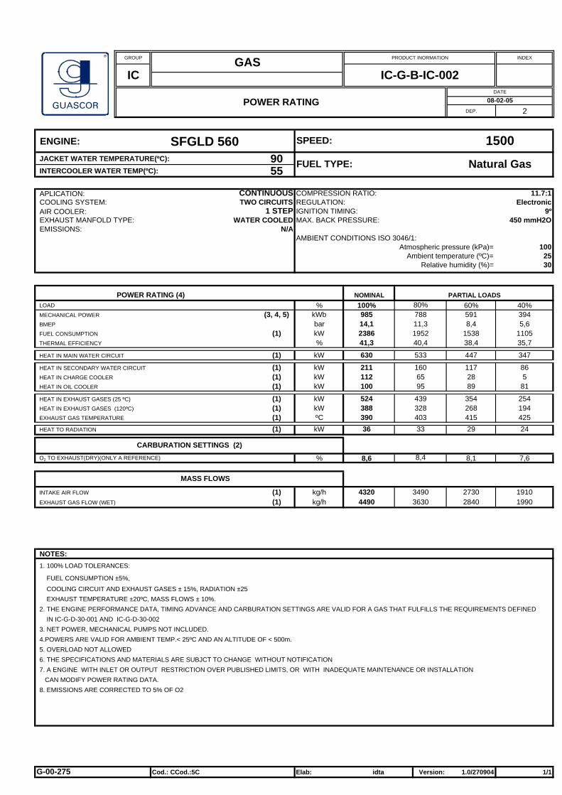
ENGINE: SFGLD 560JACKET WATER TEMPERATURE(ºC): 90INTERCOOLER WATER TEMP(ºC): 55
APLICATION: CONTINUOUS COMPRESSION RATIO: 11.7:1COOLING SYSTEM: TWO CIRCUITS REGULATION:AIR COOLER: 1 STEP IGNITION TIMING: 9ºEXHAUST MANFOLD TYPE: WATER COOLED MAX. BACK PRESSURE: 450 mmH2OEMISSIONS: N/A
AMBIENT CONDITIONS ISO 3046/1:Atmospheric pressure (kPa)= 100
Ambient temperature (ºC)= 25Relative humidity (%)= 30
LOAD % 100% 60% 40%MECHANICAL POWER (3, 4, 5) kWb 985 591 394BMEP bar 14,1 8,4 5,6FUEL CONSUMPTION (1) kW 2386 1538 1105THERMAL EFFICIENCY % 41,3 38,4 35,7
HEAT IN MAIN WATER CIRCUIT (1) kW 630 447 347
HEAT IN SECONDARY WATER CIRCUIT (1) kW 211 117 86HEAT IN CHARGE COOLER (1) kW 112 28 5HEAT IN OIL COOLER (1) kW 100 89 81
HEAT IN EXHAUST GASES (25 ºC) (1) kW 524 354 254HEAT IN EXHAUST GASES (120ºC) (1) kW 388 268 194EXHAUST GAS TEMPERATURE (1) ºC 390 415 425HEAT TO RADIATION (1) kW 36 29 24
O2 TO EXHAUST(DRY)(ONLY A REFERENCE) % 8,6 8,1 7,6
INTAKE AIR FLOW (1) kg/h 4320 2730 1910EXHAUST GAS FLOW (WET) (1) kg/h 4490 2840 1990
NOTES:1. 100% LOAD TOLERANCES:
FUEL CONSUMPTION ±5%, COOLING CIRCUIT AND EXHAUST GASES ± 15%, RADIATION ±25 EXHAUST TEMPERATURE ±20ºC, MASS FLOWS ± 10%.2. THE ENGINE PERFORMANCE DATA, TIMING ADVANCE AND CARBURATION SETTINGS ARE VALID FOR A GAS THAT FULFILLS THE REQUIREMENTS DEFINED IN IC-G-D-30-001 AND IC-G-D-30-0023. NET POWER, MECHANICAL PUMPS NOT INCLUDED.4.POWERS ARE VALID FOR AMBIENT TEMP.< 25ºC AND AN ALTITUDE OF < 500m.5. OVERLOAD NOT ALLOWED6. THE SPECIFICATIONS AND MATERIALS ARE SUBJCT TO CHANGE WITHOUT NOTIFICATION7. A ENGINE WITH INLET OR OUTPUT RESTRICTION OVER PUBLISHED LIMITS, OR WITH INADEQUATE MAINTENANCE OR INSTALLATION CAN MODIFY POWER RATING DATA.8. EMISSIONS ARE CORRECTED TO 5% OF O2
Elab: Version: 1.0/270904 1/1
34903630
160
POWER RATING (4)
CARBURATION SETTINGS (2)8,4
11,31952
65
80%
GAS
328
DATE
95
439
PARTIAL LOADSNOMINAL
788
MASS FLOWS
PRODUCT INORMATION
IC-G-B-IC-002
Cod.: CCod.:5C
403
IC
40,4
533
Electronic
idta
08-02-05POWER RATING
Natural GasFUEL TYPE:
SPEED: 1500
G-00-275
33