Embed Size (px)
Citation preview

MAN-0115 REV 0 August 13, 2009
SAFEGUARD CONTROLLER
User Manual
(Revision 4.4 – Firmware 6.03 & later)

TABLE OF CONTENTS TABLE OF CONTENTS ....................................................................................... 1 SECTION 1 ........................................................................................................... 1 IMPORTANT SAFETY ISSUES ....................................................................................... 1 1.0 GENERAL DESCRIPTION .................................................................................. 2 1.1 DATA DISPLAY SCREENS ............................................................................... 3
1.1.1 TREND SCREEN .......................................................................................................... 3 1.1.2 BAR GRAPHS SCREEN ............................................................................................... 3 1.1.3 COMBINATION SCREEN ............................................................................................. 3
1.2 SPECIFICATIONS: .............................................................................................. 4 1.2.1 DC POWER SUPPLY REQUIREMENTS ..................................................................... 4 1.2.1a 150 WATT AC – 24VDC POWER SUPPLY .................................................................. 4 1.2.2 RELAYS ........................................................................................................................ 4 1.2.3 AMBIENT TEMPERATURE RANGE ............................................................................ 4 1.2.4 HUMIDITY RANGE ....................................................................................................... 4 1.2.5 ALTITUDE ..................................................................................................................... 4 1.2.6 HOUSINGS ................................................................................................................... 5 1.2.6a NON-INTRUSIVE MAGNETIC KEYPAD ...................................................................... 5 1.2.7 APPROVALS ................................................................................................................. 5
SECTION 2 ........................................................................................................... 5 2.0 BASIC OPERATION ........................................................................................... 5 2.1 SETUP MENU CONFIGURATION ...................................................................... 6
2.1.1 CHANGING MENU VARIABLES USING THE KEYPAD .............................................. 6 2.2 CHANNEL CONFIGURATION MENUS .............................................................. 7
2.2.1 CHANNEL SETUP ENTRY MENU ............................................................................... 8 2.2.2 ALARM 1 / ALARM 2 / HORN RELAY SET-UP MENU ................................................ 8 2.2.3 ALARM 3 / FAULT ALARM MENU ................................................................................ 9 2.2.4 DATA FROM? MENU TO SET INPUT SOURCE ......................................................... 9 2.2.4a MIN / MAX RAW COUNTS MENUS ........................................................................... 10 2.2.4b MARKER MENUS ....................................................................................................... 11 2.2.4c SENSOR LIFE DETECTION (- this feature is not used at this time) .......................... 11 2.2.5 LINEARIZATION MENU .............................................................................................. 12 2.2.6 CONFIGURE MENU ................................................................................................... 12 2.2.6a EUNITS / MEASUREMENT NAME ASCII DATA FIELDS .......................................... 12 2.2.6b INPUT MEASUREMENT RANGE ............................................................................... 13 2.2.6c DECIMAL POINT RESOLUTION ................................................................................ 13 2.2.6d TURNING OFF UNUSED CHANNELS ....................................................................... 13 2.2.6e COPY DATA TO? ........................................................................................................ 13 2.2.7 CAL MODE .................................................................................................................. 14
2.3 SYSTEM CONFIGURATION MENUS ............................................................... 15 2.3.1 COMMON ALARM RELAYS 1 & 2 .............................................................................. 16 2.3.2 SG10-0195 DISCRETE RELAY “FAILSAFE” MODE .................................................. 17 2.3.3 COMMON HORN RELAY & LOCAL PIEZO ............................................................... 17 2.3.4 COMM PORT MENUS ................................................................................................ 18 2.3.5 EIGHT / SIXTEEN CHANNEL MODES ....................................................................... 19 2.3.6 SENSOR INFORMATION (this feature is not used at this time) ................................. 19
2.4 AUTHORIZATION MODE ................................................................................. 20 2.5 LCD CONTRAST ADJUSTMENT ..................................................................... 20 SECTION 3 ......................................................................................................... 21 3.0 MAIN I/O INTERFACE PCB ............................................................................. 21
Modbus Communication between SafeGuard and Digital Millennium II Series Transmitters. .. 22 3.1 INPUT / OUTPUT OPTIONAL PCB’s .............................................................. 24
3.1.1 OPTIONAL ANALOG INPUT PCB # SG10-0158 ....................................................... 24 3.1.2 OPTIONAL DISCRETE RELAY PCB # SG10-0195 ................................................... 25
MAN-0115 REV 0 August 13, 2009
3.1.6 OPTIONAL 4-20mA ANALOG OUTPUT BOARD # SG10-0167 ................................ 27 3.1.8 OPTIONAL 24VDC 150 WATT POWER SUPPLY ..................................................... 28
SECTION 4 ......................................................................................................... 29 4.0 SYSTEM DIAGNOSTICS .................................................................................. 29 SECTION 5 ......................................................................................................... 31 5.0 MODBUS RS-485 PORTS ................................................................................ 31 5.1 MODBUS SLAVE REGISTER LOCATIONS..................................................... 31 SECTION 6 ......................................................................................................... 36 6.1 SAFEGUARD PM PANEL / RACK MOUNT ENCLOSURE .............................. 36 6.2 SAFEGUARD N4 NEMA 4X WALL MOUNT FIBERGLASS ENCLOSURE .... 37 6.3 SAFEGUARD MAIN I/O & OPTION PCB FOOTPRINT DIMENSIONS ............ 39 SECTION 7 – HOW TO RETURN EQUIPMENT ................................................ 40 APPENDIX ......................................................................................................... 41 Appendix A: Electrostatic Sensitive Device (ESD) .................................................... 41
1 SafeGuard Controller User Manual MAN-0115 Rev 0
SECTION 1
IMPORTANT SAFETY ISSUES The following symbols are used in this manual to alert the user of important instrument operating issues:
!
WARNINGS:
• Shock Hazard - Disconnect or turn off power before servicing this instrument. • NEMA 4X wall mount models should be fitted with a locking mechanism after
installation to prevent access to high voltages by unauthorized personnel (see Figure 6.2).
• Only the combustible monitor portions of this instrument have been assessed by CSA for C22.2 No. 152 performance requirements.
• This equipment is suitable for use in Class I, Division 2, Groups A, B, C, and D or non-hazardous locations only.
• WARNING- EXPLOSION HAZARD- SUBSTITUTION OF COMPONENTS MAY IMPAIR SUITABILITY FOR CLASS I, DIVISION 2.
• WARNING- EXPLOSION HAZARD- DO NOT REPLACE FUSE UNLESS POWER HAS BEEN SWITCHED OFF OR THE AREA IS KNOWN TO BE NON-HAZARDOUS.
• WARNING- EXPLOSION HAZARD- DO NOT DISCONNECT EQUIPMENT UNLESS POWER HAS BEEN SWITCHED OFF OR THE AREA IS KNOWN TO BE NON-HAZARDOUS.
• Use a properly rated CERTIFIED AC power (mains) cable installed as per local or national codes
• A Certified AC power (mains) disconnect or circuit breaker should be mounted near the SafeGuard Controller and installed following applicable local and national codes. If a switch is used instead of a circuit breaker, a properly rate CERTIFIED fuse or current limiter is required to installed as per local or national codes. Markings for positions of the switch or breaker should state (I) for on and (O) for off.
• Clean only with a damp cloth without solvents.
WARNING: Read & understand contents of this manual prior to operation. Failure to do so could result in serious injury or death.
This symbol is intended to alert the user to the presence of important operating and maintenance (servicing) instructions.
This symbol is intended to alert the user to the presence of dangerous voltage within the instrument enclosure that may be sufficient magnitude to constitute a risk of electric shock.
2 SafeGuard Controller User Manual MAN-0115 Rev 0
• Equipment not used as prescribed within this manual may impair overall safety.
1.0 GENERAL DESCRIPTION The Net Safety Monitoring Inc. SafeGuard 16 channel Controller is designed to display and control alarm event switching for up to sixteen detectors (Flame detectors or transmitters with gas sensor) data points. It may also be set as an eight channel SafeGuard Controller for applications needing fewer inputs. Alarm features such as ON and OFF delays, Alarm Acknowledge, and a dedicated horn relay make the SafeGuard Controller well suited for many multi-point monitoring applications. Data may be input to the SafeGuard Controller by optional analog inputs or the standard Modbus® RTU master RS-485 port. A Modbus RTU slave RS-485 port is also standard for sending data to PC’s, PLC’s, DCS’s, or even other SafeGuard Controllers. Options such as analog I/O and discrete relays for each alarm are easily added to the addressable I2C bus. Option boards have 8 channels and therefore require 2 boards for 16 channel applications.
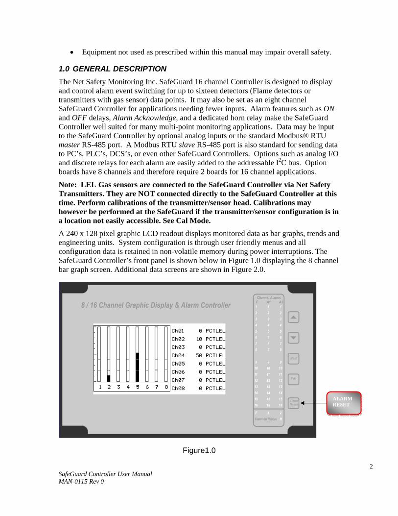
Note: LEL Gas sensors are connected to the SafeGuard Controller via Net Safety Transmitters. They are NOT connected directly to the SafeGuard Controller at this time. Perform calibrations of the transmitter/sensor head. Calibrations may however be performed at the SafeGuard if the transmitter/sensor configuration is in a location not easily accessible. See Cal Mode. A 240 x 128 pixel graphic LCD readout displays monitored data as bar graphs, trends and engineering units. System configuration is through user friendly menus and all configuration data is retained in non-volatile memory during power interruptions. The SafeGuard Controller’s front panel is shown below in Figure 1.0 displaying the 8 channel bar graph screen. Additional data screens are shown in Figure 2.0.
Figure1.0
ALARM RESET
3 SafeGuard Controller User Manual MAN-0115 Rev 0
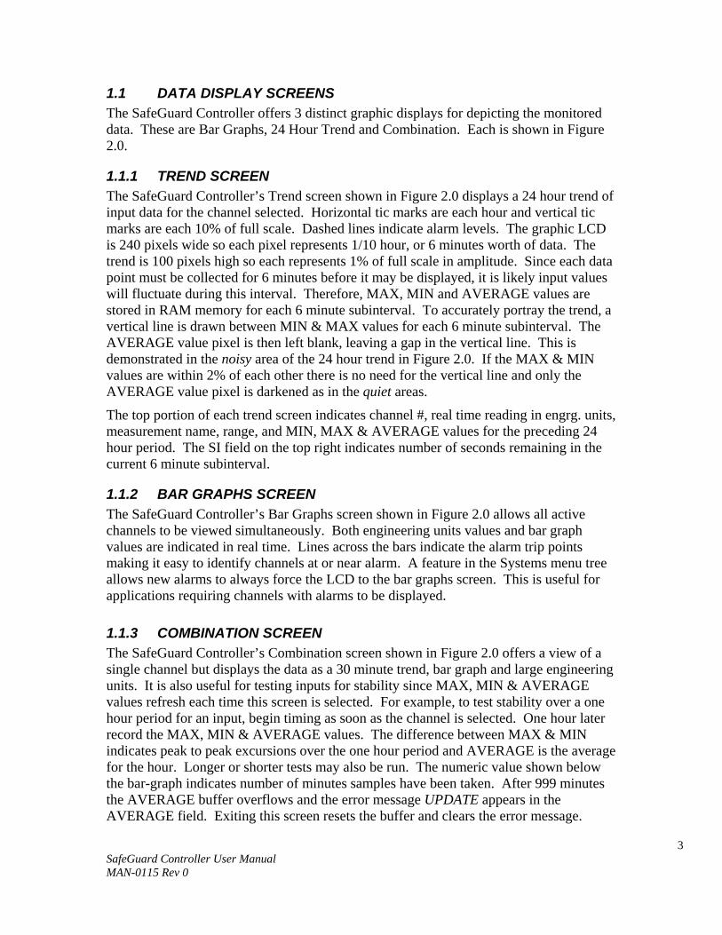
1.1 DATA DISPLAY SCREENS The SafeGuard Controller offers 3 distinct graphic displays for depicting the monitored data. These are Bar Graphs, 24 Hour Trend and Combination. Each is shown in Figure 2.0.
1.1.1 TREND SCREEN The SafeGuard Controller’s Trend screen shown in Figure 2.0 displays a 24 hour trend of input data for the channel selected. Horizontal tic marks are each hour and vertical tic marks are each 10% of full scale. Dashed lines indicate alarm levels. The graphic LCD is 240 pixels wide so each pixel represents 1/10 hour, or 6 minutes worth of data. The trend is 100 pixels high so each represents 1% of full scale in amplitude. Since each data point must be collected for 6 minutes before it may be displayed, it is likely input values will fluctuate during this interval. Therefore, MAX, MIN and AVERAGE values are stored in RAM memory for each 6 minute subinterval. To accurately portray the trend, a vertical line is drawn between MIN & MAX values for each 6 minute subinterval. The AVERAGE value pixel is then left blank, leaving a gap in the vertical line. This is demonstrated in the noisy area of the 24 hour trend in Figure 2.0. If the MAX & MIN values are within 2% of each other there is no need for the vertical line and only the AVERAGE value pixel is darkened as in the quiet areas.
The top portion of each trend screen indicates channel #, real time reading in engrg. units, measurement name, range, and MIN, MAX & AVERAGE values for the preceding 24 hour period. The SI field on the top right indicates number of seconds remaining in the current 6 minute subinterval.
1.1.2 BAR GRAPHS SCREEN The SafeGuard Controller’s Bar Graphs screen shown in Figure 2.0 allows all active channels to be viewed simultaneously. Both engineering units values and bar graph values are indicated in real time. Lines across the bars indicate the alarm trip points making it easy to identify channels at or near alarm. A feature in the Systems menu tree allows new alarms to always force the LCD to the bar graphs screen. This is useful for applications requiring channels with alarms to be displayed.
1.1.3 COMBINATION SCREEN The SafeGuard Controller’s Combination screen shown in Figure 2.0 offers a view of a single channel but displays the data as a 30 minute trend, bar graph and large engineering units. It is also useful for testing inputs for stability since MAX, MIN & AVERAGE values refresh each time this screen is selected. For example, to test stability over a one hour period for an input, begin timing as soon as the channel is selected. One hour later record the MAX, MIN & AVERAGE values. The difference between MAX & MIN indicates peak to peak excursions over the one hour period and AVERAGE is the average for the hour. Longer or shorter tests may also be run. The numeric value shown below the bar-graph indicates number of minutes samples have been taken. After 999 minutes the AVERAGE buffer overflows and the error message UPDATE appears in the AVERAGE field. Exiting this screen resets the buffer and clears the error message.

4 SafeGuard Controller User Manual MAN-0115 Rev 0
1.2 SPECIFICATIONS:
1.2.1 DC POWER SUPPLY REQUIREMENTS Standard SafeGuard Controller power requirements are 10-30VDC @ 3 watts applied to terminals 9 & 11 of TB2 on the standard I/O PCB (see section 3.0). Optional features increase power consumption as described below: • Discrete Relay PCB option; add 2 watts per PCB (assumes all 8 relays are energized). • Analog Input PCB option; add 1/2 watt. • 4-20mA Output PCB option; add 1 watt. • TB2 terminals 10 & 12 of the standard I/O PCB provide a maximum of 500mA fused
output power for powering of auxiliary external devices such as relays, lamps or transmitters. Power consumed from these terminals should be considered when calculating system power consumption.
When wiring transmitters (detectors) to the SafeGuard Controller refer to 3.1.1 Optional Analog Input PCB # SG10-0158 and Figure 3.3.
1.2.1a 150 WATT AC – 24VDC POWER SUPPLY *110-120 VAC @3.2A max *220-240VAC @ 1.6A max * A slide switch on the front of the power supply selects AC input range. The SG10-0172 150 watt power supply (Figure 3.6) is for powering the SafeGuard Controller and up to 16 detectors. A minimum of 5 watts per channel is available for powering of external transmitters.
1.2.2 RELAYS Common relays are standard and menus provide voting logic for ALARM 1, ALARM 2, FAULT and HORN. Discrete relays are optional. Relays are Form C dry contacts and are rated at 5 Amp for 28 VDC and 250 ~VAC RESISTIVE loads.
IMPORTANT: Appropriate diode (DC loads) or MOV (AC loads) snubber devices must be installed with inductive loads to prevent RFI noise spikes. Relay wiring should be kept separate from low level signal wiring.
1.2.3 AMBIENT TEMPERATURE RANGE -25 to +50 degrees C
1.2.4 HUMIDITY RANGE 0 to 90% R. H. Non-Condensing.
1.2.5 ALTITUDE Recommended up to 2000 meters
!

5 SafeGuard Controller User Manual MAN-0115 Rev 0
1.2.6 HOUSINGS • *General purpose panel mount weighing 7 lbs and including hardware for 19” rack
mounting (Figure 6.1). • *NEMA 4X wall mount in fiberglass enclosure weighing 17 lbs (Figure 6.2).
1.2.6a NON-INTRUSIVE MAGNETIC KEYPAD The SafeGuard Controller’s operator interface includes five front panel touch keys. A magnetic keypad option offers these five keys with adjacent magnetic keys. This option is included as a standard feature. It is useful in applications where it may be inconvenient to open the enclosure’s door to access the touch keypad.
1.2.7 APPROVALS CSA C22.2 No 1010.1 and ISA S82.02; CSA C22.2 No 152 for combustibles; UL 1604 / C22.2 No 213 (Div 2 Groups A,B,C,D); EN55011 & EN61000 (CE Mark). CSA File # = 219995 and may be seen at: CSA-International.org.
SECTION 2
2.0 BASIC OPERATION The SafeGuard Controller offers 3 graphic screens for viewing monitored data and a Set-Up menu screen for operator interface to configuration menus. They are shown below in Figure 2.0. The Bar Graphs screen allows viewing of all active channels simultaneously. The Trend screen displays a 24 hour trend one channel at a time. The Combination screen displays a bar graph, large engineering units and a 30 minute trend one channel at a time. Input channels may be displayed in sequence with the UP/DOWN keys. The NEXT key switches between the 3 graphic data screens. When SafeGuard power is applied, the graphic LCD returns to the screen active when power was last removed.
Setup menus are entered by pressing EDIT from any data screen, and scrolling to the desired menu using the UP/DOWN keys. Pressing EDIT again enters the selected menu’s tree of variables. This Setup mode may be exited manually by pressing NEXT, or automatically when no keys are pressed for 5 minutes. Alarm relays and front panel alarm LED indicators remain active during the Setup mode. An AUTHORIZE menu offers a password feature to prevent tampering with the SafeGuard Controller’s parameters.
6 SafeGuard Controller User Manual MAN-0115 Rev 0
Figure 2.0
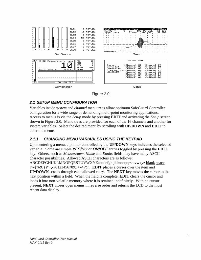
2.1 SETUP MENU CONFIGURATION Variables inside system and channel menu trees allow optimum SafeGuard Controller configuration for a wide range of demanding multi-point monitoring applications. Access to menus is via the Setup mode by pressing EDIT and activating the Setup screen shown in Figure 2.0. Menu trees are provided for each of the 16 channels and another for system variables. Select the desired menu by scrolling with UP/DOWN and EDIT to enter the menus.
2.1.1 CHANGING MENU VARIABLES USING THE KEYPAD Upon entering a menu, a pointer controlled by the UP/DOWN keys indicates the selected variable. Some are simple YES/NO or ON/OFF entries toggled by pressing the EDIT key. Others, such as Measurement Name and Eunits fields may have many ASCII character possibilities. Allowed ASCII characters are as follows: ABCDEFGHIJKLMNOPQRSTUVWXYZabcdefghijklmnopqrstuvwxyz blank space !"#$%&`()*+,-./0123456789:;<=>?@. EDIT places a cursor over the item and UP/DOWN scrolls through each allowed entry. The NEXT key moves the cursor to the next position within a field. When the field is complete, EDIT clears the cursor and loads it into non-volatile memory where it is retained indefinitely. With no cursor present, NEXT closes open menus in reverse order and returns the LCD to the most recent data display.
7 SafeGuard Controller User Manual MAN-0115 Rev 0
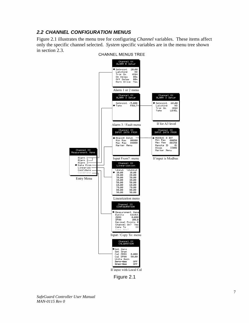
2.2 CHANNEL CONFIGURATION MENUS Figure 2.1 illustrates the menu tree for configuring Channel variables. These items affect only the specific channel selected. System specific variables are in the menu tree shown in section 2.3.
Figure 2.1
8 SafeGuard Controller User Manual MAN-0115 Rev 0
2.2.1 CHANNEL SETUP ENTRY MENU The entry menu shown on the left side of Figure 2.1 allows access to all configuration variables for the selected channel. These are Alarm 1, Alarm 2, Alarm 3, Data From? Linearize, Configure and Calibrate.
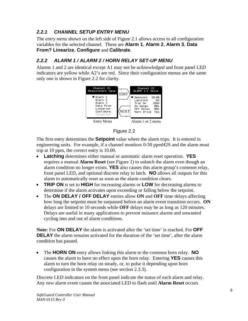
2.2.2 ALARM 1 / ALARM 2 / HORN RELAY SET-UP MENU Alarms 1 and 2 are identical except A1 may not be acknowledged and front panel LED indicators are yellow while A2’s are red. Since their configuration menus are the same only one is shown in Figure 2.2 for clarity.
Figure 2.2 The first entry determines the Setpoint value where the alarm trips. It is entered in engineering units. For example, if a channel monitors 0-50 ppmH2S and the alarm must trip at 10 ppm, the correct entry is 10.00. • Latching determines either manual or automatic alarm reset operation. YES
requires a manual Alarm Reset (see Figure 1) to unlatch the alarm even though an alarm condition no longer exists. YES also causes this alarm group’s common relay, front panel LED, and optional discrete relay to latch. NO allows all outputs for this alarm to automatically reset as soon as the alarm condition clears.
• TRIP ON is set to HIGH for increasing alarms or LOW for decreasing alarms to determine if the alarm activates upon exceeding or falling below the setpoint.
• The ON DELAY / OFF DELAY entries allow ON and OFF time delays affecting how long the setpoint must be surpassed before an alarm event transition occurs. ON delays are limited to 10 seconds while OFF delays may be as long as 120 minutes. Delays are useful in many applications to prevent nuisance alarms and unwanted cycling into and out of alarm conditions.
Note: For ON DELAY the alarm is activated after the ‘set time’ is reached. For OFF DELAY the alarm remains activated for the duration of the ‘set time’, after the alarm condition has passed. • The HORN ON entry allows linking this alarm to the common horn relay. NO
causes the alarm to have no effect upon the horn relay. Entering YES causes this alarm to turn the horn relay on steady, or, to pulse it depending upon horn configuration in the system menu (see section 2.3.3).
Discrete LED indicators on the front panel indicate the status of each alarm and relay. Any new alarm event causes the associated LED to flash until Alarm Reset occurs
9 SafeGuard Controller User Manual MAN-0115 Rev 0
causing an acknowledged steady on condition. Operators should recognize new alarms by a flashing LED. Alarm Reset also acknowledges, or deactivates, the horn relay until another new alarm occurs.
All relays are rated at 5 Amp for 28 VDC and 250 ~VAC RESISTIVE loads. IMPORTANT: Appropriate diode (DC loads) or MOV (AC loads) snubber devices must be installed with inductive loads to prevent RFI noise spikes. Relay
wiring should be kept separate from low level signal wiring.
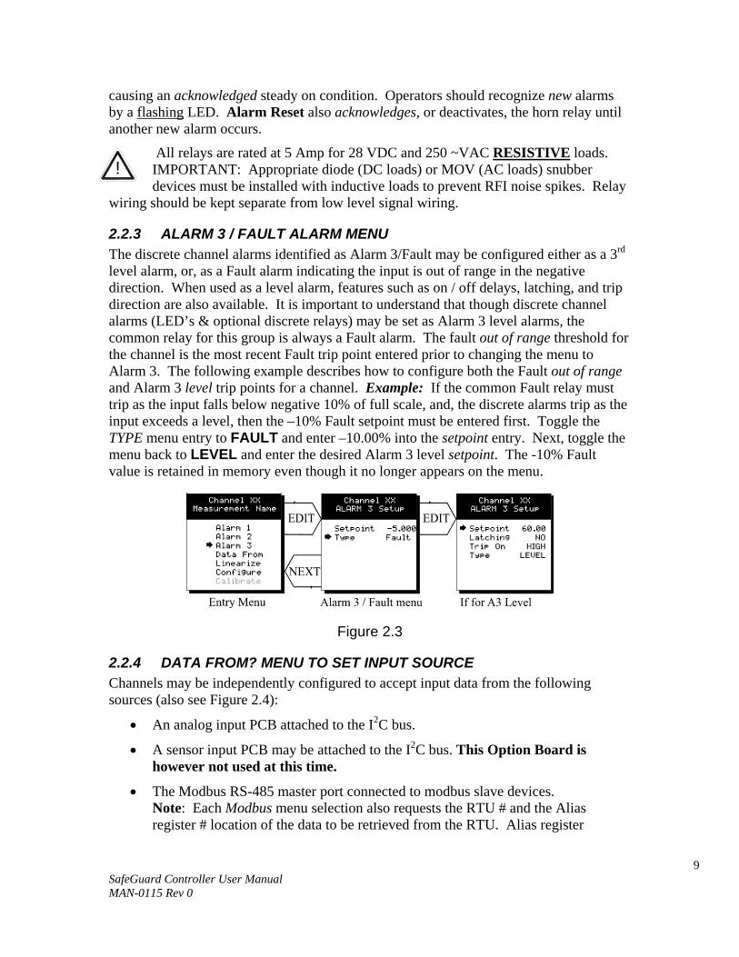
2.2.3 ALARM 3 / FAULT ALARM MENU The discrete channel alarms identified as Alarm 3/Fault may be configured either as a 3rd level alarm, or, as a Fault alarm indicating the input is out of range in the negative direction. When used as a level alarm, features such as on / off delays, latching, and trip direction are also available. It is important to understand that though discrete channel alarms (LED’s & optional discrete relays) may be set as Alarm 3 level alarms, the common relay for this group is always a Fault alarm. The fault out of range threshold for the channel is the most recent Fault trip point entered prior to changing the menu to Alarm 3. The following example describes how to configure both the Fault out of range and Alarm 3 level trip points for a channel. Example: If the common Fault relay must trip as the input falls below negative 10% of full scale, and, the discrete alarms trip as the input exceeds a level, then the –10% Fault setpoint must be entered first. Toggle the TYPE menu entry to FAULT and enter –10.00% into the setpoint entry. Next, toggle the menu back to LEVEL and enter the desired Alarm 3 level setpoint. The -10% Fault value is retained in memory even though it no longer appears on the menu.
Figure 2.3
2.2.4 DATA FROM? MENU TO SET INPUT SOURCE Channels may be independently configured to accept input data from the following sources (also see Figure 2.4):
• An analog input PCB attached to the I2C bus.
• A sensor input PCB may be attached to the I2C bus. This Option Board is however not used at this time.
• The Modbus RS-485 master port connected to modbus slave devices. Note: Each Modbus menu selection also requests the RTU # and the Alias register # location of the data to be retrieved from the RTU. Alias register
!
10 SafeGuard Controller User Manual MAN-0115 Rev 0
numbers define the location of the variable representing the input value and must be obtained from the manufacturer of the Modbus RTU device.
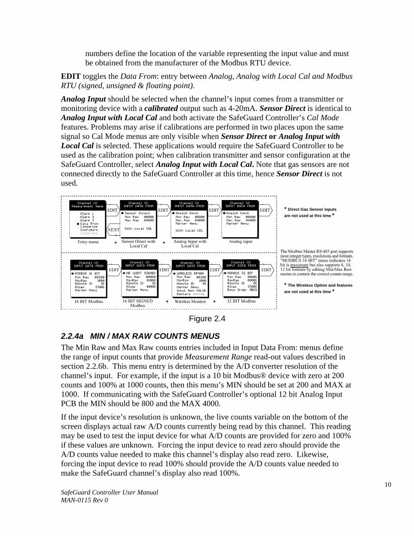
EDIT toggles the Data From: entry between Analog, Analog with Local Cal and Modbus RTU (signed, unsigned & floating point).
Analog Input should be selected when the channel’s input comes from a transmitter or monitoring device with a calibrated output such as 4-20mA. Sensor Direct is identical to Analog Input with Local Cal and both activate the SafeGuard Controller’s Cal Mode features. Problems may arise if calibrations are performed in two places upon the same signal so Cal Mode menus are only visible when Sensor Direct or Analog Input with Local Cal is selected. These applications would require the SafeGuard Controller to be used as the calibration point; when calibration transmitter and sensor configuration at the SafeGuard Controller, select Analog Input with Local Cal. Note that gas sensors are not connected directly to the SafeGuard Controller at this time, hence Sensor Direct is not used.
Figure 2.4
2.2.4a MIN / MAX RAW COUNTS MENUS The Min Raw and Max Raw counts entries included in Input Data From: menus define the range of input counts that provide Measurement Range read-out values described in section 2.2.6b. This menu entry is determined by the A/D converter resolution of the channel’s input. For example, if the input is a 10 bit Modbus® device with zero at 200 counts and 100% at 1000 counts, then this menu’s MIN should be set at 200 and MAX at 1000. If communicating with the SafeGuard Controller’s optional 12 bit Analog Input PCB the MIN should be 800 and the MAX 4000.
If the input device’s resolution is unknown, the live counts variable on the bottom of the screen displays actual raw A/D counts currently being read by this channel. This reading may be used to test the input device for what A/D counts are provided for zero and 100% if these values are unknown. Forcing the input device to read zero should provide the A/D counts value needed to make this channel’s display also read zero. Likewise, forcing the input device to read 100% should provide the A/D counts value needed to make the SafeGuard channel’s display also read 100%.
* Direct Gas Sensor inputs are not used at this time *
* The Wireless Option and features are not used at this time *
* *
* *
11 SafeGuard Controller User Manual MAN-0115 Rev 0
If Modbus 32 BIT is selected, a Byte Order entry appears at the bottom of the menu. This determines WORD and BYTE alignment of data at the remote Modbus transmitter when sending its 4 byte IEEE Floating Point values. With the pointer on this entry, the EDIT key toggles between the 4 possible modes. Min / Max Raw values are not used in this mode.
Note: Each Data From: item has a matching default Min/Max counts value of 20% to 100% with ± 5% over/under range applied. If the default value is incorrect for the input device it should be edited.
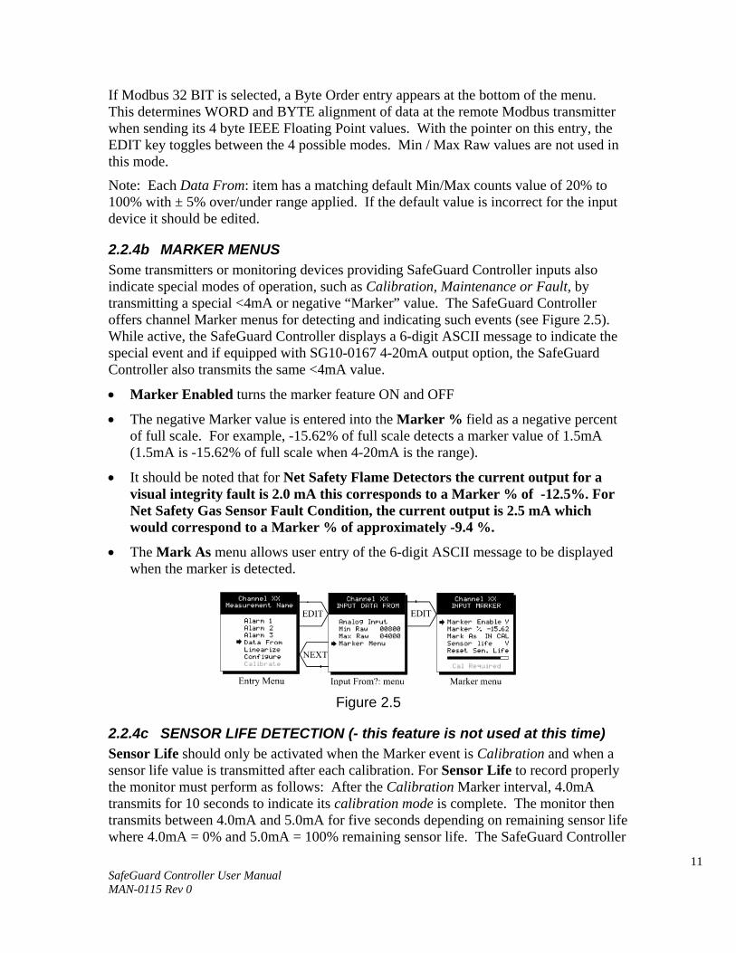
2.2.4b MARKER MENUS Some transmitters or monitoring devices providing SafeGuard Controller inputs also indicate special modes of operation, such as Calibration, Maintenance or Fault, by transmitting a special <4mA or negative “Marker” value. The SafeGuard Controller offers channel Marker menus for detecting and indicating such events (see Figure 2.5). While active, the SafeGuard Controller displays a 6-digit ASCII message to indicate the special event and if equipped with SG10-0167 4-20mA output option, the SafeGuard Controller also transmits the same <4mA value.
• Marker Enabled turns the marker feature ON and OFF
• The negative Marker value is entered into the Marker % field as a negative percent of full scale. For example, -15.62% of full scale detects a marker value of 1.5mA (1.5mA is -15.62% of full scale when 4-20mA is the range).
• It should be noted that for Net Safety Flame Detectors the current output for a visual integrity fault is 2.0 mA this corresponds to a Marker % of -12.5%. For Net Safety Gas Sensor Fault Condition, the current output is 2.5 mA which would correspond to a Marker % of approximately -9.4 %.
• The Mark As menu allows user entry of the 6-digit ASCII message to be displayed when the marker is detected.
Figure 2.5
2.2.4c SENSOR LIFE DETECTION (- this feature is not used at this time) Sensor Life should only be activated when the Marker event is Calibration and when a sensor life value is transmitted after each calibration. For Sensor Life to record properly the monitor must perform as follows: After the Calibration Marker interval, 4.0mA transmits for 10 seconds to indicate its calibration mode is complete. The monitor then transmits between 4.0mA and 5.0mA for five seconds depending on remaining sensor life where 4.0mA = 0% and 5.0mA = 100% remaining sensor life. The SafeGuard Controller
12 SafeGuard Controller User Manual MAN-0115 Rev 0
reads this value and records it as the channel’s Sensor Life. Sensor Life is stored in the SafeGuard Controller’s modbus database and displayed as a bar-graph in the Sensor Info screen (see section 2.3.6). It is a useful tool for planning sensor replacement schedules.
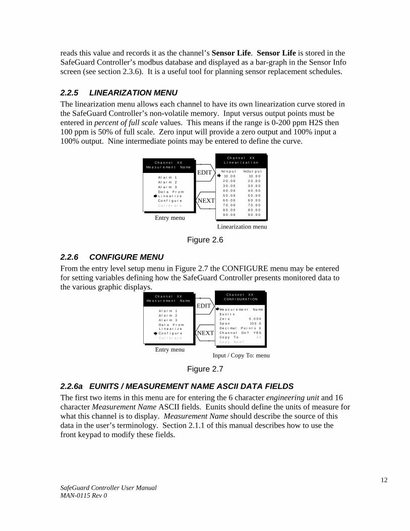
2.2.5 LINEARIZATION MENU The linearization menu allows each channel to have its own linearization curve stored in the SafeGuard Controller’s non-volatile memory. Input versus output points must be entered in percent of full scale values. This means if the range is 0-200 ppm H2S then 100 ppm is 50% of full scale. Zero input will provide a zero output and 100% input a 100% output. Nine intermediate points may be entered to define the curve.
EDIT
NEXT
Entry menu
C h a n n e l X XMe a s u r e me n t Na me
Linearization menu
C h a n n e l X XL i n e a r i z a t i o n
%I n p u t %Ou t p u t10 . 0 0
2 0 . 0 03 0 . 0 04 0 . 0 05 0 . 0 06 0 . 0 07 0 . 0 08 0 . 0 09 0 . 0 0
10 . 0 02 0 . 0 03 0 . 0 04 0 . 0 05 0 . 0 06 0 . 0 07 0 . 0 08 0 . 0 09 0 . 0 0
A l a r m 1A l a r m 2A l a r m 3Da t a F r o m
Ca l i b r a t e
L i n e a r i z eC o n f i g u r e
Figure 2.6
2.2.6 CONFIGURE MENU From the entry level setup menu in Figure 2.7 the CONFIGURE menu may be entered for setting variables defining how the SafeGuard Controller presents monitored data to the various graphic displays.
Figure 2.7
2.2.6a EUNITS / MEASUREMENT NAME ASCII DATA FIELDS The first two items in this menu are for entering the 6 character engineering unit and 16 character Measurement Name ASCII fields. Eunits should define the units of measure for what this channel is to display. Measurement Name should describe the source of this data in the user’s terminology. Section 2.1.1 of this manual describes how to use the front keypad to modify these fields.
Entry menu
C h a n n e l X XMe a s u r e me n t Na me
A l a r m 1A l a r m 2A l a r m 3Da t a F r o m
C a l i b r a t e
L i n e a r i z eC o n f i g u r e
EDIT
NEXT
Input / Copy To: menu
C h a n n e l X XCON F I GU R A T I ON
Me a s u r e me n t Na meE u n i t sZ e r oS p a nDe c i ma l P o i n t s
P C T L E L0 . 0 0 0
Co p y N o w?
10 0 . 0
Ch a n n e l On ?0
Y E SCo p y T o X X
13 SafeGuard Controller User Manual MAN-0115 Rev 0
2.2.6b INPUT MEASUREMENT RANGE The ZERO / SPAN entries allow configuration of the measurement range displayed by the channel. Measurement Range works along with A/D Counts menus, described in section 2.2.4a, to define the range of the input signal’s engineering units. For example, if a channel’s input is 4-20mA from a transmitter monitoring 0 to 10ppm H2S, then the Zero value should equal 0.000 and the Span value equal 10.00. The six ASCII engineering units previously entered are automatically displayed at the top of each menu as a reminder. Four digits must appear in this entry so trailing 0’s may appear here that are not displayed on other data screens.
2.2.6c DECIMAL POINT RESOLUTION Resolution of displayed channel values is configured in this menu by setting the number digits trailing the decimal point. Values are limited to a maximum of four digits, and a polarity sign. An auto-ranging feature displays the highest resolution allowed by this menu’s decimal point entry. For example, if three decimal points are entered, and the range is 0 to 100ppm, the reading will be 0.000 at 0ppm and 100.0 at 100ppm. However, this may be undesirable due to the high resolution at zero unless the detector’s output is extremely stable. If decimal points are limited to one, the 0ppm reading becomes 0.0 and the 100ppm reading remains 100.0. Resolution may be limited further by setting decimal points to 0. In the above example, this would cause 0ppm to display 0 and 100ppm to display 100.
2.2.6d TURNING OFF UNUSED CHANNELS The Channel On? entry determines if this channel is to be utilized. Turning it off will cause the SafeGuard Controller to never process inputs applied to this channel and no alarms will be tripped or data displayed. Inactive channels have a line drawn through them on the Setup screen as indicated by channels 15 & 16 in Figure 2.0. If less than 9 channels are to be activated, the SafeGuard Controller may be set for 8 channel mode, deactivating channels 9-16. This is done in the System Setup menu described in section 2.3. The SafeGuard Controller will only allow 15 channels to be turned off. At least one channel must remain on.
2.2.6e COPY DATA TO? This menu simplifies the Setup procedure by allowing similar channels to be copied from one to another. For example, if all channels are identical except for the Measurement Name entry, channel 1 could be configured and copied to channels 2 – 16. Only Measurement Name then must be configured on channels 2 – 16. Use EDIT to increment channel numbers and UP/DN to point to Copy Now? Press EDIT once more to copy.
14 SafeGuard Controller User Manual MAN-0115 Rev 0
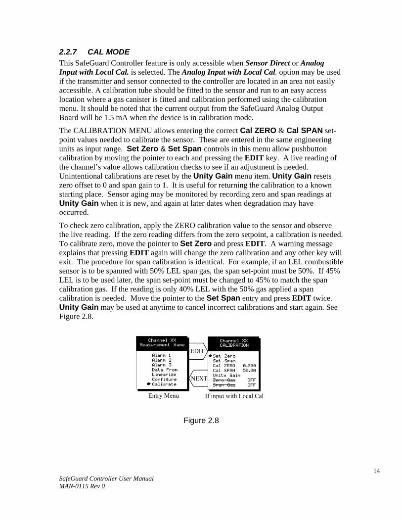
2.2.7 CAL MODE This SafeGuard Controller feature is only accessible when Sensor Direct or Analog Input with Local Cal. is selected. The Analog Input with Local Cal. option may be used if the transmitter and sensor connected to the controller are located in an area not easily accessible. A calibration tube should be fitted to the sensor and run to an easy access location where a gas canister is fitted and calibration performed using the calibration menu. It should be noted that the current output from the SafeGuard Analog Output Board will be 1.5 mA when the device is in calibration mode.
The CALIBRATION MENU allows entering the correct Cal ZERO & Cal SPAN set-point values needed to calibrate the sensor. These are entered in the same engineering units as input range. Set Zero & Set Span controls in this menu allow pushbutton calibration by moving the pointer to each and pressing the EDIT key. A live reading of the channel’s value allows calibration checks to see if an adjustment is needed. Unintentional calibrations are reset by the Unity Gain menu item. Unity Gain resets zero offset to 0 and span gain to 1. It is useful for returning the calibration to a known starting place. Sensor aging may be monitored by recording zero and span readings at Unity Gain when it is new, and again at later dates when degradation may have occurred.
To check zero calibration, apply the ZERO calibration value to the sensor and observe the live reading. If the zero reading differs from the zero setpoint, a calibration is needed. To calibrate zero, move the pointer to Set Zero and press EDIT. A warning message explains that pressing EDIT again will change the zero calibration and any other key will exit. The procedure for span calibration is identical. For example, if an LEL combustible sensor is to be spanned with 50% LEL span gas, the span set-point must be 50%. If 45% LEL is to be used later, the span set-point must be changed to 45% to match the span calibration gas. If the reading is only 40% LEL with the 50% gas applied a span calibration is needed. Move the pointer to the Set Span entry and press EDIT twice. Unity Gain may be used at anytime to cancel incorrect calibrations and start again. See Figure 2.8.
Figure 2.8
15 SafeGuard Controller User Manual MAN-0115 Rev 0
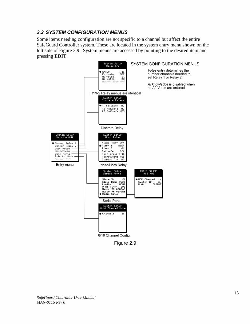
2.3 SYSTEM CONFIGURATION MENUS Some items needing configuration are not specific to a channel but affect the entire SafeGuard Controller system. These are located in the system entry menu shown on the left side of Figure 2.9. System menus are accessed by pointing to the desired item and pressing EDIT.
Figure 2.9
16 SafeGuard Controller User Manual MAN-0115 Rev 0
2.3.1 COMMON ALARM RELAYS 1 & 2 READ THIS SECTION CAREFULLY AND TEST ALL SETTINGS BY SIMULATING INPUT CONDITIONS THAT SHOULD ACTIVATE THESE ALARM RELAYS!
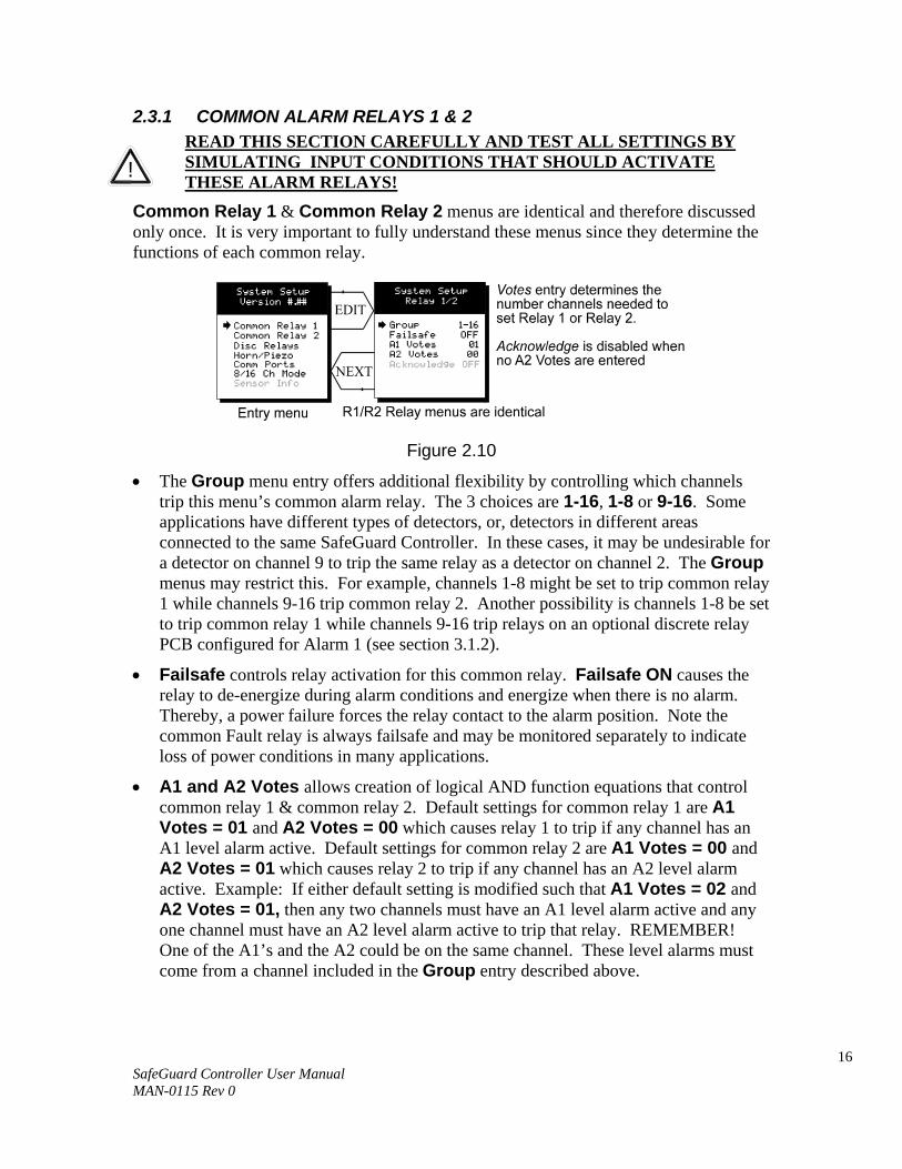
Common Relay 1 & Common Relay 2 menus are identical and therefore discussed only once. It is very important to fully understand these menus since they determine the functions of each common relay.
Figure 2.10
• The Group menu entry offers additional flexibility by controlling which channels trip this menu’s common alarm relay. The 3 choices are 1-16, 1-8 or 9-16. Some applications have different types of detectors, or, detectors in different areas connected to the same SafeGuard Controller. In these cases, it may be undesirable for a detector on channel 9 to trip the same relay as a detector on channel 2. The Group menus may restrict this. For example, channels 1-8 might be set to trip common relay 1 while channels 9-16 trip common relay 2. Another possibility is channels 1-8 be set to trip common relay 1 while channels 9-16 trip relays on an optional discrete relay PCB configured for Alarm 1 (see section 3.1.2).
• Failsafe controls relay activation for this common relay. Failsafe ON causes the relay to de-energize during alarm conditions and energize when there is no alarm. Thereby, a power failure forces the relay contact to the alarm position. Note the common Fault relay is always failsafe and may be monitored separately to indicate loss of power conditions in many applications.
• A1 and A2 Votes allows creation of logical AND function equations that control common relay 1 & common relay 2. Default settings for common relay 1 are A1 Votes = 01 and A2 Votes = 00 which causes relay 1 to trip if any channel has an A1 level alarm active. Default settings for common relay 2 are A1 Votes = 00 and A2 Votes = 01 which causes relay 2 to trip if any channel has an A2 level alarm active. Example: If either default setting is modified such that A1 Votes = 02 and A2 Votes = 01, then any two channels must have an A1 level alarm active and any one channel must have an A2 level alarm active to trip that relay. REMEMBER! One of the A1’s and the A2 could be on the same channel. These level alarms must come from a channel included in the Group entry described above.
!
17 SafeGuard Controller User Manual MAN-0115 Rev 0
• Turning Acknowledge ON (not available on Alarm 1) allows the common relay to be deactivated during alarm conditions by an Alarm Reset. This is useful if an audible device is being driven by the relay.
All relays are rated at 5 Amp for 28 VDC and 250 ~VAC RESISTIVE loads. IMPORTANT: Appropriate diode (DC loads) or MOV (AC loads) snubber devices must be installed with inductive loads to prevent RFI noise spikes. Relay wiring should be kept separate from low level signal wiring.
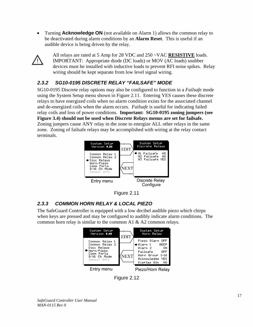
2.3.2 SG10-0195 DISCRETE RELAY “FAILSAFE” MODE SG10-0195 Discrete relay options may also be configured to function in a Failsafe mode using the System Setup menu shown in Figure 2.11. Entering YES causes these discrete relays to have energized coils when no alarm condition exists for the associated channel and de-energized coils when the alarm occurs. Failsafe is useful for indicating failed relay coils and loss of power conditions. Important: SG10-0195 zoning jumpers (see Figure 3.4) should not be used when Discrete Relays menus are set for failsafe. Zoning jumpers cause ANY relay in the zone to energize ALL other relays in the same zone. Zoning of failsafe relays may be accomplished with wiring at the relay contact terminals.
Figure 2.11
2.3.3 COMMON HORN RELAY & LOCAL PIEZO The SafeGuard Controller is equipped with a low decibel audible piezo which chirps when keys are pressed and may be configured to audibly indicate alarm conditions. The common horn relay is similar to the common A1 & A2 common relays.
Figure 2.12
!
18 SafeGuard Controller User Manual MAN-0115 Rev 0
• Turning Piezo Alarm ON causes the audible piezo to duplicate the action of the horn relay. This feature may be used to provide a low decibel indication of the status of the system’s horn.
• Alarm 1 & Alarm 2 menus control how the alarm level from each channel will affect the common horn relay. Choices are OFF, ON or BEEP (one Hz. Pulsating). As an example, A2 conditions might pulse the horn (BEEP) and A1 conditions cause a steady horn (ON). Any other combination of these 3 choices is possible for A1 and A2 levels affecting the horn relay. This feature is very useful since it allows the horn relay to serve as another level A1, level A2, or both; for channels 1-16, 1-8 or 9-16. Individual channel alarms may also be configured to not affect the Horn relay on a channel by channel basis (see section 2.2.2).
• Failsafe & Horn Group menu entries are identical to the descriptions for menus Common Relay 1 & Common Relay 2 in section 2.3.1.
• Turning Acknowledge OFF allows the common Horn relay to drive devices other than horns or sirens such as a light or a fan.
• Display Alm YES forces the LCD to display the Bar Graphs screen upon any new alarm. This feature is offered to satisfy applications requiring channels in alarm to be displayed automatically (all channels are displayed on the Bar Graphs screen).
2.3.4 COMM PORT MENUS The system Comm Port menu allows setting RTU Slave ID address, Slave Baud rate, Parity and UART Timer for the comm2 slave Modbus serial port (comm1 master port ID settings are per channel as described in section 2.2.4). This slave port may be used to transfer the SafeGuard Controller data to a host device such as a PC, PLC, DCS or even another SafeGuard Controller. The slave port is addressable, allowing many SafeGuard Controllers to be connected to a single RS-485 cable. The UART Timer setting is disabled with 00 seconds entered. Entering a value causes the comm2 slave Modbus serial port to reinitialize if no modbus query is processed within this time period. This ensures against serial port lockup. Section 5 of this manual provides important information describing how to interface to the SafeGuard Controller’s Modbus slave port.
The Mastr TO (master time out) and Mastr PR (master poll rate) menu items affect the SafeGuard Controller’s master Modbus port. Time out sets length of time in milliseconds before a communications error. Three consecutive timeout errors must occur before a communication error is indicated. This item is useful for optimizing throughput to the SafeGuard Controller from other slave RTU’s. Poll Rate sets frequency of data requests to the RTU’s in milliseconds. This is useful when an RTU is limited in how fast it may respond to consecutive data requests.
19 SafeGuard Controller User Manual MAN-0115 Rev 0
Figure 2.13
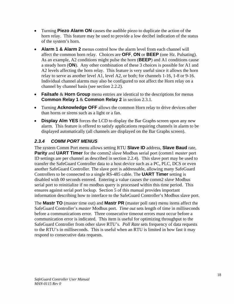
2.3.5 EIGHT / SIXTEEN CHANNEL MODES The system menu allows setting the SafeGuard Controller to accept either 8, or, 16 channels. If 8 channels are selected by this menu they are channels 1-8 and 9-16 are disabled. One way the SafeGuard Controller cost is kept low is Input / Output option PCB’s are arranged into groups of 8 channels. Therefore, users with less than 9 channels require only 1 PCB and do not pay for I/O hardware for 16 channels. If more than 8 channels are needed a second I/O option PCB may be required.
Figure 2.14
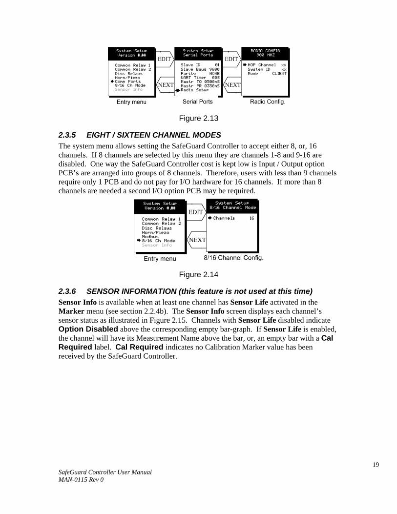
2.3.6 SENSOR INFORMATION (this feature is not used at this time) Sensor Info is available when at least one channel has Sensor Life activated in the Marker menu (see section 2.2.4b). The Sensor Info screen displays each channel’s sensor status as illustrated in Figure 2.15. Channels with Sensor Life disabled indicate Option Disabled above the corresponding empty bar-graph. If Sensor Life is enabled, the channel will have its Measurement Name above the bar, or, an empty bar with a Cal Required label. Cal Required indicates no Calibration Marker value has been received by the SafeGuard Controller.
20 SafeGuard Controller User Manual MAN-0115 Rev 0
Figure 2.15
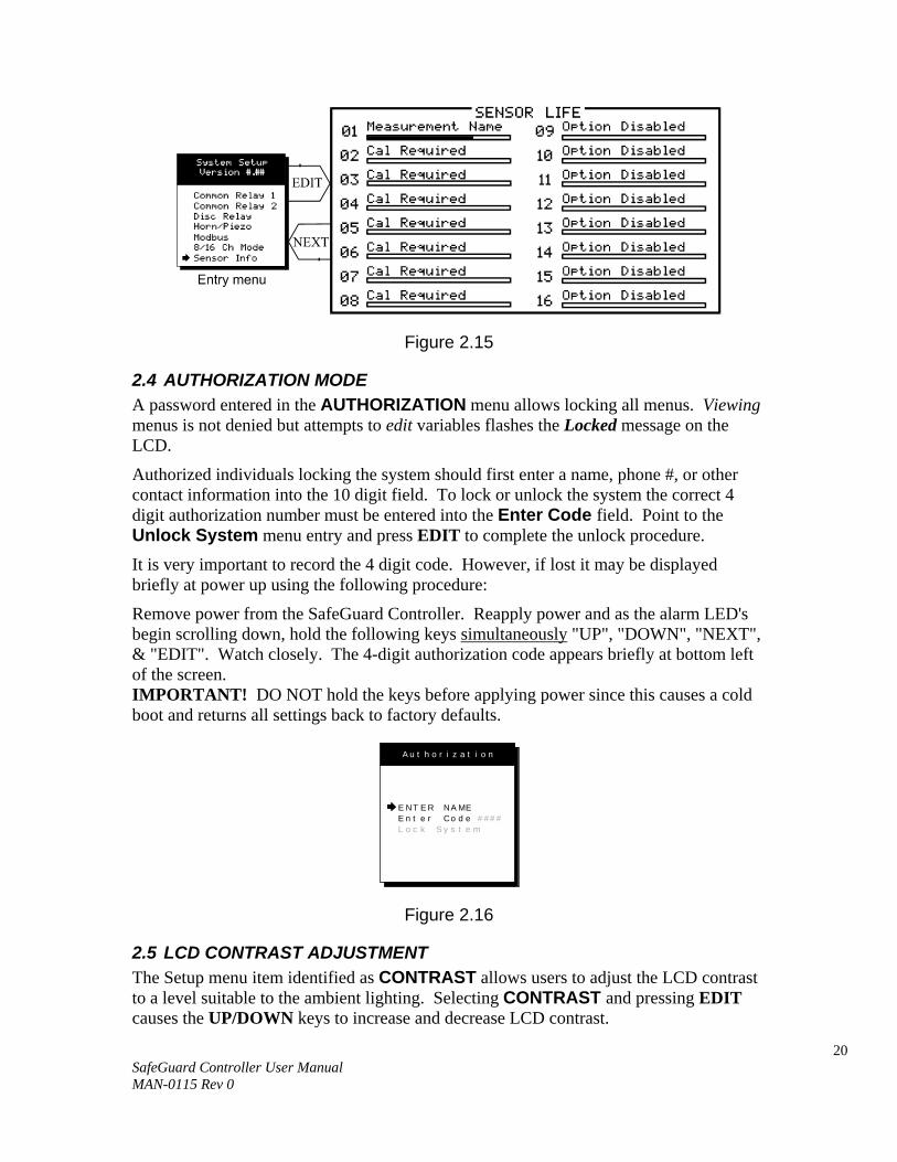
2.4 AUTHORIZATION MODE A password entered in the AUTHORIZATION menu allows locking all menus. Viewing menus is not denied but attempts to edit variables flashes the Locked message on the LCD.
Authorized individuals locking the system should first enter a name, phone #, or other contact information into the 10 digit field. To lock or unlock the system the correct 4 digit authorization number must be entered into the Enter Code field. Point to the Unlock System menu entry and press EDIT to complete the unlock procedure.
It is very important to record the 4 digit code. However, if lost it may be displayed briefly at power up using the following procedure:
Remove power from the SafeGuard Controller. Reapply power and as the alarm LED's begin scrolling down, hold the following keys simultaneously "UP", "DOWN", "NEXT", & "EDIT". Watch closely. The 4-digit authorization code appears briefly at bottom left of the screen. IMPORTANT! DO NOT hold the keys before applying power since this causes a cold boot and returns all settings back to factory defaults.
A u t h o r i z a t i o n
E NT E R NA MEE n t e r Co d eL o c k S y s t e m
# # # #
Figure 2.16
2.5 LCD CONTRAST ADJUSTMENT The Setup menu item identified as CONTRAST allows users to adjust the LCD contrast to a level suitable to the ambient lighting. Selecting CONTRAST and pressing EDIT causes the UP/DOWN keys to increase and decrease LCD contrast.
21 SafeGuard Controller User Manual MAN-0115 Rev 0
!
SECTION 3
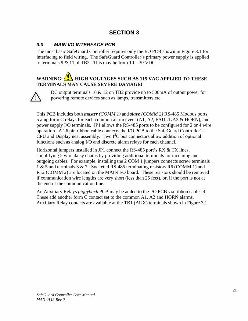
3.0 MAIN I/O INTERFACE PCB The most basic SafeGuard Controller requires only the I/O PCB shown in Figure 3.1 for interfacing to field wiring. The SafeGuard Controller’s primary power supply is applied to terminals 9 & 11 of TB2. This may be from 10 – 30 VDC.
WARNING: HIGH VOLTAGES SUCH AS 115 VAC APPLIED TO THESE TERMINALS MAY CAUSE SEVERE DAMAGE!
DC output terminals 10 & 12 on TB2 provide up to 500mA of output power for powering remote devices such as lamps, transmitters etc.
This PCB includes both master (COMM 1) and slave (COMM 2) RS-485 Modbus ports, 5 amp form C relays for each common alarm event (A1, A2, FAULT/A3 & HORN), and power supply I/O terminals. JP1 allows the RS-485 ports to be configured for 2 or 4 wire operation. A 26 pin ribbon cable connects the I/O PCB to the SafeGuard Controller’s CPU and Display nest assembly. Two I2C bus connectors allow addition of optional functions such as analog I/O and discrete alarm relays for each channel.
Horizontal jumpers installed in JP1 connect the RS-485 port’s RX & TX lines, simplifying 2 wire daisy chains by providing additional terminals for incoming and outgoing cables. For example, installing the 2 COM 1 jumpers connects screw terminals 1 & 5 and terminals 3 & 7. Socketed RS-485 terminating resistors R6 (COMM 1) and R12 (COMM 2) are located on the MAIN I/O board. These resistors should be removed if communication wire lengths are very short (less than 25 feet), or, if the port is not at the end of the communication line.
An Auxiliary Relays piggyback PCB may be added to the I/O PCB via ribbon cable J4. These add another form C contact set to the common A1, A2 and HORN alarms. Auxiliary Relay contacts are available at the TB1 (AUX) terminals shown in Figure 3.1.
22 SafeGuard Controller User Manual MAN-0115 Rev 0
Figure 3.1
Modbus Communication between SafeGuard and Digital Millennium II Series Transmitters. Examples: M2X-AD/ARD menu settings (See MAN-0076): Refer to MAN-0076 prior to attempting setup. Power up the unit and enter the transmitter Modbus menu option, (‘Modbus Setup’).
Select address 001 or the desired address for each unit.
Choose Baud Rate of 09600 bps.
Select ‘NO’ under parity. Note that the unit will retain its settings if power is removed.
M2B-D DIP Switch settings (See MAN-0082):
1. Refer to MAN-0082 prior to setup. Select the desired address for the device. Example: DIP Switch 1 positions 1, 2, 3, 4 “ON”. This corresponds to a Modbus Address of 1. Refer to MAN-0082.
2. Set DIP Switch 2 position 1 “OFF” and position 2 “ON”. This corresponds to a Baud Rate of 9600 bps.
3. Set DIP Switch 2 positions 3 and 4 in “OFF”. This allows 8 data bits, no parity bit, 2 stop bits (also compatible to 1 stop bit)
RS-485 terminating resistors (remove for short wire paths & when the SafeGuard Controller is not end of path)
TB2 terminals 10 & 12 provide Fused 24VDC power to the SafeGuard Controller option boards requiring such power
Aux. Relay piggy back Board shown in dotted lines

23 SafeGuard Controller User Manual MAN-0115 Rev 0
Connection between the Digital Millennium II Transmitter series and SafeGuard:
1. Prior to connection, ensure that the SafeGuard and the transmitter are not powered up.
2. Check to make sure the Millennium II Sensor is properly connected to the Millennium II Transmitter.
3. Connect the transmitter power terminals to the "DC Out" TB2 terminals (terminals 10 and 12) on the SafeGuard. Take note of the SafeGuard's positive and negative terminals at DC Out.
4. Connect the transmitter Modbus terminal "A" to the SafeGuard Master Comm 1 terminal 1 or Master Comm 1 terminal 5 on SafeGuard.
5. Connect the transmitter Modbus terminal "B” to the SafeGuard Master Comm 1 terminal 3 or Master Comm 1 terminal 7 on SafeGuard. Note that the SafeGuard's Master Comm1 terminals are the top terminals 1, 3, 5, 7. See Figure 3.1.
6. Jumper the transmitter’s ‘COM’ (-VDC) terminal and the Communication 'COM' terminal (tie them together).
7. Power up the SafeGuard. SafeGuard settings: Note: Leave Jumpers at JP1 in place for two wire RS-485 operation. See Figure 3.1.
1. Choose a Channel and select 'Data From', then choose the following settings:
• Modbus 16 Bit • Min raw: 00000 • Max raw: 00100 • Remote ID: 01 • Alias: 40001
2. Under “System”, select "Comm Ports" and choose the settings as follows:
• Slave ID: 01 • Slave Baud rate: 9600 • Parity: None • UART Timer: 155 s • Mastr TO 0200 ms • Mastr PR 0200 ms • ECHO ACK OFF
Proper communication between the two devices will be confirmed by the TX1 and RX1 LEDs. Note: When configuring other Net Safety products refer to specific user manual.
24 SafeGuard Controller User Manual MAN-0115 Rev 0
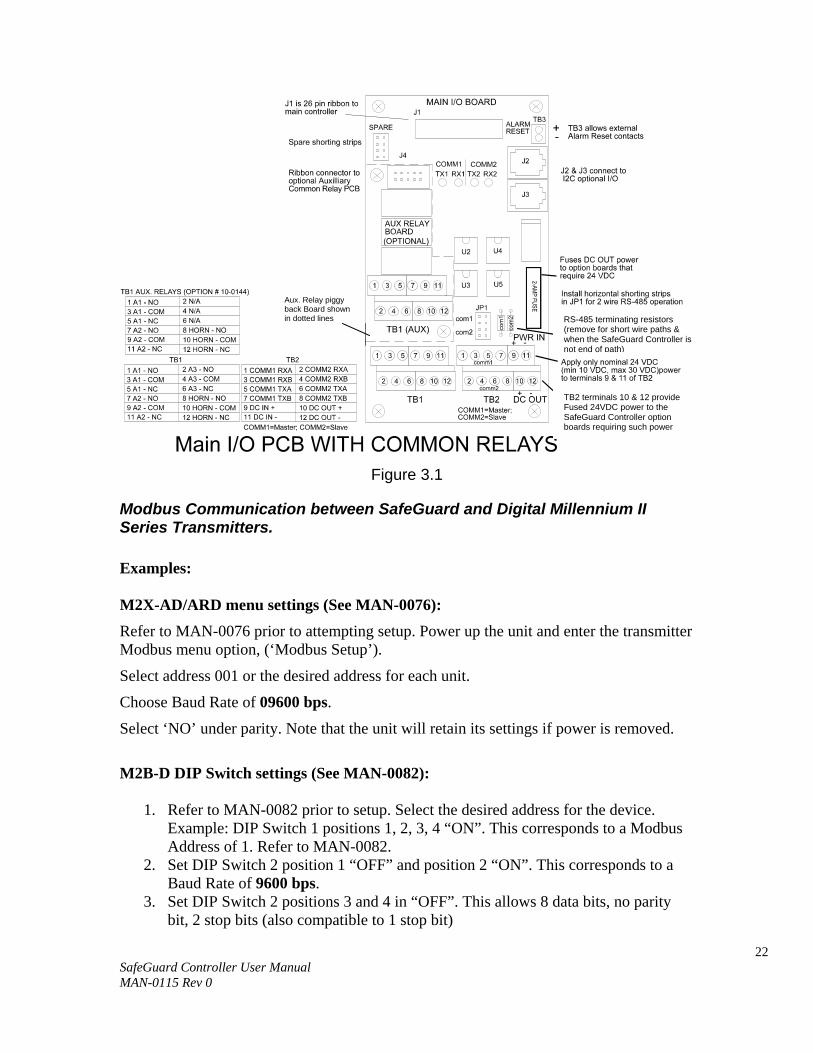
3.1 INPUT / OUTPUT OPTIONAL PCB’s Telephone style RJ11 connections are used to add optional 8 channel analog and digital I/O. A screen appears briefly after power up indicating what options are connected and for which channels. This information is also available from the Diagnostics Mode described in Section 4.
A N A L OG
P R E S S N E X T K E Y T O E X I T
I N P U T1- 8
F OU N D
A N A L OGI NP U T9 - 16
F OU N D
A N A L OGOU T P U T
1- 8F OU N D
A N A L OGOU T P UT
9 - 16F OUN D
A L A R M2R e l a y
1- 8F OUN D
A L A RM2I NP U T9 - 16
F OU N D
Figure 3.2
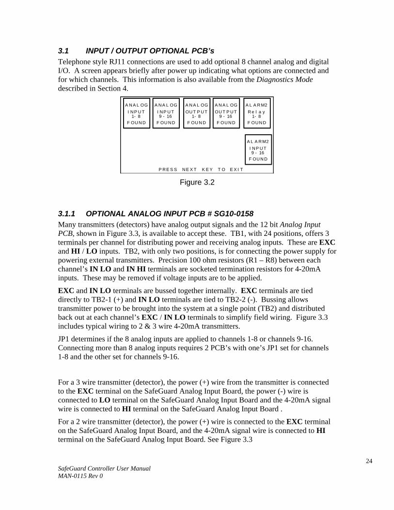
3.1.1 OPTIONAL ANALOG INPUT PCB # SG10-0158 Many transmitters (detectors) have analog output signals and the 12 bit Analog Input PCB, shown in Figure 3.3, is available to accept these. TB1, with 24 positions, offers 3 terminals per channel for distributing power and receiving analog inputs. These are EXC and HI / LO inputs. TB2, with only two positions, is for connecting the power supply for powering external transmitters. Precision 100 ohm resistors (R1 – R8) between each channel’s IN LO and IN HI terminals are socketed termination resistors for 4-20mA inputs. These may be removed if voltage inputs are to be applied.
EXC and IN LO terminals are bussed together internally. EXC terminals are tied directly to TB2-1 (+) and IN LO terminals are tied to TB2-2 (-). Bussing allows transmitter power to be brought into the system at a single point (TB2) and distributed back out at each channel’s EXC / IN LO terminals to simplify field wiring. Figure 3.3 includes typical wiring to 2 & 3 wire 4-20mA transmitters.
JP1 determines if the 8 analog inputs are applied to channels 1-8 or channels 9-16. Connecting more than 8 analog inputs requires 2 PCB’s with one’s JP1 set for channels 1-8 and the other set for channels 9-16.
For a 3 wire transmitter (detector), the power (+) wire from the transmitter is connected to the EXC terminal on the SafeGuard Analog Input Board, the power (-) wire is connected to LO terminal on the SafeGuard Analog Input Board and the 4-20mA signal wire is connected to HI terminal on the SafeGuard Analog Input Board .
For a 2 wire transmitter (detector), the power (+) wire is connected to the EXC terminal on the SafeGuard Analog Input Board, and the 4-20mA signal wire is connected to HI terminal on the SafeGuard Analog Input Board. See Figure 3.3
25 SafeGuard Controller User Manual MAN-0115 Rev 0
R2
R1
ANALOG INPUTS
R3
R4
R7
R6
R5
+EXC-
DC PWRTB2
R8
JP1
ST-71 ANALOG INPUT BOARD0010-1115 ASSY# 10-0158
J2
J1
J1 & J2 are interchangable I2Cconnectors used to add optionPCB assemblies to the ST-71.
JP1 determines if this 8 channelAnalog Input PCB provides inputsfor CH’s 1-8 or 9-16. 2 PCBassemblies are required for 16channels.
Socketed precision resistors R1-R8are 100 ohm terminations for 4-20mAinputs. 0-2 VDC voltage inputs maybe accepted by removing resistor.
TB2 is for powering bulk power to transmittersor other powered input devices. EXC+ iswired internally to channel “EXC’s” and EXC-to channel “LO’s”.CH1/9
EXC HICH7/15
HIEXCCH3/11
EXC LOHILOCH5/13
LOHI EXC LO
CH2/10HIEXC
CH8/16CH4/12EXC LOHILO EXC
CH6/14EXC LOHI LOHI
8 Channel Analog Input Option #10-0158
EXC LOHI
2 Wire 4-20mATransmitter
+Pwr Sig
3 Wire 4-20mATransmitter
EXC LOHI
+Pwr Sig Com Typical 2 & 3 wire 4-20mAtransmitter wiring (connectcorrect power, 24VDC orother, to TB2).
CH # (1-8) CH # (1-8)
Figure 3.3
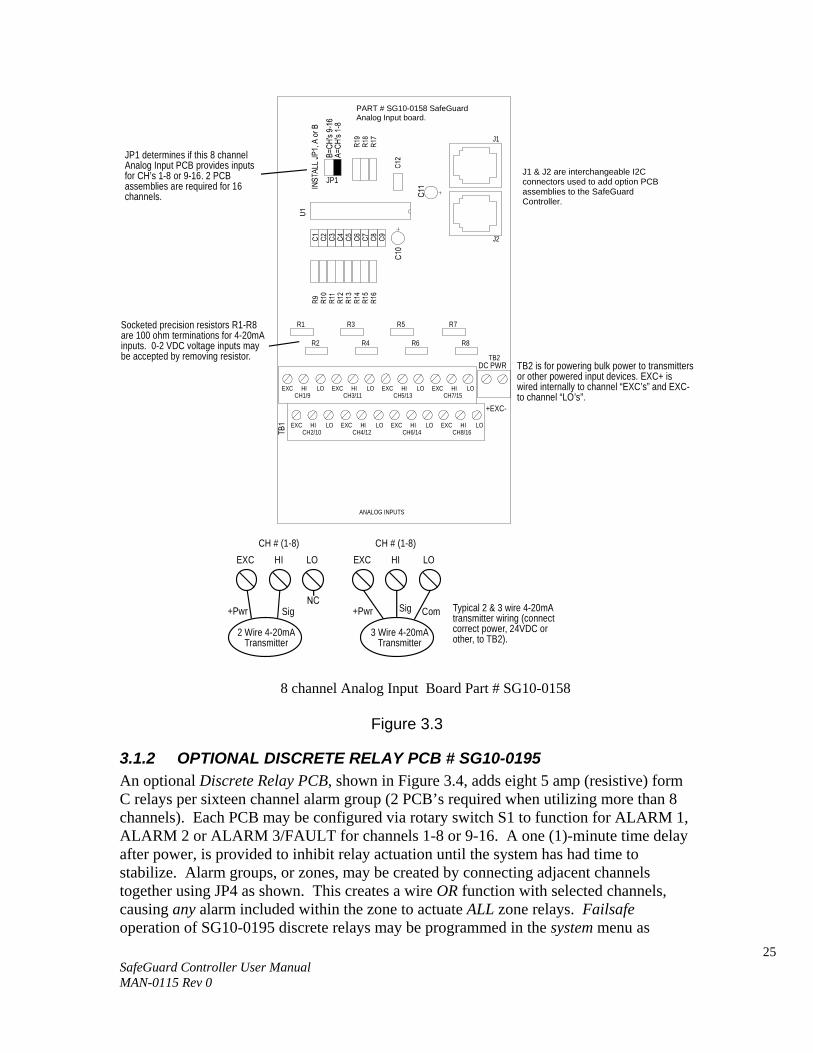
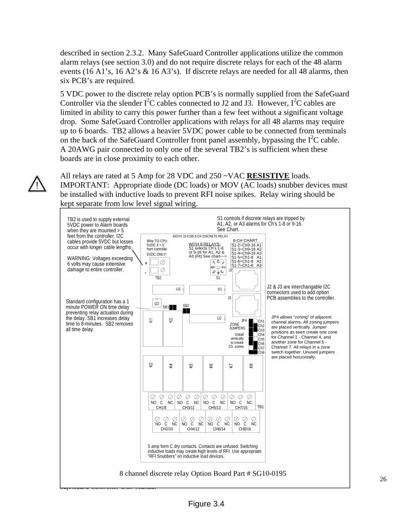
3.1.2 OPTIONAL DISCRETE RELAY PCB # SG10-0195 An optional Discrete Relay PCB, shown in Figure 3.4, adds eight 5 amp (resistive) form C relays per sixteen channel alarm group (2 PCB’s required when utilizing more than 8 channels). Each PCB may be configured via rotary switch S1 to function for ALARM 1, ALARM 2 or ALARM 3/FAULT for channels 1-8 or 9-16. A one (1)-minute time delay after power, is provided to inhibit relay actuation until the system has had time to stabilize. Alarm groups, or zones, may be created by connecting adjacent channels together using JP4 as shown. This creates a wire OR function with selected channels, causing any alarm included within the zone to actuate ALL zone relays. Failsafe operation of SG10-0195 discrete relays may be programmed in the system menu as
J1 & J2 are interchangeable I2C connectors used to add option PCB assemblies to the SafeGuard Controller.
PART # SG10-0158 SafeGuard Analog Input board.
8 channel Analog Input Board Part # SG10-0158
26 SafeGuard Controller User Manual MAN-0115 Rev 0
described in section 2.3.2. Many SafeGuard Controller applications utilize the common alarm relays (see section 3.0) and do not require discrete relays for each of the 48 alarm events (16 A1’s, 16 A2’s & 16 A3’s). If discrete relays are needed for all 48 alarms, then six PCB’s are required.
5 VDC power to the discrete relay option PCB’s is normally supplied from the SafeGuard Controller via the slender I2C cables connected to J2 and J3. However, I2C cables are limited in ability to carry this power further than a few feet without a significant voltage drop. Some SafeGuard Controller applications with relays for all 48 alarms may require up to 6 boards. TB2 allows a heavier 5VDC power cable to be connected from terminals on the back of the SafeGuard Controller front panel assembly, bypassing the I2C cable. A 20AWG pair connected to only one of the several TB2’s is sufficient when these boards are in close proximity to each other.
All relays are rated at 5 Amp for 28 VDC and 250 ~VAC RESISTIVE loads. IMPORTANT: Appropriate diode (DC loads) or MOV (AC loads) snubber devices must be installed with inductive loads to prevent RFI noise spikes. Relay wiring should be kept separate from low level signal wiring.
!
TB2
+-
5VDC ONLY!
ASSY# 10-0195 8-CH DISCRETE RELAY
TB1
JUMPERSZONE
JP4U2
J2
J3
Ch6Ch7
Ch5
Ch8
Ch3
Ch1Ch2
Ch4
S1 controls if discrete relays are tripped byA1, A2, or A3 alarms for Ch’s 1-8 or 9-16.See Chart.
JP4 allows “zoning” of adjacentchannel alarms. All zoning jumpersare placed vertically. Dwg. exhibitschannels 1-4 and channels 5-7creating 2 zones. All relays in a zoneswitch together. Unused jumpersmay be stored horizontally.
J2 & J3 are interchangable I2Cconnectors used to add optionPCB assemblies to the controller.
TB2 is used to supply external5VDC power to Alarm boardswhen they are mounted > 5feet from the controller. I2Ccables provide 5VDC but lossesoccur with longer cable lengths.
WARNING: Voltages exceeding6 volts may cause extensivedamage to entire controller.
CH1/9 CH3/11 CH7/15CH5/13NCNO C NO NCC NO NO CNCC NC
CH2/10 CH4/12 CH8/16CH6/14NCNO C NO NCC NO NO CNCC NC
5 amp form C dry contacts. Contacts are unfused. Switchinginductive loads may create high levels of RFI. Use appropriate“RFI Snubbers” on inductive load devices.
8 Channel Discrete Relay Option #10-0195
U1U3
Q2SB1 SB2
0
WITH 8 RELAYS:S1 selects Ch’s 1-8or 9-16 for A1, A2 &A3 (Flt) See chart--->
S1
S1-2=Ch9-16 A1S1-3=Ch9-16 A2S1-4=Ch9-16 A3S1-5=Ch1-8 A1S1-6=Ch1-8 A2S1-7=Ch1-8 A3
8-CH CHARTWire TO CPU5VDC if > 5’from controller
Installverticallyto create
Ch. zones
Standard configuration has a 1minute POWER ON time delaypreventing relay actuation duringthe delay. SB1 increases delaytime to 8-minutes. SB2 removesall time delay.
8 channel discrete relay Option Board Part # SG10-0195
Figure 3.4
JP4 allows “zoning” of adjacent channel alarms. All zoning jumpers are placed vertically. Jumper positions as seen create one zone for Channel 1 - Channel 4, and another zone for Channel 5 - Channel 7. All relays in a zone switch together. Unused jumpers are placed horizontally.
27 SafeGuard Controller User Manual MAN-0115 Rev 0
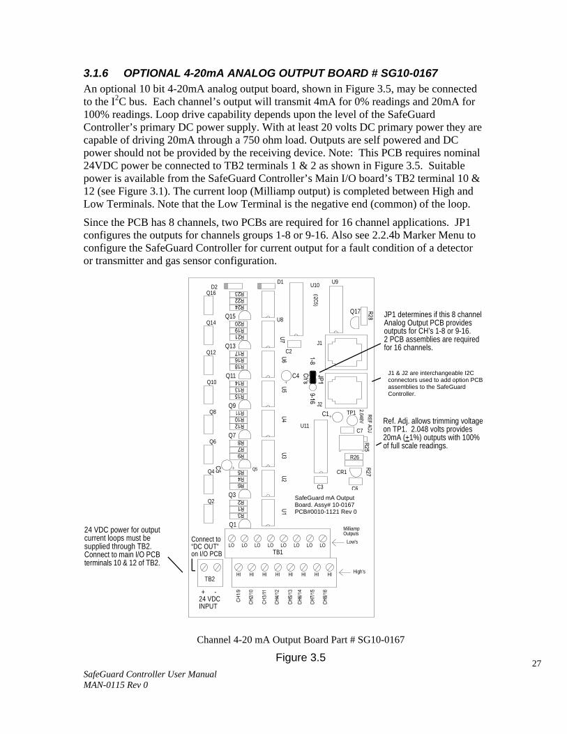
3.1.6 OPTIONAL 4-20mA ANALOG OUTPUT BOARD # SG10-0167 An optional 10 bit 4-20mA analog output board, shown in Figure 3.5, may be connected to the I2C bus. Each channel’s output will transmit 4mA for 0% readings and 20mA for 100% readings. Loop drive capability depends upon the level of the SafeGuard Controller’s primary DC power supply. With at least 20 volts DC primary power they are capable of driving 20mA through a 750 ohm load. Outputs are self powered and DC power should not be provided by the receiving device. Note: This PCB requires nominal 24VDC power be connected to TB2 terminals 1 & 2 as shown in Figure 3.5. Suitable power is available from the SafeGuard Controller’s Main I/O board’s TB2 terminal 10 & 12 (see Figure 3.1). The current loop (Milliamp output) is completed between High and Low Terminals. Note that the Low Terminal is the negative end (common) of the loop.
Since the PCB has 8 channels, two PCBs are required for 16 channel applications. JP1 configures the outputs for channels groups 1-8 or 9-16. Also see 2.2.4b Marker Menu to configure the SafeGuard Controller for current output for a fault condition of a detector or transmitter and gas sensor configuration.
TB1
Q4
Q6
Q2
Q10
Q12
Q8
D2Q16
Q14
HIHI HIHI HI HI HIHI
U11
ST-71 mA OUTPUT BOARD
Q1
LO LO LOLO LO LOLO LO
Q5
Q3
Q7
PCB # 0010-1121Assy # 10-0167
C3
High's
Milliamp
Low'sOutputs
Rev 0
CR1
C6
R26
C7
U9
Q13
Q11
Q9
C4
C1J2
C2J1
D1
U8Q15
U10
TP1
Q17
J1 & J2 are interchangable I2Cconnectors used to add optionPCB assemblies to the ST-71.
8 Channel 4-20mA Output Option #10-0167
JP1 determines if this 8 channelAnalog Output PCB providesoutputs for CH’s 1-8 or 9-16.2 PCB assemblies are requiredfor 16 channels.
Ref. Adj. allows trimming voltageon TP1. 2.048 volts provides20mA (+1%) outputs with 100%of full scale readings.
-+
Connect to“DC OUT”on I/O PCB
24 VDCINPUT
24 VDC power for outputcurrent loops must besupplied through TB2.Connect to main I/O PCBterminals 10 & 12 of TB2.
TB2
J1 & J2 are interchangeable I2C connectors used to add option PCB assemblies to the SafeGuard Controller.
SafeGuard mA Output Board. Assy# 10-0167 PCB#0010-1121 Rev 0
Channel 4-20 mA Output Board Part # SG10-0167
Figure 3.5

28 SafeGuard Controller User Manual MAN-0115 Rev 0
3.1.8 OPTIONAL 24VDC 150 WATT POWER SUPPLY The SafeGuard Controller may be powered from 10-30VDC. However, many applications require 24VDC power for the monitors or transmitters providing inputs to the SafeGuard Controller. A 150 watt AC / DC power supply may be included for these applications (115VAC or 230 VAC selected via slide switch). When ordered from the factory, it is pre-wired to provide 24VDC primary power for the SafeGuard Controller as well as any transmitters or monitors that may be connected by the end user.
Figure 3.6
150 Watt 24 VDC Power Supply Option # SG10-0172
29 SafeGuard Controller User Manual MAN-0115 Rev 0
!
SECTION 4
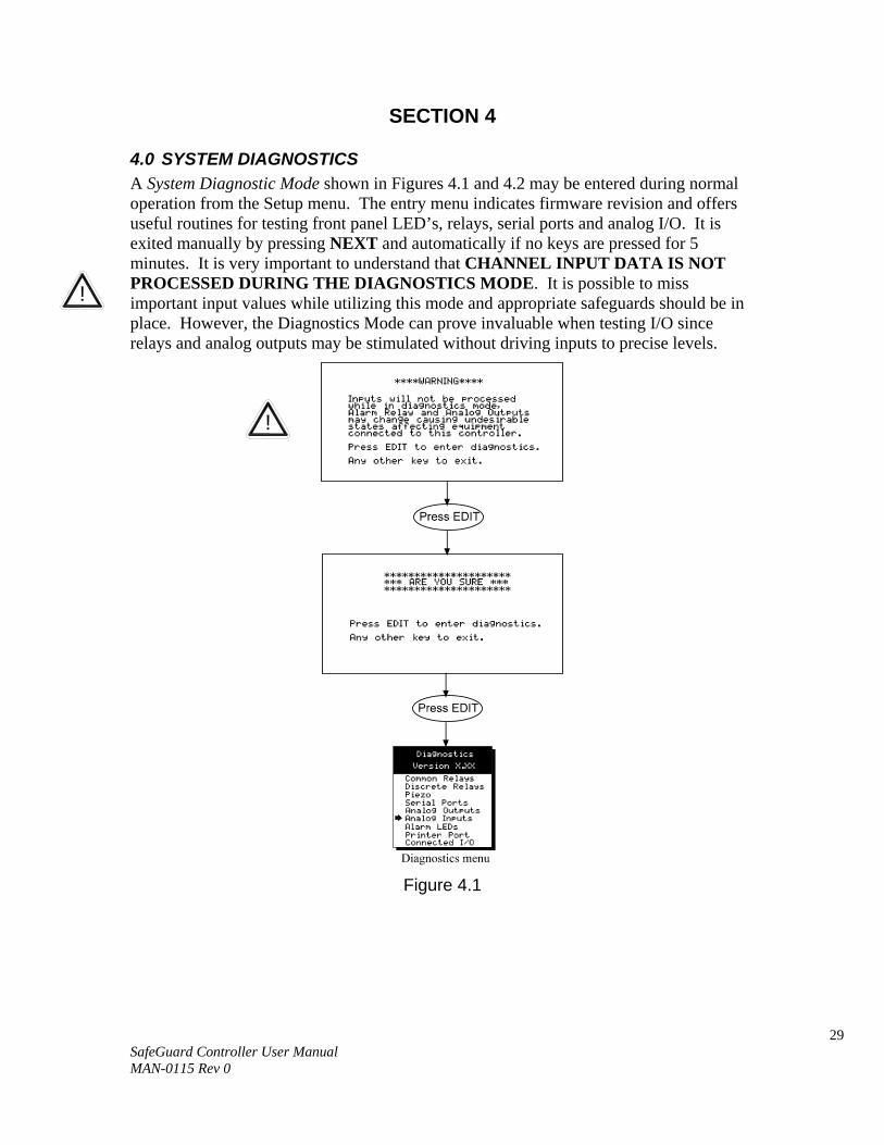
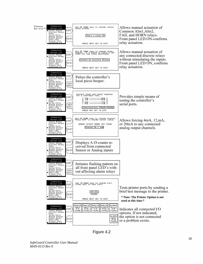
4.0 SYSTEM DIAGNOSTICS A System Diagnostic Mode shown in Figures 4.1 and 4.2 may be entered during normal operation from the Setup menu. The entry menu indicates firmware revision and offers useful routines for testing front panel LED’s, relays, serial ports and analog I/O. It is exited manually by pressing NEXT and automatically if no keys are pressed for 5 minutes. It is very important to understand that CHANNEL INPUT DATA IS NOT PROCESSED DURING THE DIAGNOSTICS MODE. It is possible to miss important input values while utilizing this mode and appropriate safeguards should be in place. However, the Diagnostics Mode can prove invaluable when testing I/O since relays and analog outputs may be stimulated without driving inputs to precise levels.
Figure 4.1
!
30 SafeGuard Controller User Manual MAN-0115 Rev 0
Figure 4.2
* Note: The Printer Option is not used at this time.*
31 SafeGuard Controller User Manual MAN-0115 Rev 0
SECTION 5
5.0 MODBUS RS-485 PORTS The SafeGuard Controller is equipped with Master (COMM 1), and Slave (COMM 2), modbus RTU ports. Port configurations are described in sections 2.2 and 2.3 of this manual. Section 5.0 defines register locations of data available via the SafeGuard Controller’s slave port.
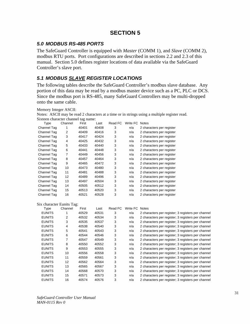
5.1 MODBUS SLAVE REGISTER LOCATIONS The following tables describe the SafeGuard Controller’s modbus slave database. Any portion of this data may be read by a modbus master device such as a PC, PLC or DCS. Since the modbus port is RS-485, many SafeGuard Controllers may be multi-dropped onto the same cable. Memory Integer ASCII: Notes: ASCII may be read 2 characters at a time or in strings using a multiple register read. Sixteen character channel tag name:
Type Channel First Last Read FC Write FC Notes Channel Tag 1 40401 40408 3 n/a 2 characters per register Channel Tag 2 40409 40416 3 n/a 2 characters per register Channel Tag 3 40417 40424 3 n/a 2 characters per register Channel Tag 4 40425 40432 3 n/a 2 characters per register Channel Tag 5 40433 40440 3 n/a 2 characters per register Channel Tag 6 40441 40448 3 n/a 2 characters per register Channel Tag 7 40449 40456 3 n/a 2 characters per register Channel Tag 8 40457 40464 3 n/a 2 characters per register Channel Tag 9 40465 40472 3 n/a 2 characters per register Channel Tag 10 40473 40480 3 n/a 2 characters per register Channel Tag 11 40481 40488 3 n/a 2 characters per register Channel Tag 12 40489 40496 3 n/a 2 characters per register Channel Tag 13 40497 40504 3 n/a 2 characters per register Channel Tag 14 40505 40512 3 n/a 2 characters per register Channel Tag 15 40513 40520 3 n/a 2 characters per register Channel Tag 16 40521 40528 3 n/a 2 characters per register
Six character Eunits Tag:
Type Channel First Last Read FC Write FC Notes EUNITS 1 40529 40531 3 n/a 2 characters per register; 3 registers per channel EUNITS 2 40532 40534 3 n/a 2 characters per register; 3 registers per channel EUNITS 3 40535 40537 3 n/a 2 characters per register; 3 registers per channel EUNITS 4 40538 40540 3 n/a 2 characters per register; 3 registers per channel EUNITS 5 40541 40543 3 n/a 2 characters per register; 3 registers per channel EUNITS 6 40544 40546 3 n/a 2 characters per register; 3 registers per channel EUNITS 7 40547 40549 3 n/a 2 characters per register; 3 registers per channel EUNITS 8 40550 40552 3 n/a 2 characters per register; 3 registers per channel EUNITS 9 40553 40555 3 n/a 2 characters per register; 3 registers per channel EUNITS 10 40556 40558 3 n/a 2 characters per register; 3 registers per channel EUNITS 11 40559 40561 3 n/a 2 characters per register; 3 registers per channel EUNITS 12 40562 40564 3 n/a 2 characters per register; 3 registers per channel EUNITS 13 40565 40567 3 n/a 2 characters per register; 3 registers per channel EUNITS 14 40568 40570 3 n/a 2 characters per register; 3 registers per channel EUNITS 15 40571 40573 3 n/a 2 characters per register; 3 registers per channel EUNITS 16 40574 40576 3 n/a 2 characters per register; 3 registers per channel

32 SafeGuard Controller User Manual MAN-0115 Rev 0
Six character Value ASCII string: Type Channel First Last Read FC Write FC Notes
ASCII Value 1 40577 40579 3 n/a 2 characters per register; 3 registers per channel ASCII Value 2 40580 40582 3 n/a 2 characters per register; 3 registers per channel ASCII Value 3 40583 40585 3 n/a 2 characters per register; 3 registers per channel ASCII Value 4 40586 40588 3 n/a 2 characters per register; 3 registers per channel ASCII Value 5 40589 40591 3 n/a 2 characters per register; 3 registers per channel ASCII Value 6 40592 40594 3 n/a 2 characters per register; 3 registers per channel ASCII Value 7 40595 40597 3 n/a 2 characters per register; 3 registers per channel ASCII Value 8 40598 40600 3 n/a 2 characters per register; 3 registers per channel ASCII Value 9 40601 40603 3 n/a 2 characters per register; 3 registers per channel ASCII Value 10 40604 40606 3 n/a 2 characters per register; 3 registers per channel ASCII Value 11 40607 40609 3 n/a 2 characters per register; 3 registers per channel ASCII Value 12 40610 40612 3 n/a 2 characters per register; 3 registers per channel ASCII Value 13 40613 40615 3 n/a 2 characters per register; 3 registers per channel ASCII Value 14 40616 40618 3 n/a 2 characters per register; 3 registers per channel ASCII Value 15 40619 40621 3 n/a 2 characters per register; 3 registers per channel ASCII Value 16 40622 40624 3 n/a 2 characters per register; 3 registers per channel
Memory Floating Point: Notes: Returned as 15 bit 2s complement with +- 5% over/under range applied.. Therefore, this must be considered when scaling values to be displayed at the modbus master. The following equation may be used to determine a value for display. Display Value = MODBUS Value [ (Span Value -Zero Value) 1.1] + {Zero Value - [(Span Value - Zero Value) .05]}
32767
Type Channel First Last Read FC Write FC Notes Channel Value 1-16 33001-16 n/a 4 n/a 15bit 2s complement w/+- 5% over/under range Analog Output: Notes: 12 bit integer for Channel Reading value = 800 counts = zero value, 4000 counts = 100% value.
Type Channel First Last Read FC Write FC Notes Channel Reading
1-16 31001 31016 4 n/a 12bit integer

33 SafeGuard Controller User Manual MAN-0115 Rev 0
Channel Status words contain configuration and status bits for a channel. They are as follows: Type Channel First Last Read FC Write FC Notes
Channel Status 1-16 31017 31032 4 n/a 16bit integer (see bit by bit definition below) Alarm 1 Trip bit0 1 = Low 0 = High Alarm 1 Horn Drive bit1 1 = On 0 = Off Alarm 3 Type bit2 1 = Level 0 = Fault Alarm 2 Horn Drive bit3 1 = On 0 = Off Linearize bit4 1 = On 0 = Off Alarm 3 Trip bit5 1 = Low 0 = High Input Marker bit6 1 = Input Marker Detected 0 = Normal Mode Channel Disable bit7 1 = Disabled 0 = Enabled Controller Channel In Cal bit8 1 = Local Cal Mode 0 = Normal Mode Modbus Data Type bit9 1 = 4 byte float 0 = 2 byte integer reserved bit10 reserved reserved reserved bit11 reserved reserved Alarm 1 Latch bit12 1 = Latching 0 = Non latching Alarm 2 Latch bit13 1 = Latching 0 = Non latching Alarm 3 Latch bit14 1 = Latching 0 = Non latching Alarm 2 Trip bit15 1 = Low 0 = High
Alarm status words are bits packed into 16 bit integer where lsb = channel 1 alarm status and msb = channel 16 alarm status. Alarm status (bit = 1 indicates alarm is active):
Type Channel First Last Read FC Write FC Notes Alarm 1 Status 1-16 31033 n/a 4 n/a packed 16bit integer Alarm 2 Status 1-16 31034 n/a 4 n/a packed 16bit integer Alarm 3 Status 1-16 31035 n/a 4 n/a packed 16bit integer *Relay Status n/a 31036 n/a 4 n/a packed 16bit integer
*Note: Common Relay status bits (register 31036) are as follows. Relay 1= bit0. Relay 2= bit1 Fault Relay = bit2 Horn Relay = bit3
Type Channel First Last Read FC Write FC Notes Cal Status 1-16 31037 n/a 4 n/a packed 16bit integer
Trend Interval Timer
1-16 31038 n/a 4 n/a 16bit integer (Time in Seconds)
Fault Status 1-16 31039 n/a 4 n/a packed 16bit integer
Alarm LED flashing status (bit = 1 indicates LED is flashing; “Acknowledge” clears all to 0): Type Channel First Last Read FC Write FC Notes
Alarm 1 Status 1-16 31049 n/a 4 n/a packed 16bit integer Alarm 2 Status 1-16 31050 n/a 4 n/a packed 16bit integer Alarm 3 Status 1-16 31051 n/a 4 n/a packed 16bit integer Common LED
Status 1-16 31052 n/a 4 n/a packed 16bit integer
LCD Display Screen Displayed Integer: Type Channel First Last Read FC Write FC Notes
LCD Screen n/a 31053 n/a 4 n/a 8bit integer
Sensor Life (not used at this time) Type Channel First Last Read FC Write FC Notes
Sensor Life 1 31065 n/a 4 n/a Signed 16bit integer Sensor Life 2 31066 n/a 4 n/a Signed 16bit integer Sensor Life 3 31067 n/a 4 n/a Signed 16bit integer Sensor Life 4 31068 n/a 4 n/a Signed 16bit integer

34 SafeGuard Controller User Manual MAN-0115 Rev 0
Sensor Life 5 31069 n/a 4 n/a Signed 16bit integer Sensor Life 6 31070 n/a 4 n/a Signed 16bit integer Sensor Life 7 31071 n/a 4 n/a Signed 16bit integer Sensor Life 8 31072 n/a 4 n/a Signed 16bit integer Sensor Life 9 31073 n/a 4 n/a Signed 16bit integer Sensor Life 10 31074 n/a 4 n/a Signed 16bit integer Sensor Life 11 31075 n/a 4 n/a Signed 16bit integer Sensor Life 12 31076 n/a 4 n/a Signed 16bit integer Sensor Life 13 31077 n/a 4 n/a Signed 16bit integer Sensor Life 14 31078 n/a 4 n/a Signed 16bit integer Sensor Life 15 31079 n/a 4 n/a Signed 16bit integer Sensor Life 16 31080 n/a 4 n/a Signed 16bit integer
*Note: -2 = Disabled, -1 = CAL Required, 0-100 = Sensor Life
Coils Notes: Set this coil to issue an alarm “Acknowledge” via modbus.
Type Channel First Last Read FC Write FC Notes Alarm Reset n/a 2001 n/a n/a 5 write 0xff to high byte to set
Memory Discretes Notes: May be read as single discrete or packed with multiple register read.
Type Channel First Last Read FC Write FC Notes Chnl Alarm 1 1-16 12001-16 n/a 2 n/a discrete, may be packed
Type Channel First Last Read FC Write FC Notes
Chnl Alarm 2 1-16 12017-32 n/a 2 n/a discrete, may be packed
Type Channel First Last Read FC Write FC Notes Chnl Alarm 3 1-16 12033-48 n/a 2 n/a discrete, may be packed
Memory Reals Notes: Real value represents float value without the decimal point such as 123.4 is returned as 1234. Decimal devisor is returned as 1, 10, 100, or 1000 for decimal position of 1, 2, 3, or 4, where 123.4 would return the value 10.
Type Channel First Last Read FC Write FC Notes Zero Real 1-16 41001-16 n/a 3 n/a zero real w/o decimal point Zero DP 1-16 41017-32 n/a 3 n/a zero real divisor
Span Real 1-16 41033-48 n/a 3 n/a span real w/o decimal point Span DP 1-16 41049-64 n/a 3 n/a span real divisor
Alarm 1 Real 1-16 41065-80 n/a 3 n/a alarm 1 real w/o decimal point Alarm 1 DP 1-16 41081-96 n/a 3 n/a alarm 1 real divisor
Alarm 2 Real 1-16 41097-112 n/a 3 n/a alarm 2 real w/o decimal point Alarm 2 DP 1-16 41113-28 n/a 3 n/a alarm 2 real divisor
Alarm 3 Real 1-16 41129-44 n/a 3 n/a alarm 3 real w/o decimal point Alarm 3 DP 1-16 41145-60 n/a 3 n/a alarm 3 real divisor Fault Real 1-16 41161-76 n/a 3 n/a alarm 3 real w/o decimal point Fault DP 1-16 41177-92 n/a 3 n/a alarm 3 real divisor
35 SafeGuard Controller User Manual MAN-0115 Rev 0
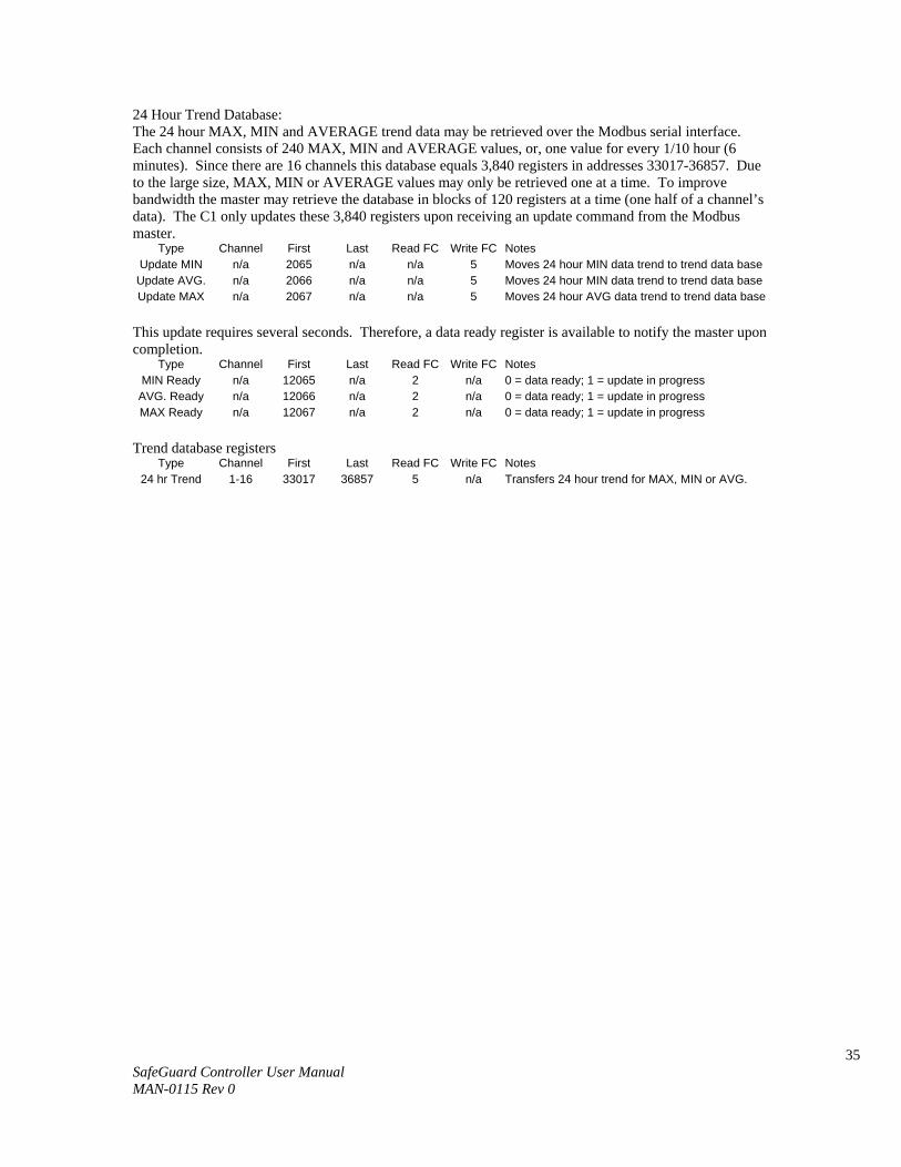
24 Hour Trend Database: The 24 hour MAX, MIN and AVERAGE trend data may be retrieved over the Modbus serial interface. Each channel consists of 240 MAX, MIN and AVERAGE values, or, one value for every 1/10 hour (6 minutes). Since there are 16 channels this database equals 3,840 registers in addresses 33017-36857. Due to the large size, MAX, MIN or AVERAGE values may only be retrieved one at a time. To improve bandwidth the master may retrieve the database in blocks of 120 registers at a time (one half of a channel’s data). The C1 only updates these 3,840 registers upon receiving an update command from the Modbus master.
Type Channel First Last Read FC Write FC Notes Update MIN n/a 2065 n/a n/a 5 Moves 24 hour MIN data trend to trend data base
Update AVG. n/a 2066 n/a n/a 5 Moves 24 hour MIN data trend to trend data base Update MAX n/a 2067 n/a n/a 5 Moves 24 hour AVG data trend to trend data base
This update requires several seconds. Therefore, a data ready register is available to notify the master upon completion.
Type Channel First Last Read FC Write FC Notes MIN Ready n/a 12065 n/a 2 n/a 0 = data ready; 1 = update in progress
AVG. Ready n/a 12066 n/a 2 n/a 0 = data ready; 1 = update in progress MAX Ready n/a 12067 n/a 2 n/a 0 = data ready; 1 = update in progress
Trend database registers Type Channel First Last Read FC Write FC Notes
24 hr Trend 1-16 33017 36857 5 n/a Transfers 24 hour trend for MAX, MIN or AVG.
36 SafeGuard Controller User Manual MAN-0115 Rev 0
SECTION 6
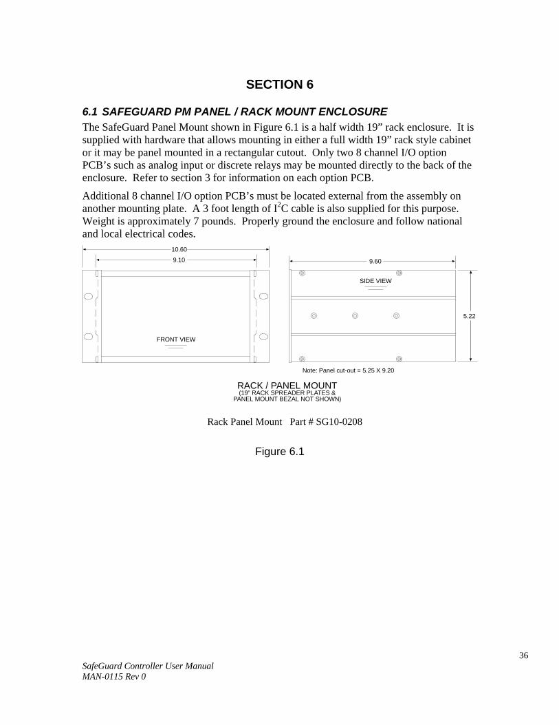
6.1 SAFEGUARD PM PANEL / RACK MOUNT ENCLOSURE The SafeGuard Panel Mount shown in Figure 6.1 is a half width 19” rack enclosure. It is supplied with hardware that allows mounting in either a full width 19” rack style cabinet or it may be panel mounted in a rectangular cutout. Only two 8 channel I/O option PCB’s such as analog input or discrete relays may be mounted directly to the back of the enclosure. Refer to section 3 for information on each option PCB.
Additional 8 channel I/O option PCB’s must be located external from the assembly on another mounting plate. A 3 foot length of I2C cable is also supplied for this purpose. Weight is approximately 7 pounds. Properly ground the enclosure and follow national and local electrical codes.
RACK / PANEL MOUNT(19” RACK SPREADER PLATES &
PANEL MOUNT BEZAL NOT SHOWN)
10.60
9.10
FRONT VIEW
5.22
SIDE VIEW
9.60
Note: Panel cut-out = 5.25 X 9.20
Figure 6.1
Rack Panel Mount Part # SG10-0208

37 SafeGuard Controller User Manual MAN-0115 Rev 0
6.2 SAFEGUARD N4 NEMA 4X WALL MOUNT FIBERGLASS ENCLOSURE The SafeGuard N4 shown in Figure 6.2 is a fiberglass NEMA 4X wall mount enclosure. Seven, 8 channel I/O option PCB’s, such as analog input or discrete relays, may be mounted inside this enclosure. Refer to section 3 for information on each option PCB.
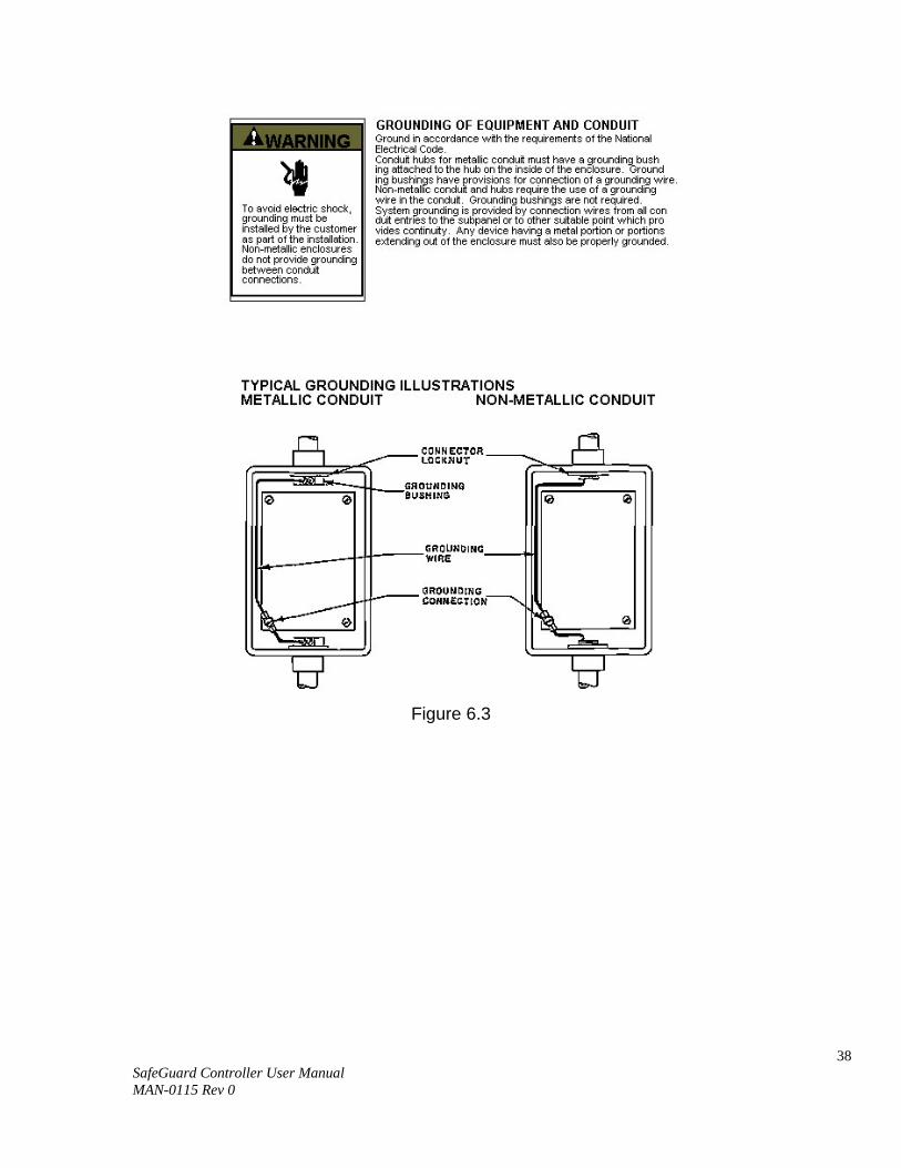
The enclosure may be mounted outdoors with a weather deflector shield. It weighs approximately 17 pounds. Figure 6.3 provides important warning information concerning correct grounding procedures for non-metallic enclosures. Conduit entries are not provided so installers may place entries as needed. Bottom or lower side areas are recommended. Care must be taken to avoid drilling into circuit boards mounted inside the enclosure. Properly ground the enclosure and follow national and local electrical codes.
Figure 6.2
38 SafeGuard Controller User Manual MAN-0115 Rev 0
Figure 6.3
39 SafeGuard Controller User Manual MAN-0115 Rev 0
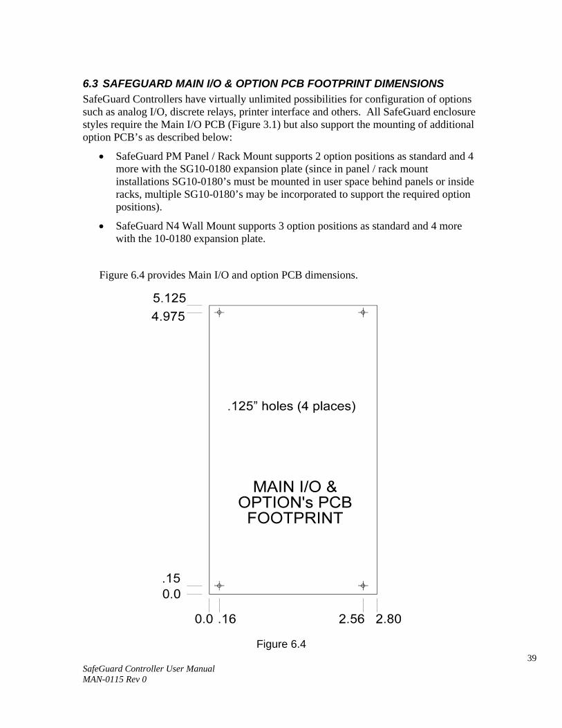
6.3 SAFEGUARD MAIN I/O & OPTION PCB FOOTPRINT DIMENSIONS SafeGuard Controllers have virtually unlimited possibilities for configuration of options such as analog I/O, discrete relays, printer interface and others. All SafeGuard enclosure styles require the Main I/O PCB (Figure 3.1) but also support the mounting of additional option PCB’s as described below:
• SafeGuard PM Panel / Rack Mount supports 2 option positions as standard and 4 more with the SG10-0180 expansion plate (since in panel / rack mount installations SG10-0180’s must be mounted in user space behind panels or inside racks, multiple SG10-0180’s may be incorporated to support the required option positions).
• SafeGuard N4 Wall Mount supports 3 option positions as standard and 4 more with the 10-0180 expansion plate.
Figure 6.4 provides Main I/O and option PCB dimensions.
Figure 6.6
Figure 6.4

40 SafeGuard Controller User Manual MAN-0115 Rev 0
SECTION 7 – HOW TO RETURN EQUIPMENT
A Material Return Authorization number is required in order to return equipment. Please contact Net Safety Monitoring at (403) 219-0688, before returning equipment or consult our Service Department to possibly avoid returning equipment.
If you are required to return equipment, include the following information:
1. A Material Return Authorization number (provided over the phone to you by Net
Safety). 2. A detailed description of the problem. The more specific you are regarding the
problem, the quicker our Service Department can determine and correct the problem.
3. A company name, contact name and telephone number. 4. A purchase order, from your company, authorizing repairs or request for quote. 5. Ship all equipment, prepaid to: Net Safety Monitoring Inc.,
2721 Hopewell Place NE, Calgary, Alberta Canada, T1Y 7J7
6. Mark all packages: RETURN for REPAIR. 7. Waybills, for shipment outside Canada, must state: Equipment being returned
for repair All charges to be billed to the sender
Ensure a duplicate copy of the packing slip is enclosed inside the box indicating item 1 – 4 along with the courier and account number for returning the goods. Pack items to protect them from damage and use anti-static bags or aluminum-backed cardboard as protection from electro-static discharge.
ALL equipment must be shipped prepaid. Collect shipments will not be accepted.

41 SafeGuard Controller User Manual MAN-0115 Rev 0
Appendix
Appendix A: Electrostatic Sensitive Device (ESD) Definition: Electrostatic discharge (ESD) is the transfer, between bodies, of an electrostatic charge caused by direct contact or induced by an electrostatic field. The most common cause of ESD is physical contact. Touching an object can cause a discharge of electrostatic energy—ESD! If the charge is sufficient and occurs near electronic components, it can damage or destroy those components. In some cases, damage is instantaneous and an immediate malfunction occurs. However, symptoms are not always immediate—performance may be marginal or seemingly normal for an indefinite period of time, followed by a sudden failure. To eliminate potential ESD damage, review the following guidelines: • Handle boards by metal shields—taking care not to touch electronic components. • Wear grounded wrist or foot straps, ESD shoes or heel grounders to dissipate
unwanted static energy. • Prior to handling boards, dispel any charge in your body or equipment. • Ensure all components are transported and stored in static safe packaging • When returning boards, carefully package in the original carton and static protective
wrapping • Ensure ALL personnel are educated and trained in ESD Control Procedures
In general, exercise accepted and proven precautions normally observed when handling electrostatic sensitive devices. A warning label is placed on the packaging, identifying product using electrostatic sensitive semiconductor devices.

42 SafeGuard Controller User Manual MAN-0115 Rev 0
Net Safety Monitoring Inc. 2721 Hopewell Place NE, Calgary, AB Canada T1Y 7J7 1‐866‐FIREGAS (347‐3427) | ph. (403) 219‐0688 | fx. (403) 219‐0694 http://www.net‐safety.com | Email: nsmsales@net‐safety.com
PRODUCT SERVICES CONTACT INFORMATION Telephone [ 8am ‐ 5pm MDT ]: (403) 769‐6074 | (403) 717‐8219 Fax: (403) 219‐0694 Email: productservices@net‐safety.com http://www.net‐safety.com/service/product_services.html


![[FGD I3M] Fgd pimnas + solusi](https://img.pdfslide.us/doc/110x75/558a2bccd8b42aca328b459a/fgd-i3m-fgd-pimnas-solusi.jpg)