Embed Size (px)
Citation preview

SUBCHAPTERI PURPOSE, SCOPE, APPLICATION AND
COMPLIANCE Comm 65.0001 Purpose and scope.
(1) Purpose. The purpose of this chapter is to regulate the design, installation, operation and maintenance of gas-fueled heating, ventilating and air-conditioning systems in buildings and structures as specified in ch. Comm 61.
(2) Scope. The scope of this chapter is as specified in s. Comm 61.02.
Comm 65.0002 Application.
(1) General. The application of this chapter is as specified in s. Comm 61.03 and as modified in this section.
(2) Applicability. All heating, ventilating and air-conditioning systems shall be designed, installed, maintained and operated so as to provide the service and results required within the provisions of this chapter. The minimum requirements established in each part of this chapter shall be complied with as they apply to the structures and facilities covered in the IBC.
(3) Additions.
(a) This chapter applies to all additions to existing buildings and structures as specified in s. Comm 61.03.
(b) Except when an existing heating, ventilation and air-conditioning system is extended to serve an addition, existing system components are not required to be replaced if the provisions in this chapter are met within the addition.
(4) Alterations.
(a) This chapter applies to all remodeling and alterations in any building or structure which affect the replacement of major equipment as specified in s. Comm 61.03.
(b) When an existing heating, ventilating and air conditioning system serves a remodeled or altered space that has not undergone a change in occupancy or use, the existing system con1ponents are not required to be replaced if the provisions in this chapter that applied to the original construction of the space are met.
Note: "Occupancy or use" refers to the entries in Table 64.0403.
Note: Maintenance and repair to existing equipment when there is no change to the building or occupancy, is considered an alteration.
2002 WISCONSIN ENROLLED COMMERCIAL BUILDING CODE
Comm 65.0003 Compliance. All gas-fueled heating, ventilating and air-conditioning syste1ns in buildings and structures shall comply with the IFGC and the changes, additions or omissions under subch. IL
Comm 65.0004 Approval of drawings and specifications. All drawings and specifications shall be submitted to the department in accordance with the provisions of subch. III, ch. Comm 61.
SUBCHAPTER II CHANGES, ADDITIONS OR OMISSIONS TO THE
INTERNATIONAL FUEL GAS CODE (IFGC) Comm 65.0100 Changes, Additions or Omissions to the Jn. ternational Fuel Gas Code (IFGC). Changes, additions or otnissions to the International Fuel Gas Code are specified in this subchapter and are rules of the department and are not requirements of the IFGC. Note: This subchapter is numbered to correspond with the numbering used within the model code; i.e., s. Conun 65.0201 refers to section IFGC 201.
FG-1

FG·2 2002 WISCONSIN ENROLLED COMMERCIAL BUILDING CODE

SECTION 101 GENERAL
Deleted
SECTION 102 (IFGC) APPLICABILITY
102.1 - 102.7 Deleted.
CHAPTER 1
ADMINISTRATION
102.8 Referenced codes and standards. The codes and standards referenced in this code shall be those that are listed in Chapter 7 and such codes and standards shall be considered part of the requirements of this code to the prescribed extent of each such reference. Where differences occur between provisions of this code and the referenced standards, the provisions of this code shall apply.
Exception: Where enforcement of a code provision would violate the conditions of the listing of the equipment or appliance, the conditions of the listing and the manufacturer's installation instructions shall apply.
102.9 Deleted.
SECTIONS 103 -107 Deleted
SECTION 108 (IFGC) VIOLATIONS
108.1 - 108.6 Deleted.
108.7 Unsafe installations. An installation that is unsafe, constitutes a fire or health hazard1 or is othe1wise dangerous to human life, as regulated by this code, is hereby declared as an unsafe installation. Use of an installation regulated by this code constituting a hazard to health, safety or welfare by reason of inadequate maintenance, dilapidation, fire hazard, disaster, damage or abandonment is hereby declared an unsafe use. Such unsafe installations are hereby declared to be a public nuisance and shall be abated by repair, rehabilitation, demolition or removal.
108.7.1 - 108.7.3 Deleted.
SECTION 109 MEANS OF APPEAL
Deleted
2002 WISCONSIN ENROLLED COMMERCIAL BUILDING CODE FG-3

FG-4 2002 WISCONSIN ENROLLED COMMERCIAL BUILDING CODE

CHAPTER 2
DEFINITIONS
SECTION 201 (IFGC) GENERAL
201.1 Scope. Unless otherwise expressly stated, the following words and terms shall, for the purposes of this code and standard, have the meanings indicated in this chapter.
201.2 Interchangeability. Words used in the present tense include the future; words in the masculine gender include the feminine and neuter; the singular number includes the plural and the plural, the singular.
201.3 Terms defined in other codes. Where te1ms are not defined in this code and are defined in the ICC Electrical Code, International Building Code, International Fire Code, Inte111ationalMechanical Code, or International P!tanbing Code, such terms shall have meanings ascribed to them as in those codes.
201.4 Terms not defined. Where terms are not defined through the methods authotized by this section, such terms shall have ordinaiily accepted meanings such as the context implies.
SECTION 202 (IFGC) GENERAL DEFINITIONS
ACCESS (TO). That which enables a device, appliance or equipment to be reached by ready access or by a means that first requires the removal or movement of a panel, door or similar obstmction (see also "Ready access").
AIR CONDITIONER, GAS-FIRED. A gas-burning, automatically operated appliance for supplying cooled and/or dehumidified air or chilled liquid.
AIR CONDITIONING. The treatment of air so as to control sitnultaneously the temperature, hu1nidity, cleanness and distribution of the air to meet the requirements of a conditioned space.
AIR, EXHAUST. Air being removed from any space or piece of equipment and conveyed directly to the atmosphere by means of openings or ducts.
AIR-HANDLING UNIT. A blower or fan used for the purpose of disttibuting supply air to a room, space or area.
AIR, MAKEUP. Air that is provided to replace air being exhausted.
2002 WISCONSIN ENROLLED COMMERCIAL BUILDING CODE
ALTERATION. A change in a system that involves an extension, addition or change to the arrangement, type or purpose of the original installation.
ANODELESS RISER. A transition assembly in which plastic piping is installed and terminated above ground outside of a building.
APPLIANCE (EQUIPMENT). Any apparatus or equipment that utilizes gas as a fuel or raw material to produce light, heat, powe1~ refrigeration, or air conditioning.
APPLIANCE, FAN-ASSISTED COMBUSTION. An appliance equipped with an integral mechanical means to either draw or force products of combustion through the combustion chamber or heat exchanger.
APPLIANCE, AUTOMATICALLY CONTROLLED. Appliances equipped with an automatic burner ignition and safety shutoff device and other automatic devices which accomplish complete turn-on and shutoff of the gas to the main burner or burners, and graduate the gas supply to the burner or burners, but do not affect complete shutoff of the gas.
APPLIANCE TYPE.
Low-heat appliance (residential appliance). Any appliance in which the products of combustion at the point of entrance to the flue under normal operating conditions have a temperature of l,000°F (538°C) or less.
Medium-heat appliance. Any appliance in which the products of combustion at the point of entrance to the flue under nonnal operating conditions have a temperature of more than l,000°F (538°C), but not greater than 2,000°F (1093°C).
APPLIANCE, UNVENTED. An appliance designed or installed in such a inanner that the products of combustion are not conveyed by a vent or chimney directly to the outside atmosphere.
APPLIANCE, VENTED. An appliance designed and installed in such a manner that all of the products of combustion are conveyed directly from the appliance to the outside atmosphere through an approved chimney or vent system.
APPROVED. Approved by the code official or other authority having jmisdiction.
APPROVED AGENCY. An established and recognized agency that is approved by the code official and regularly engaged in conducting tests or furnishing inspection services.
FG-5

202
ATMOSPHERIC PRESSURE. The pressure of the weight of air and water vapor on the surface of the earth, approximately 14.7 pounds per square inch (psi) (101 kPa absolute) at sea level.
AUTOMATIC IGNITION. Ignition of gas at the burner(s) when the gas controlling device is turned on, including reignition if the flames on the burner(s) have been extinguished by means other than by the closing of the gas controlling device.
BAFFLE. An object placed in an appliance to change the direction of or retard the flow of air, air-gas mixtures, or flue gases.
BAROMETRIC DRAFT REGULATOR. A balanced dan1per device attached to a chimney, vent connector, breeching, or flue gas manifold to protect combustion equipment by controlling chimney draft. A double-acting barometric draft regulator is one whose balancing damper is free to move in either direction to protect combustion equipment from both excessive draft and backdraft.
BOILER, LOW-PRESSURE. A self-contained appliance for supplying steam or hot water.
Hot water heating boilei' A boiler in which no steam is generated, from which hot water is circulated for heating purposes and then returned to the boiler, and that operates at water pressures not exceeding 160 psig (1100 kPa gauge) and at water temperatures not exceeding 250°F (121 'C) at or near the boiler outlet.
Hot water supply boiler. A boiler, completely filled with water, which furnishes hot water to be used externally to itself, and that operates at water pressures not exceeding 160 psig (1100 kPa gauge) and at water temperatures not exceeding 250'F (121 'C) at or near the boiler outlet.
Steam heating boiler. A boiler in which steam is generated and that operates at a steam pressure not exceeding 15 psig (100 kPa gauge).
BRAZING. A metal-joining process wherein coalescence is produced by the use of a nonferrous filler metal having a melting point above l,OOO'F (538'C), but lower than that of the base metal being joined. The filler material is distributed between the closely fitted surfaces of the joint by capillary action.
BROILER. A general term including salamanders, barbecues, and other appliances cooking primarily by radiated heat, excepting toasters.
BTU. Abbreviation for British thermal unit, which is the quantity of heat required to raise the temperature of 1 pound (454 g) of water 1 'F (l.8°C) (I Btu~ 1055 J).
BURNER. A device for the final conveyance of the gas, or a mixture of gas and air, to the combustion zone.
FG-6
DEFINITIONS
Induced-draft. A burner that depends on draft induced by a fan that is an integral part of the appliance and is located downstream from the burner.
Power. A burner in which gas, air or both are supplied at pressures exceeding, for gas, the line pressure, and for air, atmospheric pressure, with this added pressure being applied at the burner.
CHIMNEY. A primarily vertical structure containing one or more flues, for the purpose of carrying gaseous products of combustion and air from an appliance to the outside atmosphere.
Factory-bnilt chimney. A listed and labeled chimney composed of factory-made components, assembled in the field in accordance with manufacturer's instructions and the conditions of the listing.
Masonry chimney. A field-constructed chimney composed of solid masonry units, bricks, stones or concrete.
Metal chimney. A field-constructed chimney of metal.
CLEARANCE. The minimum distance through air measured between the heat-producing surface of the mechanical appliance, device or equipment and the surface of the combustible material or assembly.
CLOTHES DRYER. An appliance used to dry wet laundry by 1neans of heated air. Dryer classifications are as follows:
Type 1. Factory-built package, multiple production. Primarily used in family living environment. Usually the smallest unit physically and in function output.
Type 2. Factory-built package, multiple production. Used in business with direct intercourse of the function with the public. Not designed for use in individual family living environment.
CODE. These regulations, subsequent an1endments thereto, or any einergency rule or regulation that the ad1ninistrative authority having jurisdiction has lawfully adopted.
CODE OFFICIAL. The officer or other designated authmity charged with the administration and enforcement of this code, or a duly authorized representative.
COMBUSTION. In the context of this code, refers to the rapid oxidation of fuel accompanied by the production of heat or heat and light.
COMBUSTION AIR. Air necessary for complete combustion of a fuel, including theoretical air and excess air.
COMBUSTION CHAMBER. The portion of an appliance within which combustion occurs.
COMBUSTION PRODUCTS. Constituents resulting from the combustion of a fuel with the oxygen of the air, including the inert gases, but excluding excess air.
2002 WISCONSIN ENROLLED COMMERCIAL BUILDING CODE

DEFINITIONS
CONCEALED LOCATION. A location that cannot be accessed without damaging permanent parts of the building structure or finish surface. Spaces above, below or behind readily removable panels or doors shall not be considered as concealed.
CONCEALED PIPING. Piping that is located in a concealed location (see "Concealed location").
CONDENSATE. The liquid that condenses from a gas (including flue gas) caused by a reduction in temperature or increase in pressure.
CONFINED SPACES. A space having a volume less than 50 cubic feet per 1,000 British thermal units per hour (Btu/h) (4.8 m3/kW) of the aggregate input rating of all appliances installed in that space.
CONNECTOR. The pipe that connects an approved appliance to a chinmey, flue or vent.
CONSTRUCTION DOCUMENTS. All of the written, graphic and pictorial documents prepared or assembled for describing the design, location and physical characteristics of the elements of the project necessary for obtaining a mechanical pennit.
CONTROL. A manual or automatic device designed to regulate the gas, air, water or electrical supply to, or operation of, a mechanical system.
CONVERSION BURNER. A unit consisting of a burner and its controls for installation in an appliance originally utilizing another fuel.
COUNTER APPLIANCES. Appliances such as coffee brewers and coffee urns and any appurtenant water-heating equipment, food and dish warmers, hot plates, griddles, waffle bakers and other appliances designed for installation on or in a counter.
CUBIC FOOT, The amount of gas that occupies 1 cubic foot (0.02832 m3) when at a temperature of 60°F (16°C), saturated with water vapor and under a pressure equivalent to that of 30 inches of mercury (101 kPa).
DAMPER. A manually or automatically controlled device to regulate draft or the rate of flow of air or combustion gases.
DECORATIVE APPLIANCE, VENTED. A vented appliance wherein the primary function lies in the aesthetic effect of the flames.
DECORATIVE APPLIANCES FOR INSTALLATION IN VENTED FIREPLACES. A vented appliance designed for installation within the fire chamber of a vented fireplace, wherein the primary function lies in the aesthetic effect of the fla1nes.
2002 WISCONSIN ENROLLED COMMERCIAL BUILDING CODE
202
DEMAND. The maximum amount of gas input required per unit of time, usually expressed in cubic feet per hour, or Btu/h (1Btu/h=0.2931 W).
DHFS [Comm 65.0201 (2)]. The Wisconsin Department of I Health and Family Services.
DILUTION AIR. Air that is introduced into a draft hood and is mixed with the flue gases.
DIRECT-FIRED MAKEUP AIR HEATER. A heater in which all of the products of combustion generated by the burners are released into the outdoor airstream being heated.
DIRECT-FIRED INDUSTRIAL AIR HEATER. A heater in which all of the products of combustion generated by the burners are released into the airstrearn being heated; whose purpose is to offset the building heat loss by heating incoming outside air, inside air or a combination of both.
DIRECT-VENT APPLIANCES. Appliances that are constructed and installed so that all air for combustion is derived directly from the outside atmosphere and all flue gases are discharged directly to the outside atmosphere.
DRAFT. The pressure difference existing between the equipment or any component part and the atmosphere, that causes a continuous flow of air and products of combustion through the gas passages of the appliance to the atmosphere.
Mechanical or induced draft. The pressure difference created by the action of a fan, blower or ejector, that is located between the appliance and the chimney or vent termination.
Natural draft. The pressure difference created by a vent or chinmey because of its height, and the temperature difference between the flue gases and the atmosphere.
DRAFT HOOD. A nonadjustable device built into an appliance, or made as part of the vent connector from an appliance, that is designed to ( 1) provide for ready escape of the flue gases from the appliance in the event of no draft, backdraft, or stoppage beyond the draft hood, (2) prevent a backdraft from entering the appliance, and (3) neutralize the effect of stack action of the chinmey or gas vent upon operation of the appliance.
DRAFT REGULATOR. A device that functions to maintain a desired draft in the appliance by automatically reducing the draft to the desired value.
DRIP. The container placed at a low point in a system of piping to collect condensate and from which the condensate is removable.
DRY GAS. A gas having a moisture and hydrocarbon dew point below any normal temperature to which the gas piping is exposed.
DUCT FURNACE. A warm-air furnace normally installed in an air distribution duct to supply warm air for heating. This def-
FG·7

202
inition shall apply only to a warm-air heating appliance that depends for air circulation on a blower not furnished as part of the furnace.
DUCT SYSTEM. A continuous passageway for the transmission of air that, in addition to ducts, includes duct fittings, dampers, pl en urns, fans and accessory air-handling equipment.
EQUIPMENT. See "Appliance."
FIREPLACE. A fire chamber and hearth constructed of noncombustible mate1ial for use with solid fuels and provided with a chimney.
Masonry fireplace. A hearth and fire chamber of solid masonry units such as bricks, stones, listed inasonry units, or reinforced concrete, provided with a suitable chimney.
Factory-built fireplace. A fireplace composed of listed factory-built components assembled in accordance with the terms of listing to form the completed fireplace.
FIRING VALVE. A valve of the plug and barrel type designed for use with gas, and equipped with a lever handle for manual operation and a dial to indicate the percentage of opening.
FLAME SAFEGUARD. A device that will automatically shut off the fuel supply to a main burner or group of burners when the means of ignition of such burners become inoperative, and when flame failure occurs on the burner or group of burners.
FLOOR FURNACE. A completely self-contained furnace suspended from the floor of the space being heated, taking air for combustion from outside such space and with ineans for observing flames and lighting the appliance from such space.
Gravity type. A floor furnace depending primarily upon circulation of air by gravity. This classification shall also include floor furnaces equipped with booster-type fans which do not materially restrict free circulation of air by gravity flow when such fans are not in operation.
Fan type. A floor furnace equipped with a fan which provides the primary means for circulating air.
FLUE, APPLIANCE. The passage(s) within an appliance through which combustion products pass from the combustion chamber of the appliance to the draft hood inlet opening on an appliance equipped with a draft hood or to the outlet of the appliance on an appliance not equipped with a draft hood.
.FLUE COLLAR. That portion of an appliance designed for the attachment of a draft hood, vent connector, or venting system.
FLUE GASES. Products of combustion plus excess air in appliance flues or heat exchangers.
FLUE LINER (LINING). A system or mateiial used to form the inside surface of a flue in a chimney or vent, for the purpose of protecting the smrounding structure from the effects of com-
FG-8
DEFINITIONS
bustion products and for conveying combustion products without leakage to the atmosphere.
FUEL GAS. A natural, manufactured, liquefied petroleum or a mixture of these.
FUEL GAS UTILIZATION EQUIPMENT. See "Appli-ance."
FURNACE. A completely self-contained heating unit that is designed to supply heated air to spaces remote from or adjacent to the appliance location.
FURNACE, CENTRAL. A self-contained appliance for heating air by transfer of heat of combustion through metal to the air, and designed to supply heated air through ducts to spaces remote from or adjacent to the appliance location.
Downflow furnace. A furnace designed with airflow discharge vertically downward at or near the bottom of the furnace.
Forced air furnace with cooling unit. A single-package unit, consisting of a gas-fired forced-air furnace of one of the types listed below combined with an electrically or fuel gas-powered summer air-conditioning system, contained in a common casing.
Forced-air type. A central furnace equipped with a fan or blower which provides the primary means for circulation of air.
Gravity furnace with booster fau. A furnace equipped with a booster fan that does not materially restrict free circulation of air by gravity flow when the fan is not in operation.
Gmvity type. A central furnace depending primarily on circulation of air by gravity.
Horizontal forced-air type. A furnace with aitflow through the appliance essentially in a horizontal path.
Multiple-position furnace. A furnace designed so that it can be installed with the airflow discharge in the upflow, horizontal or downflow direction.
Upflow furnace. A furnace designed with airflow discharge vertically upward at ornear the top of the furnace. This classification includes "highboy" furnaces with the blower mounted below the heating element and "lowboy" furnaces with the blower mounted beside the heating element.
FURNACE, ENCLOSED. A specific heating, or heating and ventilating, furnace incorporating an integral total enclosure and using only outside air for combustion.
GAS CONVENIENCE OUTLET. A pe1manently mounted, manually operated device that provides the means for connecting an appliance to, and disconnecting an appliance from, the supply piping. The device includes an integral, manually operated valve with a nondisplaceable valve member and is designed so that disconnection of an appliance only occurs when the manually operated valve is in the closed position.
2002 WISCONSIN ENROLLED COMMERCIAL BUILDING COOE

DEFINITIONS
GAS PIPING. An installation of pipe, valves or fittings installed on a premises or in a building and utilized to convey fuel gas.
GAS UTILIZATION EQUIPMENT. An appliance that utilizes gas as a fuel or raw mate1ial or both.
HAZARDOUS LOCATION. Any location considered to be a fire hazard for flammable vapors, dust, combustible fibers or other highly combustible substances. The location is not necessarily categorized in the building code as a high-hazard use group classification.
HOUSE PIPING. See "Piping system."
IGNITION PILOT. A pilot that operates dming the lighting cycle and discontinues during main burner operation.
IGNITION SOURCE. A flame, spark or hot surface capable of igniting flammable vapors or fumes. Such sources include appliance burners, burner ignitors, and electdcal switching devices.
INCINERATOR. An appliance used to reduce combustible refuse material to ashes and which is manufactured, sold and installed as a complete unit.
INFRARED RADIANT HEATER. A heater that directs a substantial amount of its energy output in the form of infrared radiant energy into the area to be heated. Such heaters are of either the vented or unvented type.
JOINT, FLANGED. A joint made by bolting together a pair of flanged ends.
JOINT, FLARED. A metal-to-metal compression joint in which a conical spread is made on the end of a tube that is compressed by a flare nut against a mating flare.
JOINT, MECHANICAL. A general form of gas-tight joints obtained by the joining of metal parts through a positive-holding mechanical construction, such as flanged joint, threaded joint, flared joint, or compression joint.
JOINT, PLASTIC ADHESIVE. A joint made in thermoset plastic piping by the use of an adhesive substance which forms a continuous bond between the mating surfaces without dissolving either one of them.
JOINT, PLASTIC HEAT FUSION. A joint made in thermoplastic piping by heating the parts sufficiently to permit fusion of the materials when the parts are pressed together.
JOINT, WELDED. A gas-tight joint obtained by the joining of metal parts in molten state.
LABELED. Devices, equipment, appliances or materials to which have been affixed a label, seal, symbol or other identifying mark of a nationally recognized testing laboratory, inspec-
2002 WISCONSIN ENROLLED COMMERCIAL BUILDING CODE
202
ti on agency or other organization concerned with product evaluation that maintains periodic inspection of the production of the above-labeled items and by whose label the manufacturer attests to compliance with applicable nationally recognized standards.
LIMIT CONTROL. A device responsive to changes in pressure, temperature or level for turning on, shutting off or throttling the gas supply to an appliance.
LIQUEFIED PETROLEUM GAS or LPG (LP-GAS). Liquefied petroleum gas composed predominately of propane, propylene, butanes or buty lenes, or mixtures thereof that is gaseous under normal atmospheric conditions, but is capable of being liquefied under moderate pressure at normal temperatures.
LISTED. Equipment, appliances or materials included in a list published by a nationally recognized testing laboratory, inspection agency or other organization concerned with product evaluation that maintains periodic inspection of production of listed equipment, appliances or materials, and whose listing states either that the equipment, appliance or material meets nationally recognized standards or has been tested and found suitable for use in a specified manner. The means for identifying listed equipment, appliances or materials may vary for each testing laboratory, inspection agency, or other organization concerned with product evaluation, some of which do not recognize equipment, appliances or materials as listed unless it is also labeled. The authority having jurisdiction shall utilize the system employed by the listing organization to identify a listed product.
LIVING SPACE. Space within a dwelling unit utilized for living, sleeping, eating, cooking, bathing, washing and sanitation purposes.
LOG LIGHTER. A manually operated solid fuel ignition appliance for installation in a vented solid fuel-burning fireplace.
LUBRICATED PLUG-TYPE VALVE. A valve of the plug and barrel type provided with means for maintaining a lubricant between the bearing surfaces.
MAIN BURNER. A device or group of devices essentially forming an integral unit for the final conveyance of gas or a mixture of gas and air to the combustion zone, and on which combustion takes place to accomplish the function for which the appliance is designed.
MECHANICAL EXHAUST SYSTEM. Equipment installed in and made a part of the vent, which will provide a positive induced draft.
METER. The instrument installed to measure the volume of gas delivered through it.
MODULATING. Modulating or throttling is the action of a control from its maximum to minimum position in either pre-
FG-9

202
determined steps or increments of tnovement as caused by its actuating medium.
OCCUPANCY. The purpose for which a building, or portion thereof, is utilized or occupied.
OFFSET (VENT). A combination of approved bends that makes two changes in direction bringing one section of the vent out of line but into a line parallel with the other section.
ORIFICE. The opening in a cap, spud or other device whereby the flow of gas is limited and through which the gas is discharged to the burner.
OUTLET. A threaded connection or bolted flange in a pipe system to which a gas-burning appliance is attached.
OXYGEN DEPLETION SAFETY SHUTOFF SYSTEM (ODS). A system designed to act to shut off the gas supply to the main and pilot burners if the oxygen in the surrounding atmosphere is reduced below a predetermined level.
PILOT. A small flame that is utilized to ignite the gas at the main burner or burners.
PIPING. Where used in this code, "piping" refers to either pipe or tubing, or both.
Pipe. Arigid conduit of iron, steel, copper, brass or plastic.
Tubing. Semirigid conduit of copper, aluminum, plastic or steel.
PIPING SYSTEM. All fuel piping, valves, and fittings from the outlet of the point of delivery to the connections with the gas utilization equipment.
PLASTIC, THERMOPLASTIC. A plastic that is capable of being repeatedly softened by increase of temperature and hardened by decrease of temperature.
PLENUM. Air compartment or chamber to which one or more ducts are connected and which forms part of an air distribution system.
POINT OF DELIVERY. The point of delivery is the outlet of the service meter assembly, or the outlet of the service regulator or service shutoff valve where a meter is not provided. For undiluted liquefied petroleum gas systems, the point of delivery shall be considered the outlet of the first-stage pressure regulator that provides utilization pressure, exclusive of line gas regulators, in the system.
PRESSURE DROP. The loss in pressure due to friction or obstruction in pipes, valves, fittings, regulators, and burners.
PRESSURE TEST. An operation performed to verify the gastight integrity of gas piping following its installation or modification.
10
DEFINITIONS
PURGE. To free a gas conduit of air or gas, or a mixture of gas and air.
QUICK-DISCONNECT DEVICE. A hand-operated device that provides a means for connecting and disconnecting an appliance or an appliance connector to a gas supply and that is equipped with an automatic means to shut off the gas supply when the device is disconnected.
READY ACCESS (TO). That which enables a device, appliance or equipment to be directly reached, without requiring the removal or movement of any panel, door or similar obstruction (see "Access").
REGISTERED DESIGN PROFESSIONAL. An individual who is registered or licensed to practice their respective design profession as defined by the statutory requirements of the professional registration laws of the state or jurisdiction in which the project is to be constructed.
REGULATOR. A device for controlling and maintaining a uniform supply pressure, either pounds-to-inches water column (MP regulator) or inches-to-inches water column (appliance regulator).
REGULATOR, GAS APPLIANCE. A pressure regulator for controlling pressure to the manifold of equipment. Types of appliance regulators are as follows:
Adjustable.
I. Spring type, limited adjustment. A regulator in which the regulating force acting upon the diaphragm is derived principally from a spring, the loading of which is adjustable over a range of not more than 15 percent of the outlet pressure at the midpoint of the adjustment range.
2. Spring type, standard adjustment. A regulator in which the regulating force acting upon the diaphragm is derived principally from a spring, the loading of which is adjustable. The adjustment means shall be concealed.
Multistage. A regulator for use with a single gas whose adjustment means is capable of being positioned manually or automatically to two or more predetermined outlet pressure settings. Each of these settings shall be adjustable or nonadjustable. The regulator may modulate outlet pressures automatically between its inaximurn and minimum predetermined outlet pressure settings.
Nonadjustable.
I. Spring type, nonadjustable. A regulator in which the regulating force acting upon the diaphragm is derived principally from a spring, the loading of which is not field adjustable.
2. Weight type. A regulator in which the regulating force acting upon the diaphragm is derived from a weight or combination of weights.
2000 INTERNATIONAL FUEL GAS CODE®
DEFINITIONS
REGULATOR, LINE GAS PRESSURE. A device placed in a gas line between the service pressure regulator and the equipment for controlling, maintaining or reducing the pressure in that portion of the piping system downstream of the device.
REGULATOR, MEDIUM-PRESSURE. A medium-pressure (MP) regulator reduces the gas piping pressure to the appliance regulator or to the appliance utilization pressure.
REGULATOR, PRESSURE. A device placed in a gas line for reducing, controlling, and maintaining the pressure in that portion of the piping system downstream of the device.
REGULATOR, SERVICE PRESSURE. A device installed by the serving gas supplier to reduce and limit the service line pressure to delivery pressure.
RELIEF OPENING. The opening provided in a draft hood to permit the ready escape to the atmosphere of the flue products from the draft hood in the event of no draft, back draft, or stoppage beyond the draft hood, and to permit air into the draft hood in the event of a strong chimney updraft.
RELIEF VALVE (DEVICE). A safety valve designed to forestall the development of a dangerous condition by relieving either pressure, temperature, or vacuu1n in the hot water supply syste1n.
RELIEF VALVE, PRESSURE. An automatic valve that opens and closes a relief vent, depending on whether the pressure is above or below a predetermined value.
RELIEF VALVE, TEMPERATURE.
Reseating or self-closing type. An automatic valve that opens and closes a relief vent, depending on whether the temperature is above or below a predeter1nined value.
Manual reset type. A valve that automatically opens a relief vent at a predetermined temperature and that must be manually returned to the closed position.
RELIEF VALVE, VACUUM. A valve that automatically opens and closes a vent for relieving a vacuum within the hot water supply system, depending on whether the vacuum is above or below a predetermined value.
RISER, GAS. A vertical pipe supplying fuel gas.
ROOM HEATER, UNVENTED. See "Unvented room heater."
ROOM HEATER, VENTED. A free-standing heating unit used for direct heating of the space in and adjacent to that in which the unit is located (see also "Vented room heater").
ROOM LARGE IN COMPARISON WITH SIZE OF EQUIPMENT. Rooms having a volume equal to at least 12 times the total volu1ne of a furnace or air-conditioning appliance and at least 16 times the total volume of a boiler. Total vol-
2002 WISCONSIN ENROLLED COMMERCIAL BUILDING CODE
202
ume of the appliance is determined fro1n exterior dimensions and is to include fan compartments and burner vestibules, when used. When the actual ceiling height of a room is greater than 8 feet (2438 nun), the volume of the room is figured on the basis of a ceiling height of 8 feet (2438 mm).
SAFETY SHUTOFF DEVICE. See "Flame safeguard."
SHAFT. An enclosed space extending through one or more stories of a building, connecting vertical openings in successive floors, or floors and the roof.
SPECIFIC GRAVITY. As applied to gas, specific gravity is the ratio of the weight of a given volume to that of the same volume of air, both ineasured under the same condition.
THERMOSTAT.
Electric switch type. A device that senses changes in temperature and controls electdcally, by means of separate components, the flow of gas to the burner(s) to maintain selected temperatures.
Integral gas valve type. An automatic device, actuated by temperature changes, designed to control the gas supply to the burner(s) in order to maintain te1nperatures between predetermined limits, and in which the thermal actuating element is an integral part of the device.
I. Graduating thermostat. A thermostat in which the motion of the valve is approximately in direct proportion to the effective motion of the thermal element induced by temperature chang€.
2. Snap-acting thermostat. A thermostat in which the thermostatic valve travels instantly from the closed to the open position, and vice versa.
TRANSITION FITTINGS, PLASTIC TO STEEL. An adapter for joining plastic pipe to steel pipe. The purpose of this fitting is to provide a permanent, pressure-tight connection between two materials which cannot be joined directly one to another.
UNCONFINED SPACE. A space having a volume not less than 50 cubic feet per 1,000 Btu/h (4.8 m3/kW) of the aggregate input rating of all appliances installed in that space. Rooms communicating directly with the space in which the appliances are installed, through openings not furnished with doors, are considered a part of the unconfined space.
UNIT HEATER.
High-static pressure type. A self-contained, automatically controlled, vented appliance having integral means for circulation of air against 0.2 inch (15 mm H,O) or greater static pressure. Such appliance is equipped with provisions for attaching an outlet air duct and, where the appliance is for indoor installation remote from the space to be heated, is also equipped with provisions for attaching an inlet air duct.
Low-static pressure type. A self-contained, automatically controlled, vented appliance, intended for installation in the
FG-11

202
space to be heated without the use of ducts, having integral means for circulation of air. Such units are allowed to be equipped with louvers or face extensions made in accordance with the manufacturer's specifications.
UNLISTED BOILER. A boiler not listed by a nationally recognized testing agency.
UNUSUALLY TIGHT CONSTRUCTION [Comm 65.0201 (!)].The total areaofoutdooropenings is less than 3 percent of the floor area of the space in which equipment is located.
UNVENTED ROOM HEATER. An unvented heating appliance designed for stationary installation and utilized to provide comfort heating. Such appliances provide radiant heat or convection heat by gravity or fan circulation directly from the heater and do not utilize ducts.
VALVE. A device used in piping to control the gas supply to any section of a system of piping or to an appliance.
Automatic. An auto1natic or semiautomatic device consisting essentially of a valve and operator that control the gas supply to the burner(s) during operation of an appliance. The operator shall be actuated by application of gas pressure on a flexible diaphragm, by electrical means, by mechanical means, or by other approved means.
Automatic gas shutoff. A valve used in conjunction with an automatic gas shutoff device to shut off the gas supply to a water-heating system. It shall be constructed integrally with the gas shutoff device or shall be a separate assembly.
Equipment shutoff. A valve located in the piping system, used to isolate individual equipment for purposes such as service or replacement.
Individual main burne1' A valve that controls the gas supply to an individual main burner.
Main burner control. A valve that controls tl1e gas supply to the 1nain burner 1nanifold.
Manual main gas-control. A manually operated valve in the gas line for the purpose of completely turning on or shutting off the gas supply to the appliance, except to pilot or pilots that are provided with independent shutoff.
Manual reset. An automatic shutoff valve installed in the gas supply piping and set to shut off when unsafe conditions occur. The device remains closed until 1nanually reopened.
Service shutoff. A valve, installed by the serving gas supplier between the service meter or source of supply and the customer piping system, to shut off the entire piping system.
VENT. A pipe or other conduit composed of factory-made components, containing a passageway for conveying co1nbustion products and air to the atmosphere, listed and labeled for use with a specific type or class of appliance.
Special gas vent. A vent listed and labeled for use with listed Category II, III and IV appliances.
FG·12
DEFINITIONS
Type B vent. A vent listed and labeled for use with appliances with draft hoods and other Category I appliances that are listed for use with Type B vents.
Type BW vent. A vent listed and labeled for use with wall furnaces.
Type L vent. A vent listed and labeled for use with appliances that are listed for use with Type L or Type B vents.
VENT CONNECTOR. (See "Connector").
VENT GASES. Products of combustion from appliances plus excess air plus dilution air in the vent connector, gas vent or chimney above the draft hood or draft regulator.
VENTED APPLIANCE CATEGORIES. Appliances that are categorized for the purpose of vent selection are classified into the following four categories:
Category I. An appliance that operates with a nonpositive vent static pressure and with a vent gas temperature that avoids excessive condensate production in the vent.
Category II. An appliance that operates with a nonpositive vent static pressure and with a vent gas temperature that is capable of causing excessive condensate production in the vent.
Category III. An appliance that operates with a positive vent static pressure and with a vent gas temperature that avoids excessive condensate production in the vent.
Category IV. An appliance that operates with a positive vent static pressure and with a vent gas temperature that is capable of causing excessive condensate production in the vent.
VENTED ROOM HEATER. A vented self-contained, freestanding, nom·ecessed appliance for furnishing warm air to the space in which it is installed, directly from the heater without duct connections.
VENTED WALL FURNACE. A self-contained vented appliance complete with grilles or equivalent, designed for incorporation in or permanent attach1nent to the structure of a building, inobile hotne or travel trailer, and furnishing heated air circulated by gravity or by a fan directly into the space to be heated through openings in the casing. This definition shall exclude floor furnaces, unit heaters and central furnaces as herein defined.
VENTING SYSTEM. A continuous open passageway from the flue collar or draft hood of an appliance to the outside atmosphere for the purpose of removing flue or vent gases. A venting system is usually composed of a vent or a chimney and vent connector, if used, assembled to form the open passageway.
Mechanical draft venting system. A venting system designed to remove flue or vent gases by mechanical means, that consists of an induced draft portion under nonpositive static pressure or a forced draft portion under positive static pressure.
2002 WISCONSIN ENROLLED COMMERCIAL BUILDING CODE

DEFINITIONS
Forced-draft venting system. A portion of a venting system using a fan or other mechanical means to cause the removal of flue or vent gases under positive static vent pressure.
Induced draft venting system. A portion of a venting system using a fan or other mechanical means to cause the removal of flue or vent gases under nonpositive static vent pressure.
Natural draft venting system. A venting system designed to re1nove flue or vent gases under nonpositive static vent pressure entirely by natural draft.
WALL HEATER, UNVENTED-TYPE. A room heater of the type designed for insertion in or attachment to a wall or partition. Such heater does not incorporate concealed venting arrangements in its construction and discharges all products of combustion tlu·ough the front into the room being heated.
WATER HEATER. Any heating appliance or equipment that heats potable water and supplies such water to the potable hot water distribution system.
2002 WISCONSIN ENROLLED COMMERCIAL BUILDING CODE
202
FG-13

FG·14 2002 WISCONSIN ENROLLED COMMERCIAL BUILDING CODE

CHAPTER 3
GENERAL REGULATIONS
SECTION 301 (IFGC) GENERAL
Comm 65.0300 Temperature control. The requirements in IMC Section 309 and s. Comm 64.0309 apply to gas-fired equipment and systems.
301.1 Scope. This chapter shall govern the approval and installation of all equipment and appliances that comprise parts of the installations regulated by this code in accordance with Section 101.2.
301.1.1 Other fuels. The requirements for combustion and dilution air for gas-fired appliances shall be governed by Section 304. The requirements for combustion and dilution air for appliances operating with fuels other than fuel gas shall be regulated by the International Mechanical Code.
301.2 Energy utilization. Heating, ventilating and air-conditioning systems of all structures shall be designed and installed for efficient utilization of energy in accordance with the International Energy Conservation Code.
301.3 [Comm 65.0301] Listed and labeled. The requirements as specified in s. Comm 64.0301 (2) shall apply.
301.4 Labeling. Labeling shall be in accordance with the procedures set forth in Sections 301.4.1through301.4.2.3.
301.4.1 Testing. An approved agency shall test a representative sample of the appliances being labeled to the relevant standard or standards. The approved agency shall maintain a record of all of the tests performed. The record shall provide sufficient detail to verify compliance with the test standard.
301.4.2 Inspection and identification. The approved agency shall periodically perf01m an inspection, which shall be in-plant if necessary, of the appliances to be labeled. The inspection shall verify that the labeled appliances are representative of the appliances tested.
301.4.2.1 Independent. The agency to be approved shall be objective and competent. To confirm its objectivity, the agency shall disclose all possible conflicts of interest.
301.4.2.2 Equipment. An approved agency shall have adequate equipment to perform all required tests. The equipment shall be periodically calibrated.
301.4.2.3 Persounel. An approved agency shall employ experienced personnel educated in conducting, supervising and evaluating tests.
301.5 Label information. A permanent factory-applied nameplate(s) shall be affixed to appliances on which shall appear in legible lettering, the manufacturer's name or trademark, the model number, serial number and, for listed appliances, the seal or mark of the testing agency. A label shall also include the hourly rating in Btu/h (W); the type offuel ap-
2002 WISCONSIN ENROLLED COMMERCIAL BUILDING CODE
proved for use with the appliance; and the minimum clearance requirements.
301.6 Plumbing connections. Potable water supply and building drainage system connections to appliances regulated by this code shall be in accordance with the International Plumbing Code.
301. 7 Fuel types. Appliances shall be designed foruse with the type of fuel gas to which they will be connected and the altitude at which they are installed. Appliances that comprise parts of the installation shall not be converted for the usage of a different fuel, except where approved and converted in accordance with the manufacturer's instructions. The fuel gas input rate shall not be increased or decreased beyond the limit rating for the altitude at which the appliance is installed.
301.8 Vibration isolation. Where means for isolation of vibration ofan appliance is installed, an approved means for support and restraint of that appliance shall be provided.
301.9 Repair. Defective material or parts shall be replaced or repaired in such a manner so as to preserve the original approval or listing.
301.10 Wind resistance. Appliances and supports that are exposed to wind shall be designed and installed to resist the wind pressures detennined in accordance with the International Building Code.
301.11 Flood hazard. For structures located in special flood hazard areas, the appliance, equipment and system installations regulated by this code shall comply with the flood-resistant construction requirements of the International Building Code.
301.12 Seismic resistance. When earthquake loads are applicable in accordance with the International Building Code, the supports shall be designed and installed for the seismic forces in accordance with the International Building Code.
301.13 Ducts. All ducts required for the installation of systems regulated by this code shall be designed and installed in accordance with the International Mechanical Code.
301.14 Rodentproofing. Buildings or structures and the walls enclosing habitable or occupiable rooms and spaces in which persons live, sleep or work, or in which feed, food or foodstuffs are stored, prepared, processed, served or sold, shall be constructed to protect against rodents in accordance with the International Building Code.
301.15 Prohibited location. The appliances, equipment and systems regulated by this code shall not be located in an elevator shaft.
301.1 [Comm 65.0301] Scope. The requirements as specified ins. Comm 64.0301 (2) (b) shall apply.
FG·15R

302-303.6
SECTION 302 {IFGC) STRUCTURAL SAFETY
302.1 Structural safety. The building shall not be weakened by the installation of any gas piping. In the process of installing or repairing any gas piping, the finished floors, walls, ceilings, tile work or any other part of the building or premises which are required to be changed or replaced shall be left in a safe structural condition in accordance with the requirements of the International Building Code.
302.2 Penetrations of floor/ceiling assemblies and fire-resistance-rated assemblies. Penetrations of floor/ceiling assemblies and assemblies required to have a fire-resistance rating shall be protected in accordance with the International Building Code.
302.3 Cutting, notching and boring in wood members. The cutting, notching and boring of wood members shall comply with Sections 302.3.l through 302.3.3.
302.3.1 Joist notching. Notching at the ends of joists shall not exceed one-fourth the joist depth. Holes bored in joists shall not be within 2 inches (51 mm) of the top and bottom of the joist and their diameter shall not exceed one-third the depth of the member. Notches in the top or bottom of the joist shall not exceed one-sixth the depth and shall not be located in the middle one-third of the span.
302.3.2 Stud cutting and notching. In exterior walls and bearing partitions, any wood stud is permitted to be cut or notched to a depth not exceeding 25 percent of its width. Cutting or notching of studs to a depth not greater than 40 percent of the width of the stud is permitted in nonbearing partitions supporting no loads other than the weight of the partition.
302.3.3 Bored holes. A hole not greater in diameter than 40 percent of the stud depth is permitted to be bored in any wood stud. Bored holes not greater than 60 percent of the depth of the stud are permitted in non bearing partitions orin any wall where each bored stud is doubled, provided not more than two such successive doubled studs are so bored. In no case shall the edge of the bored hole be nearer than 5/ 8 inch (15.9 mm) to the edge of the stud. Bored holes shall not be located at the same section of stud as a cut or notch.
302.4 Cutting, notching and boring holes in structural steel framing. The cutting, notching and boring of holes in structural steel framing members shall be as prescribed by the registered design professional.
302.5 Cutting, notching and boring holes in cold-formed steel framing. Flanges and lips of load-bearing, cold-formed steel framing members shall not be cut or notched. Holes in webs of load-bearing, cold-formed steel framing members shall be permitted along the centerline of the web of the framing member and shall not exceed the dimensional limitations, penetration spacing or minimum hole edge distance as prescribed by the registered design professional. Cutting, notching and boring holes of steel floor/roof decking shall be as prescribed by the registered design professional.
302.6 Cutting, notching and boring holes in nonstructural cold-formed steel wall framing. Flanges and lips of nonstructural cold-formed steel wall studs shall be permitted along
FG-16R
GENERAL REGULATIONS
the centerline of the web of the framing member, shall not exceed 11/ 2 inches (38 mm) in width or 4 inches (102 mm) in length, and the holes shall not be spaced less than 24 inches (610 mm) center to center from another hole or less than 10 inches (254 mm) from the bearing end.
SECTION 303 (IFGC) APPLIANCE LOCATION
303.1 General. Appliances shall be located as required by this section, specific requirements elsewhere in this code and the conditions of the equipment and appliance listing.
Comm 65.0303 (1) Heat exchanger corrosion protection. If the air entering the heat exchanger of all gas-fired equipment is 30°F (-1 °C) or lower, the heat exchanger and burners shall be constructed of corrosion-resistive materials.
303.2 Hazardous locations. Appliances shall not be located in a hazardous location unless listed and approved for the specific installation.
303.3 Prohibited locations. Appliances shall not be located in, or obtain combustion air from, any of the following rooms or spaces:
1. Sleeping rooms.
2. Bathrooms.
3. Toilet rooms.
4. Storage closets.
5. Surgical rooms.
Exceptions:
1. Direct-vent appliances that obtain all combustion air directly from the outdoors.
2. Vented room heaters, wall furnaces, vented decorative appliances and decorative appliances for installation in vented solid fuel-burning fireplaces, provided that the room is not a confined space and the building is not of unusually tight construction.
3. Deleted.
4. Deleted.
5. Appliances installed in a dedicated enclosure in which all combustion air is taken directly from the outdoors, in accordance with Section 304.11. Access to such enclosure shall be through a solid door, weather-stripped in accordance with the exterior door air leakage requirements of the International Energy Conservation Code and equipped with an approved self-closing device.
303.4 Protection from physical damage. Appliances shall not be installed in a location where subject to physical damage unless protected by approved barriers meeting the requirements of the International Fire Code.
303.5 Indoor locations. Furnaces and boilers installed in closets and alcoves shall be listed for such installation.
303.6 Outdoor locations. Equipment installed in outdoor locations shall be either listed for outdoor installation or provided with protection from outdoor environmental factors that influence the operability, durability, and safety of the equipment.
2002 WISCONSIN ENROLLED COMMERCIAL BUILDING CODE

GENERAL REGULATIONS
303. 7 Pit locations. Appliances installed in pits or excavations shall not come in direct contact with the surrounding soil. The sides of the pit or excavation shall be held back a minimum of 12 inches (305 mm) from the appliance. Where the depth exceeds 12 inches (305 mm) below adjoining grade, the walls of the pit or excavation shall be lined with concrete or masonry, such concrete or masonry shall extend a minimum of 4 inches (102 mm) above adjoining grade and shall have sufficient lateral load bearing capacity to resist collapse. The appliance shall be protected from flooding in an approved manner.
SECTION 304 (IFGS) COMBUSTION, VENTILATION, AND DILUTION AIR
304.1 General. The provisions of Section 304 shall apply to gas utilization equipment installed in buildings that requires air for combustion, ventilation, and dilution of flue gases.
Comm 65.0304 (1) Additional combustion air requirements. The requirements in IMC Sections 705, 706, and 707 shall apply to gas appliances.
Exceptions:
1. Direct-vent equipment that is constructed and installed so that all air for combustion is obtained directJy from the outdoors and all flue gases are discharged to the outdoors.
2. Enclosed furnaces that incorporate an integral total enclosure and use only outdoor air for combustion and dilution of flue gases.
304.2 Appliance/equipment location. Equipment shall be located so as not to interfere with proper circulation of combustion, ventilation, and dilution air.
304.3 Outdoor air required. Where normal infiltration does not provide the necessary air, outdoor air shall be introduced in accordance with Section 304.11 or 304.13.
304.4 Process air. In addition to air needed for combustion, process air shall be provided as required for cooling of equipment or material, controlling dew point, heating, drying, oxidation, dilution, safety exhaust, odor control, and air for compressors.
304.5 Ventilation air. In addition to air needed for combustion, air shall be supplied for ventilation, including all air required for comfort and proper working conditions for personnel.
304.6 Draft hood/regulator location. A draft hood or a barometric draft regulator shall be installed in the same room or enclosure as the equipment served so as to prevent any difference in pressure between the hood or regulator and the combustion air supply.
304. 7 Makeup air provisions. Air requirements for the operation of exhaust fans, kitchen ventilation systems, clothes dryers, and fireplaces shall be considered in determining the adequacy of a space to provide combustion air requirements.
304.8 Combustion air methods. Air for combustion, ventilation, and dilution of flue gases for gas utilization equipment vented by natural draft shall be obtained by application of one of the methods covered in Sections 304.10 through 304.13.
2002 WISCONSIN ENROLLED COMMERCIAL BUILDING CODE
303.7- 304.11.2
304.9 Unusually tight construction. Equipment located in buildings of unusually tight construction (see definitions in Section 202) shall be provided with air for combustion, ventilation, and dilution of flue gases using one of the methods described in Section 304.11 or 304.13.
Comm 65.0304 (2) Note: When applying the provisions of this section, refer to s. Comm 65.0201 (1) for the definition for "unusually tight const:Luction."
Comm 65.0304 (3) Spaces without openings to the outside. When the space providing air for combustion, ventilation and dilution of flue gases has a minimum volume of 250 cubic feet per 1,000 Btu per hour combined input rating of all appliances, the use of inside air for combustion shall be allowed.
304.10 All air from inside the building. A confined space shall be provided with two permanent openings communicating directly with other spaces of sufficient volume so that the combined volume of all spaces meets the criteria for an unconfined space. The total input of all equipment installed in the combined spaces shall be used to determine the required minimum volume. Each opening shall have a minimum free area of not less than 1 square inch per 1,000 Btu per hour (2201 mm2
per kw) of the total input rating of all gas utilization equipment in the confined space, but not less than JOO square inches (64415 mm2). One opening shall commence within 12 inches (305 mm) of the top, and one opening shall commence within 12 inches (305 mm) of the bottom, of the enclosure (see Figure 304.10). The minimum dimension of air openings shall be not less than 3 inches (76 mm).
304.11 All air from outdoors. The confined space shall communicate with the outdoors in accordance with Section 304.11.1 or 304.11.2. The minimum dimension ofair openings shall not be less than 3 inches (76 mm). Where ducts are used, they shall be of the same cross-sectional area as the free area of the openings to which they connect.
304.11.11\vo opening method. Two permanent openings, one commencing within 12 inches (305 mm) of the top, and one commencing within 12 inches (305 mm) of the bottom, of the enclosure shall be provided. The openings shall communicate directly, or by ducts, with the outdoors or spaces that freely communicate with the outdoors.
Where directJy communicating with the outdoors, or where communicating with the outdoors through vertical ducts, each opening shall have a minimum free area of 1 square inch per4,000 Btu per hour (550 mm2 per kw) of total input rating of all equipment in the enclosure [see Figures 304.11(1) and 304.11(2)].
Where communicating with the outdoors through horizontal ducts, each opening shall have a minimum free area of not less than 1 square inch per 2,000 Btu per hour (1100 mm2 per kw) of total input rating of all equipment in the enclosure [see Figure 304.11(3)].
304.11.2 One opening method. One permanent opening, commencing within 12 inches (305 mm) of the top of the enclosure, shall be provided. The equipment shall have clearances of at least 1 inch (25 mm) from the sides and back and 6 inches (152 mm) from the front of the appliance. The opening shall directly communicate with the outdoors or through a vertical or horizontal duct to the outdoors or
FG-17R

FIGURE 304.10- 304.12.2
-- Chimney or gas vent
I
1 ... --Opening
§!_ Furnace Water
§I heate1
D ... --Opening
2$1:::::::: I
FIGURE 304.10 APPLIANCES LOCATED IN CONFINED SPACES;
ALL AIR FROM INSIDE THE BUILDING (see Section 304.10)
ALTERNATE A!R INLET-
--CHIMNEY OR GAS VENT
Furnace §
Water haate
D
VENTILATION LOUVERS FOR UNHEATED CRAWL SPACE
FIGURE 304.11(1)
VENTILATION LOUVERS (EACH END OF ATTIC)
- '--OUTLET AIR
,,--- INLET AIR
APPLIANCES LOCATED IN CONFINED SPACES; ALL AIR FROM OUTDOORS-INLET AIR FROM VENTILATED CRAWL SPACE
AND OUTLET AIR TO VENTILATED ATTIC (see Section 304.11.1)
FG-18R
GENERAL REGULATIONS
spaces that freely communicate with the outdoors [see Figure 304.11(4)] and shall have a minimum free area of 1 square inch per 3000 Btu per hr (734 mm2 per kw) of the total input rating of all equipment located in the enclosure, and not less than the sum of the areas ofall vent connectors in the confined space.
304.12 Combination of air from inside and outdoors. Where the building in which the fuel-burning appliances are located is not unusually tight construction and the communicating interior spaces containing the fuel-burning appliances comply with all of the requirements of Section 304.10, except the volumetric requirement of Section 304.10, required combustion and dilution air shall be obtained by opening the room to the outdoors utilizing a combination of inside and outdoor air prorated in accordance with Section 304.12.6. Openings connecting the interior spaces shall comply with Section 304.10. The ratio of interior spaces shall comply with Section 304.12.5. The number, location and ratios of openings connecting the space with the outdoor air shall comply with Sections 304.12. l through 304.12.4.
304.12.1 Number and location of openings. At least two openings shall be provided, one within 1 foot (305 mm) of the ceiling of the room and one within 1 foot (305 mm) of the floor.
304.12.2 Ratio of direct openings. Where direct openings to the outdoors are provided in accordance with Section 304.11.1, the ratio of direct openings shall be the sum of the net free areas of both direct openings to the outdoors, divided by the sum of the required areas for both such openings as determined in accordance with Section 304.11.1.
CHIMNEY OR GAS VENT
Furnace Water healer
VENTILATION LOUVERS (EACH END OF ATTIC)
OUTLET AIR
§ -4-H--JNLET AIR DUCT
(ENDS 1 FOOT (30 CM) A~OVE FLOOR)
~--" ....... ~~'---'---'-~ ....... ----D
For SI: 1 foot = 304.8 mm.
FIGURE 304.11(2) APPLIANCES LOCATED IN CONFINED SPACES;
ALL AIR FROM OUTDOORS THROUGH VENTILATED ATTIC (see Section 304.11.1)
2002 WISCONSIN ENROLLED COMMERCIAL BUILDING CODE

GENERAL REGULATIONS
----CHIMNEY OR GAS VENT
~ Furnace
~ Water heata
0
OUTLET AIR DUCT
INLET AIR DUCT
FIGURE 304.11 (3) APPLIANCES LOCATED IN CONFINED SPACES;
ALL AIR FROM OUTDOORS (see Section 304.11.1)
304.12.3 Ratio of horizontal openings. Where openings connected to the outdoors through horizontal ducts are provided in accordance with Section 304.11.1, the ratio of horizontal openings shall be the sum of the net free areas of both such openings, divided by the sum of the required areas for both such openings as determined in accordance with Section 304.11.1.
304.12.4 Ratio of vertical openings. Where openings connected to the outdoors through vertical ducts are provided in accordance with Section 304.11.1, the ratio of vertical openings shall be the sum of the net free areas of both such openings, divided by the sum of the required areas for both such openings as determined in accordance with Section 304.11.1.
304.12.5 Ratio of interior spaces. The ratio of interior spaces shall be the available volume of all communicating spaces, divided by the required volume as determined in accordance with Section 304.10.
304.12.6 Prorating of inside and outdoor air. In spaces that utilize a combination of inside and outdoor air, the sum of the ratios of all direct openings, horizontal openings, vertical openings and interior spaces shall equal or exceed 1.
304.13 Specially engineered installations. As an alternative to the provisions of Sections 304.10, 304.11 and 304.12, the necessary supply of air for combustion, ventilation and dilution of flue gases shall be provided by an approved engineered system.
304.14 Lonvers and grilles. In calculating free area in Sections 304.10, 304.11 and 304.12, the required size of openings for combustion, ventilation and dilution air shall be based on the net free area of each opening. If the free area through a design of louver or grille is known, it shall be used in calculating the size opening required to provide the free area specified. If
2002 WISCONSIN ENROLLED COMMERCIAL BUILDING CODE
FIGURE 304.11(3)-304.15
CHIMNEY OR GAS VENT
0
FIGURE 304.11(4)
OPENING
ALTERNATE OPENING LOCATION
APPLIANCES LOCATED IN CONFINED SPACES; SINGLE COMBUSTION AIR OPENING, ALL AIR FROM THE OUTDOORS
(see Section 304.11.2)
the design and free area are not known, it shall be assumed that wood louvers will have 20-25 percent free area and metal louvers and grilles will have 60-75 percent free area. Louvers and grilles shall be fixed in the open position.
Exception: Louvers interlocked with the equipment so that they are proven to be in the full open position prior to main burner ignition and during main burner operation. Means shall be provided to prevent the main burner from igniting if the louvers fail to open during burner start-up and to shut down the main burner if the louvers close during operation.
304.15 Combustion air ducts. Combustion air ducts shall comply with all of the following:
1. Ducts shall be of galvanized steel complying with Chapter 6 of the International Mechanical Code or of equivalent corrosion-resistant material approved for this application.
Exception: Within dwellings units, unobstructed stud and joist spaces shall not be prohibited from conveying combustion air, provided that not more than one required fireblock is removed.
2. Ducts shall terminate in an unobstructed space allowing free movement of combustion air to the appliances.
3. Ducts shall serve a single enclosure.
4. Ducts shall not serve both upper and lower combustion air openings where both such openings are used, The separation between ducts serving upper and lower combustion air openings shall be maintained to the source of combustion air.
5. Ducts shall not be screened where terminating in an attic space.
6. Horizontal upper combustion air ducts shall not slope downward toward the source of combustion air.
FG-19R

COMM 65.0304 (4)- 306.4
Comm 65.0304 (4) Additional combustiou air iutake requirement. Mounting height of the combustion air intakes shall have the lowest side of outside air intake openings located at least 12 inches (305 mm) vertically from the adjoining grade level.
SECTION 305 (IFGC) INSTALLATION
305.1 General. Equipment and appliances shall be installed as required by the terms of their approval. Equipment and appliances shall be installed in accordance with the conditions of listing, the manufacturer's installation instructions, and this code. Manufacturers' installation instructions shall be available on the job site at the time of inspection.
Unlisted appliances approved in accordance with Section 301.3 shall be limited to uses recommended by the manufacturer and shall be installed in accordance with the manufacturer's installation instructions, the provisions of this code, and the requirements determined by the code official.
Comm 65.0305
(1) Additional requirements. The requirements in IMC Sections 304.2, 304.8, 304.9, 304.10, and 305 as adopted in s. Comm 64.0304 shall apply to gas appliance installations.
(2) Final test required. The requirements as specified ins. Comm 64.0313 shall apply.
305.2 Elevation ofignition source. Equipment and appliances having an ignition source shall be elevated such that the source of ignition is not less than 18 inches (457 mm) above the floor in hazardous locations and public garages, private garages, repair garages, automotive service stations and parking garages. Such equipment and appliances shall not be installed in Group H occupancies or control areas where open use, handling or dispensing of combustible, flammable or explosive materials occurs. For the purpose of this section, rooms or spaces that are not part of the living space of a dwelling unit and that communicate directly with a private garage through openings shall be considered to be part of the private garage.
305.3 Public garages. Appliances located in public garages, service stations, repair garages or other areas frequented by motor vehicles shall be installed a minimum of 8 feet (2438 mm) above the floor. Where motor vehicles exceed 6 feet (1829 mm) in height and are capable of passing under an appliance, appliances shall be installed a minimum of 2 feet (610 mm) higher above the floor than the height of the tallest vehicle.
Exception: The requirements of this section shall not apply where the appliances are protected from motor vehicle impact and installed in accordance with Section 305.2 and NFPA88B.
305.4 Private garages. Appliances located in private garages shall be installed with a minimum clearance of 6 feet (1829 mm) above the floor.
Exception: The requirements of this section shall not apply where the appliances are protected from motor vehicle impact and installed in accordance with Section 305.2.
FG-20R
GENERAL REGULATIONS
SECTION 306 (IFGC) ACCESS AND SERVICE SPACE
306.1 Clearances for maiutenance and replacement. Clearances around appliances to elements of permanent construction, including other installed appliances, shall be sufficient to allow inspection, service, repair or replacement without removing such elements of permanent construction or disabling the function of a required fire-resistance-rated assembly.
306.2 Appliances in rooms. Rooms containing appliances requiring access shall be provided with a door and an unobstructed passageway measuring not less than 35 inches (889 mm) wide and 80 inches (2032 mm) high.
Exception: Within a dwelling unit, appliances installed in a compartment, alcove, basement or similar space shall be provided with access by an opening or door and an unobstructed passageway measuring not less than 24 inches (610 mm) wide and large enough to allow removal of the largest appliance in the space, provided that a level service space of not less than 30 inches (762 mm) deep and the height of the appliance, but not less than 30 inches (762 mm), is present at the front or service side of the appliance with the door open.
306.3 Appliances in attics. Attics containing appliances requiring access shall be provided with an opening and unobstructed passageway large enough to allow removal of the largest component of the appliance. The passageway shall not be less than 30 inches (762 mm) high and 22 inches (559 mm) wide and not more than 20 feet (6096 mm) in length when measured along the centerline of the passageway from the opening to the equipment. The passageway shall have continuous solid flooring not less than 24 inches (610 mm) wide. A level service space not less than 30 inches (762 mm) deep and 30 inches (762 mm) wide shall be present at the front or service side of the equipment. The clear access opening dimensions shall be a minimum of 20 inches by 30 inches (508 mm by 762 mm), where such dimensions are large enough to allow removal of the largest component of the appliance.
Exception: The passageway and level service space are not required where the appliance is capable of being serviced and removed through the required opening.
306.3.1 Electrical requiremeuts. A lighting fixture controlled by a switch located at the required passageway opening and a receptacle outlet shall be provided at or near the equipment location in accordance with the ICC Electrical Code.
306.4 Appliances under floors. Underfloor spaces containing appliances requiring access shall be provided with an access opening and unobstructed passageway large enough to remove the largest component of the appliance. The passageway shall not be less than 30 inches (762 mm) high and 22 inches (559 mm) wide, nor more than 20 feet (6096 mm) in length when measured along the centerline of the passageway from the opening to the equipment. A level service space not less than 30 inches (762 mm) deep and 30 inches (762 mm) deep and 30 inches (762 mm) wide shall be present at the front or service side of the appliance. If the depth of the passageway or the service space exceeds 12 inches (305 mm) below the adjoining grade, the walls of the passageway shall be lined with concrete or masonry extending 4 inches (102 mm) above the adjoining grade and having sufficient lateral-bearing capacity to resist
2002 WISCONSIN ENROLLED COMMERCIAL BUILDING CODE

GENERAL REGULATIONS
collapse. The clear access opening dimensions shall be a minimum of 22 inches by 30 inches (559 mm by 762 mm), where such dimensions are large enough to allow removal of the largest component of the appliance.
Exception: The passageway is not required where the level service space is present when the access is open and the appliance is capable of being serviced and removed through the required opening.
306.4.1 Electrical requirements. A lighting fixture controlled by a switch located at the required passageway opening and a receptacle outlet shall be provided at or near the equipment location in accordance with the ICC Electrical Code.
306.5 Appliances on roofs or elevated structures. Where appliances requiring access are installed on roofs or elevated structures at a height exceeding 16 feet ( 4877 mm), such access shall be provided by a permanent approved means of access, the extent of which shall be from grade or floor level to the appliance's level service space. Such access shall not require climbing over obstructions greater than 30 inches (762 mm) high or walking on roofs having a slope greater than 4 units vertical in 12 units horizontal (33-percent slope).
306.5.1 Sloped roofs. Where appliances are installed on a roof having a slope of3 units vertical in 12 units horizontal (25-percent slope) or greater and having an edge more than 30 inches (762 mm) above grade at such edge, a level platform shall be provided on each side of the appliance to which access is required by the manufacturer's installation instructions for service, repair or maintenance. The platform shall not be less than 30 inches (762 mm) in any dimension and shall be provided with guards in accordance with Section 306.6.
Comm 65.0306 Exception: Section IFGC 306.5. l does not apply to installations which consist of only fans.
306.5.2 Electrical requirements. A receptacle outlet shall be provided at or near the equipment location in accordance with the ICC Electrical Code.
306.6 Guards. Guards shall be provided where appliances, fans or other components that require service are located within 10 feet (3048 mm) of a roof edge or open side of a walking surface and such edge or open side is located more than 30 inches (762 mm) above the floor, roof or grade below. The top of the guard shall be located not less than 42 inches (1067 mm) above the elevated surface adjacent to the guard. The guard shall be constructed so as to prevent the passage of a 21-inch-diameter (533 mm) sphere and shall comply with the loading requirements for guards specified in thelntemational Building Code.
SECTION 307 (IFGC) CONDENSATE DISPOSAL
307.1 Fuel-burning appliances. Liquid combustion by-products of condensing appliances shall be collected and discharged to an approved plumbing fixture or disposal area in accordance with the manufacturer's installation instructions. Condensate piping shall be of approved corrosion-resistant material and shall not be smaller than the drain connection on the appliance. Such piping shall maintain a minimum slope in
2002 WISCONSIN ENROLLED COMMERCIAL BUILDING CODE
306.4.1 - 308.3.2
the direction of discharge of not less than one-eighth unit vertical in 12 units horizontal (I-percent slope).
307 .2 Drain pipe materials and sizes. Components of the condensate disposal system shall be cast iron, galvanized steel, copper, polybutylene, polyethylene, ABS, CPVC or PVC pipe or tubing. All components shall be selected for the pressure and temperature rating of the installation. Condensate waste and drain line size shall be not less than '!,-inch internal diameter (19 mm) and shall not decrease in size from the drain connection to the place of condensate disposal. Where the drain pipes from more than one unit are manifolded together for condensate drainage, the pipe or tubing shall be sized in accordance with an approved method. All horizontal sections of drain piping shall be installed in uniform alignment at a uniform slope.
307 .3 Traps. Condensate drains shall be trapped as required by the equipment or appliance manufacturer.
SECTION 308 (IFGS) CLEARANCE REDUCTION
308.1 Scope. This section shall govern the reduction in requiredclearances to combustible materials and combustible assemblies for chimneys, vents, kitchen exhaust equipment, fuel gas appliances, and fuel gas devices and equipment Clearance requirements for air-conditioning equipment and central heating boilers and furnaces shall comply with Sections 308.3 and 308.4.
308.2 Reduction table. The allowable clearance reduction shall be based on one of the methods specified in Table 308.2 or shall utilize an assembly listed for such application. Where required clearances are not listed in Table 308.2, the reduced clearances shall be determined by linear interpolation between the distances listed in the table. Reduced clearances shall not be derived by extrapolation below the range of the table. The reduction of the required clearances to combustibles for listed and labeled appliances and equipment shall be in accordance with the requirements of this section except that such clearances shall not be reduced where reduction is specifically prohibited by the terms of the appliance or equipment listing [see Figures 308.2(1) through 308.2(3)].
308.3 Clearances for indoor air-conditioning equipment. Clearance requirements for indoor air-conditioning equipment shall comply with Sections 308.3,l through 308.3.5.
308.3.1 Equipment installed in rooms that are large in comparison with the size of the equipment. Air-conditioning equipment installed in rooms that are large in comparison with the size of the equipment shall be installed with clearances per the terms of their listing and the manufacturer's instructions.
308.3.2 Equipment installed in rooms that are not large in comparison with the size of the equipment. Air-conditioning equipment installed in rooms that are not large in comparison with the size of the equipment, such as alcoves and closets, shall be listed for such installations and installed in accordance with the manufacturer's instructions. Listed clearances shall not be reduced by the protection methods described in Table 308.2, regardless of whether the enclosure is of combustible or noncombustible material.
FG-21R

TABLE 308.2 - FIGURE 308.2(2) GENERAL REGULATIONS
TABLE 308.2•·• REDUCTION OF CLEARANCES WITH SPECIFIED FORMS OF PROTECTION
WHERE THE REQUIRED CLEARANCE WITH NO PROTECTION FROM APPLIANCE, VENT CONNECTOR, OR SINGLE WALL METAL PIPE IS: (Inches)
36 18 12 9 6
Allowable clearances with specified protection (Inches)
Use Column 1 for clearances above appliance or horizontal connector, Use Column 2
TYPE OF PROTECTION APPLIED TO for clearances from appliance, vertical connector, and single-wall metal pipe.
AND COVERING ALL SURFACES OF COMBUSTIBLE Sides Sides Sides Sides Sides MATERIAL WITHIN THE DISTANCE SPECIFIED AS THE and and and and and
REQUIRED CLEARANCE WITH NO PROTECTION Above rear Above rear Above rear Above rear Above rear [see Figures 308.2(1), 308,2(2), and 308.2{3)] Col.1 Col.2 Col.1 Col.2 Col.1 Col.2 Col.1 Col.2 Col.1 Col.2
1. 31/ 2-inch-thick masonry wall without ventilated airspace - 24 - 12 - 9 - 6 - 5
2. 1/ 2-inch insulation board over 1-inch glass fiber or mineral 24 18 12 9 9 6 6 5 4 3 wool batts
3. 0.024 sheet metal over 1-inch glass fiber or mineral wool baits reinforced with wire on rear face with ventilated 18 12 9 6 6 4 5 3 3 3 airspace
4. 31/ 2-inch-thick masonry wall with ventilated airspace - 12 - 6 - 6 - 6 - 6
5. 0.024 sheet metal with ventilated airspace 18 12 9 6 6 4 5 3 3 2
6. 1/ 2-inch-thick insulation board with ventilated airspace 18 12 9 6 6 4 5 3 3 3
7. 0.024 sheet metal with ventilated airspace over 0.024 18 12 9 6 6 4 5 3 3 3 sheet metal with ventilated airspace
8. 1-inch glass fiber or mineral wool batts sandwiched between two sheets 0.024 sheet metal with ventilated 18 12 9 6 6 4 5 3 3 3 airspace
For SI: I inch= 25.4 mm, °C = [(°F - 32)/l.8], 1 pound per cubic foot= 16.02 kglm3, I btu per inch per square foot per hour per °F = 0.144 W/m2 · K. a. Reduction of clearances from combustible materials shall not interfere with combustion air, draft hood clearance and relief, and accessibility of servicing. b. All clearances shall be measured from the outer surface of the combustible material to the nearest point on the surface of the appliance, disregarding any interven
ing protection applied to the combustible mate1ial. c. Spacers and ties shall be of noncombustible material. No spacer or tie shall be used directly opposite appliance or connector. d. For all clearance reduction systems using a ventilated airspace, adequate provision for air circulation shall be provided as described [see Figures 308.2(2) and
308.2(3)]. e. There shall be at least 1 inch between clearance reduction systems and combustible walls and ceilings for reduction systems using ventilated airspace. f. If a wall protector is mounted on a single flat wall away from corners, adequate air circulation shall be permitted to be provided by leaving only the bottom and top
edges or only the side and top edges open with at lea~t l inch air gap. g. Mineral wool batts (blanket or board) shall have a minimum density of 8 pounds per cubic foot and a minilnum melting point of l50D°F. h. Insulation material used as pait of clearance reduction system shall have a thermal conductivity of 1.0 Btu per inch per square foot per hour/per °F or less. i. There shall be at least 1 inch between the appliance and the protector. In no case shall the clearance between the appliance and the combustible surface be reduced
below that allowed in Table 308.2. j. All clearances and thicknesses are minimum; larger clearances and thicknesses are acceptable. k, Listed single-wall connectors shall be permitted to be installed in accordance with the terms of their listing and the manufacturer's instructions.
WALL PROTECTOR MOUNlED WITH All EDGES OPEN
WALL PROTECTOR INSTALLED IN CORNER
For SI: I inch = 25.4 mm.
FG·22R
FIGURE 308.2(2)
1A~: SPACE
--:::==~~Ir- u.1.looscREW ' ~'°" ~·
1-lflCH ~IBUSTIEl.E SPACERSUC!lA$ STACKED WASHERS, SI/All· ow.<EJER PIPE. TlllllOOOR El.ECTRICALCOl'fOUIT.
tMSOOFl'l\'IAUSCAN SEATTACHEOTOCOllBVSTlBLE WAlill l.!$1/.KIWA!.L nios.
DO NOTl!SES!'ACEl!S O!flE<Jll.Y BEHNDAPA..WIGEORCONNECTOll
WALL PROTECTOR CLEARANCE REDUCTION SYSTEM
2002 WISCONSIN ENROLLED COMMERCIAL BUILDING CODE

GENERAL REGULATIONS
<(
GAS EQUIPMENT OR VENT CONNECTOR
"A" equals the reduced clearance with no protection.
SHEET METAL OR OTHER PROTECTION
"B" equals the reduced clearance permllted in accordance with Table 308.2. The protection applied to the construction using combustible material shall extend far enough In eaph dlrecllon to make "C" equal to "A."
FIGURE 308.2(1) EXTENT OF PROTECTION NECESSARY TO
REDUCE CLEARANCES FROM GAS EQUIPMENT OR VENT CONNECTIONS
308.3.3 Unlisted air-conditioning equipment. Unlisted air-conditioning equipment shall be installed with clearances from combustible material of not less than 18 inches (460 mm) above the equipment and at the sides, front, and rear, and 9 inches (230 mm) from the draft hood.
308.3.4 Clearance reduction. Air-conditioning equipment installed in rooms that are large in comparison with the size of the equipment shall be permitted to be installed with reduced clearances to combustible material provided the combustible material or equipment is protected as described in Table 308.2.
308.3.5 Plenum clearances. Where the plenum is adjacent to plaster on metal lath or noncombustible material attached to combustible material, the clearance shall be measured to the surface of the plaster or other noncombustible finish where the clearance specified is 2 inches (51 mm) or less.
308.3.6 Clearance from supply ducts. Air-conditioning equipment shall have the clearance from supply ducts within 3 feet (914 mm) of the plenum be not less than that specified from the plenum. No clearance is necessary beyond this distance.
308.4 Centrnl-heating boilers and furnaces. Clearance requirements for central-heating boilers and furnaces shall comply with Sections 308.4.1 through 308.4.8. The clearance to this equipment shall not interfere with combustion air, draft hood clearance and relief, and accessibility for servicing.
308.4.1 Equipment installed in rooms that are large in comparison with the size of the equipment. Central-heating furnaces and low-pressure boilers installed in rooms large in comparison with the size of the equipment shall be installed with clearances per terms of their listing and the manufacturer's instructions.
308.4.2 Equipment installed in rooms that are not large in compal"ison with the size of the equipment. Centralheating furnaces and low-pressure boilers installed in rooms
2002 WISCONSIN ENROLLED COMMERCIAL BUILDING CODE
FIGURE 308.2(1) - 308.4.6
COMBUSTIBLE WAtL
4-RICH NOMINAL BR!CKWAU.
BOTTOIA ANDTOPCCMJRSE OFBRICKSSTAOOEFlEO FOR VENTILATION
ASTRIPOfHEAW-OAOOESTEEl..--~>1~~ USED FCfl ADOEO SUPPORT
tiOTE: OONOTPLACE W.s<lNRY Wlil. TIES DIRECTLY &HlNO APPUAl/CE OR CONNECTOR
For SI: 1 inch = 25.4 mm.
FIGURE 308.2(3) EXTENT OF PROTECTION NECESSARY TO
REDUCE CLEARANCES FROM GAS EQUIPMENT OR VENT CONNECTIONS
that are not large in comparison with the size of the equipment, such as alcoves and closets, shall be listed for such installations. Listed clearances shall not be reduced by the protection methods described in Table 308.2 and illustrated in Figures 308.2(1) through 308.2(3), regardless of whether the enclosure is of combustible or noncombustible material.
308.4.3 Clearance reduction. Central-heating furnaces and low-pressure boilers installed in rooms that are large in comparison with the size of the equipment shall be permitted to be installed with reduced clearances to combustible material provided the combustible material or equipment is protected as described in Table 308.2.
308.4.4 Clearance for servicing equipment. Front clearance shall be sufficient for servicing the burner and the furnace or boiler.
308.4.5 Plenum clearances. Where the plenum is adjacent to plaster on metal lath or noncombustible material attached to combustible material, the clearance shall be measured to the surface of the plaster or other noncombustible finish where the clearance specified is 2 inches (51 mm) or less.
308.4.6 Clearance from supply ducts. Central-heating furnaces shall have the clearance from supply ducts within 3 feet (914 mm) of the plenum be not less than that specified from the plenum. No clearance is necessary beyond this distance.
FG-23R

308.4.7 - 309.2
308.4.7 Unlisted central heating furnaces. Unlisted central heating furnaces with temperature limit controls that cannot be set higher than 250°F (121°C) shall have the clearance from supply duct with 6 feet (1829 mm) of the plenum be not less than 6 inches (152 mm). No clearance is necessary beyond this distance.
308.4.8 Other central heating furnaces. Central heating furnaces other than those listed in Section 308.4.6 shall have clearances from the supply ducts ofnot less than 18 inches (457 mm) from the plenum for the first 3 feet (914 mm), then 6 inches (152 mm) for the next 3 feet (914 mm) and 1 inch (25 mm) beyond 6 feet (1829 mm).
SECTION 309 (IFGC) ELECTRICAL
309.1 Grounding. Gas piping shall not be used as a grounding electrode.
309.2 Connections. Electrical connections between equipment and the building wiring, including the grounding of the equipment, shall conform to the ICC Electrical Code.
FG-24R
GENERAL REGULATIONS
2002 WISCONSIN ENROLLED COMMERCIAL BUILDING CODE
CHAPTER 4
GAS PIPING INSTALLATIONS
Comm 65.0400 All gas piping and gas piping installations shall comply with NFPA 54, National Fuel Gas Code.
2002 WISCONSIN ENROLLED COMMERCIAL BUILDING CODE FG·25

FG-26 2002 WISCONSIN ENROLLED COMMERCIAL BUILDING CODE

CHAPTER 5
CHIMNEYS AND VENTS
SECTION 501 (IFGC) GENERAL
501.1 Scope. This chapter shall govern the installation, maintenance, repair and approval of factory-built chimneys, chimney liners, vents and connectors and the utilization of inasom-y chimneys serving gas-fired appliances. The requirements for the installation, maintenance, repair and approval of factorybuilt chimneys, chimney liners, vents and connectors serving appliances burning fuels other than fuel gas shall be regulated by the International Mechanical Code. The constrnction, repair, maintenance and approval of masonry chimneys shall be regulated by the International Building Code.
Con1m 65.0501 (1) Note: For DHFS licensed healthcare facilities as specified in chs. HFS 124, 132, and 134, also refer to NFPA 211 as adopted in these chapters.
501.2 General. Every appliance shall discharge the products of combustion to the outdoors, except for appliances exempted by Section 501.8.
501.3 Masonry chimneys. Masonry chimneys shall be constructed in accordance with Section 503.5.3 and the International Building Code.
501.4 Minimum size of chimney or vent. Chimneys and vents shall be sized in accordance with Section 504.
501.5 Abandoned inlet openings. Abandoned inlet openings in chimneys and vents shall be closed by an approved method.
501.6 Positive pressure. Where an appliance equipped with a mechanical forced draft system creates a positive pressure in the venting system, the venting system shall be designed for positive pressure applications.
501.7 Connection to fireplace. Connection of appliances to chimney flues serving fireplaces shall be in accordance with Sections 501.7.1through501.7.3.
501.7.1 Closure and access. A noncombustible seal shall be provided below the point of connection to prevent entty of room air into the flue. Means shall be provided for access to the flue for inspection and cleaning.
501.7 .2 Connection to factory-built fireplace flue. An appliance shall not be connected to a flue serving a factorybuilt fireplace unless the appliance is specifically listed for such installation. The connection shall be made in accordance with the appliance manufacturer's installation instructions.
501.7 .3 Connection to masonry fireplace flue. A connector shall extend from the appliance to the flue serving a masonry fireplace such that the flue gases are exhausted directly into the flue. The connector shall be accessible or removable forinspection and cleaning of both the connector and the flue. Listed direct connection devices shall be installed in accordance with their listing.
2002 WISCONSIN ENROLLED COMMERCIAL BUILDING CODE
501.8 [Comm 65.0501(3)] Equipment not required to be vented. The following appliances shall not be required to be vented.
I. Ranges.
2. Built-in domestic cooking units listed and marked for optional venting.
3, Hot plates and laundry stoves.
4. Type 1 clothes diyers (Type 1 clothes dryers shall be exhausted in accordance with the requirements of Section 613).
5. A single booster-type automatic instantaneous water heater, where designed and used solely for the sanitizing rinse requirements of a dishwashing machine, provided that the heater is installed in a commercial kitchen having a mechanical exhaust system. Where installed in this manner, the draft hood, if required, shall be in place and unaltered and the draft hood outlet shall be not less than 36 inches (914 mm) vertically and 6 inches (152 mm) horizontally from any surface other than the heater.
6. Refligeratorn.
7. Counter appliances.
8. Deleted.
9. Direct-fired make-up air heaters.
10. Infrared radiant heaters listed for unvented use and not provided with flue collars.
11. Specialized equipment of limited input such as laboratory burners and gas lights.
Where the appliances and equipment listed in Items 1 through 11 above are installed so that the aggregate input rating exceeds 20 Btu per hour per cubic foot (207 watts per m3) of volume of the room or space in which such appliances and equipment are installed, one or more shall be provided with venting syste1ns or other approved means for conveying the vent gases to the outdoor atmosphere so that the aggregate input rating of the remaining unvented appliances and equipment does not exceed the 20 Btu per hour per cubic foot (207 watts per m3) figure. Where the room or space in which the equipment is installed is directly com1ected to another room or space by a doorway, archway, or other opening of comparable size that cannot be closed, the volume of such adjacent room or space shall be permitted to be included in the calculations.
501.9 Chimney entrance. Connectors shall connect to a masonry chimney flue at a point not less than 12 inches (305 mm) above the lowest portion of the interior of the chimney flue.
501.10 Connections to exhauster. Appliance connections to a chiirmey or vent equipped with a power exhauster shall be made on the inlet side of the exhauster. Joints on the positive pressure side of the exhauster shall be sealed to prevent fluegas leakage as specified by the manufacturer's installation instructions for the exhauster.
FG-27

501.11-503.1
501.11 Masonry chimneys. Masonry chimneys utilized to vent appliances shall be located, constructed and sized as specified in the manufacturer's installation instructions for the appliances being vented and Section 503.
501.12 Residential and low-heat appliances flue lining systems. Flue lining systems for use with residential-type and low-heat appliances shall be limited to the following:
1. Clay flue lining complying with the requirements of ASTM C 315 or equivalent. Clay flue lining shall be installed in accordance with the fllfernational Building Code.
2. Listed chimney lining systems complying with UL 1777.
3. Other approved materials that will resist, without cracking, softening or corrosion, flue gases and condensate at temperatures up to l,800°F (982'C).
501.13 Category I appliance flue lining systems. Flue lining systems for use with Category I appliances shall be limited to the following:
1. Flue lining systems complying with Section 501.12.
2. Chimney lining systems listed and labeled for use with gas appliances with draft hoods and other Category I gas appliances listed and labeled for use with Type B vents.
501.14 Category II, III and IV appliance venting systems. The design, sizing and installation of vents for Category II, III and IV appliances shall be in accordance with the appliance manufacturer's installation instructions.
501.15 Existing chimneys and vents. Where an appliance is per1nanently disconnected from an existing chimney or vent, or where an appliance is connected to an existing chimney or vent during the process of a new installation, the chiinney or vent shall comply with Sections 501.15.l through 501.15.4.
501.15.1 Size. The chimney or vent shall be resized as necessary to control flue gas condensation in the interior of the chimney or vent and to provide the appliance or appliances served with the required draft. For Category I appliances, the resizing shall be in accordance with Section 502.
501.15.2 Flue passageways. The flue gas passageway shall be free of obstructions and combustible deposits and shall be cleaned if previously used for venting a solid or liquid fuel-burning appliance or fireplace. The flue liner, chimney inner wall or vent inner wall shall be continuous and shall be free of cracks, gaps, perforations or other damage or deterioration which would allow the escape of combustion products, including gases, inoisture and creosote.
501.15.3 Cleanout. Masonry chimney flues shall be provided with a cleanout opening having a minimum height of 6 inches (152 mm). The upper edge of the opening shall be located not less than 6 inches (152 mm) below the lowest chimney inlet opening. The cleanout shall be provided with a tight-fitting, noncombustible cover.
501.15.4 Clearances. Chimneys and vents shall have airspace clearance to combustibles in accordance with the International Building Code and the chimney or vent manufacturer's installation instructions. Noncombustible fires topping or fire blocking shall be provided in accordance with the International Building Code.
FG-28
CHIMNEYS AND VENTS
Exception: Masonry chimneys equipped with a chimney lining system tested and listed for installation in chimneys in contact with combustibles in accordance with UL 1777, and installed in accordance with the manufacturer's instructions, shall not be required to have clearance between combustible materials and exterior surfaces of the masonry chimney.
SECTION 502 (IFGC) VENTS
502.1 General. All vents, except as provided in Section 503.7, shall be listed and labeled. TypeB and BW vents shall be tested in accordance with UL 441. Type L vents shall be tested in accordance with UL 641. Vents for Category II and III appliances shall be tested in accordance with UL 1738. Plastic vents for Category IV appliances shall not be required to be listed and labeled where such vents are as specified by the appliance manufacturer and are installed in accordance with the appliance manufacturer's installation instructions.
502.2 Connectors required, Connectors shall be used to connect appliances to the vertical chimney or vent, except where the chimney or vent is attached directly to the appliance. Vent connector size, material, construction and installation shall be in accordance with Section 503.
502.3 Vent application. The application of vents shall be in accordance with Table 503.4.
502.4 Insulation shield. Where vents pass through insulated assemblies, an insulation shield constructed of not less than 26 gage sheet (0.016 inch) (0.4 mm) metal shall be installed to provide clearance between the vent and the insulation 1naterial. The clearance shall not be less than the clearance to combustibles specified by the vent manufacturer's installation instructions. Where vents pass through attic space, the shield shall terminate not less than 2 inches (51 mm) above the insulation materials and shall be secured in place to prevent displacement. Insulation shields provided as part of a listed vent system shall be installed in accordance with the manufacturer's installation instructions.
502.5 Installation. Vent systems shall be sized, installed and terminated in accordance with the vent and appliance manufacturer's installation instructions and Section 503.
502.6 Support of vents. All portions of vents shall be adequately supported for the design and weight of the materials employed.
SECTION 503 (lFGS) VENTING OF EQUIPMENT
503.1 General. This section recognizes that the choice of venting materials and the methods of installation of venting systems are dependent on the operating characteristics of the equipment being vented. The operating characteristics of vented equipment can be categorized with respect to (1) positive ornegative pressure within the venting system; and (2) whether or not the equipment generates flue or vent gases that may condense in the venting system. See Section 202 for the definition of these vented appliance categories.
2002 WISCONSIN ENROLLED COMMERCIAL BUILDING CODE
CHIMNEYS AND VENTS
503.2 Venting systems required. Except as permitted in Sections 503.2. l through 503.2.4 and 501.8, all equipment shall be connected to venting systems.
503.2.1 Ventilating hoods. Ventilating hoods and exhaust systems shall be permitted to be used to vent equipment installed in commercial applications (see Section 503.3.4) and to vent industrial equipment, such as where the process itself requires fume disposal.
503.2.2 Well-ventilated spaces. Where located in a large and well-ventilated space, industrial equipment shall be permitted to be operated by discharging the flue gases directly into the space.
503.2.3 Direct-vent equipment. Listed direct-vent equipment shall be considered properly vented where installed in accordance with the terms of its listing, the manufacturer's instructions, and Section 503.8(3).
503.2.4 Equipment with integral vents. Equipment incorporating integral venting means shall be considered properly vented when installed in accordance with its listing, the manufacturer's instructions, and Sections 503.8(1) and 503.8(2).
503.3 Design and construction. A venting system shall be designed and constructed so as to develop a positive flow adequate to convey flue or vent gases to the outdoor atmosphere.
503.3.1 Equipment draft requirements. A venting system shall satisfy the draft requirements of the equipment in accordance with the manufacturer's instructions.
503.3.2 Design and construction. Gas utilization equipment required to be vented shall be connected to a venting system designed and constructed in accordance with the provisions of Sections 503.4 through 503.15.
503.3.3 Mechanical draft systems. Mechanical draft systems shall comply with the following:
1. Equipment, except incinerators, requiring venting shall be pe1mitted to be vented by means of mechanical draft systems of either forced or induced draft design.
2. Forced draft systems and all portions of induced draft systems under positive pressure during operation shall be designed and installed so as to prevent leakage of flue or vent gases into a building.
3. Vent connectors serving equipment vented by natural draft shall not be connected into any portion of mechanical draft systems operating under positive pressure.
4. When a mechanical draft system is employed, provision shall be made to prevent the flow of gas to the main burners when the draft system is not performing so as to satisfy the operating requirements of the equipment for safe performance.
5. The exit terminals of mechanical draft systems shall be not less than 7 feet (2134 mm) above grade where located adjacent to public walkways and shall be located as specified in Section 503.8, Items 1 and 2.
2002 WISCONSIN ENROLLED COMMERCIAL BUILDING CODE
503.2 - 503.5.3
6. Mechanical draft systems shall be installed in accordance with the terms of their listing and the manufacturer's instructions.
Comm 65.0503 (1) Additional mechanical draft system requirements.
(a) All horizontal exit terminals of a gas appliance mechanical draft system shall be located in accordance with IMC Section 804.3.4, items 4 and 5.
(b) All vertical exit terminals of a gas appliance mechanical draft system shall be located in accordance with IMC Section 804.3.5, items 3 and 6.
503.3.4 Ventilating hoods and exhaust systems. Ventilating hoods and exhaust systems shall be permitted to be used to vent gas utilization equipment installed in commercial applications. Where automatically operated equipment is vented through a ventilating hood or exhaust system equipped with a damper or with a power means of exhaust, provisions shall be made to allow the flow of gas to the main burners only when the damper is open to a position to properly vent the equipment and when the power means of exhaust is in operation.
503.3.5 Circulating air ducts and plenums. No portion of a venting system shall extend into or pass through any circulating air duct or plenum.
503.4 Type of venting system to be used. The type of venting system to be used shall be in accordance with Table 503.4.
503.4.1 Plastic piping. Approved plastic piping shall be permitted to be used for venting equipment listed for use with such venting materials.
503.4.2 Special gas vent. Special gas vent shall be listed and installed in accordance with the terms of the special gas vent listing and the manufacturers' instructions.
503.5 Masonry, metal, and factory-built chimneys. Masonry, metal and factory-built chimneys shall comply with Sections 503.5.1through503.5.10.
503.5.1 Factory-built chimneys. Factory-built chimneys shall be installed in accordance with their listing and the manufacturers' instructions. Factory-built chimneys used to vent appliances that operate at positive vent pressure shall be listed for such application.
503.5.2 Metal chimneys. Metal chimneys shall be built and installed in accordance with NFPA 211, or local building codes.
503.5.3 Masonry chimneys. Masonry chimneys shall be built and installed in accordance with NFPA 211, or local building codes and shall be lined with approved clay flue lining, a listed chimney lining system, or other approved material that will resist corrosion, erosion, softening, or cracking from vent gases at temperatures up to 1800°F (982°C).
Exception: Masonry chimney flues serving listed gas appliances with draft hoods, Category I appliances, and other gas appliances listed for use with Type B vent shall be permitted to be lined with a chimney lining system specifically listed for use only with such appliances. The liner shall be installed in accordance with the liner manu-
FG-29R

TABLE 503.4-503.5.5 CHIMNEYS AND VENTS
TABLE 503.4 TYPE OF VENTING SYSTEM TO BE USED
GAS UTILIZATION EQUIPMENT TYPE OF VENTING SYSTEM
Listed Category I equipment Type B gas vent (Section 503.6) Listed equipment equipped with draft hood Chimney (Section 503.5) Equipment listed for use with Type B gas vent Single-wall metal pipe (Section 503.7)
Listed chimney lining system for gas venting (Section 503.5.3) Soecial eas vent listed for this eauioment (Section 503.4.2)
Listed vented wall furnaces Tvoe B-W oas vent (Sections 503.6, 607)
Category II equipment As specified or furnished by manufacturers of listed equipment (Sections 503.4.1, 503 .4.2)
Category III equipment As specified or furnished by manufacturers of listed equipment Sections 503.4.1, 503.4.2)
Category IV equipment As specified or furnished by manufacturers of listed equipment (Sections 503.4. l, 503.4.21
Incinerators, indoors Chimney (Section 503.5)
Incinerators, outdoors Single-wall metal oioe (Sections 503.7, 503.7.6)
Equipment which may be converted to use of solid fuel Chimney (Section 503.5)
Unlisted combination gas and oil-burning eauioment Chimney (Section 503.5)
Listed combination gas and oil-burning eauioment Tvoe L vent (Section 503.6) or chimnev (Section 503.5)
Combination gas and solid fuel-burnine eauioment Chimnev (Section 503.5)
Eouiprnent listed for use with chimneys onlv Chimney (Section 503.5)
Unlisted eouipment Chimney (Section 503.5)
Decorative annliance in vented fireplace Chimney
Gas-fired toilets Single-wall metal pipe (Section 625)
Direct vent eauioment See Section 503.2.3
Eauioment with integral vent See Section 503 .2.4
Equipment in commercial and industrial installations Chimney, ventilating hood, and exhaust system (Section 503.3.4)
facturers' instructions and the terms of the listing. A permanent identifying label shall be attached at the point where the connection is to be made to the liner. The label shall read: "This chimney liner is for appliances that burn gas only. Do not connect to solid or liquid fuel-burning appliances or incinerators.''
For information on installation of gas vents in existing masonry chimneys, see Section 503.6.6.
503.5.4 Chimney termination. Chimneys for residentialtype or low-heat gas utilization equipment shall extend at least 3 feet (914 mm) above the highest point where it passes through a roof of a building and at least 2 feet (610 mm) higher than any portion of a building within a horizontal distance of 10 feet (3048 mm) (see Figure 503.5.4). Chimneys for mediumheat equipment shall extend at least 10 feet (3048 mm) higher than any portion of any building within 25 feet (7620 mm). Chimneys shall extend at least 5 feet (1524 mm) above the highest connected equipment draft hood outlet or flue collar. Decorative shrouds shall not be installed at the tennination of factory-built chimneys except where such shrouds are listed and labeled for use with the specific factory-built chimney system and are installed in accordance with the manufacturers' installation instructions.
503.5.5 Size of chimneys. The effective area of a chimney venting system serving listed appliances with draft hoods,
FG-30
Category I appliances, and other appliances listed for use with Type B vents shall be in accordance with Section 504 or other approved engineering methods.
Exceptions:
1. As an alternate method of sizing an individual chimney venting system for a single appliance with a draft hood, the effective areas of the vent connector and chimney flue shall be not less than the area of the appliance flue collar or draft hood outlet, nor greater than seven times the dr.ift hood outlet area.
2. As an alternate method for sizing a chimney venting system connected to two appliances with draft hoods, the effective area of the chimney flue shall be not less than the area of the larger draft hood outlet plus 50 percent of the area of the smaller draft hood outlet, nor greater than seven times the smallest draft hood outlet area.
Where an incinerator is vented by a chimney serving other gas utilization equipment, the gas input to the incinerator shall not be included in calculating chimney size, provided the chimney flue diameter is not less than 1 inch (25 mm) larger in equivalent diameter than the diameter of the incinerator flue outlet.
2002 WISCONSIN ENROLLED COMMERCIAL BUILDING CODE
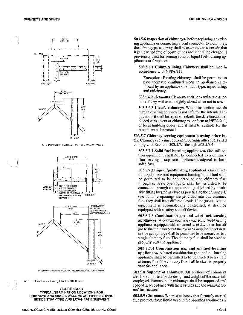
CHIMNEYS AND VENTS
2 FT M\N '~ CHIMNEY
RIDGE
10 FT OR LESS
-.-2 FT MIN. _L
·'• WALLOR .. PARAPET
/.·.
CHIMNEY
I m I MIN
I c+-J 1W I I
CHIMNEY
A TERMINATION 10 FT OR LESS FROM RIDGE, WALL, OR PARAPET
RIDGE
-T I 3 FT
:i I ~ I I
r MORE THAN HEIGHT ABOVE -~"'10"n""''~--< ANY ROOF
SURFACE WITHIN
~ FTT --7'-1-0FT~·HORIZONTALLY
I 2FTMIN. i :l I ~iJ I I I I I
: I~. CHIMNE~ ~
B. TERMINATION MORE THAN 10 FT FROM RIDGE, WALL, OR PARAPET
For SI: I inch= 25.4 mm, 1 foot= 304.8 mn1.
FIGURE 503.5.4 TYPICAL TERMINATION LOCATIONS FOR
CHIMNEYS AND SINGLE-WALL METAL PIPES SERVING RESIDENTIAL-TYPE AND LOW-HEAT EQUIPMENT
2002 WISCONSIN ENROLLED COMMERCIAL BUILDING CODE
FIGURE 503.5.4 - 503.5.9
503.5.6 Inspection of chimneys, Before replacing an existing appliance or connecting a vent connector to a chi1nney, the chimney passageway shall be examined to ascertain that it is clear and free of obstructions and it shall be cleaned if previously used for venting solid or liquid fuel-burning appliances or fireplaces.
503,5.6.1 Chimney lining. Chiim1eys shall be lined in accordance with NFPA 211.
Exception: Existing chimneys shall be permitted to have their use continued when an appliance is replaced by an appliance of similar type, input rating, and efficiency.
503,5.6.2 Cleanonts. Cleanouts shall be examined to determine if they will remain tightly closed when not ill use.
503,5.6.3 Unsafe chimneys. Where inspection reveals that an existmg chimney is not safe for the intended application, it shall be repaired, rebuilt, lined, relined, or replaced with a vent or chimney to conform to NFPA 211, or local building codes, and it shall be suitable for the equipment to be vented.
503.5.7 Chimney serving equipment burning other fu. els. Chimneys serving equipment burning other fuels shall comply with Sections 503.5.7.1through503.5.7.4.
503,5.7.1 Solid fuel-burning appliances. Gas utilization equipment shall not be connected to a chimney flue serving a separate appliance designed to burn solid fuel.
503.5,7 .2 Liquid fuel-burning appliances. Gas utilization equipment and equipment burning liquid fuel shall be permitted to be connected to one chimney flue through separate openings or shall be permitted to be connected through a single opening if joined by a suitable fitting located as close as practical to the chimney. If two or more openings are provided into one chinmey flue, they shall be at different levels. If the gas utilization equipment is automatically controlled, it shall be equipped with a safety shutoff device.
503.5,7.3 Combination gas and solid fuel-burning appliances. A combination gas- and solid fuel-burning appliance equipped with a manual reset device to shut off gas to the main burner in the event of sustained backdraft or flue gas spillage shall be permitted to be connected to a single chimney flue. The chimney flue shall be sized to properly vent the appliance.
503.5,7.4 Combination gas and oil fuel-burning appliances. A listed combination gas- and oil-burning appliance shall be permitted to be connected to a single chimney flue. The chimney flue shall be sized to properly vent the appliance.
503.5.8 Support of chimneys. All portions of chimneys shall be supported for the design and weight of the materials employed. Factory-built chimneys shall be supported and spaced in accordance with their listings and the tnanufacturersi instructions.
503.5.9 Cleanouts. Where a chimney that formerly carried flue products from liquid or solid fuel-burning appliances is
FG-31

503.5.10-503.6.7
used with an appliance using fuel gas, an accessible cleanout shall be provided. The cleanout shall have a tightfitting cover and shall be installed so its upper edge is at least 6 inches ( 152 mm) below the lower edge of the lowest chimney inlet opening.
503.5.10 Space surrounding lining or vent. The remaining space sun·ounding a chimney liner, gas vent, special gas vent, or plastic piping installed within a masomy chimney flue shall not be used to vent another appliance.
Exception: The insertion of another liner or vent within the chimney as provided in this code and the liner or vent inanufacturer's instructions.
503.6 Gas vents. Gas vents shall comply with Sections 503 .6.1 through 503.6.12 (see Section 202, Definitions).
503.6.1 Installation, general. Gas vents shall be installed in accordance with the terms of their listings and the manufacturers' instructions.
503.6.2 Type B-W vent capacity. A Type B-W gas vent shall have a listed capacity not less than that of the listed vented wall furnace to which it is connected.
503.6.3 Roof penetmtion. A gas vent passing through a roof shall extend through the roof flashing, roof jack, or roof thimble and shall be terminated by a listed termination cap.
503.6.4 Offsets. rype B and Type L vents shall extend in a generally vertical direction with offsets not exceeding 45 degrees (0.79 rad), except that a vent system having not more than one 60-degree (1.04 rad) offset shall be permitted. Any angle greater than 45 degrees (0.79 rad) from the vertical is considered horizontal. The total horizontal length of a vent plus the horizontal vent connector length serving draft hood-equipped appliances shall not be greater than 75 percent of the vertical height of the vent.
Exception: Systems designed and sized as provided in Section 504 or in accordance with other approved engineering methods.
Vents serving Category I fan-assisted appliances shall be installed in accordance with the appliance manufacturers' instructions and Section 504 or other approved engineering methods.
503.6.5 Gas vents installed within masonry chimneys. Gas vents installed within masomy chimneys shall be installed in accordance with the terms of their listing and the manufacturers' installation instructions. Gas vents installed within masonry chimneys shall be identified with a permanent label installed at the point where the vent enters the chimney. The label shall contain the following language: ''This gas vent is for appliances that burn gas. Do not connect to solid or liquid fuel-burning appliances or incinerators."
503.6.6 Gas vent terminations. A gas vent shall terminate above the roof surface with a listed cap or listed roof assembly. Gas vents 12 inches (305 mm) in size or smaller with listed caps shall be permitted to be terminated in accordance with Figure 503.6.6, provided that such vents are at least 8 feet (2438 mm) from a vertical wall or similar obstruction.
FG-32
CHIMNEYS AND VENTS
r H(MIN_)-MINIMliM HEIGHT FROM ROOF TO LOWEST DISCHARGE OPENING
ROOF PITCH H (min) ft
Flat to 6/12 1.0
6/12 to 7/12 1.25
Over 7/12 to 8/12 1.5
Over 8/12 to 9/12 2.0
Over 9/12 to 10/12 2.5
Over 10/12 to 11/12 3.25
Over 11/12 to 12/12 4.0
Over 12/12 to 14/12 5.0
Over 14/12 to 16/12 6.0
Over 16/12 to 18/12 7.0
Over 18/12 to 20/12 7.5
Over 20/12 to 21/12 8.0
For SI: 1 inch= 25.4 1nm, 1 foot= 304.8 mm.
FIGURE 503.6.6 GAS VENT TERMINATION LOCATIONS FOR
LISTED CAPS 12 INCHES OR LESS IN SIZE AT LEAST 8 FEET FROM A VERTICAL WALL
All other gas vents shall terminate not less than 2 feet (610 mm) above the highest point where they pass through the roof and at least 2 feet (610 mm) higherthan any portion of a building within 10 feet (3048 mm).
Exceptions:
I. Industrial equipment as provided in Section 503.2.2.
2. Direct vent systems as provided in Section 503.2.3.
3. Equipment with integral vents as provided in Section 503.2.4.
4, Mechanical draft systems as provided in Section 503.3.3.
5, Ventilating hoods and exhaust systems as provided in Section 503.3.4.
503.6.7 Minimum height. A Type B or a Type L gas vent shall terminate at least 5 feet (1524 mm) in vertical height above the highest connected equipment draft hood or flue col-
2002 WISCONSIN ENROLLED COMMERCIAL BUILDING CODE

CHIMNEYS AND VENTS
Jar. A Type B-W gas vent shall terminate at least 12 feet (3658 mm) in vertical height above the bottom of the wall furnace.
503.6.8 Exterior wall penetrations. A gas vent extending through an exterior wall shall not terminate adjacent to the wall or below eaves or parapets, except as provided in Sections 503.2.3 and 503.3.3.
503.6.9 Size of gas vents. Venting systems shall be sized and constructed in accordance with Section 504 or other approved engineering methods and the gas vent and gas equipment inanufacturers' instructions.
503.6.9.l Category I appliances. The sizing of natural draft venting systems serving one or more listed appliances equipped with a draft hood or appliances listed for use with Type B gas vent, installed in a single story of a building, shall be in accordance with Section 504 or in accordance with sound engineering practice. Category I appliances are either draft hood-equipped or fan-assisted combustion system in design. Different vent design methods are required for draft hood equipped and fan-assisted combustion system appliances.
Exceptions:
1. As an alternate method for sizing an individual gas vent for a single, draft hood-equipped appliance, the effective area of the vent connector and the gas vent shall be not less than the area of the appliance draft hood outlet, nor greater than seven times the draft hood outlet area. Vents serving fan-assisted combustion system appliances shall be sized in accordance with Section 504 or other approved engineering methods.
2. As an alternate 1nethod for sizing a gas vent connected to two appliances with draft hoods, the effective area of the vent shall be not less than the area of the larger draft hood outlet plus 50 percent of the smaller draft hood outlets, nor greater than seven tiines the smallest draft hood outlet area. Vents serving fan-assisted combustion syste1n appliances, or combinations of fanassisted combustion systetn and draft hoodequipped appliances, shall be sized in accordance with Section 504 or other approved engineering methods.
503.6.9.2 Category II, III, and IV appliances. The sizing of gas vents for Categmy II, III, and IV equipment shall be in accordance with the equipment manufacturers' instructions.
503.6,10 Gas vents serving equipment on more than one floor. A single or con1mon gas vent shall be permitted in n1ultistory installations to vent Category I equip1nent located on more than one floor level, provided the venting system is designed and installed in accordance with this section and approved engineering n1ethods.
503.6.10.1 Equipment separntion. All equipment connected to the com1non vent shall be located in rooms separated from habitable space. Each of these rooms shall have provisions for an adequate supply of co1nbustion,
2002 WISCONSIN ENROLLED COMMERCIAL BUILDING CODE
OUTSIDE BALCONY OR SERVICE AREA
503.6.8-503.7.1
-TYPE B GAS VENTS
,. AIR GR!LlS IN OUTSIDE WALL
- - LOUVERED DOOR PERMITIED TO BE USED IN LIEU OF OUTSIDE WALL GRILLS
FIGURE 503.6.10.1 PLAN VIEW OF PRACTICAL SEPARATION METHOD
FOR MULTISTORY GAS VENTING
ventilation, and dilution air that is not supplied from habitable space (see Figure 503.6.10.1).
503.6.10.2 Sizing. The size of the connectors and common seg1nents of multistory venting systems for equipment listed for use with Type B double-wall gas vent shall be in accordance with Table 504.3(1) and Figures B-13 and B-14 in Appendix B, provided:
1. The available total height (H) for each segment ofa multistory venting syste1n is the vertical distance between the level of the highest draft hood outlet or flue collar on that floor and the centerline of the next highest interconnection tee (see Figure B-13).
2. The size of the connector for a segment is determined fro1n its gas utilization equip1nent heat input and available connector rise, and shall not be smaller than the draft hood outlet or flue collar size.
3. The size of the com1non ve1tical segment, and of the interconnection tee at the base of that segment, shall be based on the total gas utilization equipment heat input entering that segn1ent and its available total height.
503.6.11 Support of gas vents. Gas vents shall be supported and spaced in accordance with their listings and the manufacturers' instructions.
503.6.12 Marking. In those localities where solid and liquid fuels are used extensively, gas vents shall be permanently identified by a label attached to the wall or ceiling at a point where the vent connector enters the gas vent. The deter1nination of where such localities exist shall be made by the code official. The label shall read:
"This gas vent is for appliances that burn gas. Do not connect to solid or liquid fuel-burning appliances or incinerators."
503.7 Single-wall metal pipe. Single-wall metal pipe vents shall comply with Sections 503.7.l through 503.7.12.
503.7.1 Construction. Single-wall metal pipe shall be constructed of galvanized sheet steel not less than 0.0304 inch
FG-33

503.7.2 -503.8
" (0. 7 mm) thick, or other approved, noncombustible, cmTo-sion-resistant material.
503.7.2 Cold climate. Uninsulated single-wall metal pipe shall not be used outdoors in cold climates for venting gas utilization equiptnent.
503.7.3 Termination. Single-wall metal pipe shall terminate at least 5 feet (1524 mm) in vertical height above the highest connected equipment draft hood outlet or tlue collar. Single-wall metal pipe shall extend at least 2 feet (610 mm) above the highest point where it passes through a roof of a building and at least 2 feet (610 mm) higher than any portion of a building within a horizontal distance of 10 feet (3048 mm) (see Figure 503.5.4). An approved cap or roof assembly shall be attached to the terminus of a single-wall metal pipe (see also Section 503.7.8, Item 3).
503.7 .4 Limitations of use. Single-wall metal pipe shall be used only for runs directly from the space in which the equipment is located through the roof or extelior wall to the outdoor atmosphere.
503.7.5 Roof penetrations. A pipe passing through a roof shall extend without interruption through the roof flashing, roof jacket, or roof thimble. Where a single-wall metal pipe passes through a roof constructed of con1bustible material, a nonco1nbustible, nonventilating thin1ble shall be used at the point of passage. The thimble shall extend at least 18 inches (457 mm) above and 6 inches (152 mm) below the roof with the annular space open at the bottom and closed only at the top. The thimble shall be sized in accordance with Section 503.10.16.
CHIMNEYS AND VENTS
pipe to combustible material shall be permitted to be reduced where the combustible mate1ial is protected as specified for vent connectors in 'P&ble 308.2.
503.7.8 Size of single-wall metal pipe. A venting system constrncted of single-wall metal pipe shall be sized in accordance with one of the following methods and the equipment manufacturer's inst.ructions:
I. For a draft hood-equipped appliance, in accordance with Section 504.
2. For a venting system for a single appliance with a draft hood, the areas of the connector and the pipe each shall be not less than the area of the appliance tlue collar or draft hood outlet, whichever is smaller. The vent area shall not be greater than seven times the draft hood outlet area.
3. Other approved engineering methods.
503.7.9 Pipe geometry. Any shaped single-wall metal pipe shall be permitted to be used, provided that its equivalent effective area is equal to the effective area of the round pipe for which it is substituted, and provided that the minimum internal dimension of the pipe is not less than 2 inches (51 mm).
503.7.10 Termination capacity. The vent cap or a roof assembly shall have a venting capacity not less than that of the pipe to which it is attached.
503.7.11 Support of single-wall metal pipe. All portions of single-wall metal pipe shall be supported for the design and weight of the material employed.
503.7.12 Marking. Single-wall metal pipe shall comply with the marking provisions of Section 503.6.12. 503.7.6 Installation. Single-wall metal pipe shall not origi
nate in any unoccupied attic or concealed space and shall not pass through any attic, inside wall, concealed space, or t1oor. The installation of a single-wall metal pipe through an exterior combustible wall shall comply with Section 503. I 0. 16. Single-wall metal pipe used for venting an incinerator shall be exposed and readily examinable for its full length and shall have suitable clearances 1naintained.
503.8 [Comm 65.0503 (2)] Venting system termination location. The location of venting system terminations shall comply with the following (see Appendix C):
503.7.7 Clearances. Minimu1n clearances fro1n single-wall metal pipe to combustible 1naterial shall be in accordance with Table 503.7.7. The clearance from single-wall metal
1. The separation between gravity and mechanical air inlets and venting system terminations shall comply with IMC Section 401.5.1 ands. Comm 64.0401 (4).
Exceptions:
1. This provision shall not apply to the combustion air intake of a direct-vent appliance.
TABLE 503.7.7' CLEARANCES FOR CONNECTORS
MINIMUM DISTANCE FROM COMBUSTIBLE MATERIAL
Listed Type B gas Listed Type I Single-wall Factory-built EQUIPMENT vent malerlal vent material metal pipe chimney sections
Listed equiprnent with draft hoods and equipinent listed for use As listed As listed 6 inches As listed
with Tvne B gas vents
Residential boilers and furnaces with listed gas conversion burner 6 inches 6 inches 9 inches As listed
and with draft hood
Residential annliances listed for use with Tune L vents Not oermitted As listed 9 inches As listed
Residential incinerators Not oennitted 9 inches 18 inches As listed
Listed e:as-fired toilets Not oern1itted As listed As listed As listed
Unlisted residential anr>liances with draft hood Not nermitted 6 inches 9 inches As listed
Residential and low-heat eouipment other than above Not permitted 9 inches 18 inches As listed
Mediun1-heat equipment Not permitted Not permitted 36 inches As listed
For SI: I inch= 25.4 nlm. a. These clearances shall apply unless the listing of an appliance or connector specifies different clearances, in which case the listed clearances shall apply.
FG-34 2002 WISCONSIN ENROLLED COMMERCIAL BUILDING CODE

CHIMNEYS AND VENTS
2. This provision shall not apply to the separation of the integral outdoor air inlet and flue gas discharge of listed outdoor appliances.
2. Unless a greater distance is specified by the manufacturer, mechanical draft venting systems shall terminate at least 12 inches (305 rmn) vertically from the adjoining grade level.
3. The vent tenninal of a direct-vent appliance with an input of 10,000 Btu per hour (3 kW) or less shall be located at least 6 inches (152 mm) from any air opening into a building, and such an appliance with an input over 10,000 Btu per hour (3 kW) but not over 50,000 Btu per hour (14.7 kW) shall be installed with a 9 inch (230 mm) vent termination clearance, and an appliance with an input over 50,000 Btu/h (14.7 kw) shall have at least a 12-inch (305 mm) vent termination clearance. The bottom of the vent terminal and the air intake shall be located at least 12 inches (305 mm) above grade.
4. Through-the-wall vents for Category II and IV appliances and noncategorized condensing appliances shall not terminate over public walkways or over an area where condensate or vapor could create a nuisance or hazard or could be detrimental to the operation of regulators, relief valves, or other equipment. Where local experience indicates that condensate is a problem with Category I and ill appliances, this provision shall also apply.
503.9 Condensation drainage. Provision shall be made to collect and dispose of condensate frotn venting systems serving Category II and IV equipment and noncategorized condensing appliances in accordance with Section 503.8(4). Where local experience indicates that condensation is a problem, provision shall be made to drain off and dispose of condensate from venting systems serving Category I and III equipment in accordance with Section 503.8(4).
503.10 Vent connectors for Category I equipment. Vent connectors for Category I equipment shall comply with Sections 503.10.1through503.10.17.
503.10.1 Where required. A vent connector shall be used to connect equipment to a gas vent, chimney, or single-wall metal pipe, except where the gas vent, chimney, or singlewall metal pipe is directly connected to the equipment.
503.10.2 Materials. Vent connectorn shall be constmcted in accordance with Sections 503.10.2.1 through 503.10.2.5.
503.10,2.1 General. A vent connector shall be made of noncombustible corrosion-resistant material capable of withstanding the vent gas temperature produced by the equipment and of sufficient thickness to withstand physical damage.
503.10.2.2 Vent connectors located in unconditioned areas. Where the vent connector used for equipment having a draft hood or a Category I appliance is located in or passes through an attic space or other unconditioned area, that portion of the vent connector shall be listed Type B or Type L or listed vent material or listed material having equivalent insulation qualities.
503.10.2.3 Residential-type appliance connectors. Where vent connectors for residential-type appliances
2002 WISCONSIN ENROLLED COMMERCIAL BUILDING CODE
503.9-503.10.2.5
are not installed in attics or other unconditioned spaces, connectors for listed appliances having draft hoods and for appliances having draft hoods and equipped with listed conversion burners shall be one of the following:
1. Type B or Type L vent material;
2. Galvanized sheet steel not less than 0.018 inch (0.46 mm) thick;
3. Aluminum (1100 or 3003 alloy or equivalent) sheet not less than 0.027 inch (0.69 mm) thick;
4. Stainless steel sheet not less than 0.012 inch (0.31 mm) thick;
5. Smooth interior wall metal pipe having resistance to heat and conosion equal to or greaterthan that of Item 2, 3 or 4 above; or
6. A listed vent connector.
Vent connectors shall not be covered with insulation.
Exception: Listed insulated vent connectors shall be installed according to the terms of their listing.
503.10.2.4 Low-heat equipment. A vent connector for low-heat equipment shall be a factmy-built chimney section or steel pipe having resistance to heat and corrosion equivalent to that for the appropriate galvanized pipe as specified in Table 503.10.2.4. Factory-built chimney sections shall be joined together in accordance with the chimney manufacturers' instructions.
TABLE 503.10.2.4 MINIMUM THICKNESS FOR GALVANIZED STEEL VENT
CONNECTORS FOR LOW-HEAT APPLIANCES
DIAMETER OF CONNECTOR MINIMUM THICKNESS (Inches) (inch)
Less than 6 0.019
6 to less than 10 0.023
10 to 12 inclusive 0.029
14 to 16 inclusive 0.034
Over 16 0.056
1-<0r SI: 1 inch:= 25.4 mm.
503.10.2.5 Medium-heat appliances. Vent connectors for medium-heat equipment and commercial and industrial incinerators shall be constructed of factmy-built medium-heat chimney sections or steel of a thickness not less than that specified in Table 503.10.2.5 and shall comply with the following:
I. A steel vent connector for equipment with a vent gas temperature in excess of 1000°F (538°C), 1neasured at the entrance to the connector, shall be lined with medium duty fire brick (ASTM C 64, Type F), or the equivalent.
2. The lining shall be at least 2 1/ 2 inches (64 mm) thick for a vent connector having a diameter or greatest cross-sectional dimension of 18 inches (457 mm) or less.
3. The lining shall be at least 4 1/ 2 inches (114 mm) thick laid on the 4 1/ 2-inch (114 mm) bed for a vent
FG-35

TABLE 503.10.2.5-503.10.10
connector having a diameter or greatest cross-sectional dimension greaterthan 18 inches ( 457 mm).
4. Factory-built chimney sections, if employed, shall be joined together in accordance with the chimney manufacturers' instructions.
TABLE 503.10.2.5 MINIMUM THICKNESS FOR STEEL VENT CONNECTORS FOR
MEDIUM-HEAT EQUIPMENT AND COMMERCIAL AND INDUSTRIAL INCINERATORS VENT CONNECTOR SIZE
DIAMETER AREA MINIMUM THICKNESS (inches) (square inches) (inch)
Up to 14 Up to 154 0.053
Over 14 to 16 154 to 201 0.067
Over 16 to 18 201to254 0.093
Over 18 Larger than 254 0.123
For SI: 1inch=25.4 mn1, I square inch= 645.16 mrn2.
503.10.3 Size of vent connector. Vent connectors shall be sized in accordance with Sections 503.10.3.1 through 503.10.3.6.
FG-36
503.10.3.1 Single draft hood and fan-assisted. A vent connector for equipment with a single draft hood or for a Category I fan-assisted co1nbustion system appliance shall be sized and constructed in accordance with Section 504 and other approved engineering methods.
503.10.3.2 Multiple draft hood. For a single appliance having more than one draft hood outlet or flue collar, the manifold shall be constructed according to the instructions of the appliance inanufacturer. If there are no instructions, the manifold shall be designed and constructed in accordance with approved engineering practices. As an alternate method, the effective area of the manifold shall equal the combined area of the flue collars or draft hood outlets and the vent connectors shall have a minimum ]-foot (305 mm) dse.
503.10.3.3 Multiple appliances. Where two or more appliances are connected to a com1non vent or chimney, each vent connector shall be sized in accordance with Section 504 or other approved engineering methods.
As an alternative method applicable only when all of the appliances are draft hood equipped, each vent connector shall have an effective area not less than the area of the draft hood outlet of the appliance to which it is connected.
503.10.3.4 Common connector/manifold. Where two or more gas appliances are vented through a common vent connector or vent manifold, the common vent connector or vent manifold shall be located at the highest level consistent with available headroom and the required clearance to combustible materials and shall be sized in accordance with Section 504 or other approved engineering methods.
As an alternate method applicable only where there are two draft hood equipped appliances, the effective area of the common vent connector or vent manifold and all junction fittings shall be not less than the area of the
CHIMNEYS AND VENTS
larger vent connector plus 50 percent of the areas of the smaller flue collar outlet.
503.10.3.5 Size increase. Where the size of a vent connector is increased to overco1ne installation limitations and obtain connector capacity equal to the equipment input, the size increase shall be made at the equipment draft hood outlet.
503.10.3.6 Approved engineering practices. The effective area of the vent connector, where connected to one or more appliances requiring draft for operation, shall be obtained by the application of approved engineering practices to perform as specified in Sections 503.3 and 503.3.1.
503.10.4 1\vo or more appliances connected to a single vent. Where two or more vent connectors enter a common gas vent, chimney flue, or single-wall metal pipe, the smaller connector shall enter at the highest level consistent with the available headroom or clearance to combustible material. Vent connectors serving Category I appliances shall not be connected to any portion of a mechanical draft syste1n operating under positive static pressure, such as those serving Category ill or IV appliances.
503.10.5 Clearance. Minimum clearances from vent connectors to co1nbustible material shall be in accordance with Table 503.7.7.
Exception: The clearance between a vent connector and combustible material shall be permitted to be reduced where the combustible material is protected as specified for vent connectors in Table 308.2.
503.10.6 Flow resistance. A vent connector shall be installed so as to avoid turns or other construction features that create excessive resistance to flow of vent gases.
503.10.7 Joints. Joints between sections of connector piping and connections to flue collars and hood outlets shall be fastened by sheet-1netal screws or other approved means.
Exception: Vent connectors of listed vent tnaterial, assembled and connected to flue collars and draft hood outlets in accordance with the manufacturers' instructions.
503.10.8 Slope. A vent connector shall be installed without dips or sags and shall slope upward toward the vent or chimney at least 1/ 4 inch per foot (21 mm/m).
503.10.9 Length of vent connector. A vent connector shall be as short as practical and the equipment located as close as practical to the chimney or vent. Except as provided for in Section 503.10.3, the maximum horizontal length of a single-wall connector shall be 75 percent of the height of the chimney or vent. Except as provided for in Section 503.10.3, the maximum horizontal length of a Type B double-wall connector shall be 100 percent of the height of the chimney or vent. For a chimney or vent system serving multiple appliances, the 1naximum length of an individual connector, from the appliance outlet to the junction with the common vent or another connector, shall be 100 percent of the height of the chimney or vent.
503.10.10 Support. A vent connector shall be supported for the design and weight of the material employed to maintain
2002 WISCONSIN ENROLLED COMMERCIAL BUILDING CODE

CHIMNEYS AND VENTS
clearances and prevent physical damage and separation of joints.
503.10.11 Location. Where the vent connector used for equipment having a draft hood or for Category I appliances is located in or passes through an attic, crawl space, or other unconditioned area subject to low ambient te1nperatures, that portion of the vent connector shall be of listed doublewall Type B, Type L vent material or listed material having equivalent insulation qualities.
503.10.12 Chimney connection. Where entering a flue in a masonry or metal chimney, the vent connector shall be installed above the extreme bottom to avoid stoppage. A thimble or slip joint shall be permitted to be used to facilitate removal of the connector. The connector shall be firmly attached to or inserted into the thimble or slip joint to prevent the connector from falling out. Means shall be employed to prevent the connector from entering so far as to restrict the space between its end and the opposite wall of the chinmey flue (see Section 501.9).
503.10.13 Inspection. The entire length of a vent connector shall be provided with ready access for inspection, cleaning, and replacement.
503.10.14 Fireplaces. A vent connector shall not be connected to a chimney flue serving a fireplace unless the fireplace flue opening is permanently sealed.
503.10.15 Passage through ceilings, floors, or walls. A vent connector shall not pass through any ceiling, floor or fire-resistance rated wall . A single-wall metal pipe connector shall not pass through any interior wall.
Exception: Vent connectors made of listed Type B or Type L vent material and serving listed equipment with draft hoods and other equipment listed for use with Type B gas vents shall be permitted to pass through walls or partitions constructed of combustible material if the connectors are installed with not less than the listed clearance to co1nbustible material.
503.10.16 Single-wall connector penetrations of combustible walls. A vent connector made of a single-wall metal pipe shall not pass through a combustible exterior wall unless guarded at the point of passage by a ventilated metal thimble not smaller than the following:
I. For listed equipment equipped with draft hoods and equipment listed for use with Type B gas vents, the thimble shall be not less than 4 inches (102 mm) larger in dia1neter than the vent connector. Where there is a runofnotless than6 feet (1829 mm) of vent connector in the open between the draft hood outlet and the thimble, the thimble shall be permitted to be not less than 2 inches (51 mm) larger in diameter than the vent connector.
2. For unlisted equipment having draft hoods, the thimble shall be not less than 6 inches (152 mm) larger in dia1neter than the vent connector.
3. For residential incinerators and all other residential and low-heat equipment, the thimble shall be not less than 12 inches (305 mm) larger in diameter than the vent connector.
2002 WISCONSIN ENROLLED COMMERCIAL BUILDING CODE
503.10.11-503.12.5
Exception: In lien of thimble protection, all combustible material in the wall shall be removed fro1n the vent connector a sufficient dis lance to provide the specified clearance from such vent connector to cotnbustible material. Any material used to close up such opening shall be nonco1nbustible.
503.10.17 Medium-heat connectors. Vent connectors for medium-heat equipment shall not pass through walls or partitions constructed of combustible 1naterial.
503.11 Vent connectors for Category II, III, and IV gas utilization equipment. Vent connectors for Category II, III and IV appliances shall be as specified for the venting systems in accordance with Section 503.4.
503.12 Draft hoods and draft controls. The installation of draft hoods and draft controls shall comply with Sections 503.12.1 through 503.12.8.
503.12.1 Equipment requiring draft hoods. Vented equipment shall be installed with draft hoods.
Exception: Dual oven type combination ranges, incinerators, direct-vent equiptnent, fan-assisted combustion system appliances, equipment requiring chimney draft for operation, single firebox boilers equipped with conversion burners with inputs greater than 400,000 Btu per hour (117 kw), equipment equipped with blast, power, or pressure burners that are not listed for use with draft hoods, and equipment designed for forced venting.
503.12.2 Installation. A draft hood supplied with or forming a part oflisted vented equipment shall be installed without alteration, exactly as furnished and specified by the equipment manufacturer. If a draft hood is not supplied by the equipment manufacturer where one is required, a draft hood shall be installed, shall be of a listed or approved type and, in the absence of other instructions, shall be of the same size as the equipment flue collar. Where a draft hood is required with a conversion burner, it shall be of a listed or approved type.
Exception: Where it is determined that a draft hood of special design is needed or preferable for a particular installation, the installation shall be in accordance with the recommendations of the equipment manufacturer and shall be approved.
503.12.3 Draft control devices. Where a draft control device is part of the equipment or is supplied by the equipment manufacturer, it shall be installed in accordance with the inanufacturers' instructions. In the absence of manufacturern' instructions, the device shall be attached to the flue collar of the equipment or as near to the equipment as practical.
503.12.4 Additional devices. Equipment (except incinerators) requiring controlled chimney draft shall be permitted to be equipped with a listed double-acting bm·ometric-draft regulator installed and adjusted in accordance with the manufacturers' instructions.
503.12.5 Incinerator draft regnlato1' A listed incinerator shall be permitted to be equipped with a listed single-acting barometric draft regulator where recommended by the incinerator manufacturer. This draft regulator shall be installed in accordance with the incinerator 1nanufacturer's instructions.
FG-37

503.12.6 -504.2.2
503.12.6 Location. Draft hoods and barometric draft regulators shall be installed in the same room or enclosure as the equipment in such a manner as to prevent any difference in pressure between the hood or regulator and the combustion air supply.
503.12.7 Positioning. Draft hoods and draft regulators shall be installed in the position for which they were designed with reference to the horizontal and vertical planes and shall be located so that the relief opening is not obstructed by any part of the equipment or adjacent construction. The equipment and its draft hood shall be located so that the relief opening is accessible for checking vent operation.
503.12.8 Clearance. A draft hood shall be located so its reliefopening is notless than 6 inches (152 mm) from any surface except that of the equipment it serves and the venting system to which the draft hood is connected. Where a greater or lesser clearance is indicated on the equipment label, the clearance shall be not less than that specified on the label. Such clearances shall not be reduced.
503.13 Manually operated dampers. A manually operated damper shall not be placed in the vent connector for any equip-1nent, except in a connector serving a listed incinerator where recommended by the incinerator manufacturer and installed in accordance with the incinerator inanufacturer's instructions. Fixed baffles shall not be classified as manually operated dampers.
503.14 Automatically operated vent dampers. An automatically operated vent damper shall be of a listed type.
503.15 Obstructions. A device that retards the flow of vent gases shall not be installed in a vent connector, chimney, or vent. The tables in Section 504 shall not apply where the devices covered in this section are installed in the vent. Other approved engineering methods shall be used to size such vents.
Exceptions:
1. Draft regulators and safety controls specifically listed for installation in venting systems and installed in accordance with the terms of their listing.
2. Draft regulators and safety controls that are designed and installed in accordance with approved engineering methods and that are approved.
3. Listed heat reclaimers and automatically operated vent da1npers installed in accordance with the terms of their listing.
4. Approved economizers, heat reclaimers, and recuperators installed in venting systems of equipment not required to be equipped with draft hoods, provided the gas utilization equipment manufacturer's instructions cover the installation of such a device in the venting system and performance in accordance with Sections 503.3 and 503.3. l is obtained.
SECTION 504 (IFGS) SIZING OF CATEGORY I APPLIANCE
VENTING SYSTEMS
504.1 Definitions. The following definitions apply to the tables in this section.
FG·3B
CHIMNEYS AND VENTS
Appliance categorized vent diameter/area. The minimum vent area/diameter permissible for Category I appliances to maintain a nonpositive vent static pressure when tested in accordance with nationally recognized standards.
Fan-assisted combustion system. An appliance equipped with an integral mechanical means to either draw or force products of combustion through the combustion chamber or heat exchanger.
FAN Min. The minimum input rating of a Category I fan-assisted appliance attached to a vent or connector.
FAN Max. The maximum input rating of a Category I fanassisted appliance attached to a vent or connector.
NAT Max. The maximum input rating of a Category I drafthood-equipped appliance attached to a vent or connector.
FAN+ FAN. The maximum combined appliance input rating of two or more Category I fan-assisted appliances attached to the co1nmon vent.
FAN+ NAT. The maximum combined appliance input rating of one or more Category I fan-assisted appliances and one or more Category I draft-hood-equipped appliances attached to the common vent.
NA. Vent configuration is not allowed due to potential for condensate formation or pressurization of the venting system, or not applicable due to physical or geometric restraints.
NAT+ NAT. The maximum combined appliance input rating of two or more Category I draft-hood-equipped appliances attached to the common vent.
504.2 Application of single-appliance vent Tables 504.2(1) through 504.2(5). The application of Tables 504.2(1) through 504.2(5) shall be subject to the requirements of Sections 504.2.l through 504.2.13.
504.2.1 Vent obstructions. These venting tables shall not be used where obstructions, as described in the exceptions to Section 503.15, are installed in the venting system. The installation of vents serving listed appliances with vent dampers shall be in accordance with the appliance manufacturer's instructions or in accordance with the following:
I. The maximum capacity of the vent system shall be determined using the "NAT Max" column.
2. The minimum capacity shall be determined as if the appliance were a fan-assisted appliance, using the "FAN Min" column to determine the minimum capacity of the vent system. Where the cmrnsponding "FAN Min" is "NA;' the vent configuration shall not be permitted and an alternative venting configuration shall be utilized.
504.2.2 Minimum size. Where the vent size determined from the tables is smaller than the appliance draft hood outlet or flue collar, the smaller size shall be permitted to be used provided all of the following requirements are met:
I. The total vent height (H) is at least 10 feet (3048 mm).
2. Vents for appliance draft hood outlets or flue collars 12 inches (305 mm) in diameter or smaller are not reduced more than one table size.
2002 WISCONSIN ENROLLED COMMERCIAL BUILDING CODE
CHIMNEYS AND VENTS
3. Vents for appliance draft hood outlets or flue collars larger than 12 inches (305 mm) in diameter are not reduced more than two table sizes.
4. The maximum capacity listed in the tables for a fanassisted appliance is reduced by 10 percent (0.90 x maximum table capacity).
5. The draft hood outlet is greater than 4 inches (102 mm) in diameter. Do not connect a 3-inch (76 mm) diameter vent to a 4-inch-diameter (102 mm) draft hood outlet. This provision shall not apply to fan-assisted appliances.
504.2.3 Vent offsets. Single-appliance venting configurations with zero (0) lateral lengths in Tables 504.2(1 ), 504.2(2), and 504.2(5) shall not have elbows in the venting system. For vent configurations with lateral lengths, the venting tables include allowance for two 90-degree turns. For each additional 90-degree (1.6 rad) turn, or equivalent, the maximum capacity listed in the venting tables shall be reduced by 10 percent (0.90 x maximum table capacity). Two or more turns, the combined angles of which equal 90-degrees, shall be considered equivalent to one 90-degree (J.6 rad) turn.
504.2.4 Zero lateral. Zero (0) lateral (L) shall apply only to a straight vertical vent attached to a top outlet draft hood or flue collar.
504.2.5 High-altitude installations. Sea-level input ratings shall be used when determining maximum capacity for high altitude installation. Actual input (derated for altitude) shall be used for determining minimum capacity for high altitude installation.
504.2.6 Multiple input rate appliances. For appliances with more than one input rate, the minimum vent capacity (FAN Min) determined from the tables shall be less than the lowest appliance input rating, and the inaximum vent capacity (FAN Max/NAT Max) determined from the tables shall be greater than the highest appliance rating input.
504.2.7 Liner system sizing. Listed corrugated metallic chimney liner systems in masonry chimneys shall be sized by using Table 504.2(1) or 504.2(2) for Type B vents with the maximum capacity reduced by 20 percent(0.80 x maximum capacity) and the minimum capacity as shown in Table 504.2(1) or 504.2(2). Corrugated metallic liner systems installed with bends or offsets shall have their maximum capacity further reduced in accordance with Section 504.2.3.
504.2.8 Vent area and diameter. Where the vertical vent has a larger diameter than the vent connector, the vertical vent diameter shall be used to determine the minimum vent capacity, and the connector diameter shall be used to determine the maximu1n vent capacity. The flow area of the vertical vent shall not exceed seven times the flow area of the listed appliance categorized vent area, flue collar area, or draft hood outlet area unless designated in accordance with approved engineering methods.
2002 WISCONSIN ENROLLED COMMERCIAL BUILDING CODE
504.2.3 - 504.3
504.2.9 Chimney and vent locations. Tables 504.2(1), 504.2(2), 504.2(3), 504.2(4) and 504.2(5) shall be used for chimneys and vents not exposed to the outdoors below the roof line. A 'fype B vent or listed chimney lining system passing through an unused masonry chimney flue shall not be considered to be exposed to the outdoors. Table 504.2(3) in combination with Table 504.3(6) shall be used for claytile-lined exterior masonry chimneys, provided all of the following are met:
1. Vent connector is 'fype B double-wall.
2. Vent connector length is limited to 1 1/ 2 feet for each inch (18 mm per mm) of vent connector diameter.
3. The appliance is draft hood equipped.
4. The input rating is less than the maximum capacity given by Table 504.2(2).
5. For a water heater, the outdoor design temperature is not less than 5°F (-l5°C).
6. For a space-heating appliance, the input rating is greater than the minimum capacity given by Table 504.3(6).
Where these conditions cannot be met, an alternative venting design shall be used, such as a listed chimney lining system.
Exception: The installation of vents serving listed appliances shall be permitted to be in accordance with the appliance manufacturer's instructions and the terms of the listing.
504.2.10 Vent connector size limitation. Vent connectors shall not be increased in size more than two sizes greater than the listed appliance categorized vent diameter, flue collar diameter, or draft hood outlet diameter.
504.2.11 Component commingling. In a single run of vent or vent connector, different diameters and types of vent and connector components shall be permitted to be used, provided that all such sizes and types are permitted by the tables.
504.2.12 Table interpolation. Interpolation shall be permitted in calculating capacities for vent dimensions that fall between the table entries (see Example 3, Appendix B).
504.2.13 Extrapolation prohibited. Extrapolation beyond the table entries shall not be permitted.
504.2.14 Engineering calculations. For vent heights less than 6 feet (1829 mm) and greater than shown in the tables, engineering methods shall be used to calculate vent capacities.
504.3 Application of multiple appliance vent Tables 504.3(1) through 504.3(8). The application of Tables 504.3(1) through 504.3(8) shall be subject to the requirements of Sections 504.3. l through 504.3.23.
FG-39

,, "' .. 0
"' 0
:::i ;r; "' (") 0 z "' z rn z ,, 0 rrrn c (")
0 s s rn ,, (") ;;; r-
"' c: ;= c z "' g c rn
HEIGHT (HJ
rteet'
6
8
10
15
20
30
50
100
LATERAL (L)
ffeet\
0
2
4
6
0
2
5
8
0
2
5
10
0
2
5
10
15
0 7
5
10
15
20
0
2
5
10
15
20
30
0
2
5
10
15
20
30
0
2
5
10
15
20
JO 50
3"
FAN
Min Mru<
0 78
13 51
21 49
25 46
0 84
12 57
23 53 28 49
0 88
12 61
23 57
30 51
0 94
11 69
22 65
29 59
35 53
0 97
10 75
21 71
28 64
34 58
48 52
0 100
9 81
21 77
27 70
33 64
56 58
NA NA 0 101
8 86
20 82
26 76
59 70
NA NA NA NA NA NA NA NA NA NA NA NA NA NA NA NA NA NA NA NA
4"
NAT FAN NAT
Mru< Min Mox Mru<
46 0 152 86
36 18 97 67
34 30 94 64
32 36 91 61
50 0 165 94
40 16 109 75
38 32 103 71
35 39 98 66
53 0 175 100
42 17 118 81
40 32 113 77
36 41 104 70
58 0 191 112
48 15 136 93
45 30 130 87
41 40 121 82
37 48 112 76
61 0 202 119
51 14 149 100
48 79 143 96
44 38 133 89
40 46 124 84
35 55 116 78
64 0 213 128
56 13 166 112
54 28 160 108
50 37 150 102
NA 44 141 96
NA 53 132 90
NA 73 113 NA 67 0 216 134
61 11 183 12?
NA 77 177 119
NA 35 168 114
NA 42 158 NA NA 50 149 NA NA 69 131 NA NA 0 218 NA NA 10 194 NA NA 26 189 NA N' 33 182 NA NA 40 174 NA NA 47 166 NA NA NA NA NA NA NA NA NA
TABLE 504.2(1) CAPACITY OF TYPE 8 DOUBLE-WALL GAS VENTS WHEN CONNECTED
DIRECTLY TO A SINGLE CATEGORY I APPLIANCE
VENT DIAMETER (0)
5" 6"
APPLIANCE INPUT RATING IN THOUSANDS OF BTU/H
FAN NAT FAN NAT FAN
Mm Mru< Mox Min Mru< Mox Mm
0 251 141 0 375 205 0
27 157 105 32 232 157 44
39 153 103 50 227 153 66
47 149 100 59 223 149 78
0 276 155 0 415 235 0
25 178 120 28 763 180 47
42 171 115 53 'J55 173 70
51 164 109 64 247 165 84
0 295 166 0 447 255 0
23 194 179 26 289 195 40
41 187 124 52 280 188 68
54 176 115 67 267 175 88
0 327 187 0 502 285 0
20 226 150 22 339 225 38
" 219 142 49 330 217 64
51 206 135 64 315 208 84
61 195 128 76 301 198 98
0 349 202 0 540 307 0
18 250 166 20 377 249 33
38 242 160 47 367 241 62
50 229 150 62 351 ?28 81
59 217 147 73 337 217 94
69 206 134 84 322 206 107
0 374 220 0 587 336 0
14 283 185 18 412 280 27
36 275 176 45 421 273 58
48 262 171 59 405 261 77
57 149 163 70 389 249 90
66 237 154 80 374 237 102
88 214 NA 104 346 219 131
0 397 232 0 633 363 0
14 320 206 15 497 314 22
35 312 200 43 487 308 55
45 299 190 56 471 298 73
54 287 180 66 455 288 85 63 275 169 76 440 278 97
84 250 NA 99 410 259 123
0 407 NA 0 665 400 0
12 354 NA 13 566 375 18
33 347 NA 40 557 369 52
43 335 NA 53 542 361 68
50 321 NA 62 528 353 80
59 311 NA 71 513 344 90
78 290 NA 92 483 NA 115 NA NA NA 147 428 NA 180
(contir
r
M•x
524
321
316
310
583
365
356
347
631
402
391
37' 716
475
463
445
429
776
531
519
499
481
464
853
613
600
580
560
542
507
932
715
702
681
662
642
605
997
831
820
801
782
763
726
651
8"
NAT FAN NAT
M•x Mlo M•x M•X
285 0 698 370
217 53 425 285
'11 79 419 279
205 93 413 273
320 0 780 415
247 50 483 322
737 83 473 313
227 99 463 307
345 0 847 450
273 48 533 355
263 81 52? 34'
?45 104 504 330
390 0 970 525
316 45 633 414
300 76 620 403
288 99 600 386
275 115 580 373
430 0 1.057 575
346 41 711 470
337 73 697 460
321 95 675 443
308 111 654 427
295 125 634 410
475 0 1.173 650
394 33 826 535
385 69 811 524
371 91 788 507
357 105 765 490
343 119 743 473
321 149 702 444
518 0 I.?97 708
445 26 975 615
438 65 960 605
426 86 935 589
413 100 911 572
401 113 888 556
376 141 844 522
560 0 1.411 770
510 21 1.155 700
504 60 1.141 692
493 80 1.118 679
482 93 1.095 666
471 105 1.073 653
449 131 1.029 627
405 197 944 575
FAN
Mlo
0
63
93
110
0
60
99
117
0
57
95 12?
0
53 90
116
134
0
50
86
112
129
145
0
42
82
107
124
139
171
0
33
77
101
117
131
161
0
25
71
94
109
122
149
217
9"
M•x
897
543
536
530
1.006
619
607
596
1.096
684
671
651
1.263
815
800
777
755
1.384
917
902
877
853
830
1.548
1.072
I.055
1.028
1.002
977 929
1 730 1.276
1.259
I.230
1.203
I.176
1.125
I 908
1.536
I 519
1492
L465
1438
1.387
1.288
NAT
Mru<
470
370
362
354
537
418
407
396
585
457
446
427
682
544
529
507
491
752
612
599
576
557
537
855
700
688
668
648
628
594
952
813
798
773
747
722
670
1.040
935
926
910
895
880
849
787
~ "' r-rn "' 0 ... ~
(") :i:
iii: z rn Oi )> z c < rn
~
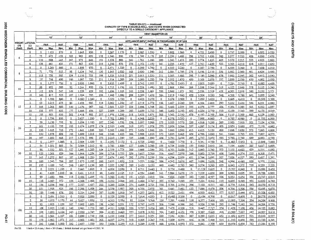
~ ~ ::;; iii (")
0 z en z m z "' 0 r r m 0 (") 0 s: s: m
"' (")
j; r
"' c: ;= 0 z G')
(") 0 0 m
.,, G')
~
HEIGHT
11:2!\
6
8
10
15
20
30
50
100
For SI:
10" 12"
LATERAL
(~t) FAN NAT FAN NAT
Min Max Max Min Max Ma< 0 0 1.121 570 0 }.1:!!5 850
2 75 675 455 103 982 650
4 llO 668 445 147 975 640
6 128 661 435 171 967 630
0 0 1.261 660 0 1.858 970
2 71 770 515 98 l.124 745
5 ll5 758 503 154 1.110 733
8 137 746 490 180 1.097 720
0 0 1.377 720 0 2.036 1.060
2 68 852 560 93 1.244 850
5 112 839 547 149 1.229 829
10 142 817 525 187 1204 795
0 0 1.596 840 0 2.380 l.240
2 63 1.019 675 86 1.495 985
5 105 1.003 660 140 l.476 967
10 135 977 635 177 1.446 936
15 155 9<3 610 202 1.418 905
0 0 1.756 930 0 2.637 1.350
2 59 1.150 755 81 1694 1.100
5 101 1.133 738 135 1.674 1 079
10 130 1.105 710 172 1.641 1.045
15 150 1.078 688 195 1.609 1.018
20 167 1.(152 665 217 1.578 990
0 0 1.077 1.060 0 3.004 1.550
2 54 1.351 865 74 2.004 1.310
5 96 1.332 851 127 1.981 1.289
10 125 1.101 829 164 l.944 1.254
15 143 1.272 807 187 1.908 1.220
20 160 1.243 784 207 1.873 1.185
30 195 1.189 745 ?46 1.807 l.130
0 0 2.231 l.195 0 3.441 1.825
2 41 1.620 1.010 66 2.431 1.513
5 90 l.600 996 ll8 2406 1.495
10 118 1.567 972 154 2.366 1.466
15 136 1.536 948 177 2.327 1.437
20 151 l.505 924 195 2 288 1408
30 183 1.446 876 232 2.214 l.340
0 0 2.491 1.310 0 3.925 2.050
2 30 1.975 1.170 44 3.027 1.820
5 82 1.955 1.159 107 3.002 1.803
10 108 I 923 l 142 142 2.961 1.77"
15 126 1.892 1.124 163 2.920 1.747
20 141 1.861 1.107 181 2.880 1.719
30 170 1.802 1.071 215 ?.803 1.663
50 241 1.688 1.000 292 2.657 1.550
Min
0
138
191
219
0
130
199
231
0
124
192
238
0 114
182
227
257
0
107
174
220
248
273
0
98
164
209
237
260
305
0
86
151
196
222
244
287
0
72
136
180
206
226
265
350
TABLE 504.2{1)- continued CAPACITY OF TYPE B OOUBLE~WALL GAS VENTS WHEN CONNECTED
DIRECTLY TO A SINGLE CATEGORY I APPLIANCE
VENT DIAMETER rrn 14" I 16" 18"
APPLIANCE INPUT RATING IN THOUSANDS OF BTU/H FAN NAT FAN NAT FAN NAT
Max Max Min Max Max Min Max Max 2.267 1.170 0 2.983 1.530 0 3.802 1.960 1346 890 178 1.769 1.170 225 2.250 l.480
1.338 880 242 1.761 1.160 300 2.242 1.475
1.330 870 276 I.753 1.150 341 2.235 1.470
2.571 1.320 0 'l..399 1.740 0 4.333 2.220
1.543 1.020 168 2030 I.340 212 2.584 1.700
1.528 1.010 251 2.013 l.330 311 2.563 1.685
l.514 1.000 289 2.000 1.320 354 2.552 l 670
2.825 1.450 0 ~.742 1.925 0 4.782 2.450
1.713 1.130 161 2.256 1.480 202 2.868 1.890
l.696 1.105 243 2.238 1.461 300 2.849 l 871
1.669 1.080 298 2.209 1.430 364 2.818 1.840
3.323 1.720 0 4.423 2270 0 5 678 2900
2.062 1.35(1 147 2.719 1.770 186 3.467 2.260
2.041 1.327 ?29 2.696 1.748 283 3.442 2.235
2.009 1.280 283 2.659 l.712 346 3.402 2.193
1.976 1.250 318 2.623 1.675 385 3.363 2.150
3.701 1.900 0 4.948 2.520 0 6.376 3.250 'J.343 1.520 139 3.097 2.000 175 3.955 2.570
2320 1.498 219 3.071 1978 270 3 926 2.544
2.282 1.460 273 3.029 1.940 334 3.880 2.500
2.245 1.425 306 2.988 1.910 372 3.835 2.465
'J.210 1.390 335 2.948 1.880 404 3.791 2.430
4.252 2.170 0 5.725 2.920 0 7.420 3.770
2.786 1.800 1'7 3.696 2.380 159 4.734 3.050
2.759 1.775 206 3.666 2.3"i0 252 4.701 3.020
2.716 1.733 259 3.617 2.300 316 4.647 2.CJ70
2.674 1.692 292 3.570 2250 354 4.594 2.920
2.633 1.650 319 3.523 2.200 384 4.542 2.870
2.555 1.585 369 3.433 2130 440 4.442 2.785
4.934 2.550 0 6.711 3.440 0 8.774 4.460
3.409 2.125 113 4.554 2}!A0 141 5.864 3.670
3.380 2.102 191 4520 2.813 234 5.826 3.639
3.332 2.064 243 4.464 2.767 295 5.763 3.585
3.285 2.026 274 4.409 2.721 330 5.701 3.534
3.239 1.987 300 4.356 2 675 361 5.641 3.481
3.150 1.910 347 4.253 2.631 412 5.523 3.431
5.729 2.950 0 7.914 4.050 0 10.485 5.300
4.313 2.550 95 5.834 3.500 120 7.591 4.600
4.282 2.531 172 5.797 3.475 208 7 548 4.566
4.231 2500 223 5.737 3.434 ?68 7 478 4509
4.182 2.4"9 252 5.678 3.392 304 7.409 4.451
4.133 2.438 277 5.619 3.351 330 7.341 4.394
4.037 2.375 319 5.505 3.267 378 7.209 4.279
3.856 2.250 415 5.289 3.100 486 6.956 4.058
1 inch"' 25.4 nun, l foot: 304.8 mm. 1 British thermal unit per hour= 0.2931 W.
20" 22"
FAN NAT FAN
Min Max Max Min Max 0 4.721 2.430 0 5.737
296 2.782 1.R50 360 3.377
390 2.774 l 835 469 3.370
437 2.767 1."20 523 3.363
0 5.387 2.750 0 6.555
278 3.196 2.110 336 3.882
398 3.180 2.090 476 3.863
450 3.163 2.070 537 3.850
0 5.955 3.050 0 7.254
264 3.556 2340 319 4.322
382 3.536 2.318 458 4.301
459 3.504 2.?80 546 4.268
0 7.099 3.620 0 8 665
239 4.304 2.800 290 5.232
355 4.278 2.777 426 5.204
432 4.234 2 739 510 5.159 479 4.192 2.700 564 5.115
0 7.988 4.060 0 9 785
220 4.916 3.200 269 5.983
337 4 885 3.174 403 5.950
413 4.835 3.130 489 5.896
459 4.786 3.090 541 5.844
495 4.737 3.050 585 5.792
0 9.341 4750 0 11.483
199 5.900 3 810 241 7.194
312 5.863 3.783 373 7.155
386 5.803 3.739 456 7.090
431 5.744 3.695 507 7.026
467 5.686 3 650 548 6.964
540 5.574 3 565 635 6.842
0 11.129 5.635 0 13.767
171 7.339 4.630 209 8.980
283 7 295 4.597 336 8.933
355 7.224 4.542 419 8.855
396 7.155 4.511 465 8.779
433 7.086 4.479 506 8.704
494 6.953 4.421 577 8.557
0 13.454 6 700 0 16.817
138 9.577 5.800 169 11.803
245 9.528 5.769 293 11 748
318 9.447 5.717 374 11.658
358 9.367 5.665 418 11.569
387 9.289 5.613 452 11.482
446 9.136 5.509 514 11.310
572 8.841 5.300 659 10.979
NAT
Max Min
2.950 0
2220 426
2.215 555
2.210 618
3 360 0
'J.560 401
2.545 562
2.530 630
3.710 0
2.840 378
2.818 540
2.780 641
4.410 0
3.410 346
3.385 501
3.343 599
3.300 665
4.980 0
3.910 321
3.880 475
3.830 573 3.795 631
3.760 689
5.850 0
4650 285
4.622 439
4.574 535
4.527 590
4.480 639
4.375 739
6.940 0
".695 251
5.654 394
5.585 491
5.546 542
5.506 586
5.444 67?
8.600 0
7.200 204
7.162 341
7.100 436
7.037 487
6.975 523
6.850 592
6.600 752
24"
FAN
Ma< 6.853
4.030
4 023
4.017
7.838
4.634
4.612
4.602
8 682
5.153
5.132
5.099
10.393
6.251
6222
6.175
6.129
11.753
7.154
7.119
7.063
7.007
6.953
13.848
8.617
8.574
8.505
8.437
8.370
8.239
16.694
10.788
10.737
10.652
10.570
10.488
10.328
20.578
14.264
14.204
14.105
14.007
13.910
13.720
13.354
NAT
Max -;520
2.670
2.660
?.650 4.010
'.\.050
3.040
'.030
4.450
3.390
3.371
3.340
5.300
4.080
4.057
4.019
3.980
6.000
4.700
4.662
4.600
4.575
4.550
7.060
5.600
5.552
5.471
5.391
5.310
5.225
8.430
6.860
6.818
6.749
6.710
6.670
6.603
10.300
8.800
8.756
8.683
8.610
8.537
8.391
8.100
(") :c ii: z !!1 en l> z 0 < m
~
:;;! "' r m gi .. ~

i!l i;
"' 0 0
"' :;: iii (")
0 z (/)
z m z ,, 0 r r m 0 (") 0 ;;: ;;: m ,, (") ;;; r ID c: ;= 0 z !;) (")
0 0 m
HEIGHT (HJ
(feet)
6
8
IO
15
20
30
50
100
For SI:
3" 4"
LATERAL FAN NAT FAN NAT (L)
(feet) Min Max Max Min Max Max
0 38 77 45 59 151 85
2 39 51 36 60 96 66
4 NA NA 33 74 92 63
6 NA NA 31 83 89 60
0 37 83 50 58 164 93
2 39 56 39 59 I08 75
5 NA NA 37 77 102 69
8 NA NA 33 90 95 64
0 37 87 53 57 174 99
2 39 61 41 59 ll7 80
5 52 56 39 76 Ill 76
JO NA NA 34 97 100 6S
0 36 93 57 56 190 Ill
2 38 69 47 57 136 93
5 51 63 44 75 128 86
IO NA NA 39 95 ll6 79
15 NA NA NA NA NA 72
0 35 96 60 54 200 ll8
2 37 74 50 56 148 99
5 50 68 47 73 140 94
IO NA NA 41 93 129 86
15 NA NA NA NA NA 80
20 NA NA NA NA NA NA 0 34 99 63 53 211 127
2 37 80 56 55 164 Ill
5 49 74 52 72 157 106
IO NA NA NA 91 144 98
15 NA NA NA 115 l3l NA 20 NA NA NA NA NA NA 30 NA NA NA NA NA NA 0 33 99 66 51 213 133 2 36 84 61 53 181 121
5 48 80 NA 70 174 ll7
IO NA NA NA 89 160 NA 15 NA NA NA 112 148 NA 20 NA NA NA NA NA NA 30 NA NA NA NA NA NA 0 NA NA NA 49 214 NA
2 NA NA NA 51 192 NA
5 N' NA NA 67 186 NA IO N' NA NA 85 175 NA 15 NA NA NA 132 162 NA 20 NA NA NA NA NA NA 30 NA NA NA NA NA NA 50 NA NA NA NA NA NA
TABLE 504.2(2) CAPACITY OF TYPE B DOUBLE-WALL VENTS WITH SINGLE-WALL METAL
CONNECTORS SERVING A SINGLE CATEGORY I APPLIANCE
VENT DIAMETER rm
5" 6" 7" 8"
APPLIANCE INPUT RATING IN THOUSANDS OF BTU/H
FAN NAT FAN NAT FAN NAT FAN NAT
Min Mox Max Min Max Max Min Max Max Min Max Max
85 249 140 126 373 204 165 522 284 211 695 369
85 !56 104 123 231 156 159 320 213 201 423 284
102 152 102 146 225 152 187 313 208 237 416 277
ll4 147 99 163 220 148 207 307 203 263 409 271
83 273 154 123 412 234 161 580 319 206 777 414
83 176 ll9 121 261 179 155 363 246 197 482 321
I07 168 ll4 151 252 171 193 352 235 245 470 311
122 !61 107 175 243 163 223 342 225 280 458 300
82 293 165 120 444 254 158 628 344 202 '44 449
82 193 123 ll9 237 194 153 400 272 193 531 354
I05 185 122 148 277 186 190 388 261 241 518 344
132 171 112 188 261 171 237 369 241 296 497 325
80 325 186 l16 499 233 153 713 388 195 966 523
80 225 149 ll5 337 224 148 473 314 187 631 413
102 216 140 144 326 217 182 459 298 231 616 400
128 201 131 182 308 203 228 438 284 284 592 381
!58 186 124 220 290 192 272 418 269 334 568 367
78 346 201 ll4 537 306 149 772 428 190 1.053 573
78 248 165 113 375 248 144 528 344 182 708 468
mo 239 158 141 363 239 178 514 334 224 692 457
125 223 146 177 344 224 nz 491 316 277 666 437
'55 208 136 216 325 210 264 469 301 325 640 419
186 192 126 254 306 196 309 448 285 374 616 400
76 372 219 110 584 334 144 849 472 184 1.168 647
76 281 183 I09 429 279 139 6IO 392 175 823 533
98 271 173 136 417 271 171 595 382 215 806 521
122 255 168 171 397 257 213 570 367 265 777 501
151 239 157 208 377 242 255 547 349 312 750 481
181 "3 NA 246 357 228 298 524 333 360 723 461
NA NA NA NA NA NA 389 477 305 461 670 426
73 394 230 I05 629 361 138 928 515 176 1.292 704
73 318 205 104 495 312 133 712 443 168 971 613
94 308 198 l3l 482 305 164 696 435 204 953 602
ll8 292 186 162 461 292 203 671 420 253 923 583
145 275 174 199 441 280 244 646 405 299 894 562
176 157 NA 236 420 267 285 622 389 345 866 543
NA NA NA 315 376 NA 373 573 NA 442 809 502
69 403 NA IOO 659 395 131 991 555 166 1.404 765
70 351 NA 98 563 373 125 828 508 158 1.152 698
90 342 NA 125 551 366 156 813 501 194 1.134 688
!13 324 NA 153 532 354 191 789 486 238 1.104 672
138 3IO NA 188 511 343 230 764 473 281 1.075 656
168 295 NA 224 487 NA 270 739 458 325 1.046 639
231 264 NA 301 448 NA 355 685 NA 418 988 NA NA NA NA NA NA NA 540 584 NA 617 866 NA
l inch= 25.4 mm. 1 foot= 304.8 mm. l British thennal unit per hour= 0.2931 W.
I 9" I 10"
FAN NAT FAN
Min Max Mox Min Max
267 894 469 371 1.118
251 541 36S 347 673
295 533 360 409 664
327 526 352 449 656
258 1.002 536 360 1.257
246 617 417 339 768
305 604 404 418 754
344 591 392 470 740
253 1.093 584 351 1.373 242 681 456 332 849
299 667 443 409 834
363 643 423 492 808
244 1259 681 336 1591
232 812 543 319 I.015
287 795 526 392 997
349 768 501 470 966
404 742 484 540 937
238 1.379 750 326 1.751
227 914 611 309 1.146
279 896 596 381 1.126
339 866 570 457 1.092
393 S38 549 526 1.060
448 8IO 526 592 1.028
229 1.542 852 312 1.971
219 I.069 698 296 1.346
269 I.049 684 366 1.324
327 1.017 662 440 1.287
379 985 638 507 1.251
433 955 615 570 1.216
541 895 574 704 1.147
220 J.724 948 295 2.223
209 1.273 811 280 1.615
257 1.252 795 347 1.591
313 J.217 765 418 1.551
363 1.183 736 481 1.512
415 I.150 708 544 1.473
521 1.086 649 674 1.399
207 I.900 1.033 273 2.479
196 I.532 933 259 1.970
240 1.511 921 322 1.945
293 1.477 902 389 1.905
342 I.443 884 447 1.865
391 1.410 864 507 1.825
491 1.343 824 631 1.747
7ll I.205 NA 895 1591
12"
NAT FAN
Max Min Max
569 537 1.639
453 498 979
443 584 971
433 638 962
658 521 1.852 513 486 1.120
500 598 1.104
486 665 1.089
718 507 2.031
559 475 1.242
544 584 1.224
520 688 1.194
838 488 2374
673 457 1.491
657 562 1.469
628 664 1.433
601 750 1.399
927 473 2.631
754 443 1.689
734 547 1.665 702 646 1.626
677 730 1.587
651 808 1.550
1.056 454 2.996
863 424 1.999
846 524 1.971
821 620 1.927
794 702 1.884
76S 780 1.841
720 937 1.759
1.189 428 3.432
1.007 401 2.426
991 496 2.396
963 589 2.347
934 668 2.299
906 741 2.251
848 892 2.159
1.300 395 3.912
1.168 371 3.021
1.153 460 2.990
1.133 547 2.938
l.llO 618 2.888
1.087 690 2.838
1.041 834 2.739
NA 1.138 2547
NAT
Max
849
648
638
627
967
743
730
715
1.057
848
825
788
1.237
983
963
928
894
1.346
1.098 1.074
I.037 1.005
973
I.545
I.308
J.283
1.234
1.205
1.166
J.101
I.818
I.509
1.490
1.455
1.421
i.387
1318
2.042
J.817
I.796
1.763
1.730
I.696
I.627
1.489
:i! ID r m ~ ... N :§
(") :c ~ z m < (/)
)> z 0 < m z Cil

i?l :;i ::; iii 0 0 z (/)
z rn z ~ r r rn c 0 0 s: s: rn :n 0 i> r
"' c: ;= c z Gl 0 0 c rn
.,, Gl ./,.
"'
3" 4"
HEIGHT LATERAL (H) (L)
FAN NAT FAN
(feet) {feet) Min Max Max Min Max
2 NA NA 28 NA NA 6
5 NA NA 25 NA NA
2 NA NA 29 NA NA
8 5 NA NA 26 NA NA
8 NA NA 24 NA NA
2 NA NA 31 NA NA
10 5 NA NA 28 NA NA
10 NA NA 25 NA NA
2 NA NA 35 NA NA
5 NA NA 35 NA NA 15
10 NA NA 28 NA NA
15 NA NA NA NA NA
2 NA NA 38 NA NA
5 NA NA 36 NA NA
20 10 NA NA NA NA NA
15 NA NA NA NA NA
20 NA NA NA NA NA
2 NA NA 41 NA NA
5 NA NA NA NA NA
10 NA NA NA NA NA 30
15 NA NA NA NA NA
20 NA NA NA NA NA
30 NA NA NA NA NA
2 NA NA NA NA NA
5 NA NA NA NA NA
10 NA NA NA NA NA 50
15 NA NA NA NA NA
20 NA NA NA NA NA
30 NA NA NA NA NA
:Minimum Internal Area of Chimney 12 19 (square inches)
Maximum lntern;tl Arca of Chimney 49 88 (square inches)
TABLE 504.2(3) CAPACITY OF MASONRY CHIMNEY FLUE WITH TYPE B DOUBLE-WALL VENT
CONNECTORS SERVING A SINGLE CATEGORY I APPLIANCE
TYPE B DOUBLE-WALL CONNECTOR DIAMETER {D) to be used with chimney areas within the size limits at bottom
5" 6" 7" 8"
APPLIANCE INPUT RATING IN THOUSANDS OF BTU/H
9"
NAT FAN NAT FAN NAT FAN NAT FAN NAT FAN
Max Min Max Max Min Max Max Min Max Max Min Max Max Min Max
52 NA NA 86 NA NA 130 NA NA 180 NA NA 247 NA NA
49 NA NA 82 NA NA 117 NA NA 165 NA NA 231 NA NA
55 NA NA 93 NA NA 145 NA NA 198 NA NA 266 84 590
52 NA NA 88 NA NA 134 NA NA 183 NA NA 247 NA NA
48 NA NA 83 NA NA 127 NA NA 175 NA NA 239 NA NA
61 NA NA 103 NA NA 162 NA NA 221 68 519 298 82 655
57 NA NA 96 NA NA 148 NA NA 204 NA NA 277 124 638
50 NA NA 87 NA NA 139 NA NA 191 NA NA 263 155 610
67 NA NA 114 NA NA 179 53 475 250 64 613 336 77 779
62 NA NA 107 NA NA 164 NA NA 231 99 594 313 118 759
55 NA NA 97 NA NA 153 NA NA 216 126 565 296 148 727
48 NA NA 89 NA NA 141 NA NA 201 NA NA 281 171 698
74 NA NA 124 NA NA 201 51 522 274 61 678 375 73 867
68 NA NA 116 NA NA 184 80 503 254 95 658 350 113 845
60 NA NA 107 NA NA 172 NA NA 237 122 627 332 143 811
NA NA NA 97 NA NA 159 NA NA 220 NA NA 314 165 780
NA NA NA 83 NA NA 148 NA NA 206 NA NA 296 186 750
82 NA NA 137 NA NA 216 47 581 303 57 762 421 68 985
76 NA NA 128 NA NA 198 75 561 281 90 741 393 106 962
67 NA NA 115 NA NA 184 NA NA 263 115 709 373 135 927
NA NA NA 107 NA NA 171 NA NA 243 NA NA 353 156 893
NA NA NA 91 NA NA 159 NA NA 227 NA NA 332 176 860
NA NA NA NA NA NA NA NA NA 188 NA NA 288 NA NA
92 NA NA 161 NA NA 251 NA NA 351 51 840 477 61 1.106
NA NA NA 151 NA NA 230 NA NA 323 83 819 445 98 1.083
NA NA NA 138 NA NA 215 NA NA 304 NA NA 424 126 l.047
NA NA NA 127 NA NA 199 NA NA 282 NA NA 400 146 l.010
NA NA NA NA NA NA 185 NA NA 264 NA NA 376 165 977
NA NA NA NA NA NA NA NA NA NA NA NA 327 NA NA
28 38 50 63 78
137 198 269 352 445
For SI: 1inch=25.4 mm, 1 square inch= 645.16 mm2• 1foot=304.8 mm. 1 British thermal unit per hour= 0.2931 W.
10"
NAT FAN NAT
Max Min Max Max
320 NA NA 401
298 NA NA 376
350 100 728 446
328 149 711 423
318 173 695 410
388 98 810 491
365 146 791 466
347 182 762 444
441 92 968 562
416 139 946 533
394 173 912 567
375 198 880 485
491 87 1.083 627
463 133 1.059 597
440 167 1.022 566
418 191 987 541
397 214 955 513
558 81 1.240 717
526 125 1.216 683
500 l5S 1.176 648
476 181 1.139 621
450 203 1.103 592
416 249 I.035 555
633 72 1.413 812
596 116 I.387 774
567 147 1.347 733
539 170 I.307 702
511 190 1.269 669
468 233 1.196 623
95
550
12"
FAN
Min Max
NA NA
NA NA
139 1.024
201 I.007
231 990
136 1.144
196 1.124
240 1.093
127 1.376
186 1.352
229 1.315
259 1.180
121 1.548
179 1.523
221 1.482
251 1.443
277 1.406
111 1.793
169 1.766
210 1.721
239 1.679
264 1.638
318 1.560
99 2.080
155 2.052
195 2.006
222 1.961
246 1.916
295 I.832
132
792
NAT
Max
581
561
651
640
623
724
712
668
841
828
777
742
953
933
S79
840
807
1.112
1.094
1.025
981
940
877
1.243
1.225
1.147
1.099
1.050
984
0 :I: ~ z rn < (/)
)> z c < rn ~ (/)
~ "' r rn g: .. io :§
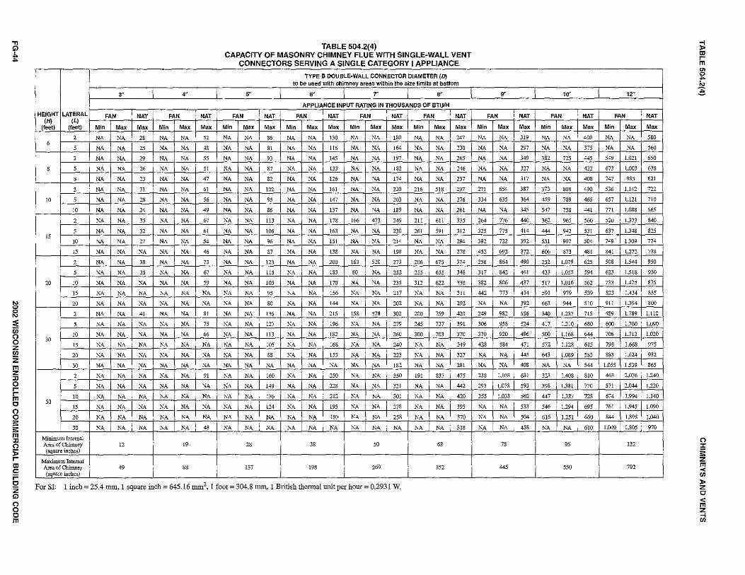
.,, Gl J,. ...
"' 0
r;i ~ "' 0 0 z "' z m z JJ 0 r r m 0 0
~ ;;:; m JJ 0 :;; r ID c: ;= 0 z Gl 0 0 0 m
3" 4"
HEIGHT LATERAL (H) (L)
FAN NAT FAN NAT
(feet) (feet) Min Mox Mox Min Mox Mox
2 NA NA 28 NA NA 52 6
5 NA NA 25 NA NA 48
2 NA NA 29 NA NA 55
8 5 NA NA 26 NA NA 51
8 NA NA 23 NA NA 47
2 NA NA 31 NA NA 61
10 5 NA NA 28 NA NA 56
10 NA NA 24 NA NA 49
2 NA NA 35 NA NA 67
5 NA NA 32 NA NA 61 15
10 NA NA 27 NA NA 54
15 NA NA NA NA NA 46
2 NA NA 38 NA NA 73
5 NA NA 35 NA NA 67
20 10 NA NA NA NA NA 59
15 NA NA NA NA NA NA
20 NA NA NA NA NA NA
2 NA NA 41 NA NA 81
5 NA NA NA NA NA 75
10 NA NA NA NA NA 66 30
15 NA NA NA NA NA NA
20 NA NA NA NA NA NA
30 NA NA NA NA NA NA
2 NA NA NA NA NA 91
5 NA NA NA NA NA NA
10 NA NA NA NA NA NA 50
15 NA NA NA NA NA NA
20 NA NA NA NA NA NA
30 NA NA NA NA NA 41l
Minimum Internal AreaofChimney 12 19 (square inches)
Maximum Internal Area of Chimney 49 88 (square inches)
TABLE 504.2(4) CAPACITY OF MASONRY CHIMNEY FLUE WITH SINGLE-WALL VENT
CONNECTORS SERVING A SINGLE CATEGORY I APPLIANCE
TYPE B DOUBLE-WALL CONNECTOR DIAMETER (D) to be used with chimney areas within the size limits at bottom
5' .. r 8"
APPLIANCE INPUT RATING IN THOUSANDS OF BTUIH
FAN NAT FAN NAT FAN NAT FAN NAT
Min Mox Mox Min Mox Mox Min Mox Mox Min Mox Mox
NA NA 86 NA NA 130 NA NA 180 NA NA 247
NA NA 81 NA NA 116 NA NA 164 NA NA 230
NA NA 93 NA NA 145 NA NA 197 NA NA 265
NA NA 87 NA NA 133 NA NA 182 NA NA 246
NA NA 82 NA NA 126 NA NA 174 NA NA 237
NA NA 102 NA NA 161 NA NA 220 216 518 297
NA NA 95 NA NA 147 NA NA 203 NA NA 276
NA NA 86 NA NA 137 NA NA 189 NA NA 261
NA NA 113 NA NA 178 166 473 249 211 611 335
NA NA 106 NA NA 163 NA NA 230 261 591 312
NA NA 96 NA NA 151 NA NA 214 NA NA 294
NA NA 87 NA NA 138 NA NA 198 NA NA 278
NA NA 123 NA NA 200 163 520 273 206 675 374
NA NA 115 NA NA 183 80 NA 252 255 655 348
NA NA 105 NA NA 170 NA NA 235 312 622 330
NA NA 95 NA NA 156 NA NA 217 NA NA 311
NA NA 80 NA NA 144 NA NA 202 NA NA 292
NA NA 136 NA NA 215 158 578 302 200 759 420
NA NA 127 NA NA 196 NA NA 279 245 737 391
NA NA 113 NA NA 182 NA NA 260 300 703 370
NA NA 105 NA NA 168 NA NA 240 NA NA 349
NA NA SS NA NA 155 NA NA 223 NA NA 327
NA NA NA NA NA NA NA NA 182 NA NA 281
NA NA 160 NA NA 250 NA NA 350 191 837 475
NA NA 149 NA NA 228 NA NA 321 NA NA 442
NA NA 136 NA NA 212 NA NA 301 NA NA 420
NA NA 124 NA NA 195 NA NA 278 NA NA 395
NA NA NA NA NA 180 NA NA 258 NA NA 370
NA NA NA NA NA NA NA NA NA NA NA 318
28 38 50 63
137 198 269 352
For SI: 1 inch= 25.4 mm, 1 square inch= 645.16 mm2• 1 foot= 304.8 mm. 1 British thermal unit per hour= 0.2931 W.
.. 10"
FAN NAT FAN
Min Mox Mox Min Mox
NA NA 319 NA NA
NA NA 297 NA NA
NA NA 349 382 725
NA NA 327 NA NA
NA NA 317 NA NA
271 654 387 373 808
334 635 364 459 789
NA NA 345 547 758
264 776 440 362 965
325 775 414 444 942
392 722 392 531 907
452 692 372 606 873
258 864 490 252 1.079
317 842 461 433 1.055
382 806 437 517 1.016
442 773 414 591 979
NA NA 392 663 944
249 982 556 340 1.237
306 958 524 417 I.210
370 920 496 500 1J68
428 884 471 572 1.128
NA NA 445 643 1.089
NA NA 408 NA NA
238 I.103 631 323 1.408
293 J.078 593 398 1.381
355 I.038 562 447 1.337
NA NA 533 546 1.294
NA NA 504 616 l.251
NA NA 458 NA NA
78 95
445 550
12'"
NAT FAN
Mox Min Mox
400 NA NA
375 NA NA
445 549 1.021
422 673 1.003
408 747 985
490 536 1.142
465 657 1.121
441 771 1.088
560 520 1373
531 637 13413
504 749 1309
481 841 1.272
625 508 1.544
594 623 1.518
562 733 1.475
539 823 I.434
510 911 1.394
715 489 L789
680 600 1.760
644 708 1.713
615 798 1.668
585 883 1.624
544 1.055 1.539
810 463 2.076
770 571 2,044
728 674 1.994
695 761 1.945
660 844 1.898
610 1.009 1.805
132
792
NAT
Mox
580
560
650
638
621
722
710
665
840
825
774
738
950
930
875
835
800
I.110
1.090
1.020
975
932
865
1.240
1.220
1.140
I.090
I.040
970
i! ID r m
"' 2 io ~
0 :r § z m ~ l> z 0 < m
~

CHIMNEYS AND VENTS TABLE 504.2(5)
TABLE 504.2(5) CAPACITY OF SINGLE-WALL METAL PIPE OR TYPE B ASBESTOS CEMENT VENTS
SERVING A SINGLE DRAFT HOOD EQUIPPED APPLIANCE
VENT DIAMETER (0)
HEIGHT LATERAL 3" 4" 5" 6" 7" 6" 10'' 12" (If) (L)
(feet) (feet) MAXIMUM APPLIANCE INPUT RATING IN THOUSANDS OF BTU/H
0 39 70 116 170 232 312 500 750
6 2 31 55 94 141 194 260 415 620
5 28 51 88 128 177 242 390 600
0 42 76 126 185 252 340 542 815
2 32 61 102 154 210 284 451 680 8
5 29 56 95 141 194 264 430 648
10 24 49 86 131 180 250 406 625
0 45 84 138 202 279 372 606 912
2 35 67 111 168 233 311 505 760
10 5 32 61 104 153 215 289 480 724
10 27 54 94 143 200 274 455 700
15 NA 46 84 130 186 258 432 666
0 49 91 151 223 312 420 684 1,040
2 39 72 122 186 260 350 570 865
5 35 67 110 170 240 325 540 825 15
10 30 58 103 158 223 308 514 795
15 NA 50 93 144 207 291 488 760
20 NA NA 82 132 195 273 466 726
0 53 101 163 252 342 470 770 1,190
2 42 80 136 210 286 392 641 990
5 38 74 123 192 264 364 610 945 20
10 32 65 115 178 246 345 571 910
15 NA 55 104 163 228 326 550 870
20 NA NA 91 149 214 306 525 832
0 56 108 183 276 384 529 878 1,370
2 44 84 148 230 320 441 730 1,140
5 NA 78 137 210 296 410 694 1,080
30 10 NA 68 125 196 274 388 656 1,050
15 NA NA 113 177 258 366 625 1,000
20 NA NA 99 163 240 344 596 960
30 NA NA NA NA 192 295 540 890
0 NA 120 210 310 443 590 980 1,550
2 NA 95 171 260 370 492 820 1,290
5 NA NA 159 234 342 474 780 1,230
50 10 NA NA 146 221 318 456 730 1,190
15 NA NA NA 200 292 407 705 1,130
20 NA NA NA 185 276 384 670 1,080
30 NA NA NA NA 222 330 605 1,010
For SI: l inch:::: 25.4 mm, l foot= 304.8 nun, 1 British the1mal unit per hour= 0.2931 W.
2002 WISCONSIN ENROLLED COMMERCIAL BUILDING CODE FG-45
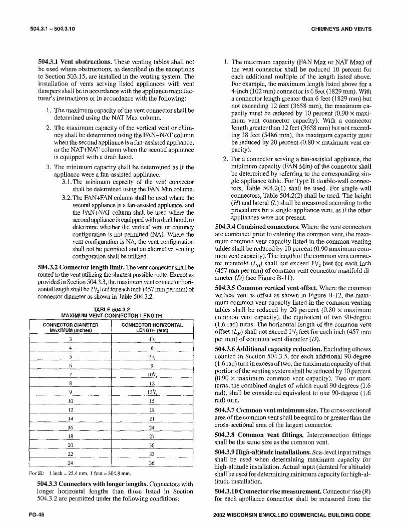
504.3.1 - 504.3.10
504.3.1 Vent obstructions. These venting tables shall not be used where obstructions, as described in the exceptions to Section 503.15, are installed in the venting system. The installation of vents serving listed appliances with vent dampers shall be in accordance with the appliance manufacturer's instructions or in accordance with the following:
1. The maximum capacity of the vent connector shall be determined using the NAT Max column.
2. The 1naximum capacity of the vertical vent or chimney shall be determined using the FAN+NAT column when the second appliance is a fan-assisted appliance, or the NAT +NAT column when the second appliance is equipped with a draft hood.
3. The minimum capacity shall be determined as if the appliance were a fan-assisted appliance.
3. I. The minimum capacity of the vent connector shall be detennined using the FAN Min column.
3.2. The FAN+FAN column shall be used where the second appliance is a fan-assisted appliance, and the FAN+NAT column shall be used where the second appliance is equipped with a draft hood, to determine whether the ve1tical vent or chimney configuration is not permitted (NA). Where the vent configuration is NA, the vent configuration shall not be permitted and an alternative venting configuration shall be utilized.
504.3.2 Connector length limit. The vent connector shall be routed to the vent utilizing the shmtest possible route. Except as provided in Section 504.3.3, the inaxhnum vent connector holizontal length shall be 11/ 2 feetfor each inch (457 mm per mm) of connector dian1eter as shown in Table 504.3.2.
TABLE 504.3.2 MAXIMUM VENT CONNECTOR LENGTH
CONNECTOR DIAMETER CONNECTOR HORIZONTAL MAXIMUM (Inches} LENGTH (feet)
3 4'1
4 6
5 7'! 6 9
7 101/
8 12
9 131/,
10 15
12 18
14 21
16 24
18 27
20 30
22 33
24 36
For SI: 1 inch= 25.4 n1m, 1 foot= 304.8 mm,
504.3.3 Connectors with longer lengths. Connectors with longer horizontal lengths than those listed in Section 504.3.2 are permitted under the following conditions:
FG-46
CHIMNEYS AND VENTS
1. The maximum capacity (FAN Max or NAT Max) of the vent connector shall be reduced 10 percent for each additional multiple of the length listed above. For example, the maximum length listed above for a 4-inch (102 mm) connectoris 6 feet (1829 mm). With a connector length greater than 6 feet (1829 mm) but not exceeding 12 feet (3658 mm), the maximum capacity must be reduced by 10 percent (0.90 x maximum vent connector capacity). With a connector length greater than 12 feet (3658 mm) but not exceeding 18 feet (5486 mm), the maximum capacity must be reduced by 20 percent (0.80 x maximum vent capacity).
2. For a connector serving a fan-assisted appliance, the minimum capacity (FAN Min) of the connector shall be determined by refening to the conesponding single appliance table. For Type B double-wall connectors, Table 504.2(1) shall be used. For single-wall connectors, Table 504.2(2) shall be used. The height (H) and lateral (L) shall be measured according to the procedures for a single-appliance vent, as if the other appliances were not present.
504.3.4 Combined connectors. Where the vent connectors are combined p1ior to entering the common vent, the maximum common vent capacity listed in the common venting tables shall be reduced by 10 percent (0.90 maximum common vent capacity). The length of the common vent connector manifold (LM) shall not exceed 11/ 2 feet for each inch ( 457 mm per mm) of common vent connector manifold diameter (D) (see Figure B-11).
504.3.5 Common vertical vent offset, Where the common vertical vent is offset as shown in Figure B-12, the maximu1n common vent capacity listed in the co1n1non venting tables shall be reduced by 20 percent (0.80 x maximum conunon vent capacity), the equivalent of two 90-degree (1.6 rad) turns. The horizontal length of the common vent offset (L"') shall not exceed 11/ 2 feet for each inch ( 457 mm per mm) of common vent diameter (D).
504.3.6 Additional capacity reduction. Excluding elbows counted in Section 504.3.5, for each additional 90-degree (1.6 rad) turn in excess of two, the maximum capacity of that portion of the venting system shall be reduced by 10 percent (0.90 x maximum common vent capacity). Two or more turns, the combined angles of which equal 90 degrees (1.6 rad), shall be considered equivalent to one 90-degree ( 1.6 rad) turn.
504.3.7 Common vent minimum size. The cross-sectional area of the common vent shall be equal to or greater than the cross-sectional area of the largest connector.
504.3.8 Common vent fittings. Interconnection fittings shall be the sa1ne size as the common vent.
504.3.9 High-altitude installations. Sea-level input ratings shall be used when determining maximum capacity for high-altitude installation. Actual input ( derated for altitude) shall be used fordetermining minimum capacity for high-altitude installation.
504.3.10 Connector rise measurement. Connector rise (R) for each appliance connector shall be measured from the
2002 WISCONSIN ENROLLED COMMERCIAL BUILDING CODE

CHIMNEYS AND VENTS
draft hood outlet or flue collar to the centerline where the vent gas streams come together.
504.3.11 Vent height measurement. For multiple units of equipment all located on one floor, available total height (H) shall be measured from the highest draft hood outlet or flue collar up to the level of the outlet of the common vent.
504.3.12 Multistory height measurement. For multistory installations, available total height (H) for each segment of the system shall be the vertical distance between the highest draft hood outlet or flue collar entering that segment and the centerline of the next higherinterconnection tee (see Figure B-13).
504.3.13 Multistory lowest portion sizing. The size of the lowest corn1ector and of the vertical vent leading to the lowest interconnection of a multisto1y system shall be in accordance with Table 504.2(1) or 504.2(2) for available total height (H) up to the lowest interconnection (see Figure B-14).
504.3.14 Multistory common vent offsets. Where used in multistory systems, vertical common vents shall be Type B double wall and shall be installed with a listed vent cap. A multistmy common vertical vent shall be pe1mitted to have a single offset, provided all of the following requirements are met:
I. The offset angle does not exceed 45 degrees (0. 79 rad).
2. Thehorizontallengthoftheoffsetdoesnotexceed 11/ 2
feet for each inch ( 457 mm per mm) of common vent diameterof the segment in which the offset is located.
3. Forthe segment of the common vertical vent containing the offset, the common vent capacity listed in the common venting tables is reduced by 20 percent (0.80 x maximum common vent capacity).
4. A multistmy common vent shall not be reduced in size above the offset.
504.3.15 Vertical vent maximum size. Where two or more appliances are connected to a vertical vent or chimney, the flow area of the largest section of vertical vent or chimney shall not exceed seven times the smallest listed appliance categorized vent areas, flue collar area, or draft hood outlet area unless designed in accordance with approved engineering methods.
504.3.16 Multiple input rate appliances. For appliances with more than one input rate, the minimum vent connector capacity (FAN Min) determined from the tables shall be less than the lowest appliance input rating, and the maximum vent connector capacity (FAN Max or NAT Max) determined from the tables shall be greater than the highest appliance input rating.
504.3.17 Liner system sizing. Listed, corrugated metallic chimney liner systems in masonry chimneys shall be sized by using Table 504.3(1) or 504.3(2) for Type B vents, with the maximum capacity reduced by 20 percent (0.80 x maximum capacity) and the minimum capacity as shown in Table 504.3(1) or 504.3(2). Corrugated metallic liner systems installed with bends or offsets shall have their maximum capacity further reduced in accordance with Sections 504.3.5 and 504.3.6.
2002 WISCONSIN ENROLLED COMMERCIAL BUILDING CODE
504.3.11 - 504.3.20
504.3.18 Chimney and vent location. Tables 504.3(1 ), 504.3(2), 504.3(3), 504.3(4), and 504.3(5) shall be used for chimneys and vents not exposed to the outdoors below the roof line. A Type B vent or listed chimney lining system passing through an unused masonry chimney flue shall not be considered to be exposed to the outdoors. Tables 504.3(7) and 504.3(8) shall be used for clay-tile-lined exterior masomy chimneys, provided all of the following conditions are met:
1. Vent connector is Type B double-wall.
2. At least one appliance is draft hood equipped.
3. The combined appliance input rating is less than the maximum capacity given by Table 504.3(7a) for NAT+NAT or Table 504.3(8a) for FAN+ NAT.
4. The input rating of each space-heating appliance is greater than the minimum input rating given by Table 504.3(7b) for NAT+NAT or Table 504.3(8b) for FAN+NAT.
5. The vent connector sizing is in accordance with Table 504.3(3).
Where these conditions cannot be met, an alternative venting design shall be used, such as a listed chimney lining system.
Exception: The installation of vents serving listed appliances shall be pennitted to be in accordance with the appliance inanufacturer's instructions and the tenns of the listing.
504.3.19 Connector maximum size. Vent connectors shall not be increased in size n1ore than two sizes greater than the listed appliance categorized vent diameter, flue collar diameter, or draft hood outlet diameter. Vent connectors for draft hood-equipped appliances shall not be smaller than the draft hood outlet diameter. Where a vent connector size(s) determined from the tables for a fan-assisted appliance(s) is smaller than the flue collar diameter, the smaller size(s) shall be pennitted to be used provided all of the following conditions are met:
1. Vent connectors for fan-assisted appliance flue collars 12 inches (305 mm) in diameter or smaller are not reduced by more than one table size [e.g., 12 inches to 10 inches (305 mm to 254 mnl) is a one-size reduction] and those larger than 12 inches (305 mm) in diameter are not reduced more than two table sizes [e.g., 24 inches to 20 inches (610 mm to 508 mm) is a twosize reduction].
2. The fan-assisted appliance(s) is common vented with a draft-hood-equipped appliances(s).
504.3.20 Component commingling. All combinations of pipe sizes, single-wall, and double-wall metal pipe shall be allowed within any connector run(s) or within the cotnmon vent, provided all of the appropriate tables petmit all of the desired sizes and types of pipe, as if they were used for the entire length of the subject connector or vent. Where singlewall and Type B double-wall metal pipes are used for vent connectors, the comtnon vent must be sized using Table 504.3(2) or 504.3(4), as appropriate.
FG-47
504.3.21 - 506.3
504.3.21 Multiple sizes permitted. Where a table permits more than one diameter of pipe to be used for a connector or vent, all the permitted sizes shall be permitted to be used.
504.3.22 Table interpolation. Interpolation shall be permitted in calculating capacities for vent dimensions that fall between table entries (see Appendix B, Example 3).
504.3.23 Extrapolation prohibited. Extrapolation beyond the table entries shall not be permitted.
504.3.24 Engineering calculations. For vent heights less than 6 feet (1829 mm) and greater than shown in the tables, engineering methods shall be used to calculate vent capacities.
SECTION 505 (IFGC) DIRECT-VENT, INTEGRAL VENT,
MECHANICAL VENT AND VENTILATION/EXHAUST HOOD VENTING
505.1 The installation of direct-vent and integral vent appliances shall be in accordance with Section 503. Mechanical venting systems and exhaust hood venting systems shall be designed and installed in accordance with Section 503.
SECTION 506 (IFGC) FACTORY-BUILT CHIMNEYS
506.1 Building heating appliances. Factory-built chimneys for building heating appliances producing flue gases having a temperature not greater than l,000°F (538°C), measured at the entrance to the chimney, shall be listed and labeled in accordance with UL 103 and shall be installed and terminated in accordance with the 1nanufacturer's installation instructions.
506.2 Snpport. Where factory-built chimneys are supported by structural members, such as joists and rafters, such members shall be designed to support the additional load.
506.3 Medium-heat appliances. Factory-built chimneys for medium-heat appliances producing flue gases having a temperature above l,000°F (538°C), measured at the entrance to the chimney, shall be listed and labeled in accordance with UL 959 and shall be installed and terminated in accordance with the manufacturer's installation instructions.
FG-48
CHIMNEYS AND VENTS
2002 WISCONSIN ENROLLED COMMERCIAL BUILDING CODE

CHIMNEYS AND VENTS
VENT CONNECTOR CAPACITY
3"
VENT CONNECTOR
TABLE 504.3(1) CAPACITY OF TYPE B DOUBLE-WALL VENTS WITH TYPE B DOUBLE-WALL
CONNECTORS SERVING TWO OR MORE CATEGORY I APPLIANCES
TYPE 8 DOUBLE-WALL VENT AND CONNECTOR DIAMETER (D)
4" I 5" I 6" 7" I 8"
APPLIANCE INPUT RATING LIMITS IN THOUSANDS OF BTU/H
9"
HEIGHT RISE FAN (H) (R)
NAT FAN NAT FAN NAT FAN NAT FAN NAT FAN NAT FAN
(feet) (feet) Ml" M" M" Ml" Mox M" Ml" M" Mox Min Mox M" Ml" M" M" Ml" M" M" Ml" M"
1 22 37 26 35 66 46 46 106 72 58 164 104 77 225 142 92 296 185 109 376
6 2 23 41 31 37 75 55 48 121 86 60 183 124 79 253 168 95 333 220 112 424
3 24 44 35 38 81 62 49 132 96 62 199 139 82 275 189 97 363 248 114 463
1 22 40 27 35 72 48 49 114 76 64 176 109 84 243 148 100 320 194 118 408
8 2 23 44 32 36 80 57 51 128 90 66 195 129 86 269 175 103 356 230 121 454
3 24 47 36 37 87 64 53 139 101 67 210 145 88 290 198 105 384 258 123 492
1 22 43 28 34 78 50 49 123 78 65 189 113 89 257 154 106 341 200 125 436
10 2 23 47 33 36 86 59 51 136 93 67 206 134 91 282 182 109 374 238 128 479
3 24 50 37 37 92 67 52 146 104 69 220 150 94 303 205 111 402 268 131 515
1 21 50 30 33 89 53 47 142 83 64 220 120 88 298 163 110 389 214 134 493
15 2 22 53 35 35 96 63 49 153 99 66 235 142 91 320 193 112 419 253 137 532
3 24 55 40 36 102 71 51 163 111 68 248 160 93 339 218 115 445 286 140 565
1 21 54 31 33 99 56 46 157 87 62 246 125 86 334 171 107 436 224 131 552
20 2 22 57 37 34 105 66 48 167 104 64 259 149 89 354 202 110 463 265 134 587
3 23 60 42 35 110 74 50 176 116 66 271 168 91 371 228 l13 486 300 137 618
1 20 62 33 31 113 59 45 181 93 60 288 134 83 391 182 103 512 238 125 649
30 2 21 64 39 33 118 70 47 190 110 62 299 158 85 408 215 105 535 282 129 679
3 22 66 44 34 123 79 48 198 124 64 309 178 88 423 242 108 555 317 132 706
1 19 71 36 30 133 64 43 216 101 57 349 145 78 477 197 97 627 257 120 797
50 2 21 73 43 32 137 76 45 223 119 59 358 172 81 490 234 100 645 306 123 820
3 22 75 48 33 141 86 46 229 134 61 366 194 83 502 263 103 661 343 126 842
1 18 82 37 28 158 66 40 262 104 53 442 150 73 611 204 91 810 266 112 1,038
100 2 19 83 44 30 161 79 42 267 123 55 447 178 75 619 242 94 822 316 115 1,054
3 20 84 50 31 163 89 44 272 138 57 452 109 78 627 272 97 834 355 118 1,069
COMMON VENT CAPACITY
TYPE B DOUBLE-WALL COMMON VENT DIAMETER (D)
4" 5" 6" 7" 8" 9"
VENT COMBINED APPLIANCE INPUT RATING IN THOUSANDS OF BTU/H HEIGHT
(H) FAN FAN NAT FAN FAN NAT FAN FAN NAT FAN FAN NAT FAN FAN NAT FAN FAN NAT (feet) +FAN +NAT +NAT +FAN +NAT +NAT +FAN +NAT +NAT +FAN +NAT +NAT +FAN +NAT +NAT +FAN +NAT +NAT
6 92 81 65 140 116 103 204 161 147 309 248 200 404 314 260 547 434 335
8 101 90 73 155 129 114 224 178 163 339 275 223 444 348 290 602 480 378
10 110 97 79 169 141 124 243 194 178 367 299 242 477 377 315 649 522 405
15 125 li2 91 195 164 144 283 228 206 427 352 280 556 444 365 753 612 465
20 136 123 102 215 183 160 314 255 229 475 394 310 62! 499 405 842 688 523
30 152 138 118 244 210 185 361 297 266 547 459 360 720 585 470 979 808 605
50 167 153 134 279 244 214 421 353 310 641 547 423 854 706 550 l,164 977 705
100 175 163 NA 311 277 NA 489 421 NA 751 658 479 l,025 873 625 l,408 1,215 800
(continued)
2002 WISCONSIN ENROLLED COMMERCIAL BUILDING CODE
TABLE 504.3(1)
10"
NAT FAN NAT
Mox Ml" Mox Mox
237 128 466 289
282 131 526 345
317 134 575 386
248 138 507 303
294 141 564 358
330 143 612 402
257 146 542 314
305 149 596 372
342 152 642 417
273 162 609 333
323 165 658 394
365 167 700 444
285 158 681 347
339 161 725 414
383 164 764 466
305 151 802 372
360 155 840 439
405 158 874 494
330 144 984 403
392 148 l,014 478
441 151 1,043 538
341 135 l,285 417
405 139 1,306 494
455 142 1,327 555
10"
FAN FAN NAT +FAN +NAT +NAT
672 520 410
740 577 465
800 627 495
924 733 565
l.035 826 640
l,209 975 740
1,451 l,188 860
1,784 1,502 975
FG·49

TABLE 504.3(1) CHIMNEYS AND VENTS
TABLE 504.3(1) - continued CAPACITY OF TYPE B DOUBLE-WALL VENTS WITH TYPE B DOUBLE-WALL
CONNECTORS SERVING TWO OR MORE CATEGORY I APPLIANCES VENT CONNECTOR CAPACITY
TYPE 8 DOUBLE-WALL VENT AND DIAMETER (D)
12" 14" 16" 18" 20" 22"
VENT CONNECTOR APPLIANCE INPUT RATING LIMITS IN THOUSANDS OF BTU/H
HEIGHT RISE (H) (R)
FAN NAT FAN NAT FAN NAT FAN NAT FAN NAT FAN NAT
(feet) {feet) Min M" M" Mio M" M" Mio M" M" Min M" M" Min M" M" Mio M" M"
2 174 764 496 223 1,046 653 281 l,371 853 J46 1,772 1,080 NA NA NA NA NA NA
6 4 180 897 616 2JO 1,231 827 287 1,617 1,081 J52 2,069 1,370 NA NA NA NA NA NA
6 NA NA NA NA NA NA NA NA NA NA NA NA NA NA NA NA NA NA
2 186 822 516 2J8 1,126 696 298 1,478 910 J65 1,920 1,150 NA NA NA NA NA NA
8 4 192 952 644 244 1,307 884 305 1,719 1,150 372 2,211 1,460 471 2,737 1,800 560 3,319 2,180
6 198 l,050 772 252 1,445 1,072 31J 1,902 1,390 J80 2,434 1,770 478 3,018 2,180 568 3,665 2,640
2 196 870 5J6 249 1,195 7JO Jl l 1,570 955 J79 2,049 1,205 NA NA NA NA NA NA
10 4 201 997 664 256 1,371 924 J18 1,804 1,205 J87 2,332 1,535 486 2,887 1,890 581 3,502 2,280
6 207 l,095 792 26J 1,509 1,l18 325 1,989 1,455 J95 2,556 1,865 494 3,169 2,290 589 3,849 2,760
2 214 967 568 272 1,334 790 J36 l,760 l,030 408 2,317 1,305 NA NA NA NA NA NA
15 4 221 l,085 712 279 1,499 1,006 J44 1,978 1,320 416 2,579 1,665 52J 3,197 2,060 624 3,881 2,490
6 228 1,181 856 286 1,632 1,222 351 2,157 1,610 424 2,796 2,025 5JJ 3,470 2,510 6J4 4,216 3,030
2 223 1,051 596 291 1,443 840 J57 1,91 ! 1,095 4JO 2,533 1,385 NA NA NA NA NA NA
20 4 2JO 1,162 748 298 1,597 1,064 J65 2,116 1,395 4J8 2,778 l,765 554 3,447 2,180 661 4,190 2,630
6 237 1,253 900 J07 1,726 1,288 37J 2,287 1,695 450 2,984 2,145 567 3,708 2,650 671 4,511 3,190
2 216 1,217 6J2 286 !,664 910 367 2,183 1,190 461 2,891 1,540 NA NA NA NA NA NA
JO 4 22J 1,316 792 294 1,802 1,160 376 2,366 1,510 474 3,110 1,920 619 3,840 2,365 728 4,861 2,860
6 231 1,400 952 JOJ 1,920 1,410 J84 2,524 1,830 485 3,299 2,340 6J2 4,080 2,875 741 4,976 3,480
2 206 1,479 689 273 2,023 [,007 J50 2,659 1,315 4J5 3,548 1,665 NA NA NA NA NA NA
50 4 213 1,561 860 281 2,139 1,291 359 2,814 1,685 447 3,730 2,135 580 4,601 2,633 709 5,569 3,185
6 221 1,631 1,031 290 2,242 1,575 J69 2,951 2,055 461 3,893 2,605 594 4,808 3,208 724 5,826 3,885
2 192 1,923 712 254 2,644 1,050 J26 3,490 1,370 402 4,707 1,740 NA NA NA NA NA NA
100 4 200 1,984 888 26J 2,731 1,346 JJ6 3,606 1,760 414 4,842 2,220 523 5,982 2,750 639 7,254 3,330
6 208 2,035 l,064 272 2,811 1,642 J46 3,714 2,150 426 4,968 2,700 5J9 6,143 3,350 654 7,453 4,070
COMMON VENT CAPACITY
TYPE B DOUBLE·WALL COMMON VENT DIAMETER (D)
12" 14" 16" 18" 20" 22"
VENT HEIGHT
COMBINED APPLIANCE INPUT RATING IN THOUSANDS OF BTU/H
(H) FAN FAN NAT FAN FAN NAT FAN FAN NAT FAN FAN NAT FAN FAN NAT FAN FAN NAT (feet) +FAN +NAT +NAT +FAN <NAT +NAT +FAN +NAT +NAT +FAN +NAT +NAT +FAN +NAT +NAT +FAN +NAT +NAT
6 900 696 588 1,284 990 815 1,735 1,336 1,065 2,253 1,732 1,345 2,838 2,180 1,660 3,488 2,677 1970
8 994 773 652 1,423 1,!03 912 1,927 1,491 1,190 2,507 1,936 1,510 3,162 2,439 1,860 3,890 2,998 2,200
10 1,076 841 712 1,542 1,200 995 2,093 1,625 l,300 2,727 2,113 1645 3,444 2,665 2,030 4,241 3,278 2,400
15 1,247 986 825 1,794 1,410 1,158 2,440 1,910 1,510 3,184 2,484 1,910 4,026 3,133 2,360 4,971 3,862 2,790
20 1,405 1,116 916 2,006 1,588 l,290 2,722 2,147 1,690 3,561 2,798 2,140 4,548 3,552 2,640 5,573 4,352 3,120
JO 1,658 1,327 1,025 2,373 1,892 1,525 3,220 2,558 l,990 4,197 3,326 2,520 5,303 4,193 3,110 6,539 5,157 3,680
50 2,024 1,640 1,280 2,911 2,347 1,863 3,964 3,183 2,430 5,184 4,149 3,075 6,567 5,240 3,800 8,116 6,458 4,500
24"
FAN
Min M"
NA NA
NA NA
NA NA
NA NA
662 3,957
669 4,373
NA NA
686 4,175
694 4,593
NA NA
734 4,631
74J 5,035
NA NA
772 5,005
785 5,392
NA NA
847 5,606
860 5,961
NA NA
851 6,633
867 6,943
NA NA
769 8,650
786 8,892
24"
FAN FAN +FAN +NAT
4,206 3,226
4,695 3,616
5,123 3,957
6,016 4,670
6,749 5,261
7,940 6,247
9,837 7,813
100 2,569 2,131 1,670 3,732 3,076 2,450 5,125 4,202 3,200 6,749 5,509 4,050 8,597 6,986 5,000 10,681 8,648 5,920 13,004 10,499
For SI: 1inch=25.4 inm, 1foot=304.8 1nm, 1 British thermal unit per hour= 0.2931 W,
NAT
M"
NA
NA
NA
NA
2,590
3,130
NA
2,710
3,270
NA
2,960
3,600
NA
3,130
3,790
NA
3,410
4,150
NA
3,790
4,620
NA
3,950
4,810
NAT +NAT
2,390
2,680
2,920
3,400
3,800
4,480
5,475
7,200
FG·50 2002 WISCONSIN ENROLLED COMMERCIAL BUILDING CODE
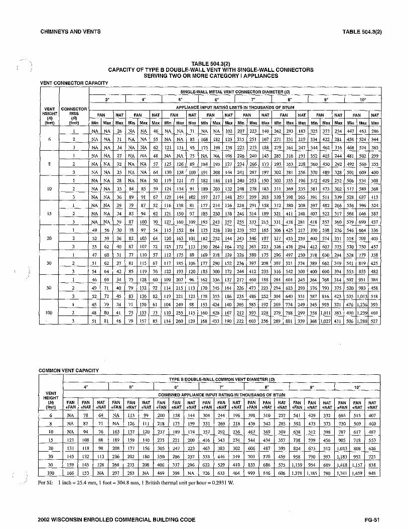
CHIMNEYS AND VENTS
VENT CONNECTOR CAPACITY
TABLE 504.3(2) CAPACITY OF TYPE B DOUBLE-WALL VENT WITH SINGLE-WALL CONNECTORS
SERVING TWO OR MORE CATEGORY I APPLIANCES
SINGLE-WALL METAL VENT CONNECTOR DIAMETER (D)
3" 4" 5" 6" 7" , .. VENT CONNECTOR APPLIANCE. INPUT RATING LIMITS IN THOUSANDS OF BTU/H
9"
HEIGHT RISE FAN NAT FAN NAT FAN NAT FAN NAT FAN NAT FAN NAT FAN (H) (R)
(feet) (feetl Ml" Mox Max Ml" Mox Mox Ml" Mox Max Min Mox Mox Min Mox Mox Ml" Mox Max Min Mox
1 NA NA 26 NA NA 46 NA NA 71 NA NA 102 207 223 140 262 293 183 325 373
6 2 NA NA 31 NA NA 55 NA NA 85 168 182 123 215 251 167 271 331 219 334 422
3 NA NA 34 NA NA 62 121 131 95 175 198 138 222 273 188 279 361 247 344 462
1 NA NA 27 NA NA 48 NA NA 75 NA NA 106 226 240 145 285 316 191 352 403
8 2 NA NA 32 NA NA 57 125 126 89 184 193 127 234 266 173 293 353 228 360 450
3 NA NA 35 NA NA 64 130 138 100 191 208 144 241 287 197 302 381 256 370 489
1 NA NA 28 NA NA 50 119 121 77 182 186 110 240 253 150 302 335 196 372 429
10 2 NA NA 33 84 85 59 124 134 91 189 203 132 248 278 183 311 369 235 381 473
3 NA NA 36 89 91 67 129 144 102 197 217 148 257 299 203 320 398 265 391 511
1 NA NA 29 79 87 52 116 138 81 177 214 116 238 291 158 312 380 208 397 482
15 2 NA NA 34 83 94 62 121 150 97 185 230 138 246 314 189 321 411 248 407 522
3 NA NA 39 87 100 70 127 160 109 193 243 157 255 333 215 331 438 281 418 557
1 49 56 30 78 97 54 115 152 84 175 238 120 233 325 165 306 425 217 390 538
20 2 52 59 36 82 103 64 120 163 101 182 252 144 243 346 197 317 453 259 400 574
3 55 62 40 87 107 72 125 172 II3 190 264 164 252 363 223 326 476 294 412 607
1 47 60 31 77 IIO 57 112 175 89 169 278 129 226 380 175 296 497 230 378 630
30 2 51 62 37 81 115 67 ll7 185 106 177 290 152 236 397 208 307 521 274 389 662
3 54 64 42 85 II9 76 122 193 120 185 300 172 244 412 235 316 542 309 400 690
I 46 69 34 75 128 60 109 207 96 162 336 137 217 460 188 284 604 245 364 768
50 2 49 71 40 79 132 72 114 215 113 170 345 164 226 473 223 294 623 293 376 793
3 52 72 45 83 136 82 119 221 123 178 353 186 235 486 252 304 640 331 387 816
I 45 79 34 71 150 61 104 249 98 153 424 140 205 585 192 269 774 249 345 993
100 2 48 80 4I 75 153 73 IIO 255 115 160 428 167 212 593 228 279 788 299 358 1,0ll
3 51 8I 46 79 157 85 114 260 129 168 433 190 222 603 256 289 801 339 368 1,027
COMMON VENT CAPACITY
TYPE B DOUBLE-WALL COMMON VENT DIAMETER (D)
4" 5" 6" 7" , .. 9"
VENT COMBINED APPLIANCE 1NPUT RATING IN THOUSANDS OF BTU/H HEIGHT
(H) FAN FAN NAT FAN FAN NAT FAN FAN NAT FAN FAN NAT FAN FAN NAT FAN FAN NAT (feet) +FAN +NAT +NAT +FAN +NAT +NAT +FAN +NAT +NAT +FAN +NAT +NAT +FAN +NAT +NAT +FAN +NAT +NAT
6 NA 78 64 NA ll3 99 200 158 144 304 244 196 398 310 257 541 429 332
8 NA 87 71 NA 126 Ill 218 173 159 331 269 218 436 342 285 592 473 373
IO NA 94 76 163 137 120 237 189 174 357 292 236 467 369 309 638 512 398
15 121 108 88 189 159 140 275 221 20-0 416 343 274 544 434 357 738 599 456
20 131 118 98 208 177 156 305 247 223 463 383 302 606 487 395 824 673 512
30 145 132 113 236 202 180 350 286 257 533 446 349 703 570 459 958 790 593
50 159 145 128 268 233 208 406 337 296 622 529 410 833 686 535 1,139 954 689
100 166 153 NA 297 263 NA 469 398 NA 726 633 464 999 846 606 1,378 1,185 780
For SI: 1 inch= 25.4 mm, l foot= 304.8 1nm, l British thermal unit per hour= 0.2931 W.
2002 WISCONSIN ENROLLED COMMERCIAL BUILDING CODE
TABLE 504.3(2)
I 10"
NAT FAN NAT Mox Ml" Mox Mox
234 447 463 286
281 458 524 344
316 468 574 385
244 481 502 299
292 492 560 355
328 501 609 400
252 506 534 308
302 517 589 368
339 528 637 413
266 556 596 324
317 568 646 387
360 579 690 437
276 546 664 336
331 558 709 403
375 570 750 457
294 528 779 358
349 541 819 425
394 555 855 482
314 507 951 384
375 520 983 458
423 535 1,013 518
321 476 1,236 393
383 490 1,259 469
431 506 1,280 527
10"
FAN FAN NAT +FAN +NAT +NAT
665 515 407
730 569 460
787 617 487
905 718 553
l,013 808 626
1,183 952 723
1,418 1,157 838
1,741 l,459 948
FG-51

TABLE 504.3(3)
VENT CONNECTOR CAPACITY
3"
VENT CONNECTOR HEIGHT RISE FAN
(HJ (R) (feet) (feet) Mio Mox
I 24 33
6 2 26 43
3 27 49
I 24 39
8 2 26 47
3 27 52
I 24 42
IO 2 26 50
3 27 55
I 24 48
15 2 25 55
3 26 59
I 24 52
20 2 25 58
3 26 63
j 24 54
30 2 25 60
3 26 64
I 23 51
50 2 24 59
3 26 64
I 23 46
IOO 2 24 53
3 25 59
COMMON VENT CAPACITY
12
VENT HEIGHT
(H} FAN FAN NAT FAN (feet) +FAN +NAT +NAT +FAN
6 NA 74 25 NA
8 NA 80 28 NA
IO NA 84 31 NA
I5 NA NA 36 NA
20 NA NA 41 NA
30 NA NA NA NA
50 NA NA NA NA
JOO NA NA NA NA
CHIMNEYS AND VENTS
NAT
M"
21
28
34
22
29
34
22
29
35
23
31
35
24
31
35
25
32
36
25
32
36
24
31
35
19
FAN
TABLE 504.3(3) CAPACITY OF MASONRY CHIMNEY WITH TYPE B DOUBLE-WALL
CONNECTORS SERVING TWO OR MORE CATEGORY I APPLIANCES
TYPE B DOUBLE-WALL VENT CONNECTOR DIAMETER {D)
4" 5" 6" 7" 6"
APPLIANCE JN PUT RATING LIMITS JN THOUSANDS OF BTU/H
FAN NAT FAN NAT FAN NAT FAN NAT FAN
Min M" M" Mio M" Mox Mio M" M" Mio Mox M" Min M"
39 62 40 52 I06 67 65 194 IOI 87 274 141 I04 370
41 79 52 53 133 85 67 230 124 89 324 173 I07 436
42 92 61 55 155 97 69 262 143 91 369 203 I09 491
39 72 41 55 ll7 69 71 213 I05 94 304 148 ll3 414
40 87 53 57 140 86 73 246 127 97 350 179 ll6 473
42 97 62 59 159 98 75 269 145 99 383 206 ll9 517
38 80 42 55 130 71 74 232 108 IOI 324 153 120 444
40 93 54 57 153 87 76 261 129 I03 366 184 123 498
41 I05 63 58 170 IOO 78 284 148 I06 397 209 126 540
38 93 44 54 154 74 72 277 ll4 IOO 384 164 125 5ll
39 I05 55 56 174 89 74 299 134 103 419 192 128 558
41 ll5 64 57 189 102 76 319 153 I05 448 215 131 597
37 102 46 53 172 77 71 313 Il9 98 437 173 123 584
39 ll4 56 55 190 91 73 335 138 IOI 467 199 126 625
40 123 65 57 204 I04 75 353 157 I04 493 222 129 661
37 Ill 48 52 192 82 69 357 127 96 504 187 ll9 680
38 122 58 54 208 95 72 376 145 99 531 209 122 715
40 131 66 56 221 I07 74 392 163 IOI 554 233 125 746
36 116 51 51 209 89 67 405 143 92 582 213 ll5 798
37 127 61 53 225 I02 70 421 161 95 604 235 ll8 827
39 135 69 55 237 I IS 72 435 80 98 624 260 121 854
35 I08 50 49 208 92 65 428 155 88 640 237 I09 907
37 120 60 51 224 I05 67 444 174 92 660 260 ll3 933
38 130 68 53 237 118 69 458 193 94 679 285 116 956
MINIMUM INTERNAL AREA OF MASONRY CHIMNEY FLUE (square inches)
28 " 50 63
COMBINED APPLIANCE INPUT RATING IN THOUSANDS OF BTU/H
9"
NAT FAN NAT
M" Min M" M"
201 124 479 253
232 127 562 300
270 129 633 349
2IO 134 539 267
240 137 615 3ll
276 139 672 358
216 142 582 277
247 145 652 321
281 147 705 366
229 153 658 297
260 156 718 339
292 159 760 382
239 150 752 312
270 153 805 354
301 156 851 396
255 145 883 337
287 149 928 378
317 152 968 418
294 140 1,049 392
326 143 1,085 433
357 147 l,118 474
334 134 1,222 454
368 138 1,253 497
399 141 l,282 540
78
NAT FAN FAN NAT FAN FAN NAT FAN FAN NAT FAN FAN NAT FAN FAN NAT +NAT +NAT +FAN +NAT +NAT +FAN +NAT +NAT +FAN +NAT +NAT +FAN +NAT +NAT +FAN +NAT +NAT
ll9 46 NA 178 71 NA 257 103 NA 351 143 NA 458 188 NA 582 246
130 53 NA 193 82 NA 279 ll9 NA 384 163 NA 501 218 724 636 278
138 56 NA 207 90 NA 299 131 NA 409 177 606 538 236 776 686 302
152 67 NA 233 I06 NA 334 152 523 467 212 682 6ll 283 874 781 365
NA 75 NA 250 122 NA 368 172 565 508 243 742 668 325 955 858 419
NA NA NA 270 137 NA 404 198 615 564 278 816 747 381 1,062 969 496
NA NA NA NA NA NA NA NA NA 620 328 879 831 461 1,165 l,089 606
NA NA NA NA NA NA NA NA NA NA 348 NA NA 499 NA NA 669
10"
FAN NAT
Mio M" M"
145 599 319
148 694 378
151 795 439
156 682 335
160 776 394
163 848 452
165 739 348
168 825 407
I7l 893 463
184 824 375
187 900 432
190 960 486
180 943 397
184 l,011 452
187 1,067 505
175 1,115 432
179 1,171 484
182 1,220 535
168 l,334 506
172 1,379 558
176 1,421 6ll
161 1,589 596
165 1,626 651
169 1,661 705
113
FAN FAN NAT +FAN +NAT +NAT
l,041 853 NA
1,144 937 408
l,226 l,010 454
1,374 l,156 546
1,513 1,286 648
1,702 1,473 749
1,905 1,692 922
2,053 l,921 1,058
For SI: l inch= 25.4 mm, 1 square inch= 645.16 mm2, I foot= 304.8 mm, I British thermal unit per hour= 0.2931 W.
FG-52 2002 WISCONSIN ENROLLED COMMERCIAL BUILDING CODE

CHIMNEYS AND VENTS
VENT CONNECTOR CAPACITY
3"
VENT CONNECTOR
TABLE 504.3(4) CAPACITY OF MASONRY CHIMNEY WITH SINGLE-WALL
CONNECTORS SERVING TWO OR MORE CATEGORY I APPLIANCES
SINGLE-WALL METAL VENT CONNECTOR DIAMETER {D)
4" 5" , .. 7" 8"
APPLIANCE INPUT RATING LIMITS IN THOUSANDS OF BTU/H
TABLE 504.3(4)
, .. 10"
HEIGHT RISE FAN NAT FAN NAT FAN NAT FAN NAT FAN NAT FAN NAT FAN NAT FAN NAT (H) (R)
(feet) (feet) Min Mox M" Min Mox M" Min M" M" Min Mox Mox Min M" M" Min Mox Mox Min M" M" Min Mox Mox
I NA NA 2I NA NA 39 NA NA 66 I79 I9I IOO 23I 27I I40 292 366 200 362 474 252 499 594 3I6
6 2 NA NA 28 NA NA 52 NA NA 84 I86 227 I23 239 32I 172 30I 432 23I 373 557 299 509 696 376
3 NA NA 34 NA NA 61 I34 I53 97 I93 258 I42 247 365 202 309 49! 269 38I 634 348 5I9 793 437
I NA NA 21 NA NA 40 NA NA 68 I95 208 I03 250 298 !46 313 407 207 387 530 263 529 672 33I
8 2 NA NA 28 NA NA 52 !37 I39 85 202 240 125 258 343 I77 323 465 238 397 607 309 540 766 39I
3 NA NA 34 NA NA 62 I43 I56 98 2IO 264 I45 266 376 205 332 509 274 407 663 356 55I 838 450
I NA NA 22 NA NA 41 I30 I5I 70 202 225 I06 267 3I6 IS! 333 434 213 410 57I 273 558 727 343
IO 2 NA NA 29 NA NA 53 I36 ISO 86 2IO 255 I28 276 358 l8I 343 489 244 420 640 3I7 569 813 403
3 NA NA 34 97 !02 62 !43 !66 99 2I7 277 I47 284 389 207 352 530 279 430 694 363 580 880 459
I NA NA 23 NA NA 43 I29 ISI 73 199 27I !!2 268 376 !6I 349 502 225 445 646 29I 623 808 366
I5 2 NA NA 30 92 I03 54 I35 I70 88 207 295 I32 277 4!! !89 359 548 256 456 706 334 634 884 424
3 NA NA 34 96 !!2 63 I4I I85 IOI 215 315 IS! 286 439 213 368 586 289 466 755 378 646 945 479
I NA NA 23 87 99 45 128 I67 76 197 303 ll7 265 425 !69 345 569 235 439 734 306 614 921 347
20 2 NA NA 30 9l Ill 55 I34 !85 90 205 325 I36 274 455 I95 355 6IO 266 450 787 348 627 986 443
3 NA NA 35 96 ll9 64 I40 I99 I03 213 343 !54 282 48! 219 365 644 298 46I 83I 39I 639 l,042 496
I NA NA 24 86 I08 47 126 !87 80 193 347 I24 259 492 !83 338 665 250 430 864 330 600 1,089 421
30 2 NA NA 3I 9l !!9 57 132 203 93 20I 366 142 269 518 205 348 699 282 442 908 372 613 1,145 473
3 NA NA 35 95 !27 65 I38 216 I05 209 38! I60 277 540 229 358 729 312 452 946 4I2 626 1,193 524
I NA NA 24 85 ll3 50 !24 204 87 188 392 I39 252 567 208 328 778 287 4I7 1,022 383 582 1,302 492
50 2 NA NA 3I 89 !23 60 I30 218 !00 196 408 I58 262 588 230 339 806 320 429 1,058 425 596 1,346 545
3 NA NA 35 94 I3I 68 136 23I Il2 205 422 I76 27I 607 255 349 83I 35I 440 1,090 466 610 1,386 597
I NA NA 23 84 I04 49 I22 200 89 182 4IO I5I 243 6I7 232 3I5 875 328 402 1,181 444 560 1,537 580
IOO 2 NA NA 30 88 !!5 59 !27 215 !02 190 425 !69 253 636 254 326 899 36I 4I5 1,210 488 575 1,570 634
3 NA NA 34 93 I24 67 !33 228 !IS I99 438 188 262 654 279 337 921 392 427 1,238 529 589 1,604 687
COMMON VENT CAPACITY
MINIMUM INTERNAL AREA OF MASONRY CHIMNEY FLUE (square Inches)
12 19 28 38 50 63 78 113
VENT COMBINED APPLIANCE INPUT RATING IN THOUSANDS OF BTU/H HEIGHT
IHI FAN FAN NAT FAN FAN NAT FAN FAN NAT FAN FAN NAT FAN FAN NAT FAN FAN NAT FAN FAN NAT FAN FAN NAT (feet) +FAN +NAT +NAT +FAN +NAT +NAT +FAN +NAT +NAT +FAN +NAT +NAT +FAN +NAT +NAT +FAN +NAT +NAT +FAN +NAT +NAT +FAN +NAT +NAT
6 NA NA 25 NA 1!8 45 NA 176 71 NA 255 !02 NA 348 I42 NA 455 !87 NA 579 245 NA 846 NA
8 NA NA 28 NA 128 52 NA 190 8! NA 276 !!8 NA 380 162 NA 497 217 NA 633 277 1,136 928 405
lO NA NA 31 NA I36 56 NA 205 89 NA 295 129 NA 405 I75 NA 532 234 I71 680 300 1,216 1,000 450
l5 NA NA 36 NA NA 66 NA 230 !05 NA 335 ISO NA 400 210 677 602 280 866 772 360 l,359 1,139 540
20 NA NA NA NA NA 74 NA 247 I20 NA 362 170 NA 503 240 765 66! 32I 947 849 415 1,495 l,264 640
30 NA NA NA NA NA NA NA NA 135 NA 398 195 NA 558 275 808 739 377 l,052 957 490 1,682 1,447 740
50 NA NA NA NA NA NA NA NA NA NA NA NA NA 612 325 NA 821 456 l,152 1,076 600 1,879 1,672 9IO
100 NA NA NA NA NA NA NA NA NA NA NA NA NA NA NA NA NA 494 NA NA 663 2,006 1,885 1,046
For SI: 1 inch= 25.4 mm, l square inch= 645.16 1nm2, 1 foot= 304.8 nun, 1 British thermal unit per hour= 0.2931 W.
2002 WISCONSIN ENROLLED COMMERCIAL BUILDING CODE FG-53

TABLE 504.3(5)
VENT CONNECTOR CAPACITY
TABLE 504.3(5) CAPACITY OF SINGLE-WALL METAL PIPE OR TYPE B ASBESTOS CEMENT
VENT SERVING TWO OR MORE DRAFT HOOD-EQUIPPED APPLIANCES
CHIMNEYS AND VENTS
TOTAL VENT CONNECTOR VENT CONNECTOR DIAMETER (0)
HEIGHT RISE 3" 4" 5" 6" 7" 8" (HJ (R)
(feet) (feet) MAXIMUM APPLIANCE INPUT RATING IN THOUSANDS OF BTU/H
1 21 40 68 102 146 205
6-8 2 28 53 86 124 178 235
3 34 61 98 147 204 275
1 23 44 77 117 179 240
15 2 30 56 92 134 194 265
3 35 64 102 155 216 298
1 25 49 84 129 190 270
30 and up 2 31 58 97 145 211 295
3 36 68 107 164 232 321
COMMON VENT CAPACITY
TOTAL VENT COMMON VENT DIAMETER (0 HEIGHT 4" 5" 6" 7" 8" 10" 12"
(HJ (feet) COMBINED APPLIANCE INPUT RATING IN THOUSANDS OF BTU/H
6 48 78 111 155 205 320 NA
8 55 89 128 175 234 365 505
10 59 95 136 190 250 395 560
15 71 115 168 228 305 480 690
20 80 129 186 260 340 550 790
30 NA 147 215 300 400 650 940
50 NA NA NA 360 490 810 1,190
For SI: 1inch=25.4 mm, l foot= 304.8 mm, 1 British thermal unit per hour= 0.2931 W,
FG-54 2002 WISCONSIN ENROLLED COMMERCIAL BUILDING CODE

CHIMNEYS AND VENTS
VENT HEIGHT lfeetl 12
37°F or Greater
6 0
8 0
10 0
15 NA 20 NA 30 NA 50 NA
27 to 36°F
6 0
8 0
10 0
15 NA 20 NA 30 NA 50 NA
17 to 26°F
6 NA
8 NA
10 NA 15 NA 20 NA 30 NA 50 NA
5 to 16°F
6 NA 8 NA 10 NA 15 NA 20 NA 30 NA 50 NA
-10 to 4°F
6 NA 8 NA 10 NA 15 NA 20 NA 30 NA 50 NA
-11°F or Lower
TABLE 504.3(6) EXTERIOR MASONRY CHIMNEY, SINGLE NAT INSTALLATIONS WITH
TYPE B DOUBLE-WALL VENT CONNECTORS
MINIMUM ALLOWABLE INPUT RATING OF SPACE-HEATING APPLIANCE IN THOUSANDS OF BTU PER HOUR
Internal area of chimney (square inches)
19 28 38 50 63
Local 99o/o Winter Design Temoerature: 37°F or Greater
0 0 0 0 0
0 0 0 0 0
0 0 0 0 0
0 0 0 0 0
NA 123 190 249 184
NA NA NA NA 393
NA NA NA NA NA Local 99% Winter Design Temnerature: 27 to 36°F
0 68 116 156 180
0 82 127 167 187
51 97 141 183 201
NA NA NA 233 253
NA NA NA NA 307
NA NA NA NA 419
NA NA NA NA NA Local 99o/o Winter Design Temnerature: 17 to 26°F
NA NA NA NA 215
NA NA NA 197 226
NA NA NA 214 245
NA NA NA NA 296
NA NA NA NA 352
NA NA NA NA NA
NA NA NA NA NA Local 99o/o Winter Desh!n Temnerature: 5 to 16°F
NA NA NA NA NA NA NA NA NA NA
NA NA NA NA 289
NA NA NA NA NA NA NA NA NA NA NA NA NA NA NA
NA NA NA NA NA Local 99% Winter Desil!n Temnerature: -10 to 4°F
NA NA NA NA NA
NA NA NA NA NA
NA NA NA NA NA NA NA NA NA NA NA NA NA NA NA NA NA NA NA NA NA NA NA NA NA
Local 99% Winter Desie:n Temoerature: -11 "For Lower
Not recom1nended for anv vent configurations
For SI: °C = [("F - 32]/l.8, 1inch=25.4 n1m, I foot= 304.8 n1m, I British thermal unit per hour= 0.2931 W.
2002 WISCONSIN ENROLLED COMMERCIAL BUILDING CODE
TABLE 504.3(6)
78 113
0 0
0 0
0 0
0 0
0 0
334 0
NA 579
212 266
214 263
225 265
274 305
330 362
445 485
NA 763
259 349
264 352
278 358
331 398
387 457
507 581
NA NA
NA 416
312 423
331 430
393 485
450 547
NA 682
NA 972
NA 484
NA 494
NA 513
NA 586
NA 650
NA 805
NA 1,003
FG-55

TABLE 504.3(7)
VENT HEIGHT (feet)
6
8
10
15
20
30
50
100
VENT HEIGHT l ffeet)
37°F or Greater
6
8
10
15
20
30
50
100
27 lo 36°F
6
8
10
15
20
30
50
100
17 to 26°F
6
8
10
15
20
30
50
100
5 to l6°F
6
8
10
15
20
30
50
100
4°F or Lower
12
25
28
31
NA
NA
NA
NA
NA
TABLE 504.3(7) EXTERIOR MASONRY CHIMNEY, NAT+ NAT INSTALLATIONS WITH
TYPE B DOUBLE-WALL VENT CONNECTORS
504.3(7a).Comblned Appliance Maximum Input Rating In Thousands of Btu per Hour
INTERNAL AREA OF CHIMNEY (snuare inches)
19 28 38 50 63
46 71 103 143 188
53 82 119 163 218
56 90 131 177 236
67 106 152 212 283
NA NA NA NA 325
NA NA NA NA NA
NA NA NA NA NA
NA NA NA NA NA
CHIMNEYS AND VENTS
78 113
246 NA
278 408
302 454
365 546
419 648
496 749
NA 922
NA NA
504.3(7b) Minimum Allowable Input Rating of Space-Heating Appliance in Thousands of Btu per Hour
INTERNAL AREA OF CHIMNEY (square inches}
12 I 19 28 38 50 I 63 78 113
Local 99% Winter DesiR:n Temnerature: 37°F or Greater
0 0 0 0 0 0 0 NA
0 0 0 0 0 0 0 0
0 0 0 0 0 0 0 0
NA 0 0 0 0 0 0 0
NA NA NA NA NA 184 0 0
NA NA NA NA NA 393 334 0
NA NA NA NA NA NA NA 579
NA NA NA NA NA NA NA NA
Local 99% Winter Desi!!n Temncrature: 27 to 36°F
0 0 68 NA NA 180 212 NA
0 0 82 NA NA 187 214 263
0 51 NA NA NA 201 225 265
NA NA NA NA NA 253 274 305
NA NA NA NA NA 307 330 362
NA NA NA NA NA NA 445 485
NA NA NA NA NA NA NA 763
NA NA NA NA NA NA NA NA
Local 99% Winter Desil:rn Temoerature: 17 to 26°F
NA NA NA NA NA NA NA NA
NA NA NA NA NA NA 264 352
NA NA NA NA NA NA 278 358
NA NA NA NA NA NA 331 398
NA NA NA NA NA NA 387 457
NA NA NA NA NA NA NA 581
NA NA NA NA NA NA NA 862
NA NA NA NA NA NA NA NA
Local 99% Winter Desi! n Tenmerature: 5 to I 6°F
NA NA NA NA NA NA NA NA
NA NA NA NA NA NA NA NA
NA NA NA NA NA NA NA 430
NA NA NA NA NA NA NA 485
NA NA NA NA NA NA NA 547
NA NA NA NA NA NA NA 682
NA NA NA NA NA NA NA NA
NA NA NA NA NA NA NA NA
Local 99% Winter Desil!.n Temoerature: 4°F or Lower
Not recommended for any vent confi!!Urations
For SI: °C = [(°F - 32]/l.8, 1 inch= 25.4 min, 1 square inch= 645.16 mm2, 1 foot= 304.8 nlill, I British thermal unit per hour= 0.2931 W.
FG-56 2002 WISCONSIN ENROLLED COMMERCIAL BUILDING CODE

CHIMNEYS AND VENTS
VENT HEIGHT (feel) 12
6 74
8 80
lO 84
l5 NA
20 NA
30 NA
50 NA
TABLE 504.3(8) EXTERIOR MASONRY CHIMNEY, NAT+ NAT INSTALLATIONS WITH
TYPE B DOUBLE-WALL VENT CONNECTORS
504.3(8a) Combined Appliance Maximum Input Rating In Thousands of Btu per Hour
INTERNAL AREA OF CHIMNEY (square Inches)
" " '" " 63
119 178 257 351 458
130 193 279 384 501
138 207 299 409 538
152 233 334 467 6[[
NA 250 368 508 668
NA NA 404 564 747
NA NA NA NA 831
78
582
636
686
781
858
969
1,089
504.3(8b) Minimum Allowable Input Rating of Space~Heatlng Appliance in Thousands of Btu per Hour
VENT HEIGHT I INTERNAL AREA OF CHIMNEY fsauare lncllesl
(feet) 12 19 " I " " I " 78
37°F or Greater Local 99% Wi11ter Desi<'n Temnernturc; 37°F or Greater
6 0 0 0 0 0 0 0
8 0 0 0 0 0 0 0
lO 0 0 0 0 0 0 0
15 NA 0 0 0 0 0 0
20 NA NA 123 190 249 184 0
30 NA NA NA 334 398 393 334
50 NA NA NA NA NA 714 707
100 NA NA NA NA NA NA NA 27 to 36°F Local 99% Winter Desi!m Tenmerature: 27 to 36°F
6 0 0 68 [[6 156 180 212
8 0 0 82 127 167 187 214
lO 0 5l 97 141 183 210 225
15 NA lll 142 183 233 253 274
20 NA NA 187 230 284 307 330
30 NA NA NA 330 319 419 445
50 NA NA NA NA NA 672 705
100 NA NA NA NA NA NA NA
17 to 26°F Local 99% Winter Design Temperature: 17 to 26°F
6 0 55 99 141 182 215 259
8 52 74 l[[ 154 197 226 264
lO NA 90 125 169 214 245 278
l5 NA NA 167 212 263 296 331
20 NA NA 212 258 316 352 387
30 NA NA NA 362 429 470 507
50 NA NA NA NA NA 723 766
100 NA NA NA NA NA NA NA Sta !6°F Local 99% Winter Desi n Temnerature: 5 to l6°F
6 NA 78 121 166 214 252 301
8 NA 94 135 182 230 269 312
lO NA Ill 149 198 250 289 331
15 NA NA 193 247 305 346 393
20 NA NA NA 293 360 408 450
30 NA NA NA 377 450 531 580
50 NA NA NA NA NA 797 853
100 NA NA NA NA NA NA NA 10 to4°F Local 99% Winter Desi.Im Th"'"ernture: -10 to 4°F
6 NA NA 145 196 249 296 349
8 NA NA 159 213 269 320 371
lO NA NA 175 231 292 339 397
[5 NA NA NA 283 351 404 457
20 NA NA NA 333 408 468 528
30 NA NA NA NA NA 603 667
50 NA NA NA NA NA NA 955
100 NA NA NA NA NA NA NA -ll°F or Lower Local 99% Winter Desi<>n Tempcrnture: -11°F or Lower
Not recommended for any vent configurations
For SI: "C = [("F - 32]/l.8, 1 inch= 25.4 mm, l square inch= 645.16 mm2, 1 foot= 304.8 nun, 1 British thermal unit per hour= 0,2931 W.
2002 WISCONSIN ENROLLED COMMERCIAL BUILDING CODE
TABLE 504.3(8)
"' 853
937
1,010
1,156
1,286
1,473
1,692
113
0
0
0
0
0
0
579
l,600
266
263
265
305
362
4'5
763
1,554
349
352
358
398
457
581
862
1,669
416
423
430
485
547
682
972
1,833
484
494
513
586
650
805
l,003
NA
FG-57

CHIMNEYS AND VENTS
FG-56 2002 WISCONSIN ENROLLED COMMERCIAL BUILDING CODE

CHAPTER 6
SPECIFIC APPLIANCES
SECTION 601 (IFGC) GENERAL
601.1 Scope. This chapter shall govern the approval, design, installation, construction, maintenance, alteration and repair of the appliances and equipment specifically identified herein.
SECTION 602 (IFGC) DECORATIVE APPLIANCES
FOR INSTALLATION IN FIREPLACES
602.1 General. Decorative appliances for installation in approved solid fuel-burning fireplaces shall be tested in accordance with ANSI Z21.60 and shall be installed in accordance with the manufacturer's installation insttuctions. Manua11y lighted natural-gas decorative appliances shall be tested in accordance with an approved method.
602.2 Flame safeguard device, Decorative appliances for installation in approved solid fuel-bmning fireplaces, with the exception of those tested in accordance with an approved method, shall utilize a direct ignition device, an igniter, or a pilot flame to ignite the fuel at the main burner, and shall be equipped with a flame safeguard device. The flame safeguard device shall automatically shut off the fuel supply to a main burner or group of burners when the means of ignition of such burners becomes inoperative.
602.3 Prohibited installations. Decorative appliances for installation in fireplaces shall not be installed where prohibited by Section 303.3.
SECTION 603 (IFGC) LOG LIGHTERS
603.l General. Log lighters shall be tested in accordance with IAS 8 and shall be installed in accordance with the manufacturer's installation instructions.
SECTION 604 (IFGC) VENTED DECORATIVE APPLIANCES
604.1 General. Vented decorative appliances shall be tested in accordance with ANSI Z2 I .50, shall be installed in accordance with the manufacturer's installation instructions, and shall be designed and equipped as specified in Section 602.2.
604.2 Access. Panels, gtilles, and access doors that are required to be removed for normal servicing operations shall not be attached to the building.
SECTION 605 (IFGC) INCINERATORS AND CREMATORIES
605.1 General. Incinerators and crematories shall be installed in accordance with the inanufacturer's installation instructions.
2002 WISCONSIN ENROLLED COMMERCIAL BUILDING CODE
SECTION 606 (IFGC) COMMERCIAL-INDUSTRIAL INCINERATORS
606.1 Incinerators, commercial-industrial. Con1mercial-industrial type incinerators shall be constructed and installed in accordance with NFPA 82.
SECTION 607 (IFGC) VENTED WALL FURNACES
607.1 General. Vented wall furnaces shall be tested in accordance with ANSI Z2 l .49 and shall be installed in accordance with the inanufacturer's installation instructions.
607.2 Venting. Vented wall furnaces shall be vented in accordance with Section 503.
607.3 Location. Vented wall furnaces shall be located so as not to cause a fire hazard to walls, floors, co1nbustible furnishings or doors. Vented wall furnaces installed between bathrooms and adjoining rooms shall not circulate air from bathrooms to other paits of the building.
607.4 Door swing. Vented wall furnaces shall be located so that a door cannot swing within 12 inches (305 mm) ofan air inlet or air outlet of such furnace measured at right angles to the opening. Doorstops or door closers shall not be installed to obtain this clearance.
607.5 Ducts prohibited. Ducts shall not be attached to wall furnaces. Casing extension boots shall not be installed unless listed as part of the appliance.
607.6 Access. Vented wall furnaces shall be provided with access for cleaning of heating surfaces, re1noval of burners, replacement of sections, motors, controls, filters and other working parts, and for adjustments and lubrication of parts requiring such attention. Panels, grilles and access doors that are required to be removed for normal servicing operations shall not be attached to the building construction.
SECTION 608 (IFGC) FLOOR FURNACES
608.1 General. Floor furnaces shall be tested in accordance with ANSI Z2 I .48 and shall be installed in accordance with the manufacturer's installation instructions.
608.2 Placement. The following provisions apply to floor furnaces.
I. Floors. Floor furnaces shall not be installed in the floor of any doorway, stairway landing, aisle, or passageway of any enclosure, public or private, or in an exitway fro1n any such roo1n or space.
2. Walls and corners. The register of a floor furnace with a horizontal wann-air outlet shall not be placed closer than 6 inches (152 mm) to the nearest wall. A distance of at least 18 inches (457 mm) from two adjoining sides of the floor furnace register to walls shall be provided to eli1ni-
FG-59

608.3 - 611.2
nate the necessity of occupants walking over the wannair discharge. The remaining sides shall be permitted to be placed not closer than 6 inches (152 mm) to a wall. Wall-register models shall not be placed closer than 6 inches (152 mm) to a corner.
3. Draperies. The furnace shall be placed so that a door, drapery, or shnilar object cannot be nearer than 12 inches (305 mm) to any portion of the register of the furnace.
4. Floor construction. Floor furnaces shall not be installed in concrete floor construction built on grade.
5. Thermostat. The controlling thermostat for a floor furnace shall be located within the sa1ne roon1 or space as the floor furnace or shall be located in an adjacent room or space that is permanently open to the roo1n or space containing the floor furnace.
608.3 Bracing. The floor around the furnace shall be braced and headed with a support fra1nework designed in accordance with the International Building Code.
608.4 Clearance. The lowest portion of the floor furnace shall have not less than a 6-inch (152 rnm) clearance from the grade level; except where the lower 6-inch (152 mm) portion of the floor furnace is sealed by the n1anufacturer to prevent entrance of water, the minitnum clearance shall be not less than 2 inches (51 mm). Where such clearances cannot be provided, the ground below and to the sides shall be excavated to form a pit under the furnace so that the required clearance is provided beneath the lowest portion of the furnace. A 12-inch (305 mm) minimu111 clearance shall be provided on all sides except the control side, which shall have an 18-inch (457 mm) minimum clearance.
608.5 First floor installation. Where the basement story level below the floor in which a floor furnace is installed is utilized as habitable space, such floor furnaces shall be enclosed as specified in Section 608.6 and shall project into a nonhabitable space.
608.6 Upper floor installations. Floor furnaces installed in upper stories of buildings shall project below into nonhabitable space and shall be separated from the nonhabitable space by an enclosure constructed of noncon1bustible n1aterials. The floor furnace shall be provided with access, clearance to all sides and botto1n of not less than 6 inches and combustion air in accordance with Section 304.
SECTION 609 (IFGC) DUCT FURNACES
609.I General. Duct furnaces shall be tested in accordance with ANSI Z83.9 or UL 795 and shall be installed in accordance with the manufacturer's installation instructions.
609.2 Deleted.
609.3 Location of draft hood and controls. The controls, combustion air inlets, and draft hoods for duct furnaces shall be located outside of the ducts. The draft hood shall be located in the same enclosure from which combustion air is taken.
609. 4 Circulating air. Where a duct furnace is installed so that supply ducts convey air to areas outside the space containing the furnace, the return air shall also be conveyed by a duct(s)
FG-60
SPECIFIC APPLIANCES
sealed to the furnace casing and terminating outside the space containing the furnace.
The duct furnace shall be installed on the positive pressure side of the circulating air blower.
SECTION 610 (IFGC) DIRECT-FIRED MAKE-UP AIR HEATERS
610.1 General. Direct-fired make-up air heaters shall be tested in accordance with ANSI Z83.4 and shall be installed in accordance with the manufacturer's installation instructions.
610.2 Installation. Direct-fired make-up air heaters shall not be used to supply any area containing sleeping quarters.
610.3 Outdoor air. All air handled by a direct-fired make-up air heater, including co1nbustion air, shall be brought in from outdoors.
Exception: Indoor air added to the outdoor airstrean1 after the outdoor airstream has passed the co1nbustion zone.
610.4 Outdoor air louvers. If outdoor air louvers of either the manual or auto1natic type are used, such devices shall be proved in the open position prior to allowing the main burners to operate.
610.5 Controls. Direct-fired make-up air heaters shall be equipped with airflow-sensing devices, safety shutoff devices, operating temperature controls, and thennally actuated te1nperature li1nit controls in accordance with the terms of their listings.
610.6 Atmospheric vents and gas reliefs or bleeds. Directfired 1nake-up air heaters with valve train components equipped with atinospheric vents or gas reliefs or bleeds shall have their atmospheric vent lines or gas reliefs or bleeds lead to the outdoors. Means shall be employed on these lines to prevent water fro1n entering and to prevent blockage by insects and foreign matter. An at1nospheric vent line shall not be required to be provided on a valve train component equipped with a listed vent limiter.
610.7 Relief opening. The design of the installation shall include provision to permit direct-fired make-up air heaters to operate at rated capacity by taking into account the structure's designed infiltration rate, providing properly designed relief openings or an interlocked power exhaust system, or a co1nbination of these inethods. The structure's designed infiltration rate and the size of relief openings shall be determined by approved engineering methods. Relief openings shall be permitted to be louvers or counterbalanced gravity dampers. Motorized dampers or closable louvers shall be permitted to be used, provided they are verified to be in their full open position prior to main burner operation.
SECTION 611 (IFGC) DIRECT-FIRED INDUSTRIAL AIR HEATERS
611.1 General. Direct-fired industrial air heaters shall be tested in accordance with ANSI Z83. l 8 and shall be installed in accordance with the manufacturer's installation instructions.
611.2 Location. Direct-fired industrial air heaters shall be installed only in industrial and com1nercial occupancies. Direct-
2002 WISCONSIN ENROLLED COMMERCIAL BUILDING CODE

SPECIFIC APPLIANCES
fired air heaters shall not be installed in any area intended for sleeping. Direct-fired heaters shall not be installed in hazardous locations where room air is recirculated across the burner or which contain substances that are n1ade toxic by exposure to flames.
611.3 Installation. Direct-fired industrial air heaters shall be permitted to be installed in accordance with their listing and the 111anufacturer's inst1uctions. Direct-fired industrial air heaters shall be installed only in industrial or cotnmercial occupancies. Direct-fired industrial air heaters shall be pern1itted to provide fresh air ventilation.
611.4 Clearance from combustible materials. Direct-fired industrial air heaters shall be installed with a clearance from combustible material of not less than that shown on the label and in the manufacturers' instructions.
611.S Air supply. Air to direct-fired industrial air heaters shall be taken from the building. ducted directly from outdoors, or a combination of both. Direct-fired industrial air heaters shall incorporate a means to supply outside ventilation air to the space at a rate of not less than 4 cfm per 1,000 Btu per hour (0.38 m3
per min per kw) of rated input of the heater. If a separate means is used to supply ventilation air, an interlock shall be provided so as to lock out the main bu111er operation until the mechanical nleans is verified. If outside air dampers or closing louvers are used, they shall be verified to be in the open position prior to 1nain burner operation.
611.6 Atmospheric vents, gas reliefs, or bleeds. Direct-fired industrial air heaters with valve train components equipped with atn1ospheric vents, gas re1iefs, or bleeds shall have their atmospheric vent lines and gas reliefs or bleeds lead to the outdoors.
Means shall be employed on these lines to prevent water from entering and to prevent blockage by insects and foreign matter. An at1nospheric vent line shall not be required to be provided on a valve train component equipped with a listed vent limiter.
611.7 Relief opening. The design of the installation shall include adequate provision to pe1mit direct-fired industrial air heaters to operate at rated capacity by taking into account the structure's designed infiltration rate, providing properly designed relief openings or an interlocked power exhaust system, or a combination of these methods. The structure's designed infiltration rate and the size of relief openings shall be dete1mined by approved engineering methods. Relief openings shall be permitted to be louvers or counterbalanced gravity dan1pers. Motorized dampers or closable louvers shall be permitted to be used, provided they are verified to be in their full open position prior to main burner operation.
SECTION 612 (IFGC) CLOTHES DRYERS
612.1 General. Clothes dryers shall be tested in accordance with ANSI Z21.5.l or ANSI Z21.5.2 and shall be installed in accordance with the manufacturer's installation instructions.
2002 WISCONSIN ENROLLED COMMERCIAL BUILDING CODE
611.3 - 613.6.1
SECTION 613 (IFGC) CLOTHES DRYER EXHAUST
613.1 Installation. Clothes dryers shall be exhausted in accordance with the inanufacturer's instructions. D1yer exhaust systems shall be independent of all other systems and shall convey the tnoisture and any products of co1nbustion to the outside of the building.
613.2 Duct penetrations. Ducts that exhaust clothes dryers shall not penetrate or be located within any fireblocking, draftstopping or any wall, floor/ceiling or other assembly required by the International Building Code to be fire-resistance rated, unless such duct is constructed of galvanized steel or aluminum of the thickness specified in Table 603.3 of the lntemational Mechanical Code and the fire-resistance rating is maintained in accordance with the International Building Code.
613.3 Cleaning access. Each vertical duct riser for dryers listed to ANSI Z21.5.2 shall be provided with a cleanout or other means for cleaning the interior of the duct.
613.4 Exhaust material. Exhaust ducts for clothes dryers shall terminate on the outside of the building and shall be equipped with a backdraft damper. Screens shall not be installed at the duct termination. Ducts shall not be connected or installed with sheet metal screws or other fasteners that will obstruct the flow. Clothes dryer exhaust ducts shall not be connected to a vent connector, vent or chi1nney. Clothes dryer exhaust ducts shall not extend into or through ducts or plenums.
613.5 Makeup ah' Installations exhausting more than 200 cfm (0.09 m3/s) shall be provided with makeup air. Where a closet is designed for the installation of a clothes dryer, an opening having an area of not less than 100 square inches (645 mm2) for inakeup air shall be provided in the closet enclosure, or makeup air shall be provided by other approved means.
613.6 Domestic clothes dryer ducts. Exhaust ducts for do-1nestic clothes dryers shall have a smooth interior finish. The exhaust duct shall be a minimum nominal size of 4 inches (l 02 mm) in diameter. The entire exhaust system shall be supported and secured in place. The male end of the duct at overlapped duct joints shall extend in the direction of airflow. Clothes dryer transition ducts used to connect the appliance to the exhaust duct system shall be metal and limited to a single length not to exceed 8 feet (2438 mm) in length and shall be listed and labeled for the application. Transition ducts shall not be concealed within construction.
613.6.1 Maximum length. The maximum length of a clothes dryer exhaust duct shall not exceed 25 feet (7620 mm) from the dryerlocation to the outlet terminal. The maximum length of the duct shall be reduced 2 1/ 2 feet (762 mm) for each 45-degree (0. 79 rad) bend and 5 feet ( 1524 mm) for each 90-degree ( 1.6 rad) bend.
Exception: Where the make and model of the clothes dryer to be installed is known and the manufacturer's installation instructions for such dryer are provided to the code official, the 1naximun1 length of the exhaust duct, including any transition duct, shall be pern1itted to be in accordance with the dryer manufacturer's installation instructions.
FG·61

613.6.2 -617.4
613.6.2 Rough-in required. Where a compartment or space for a don1estic clothes dryer is provided, an exhaust duct system shall be installed.
613.7 Commercial clothes dryers. The installation of dryer exhaust ducts serving Type 2 clothes dryers shall comply with the appliance manufacturer's installation instructions. Exhaust fan motors installed in exhaust systems shall be located outside of the airstream. In multiple installations, the fan shall operate continuously or be interlocked to operate when any individual unit is operating. Ducts shall have a minimum clearance of 6 inches (152 mm) to combustible materials.
SECTION 614 (IFGC) SAUNA HEATERS
614.1 General. Sauna heaters shall be installed in accordance with the manufacturer's installation instructions.
614.2 Location and protection. Sauna heaters shall be located so as to 1ninin1ize the possibility of accidental contact by a person in the room.
614.2.1 Guards. Sauna heaters shall be protected from accidental contact by an approved guard or barrier of material having a low coefficient of thermal conductivity. The guard shall not substantially affect the transfer of heat from the heater to the rootn.
614.3 Access. Panels, grilles and access doors that are required to be removed for nonnal servicing operations shall not be attached to the building.
614.4 Combustion and dilution air intakes. Sauna heaters of other than the direct-vent type shall be installed with the draft hood and combustion air intake located outside the sauna room. Where the cotnbustion air inlet and the draft hood are in a dressing room adjacent to the sauna roo1n, there shall be provisions to prevent physically blocking the combustion air inlet and the draft hood inlet, and to prevent physical contact with the draft hood and vent asse1nbly, or warning notices shall be posted to avoid such contact. Any warning notice shall be easily readable, sha11 contrast with its background, and the wording shall be in letters not less than 1/ 4 inch (6.4 mm) high.
614.5 Combustion and ventilation ail'. Combustion air shall not be taken fro1n inside the sauna roon1. Co111bustion and ventilation air for a sauna heater not of the direct-vent type shall be provided to the area in which the co111bustion air inlet and draft hood are located in accordance with Section 304.
614.6 Heat and time controls. Sauna heaters shall be equipped with a thennostat which will lin1it roo1n temperature to 194°F (90°C). If the thermostat is not an integral part of the sauna heater, the heat-sensing ele1nent shall be located within 6 inches (152 mm) of the ceiling. If the heat-sensing element is a capillary tube and bulb, the assembly shall be attached to the wall or other support, and shall be protected against physical da111age.
614.6.1 Thners. A titner, if provided to control n1ain burner operation, shall have a 1naxin1u1n operating time of 1 hour. The control for the timer shall be located outside the sauna room.
614.7 Sauna room. A ventilation opening into the sauna room shall be provided. The opening shall be not less than 4 inches
FG-62
SPECIFIC APPLIANCES
by 8 inches (102 mm by 203 mm) located near the top of the door into the sauna roo1n.
614.7.1 Warning notice. The following permanent notice, constructed of approved material, shall be mechanically attached to the sauna room on the outside:
WARNING: DO NOT EXCEED 30 MINUTES IN SAUNA. EXCESSIVE EXPOSURE CAN BE
HARMFUL TO HEALTH. ANY PERSON WITH POOR HEALTH SHOULD CONSULT A PHYSICIAN
BEFORE USING SAUNA.
The words shall contrast with the background and the wording shall be in letters not less than 1/ 4 inch (6.4 mm) high.
Exception: This section shall not apply to one- and twofamily dwellings.
SECTION 615 (IFGC) ENGINE AND GAS TURBINE-
POWERED EQUIPMENT
615.1 Powered equipment. Permanently installed equipment powered by internal combustion engines and turbines shall be installed in accordance with the manufacturer's installation instructions and NFPA 37.
SECTION 616 (IFGC) POOL AND SPA HEATERS
616.1 General. Pool and spa heaters shall be tested in accordance with ANSI Z2 l .56 and shall be installed in accordance with the n1anufacturer's installation instructions.
SECTION 617 (IFGC) FORCED-AIR WARM-AIR FURNACES
617.1 General. Forced-air warm-air furnaces shall be tested in accordance with ANSI Z21.47 or UL 795 and shall be installed the manufacturer's installation instructions.
617 .2 Forced-air furnaces. The minimum unobstructed total area of the outside and return air ducts or openings to a forcedair warm-air furnace shall be not less than 2 square inches for each 1,000 Btu/h (4402 mm'IW) output rating capacity of the furnace and not less than that specified in the furnace 1nanufacturer's installation instructions. The n1inimum unobstructed total area of supply ducts from a forced-air wartn-air furnace shall be not less than 2 square inches for each 1,000 Btu/h (4402 mm2/W) output rating capacity of the furnace and not less than that specified in the furnace manufacturer's installation instructions.
Exception: The total area of the supply air ducts and outside and return air ducts shall not be required to be larger than the minimum size required by the furnace 111anufacturer's installation instructions.
617.3 Dampers. Volume dampers shall not be placed in the air inlet to a furnace in a n1anner which will reduce the required air to the furnace.
617.4 Circulating air ducts for forced-air warm-air furnaces. Circulating air for fuel-burning, forced-air-type, wann-
2002 WISCONSIN ENROLLED COMMERCIAL BUILDING CODE

SPECIFIC APPLIANCES
air furnaces shall be conducted into the blower housing fron1 outside the furnace enclosure by continuous air-tight ducts.
617,5 [Comm 65,0617] Prohibited sources. Gas-fired appliances shall comply with IMC Section 918 and s. Comm 64.0918.
617.6 Screen. Required outdoor air inlets for residential portions of a building shall be covered with a screen having 1/ 4 inch (6.4 n1m) openings. Required outdoor air inlets serving a nonresidential portion of a building shall be covered with screen having openings larger than 1/ 4 inch (6.4 mm) and not larger than 1 inch (25 mm).
617. 7 Return-air limitation. Return air from one dwelling unit shall not be discharged into another dwelling unit.
SECTION 618 (IFGC) CONVERSION BURNERS
618.l Conversion burners. The installation of conversion burners shall conform to ANSI Z21.8.
SECTION 619 (IFGC) UNIT HEATERS
619.1 General. Unit heaters shall be tested in accordance with ANSI Z83.8 and shall be installed in accordance with the manufacturer's installation instructions.
619.2 Support. Suspended-type unit heaters shall be supported by elements that are designed and constructed to accommodate the weight and dynamic loads. Hangers and brackets shall be of noncombustible material.
619.3 Ductwork. Ducts shall not be connected to a unit heater unless the heater is listed for such installation.
619.4 Clearance. Suspended-type unit heaters shall be installed with clearances to combustible materials of not less than 18 inches (457 mm) at the sides, 12 inches (305 mm) at the bottom and 6 inches (152 mm) above the top where the unit heater has an internal draft hood or 1 inch (25 mm) above the top of the sloping side of the vertical draft hood.
Floor-mounted-type unit heaters shall be installed with clearances to combustible materials at the back and one side only of not less than 6 inches (152 mm). Where the flue gases are vented horizontally, the 6-inch (152 mm) clearance shall be measured from the draft hood of vent instead of the rear wall of the unit heatel'. Floor-mounted-type unit heaters shall not be installed on combustible floors unless listed for such installation.
Clearances for servicing all unit heaters shall be in accor-dance with the manufacturer's installation instructions.
Exception: Unit heaters listed for reduced clearance shall be permitted to be installed with such clearances in accordance with their listing and the manufacturer's instructions.
SECTION 620 (IFGC) UNVENTED ROOM HEATERS
620.1 [Comm 65.0620] General. The use of unvented room heaters is prohibited.
2002 WISCONSIN ENROLLED COMMERCIAL BUILDING CODE
SECTION 621 (IFGC) VENTED ROOM HEATERS
617.5-623.2
621.1 General. Vented room heaters shall be tested in accordance with ANSI Z21.l 1.1, shall comply with Section 602.2, and shall be installed in accordance with the manufacturer's installation instructions.
SECTION 622 (IFGC) COOKING APPLIANCES
622.1 Cooking appliances. Cooking appliances that are designed for permanent installation, including ranges, ovens, stoves, broilers, grills, fryers, griddles, hot plates and barbecues, shall be tested in accordance with ANSI Z2 l.l, ANSI Z21.58, or ANSI Z83. l l and shall be installed in accordance with the 1nanufacturer's installation instructions.
622.2 Prohibited location, Cooking appliances designed, tested, listed and labeled for use in comn1ercial occupancies shall not be installed within dwelling units or within any area where domestic cooking operations occur.
622.3 Domestic appliances. Cooking appliances installed within dwelling units and within areas where don1estic cooking operations occur shall be listed and labeled as_household-type appliances for domestic use.
622.4 Domestic range installation. Domestic ranges installed ou combustible floors shall be set on theh' own bases or legs and shall be installed with clearances of not less than that shown on the label.
622.5 Open top broiler unit hoods. A ventilating hood shall be provided above a do1nestic open-top broiler unit, unless otherwise listed for forced down draft ventilation.
622.5.1 Clearances. A minimum clearance of24 inches (610 mm) shall be maintained between the cooking top and combustible material above the hood. The hood shall be at least as wide as the open top b1uilerunit and be centered over the unit.
SECTION 623 (IFGC) WATER HEATERS
623.1 General. Water heaters shall be tested in accordance with ANSIZ 21.10. I and ANSI Z 21.10.3 and shall be installed in accordance with the inanufacturer's installation instructions Water heaters utilizing fuels other than fuel gas shall be regulated by the International Mechanical Code.
623.1.l Installation requirements. The requirements for water heaters relative to sizing, relief valves, drain pans and scald protection shall be in accordance with the International P!tunbing Code.
623.2 Water heaters utilized for space heating, Water heaters utilized both to supply potable hot water and provide hot water for space-heating applications shall be listed and labeled for such applications by the manufacturer and shall be installed in accordance with the 1nanufacturer's installation instructions and the International Ph1111bing Code.
FG·63

624- 626.10
SECTION 624 (IFGC) REFRIGERATORS
624.1 General. Refrigerators shall be tested in accordance with ANSI 221.19 and shall be installed in accordance with the manufacturer's installation instructions.
Refrigerators shall be provided with adequate clearances for ventilation at the top and back, and shall be installed in accordance with the manufacturer's instructions. If such instructions are not available, at least 2 inches (51 mm) shall be provided between the back of the refrigerator and the wall and at least 12 inches (305 mm) above the top.
SECTION 625 (IFGC) GAS-FIRED TOILETS
625,l General. Gas-fired toilets shall be tested in accordance with ANSI221.6land shall be installed in accordance with the manufacturer's installation instructions.
625.2 Clearance. A gas-fired toilet shall be installed in accordance with its listing and the 1nanufacturer's instructions, provided that the clearance shall in any case be sufficient to afford ready access for use, cleanout and necessary servicing.
SECTION 626 (IFGC) AIR-CONDITIONING EQUIPMENT
626.1 General. Gas-fired air-conditioning equipment shall be tested in accordance with ANSI 221.40.1 or ANSI Z21.40.2 and shall be installed in accordance with the 1nanufacturer's installation instructions
626.2 Independent piping. Gas piping serving heating equipment shall be pern1itted to also serve cooling equip111ent where such heating and cooling equipn1ent cannot be operated simultaneously (see Section 402).
626.3 Connection of gas engine-po\vered air conditioners. To protect against the effects of normal vibration in service, gas engines shall not be rigidly connected to the gas supply piping.
626.4 Clearances for indoor installation. Air-conditioning equip1nent installed in rooms other than alcoves and closets shall be installed with clearances not less than those specified in Section 308.3 except that air-conditioning equip1nent listed for installation at lesser clearances than those specified in Section 308.3 shall be permitted to be installed in accordance with such listing and the 1nanufacturer's instructions and air-conditioning equip111ent listed for installation at greater clearances than those specified in Section 308.3 shall be installed in accordance with such listing and the manufacturer's instructions.
Air-conditioning equipn1ent installed in roo1ns other than alcoves and closets shall be pennitted to be installed with reduced clearances to con1bustible 1nate1ial, provided that the con1bustible 1naterial is protected in accordance with Table 308.2.
626.5 Alcove and closet installation, Air-conditioning equipment installed in spaces such as alcoves and closets shall be specifically listed for such installation and installed in accordance with the terms of such listing. The installation clearances for air-conditioning equiptnent in alcoves and closets shall not be reduced by the protection methods described in Table 308.2.
FG-64
SPECIFIC APPLIANCES
626.6 Installation. Air-conditioning equipment shall be installed in accordance with the 1nanufacturer's instructions. Unless the equip1nent is listed for insta11ation on a con1bustible surface such as a floor or roof, or unless the stnt'ace is protected in an approved manner, equipment sha11 be installed on a surface of noncornbustibJe construction with nonco111bustible 1naterial and surface finish and with no co1nbustible material against the underside thereof.
626.7 Plenums and air ducts, A plenum supplied as a part of the air-conditioning equipment shall be installed in accordance with the equipment 1nanufacturer's instructions. Where a plenum is not supplied with the equipment, such plenum shall be installed in accordance with the fabrication and installation instructions provided by the plenun1 and equip111ent manufacturer. The method of connecting supply and return ducts shall facilitate proper circulation of air.
Where air-conditioning equip111ent is instalJed within a space separated from the spaces served by the equipment, the air circulated by the equipment shall be conveyed by ducts that are sealed to the casing of the equipn1ent and that separate the circulating air frorn the con1bustion and ventilation air.
626.8 Refrigeration coils. A refrigeration coil shall not be installed in conjunction with a forced-air furnace where circulation of cooled air is provided by the furnace blower, unless the blower has sufficient capacity to overco111e the external static resistance i1nposed by the duct syste1n and cooling coil at the air throughput necessary for heating or cooling, whichever is greater. Furnaces shall not be located upstrea1n fro1n cooling units, unless the cooling unit is designed or equipped so as not to develop excessive ten1perature or pressure. Refrigeration coils shall be installed in parallel with or on the downstream side of central furnaces to avoid condensation in the heating ele1nent, unless the furnace has been specifically listed for downstream installation. With a parallel flow arrangement, the da1npers or other 1neans used to control flow of air shall be sufficiently tight to prevent any circulation of cooled air through the furnace.
Means shall be provided for disposal of condensate and to prevent dripping of condensate onto the heating ele1nent.
626.9 Cooling nnits used with heating boilers. Boilers, where used in conjunction with refrigeration syste1ns, shall be installed so that the chilled medium is piped in parallel with the heating boiler with appropriate valves to prevent the chilled 1nediu1n from entering the heating boiler. Where hot water heating boilers are connected to heating coils located in air handling units where they may be exposed to refrigerated air circulation, such boiler piping systems shall be equipped with flow control valves or other auto1natic means to prevent gravity circulation of the boiler water during the cooling cycle.
626.10 Switches in electrical supply line. Means for interrupting the electrical supply to the air-conditioning equipment and to its associated cooling tower (if supplied and installed in a location remote fro111 the air conditioner) shall be provided within sight of and not over 50 feet (15 240 mm) from the air conditioner and cooling tower.
2002 WISCONSIN ENROLLED COMMERCIAL BUILDING CODE

SPECIFIC APPLIANCES
SECTION 627 (IFGC) ILLUMINATING APPLIANCES
627.1 General. Illuminating appliances shall be tested in accordance with ANSI Z21.42 and shall be installed in accordance with the tnanufacturer's installation instructions.
627.2 Mounting on buildings. Illuminating appliances designed for wall or ceiling mounting shall be securely attached to substantial structures in such a manner that they are not dependent on the gas piping for support.
627.3 Mounting on posts. Illuminating appliances designed for post mounting shall be securely and rigidly attached to a post. Posts shall be rigidly mounted. The strength and 1igidity of posts greater than 3 feet (914 mm) in height shall be at least equivalent to that of a 21/,-inch-diameter (64 mm) post constructed of 0.064-inch (1.6-mm) thick steel or a I-inch (25.4 mm) Schedule 40 steel pipe. Posts 3 feet (914 mm) or less in height shall not be smaller than a 3/ 4-inch (19.1 mm) Schedule 40 steel pipe. Drain openings shall be provided near the base of posts where there is a possibility of water collecting inside them.
627 .4 Appliance pressure regulators. Where an appliance pressure regulator is not supplied with an illuminating appliance and the service line is not equipped with a service pressure regulator, an appliance pressure regulator shall be installed in the line to the illuminating appliance. For multiple installations, one regulator of adequate capacity shall be permitted to serve more than one illu1ninating appliance.
SECTION 628 (IFGC) SMALL CERAMIC KILNS
628.1 General. Ceramic kilns with a inaximum interior volume of 20 cubic feet (0.566 m3) and used for hobby and noncommercial purposes shall be installed in accordance with the manufacturer's installation instructions and the provisions of this code.
SECTION 629 (IFGC) INFRARED RADIANT HEATERS
629.1 General. Infrared radiant heaters shall be tested in accordance with ANSI Z83.6 and shall be installed in accordance with the n1anufacturer's insta11ation instructions.
Comm 65.0629
(1) Outside air. Spaces served with unvented infrared radiant heaters shall be provided with at least 4 cfm of outside air per 1,000 Btu per hour input of installed heaters.
(2) Allowed locations. Unvented infrared radiant heaters may be used only in the following occupancies:
(a) Groups F and S.
(b) Groups U and H only with written approval.
629.2 Support. Infrared radiant heaters shall be safely and adequately fixed in an approved position independent of gas and electric supply lines. Hanger and brackets shall be of noncombustible material.
2002 WISCONSIN ENROLLED COMMERCIAL BUILDING CODE
627 - 632.1
SECTION 630 (IFGC) BOILERS
630.1 [Comm 65.0630] Standards. The provisions of ch. Comm 41 shall govern the installation, alteration and repair of boilers and pressure vessels.
SECTION 631 (IFGC) EQUIPMENT INSTALLED IN EXISTING
UNLISTED BOILERS 631.1 General. Gas equipment installed in existing unlisted boilers shall comply with Section 630.l and shall be installed in accordance with the nlanufacturer's instructions and the International Mechanical Code.
SECTION 632 (IFGS) CHIMNEY DAMPER OPENING AREA
632.1 Free opening area of chimney dampers. Where an unlisted decorative appliance for installation in a vented fireplace is installed, the fireplace damper shall have a permanent free opening equal to or greater than specified in Table 632.1.
FG-65

TABLE 632.1 SPECIFIC APPLIANCES
TABLE 632.1 FREE OPENING AREA OF CHIMNEY DAMPER FOR VENTING FLUE GASES
FROM UNLISTED DECORATIVE APPLIANCES FOR INSTALLATION IN VENTED FIREPLACES
MINIMUM PERMANENT FREE OPENING (square lnches)a
CHIMNEY HEIGHT B 13 20 29 39 51 64
(feet) Appliance input rating (Btu per hour)
6 7,800 14,000 23,200 34,000 46,400 62,400 8,000
8 8,400 15,200 25,200 37,000 50,400 68,000 86,000
10 9,000 16,800 27,600 40,400 55,800 74,400 96,400
15 9,800 18,200 30,200 44,600 62,400 84,000 108,800
20 10,600 20,200 32,600 50,400 68,400 94,000 122,200
30 11,200 21,600 36,600 55,200 76,800 105,800 138,600
For SI: I inch:::: 25.41nn1, l foot= 304.8 mm, l square inch= 645.16 m2, l British thermal unit per hour= 0.2931 W. a. The first six minimum permanent free openings (8 to 51 square inches) correspond approximately to the cross-sectional areas of chimneys having diaineters of 3
through 8 inches, respectively. The 64-square-inch opening corresponds to the cross-sectional area of standard 8-inch by 8-inch chimney tile.
FG·66 2002 WISCONSIN ENROLLED COMMERCIAL BUILDING CODE

IFGC/IFGS CHAPTER 7
REFERENCED STANDARDS
This chapter lists the standards that are referenced in various sections of this document. The standards are listed herein by the promulgating agency of the standard, the standard identification, the effective date and title, and the section or sections of this document that reference the standard. The application of the referenced standards shall be as specified in Section 102.8.
ANSI Standard reference number
Z2I.I-96
Z21.5.l-95
Z21.5.2-95
Z21.8-94
Z2I.IO.l-98
Z2l.10.3-98
Z2I.II.I-91
Z2I.l l.2-96
Z2I.13-91
Z21.19-90
Z2 l.40. l-96
Z21.40.2-96
Z21.42-93
Z21.47-93
Z21.48-92
Z21.49-92
Z21.50-96
Z21.56-94
Z21.58-95
Z21.60-96
Z21.61-83 (R 1996)
Z83.4-91
Z83.6-90
Z83.8-96
Z83.9-90
Z83.ll-96
Z83.18-90
Z223.l/NFPA 54-99
American National Standards Institute 25 West 43rd Street Fourth Floor New York, NY I 0036
Title
Referenced in code
section number
Household Cooking Gas Appliances ................................................ , , ................. 622. 1
Gas Clothes Dryers- Volume 1-fype 1 Clothes Dryers ........ ,, ............ , ................. , ... ,, ...... 612.1
Gas Clothes Dryers- Volume II-Type 2 Clothes Dryers with 1999 Addendum, .......... ,, ............... 612.1, 613.3
Installation of Domestic Gas Conversion Burners ...... ,,., ................ , ............ ,, .... , ........... 618.1
Gas Water Heaters - Volume I Storage, Water Heaters with Input Ratings of 75,000 Btu per Hour or Less .................................................... , .... , 623.1
Gas Water Heaters - Volume Ill - Storage, Water Heaters with Input Ratings Above 75,000 Btu per hour, Circulating and Instantaneous Water Heaters .. , ............................... , 623.1
Gas-Fired Room Heaters -Volume I - Vented Room Heaters-with 1993 Addendum (Replaced by Z21.86-98/CSA 2.32- M98, Vented Gas-Fired Space Heating Appliances) ....................... 621.1
Gas-Fired Room Heaters - Volume II - Unvented Room Heaters with Addendum Z2 l .1 l .2a-1997 .................. 620. l
Gas-Fired Low-Pressure Steam and Hot Water Boilers-with Addendum Z21.l3a-1993 andZ21.13b-1994 ............................................................................... 630.l
Refrigerators Using Gas (R 1999) Fuel-with Addendum Z721.19a-1992 (Rl999) and Z21.19b-1995 (Rl999) ........................................................................ 624.1
Gas-Fired Absorption Summer Air Conditioning Appliances ............................... ,,, ............. 626.1
Gas Fired Work Activated Air Conditioning and Heat Pump Appliances (Internal Combustion) ................ , ... 626.1
Gas-Fired Illuminating Appliances ........................... , ... , ............................... , .... 627.1
Gas-Fired Central Furnaces-with Addendum Z21.47a-1995 ................................... , ........... 617.1
Gas-Fired Gravity and Fan Type Floor Furnaces-with 1993 Addendum (Replaced by Z21.86-98/CSA 2.32-M98, Vented Gas-Fired Space Heating Appliances) ........................ 608.l
Gas-Fired Gravity and Fan-Type Vented Wall Furnaces-with 1993 Addendum (Replaced by Z21.86-98/CSA 2.32-M98, Vented Gas-Fired Space Heating Appliances) ....................... , 607.1
Vented Gas Fireplaces ...................................................................... , ....... 604.1
Gas-Fired Pool Heatel'S-with Addendum Z2l.56a-1996 ................................................... 616.1
Outdoor Cooking Gas Appliances-with Addendum Z21.58a-1998 ........................... , ............ ,. 622.1
Decorative Gas Appliances for Installation in Solid-Fuel Burning Fireplaces .......................... , ........ 602.1
Gas-Fired Toilets ........................... , ...................................................... 625.1
Direct Gas-Fired Make-Up Air Heaters ................. , .......... , . , ................. , .... , ........... 610. 1
Gas-Fired Infrared HeatCrs ............. , ................. , . , ......... , ....................... , ...... 629.l
Gas Unit Heaters-with Z83.8a-1997 ........................ , ..... , ............................. , ..... 619.1
Gas-Fired Duct Furnaces-with AddendumZ83.9a-1992 ..................................... , ........... , 609.l
Gas Food Service Equipment (Ranges and Unit Broilers), Baking and Roasting Ovens, Fat Fryers, Counter Appliances and Kettles, Steam Cookers, and Steam Generators~ withAddendumZ83.lla-1997 ........................ , ..................... , ............. , ........ 622.l
Direct Gas-Fired Industrial Air Heaters-with Addenda Z83.18a-1991 and Z83.18b-l 992 ........................ 611.1
National Fuel Gas Code ........... , , ........... , ... , ........................................ Comm 65.0400
2002 WISCONSIN ENROLLED COMMERCIAL BUILDING CODE FG-67

REFERENCED STANDARDS
ASME Standard reference number
ASME-95 CSD-1-98
ASTM Standard reference number
C64-94 C315-96
IAS Standard reference number
IAS8-93
ICC Standard reference number
IBC-2000
IFC-2000
EC-2000
IECC-2000
lMC-2000
lPC-2000
NFPA Standard reference number
37-98 82-99 54/ANSI Z223.l-99 888-97 211-96
8501-97
8502-99 8504-96
FG·6BR
American Society of Mechanical Engineers Three Park Avenue New York, NY 10016-5990
Title
Referenced in code
section number
Boiler & Pressure Vessel Code , , ........... , , ... , . , ............................................ , ..... 630.1 Controls and Safety Devices for Automatically Fired Boilers , ..... , ..... , .................... , ............. 630.1
ASTM International 100 Barr Harbor Drive West Conshohocken, PA 19428-2959
Title
Referenced in code
section number
Specification for Refractoties for Incinerators and Boilers ...... , .......... , ...... , .................. , .. 503.10.2.5 SpecificationforClayFlueLinings .............. , ............... ,,, ..... ,, ... ,, .... ,, .. ,.,, ...... ,, .. 501.12
International Approval Services-U.S., Inc. 8501 East Pleasant Valley Road Cleveland, OH 44131
Title
Referenced in code
section number
Requirements for Gas-Fired Log Lighters for Wood Burning Fireplaces, . , .. , , , . , ... , , , . , , , , , .. , , , , ... , , . , , , , , 603.l
International Code Council 5203 Leesburg Pike, Suite 600 Falls Church, VA 22041
Referenced in code
Title section number
International Building Code®.,, ...... ,.,,,,,, ... ,.,,, ... ,,,, ... ,,,, ..... ,, .. ,,. 20L3,30Ll0,30Lll, 30Ll2, 301.14, 302, I, 302,2, 306.6,
501.1, 501.3, 501.12, 501.15.4, 608.3, 613.2
International Fire Code® , . , . , , , , . , , , , ... , , , , , ... , , .. , , . , . , . , , , , ... , , , , .... , , .. , , , , .... , , .. , . , 201.3, 303.4,
ICC Electrical Code-Administrative Provisions1M , , • , , , , • , , , ••• , , , , , •• , , , , , ••• 201.3, 306.3.1306,4.1,306.5.2, 309.2
International Energy Conservation Code® .. ,,.,,, .... ,,,,, ... ,,.,,,.,.,.,,,, .. , .. ,,,,.,,,,, .. ,,,, .301.2,303.3
International Mechanical Code®.,,,, ..... ,.,,.,,,, .. ,,,, ... ,,, .... ,,,,,, .. , 201.3, 301.Ll, 301.13, 304.15, 501.l, 613.2, 617.5, 620.1, 623.1, 630.2, 631.1
Inte1nationalPlumbingCode® .. ,,.,,.,,,.,.,.,, ..... ,, .... ,,., .. ,, .... , ..... ,,,,,, 201.3,301.6, 623.1.1,623.2
National Fire Protection Association 1 Batte1ymarch Pike P.O. Box 9101 Quincy, MA 02269-9101
Title
Referenced in code
section number
StationaryCombustionEnginesandGasTurbines .. ,.,, .. ,,, .... ,,, ... , .. , .... ,, ... ,,, ... ,.,,.,,.,,, ... ,, 615.1
Incinerators, Waste and Linen Handling Systems and Equipment . , , , ... , , , .... , , , ... , . , , , . , . , ... , . , , , .. , , , , . 606.1
National Fuel Gas Code.,, ... ,,, .. , ... ,,.,,, .... ,,,, ... ,,,,.,,, .... ,,,,, ... ,, ... ,,,., .. ,,,,. Comm65.0400
Repair Garages. , .... , , , , ... , , , .. , .. , . , . , , , ... , , , . , , . , , , , .. , , ..... , , , , ... , , , .... , , , . , . , , , , . , , , , , ... 305.3
Chimneys, Frreplaces, Vents, and Solid Fuel-Bu1ning Appliances ... , , . , , .... , ........... , , ..... , , .. 503.5.2, 503.5.3, 503.5.6.1, 503.5.6.3
SingleBumerBoilerOperation .. , ,, , ..... , ....... , , , , ....... , . , ....... , , .... , , .......... , . , .. , . , , .... 630.1
Prevention of Furnace Explosions/Implosions in Multiple Burner Boiler , , ........ , , ...... , .................. , 630.1
Atmospheric Fluidized-Bed Boiler Operation ......... ,,., .... ,,., .... ,, .. ,, ...... ,,, .... ,,,, .. ,,,, ...... 630.1
2002 WISCONSIN ENROLLED COMMERCIAL BUILDING CODE

UL Standard reference number
103-95
127-96 441-96 641-95 795-95 959-95 1738-93 1777-96
Underwriters Laboratories Inc. 333 Pfingsten Road Northbrook, IL 60062
Title
Factory-Built Chimneys, Residential Type and Building Heating Appliance-with Revisions th1u February 1996 , . . . . . . . . . . . . . . . ........... .
REFERENCED STANDARDS
Referenced in code
section number
....................... 506.1 Factory-Built Fireplaces-with Revisions thru January 1998 ........................................ , ....... 620.7
Gas Vents-with Revisions thru October 1997 ........................................................... 502.1
Low Temperature Venting Systems, Type L ............. , . . . . . . . . . . . . . . . . . . . . . . . . . . . . ............ 502.1
Comn1ercial-Industrial Gas Heating Equipment-with Revisions thru January 1996 ............. , .... 609.1, 617.l, 630.1
Medium Heat Appliance Factory Built Chimneys-with Revisions thru April 15, 1998 ... , ..... , , ... , , ..... , , .... 506.3
Venting SystenlS for Gas Burning Appliances, Categories II, Ill and IV . , , .... , , .... , , .... , , ... , , . .. ... 502.l Chimney Liners-with Revisions thru August 1998 .... , ... ,, ..... , ..... ,, .... , .... ,, ..... , .... ,, 501.12, 501.15.4
2002 WISCONSIN ENROLLED COMMERCIAL BUILDING CODE FG-69

FG·70 2002 WISCONSIN ENROLLED COMMERCIAL BUILDING CODE

APPENDIX A Deleted
2002 WISCONSIN ENROLLED COMMERCIAL BUILDING CODE FG·71

FG-72 2002 WISCONSIN ENROLLED COMMERCIAL BUILDING CODE
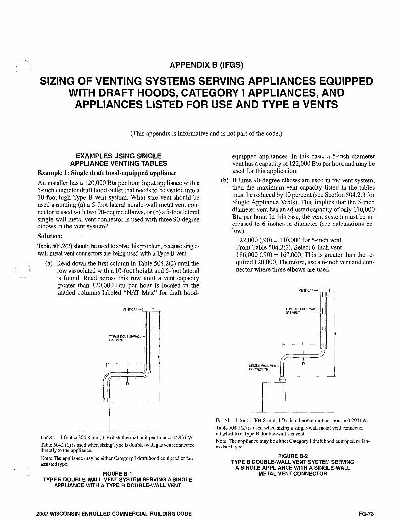
APPENDIX B (IFGS)
SIZING OF VENTING SYSTEMS SERVING APPLIANCES EQUIPPED WITH DRAFT HOODS, CATEGORY I APPLIANCES, AND
APPLIANCES LISTED FOR USE AND TYPE B VENTS
(This appendix is informative and is not part of the code.)
EXAMPLES USING SINGLE APPLIANCE VENTING TABLES
Example 1: Single draft hood-equipped appliance
An installer has a 120,000 Btu per hour input appliance with a 5-inch diameter draft hood outlet that needs to be vented into a 10-foot-high Type B vent system. What size vent should be used assuming (a) a 5-foot lateral single-wall metal vent connector is used with two 90-degree elbows, or (b) a 5-foot lateral single-wall metal vent connector is used with three 90-degree elbows in the vent system?
Solution:
Table 504.2(2) should be used to solve this problem, because singlewall metal vent connectors are being used with a Type B vent.
(a) Read down the first column in Table 504.2(2) until the row associated with a 10-foot height and 5-foot lateral is found. Read across this row until a vent capacity greater than 120,000 Btu per hour is located in the shaded columns labeled "NAT Max" for draft hood-
VENTCAP .------.
TYPE 8 DOUBLE·WALL -~ GAS VENT
H
r-------' --I
If 6
------·-
For SI: l foot = 304.8 mm, 1 Blitish thermal unit per hour= 0.2931 W.
Table 504.2(1) is used when sizing Type B double-wall gas vent connected directly to the appliance.
Note: The appliance may be either Category I draft hood equipped or fanassisted type,
FIGURE B-1 TYPE B DOUBLE-WALL VENT SYSTEM SERVING A SINGLE
APPLIANCE WITH A TYPE B DOUBLE-WALL VENT
2002 WISCONSIN ENROLLED COMMERCIAL BUILDING CODE
(b)
equipped appliances. In this case, a 5-inch diameter vent has a capacity of 122,000 Btu per hour and may be used for this application.
If three 90-degree elbows are used in the vent system, then the maximum vent capacity listed in the tables must be reduced by 10 percent (see Section 504.2.3 for Single Appliance Vents). This implies that the 5-inch diameter vent has an adjusted capacity ofonly 110,000 Btu per hour. In this case, the vent system must be increased to 6 inches in diameter (see calculations below).
122,000 (.90) = 110,000 for 5-inch vent From Table 504.2(2), Select 6-inch vent 186,000 (.90) = 167,000; This is greater than the required 120,000. Therefore, use a 6-inch vent and connector where three elbows are used.
VENT CAP
TYPE B DOUBLE-WALL GAS VENT l
H
""'"·WAL"""" ,;i---=·· =-~:-=·· -:::.~ I co""moA J
For SI: 1foot=304.8 mm, 1 British thermal unit per hour= 0.2931W.
Table 504.2(2) is used when sizing a single-wall metal vent connector attached to a 'fype B double-wall gas vent.
Note: The appliance may be either Category I draft hood equipped or fanassisted type.
FIGURE B-2 TYPE B DOUBLE-WALL VENT SYSTEM SERVING
A SINGLE APPLIANCE WITH A SINGLE-WALL METAL VENT CONNECTOR
FG-73
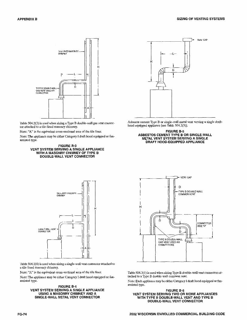
APPENDIX B
TILE·LINED MASONRY-CHIMNEY
r-L--I
me G" CON
B DOUBLE-WALL"""" b VENT USED AS NEC TOR
----~
-
-
H
l
--·-
A -·
1
Table 504.2(3) is used when sizing a T)'pe B double-wall gas vent connector attached to a tile-lined masom)' chimney.
Note: "A" is the equivalent cross-sectional area of the tile liner.
Note: The appliance may be either Category I draft hood equipped or fanassisted type.
FIGURE B-3 VENT SYSTEM SERVING A SINGLE APPLIANCE
WITH A MASONRY CHIMNEY OF TYPE B DOUBLE-WALL VENT CONNECTOR
' c
TILE·LINED MASONRY~ CHIMNEY
r-L-~
I
INGLE·WALL VENT~ 6 ONNECTOR
-
-
H
l
- -- ~
A ~
1
Table 504.2(4) is used when sizing a single-wall vent connector attached to a tile-lined masonry chimney.
Note: ''A" is the equivalent cross-sectional area of the tile liner.
Note: The appliance may be either Category I draft hood equipped or fanassisted type.
FG-74
FIGURE B·4 VENT SYSTEM SERVING A SINGLE APPLIANCE
USING A MASONRY CHIMNEY AND A SINGLE-WALL METAL VENT CONNECTOR
SIZING OF VENTING SYSTEMS
Asbestos cement Type B or single-wall metal vent serving a single drafthood-equipped appliance [see Table 504.2(5)].
FIGURE B·5 ASBESTOS CEMENT TYPE B OR SINGLE-WALL
METAL VENT SYSTEM SERVING A SINGLE DRAFT HOOD-EQUIPPED APPLIANCE
VENT CAP
- -o t--TYPE B DOUBLE-WALL
COMMON VENT
H l
··---- ----··--------·---- --·-----------
6~ l CONNECTOR
~ ' AISE"A'
6_,.\ ~ I ~1
TYPE B DOUBLE-WALL ----, GAS VENT USED AS CONNECTORS
Table 504.3(1) is used when sizing Type B double-wall vent connectors attached to a Type B double-wall common vent.
Note: Each appliance may be either Category I draft hood equipped or fanassisted type.
FIGURE B·6 VENT SYSTEM SERVING TWO OR MORE APPLIANCES
WITH TYPE B DOUBLE-WALL VENT AND TYPE B DOUBLE-WALL VENT CONNECTOR
2002 WISCONSIN ENROLLED COMMERCIAL BUILDING CODE

SIZING OF VENTING SYSTEMS
VENT CAP
- -D
--TYPE B DOUBLE-WALL COMMON VENT
H j '
/ - - -------------- ---------6 ~ I CONNECTOR
"~ AISE'R'
' 6 ' /'
'"/~ SINGLE-WALL VENT CONNECTORS
Table 504, 3(2) is used when sizing single-wall vent connectors attached to a Type B double-wall common vent.
Note: Each appliance may be either Category I draft hood equipped or fanassisted type.
FIGURE B·7 VENT SYSTEM SERVING TWO OR MORE APPLIANCES
WITH TYPE B DOUBLE-WALL VENT AND SINGLE-WALL METAL VENT CONNECTORS
_ ..... , __ , ____ --TILE-LINED MASONRY
CHIMNEY
- A ~
TYPE B DOUBLE-WALL H GAS VENT USED AS
CONNECTORS I
-----------~,~-j ' D I
6 ') J_ __,
~
Table 504.3(3) is used when sizing Type B double-wall vent connectors attached to a tile-lined masonry chimney.
Note: "A" is the equivalent cross-sectional area of the tile liner.
Note: Each appliance may be either Category I draft hood equipped or fanassisted type.
FIGURE B·8 MASONRY CHIMNEY SERVING TWO OR MORE APPLIANCES
WITH TYPE B DOUBLE-WALL VENT CONNECTOR
2002 WISCONSIN ENROLLED COMMERCIAL BUILDING CODE
APPENDIX B
f-- .... TILE-LINED MASONRY CHIMNEY
- A -
H SINGLE-WALL VENT CONNECTOR
\ I 7
----- -----. - ----- ------
6 I CONNECTOR
6 ' RISE"R'
=
i Table 504.3(4) is used when sizing single-wall metal vent connectors attached to a tile-lined masonry chimney.
Note: "A" is the equivalent cross-sectional area of the tile liner.
Note: Each appliance may be either Category I draft hood equipped or fanassisted type.
FIGURE B·9 MASONRY CHIMNEY SERVING TWO OR MORE APPLIANCES
WITH SINGLE·WALL METAL VENT CONNECTORS
VENT GAP
SEE SECTION 504.3.5 ---- Lo-
1 =, ~
H - -D
'' ''
I 1 l 1' '
j' -
1 2
Asbestos cement Type B or single-wall metal pipe vent serving two or more draft-hood-equipped appliances [see Table 504.3(5)].
FIGURE B-10 ASBESTOS CEMENT TYPE B OR SINGLE-WALL METAL VENT SYSTEM SERVING TWO OR MORE
DRAFT-HOOD-EQUIPPED APPLIANCES
FG-75

APPENDIX B
H
MANIFOLDCOMMON~LM-VENT CONNECTOR j ~
~!--CONNECTORS_., 1
1--~~-:~--------D
----------- --- ~
1 2
1
Example: Manifolded Conunon Vent Connector LM shall be no greater than 18 times the c01nmon vent connector manifold inside diameter; i.e., a 4-inch ( 102 mm) inside dimneter common vent connector manifold shall not exceed 72 inches (1829 mm) in length (sec Section 504.3.4).
Note: This is an illustration of a typical manifolded vent connector. Different appliance, vent connector, or common vent types are possible. Consult Section 502.3.
FIGURE 8·11 USE OF MANIFOLD COMMON VENT CONNECTOR
~-----------1:;;::::;?-VENTCAP
H
SEE SECTION 504.3,5
COMMON VENT
2
Example; Offset Common Vent
Note: This is an illustration of a typical offset vent. Different appliance, vent connector, or vent types are possible. Consult Sections 504.2 and 504.3.
FIGURE 8·12 USE OF OFFSET COMMON VENT
FG-76
SIZING OF VENTING SYSTEMS
"COl.l\!ON VENT SIZE &\SEOONALL INPUTS ENTERING THIS SEGMENT, AND AVAILABLE TOT Al HEIGHT
'TOTAL INPUT----+-
I
TEE SAME SIZE AS SEGMENT ASOVE
"AVAILABLE TOTAL HEIGHT "H' EQUALS RISE PLUS DISTANCE BETWEEN TEES
TEE SAME SIZEAS SEGMENT
~"
OTI!ERINPUTS FRO!,\ BELO\'/
Vent connector size depends on:
•Input
Common vent size depends on:
• Combined inputs
•Rise • Available total height "H'
•Available total height "H"
•Table 504.3(1) connectors
• Table504.3(l)common vent
FIGURE B-13 MULTISTORY GAS VENT DESIGN PROCEDURE
FOR EACH SEGMENT OF SYSTEM
USEIN!llVIDUllL 1'8lTFORTOPA.OOR
il.PRJANCEIF ~ CCfiNECTOll
REOJlnEMENTFOR r "'" AISEOFTOTllLHEIGHT , __ ,I ____ _.., umo~,.-
CA)l.\'OTElHIET I I
USE\IENT cctlNECRlfl TAEl.E
,, I j USEAVM.AEl..ETOTllLHEIGHTFOR
JI AVA'lAfllETOT/IL ~;,~~~CES , , HEIGHT FOR TOP 00 CCMllO!I VENT
11 FlOOfl APfUANCE
I llilA!l llITTAcctlllECTIOO TEE"
AVAILIE'!E TOTAL HBllHT FOO THIAC>fl_OOR APl'lll\NCEA)/!l CO,IB\'!EO INPIJTOFTIIAEE /\Pfl.U\,\'CES (IF TOP A.OOR N'f'tl.llNCEIStlOTcctlllECTEO, h18\SUAEOTOTllL HBGHTTO
-""
USEAVAil.AEl.E TOT/IL HE!Gfff FOil S~D-flOORAPfUN1CEN10 w.tlJ;/IEOflEATINPIJTOFTWO ~08
!lESlGN llHlTCCWIEGTol1 FOfl AAsr FlOOflAPFtWIGEASN-1, INDIVIDUN_ l@lTOfllllS TOTN_ HEIGHTFOFl INPIJT OF ARSf FlOOfl APPUmcE
c;r=====-=rmwm<~~rn•
•EACH ''ffEACCfillECflONTEE IS Sill.!E S\lEASTHE SEG'.!ENT OF COW.IO!l l@lT OIAECJLY Aall'E.
Principles of design of multistory vents using vent connector and common vent design tables (see Sections 504.3.10 through 504.3.15),
FIGURE B-14 MULTISTORY VENT SYSTEMS
2002 WISCONSIN ENROLLED COMMERCIAL BUILDING CODE
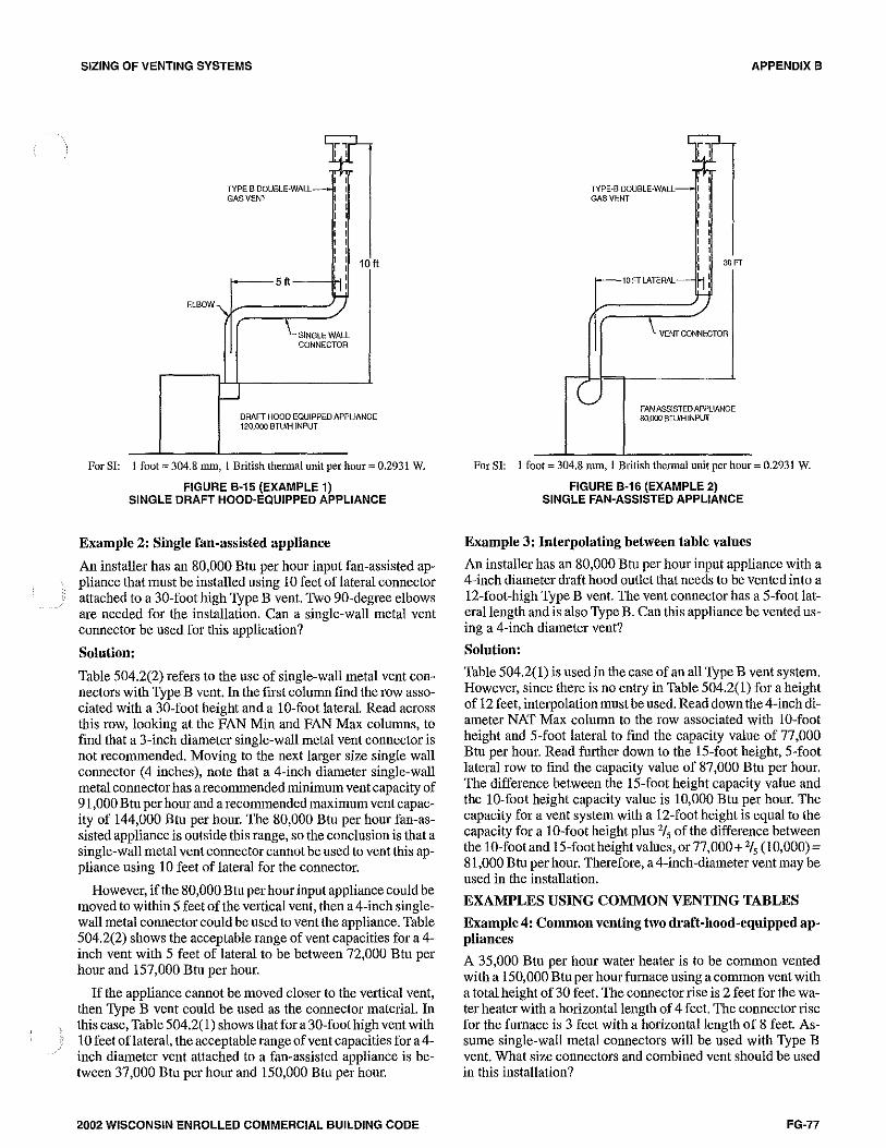
SIZING OF VENTING SYSTEMS
ELBOW
TYPE B DOUBLE-WALL GAS VENT
5 ft I I
I
7 \_SINGLE WALL
CONNECTOR
~
10
DRAFT HOOD EQUIPPED APPL!ANC 120,000 BTUfH JN PUT
E
For SI: l foot= 304.8 mm, 1 British thermal unit per hour= 0.2931 W.
FIGURE B-15 (EXAMPLE 1) SINGLE DRAFT HOOD-EQUIPPED APPLIANCE
Example 2: Single fan-assisted appliance
An installer has an 80,000 Btu per hour input fan-assisted appliance that must be installed using IO feet oflateral connector attached to a 30-foot high Type B vent. Two 90-degree elbows are needed for the installation. Can a single-wall metal vent connector be used for this application?
Solution:
Table 504.2(2) refers to the use of single-wall metal vent connectors with Type B vent. In the first column find the row associated with a 30-foot height and a IO-foot lateral. Read across this row, looking at the FAN Min and FAN Max columns, to find that a 3-inch diameter single-wall metal vent connector is not recommended. Moving to the next larger size single wall connector (4 inches), note that a 4-inch diameter single-wall metal connector has a recommended minimum vent capacity of 91,000 Btu per hour and a recommended maximum vent capacity of 144,000 Btu per hour. The 80,000 Btu per hour fan-assisted appliance is outside this range, so the conclusion is that a single-wall metal vent connector cannot be used to vent this appliance using IO feet of lateral for the connector.
However, if the 80,000 Btu per hour input appliance could be moved to within 5 feet of the vertical vent, then a 4-inch singlewall metal connector could be used to vent the appliance. Table 504.2(2) shows the acceptable range of vent capacities for a 4-inch vent with 5 feet of lateral to be between 72,000 Btu per hour and 157,000 Btu per hour.
If the appliance cannot be moved closer to the vertical vent, then Type B vent could be used as the connector matedal. In this case, Table 504.2(1) shows that fora 30-foothigh vent with IO feet oflateral, the acceptable range of vent capacities for a 4-inch diameter vent attached to a fan-assisted appliance is between 37,000 Btu per hour and 150,000 Btu per hour.
2002 WISCONSIN ENROLLED COMMERCIAL BUILDING CODE
TYPE·B DOUBLE-WALL GAS VENT
10 FT LATERAL
30 FT
VENT CONNECTOR
FANASSISTEDAPPUANGE 80,000Bn.JMINPUT
APPENDIX B
For SI: 1foot:::::304.8 mm, l British thermal unit per hour= 0.2931 W.
FIGURE B-16 (EXAMPLE 2) SINGLE FAN-ASSISTED APPLIANCE
Example 3: Interpolating between table values
An installer has an 80,000 Btu per hour input appliance with a 4-inch diameter draft hood outlet that needs to be vented into a 12-foot-high Type B vent. The vent connector has a 5-foot lateral length and is also Type B. Can this appliance be vented using a 4-inch diameter vent?
Solution:
Table 504.2( 1) is used in the case of an all Type B vent system. However, since there is no entry in Table 504.2(1) for a height of 12 feet, interpolation must be used. Read down the 4-inch diameter NAT Max column to the row associated with IO-foot height and 5-foot lateral to find the capacity value of 77,000 Btu per hour. Read further down to the 15-foot height, 5-foot lateral row to find the capacity value of 87 ,000 Btu per hour. The difference between the 15-foot height capacity value and the 10-foot height capacity value is I0,000 Btu per hour. The capacity for a vent system with a 12-foot height is equal to the capacity for a IO-foot height plus 2/ 5 of the difference between the IO-foot and 15-footheight values, or 77,000+ 2/5 (I 0,000) = 81,000 Btu per hour. Therefore, a 4-inch-diameter vent may be used in the installation.
EXAMPLES USING COMMON VENTING TABLES
Example 4: Common venting two draft-hood-equipped appliances
A 35,000 Btu per hour water heater is to be common vented with a 150,000 Btu per hour furnace using a common vent with a total height of 30 feet. The connector rise is 2 feet for the water heater with a hodzontal length of 4 feet. The connector rise for the furnace is 3 feet with a horizontal length of 8 feet. Assume single-wall metal connectors will be used with Type B vent. What size connectors and combined vent should be used in this installation?
FG-77

APPENDIX B
t •
DAAFT HOOD-EQUIPPED WATER HEATER
35,000STilHINPUT
COMBINEDCAPAC!TY 35.M+ 150,000~ 165,000BTU\1
TYPE 8 OOVBLE-WAll
""''""
DRAFT HOOD-EQUIPMENT FURN/I.CE
150000BTU1-ilNPUT
FIGURE B-17 (EXAMPLE 4) COMMON VENTING TWO DRAFT HOOD-EQUIPPED APPLIANCES
Solution:
Table 504.3(2) should be used to size single-wall metal vent connectors attached to Type B vertical vents. In the vent connector capacity portion of Table 504.3(2), find the row associated with a 30-foot vent height. For a 2-foot rise on the vent connector for the water heater, read the shaded cohunns for draft hood-equipped appliances to find that a 3-inch-diameter vent connector has a capacity of 37,000 Btu per hour. Therefore, a 3-inch single-wall metal vent connector may be used with the water heater. For a draft-hood-equipped furnace with a 3-foot rise, read across the appropriate row to find that a 5-inchdiameter vent connector has a maxitnum capacity of 120,000 Btu per hour (which is too small for the furnace) and a 6-inchdiameter vent connector has a inaximu1n vent capacity of 172,000 Btu per hour. Therefore, a 6-inch-diameter vent connector should be used with the 150,000 Btu per hour furnace. Since both vent connector horizontal lengths are less than the maximum lengths listed in Section 504.3.2, the table values may be used without adjustments.
In the common vent capacity portion of Table 504.3(2), find the row associated with a 30-foot vent height and read over to the NAT+ NAT portion of the 6-inch diameter column to find a maximum combined capacity of257,000 Btu per hour. Since the two appliances total only 185,000 Btu per hour, a 6-inch common vent may be used.
Example Sa: Common venting a drnft-hood-equipped water heater with a fan-assisted furnace into a Type B vent
FG-78
SIZING OF VENTING SYSTEMS
In this case, a 35,000 Btu per hour input draft-hoodequipped water heater with a 4-inch-diameter draft hood outlet, 2 feet of connector rise, and 4 feet of horizontal length is to be common vented with a 100,000 Btu per hour fan-assisted furnace with a 4-inch-diameter flue collar, 3 feet of connector rise, and 6 feet of horizontal length. The common vent consists of a 30-foot height of Type B vent. What are the recommended vent diameters for each connector and the common vent? The installer would like to use a single-wall metal vent connector.
Solution: - [Table 504.3(2)]
Water Heater Vent Connector Diameter. Since the water heater vent connector horizontal length of 4 feet is less than the maximum value listed in Section 504.3.2, the venting table values may be used without adjustments. Using the Vent Connector Capacity portion of Table 504.3(2), read down the Total Vent Height (H) column to 30 feet and read across the 2-foot Connector Rise (R) row to the first Btu per hour rating in the NAT Max column that is equal to or greater than the water heater input rating. The table shows that a 3-inch vent connector has a maximum input rating of 37,000 Btu per hour. Although this is greater than the water heater input rating, a 3-inch vent connector is prohibited by Section 504.3.19. A 4-inch vent connector has a maximum input rating of 67,000 Btu per hour and is equal to the draft hood outlet diameter. A 4-inch vent connector is selected. Since the water heater is equipped with a draft hood, there are no 1ninimum input rating restrictions.
Furnace Vent Connector Diameter. Using the Vent Connector Capacity portion of Table 504.3(2), read down the Total Vent Height (H) column to 30 feet and across the 3-foot Connector Rise (R) row. Since the furnace has a fan-assisted combustion system, find the first FAN Max column with a Btu per hour rating greater than the furnace input rating. The 4-inch vent connector has a maximum input rating of 119,000 Btu per hour and a minimum input rating of 85,000 Btu per hour. The 100,000 Btu per hour furnace in this example falls within this range, so a 4-inch connector is adequate. Since the furnace vent connector hmizontal length of 6 feet does not exceed the maximum value listed in Section 504.3.2, the venting table values may be used wilhout adjustment. If the furnace had an input rating of 80,000 Btu per hour, then a Type B vent connector [see Table 504.3(1)] would be needed in order to meet the minimum capacity limit.
Common Vent Diameter. The total input to the common vent is 135,000 Btu per hour. Using the Common Vent Capacity portion of Table 504.3(2), read down the Total Vent Height (H) column to 30 feet and across this row to find the smallest vent diameter in the FAN+ NAT column that has a Btu per hour rating equal to or greater than 135,000 Btu per hour. The 4-inch common vent has a capacity of 132,000 Btu per hour and the 5-inch common vent has a capacity of 202,000 Btu per hour. Therefore, the 5-inch common vent should be used in this example.
Summary. In this example, the installer may use a 4-inch-diameter, single-wall metal vent connector for the water heater and a 4-inch-diameter, single-wall metal vent connector for the furnace. The common vent should be a 5-inch-diameter Type B vent.
2002 WISCONSIN ENROLLED COMMERCIAL BUILDING CODE

SIZING OF VENTING SYSTEMS
TYPEBOOUBLE·WALL GAS VENT
COMBINED CAPACITY 35.!JOO+ 100,000,,, 135,000BTU'l-I
FAN-ASSISTED
""""' 100,000BTUH
"""
SINGLE-WALL CONNECTORS
FIGURE B-18 (EXAMPLE 5A)
WATER HEATER 35,CQO BTU1-t
INPLJT
COMMON VENTING A DRAFT HOOD WITH A FAN-ASSISTED FURNACE INTO A TYPE B DOUBLE-WALL COMMON VENT
Example Sb: Common venting into a masonry chimney
In this case, the water heater and fan-assisted furnace of Example Sa are to be common vented into a clay tile-lined masonry chimney with a 30-foot height. The chimney is not exposed to the outdoors below the roofline. The internal dimensions of the clay tile liner are nominally 8 inches by 12 inches. Assuming the same vent connector heights, laterals, and materials found in Exatnple 5a, what are the recommended vent connector diameters, and is this an acceptable installation?
Solution:
Table S04.3( 4) is used to size common venting installations involving single-wall connectors into 1nasom·y chiinneys.
Water Heater Vent Connector Diameter. Using Table S04.3(4), Vent Connector Capacity, read down the Total Vent Height (HJ column to 30 feet, and read across the 2-foot Connector Rise (R) row to the first Btu per hour rating in the NAT Max column that is equal to or greater than the water heater input rating. The table shows that a 3-inch vent connector has a maximum input of only 31,000 Btu per hour while a 4-inch vent connector has a 1naximu1n input of 57,000 Btu per hour. A 4-inch vent connector inust therefore be used.
Furnace Vent Connector Diameter. Using the Vent Connector Capacity portion of Table S04.3(4), read down the Total Vent Height (HJ column to 30 feet and across the 3-foot Connector Rise (R) row. Since the furnace has a fan-assisted combustion system, find the first FAN Max column with a Btu per hour rating greater than the furnace input rating. The 4-inch
2002 WISCONSIN ENROLLED COMMERCIAL BUILDING CODE
APPENDIX B
vent connector has a maximum input rating of 127,000 Btu per hour and a minimum input rating of 9S,OOO Btu per hour. The 100,000 Btu per hour furnace in this example falls within this range, so a 4-inch connector is adequate.
Maso my Chimney. From Table B-1, the equivalent area for a nominal liner size of 8 inches by 12 inches is 63.6 square inches, Using Table S04.3(4), Common Vent Capacity, read down the FAN + NAT column under the Minimum Internal Area of Chimney value of 63 to the row for 30-foot height to find a capacity value of 739,000 Btu per hour. The combined input rating of the furnace and water heater, 13S,OOO Btu per hour, is less than the table value, so this is an acceptable installation,
Section S04.3. lS requires the common vent area to be no greater than seven times the smallest listed appliance catego-1ized vent area, flue collar area, or draft hood outlet area. Both appliances in this installation have 4-inch-diameter outlets. From Table B-1, the equivalent area for an inside diameter of 4 inches is 12.2 square inches. Seven times 12.2 equals 8S.4, which is greater than 63.6, so this configuration is acceptable.
Example Sc: Common venting into an exterior masonry chimney
In this case, the water heater and fan-assisted furnace of Examples Sa and Sb are to be common vented into an exterior masonry chimney. The chimney height, clay tile liner dimensions, and vent connector heights and laterals are the same as in Example Sb. This system is being installed in Charlotte, North Carolina. Does this exterior masonry chimney need to be relined? If so, what corrugated metallic liner size is reco1n-1nended? What vent connector diameters are recommended?
Solution:
According to Section S04.3.18, Type B vent connectors are required to be used with exterior masonry chimneys. Use Table S04.3(8) to size FAN+NAT common venting installations involving Type-B double wall connectors into extedor masomy chimneys.
The local 99-percent winter design temperature needed to use Table S04.3(8) can be found in the ASHRAE Handbook of Fundan1en.tals. For Charlotte, North Carolina, this design te1nperature is 19°F.
Chimney Liner Requirement, As in Example Sb, use the 63 square inch Internal Area columns for this size clay tile line1: Read down the 63 square inch column of Table S04.3(8a) to the 30-foot height row to find that the combined appliance maximum input is 747 ,000 Btu per hour. The combined input rating of the appliances in this installation, 13S,OOO Btu per hour, is less than the maximum value, so this criterion is satisfied. Table S04.3(8b), at a l9°F Design Temperature, and at the same vent height and internal area used above, shows that the minitnum allowable input rating of a space-heating appliance is 470,000 Btu per hour. Thefurnace input rating of 100,000 Btu per hour is less than this 1ninimum value. So this criterion is not satisfied, and an alternative venting design needs to be used, such as a Type B vent shown in Example Sa or a listed chimney liner syste1n shown in the re1nainder of the exa1nple.
FG-79

APPENDIX B
According to Section 504.3.17, Table 504.3(1) or 504.3(2) is used for sizing corrugated metallic liners in masom·y chimneys, with the maximum common vent capacities reduced by 20 percent. This example will be continued assuming Type B vent connectors.
Water Heater Vent Connector Diameter. Using Table 504.3(1), Vent Connector Capacity, read down the Vent Height (H) column to 30 feet, and read across the 2-foot Connector Rise (R)row to the first Btu per hour rating in the NAT Max column that is equal to or greater than the water heater input rating. The table shows that a 3-inch vent connector has a maximum capacity of39,000 Btu per hour. So the 35,000 Btu per hour water heater in this example can use a 3-inch connector.
Furnace Vent Connector Diameter. Using Table 504.3(1), Vent Connector Capacity, read down the Vent Height (H) column to 30 feet, and read across the 3-foot Connector Rise (R) row to the first Btu per hour rating in the FAN Max column that is equal to or greater than the furnace input rating. The 100,000 Btu per hour furnace in this example falls within this range, so a 4-inch connector is adequate.
Chimney Liner Diameter. The total input to the common vent is 135,000 Btu per hour. Using the Common Vent Capacity Portion of Table 504.3(1), read down the Vent Height (H) coltnnn to 30 feet and across this row to find the smallest vent diameter in the FAN+NAT column that has a Btu per hour rating greater than 135,000 Btu per hour. The 4-inch common vent has a capacity of 138,000 Btu per hour. Reducing the maximum capacity by 20 percent (Section 504.3.17) results in a maximum capacity for a4-inch corrugated liner of 110,000 Btu per hour, less than the total input of 135,000 Btu per hour. So a larger liner is needed. The 5-inch common vent capacity listed in Table 504.3(1) is 210,000 Btu per hour, and after reducing by 20 percent is 168,000 Btu per hour. Therefore, a 5-inch corrugated metal liner should be used in this example.
Single-Wall Connectors. Once it has been established that relining the chimney is necessary, Type B double-wall vent connectors are not specifically required. This example could be redone using Table 504.3(2) for single-wall vent connectors. For this case, the vent connector and liner diameters would be the same as found above with Type B double-wall connectors.
FG·BO
SIZING OF VENTING SYSTEMS
TABLE B·1 MASONRY CHIMNEY LINER DIMENSIONS
WITH CIRCULAR EQUIVALENTS•
INSIDE INSIDE DIAMETER OR
NOMINAL DIMENSIONS EQUIVALENT EQUIVALENT LINER SIZE OF LINER DIAMETER AREA
(inches) {inches) (Inches) (square Inches)
4 12.2
2112 x 61/2 5 19.6
4x8 6 28.3
7 38.3
63/4 x 63/4 7.4 42.7
8x8 8 50.3
611, x 10'!, 9 63.6
8 x 12 10 78.5
93/4x93/4 10.4 83.3
12 x 12 11 95
11.8 107.5
12 x 16 911, x 13 11, 12 113.0
14 153.9
1311, x 13114 14.5 162.9
16 x 16 15 176.7
16.2 206.l 16 x 20 13 x 17
18 254.4
16314 x 16314 18.2 260.2
20 x 20 20 314.1
16'1, x 2011, 20.1 314.2
20 x 24 22 380.l
2011, x 2011, 22.1 380.1
24 x24 24 452.3
24 X28 2011, x 2011., 24.1 456.2
24114 x 2411, 26.4 543.3
28 x28 27 572.5
2511, x 25 11, 27.9 607
30 x 30 30 706.8
25112 x 31 112
30.9 749.9 30x 36
33 855.3
31 11, x 31 11, 34.4 929.4
36 x 36 36 1017.9
For SI: 1inch=25.4 mm, 1 square inch= 645.16 ni2. a. Where liner sizes differ dimensionally from those shown in Table B-1,
equivalent diameters may be determined from published tables for square and rectangular ducts of equivalent carrying capacity or by other engineering methods.
2002 WISCONSIN ENROLLED COMMERCIAL BUILDING CODE

APPENDIX C Deleted
2002 WISCONSIN ENROLLED COMMERCIAL BUILDING CODE FG-81

FG-82 2002 WISCONSIN ENROLLED COMMERCIAL BUILDING CODE

APPENDIX D Deleted
2002 WISCONSIN ENROLLED COMMERCIAL BUILDING CODE FG-83

FG·B4 2002 WISCONSIN ENROLLED COMMERCIAL BUILDING CODE
INDEX
A Floor furnaces .................. 608.4, 608.6
ACCESS, APPLIANCES Open top broiler units ................ 622.5.1
Duct furnaces ........................ 609.3 Refrigerators ......................... 624.1
General .............................. 306 Unit heater .......................... 619.4
Wall furnaces, vented .................. 607.6 CLOTHES DRYERS
ADJUSTMENTS .................... 607.6, 620.6 Defined .............................. 202
ADMINISTRATION .................... Chapter 1 Exhaust .............................. 613
Alternate methods of sizing chimneys .... 503.5.5 General .............................. 612
Violations and penalties ................. 108 CODE OFFICIAL
AIR, COMBUSTION Deli ned . . . . . . . . . . . . . . . . . . . . . . . . . . . . . . 202
Defined .............................. 202 COMBUSTION AIR
Requirements .................. 303.3(1 ), 304 Confined space ............... 304.10, 304.11
AIR CONDITIONING EQUIPMENT . ............ 626 Defined .............................. 202
Clearances .......................... 308.3 Direct openings outside .............. 304.12.2
APPLIANCES Exhaust effect. ....................... 304. 7
Broilers for indoor use ................. 622.5 Free area ................... 304.10, 304.11,
Cooking .............................. 622 Decorative ............................ 602
304.12, 304.14 Horizontal ducts ............ 304.11.1, 304.12.3
Decorative vented .............. 202, 303.3(2), Table 503.4, 604
Sources of (from) .................. 304.15(4) Sauna heaters ....................... 614.5
Domestic ranges ..................... 622.4 Unconfined space .............. 304.9, 304.1 O
Electrical ............................. 309 Unconfined space, but unusually tight ..... 304.9
Installation ....................... Chapter 6 Vertical ducts ...... 304.11.1, 304.11.2, 304.12.4
Prohibited locations ................... 303.3 CONDENSATE DISPOSAL. .................. 307
Protection from damage ................ 303.4 CONTROLS Boilers ............................. 630.2
B BOILERS
Listed ................................ 630 Prohibited locations ................... 303.3 Unlisted .............................. 631
Gas pressure regulators ................ 627.4 CONVERSION BURNERS ........... 503.12.1, 618 COOKING APPLIANCES .................... 622 CREMATORIES . ........................... 605 CUTTING, NOTCHING, AND
BORED HOLES . ........................ 302.3
c D CENTRAL FURNACES
Defined .............................. 202 CHIMNEYS .......................... Chapter 5
Alternate methods of sizing ............ 503.5.5 Clearance reduction .................... 308 Damper opening area ................... 632 Defined .............................. 202
CLEARANCE REDUCTION .................. 308 CLEARANCES
DAMPERS, VENT . ....................... 506.14 DECORATIVE APPLIANCES ................. 602 DEFINITIONS ........................ Chapter 2 DIRECT VENT APPLIANCES
Defined .............................. 202 Installation .......................... 304.1
DRAFT HOODS ..................... 202, 503.12 DUCT FURNACES ..................... 202, 609
Air conditioning equipment .............. 626.4 Boilers ............................. 308.4 E Domestic ranges ..................... 622.4 ELECTRICAL CONNECTIONS .............. 309.2
2002 WISCONSIN ENROLLED COMMERCIAL BUILDING CODE FG-85
INDEX
EXHAUST SYSTEMS ......... 202, 503.2.1, 503.3.4
F FLOOD HAZARD . ....................... 301 .11 FLOOR FURNACES ........................ 608 FURNACES
Central heating, clearance .............. 308.4 Duci ................................. W9 Floor ................................ 608 Prohibited location .................... 303.3 Vented wall ........................... 607
G GARAGE, INSTALLATION ....... 305.2, 305.3, 305.4 GROUNDING, PIPE ....................... 309.1
H HOT PLATES AND LAUNDRY
STOVES ...................... 501.8(3), 622.1
ILLUMINATING APPLIANCES ................ 627 INCINERATORS ....................... 605, 606 INFRARED RADIANT HEATERS .............. 629 INSTALLATION, APPLIANCES
Garage .............................. 305 Listed and unlisted appliances ..... 301.3, 305.1 General .............................. 301 Specific appliances ................ Chapter 6
K KILNS ................................... 628
L LIQUEFIED PETROLEUM GAS
Defined .............................. 202 LOG LIGHTERS ........................... 603
M MAKE-UP AIR HEATERS . ............... 610, 611
Industrial ............................. 611 Venting ........................... 501.8(9)
MATERIALS, DEFECTIVE Repair .............................. 301.9
MINIMUM SAFE PERFORMANCE, VENT SYSTEMS . ....................... 503.3
0 OXYGEN DEPLETION SYSTEM
FG-86
Defined .............................. 202 Unvented room heaters ......... 303.3(3), 620.6
p POOL HEATERS . .......................... 616 PROHIBITED INSTALLATIONS
Floor furnaces ....................... 608.2 Fuel burning appliances ................ 303.3 Unvented room heater ................. 620.4 Vent connectors .................. 503.3.3(3)
R RADIANT HEATERS . ....................... 629 RANGES, DOMESTIC ..................... 622.4 REFRIGERATORS .................. 501.8(6), 624 REGULATORS, PRESSURE ................ 627.4 ROOFTOP INSTALLATIONS . ............... 306.5 ROOM HEATERS
Defined .............................. 202 Location ............................ 303.3 Unvented ............................. 620 Vented ............................... 621
s SAFETY SHUTOFF DEVICES
Direct gas-fired make-up air heaters ...... 610.5 Flame safeguard device ................ 602.2 Unvented room heaters ................ 620.6
SAUNA HEATERS .......................... 614 SEISMIC RESISTANCE ................... 301.12 SERVICE SPACE .......................... 306 SPA HEATERS ............................ 616 STANDARDS . ........................ Chapter 7 STRUCTURAL SAFETY ................... 302.1
T THIMBLE, VENT ............... 503.6.3, 503.10.12,
503.10.16 TOILETS ................................. 625
u UNCONFINED SPACES ............ 304.10, 304.11 UNIT HEATERS ............................ 619 UNLISTED BOILERS ....................... 631 UNUSUALLY TIGHT ............ 202, 304.9, 304.12 UNVENTED ROOM HEATERS . ............... 620
v VENTILATING HOODS . ........... 503.2.1, 503.3.4
2002 WISCONSIN ENROLLED COMMERCIAL BUILDING CODE
INDEX
VENTED DECORATIVE APPLIANCES ............................ 604
VENTED ROOM HEATERS .................. 621 VENTED WALL FURNACES ................. 607 VENTS
Caps ............................ 504.3.14 Direct vent ......................... 503.2.3 Equipment not requiring vents ........... 501.8 Gas vent termination ................. 503.6.7 General ......................... Chapter 5 Integral .............................. 505 Listed and labeled .................... 502.1 Mechanical vent ....................... 505
VENT, SIZING Category I appliances ................... 502 Multiappliance ....................... 504.3 Multistory ......... 504.3.12, 504.3.13, 504.3.14 Single appliance ...................... 504.2
VIBRATION ISOLATION ................... 301.8 VIOLATIONS AND PENALTIES ............... 108
w WALL FURNACES, VENTED ................. 607 WARM AIR FURNACES ..................... 617 WATER HEATERS ......................... 623
Garage installation ..................... 305 WIND RESISTANCE . ..................... 301.10
2002 WISCONSIN ENROLLED COMMERCIAL BUILDING CODE FG-87

FG-88 2002 WISCONSIN ENROLLED COMMERCIAL BUILDING CODE


![Technical specifications PLACI.pdf · 6:17 Technical specifications Plate types T2B M3/M3D TL3B/TL3P/TL3BD T5M/T5B M6, M6M, M6MD Frame type FG FG FG FG FG FD Height, H [mm] 380 480](https://img.pdfslide.us/doc/110x75/60d1fca979eea3753279e64f/technical-placipdf-617-technical-specifications-plate-types-t2b-m3m3d-tl3btl3ptl3bd.jpg)