Embed Size (px)
Citation preview

FF-S
YB
1Safety Products for Machine Safeguarding - © 2003 - 2005 Honeywell International Inc. All rights reserved.
! WARNINGMISUSE OF DOCUMENTATION
• The information presented in this product sheet (or catalogue) is for reference only. DO NOT USE this documentas system installation information.
• Complete installation, operation and maintenance information is to be referenced for each product.
Failure to comply with these instructions could result in death or serious injury.
Type 4 Safety light curtainCompact, Universal, Smart and Full-featured
FF-SYB Series
FEATURES• 1- or 2-beam floating blanking• Manual or automatic restart• External Device Monitoring (EDM)• 2 or 4 inputs for muting signals• Manual muting override• Input for serial connection of an
auxiliary safety device• Unique patented configuration cards for
quick set-up and easy replacement• Self-contained with optical synchro-
nisation• 2 static (solid state) safety outputs with
short-circuit and cross-fault detection• Muting lamp/diagnosis output or
static (solid state) non safety output forsignalling
• Selection of the infrared emission powerallows cross-talk reduction
• Enhanced diagnostic informationincludes the following indication: signalstrength, cross-talk, muting, blanking,restart and failure diagnostic
• Test input with selectable test input type• Resolutions available:
ø14 mm / 0.6 in for finger detectionø30 mm / 1.2 in for hand detectionø50 mm / 1.97 in for leg detection
• Protection height up to 1830 mm / 72 in• Scanning range up to 20 m / 65 ft• M12 connectors• Mounting brackets included allowing
multiple mounting positions• Safety relay modules for more switching
capability (to be ordered separately).
TYPICAL APPLICATIONS• Presses and punches• Metal-forming, milling and drilling
machines• Spot-welding machines and fine-boring
machines• Pressing, moulding and thermoforming
machines• Stacking machines, transporting and
conveyor technology; handlingequipment and assembly lines
• Palletizing industry
Type 4per IEC/EN 61496-1/2
Approved as
The Honeywell FF-SYB light curtain is in compliance with IEC/EN 61496 - parts 1and 2 standard and meets the requirements for a Type 4 Active OptoelectronicProtective Device, the highest level for safety products.
The product received an EC type test certificate from the French INRS notified body,required for safety equipment as per the 98/37/EC Machinery Directive. It meets theapplicable parts of North American standards and regulations (OSHA 1910.212,OSHA 1910.217, ANSI standards including ANSI RIA 15.06 for Control Reliabilityand CSA Z434). The CSA marking makes it a product usable in most parts of theworld.
As soon as an object is detected inside the protection field, the FF-SYB de-energizesits two static (solid state) safety outputs to signal the dangerous motion to stop.The FF-SYB is a self-contained light curtain that does not require a separate controlunit for operation.
Functions such as floating blanking, muting, external device monitoring, manualrestart and serial connection make it a comprehensive product and eliminate theneed for additional control modules.
These built-in features, combined with the small size of the housing, help usersreduce overall cost by saving space and installation time.
A unique patented configuration card system allows the user to set up the correctoperating mode when swapping units, by simplifying and reducing the number ofoperations.
FF-SYB
2 Safety Products for Machine Safeguarding - © 2003 - 2005 Honeywell International Inc. All rights reserved.
External Device Monitoring (EDM)The FF-SYB is fitted with an EDM input which allows users to check the correct state of the final switching devices (relays orcontactors with positively guided contacts). After each intrusion into the protection field, the FF-SYB will check that the EDM inputloop is closed before switching the outputs back to ON. If the FF-SYB operates in automatic restart mode, it will restart immediatelyif the EDM loop is closed. If the FF-SYB operates in manual restart mode, it will restart when the restart push-button is pressed andif the EDM loop is closed. If the EDM loop remains open (meaning that the external device has a malfunction) the FF-SYB will keepits outputs open and will not restart.
Manual restartThe FF-SYB can be used in automatic or manual restart mode. In automatic mode, the outputs will switch back to ON after aninterruption of the protection field, as soon as the field becomes clear again. In manual restart mode, the FF-SYB will not switch backits outputs to ON until a manual restart push-button is pressed and released. The push-button must be a normally open type button.The manual restart will not switch the OSSDs back to ON in case of light curtain lock out (internal failure, optical interference, etc.)or when the protection field is still interrupted.
Auxiliary outputAn additional non safety output is available to either mimic the safety output status (solid state Normally Closed signalling output)or signal muting sequences and provide diagnostic information (mode selection depending).
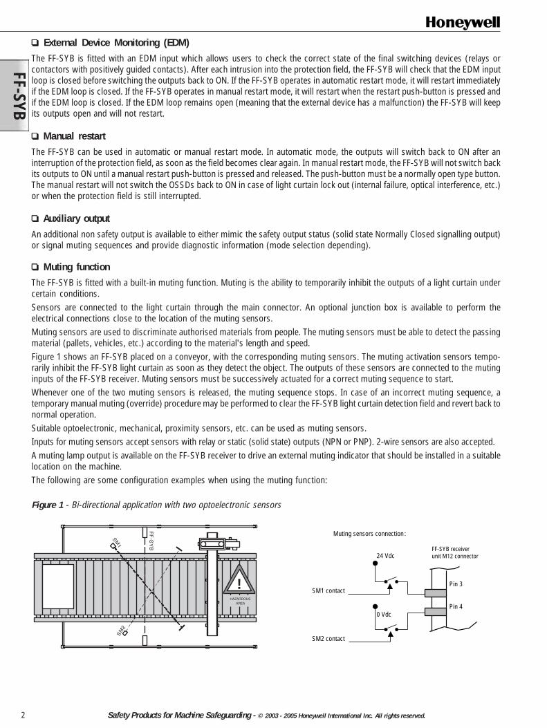
Muting functionThe FF-SYB is fitted with a built-in muting function. Muting is the ability to temporarily inhibit the outputs of a light curtain undercertain conditions.Sensors are connected to the light curtain through the main connector. An optional junction box is available to perform theelectrical connections close to the location of the muting sensors.Muting sensors are used to discriminate authorised materials from people. The muting sensors must be able to detect the passingmaterial (pallets, vehicles, etc.) according to the material's length and speed.Figure 1 shows an FF-SYB placed on a conveyor, with the corresponding muting sensors. The muting activation sensors tempo-rarily inhibit the FF-SYB light curtain as soon as they detect the object. The outputs of these sensors are connected to the mutinginputs of the FF-SYB receiver. Muting sensors must be successively actuated for a correct muting sequence to start.Whenever one of the two muting sensors is released, the muting sequence stops. In case of an incorrect muting sequence, atemporary manual muting (override) procedure may be performed to clear the FF-SYB light curtain detection field and revert back tonormal operation.Suitable optoelectronic, mechanical, proximity sensors, etc. can be used as muting sensors.Inputs for muting sensors accept sensors with relay or static (solid state) outputs (NPN or PNP). 2-wire sensors are also accepted.A muting lamp output is available on the FF-SYB receiver to drive an external muting indicator that should be installed in a suitablelocation on the machine.The following are some configuration examples when using the muting function:
Figure 1 - Bi-directional application with two optoelectronic sensors
Muting sensors connection:
SM1 contact
SM2 contact
24 Vdc
0 Vdc
Pin 3
Pin 4
FF-SYB receiverunit M12 connector
!
FF
-SY
B
SM1
SM
2
HAZARDOUSAREA
FF-S
YB
3Safety Products for Machine Safeguarding - © 2003 - 2005 Honeywell International Inc. All rights reserved.
SM1 contact
EM1 contact
SM2 contact
EM2 contact
24 Vdc
0 Vdc
FF-SYB receiverunit terminal strip
pin 9
pin 3
pin 10
pin 4
Muting sensors connection:
SM1 contact
SM3 contact
SM2 contact
SM4 contact
24 Vdc
0 Vdc
FF-SYB receiverunit M12 connector
Pin 3
Pin 4
Muting sensors connection:
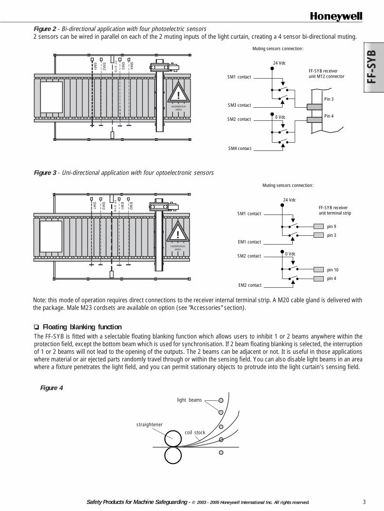
Figure 3 - Uni-directional application with four optoelectronic sensors
Figure 2 - Bi-directional application with four photoelectric sensors2 sensors can be wired in parallel on each of the 2 muting inputs of the light curtain, creating a 4 sensor bi-directional muting.
!
SM
1
SM
2
FF
-SY
B
SM
3
SM
4
HAZARDOUSAREA
!
SM
1
SM
2
EM
1
EM
2
FF
-SY
B
HAZARDOUSAREA
Floating blanking functionThe FF-SYB is fitted with a selectable floating blanking function which allows users to inhibit 1 or 2 beams anywhere within theprotection field, except the bottom beam which is used for synchronisation. If 2 beam floating blanking is selected, the interruptionof 1 or 2 beams will not lead to the opening of the outputs. The 2 beams can be adjacent or not. It is useful in those applicationswhere material or air ejected parts randomly travel through or within the sensing field. You can also disable light beams in an areawhere a fixture penetrates the light field, and you can permit stationary objects to protrude into the light curtain's sensing field.
Figure 4
light beams
coil stockstraightener
Note: this mode of operation requires direct connections to the receiver internal terminal strip. A M20 cable gland is delivered withthe package. Male M23 cordsets are available on option (see "Accessories" section).
FF-SYB
4 Safety Products for Machine Safeguarding - © 2003 - 2005 Honeywell International Inc. All rights reserved.
The maximum size of an undetected object is also affected by floating blanking:
When using floating blanking, the resolution of the light curtain is altered according to the following table:
Resolutionwithout floating/
blanking
Resolutionwith 1-beam
floating blanking
Resolutionwith 2-beam
floating blanking Model
FF-SYB14 14 mm / 0.55 in 24 mm / 0.94 in 34 mm / 1.33 in FF-SYB30 30 mm / 1.18 in 50 mm / 1.97 in 70 mm / 2.75 in FF-SYB50 50 mm / 1.97 in 90 mm / 3.54 in 130 mm / 5.12 in
Maximum size ofundetected object
with 1-beam floating blanking
Maximum size ofundetected object
with 2-beam floating blanking FF-SYB14 6 mm / 0.23 in 16 mm / 0.63 in FF-SYB30 10 mm / 0.39 in 30 mm / 1.18 in FF-SYB50 30 mm / 1.18 in 70 mm / 2.75 in
Model
FF-SYB safety light curtain
Safety mat
Serial connectionThe FF-SYB safety light curtain allows the connection of another safety device with dual outputs through 2 inputs on the receiverunit. The auxiliary safety device can be an electromechanical safety switch or any other safety device with either relay outputs orsolid state outputs (for safety reasons, reversed polarity on these two inputs is mandatory, therefore connection of a secondFF-SYB light curtain is not possible through these two inputs). Connection is done through the main connector. An optionaljunction box is available to perform the electrical connections close to the light curtain.
Configuration cards
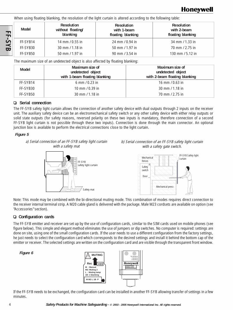
The FF-SYB emitter and receiver are set up by the use of configuration cards, similar to the SIM cards used on mobile phones (seefigure below). This simple and elegant method eliminates the use of jumpers or dip switches. No computer is required: settings aredone on site, using one of the small configuration cards. If the user needs to use a different configuration from the factory settings,he just needs to select the configuration card which corresponds to the desired settings and install it behind the bottom cap of theemitter or receiver. The selected settings are written on the configuration card and are visible through the transparent front window.
If the FF-SYB needs to be exchanged, the configuration card can be installed in another FF-SYB allowing transfer of settings in a fewminutes.
M : ManualM2: Muting 2L : Muting lamp1B: 1 blanking
M M2 L 1B P
MUTING
#23
!
Rec
Figure 6
Figure 5
a) Serial connection of an FF-SYB safety light curtainwith a safety mat
b) Serial connection of an FF-SYB safety light curtainwith a safety gate switch.
Door
Mechanical press
Safetyswitch
Mechanicalfences
FF-SYB Safety lightcurtain
No blanking1 blanking2 blanking
MM2L1BP
Note: This mode may be combined with the bi-directional muting mode. This combination of modes requires direct connection tothe receiver internal terminal strip. A M20 cable gland is delivered with the package. Male M23 cordsets are available on option (see"Accessories" section).
FF-S
YB
5Safety Products for Machine Safeguarding - © 2003 - 2005 Honeywell International Inc. All rights reserved.
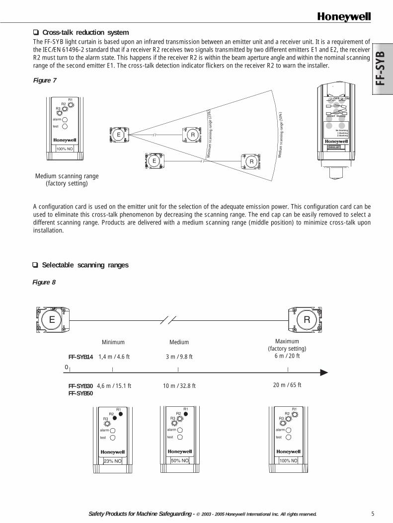
Selectable scanning ranges
Minimum
1,4 m / 4.6 ft
4,6 m / 15.1 ft
FF-SYB14
FF-SYB30FF-SYB50
0
Medium
3 m / 9.8 ft
10 m / 32.8 ft
Maximum(factory setting)
6 m / 20 ft
20 m / 65 ft
E R
R1R2
R3
alarm
test
23% NO
R1R2
R3
alarm
test
50% NO
R1R2
R3
alarm
test
100% NO
Cross-talk reduction systemThe FF-SYB light curtain is based upon an infrared transmission between an emitter unit and a receiver unit. It is a requirement ofthe IEC/EN 61496-2 standard that if a receiver R2 receives two signals transmitted by two different emitters E1 and E2, the receiverR2 must turn to the alarm state. This happens if the receiver R2 is within the beam aperture angle and within the nominal scanningrange of the second emitter E1. The cross-talk detection indicator flickers on the receiver R2 to warn the installer.
E
E
R
R
Min
imum
scan
ning
rang
e(2
3%)
Med
ium
scan
ning
rang
e(5
0%)
A configuration card is used on the emitter unit for the selection of the adequate emission power. This configuration card can beused to eliminate this cross-talk phenomenon by decreasing the scanning range. The end cap can be easily removed to select adifferent scanning range. Products are delivered with a medium scanning range (middle position) to minimize cross-talk uponinstallation.
Medium scanning range(factory setting)
No blanking1 blanking2 blanking
restart muting
OFF ON
MM2L1BP
Figure 7
Figure 8
R1R2
R3
alarm
test
100% NO
FF-SYB
6 Safety Products for Machine Safeguarding - © 2003 - 2005 Honeywell International Inc. All rights reserved.
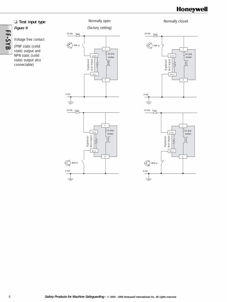
Test input typeFigure 9
Voltage free contact
(PNP static (solidstate) output andNPN static (solidstate) output alsoconnectable)
Normally open
(factory setting)
Normally closed
24 Vdc
0 Vdc
FF-SYBemitter
3
4 (-)
2 (+)
Opt
iona
lte
st in
put
1
PNP or
Fuse
NPN or
24 Vdc
0 Vdc
FF-SYBemitter
3
4 (-)
2 (+)
Opt
iona
lte
st in
put
1
Fuse 24 Vdc
0 Vdc
FF-SYBemitter
3
4 (-)
2 (+)
Opt
iona
lte
st in
put
1
Fuse
NPN or
24 Vdc
0 Vdc
FF-SYBemitter
Opt
iona
lte
st in
put
PNP or
Fuse
3
4 (-)
2 (+)
1
FF-S
YB
7Safety Products for Machine Safeguarding - © 2003 - 2005 Honeywell International Inc. All rights reserved.
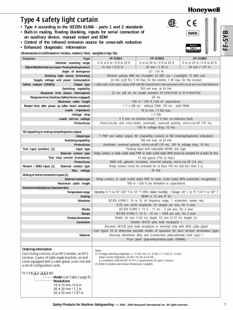
Ordering informationEach listing consists of an M12 emitter, an M12receiver, 2 pairs of right-angle brackets, an endcover equipped with a cable gland, a test rod anda set of configuration cards.
FF-SYB M2Model (see Table 2 page 9)Resolutions14: ø 14 mm / 0.6 in30: ø 30 mm / 1.2 in50: ø 50 mm / 1.97 in
Type 4 safety light curtain• Type 4 according to the IEC/EN 61496 - parts 1 and 2 standards• Built-in muting, floating blanking, inputs for serial connection of
an auxiliary device, manual restart and EDM• Control of the infrared emission source for cross-talk reduction• Enhanced diagnostic informationDimensions in millimeters / inches, meters / feet, weights in kg / lbs
Type 4per IEC/EN 61496-1/2
Approved as
Features TypeNominal scanning range
Object detection size (see chapter "Floating blanking function")
Angle of divergenceEmitting light source (immunity)
Supply voltage and power consumptionSafety outputs (OSSDs) Output type
Switching capabilityResponse time (beam interruption)
Response time (Auxiliary Safety Device engaged)Maximum cable length
Restart time after power up (after beam actuation)Loads impedance
Voltage dropLoads turn-on voltage
Protections
NC signalling or muting lamp/diagnosis outputOutput type
Switching capabilityProtections
Test input (emitter) (1) Input typeExternal contact type
Test loop current (resistance)Protections
Restart / EDM input (1) External contact typeMax. voltage
Muting or serial connection inputs (1)External contact type
Maximum cable lengthEnvironmental/physical characteristics
Temperature rangeSealing
Vibrations
ShocksBumps
Product dimensionConnection
Material
FF-SYB14 FF-SYB30 FF-SYB50 0 m to 6 m / 0 ft to 20 ft 0 m to 20 m / 0 ft to 65 ft 0 m to 20 m / 0 ft to 65 ft
14 mm / 0.55 in 30 mm / 1.18 in 50 mm / 1.97 in±2°, ±25 %
Infrared, pulsed, 880 nm (Sunlight: 20 000 Lux • Lamplight: 15 000 Lux)24 Vdc (±20 %); 5 W max. for the emitter, 5 W max. for the receiver
2 safety static (solid state) outputs (PNP with NO characteristics) with permanent short-circuit and cross-fault detections
350 mA max. at 24 Vdc22 ms (28 ms for model numbers FF-SYB14128 to FF-SYB14176)
28 ms100 m / 328 ft (100 nF capacitance)
> 1 s (80 ms - without EDM, 150 ms - with EDM)70 Ω min. / 5 kΩ max.
< 2 Vdc5 V min. on resistive loads / 7 V min. on inductive loads
Short-circuits and cross-faults, overloads, reversed polarity, micro-cut-off (10 ms,100 % voltage drop, 10 Hz)
1 PNP non safety output, NC (signalling contact) or NO (muting/diagnostic indication)100 mA max. at 24 Vdc
Overloads, reversed polarity, micro-cut-off (10 ms, 100 % voltage drop, 10 Hz)Floating input with selectable NO/NC test logic
Relay contact, or static (solid state) PNP or static (solid state) NPN (must be activated for at least 20 ms)13 mA typical (750 Ω max.)
3000 Vdc galvanic insulation, reversed polarity, micro-cut-off (14 ms)Relay contact (must be activated for at least 150 ms and less than 3 s)
29 Vdc
Relay contact, or static (solid state) PNP or static (solid state) NPN (automatic recognition)100 m / 328 ft (no limitation in capacitance)
Operating: 0 °C to 55° C/32° F to 131 °F (95% relative humidity) • Storage: -20° C to 75 °C/-4° F to 167° FNEMA 4, 13 and IP 65
IEC/EN 61496-1: 10 to 55 Hz frequency range, 1 octave/min. sweep rate,0,35 mm ±0,05 amplitude, 20 sweeps per axis, for 3 axes
IEC/EN 61496-1: 15 G - 11 ms - 3 per axis, for 3 axesIEC/EN 61496-1: 10 G - 16 ms - 1000 per axis, for 3 axes
Width: 42 mm (1.65 in); depth: 55 mm (2.16 in); height (2)Emitter: M12/5 pole male receptacle •
Receiver: M12/8 pole male receptacle or terminal strip with M20 cable gland(see Figure 10 to determine possible modes of operation for each receiver termination type)
Housing: aluminium alloy and (conductive) polycarbonate (end caps) •Front plate: polymethylmethacrylate (PMMA)
Notes:(1) Voltage switching (high/low): ≥ 11 Vdc min. (I > 6 mA) / ≤ 5 Vdc (I > 2 mA);
Input current (high/low): 20 mA / 10 mA at 24 Vdc.In compliance with the IEC 61131-2 requirements for type 2 sensors.
(2) Refer to emitter and receiver dimensions / weights.
FF-SYB
8 Safety Products for Machine Safeguarding - © 2003 - 2005 Honeywell International Inc. All rights reserved.
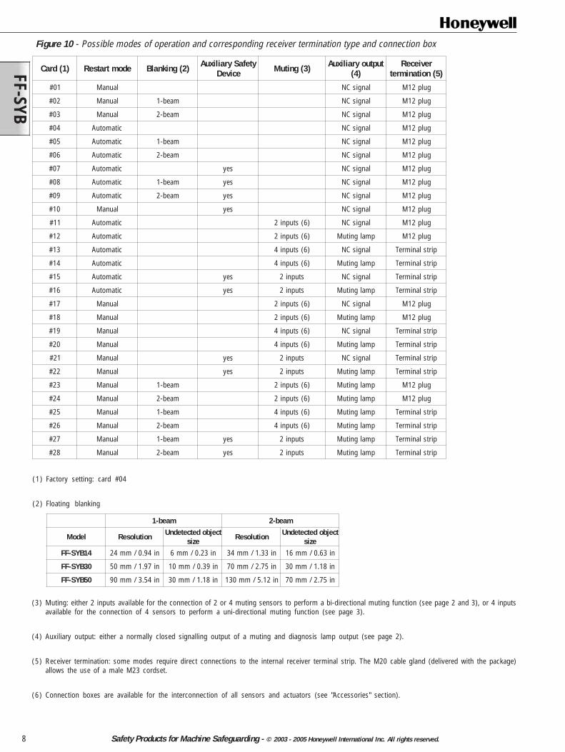
Figure 10 - Possible modes of operation and corresponding receiver termination type and connection box
)1(draC edomtratseR )2(gniknalB ytefaSyrailixuAeciveD )3(gnituM tuptuoyrailixuA
)4(revieceR
)5(noitanimret
10# launaM langisCN gulp21M
20# launaM maeb-1 langisCN gulp21M
30# launaM maeb-2 langisCN gulp21M
40# citamotuA langisCN gulp21M
50# citamotuA maeb-1 langisCN gulp21M
60# citamotuA maeb-2 langisCN gulp21M
70# citamotuA sey langisCN gulp21M
80# citamotuA maeb-1 sey langisCN gulp21M
90# citamotuA maeb-2 sey langisCN gulp21M
01# launaM sey langisCN gulp21M
11# citamotuA )6(stupni2 langisCN gulp21M
21# citamotuA )6(stupni2 pmalgnituM gulp21M
31# citamotuA )6(stupni4 langisCN pirtslanimreT
41# citamotuA )6(stupni4 pmalgnituM pirtslanimreT
51# citamotuA sey stupni2 langisCN pirtslanimreT
61# citamotuA sey stupni2 pmalgnituM pirtslanimreT
71# launaM )6(stupni2 langisCN gulp21M
81# launaM )6(stupni2 pmalgnituM gulp21M
91# launaM )6(stupni4 langisCN pirtslanimreT
02# launaM )6(stupni4 pmalgnituM pirtslanimreT
12# launaM sey stupni2 langisCN pirtslanimreT
22# launaM sey stupni2 pmalgnituM pirtslanimreT
32# launaM maeb-1 )6(stupni2 pmalgnituM gulp21M
42# launaM maeb-2 )6(stupni2 pmalgnituM gulp21M
52# launaM maeb-1 )6(stupni4 pmalgnituM pirtslanimreT
62# launaM maeb-2 )6(stupni4 pmalgnituM pirtslanimreT
72# launaM maeb-1 sey stupni2 pmalgnituM pirtslanimreT
82# launaM maeb-2 sey stupni2 pmalgnituM pirtslanimreT
(1) Factory setting: card #04
(2) Floating blanking
maeb-1 maeb-2
ledoM noituloseR tcejbodetcetednUezis noituloseR tcejbodetcetednU
ezis41BYS-FF ni49.0/mm42 ni32.0/mm6 ni33.1/mm43 ni36.0/mm61
03BYS-FF ni79.1/mm05 ni93.0/mm01 ni57.2/mm07 ni81.1/mm03
05BYS-FF ni45.3/mm09 ni81.1/mm03 ni21.5/mm031 ni57.2/mm07
(3) Muting: either 2 inputs available for the connection of 2 or 4 muting sensors to perform a bi-directional muting function (see page 2 and 3), or 4 inputsavailable for the connection of 4 sensors to perform a uni-directional muting function (see page 3).
(4) Auxiliary output: either a normally closed signalling output of a muting and diagnosis lamp output (see page 2).
(5) Receiver termination: some modes require direct connections to the internal receiver terminal strip. The M20 cable gland (delivered with the package)allows the use of a male M23 cordset.
(6) Connection boxes are available for the interconnection of all sensors and actuators (see "Accessories" section).
FF-S
YB
9Safety Products for Machine Safeguarding - © 2003 - 2005 Honeywell International Inc. All rights reserved.
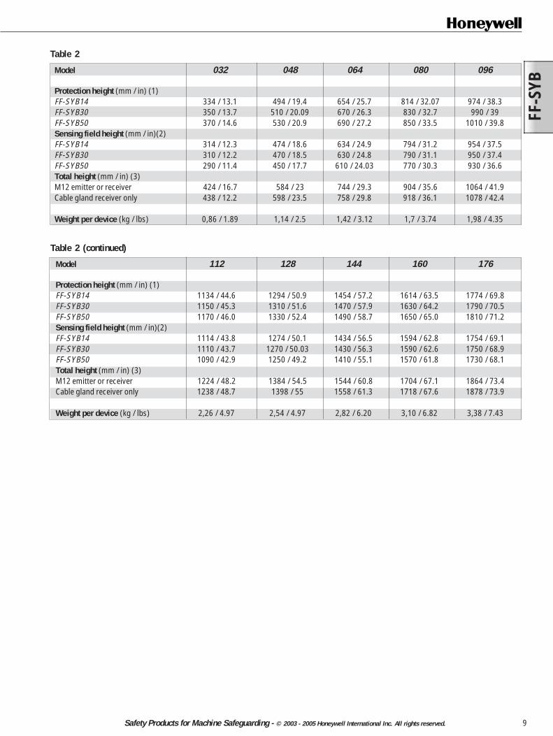
Table 2 (continued)
Model 112 128 144 160 176
Protection height (mm / in) (1)FF-SYB14 1134 / 44.6 1294 / 50.9 1454 / 57.2 1614 / 63.5 1774 / 69.8FF-SYB30 1150 / 45.3 1310 / 51.6 1470 / 57.9 1630 / 64.2 1790 / 70.5FF-SYB50 1170 / 46.0 1330 / 52.4 1490 / 58.7 1650 / 65.0 1810 / 71.2Sensing field height (mm / in)(2)FF-SYB14 1114 / 43.8 1274 / 50.1 1434 / 56.5 1594 / 62.8 1754 / 69.1FF-SYB30 1110 / 43.7 1270 / 50.03 1430 / 56.3 1590 / 62.6 1750 / 68.9FF-SYB50 1090 / 42.9 1250 / 49.2 1410 / 55.1 1570 / 61.8 1730 / 68.1Total height (mm / in) (3)M12 emitter or receiver 1224 / 48.2 1384 / 54.5 1544 / 60.8 1704 / 67.1 1864 / 73.4Cable gland receiver only 1238 / 48.7 1398 / 55 1558 / 61.3 1718 / 67.6 1878 / 73.9
Weight per device (kg / lbs) 2,26 / 4.97 2,54 / 4.97 2,82 / 6.20 3,10 / 6.82 3,38 / 7.43
Table 2
Model 032 048 064 080 096
Protection height (mm / in) (1)FF-SYB14 334 / 13.1 494 / 19.4 654 / 25.7 814 / 32.07 974 / 38.3FF-SYB30 350 / 13.7 510 / 20.09 670 / 26.3 830 / 32.7 990 / 39FF-SYB50 370 / 14.6 530 / 20.9 690 / 27.2 850 / 33.5 1010 / 39.8Sensing field height (mm / in)(2)FF-SYB14 314 / 12.3 474 / 18.6 634 / 24.9 794 / 31.2 954 / 37.5FF-SYB30 310 / 12.2 470 / 18.5 630 / 24.8 790 / 31.1 950 / 37.4FF-SYB50 290 / 11.4 450 / 17.7 610 / 24.03 770 / 30.3 930 / 36.6Total height (mm / in) (3)M12 emitter or receiver 424 / 16.7 584 / 23 744 / 29.3 904 / 35.6 1064 / 41.9Cable gland receiver only 438 / 12.2 598 / 23.5 758 / 29.8 918 / 36.1 1078 / 42.4
Weight per device (kg / lbs) 0,86 / 1.89 1,14 / 2.5 1,42 / 3.12 1,7 / 3.74 1,98 / 4.35

FF-SYB
10 Safety Products for Machine Safeguarding - © 2003 - 2005 Honeywell International Inc. All rights reserved.
M12 emitter or receiver Cable gland receiver
(1) Protection Height for the minimum detected object size or resolution(2) Sensing Field Height (full screen height)(3) Total Height (including male receptacles or cable gland)
(mm / in) øR (resolution) P (lens pitch) D (lens diameter) A (inactive zone) B (inactive zone)FF-SYB14 ø 14 / 0.6 10 / 0.4 4 / 0.16 15,2 / 0.60 90,6 / 3.56FF-SYB30 ø 30 / 1.2 20 / 0.8 10 / 0.4 22,2 / 0.87 87,6 / 3.45FF-SYB50 ø 50 / 1.97 40 / 1.57 10 / 0.39 42.2 / 1.66 87,6 / 3.45
Table 1
Figure 11 - Dimensions in mm / in
16,6 / 0.65
17,25 /0.67
Sen
sing
fiel
d he
ight
(2)
Test rod
Test rod
Tot
al h
eigh
t (3)
P
D
øR34,8/1.37
42/1.65
54,7
/2.1
5
12/0
.47
2,5/
0.09
5,6/
0.22
Pro
tect
ion
heig
ht (
1)
8,84 / 0.34
B
A
Tot
al h
eigh
t (3)
Sen
sing
fiel
d he
ight
(2)
Pro
tect
ion
heig
ht (
1)
Test rod
Test rod
FF-S
YB
11Safety Products for Machine Safeguarding - © 2003 - 2005 Honeywell International Inc. All rights reserved.
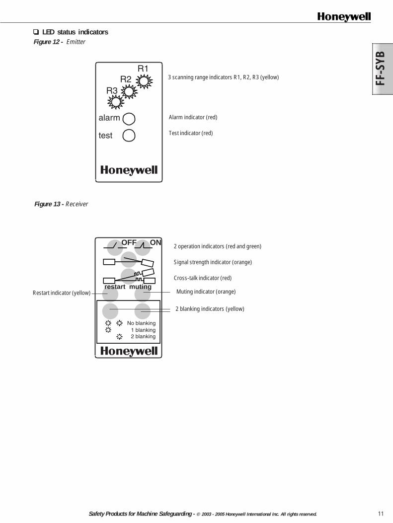
LED status indicatorsFigure 12 - Emitter
3 scanning range indicators R1, R2, R3 (yellow)
Figure 13 - Receiver
2 operation indicators (red and green)
Signal strength indicator (orange)
Cross-talk indicator (red)
No blanking1 blanking2 blanking
restart muting
OFF ON
Restart indicator (yellow)
2 blanking indicators (yellow)
Muting indicator (orange)
R1R2
R3
alarm
test
Alarm indicator (red)
Test indicator (red)
FF-SYB
12 Safety Products for Machine Safeguarding - © 2003 - 2005 Honeywell International Inc. All rights reserved.
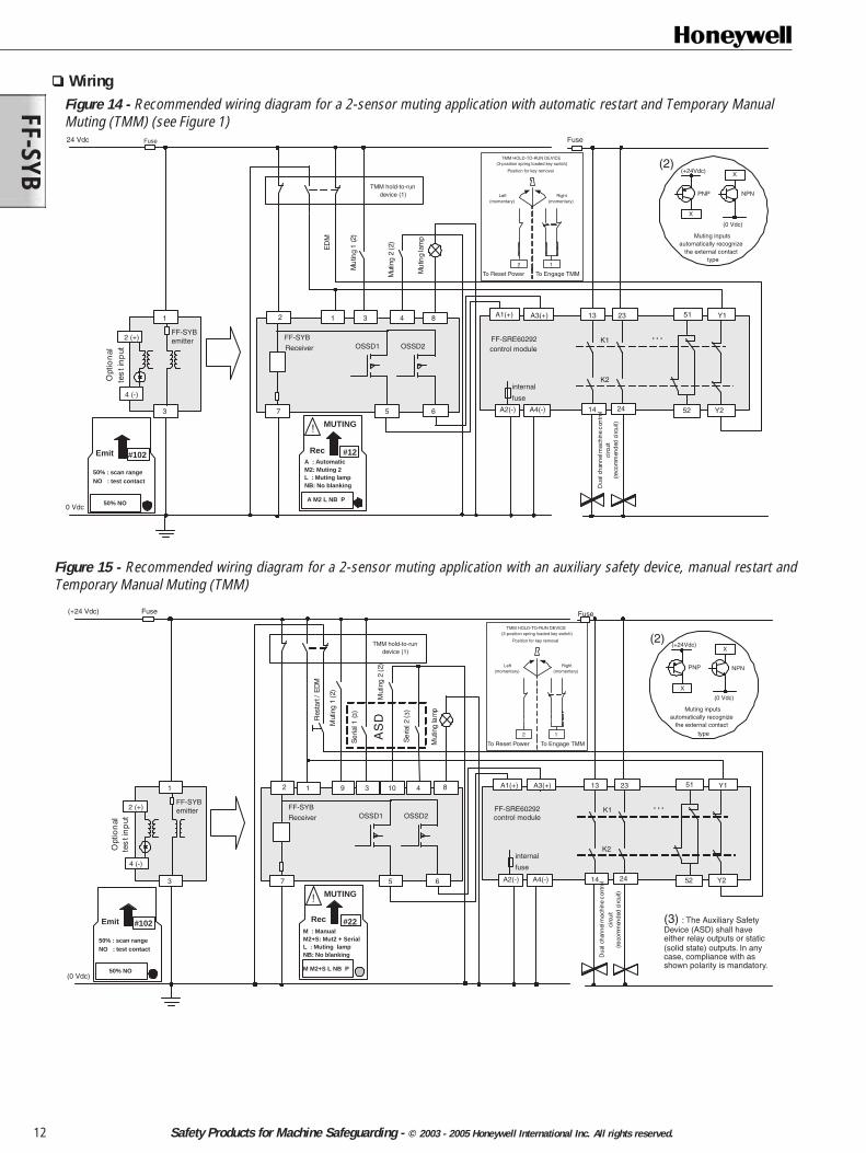
Figure 14 - Recommended wiring diagram for a 2-sensor muting application with automatic restart and Temporary ManualMuting (TMM) (see Figure 1)
Wiring
50% NO
#102Emit
50% : scan rangeNO : test contact
24 Vdc
0 Vdc
FF-SYB
Receiver
FF-SYBemitter FF-SRE60292
control moduleOSSD1 OSSD2
ED
M
Mu
ting
1 (2
)
internal
fuseM
utin
g 2
(2)
8
3 6
A3(+)
Fuse
K1
K2
13
14
Y123
24
…
52 Y2
Dua
l cha
nnel
mac
hine
con
trol
circ
uit
(reco
mm
ende
d ci
rcui
t)
51
4 (-)
2 (+)
Opt
ion
alte
st i
np
ut
A2(-) A4(-)
1 3 41
7
2 A1(+)
5
Fuse
Mu
ting
lam
p Muting inputsautomatically recognize
the external contacttype
(+24Vdc)
(0 Vdc)
(2)
PNP NPN
X
X
TMM hold-to-rundevice (1)
A : AutomaticM2: Muting 2L : Muting lampNB: No blanking
A M2 L NB P
MUTING
#12
!
Rec
12
Right(momentary)
Left(momentary)
Position for key removal
To Reset Power To Engage TMM
TMM HOLD-TO-RUN DEVICE(3-position spring loaded key switch)
50% NO
#102Emit
50% : scan rangeNO : test contact
(+24 Vdc)
(0 Vdc)
FF-SYB
Receiver
FF-SYBemitter FF-SRE60292
control moduleOSSD1 OSSD2
Fuse
internal
fuse
3 5 6
A3(+)
Fuse
K1
K2
13
14
Y123
24
…
52
Dua
l cha
nnel
mac
hine
con
trol
circ
uit
(reco
mm
ende
d ci
rcui
t)
51
4 (-)
2 (+)
Opt
ion
alte
st i
np
ut
A2(-) A4(-)
11
7
2
M : ManualM2+S: Mut2 + SerialL : Muting lampNB: No blanking
M M2+S L NB P
MUTING
#22
!
Rec
8
Res
tart
/ E
DM
Mut
ing
1(2
)
9
Se
rial 1
(3)
3
Mut
ing
2 (2
)
10
Se
rial 2
(3)
4
Y2
Mut
ing
lam
p Muting inputsautomatically recognize
the external contacttype
(+24Vdc)
(0 Vdc)
(2)
PNP NPN
X
X
AS
D
TMM hold-to-rundevice (1)
(3) : The Auxiliary SafetyDevice (ASD) shall haveeither relay outputs or static(solid state) outputs. In anycase, compliance with asshown polarity is mandatory.
A1(+)
12
Right(momentary)
Left(momentary)
Position for key removal
To Reset Power To Engage TMM
TMM HOLD-TO-RUN DEVICE(3-position spring loaded key switch)
Figure 15 - Recommended wiring diagram for a 2-sensor muting application with an auxiliary safety device, manual restart andTemporary Manual Muting (TMM)
FF-S
YB
13Safety Products for Machine Safeguarding - © 2003 - 2005 Honeywell International Inc. All rights reserved.
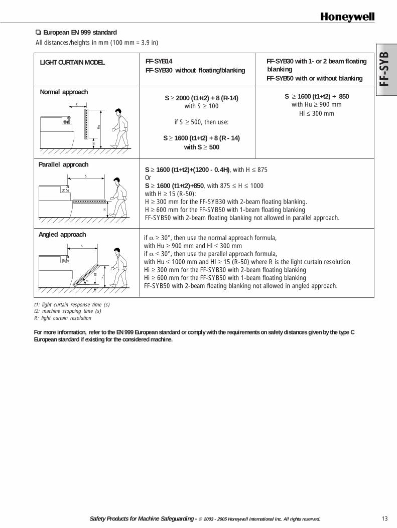
European EN 999 standardAll distances/heights in mm (100 mm = 3.9 in)
FF-SYB14FF-SYB30 without floating/blanking
S ≥ 2000 (t1+t2) + 8 (R-14)with S ≥ 100
if S ≥ 500, then use:
S ≥ 1600 (t1+t2) + 8 (R - 14)with S ≥ 500
FF-SYB30 with 1- or 2 beam floatingblankingFF-SYB50 with or without blanking
S ≥ 1600 (t1+t2) + 850with Hu ≥ 900 mm
Hl ≤ 300 mm
LIGHT CURTAIN MODEL
S ≥ 1600 (t1+t2)+(1200 - 0.4H), with H ≤ 875OrS ≥ 1600 (t1+t2)+850, with 875 ≤ H ≤ 1000with H ≥ 15 (R-50):H ≥ 300 mm for the FF-SYB30 with 2-beam floating blanking.H ≥ 600 mm for the FF-SYB50 with 1-beam floating blankingFF-SYB50 with 2-beam floating blanking not allowed in parallel approach.
S
HlHu
S
H
S
Hu
Hl
Angled approach
Parallel approach
Normal approach
t1: light curtain response time (s)t2: machine stopping time (s)R: light curtain resolution
For more information, refer to the EN 999 European standard or comply with the requirements on safety distances given by the type CEuropean standard if existing for the considered machine.
if α ≥ 30°, then use the normal approach formula,with Hu ≥ 900 mm and Hl ≤ 300 mmif α ≤ 30°, then use the parallel approach formula,with Hu ≤ 1000 mm and Hl ≥ 15 (R-50) where R is the light curtain resolutionHi ≥ 300 mm for the FF-SYB30 with 2-beam floating blankingHi ≥ 600 mm for the FF-SYB50 with 1-beam floating blankingFF-SYB50 with 2-beam floating blanking not allowed in angled approach.
FF-SYB
14 Safety Products for Machine Safeguarding - © 2003 - 2005 Honeywell International Inc. All rights reserved.
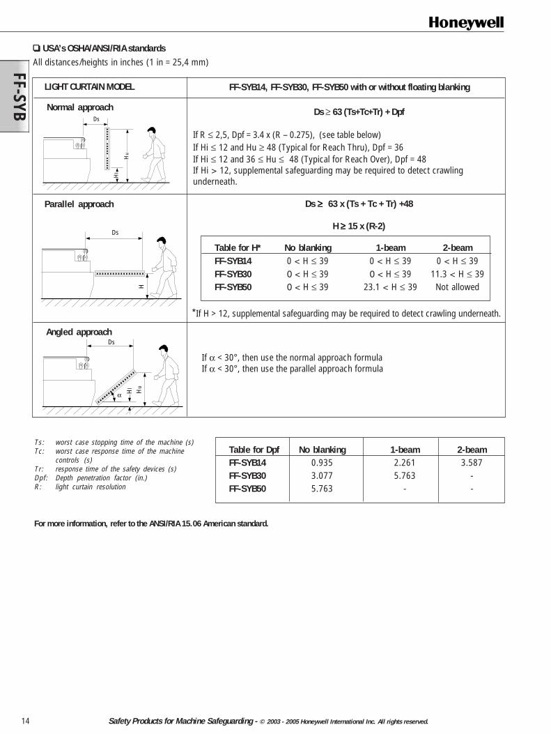
USA’s OSHA/ANSI/RIA standardsAll distances/heights in inches (1 in = 25,4 mm)
LIGHT CURTAIN MODEL
Ds ≥ 63 (Ts+Tc+Tr) + Dpf
If R ≤ 2,5, Dpf = 3.4 x (R – 0.275), (see table below)If Hi ≤ 12 and Hu ≥ 48 (Typical for Reach Thru), Dpf = 36If Hi ≤ 12 and 36 ≤ Hu ≤ 48 (Typical for Reach Over), Dpf = 48If Hi > 12, supplemental safeguarding may be required to detect crawlingunderneath.
Ds ≥≥≥≥≥ 63 x (Ts + Tc + Tr) +48
H ≥ ≥ ≥ ≥ ≥ 15 x (R-2)
Angled approach
Parallel approach
Hu
Hl
Ds
Ds
H
Ds
α Hl
Hu
For more information, refer to the ANSI/RIA 15.06 American standard.
Table for Dpf No blanking 1-beam 2-beamFF-SYB14 0.935 2.261 3.587FF-SYB30 3.077 5.763 -FF-SYB50 5.763 - -
Normal approach
FF-SYB14, FF-SYB30, FF-SYB50 with or without floating blanking
Table for H* No blanking 1-beam 2-beamFF-SYB14 0 < H ≤ 39 0 < H ≤ 39 0 < H ≤ 39FF-SYB30 0 < H ≤ 39 0 < H ≤ 39 11.3 < H ≤ 39FF-SYB50 0 < H ≤ 39 23.1 < H ≤ 39 Not allowed
If α < 30°, then use the normal approach formulaIf α < 30°, then use the parallel approach formula
*If H > 12, supplemental safeguarding may be required to detect crawling underneath.
Ts: worst case stopping time of the machine (s)Tc: worst case response time of the machine
controls (s)Tr: response time of the safety devices (s)Dpf: Depth penetration factor (in.)R: light curtain resolution

FF-S
YB
15Safety Products for Machine Safeguarding - © 2003 - 2005 Honeywell International Inc. All rights reserved.
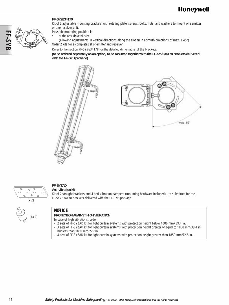
Accessories FF-SYZ634178Kit of 2 right angle mounting brackets with screws, bolts, nuts and washers to mount one emitter or one receiver unit.Possible mounting positions:1. At the top and the bottom of the FF-SYB (allowing adjustments in azimuth directions of ±10°).2. At one of the two lateral dovetail slots (allowing adjustments in vertical directions along the slot)3. At the rear dovetail slot (allowing adjustments in vertical directions along the slot)Order 2 kits for a complete set of emitter and receiver.(already included in the FF-SYB package)
ø5,5/0.21
15/0.59 5/
0.19
23,5/0.19
11,5
/0.4
5
33 / 1.30 33,8 / 1.33
ø5,51 / 0.21
52,2 / 2.05
35 /
1.37
R23
R2
37˚
55 /
2.16
38 /
1.49
25 /
0.98
2,5
/ 0.0
9
90˚
Bracket mounting at the top and the bottom Bracket mounting at the lateral dovetail slots
54/2.12
10˚ 10˚
Bracket mounting at the rear dovetail slots
20 / 0.78
1,5 / 0.06
9,66 / 0.38
M5
ø5,
2 / 0
.20
16,7
/ 0.
65
2,4
/ 0.0
9
M5 dovetail shape bolt
12/0.47
24,45 / 0.96
FF-SYB
16 Safety Products for Machine Safeguarding - © 2003 - 2005 Honeywell International Inc. All rights reserved.
FF-SYZADAnti-vibration kitKit of 2 straight brackets and 4 anti-vibration dampers (mounting hardware included) - to substitute for theFF-SYZ634178 brackets delivered with the FF-SYB package.
NOTICENOTICENOTICENOTICENOTICEPROTECTION AGAINST HIGH VIBRATIONIn case of high vibrations, order:- 2 sets of FF-SYZAD kit for light curtain systems with protection height below 1000 mm/ 39.4 in.- 3 sets of FF-SYZAD kit for light curtain systems with protection height greater or equal to 1000 mm/39.4 in,
but less than 1850 mm/72.8in.- 4 sets of FF-SYZAD kit for light curtain systems with protection height greater than 1850 mm/72.8 in.
FF-SYZ634179Kit of 2 adjustable mounting brackets with rotating plate, screws, bolts, nuts, and washers to mount one emitteror one receiver unit.Possible mounting position is:• at the rear dovetail slot
(allowing adjustments in vertical directions along the slot an in azimuth directions of max. ± 45°)Order 2 kits for a complete set of emitter and receiver.Refer to the section FF-SYZ634178 for the detailed dimensions of the brackets.(to be ordered separately as an option, to be mounted together with the FF-SYZ634178 brackets deliveredwith the FF-SYB package)
(x 2)
(x 4)
FF-S
YB
17Safety Products for Machine Safeguarding - © 2003 - 2005 Honeywell International Inc. All rights reserved.
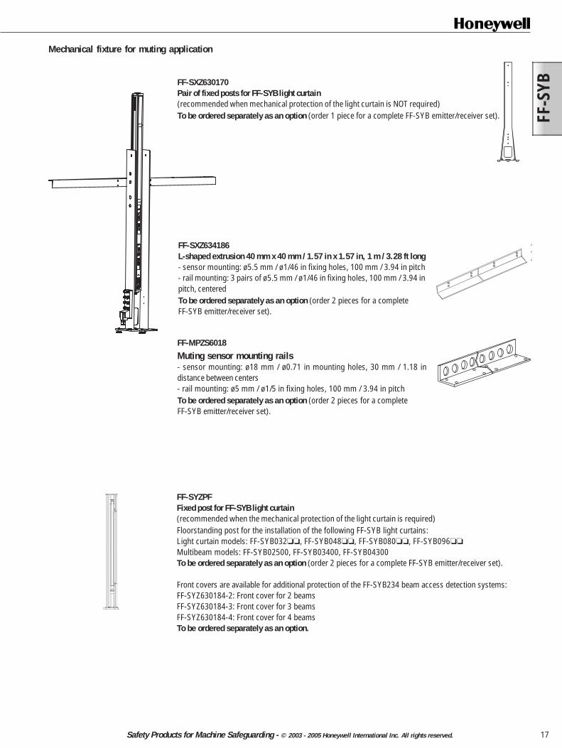
FF-SYZPFFixed post for FF-SYB light curtain(recommended when the mechanical protection of the light curtain is required)Floorstanding post for the installation of the following FF-SYB light curtains:Light curtain models: FF-SYB032, FF-SYB048, FF-SYB080, FF-SYB096
Multibeam models: FF-SYB02500, FF-SYB03400, FF-SYB04300To be ordered separately as an option (order 2 pieces for a complete FF-SYB emitter/receiver set).
Front covers are available for additional protection of the FF-SYB234 beam access detection systems:FF-SYZ630184-2: Front cover for 2 beamsFF-SYZ630184-3: Front cover for 3 beamsFF-SYZ630184-4: Front cover for 4 beamsTo be ordered separately as an option.
FF-SXZ630170Pair of fixed posts for FF-SYB light curtain(recommended when mechanical protection of the light curtain is NOT required)To be ordered separately as an option (order 1 piece for a complete FF-SYB emitter/receiver set).
FF-MPZS6018
Muting sensor mounting rails- sensor mounting: ø18 mm / ø0.71 in mounting holes, 30 mm / 1.18 indistance between centers- rail mounting: ø5 mm / ø1/5 in fixing holes, 100 mm / 3.94 in pitchTo be ordered separately as an option (order 2 pieces for a completeFF-SYB emitter/receiver set).
Mechanical fixture for muting application
FF-SXZ634186L-shaped extrusion 40 mm x 40 mm / 1.57 in x 1.57 in, 1 m / 3.28 ft long- sensor mounting: ø5.5 mm / ø1/46 in fixing holes, 100 mm / 3.94 in pitch- rail mounting: 3 pairs of ø5.5 mm / ø1/46 in fixing holes, 100 mm / 3.94 inpitch, centeredTo be ordered separately as an option (order 2 pieces for a completeFF-SYB emitter/receiver set).

FF-SYB
18 Safety Products for Machine Safeguarding - © 2003 - 2005 Honeywell International Inc. All rights reserved.
FF-SYZPFMFixed post with plain mirror (10 % or 25 % reduction of scanning range)Floorstanding post with 1 plain mirror (FF-SYZPFM01,10 % of loss)Floorstanding post with 1 plain mirror (FF-SYZPFM11, 25 % of loss)Suitable for light curtain models: FF-SYB032, FF-SYB048, FF-SYB080, FF-SYB096
To be ordered separately as an option.
FF-SXZSHLIP67 enclosure for FF-SYB light curtains
Enclosures Light curtainsFF-SXZSHL048 FF-SYB 032 and 048FF-SXZSHL096 FF-SYB 064 through 096FF-SXZSHL128 FF-SYB 112 and 128FF-SXZSHLKIT Brackets and cable gland kit (order one kit per enclosure)
: "P" for polycarbonate, "G" for glass
FF-SYZMIR Deflection mirrorTo be ordered separately as an option
Features:Deflection mirror with 10 % scanning range reduction (FF-SYZMIR004 through 18)Deflection mirror with 25 % scanning range reduction (FF-SYZMIR104 through 18)Food and Beverage industry: stainless steel deflection mirrors with 45 % scanning rangereduction (FF-SYZMIR204 through 14)Quick mounting and easy mirror adjustmentMounting brackets included (top / bottom mounting)Adjustment of mirror in azimuth direction of ±45°Material Aluminium alloy housingFinish Gold colour anodisation
Ordering guide:FF-SYZMIR04FF-SYZMIR06FF-SYZMIR08
FF-SYZMIR10FF-SYZMIR12FF-SYZMIR14FF-SYZMIR16FF-SYZMIR18
FF-SY032 and FF-SY048FF-SY064FF-SY080FF-SY096FF-SY112 and FF-SY128FF-SY144FF-SY160FF-SY176
FF-SYZPAAdjustable floor standing post- Compatible with all protection heights- Horizontal, diagonal and vertical adjustment of light curtains possible- Quick mounting and easy light curtain adjustment- 360° rotation of light curtain possible- Fine adjustment of light curtains in azimuth direction of ±11° ensures an easy alignment- 700 mm / 27.58 in corner protection for light curtain included- Base plate can be mounted independently- Finish: RAL 1021 yellow paintTo be ordered separately as an option.

FF-S
YB
19Safety Products for Machine Safeguarding - © 2003 - 2005 Honeywell International Inc. All rights reserved.
M12 connection boxesFor the connection of muting sensors, restart and TMM switches and muting lamp to thelight curtain
FF-SXZBOX8M12TIP67 junction box, field-attachable home run cable, M12 8-port configuration.
FF-SXZBOX8M12L02IP67 junction box, field-attachable home run cable, M12 8-port configuration, prewiredwith a 2 m/6.56 ft M12 8-pin cordset.
CordsetsM12/5 pole
M12 single-ended cordset, female / 5-pin straight for the FF-SYB emitterFF-SXZCAM125U02 2 m / 6.56 ft lengthFF-SXZCAM125U05 5 m / 16.40 ft lengthFF-SXZCAM125U10 10 m / 32.8 ft lengthEquivalent to the 805000A09M... Micro-change® Series from Brad Harrison(see vendor catalog for color code)
M12/8 poleM12 single-ended cordset, female / 8-pin straight for the FF-SYB receiverFF-SXZCAM128U02 2 m / 6.56 ft lengthFF-SXZCAM128U05 5 m / 16.40 ft lengthFF-SXZCAM128U10 10 m / 32.8 ft lengthEquivalent to the 808000P02M... Micro-change® Series from Brad Harrison(see vendor catalog for color code)
1: white2: brown3: green4: yellow5: grey6: pink7: blue8: red
1: brown2: white3: blue4: black5: green/yellow
Cable connectorFF-SXZCOM125 - M12 screw connector, female / 5 pin straight for the FF-SYB emitterFF-SXZCOM128 - M12 screw connector, female / 8 pin straight for the FF-SYB receiver
Safety control modulesFF-SRE60292Slim line expansion module- 24 Vdc- Safety interface up to Category 4 per EN 954-1- 4 NO/2 NC safety relay outputs- 22,5 mm / 0.88 in width(to be ordered separately as an option).
FF-SRE30812Expansion module- 24 Vdc, 115 Vac or 230 Vac- Safety interface up to Category 4 per EN 954-1- 7 NO/1 NC internally redundant safety relay outputs- 90 mm / 3.54 in width(to be ordered separately as an option).

FF-SYB
20 Safety Products for Machine Safeguarding - © 2003 - 2005 Honeywell International Inc. All rights reserved.
(not contractual)
45 mm / 1.77 in.
97 mm / 3
.82 in.
91 mm / 3
.58 in.
20 m
m /
0.79
in.
20 m
m /
0.79
in.
35 m
m /
1.38
in.
75 m
m /
2.95
in.
(not contractual)
ac to dc power supply FF-SXZPWR050ac to dc power supply(to be ordered separately as an option)- Approvals: UL508 listed, UL1950, cUL/CSA-C22.2 No.950-M90, EN/IEC 60950,
EN 50178 (Class 2 Rated for low power installations)- Input voltage: 85-264 Vac (43-67 Hz)- Output voltage: 24-28 Vdc adjustable- Rated continuous load (at 60 °C/140 °F max.): 2,1 A @ 24 Vdc / 1,8A @ 28 Vdc- Power: 50 W- Dimensions 75 mm x 45 mm x 97 mm / 2.95 in x 1.77 in x 3.82 in- DIN rail mounting- Weight: 240 g / 0.52 lbs
Muting lamp FF-SXZMLEDBeacon supplied with fixing plate for vertical surface and a LEDs bulb(Telemecanique XVB Series type). To be used as the muting/diagnostic lamp.
3 position spring loaded key switch FF-SXZTMMø 22 mm 3-position spring loaded key switch with a Normally Closed contact on the leftposition and two complementary (Normally Closed and Normally Open) contacts on the rightposition (Telemecanique ZB5 Series type, fixing collar with screw clamp contact blocks,key # 455).To be used as the TMM hold-to-run device.
Safety control modulesFF-SRM200P2Mutual exclusion module(to be ordered separately as an option)- typical applications: loading/unloading chamber on machining centers or conveyors,
crossing of conveyor lines, moving conveyors or AGVs- connection of 2 safety devices- 24 Vdc- Category 4 per EN 954-1- manual start mode, FSD monitoring- crossfault monitoring of inputs- 3 NO safety relay outputs- static outputs for output status and diagnostic information- 45 mm / 1.77 in
FF-SRL59022Presence Sensing Device Initiation (PSDI)(to be ordered separately as an option).- to be used with FF-SYB14 or FF-SYB30 only- accept a single safety light curtain working in a single stroke/dual stroke mode- 24 Vdc- Category 4 per EN 954-1- manual start mode and FSD monitoring- cross-fault monitoring of inputs- 3 NO safety relay outputs- static outputs for relay output status and diagnostic information- 45 mm / 1.77 in

FF-S
YB
21Safety Products for Machine Safeguarding - © 2003 - 2005 Honeywell International Inc. All rights reserved.
FF-SPZLASERThe laser pen FF-SPZLASER is a self-contained and compact laser device designed to ease infraredbeam alignments. Its class II conforms to the EN 60825 European standard and the US 21 CFR 1040American standard.To be ordered separately as an option.
FF-SYZ604795Mechanical adapter for the FF-SPZLASER laser pen to be used with the FF-SYB Series light curtain.To be ordered separately as an option.
Test rods FF-SYZROD14Test rod for ø14 mm / 0.6 in resolution safety light curtains(already included in the FF-SYB package).
FF-SBZROD30Test rod for ø30 mm / 1.2 in resolution safety light curtains(already included in the FF-SYB package).
Configuration cards FF-SYZ101085RSet of 28 configuration cards for FF-SYB receiver
FF-SYZ101092ESet of 6 configuration cards for FF-SYB emitter
Installation manuals FF-PK107120-EN One FF-SYB English installation manualFF-PK107120-DE One FF-SYB German installation manualFF-PK107120-FR One FF-SYB French installation manualFF-PK107120-IT One FF-SYB Italian installation manualFF-PK107120-SP One FF-SYB Spanish installation manual
NOTICENOTICENOTICENOTICENOTICEBy default, products will be shipped with the installation manual in the language of the country of delivery when available or in English. If any otherlanguage is required, it must be ordered separately.

Warranty and remedyHoneywell warrants goods of its manufacture as being free of defectivematerials and faulty workmanship. Contact your local sales office for war-ranty information. If warranted goods are returned to Honeywell duringthe period of coverage, Honeywell will repair or replace without chargethose items it finds defective. The foregoing is Buyer’s sole remedy andis in lieu of all other warranties, expressed or implied, including thoseof merchantability and fitness for a particular purpose.While we provide application assistance, personally, through our literatureand the Honeywell web site, it is up to the customer to determine thesuitability of the product in the application.
Honeywell21 Chemin du Vieux Chêne38240 Meylan CedexFrance
This publication does not constitute a contract between Honeywell and its customers. The contents may be changed at any time without notice. It is thecustomer's responsibility to ensure safe installation and operation of the products. Detailed mounting drawings of all products illustrated are available onrequest. © 2003 - 2005 Honeywell International Inc. All rights reserved.
Specifications may change at any time without notice. The information wesupply is believed to be accurate and reliable as of this printing. However,we assume no responsibility for its use.
Sales and ServiceHoneywell serves its customers through a worldwide network of salesoffices and distributors. For application assistance,current specifications,pricing or name of the nearest Authorised Distributor, contact a nearbysales office or:INTERNET: www.honeywell.com/sensing
E-mail: [email protected]
www.honeywell.com/sensing
ASIA PACIFIC
Control ProductsAsia Pacific HeadquartersPhone: +(65) 6355-2828Fax: +(65) 6445-3033
AustraliaHoneywell LimitedPhone: +(61) 2-9370-4500Fax: +(61) 2-9370-4525Toll Free 1300-36-39-36Toll Free Fax: 1300-36-04-70
China - PRC - BeijingHoneywell China Inc.Phone: +(86-10) 8458-3280Fax: +(86-10) 8458-3102
China - PRC - ShanghaiHoneywell China Inc.Phone: (86-21) 6237-0237Fax: (86-21) 6237-1237
China - Hong Kong S.A.R.Honeywell Ltd.Phone: +(852) 2953-6412Fax: +(852) 2953-6767
IndonesiaHoneywell Indonesia Pte Ltd.Phone: +(62) 21-535-8833Fax: +(62) 21-5367-1008
IndiaTATA Honeywell Ltd.Phone: +(91) 20 687 0445/0446Fax: +(91) 20 681 2243/6875992
JapanHoneywell IncPhone: +(81) 3 5440 1425Fax: +(81) 3 5440 1368
South KoreaHoneywell Korea Co LtdPhone: +(822) 799-6167Fax: +(822) 792-9013
MalaysiaHoneywell Engineering Sdn BhdPhone: +(60-3) 7958-4988Fax: +(60-3) 7958-8922
New ZealandHoneywell LimitedPhone: +(64-9) 623-5050Fax: +(64-9) 623-5060Toll Free (0800) 202-088
PhilippinesHoneywell Systems (Philippines) Inc.Phone: +(63-2) 636-1661/1662Fax: +(63-2) 638-4013
SingaporeHoneywell South East AsiaPhone: +(65) 6355-2828Fax: +(65) 6445-3033
ThailandHoneywell Systems (Thailand) Ltd.Phone: +(662) 693-3099Fax: +(662) 693-3085
Taiwan R.O.C.Honeywell Taiwan Ltd.Phone: +(886-2) 2245-1000Fax: +(886-2) 2245-3242
EUROPE
AustriaHoneywell Austria GmbHPhone: +(43) 1 727 80 366/246Fax: +(43) 1 727 80 337
BelgiumHoneywell SA/NVPhone: +(32) 2 728 2522Fax: +(32) 2 728 2502
BulgariaHoneywell EOODPhone: +(359) 2 979 00 23Fax: +(359) 2 979 00 24
Czech RepublicHoneywell spol. s.r.o.Phone: +(420) 242 442 111Fax: +(420) 242 442 182
DenmarkHoneywell A/SPhone: +(45) 39 55 55 55Fax: +(45) 39 55 55 58
FinlandHoneywell OYPhone: +(358) 9 3480101Fax: +(358) 9 34801375
FranceHoneywell SAPhone: +(33) 1 60 19 80 40Fax: +(33) 1 60 19 81 73
GermanyHoneywell AGPhone: +(49) 69 8064 444Fax: +(49) 69 8064 442
HungaryHoneywell Kft.Phone: +(36 1) 451 4300Fax: +(36 1) 451 4343
ItalyHoneywell S.p.A.Phone: +(39) 02 92146 450/456Fax: +(39) 02 92146 490
The NetherlandsHoneywell B.V.Phone: +(31) 20 565 69 11Fax: +(31) 20 565 66 00
NorwayHoneywell A/SPhone: +(47) 66 76 20 00Fax: +(47) 66 76 20 90
PolandHoneywell Sp. zo.oPhone: +(48)606 0964Fax: +(48)606 0901
PortugalHoneywell Portugal LdaPhone: +(351 21) 424 50 00Fax: +(351 21) 424 50 99
RomaniaHoneywell BucharestPhone: +(40) 21 231 64 37/38Fax: +(40) 21 231 6439
Commonwealth ofIndependent States (CIS)Z.A.O. HoneywellPhone: +(7 095) 796 98 36Fax: +(7 095) 796 98 93
Slovak RepublicHoneywell s.r.o.Phone: +(421 2) 58 247 403Fax: +(421 2) 58 247 415
LATIN AMERICA
Honeywell Latin AmericaHeadquartersPhone: 1-305-805-8188Fax: 1-305-883-8257
ArgentinaHoneywell S.A.I.C.Phone: +(54-11) 4383-3637Fax: +(54-11) 4325-6470
BrazilHoneywell do Brasil & CiaPhone: +(55-11) 4166-1900Fax: +(55-11) 4166-1901
ChileHoneywell Chile, S.A.Phone: +(56-2) 425-8400Fax: +(56-2) 425-8410
MexicoHoneywell S.A. de C.V.Phone: +(52) 55 5081-0200Fax: +(52) 55 5081-0202
Puerto Rico, CaribbeanHoneywell Inc.Phone: +(809) 792-7075Fax: +(809) 792-0053
VenezuelaHoneywell CAPhone: +(58-212) 273-0511Fax: +(58-212) 273-0599
South Africa (Republic of)Honeywell Southern AfricaHoneywell S.A. Pty. LtdPhone: +(27) 11 805 1201Fax: +(27) 11 805 1504
SpainHoneywell S.A.Phone: +(34) 91 313 6100Fax: +(34) 91 313 6129
SwedenHoneywell ABPhone: +(46) 8 775 55 00Fax: +(46) 8 775 56 00
SwitzerlandHoneywell AGPhone: +(41) 1 855 24 40Fax: +(41) 1 855 24 45
TurkeyHoneywell Turkey A.S.Phone: +(90) 216 575 6620Fax: +(90) 216 575 6637
UkraineHoneywellPhone: +(380) 44 201 44 74Fax: +(380) 44 201 44 75
United KingdomHoneywell Control Systems LtdPhone: +(44) 1698 481481Fax: +(44) 1698 481676
Mediterranean & AfricanDistributorsHoneywell SpAPhone: +(39) 2 921 46 232Fax: +(39) 2 921 46 233
Middle East HeadquartersHoneywell Middle East Ltd.Phone: +(9712) 443 2119Fax: +(9712) 443 2536
NORTH AMERICA
USA/CanadaHoneywellSensing and ControlPhone: 1-800-537-69451-815-235-6847Fax: 1-815-235-6545E-mail: [email protected]
107119-20-EN FR26 GLO 405 Printed in France