Embed Size (px)
Citation preview

FF Physical Layer ComponentsBest PracticesBest Practices
Binoy KamathAGM – Project Pursuit
© 2011 Fieldbus Foundation
jPepperl+Fuchs India Pvt. LTd.,Bangalore

AgendaAgenda
Introduction to FF and FF Physical Layery yFF Physical Layer Components FF Wiring Topologiesg p gFF Segment DesignFF Monitoring and DiagnosisFF Monitoring and DiagnosisSummary and Conclusion
© 2011 Fieldbus Foundation

AG181 REVISION 3.1 Official FF Design GuidelinesAG181 REVISION 3.1 Official FF Design Guidelines
© 2011 Fieldbus Foundation
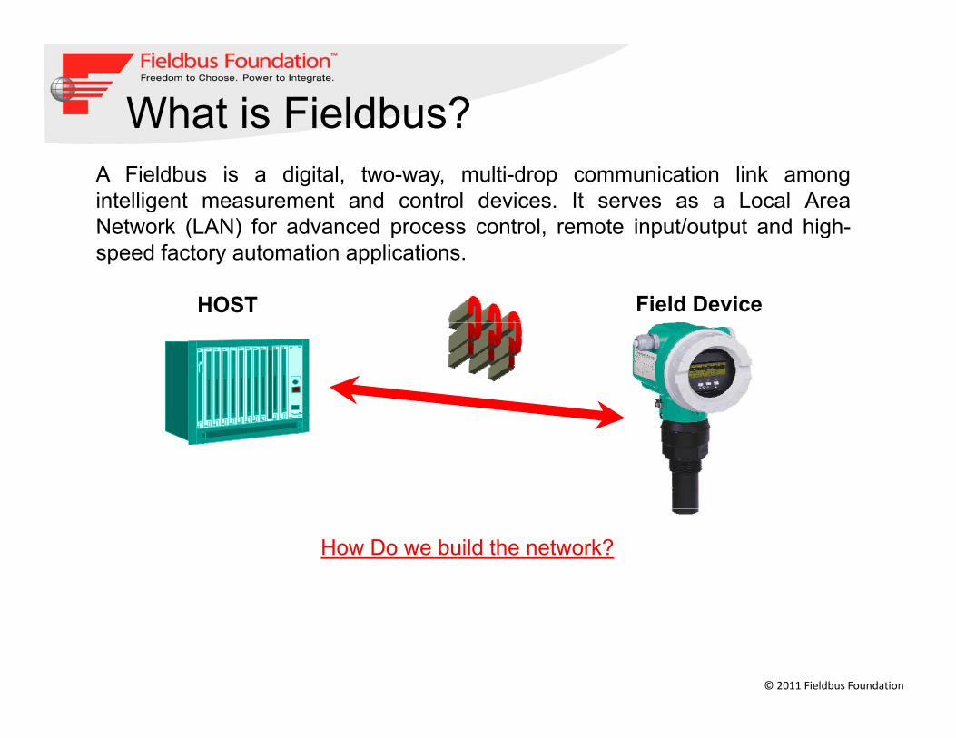
What is Fieldbus?A Fieldbus is a digital, two-way, multi-drop communication link amongintelligent measurement and control devices. It serves as a Local AreaNetwork (LAN) for advanced process control remote input/output and high-Network (LAN) for advanced process control, remote input/output and highspeed factory automation applications.
HOST Field Device
How Do we build the network?
© 2011 Fieldbus Foundation

Physical Layer Components y y p
HOST
Wiring BlockWiring Block FIELDBUS
TERMINATORFf POWER S
JUNCTION BOXSUPPLY BOX
Spurs
SURGE PROTECTOR
PROCESSINTERFACE
Home Run Spurs
CONVENTIONAL FIELD DEVICES
FIELDBUS DEVICES
© 2011 Fieldbus Foundation

Physical Layer and Its Components
The Physical Layer receives messages from the CommunicationsStack and converts the messages into physical signals on thefieldbus transmission medium, and vice-versa.
FF Power SupplyFF Power SupplyFF Cables FF Wiring BlocksFF Surge ProtectorFF Terminators
© 2011 Fieldbus Foundation

FF Power SupplyFOUNDATION Fieldbus Power Supplies (6.2.2 – AG 181 v3.1)
FOUNDATION fieldbus power supplies are specialized power suppliesFOUNDATION fieldbus power supplies are specialized power suppliesthat provide both the segment isolation from bulk power and thepower conditioner in one unit.
Power conditioning prevents the bulk power supply from shorting outPower conditioning prevents the bulk power supply from shorting outthe communications signal, preventing the segment from functioning.
Isolation prevents ground loops and interference among segments.
They shall have the appropriate approval: FF-831 “FOUNDATIONSpecification; Fieldbus Power Supply Test Specification” andassociated check mark
FOUNDATION fieldbus power supplies should be redundant, loadsharing and output current limiting, and provide facilities formonitoring faults and failures. .
© 2011 Fieldbus Foundation

FF Power Supply – General Purpose and With DCS System ConnectorsSystem Connectors
APPROVEDAPPROVED
© 2011 Fieldbus Foundation

FF Power Supply – Recommendations pp y
Each Segment shall have a dedicated FFPSFFPS shall be modular and hot SwappableFFPS shall be Isolated, Redundant and Load SharingFFPS shall provide facilities for monitoring faultsand failuresand failuresFFPS rating shall allow longer home run / Trunklength to benefit user
© 2011 Fieldbus Foundation

FF Wiring BlocksFF Wiring Blocks
© 2011 Fieldbus Foundation
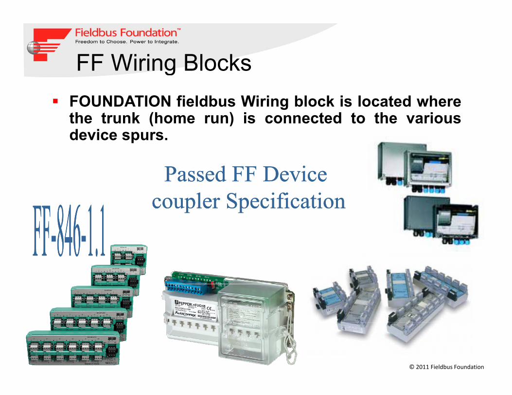
FF Wiring Blocks gFOUNDATION fieldbus Wiring block is located wherethe trunk (home run) is connected to the variousthe trunk (home run) is connected to the variousdevice spurs.
© 2011 Fieldbus Foundation

FF Wiring Blocks - SummaryOnly registered FOUNDATION fieldbus Wiring blocks shall beused
g y
The couplers shall have built-in spur short-circuit protection (tominimize the impact of a short at one device affecting the wholesegment)segment)
Spur short-circuit protection shall have visual indication (on aspur level) when short-circuit protection is active and thespur level) when short circuit protection is active and thespur's maximum current shall be limited by area classificationand the current available to the network
The couplers should provide visual indication of segmentpower as a minimum
© 2011 Fieldbus Foundation

FF CablesFF Cables
© 2011 Fieldbus Foundation
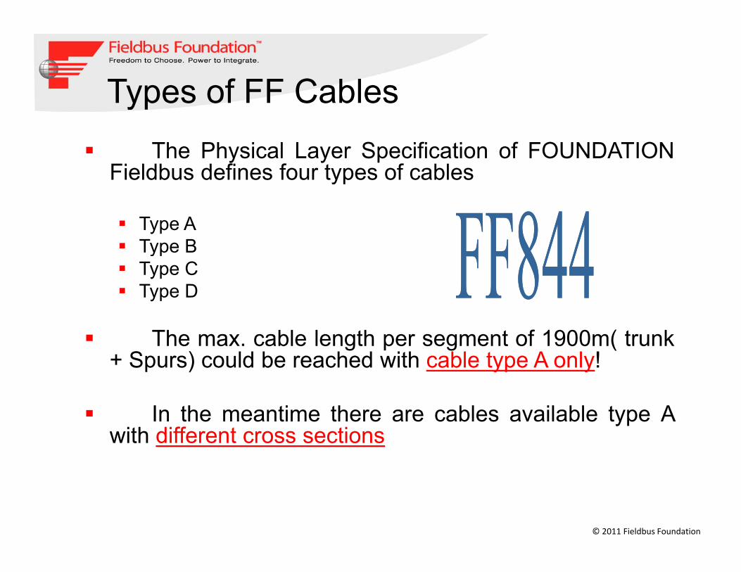
Types of FF CablesypThe Physical Layer Specification of FOUNDATION
Fieldbus defines four types of cablesFieldbus defines four types of cables
Type AType BType BType CType D
The max. cable length per segment of 1900m( trunk+ Spurs) could be reached with cable type A only!
In the meantime there are cables available type Awith different cross sections
© 2011 Fieldbus Foundation

Types of Cablesyp
© 2011 Fieldbus Foundation
a = not specified
FF Surge ProtectorsgSurge Protection ( 6.4 AG 181 V3.1)
Surge protection for FOUNDATION fieldbus devices may berequired in areas where induced voltage is an issue.
Thi i l d h l i i i it hThis includes areas such as close wiring proximity wherelarge inductive loads are started and stopped, or areas knownfor lightning incidence.
Surge suppression consists of a low-capacitance deviceinstalled at the device's electrical connection. It shall normallyappear as an open circuit to the spur and segment to preventpp p p g pany adverse effect on communications.
© 2011 Fieldbus Foundation

FF Surge Protectorsg
© 2011 Fieldbus Foundation

FF Surge Protectors - Summary
Surge suppression device should not measurably attenuate the fieldbus signal
g y
attenuate the fieldbus signal
Shall be installed at the Field Devices and host H1Shall be installed at the Field Devices and host H1 Interface
Current-limiting couplers ( Wiring Block spurs ) should not be used in combination with surge protectors. The surge protectors will cause failure ofprotectors. The surge protectors will cause failure of the current limiting circuits when a lightning strike occurs
© 2011 Fieldbus Foundation

FF Terminators
FOUNDATION fieldbus segments require EXACTLY two terminators,one at each end of the trunk (home run) cable. The terminator is( )comprised of an RC network that provides 100 Ω impedance.
The terminator allows the current-based FOUNDATION fieldbuscommunications signal to be viewed as a voltage while being offset ong g gthe DC segment voltage supply.
Most fieldbus power supplies and/or wiring blocks have a built-in segmentterminator. Some wiring components have switchable terminators.g pTerminators at a field device shall not be used (due to the impact on thewhole segment should the device need replacement)
© 2011 Fieldbus Foundation

FF Wiring Topologiesg p gSpur Topology (Bus with Spurs)
This topology consists of fieldbus devices connected to a multi-drop bus segment through a length ofThis topology consists of fieldbus devices connected to a multi drop bus segment through a length ofcable called a spur. This technology is technically acceptable, but generally not a good economicalchoice when there is a high density of devices.
Combination TopologyCombination TopologyCombinations of the above topologies must follow all the rules for maximum fieldbus network/segmentlength, and include the length of spurs in the total length calculation. These types of topologies arepreferred for designs using bricks with tray cable. Spurs are permitted to extend only from trunk linesand not from other spur lines.
© 2011 Fieldbus Foundation

FF Wiring Topologiesg p gDaisy Chain TopologyThis topology consists of a network/segment that is routed from device to device, andis connected at the terminals of the fieldbus device. It should not be used, as it isunacceptable, for maintenance purposes.
© 2011 Fieldbus Foundation

FF Wiring Topologies in Practice
© 2011 Fieldbus Foundation
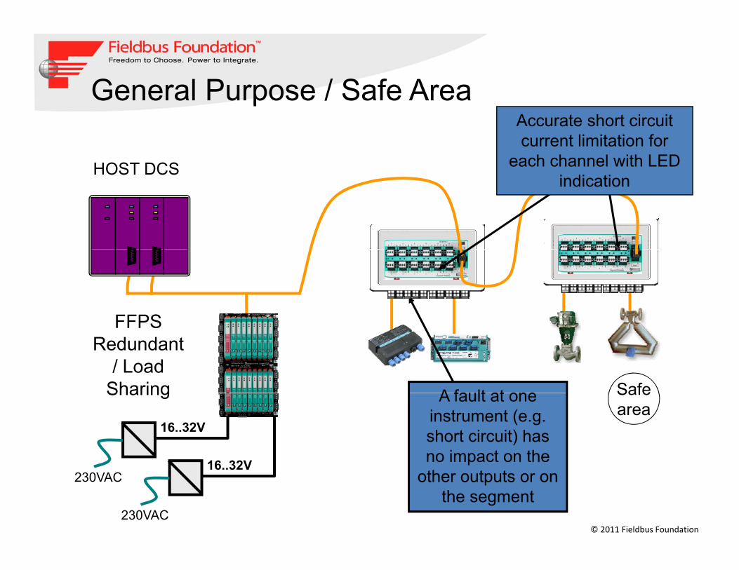
General Purpose / Safe AreapAccurate short circuit current limitation for
each channel with LED i di ti
HOST DCSindication
FFPS
SafeA fault at one
FFPS Redundant
/ Load Sharing Safe
areaA fault at one
instrument (e.g. short circuit) has no impact on the
16..32V
16 32V
Sharing
© 2011 Fieldbus Foundation
pother outputs or on
the segment230VAC
16..32V
230VAC

Fieldbus in Hazardous AreaRedundant FISCO
The first step
Simplifying validation
MAX power + FISCO
Re-inventing Intrinsic Safety
© 2011 Fieldbus Foundation
Re-inventing Intrinsic Safety

Zone 2 Topologyp gyZone2
Previous standardsPrevious standards
-Ex nA ( Non arcing) / Ex nL ( energy Limiting) / Exic Intrinsically Safe
-FNICO ( Non-Incendive)
Current standard – Exic
From 2007 onwards Ex nL and FNICO standards are omitted and replaced by Ex ic ( similar to IS)
© 2011 Fieldbus Foundation

Zone 2 Hazardous Area Concept Ex nL / Ex icpAccurate short circuit current limitation for
each channel with LEDHOST DCS each channel with LED indication
Ex nA
Ex nL / ic17 to 30V
A fault at one Zone2
17 to 30V, 500mA
A fault at one instrument (e.g. short circuit) has no impact on the
16..32V
16 32V
Zone2
© 2011 Fieldbus Foundation
pother outputs or on
the segment230VAC
16..32V
230VAC
AG181 REVISION 3.1 Official FF Design GuidelinesAG181 REVISION 3.1 Official FF Design Guidelines
© 2011 Fieldbus Foundation

Zone1 Topologyp gy
Non-IS(EEx d)Trunk and spurs must be installed in increased safety EEx e– Trunk and spurs must be installed in increased safety EEx e
IS ( FISCO, HPT, DART)
A full intrinsically safe fieldbus segment (FISCO)– Intrinsic safe trunk and spur– Requires the use of IS Power Repeaters/Power Link module– Requires the use of IS Power Repeaters/Power Link module
A mixture of EEx e and EEx I (High Power Trunk)– Trunk has to be installed in increased safetyy– Spurs are intrinsically safe– Allows the use of Non IS Power Supplies/Power Repeaters/Power
Links
© 2011 Fieldbus Foundation
High Power Intrinsically safe (DART)

Application Area - Zone 1 (EEx d)pp ( )
Segment Protector Ex meFieldbus Power HubPower Hub
Ex e
16..32V
16..32V230VAC InstrumentsEx d
© 2011 Fieldbus Foundation
Zone 1R-SP-E12 is resin filled as per Exd installation requirements

Application Area - Zone1 IS - HPTResin Filling for Zone 1 Installation
FieldBarrier
pp
Exd Trunk live disconnect switch
Installation
Zone 1
Fieldbus Power Hub
Ex e
Ex ia(FISCO + Entity)
Zone 0/116 32V
16..32V
230VAC
© 2011 Fieldbus Foundation
16..32V230VAC

Zone1 IS Enclosure solutions
FieldBarrierFieldbus
Zone 1
Power Hub
Ex e
Ex ia(FISCO + Entity)
Zone 0/116 32V
16..32V
230VAC
© 2011 Fieldbus Foundation
16..32V230VAC

DART Fieldbus
DART FieldbusThe Simplicity of Intrinsic SafetyDART FieldbusThe Simplicity of Intrinsic Safety
DART fieldbus provides:
The Simplicity of Intrinsic SafetyThe Simplicity of Intrinsic Safety
A completely intrinsically safe fieldbus segment in gas groups IIB and IIC with real power redundancy with load sharing and advanced diagnosticswith load sharing and advanced diagnostics
The Intrinsically Safe High-Power Trunk
© 2011 Fieldbus Foundation
The Intrinsically Safe High Power TrunkDART Fieldbus is certified according to the international I.S. standard IEC 60079-11
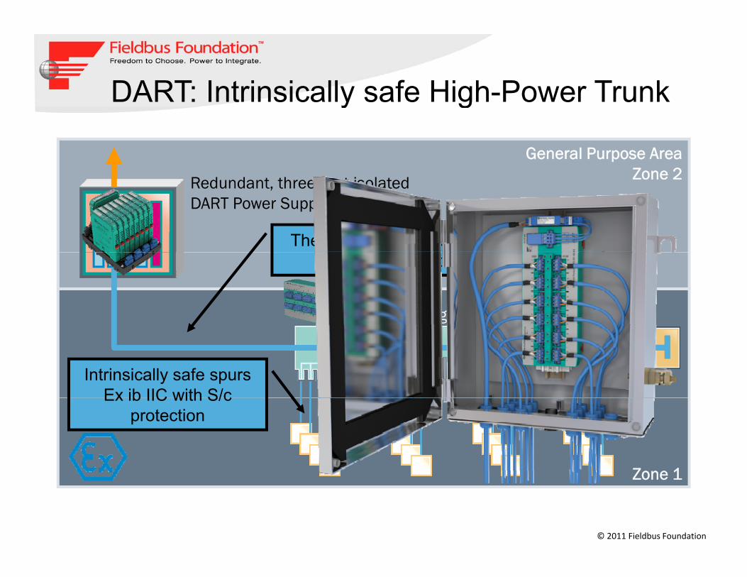
DART: Intrinsically safe High-Power Trunk
General Purpose AreaZone 2
y g
R d d t th t i l t dRedundant, three-port isolatedDART Power Supply
The intrinsically safe High-Power Trunk
DART Segment Protectors
protected by DART®
Intrinsically safe spursEx ib IIC with S/c
Z 1
Ex ib IIC with S/c protection
© 2011 Fieldbus Foundation
Zone 1

Evolution of Various FF Hazardous Area Topologies
Safe Area FISCO / FNICO FISCO Redundant HPT Field Barrier DARTSafe Area FISCO / FNICO FISCO Redundant HPT Field Barrier DART
Segment Current + + +Segment Voltage + + +Segment Voltage
Redundancy
Load Sharing FFPS
Physical Layer Diagnostics
Segment Design Mix
C bi t S + +Cabinet Space + +Initial Segment Cost (FFPS + Wiring Blocks) + + +Live Trunk Working
© 2011 Fieldbus Foundation
g
: Available : Not Available + : High : Low

FF Segment Designg g
H t d i F d ti Fi ldb t ?How to design Foundation Fieldbus segments?
© 2011 Fieldbus Foundation

Segment Design and Validation Tools
• Fieldbus allows to connect many devices on the same bus cable butsame bus cable, but…
How many devices can I really connect?• How many devices can I really connect?
• What cable should I use and what cable distances• What cable should I use, and what cable distances can I really achieve?
• What happens in case of a short circuit in the field?
© 2011 Fieldbus Foundation
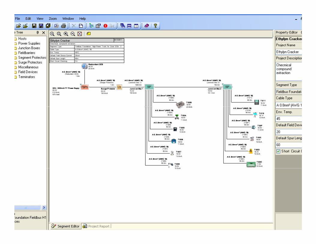
Segment Design and Validation Tools
• Graphical segment design tool example
• Download the NEW DesignMATE segment verification tool• Download the NEW DesignMATE segment verification tool
• www.segmentchecker.comwww.segmentchecker.com
• Various other tools are available with FF Vendors
© 2011 Fieldbus Foundation
© 2011 Fieldbus Foundation

© 2011 Fieldbus Foundation
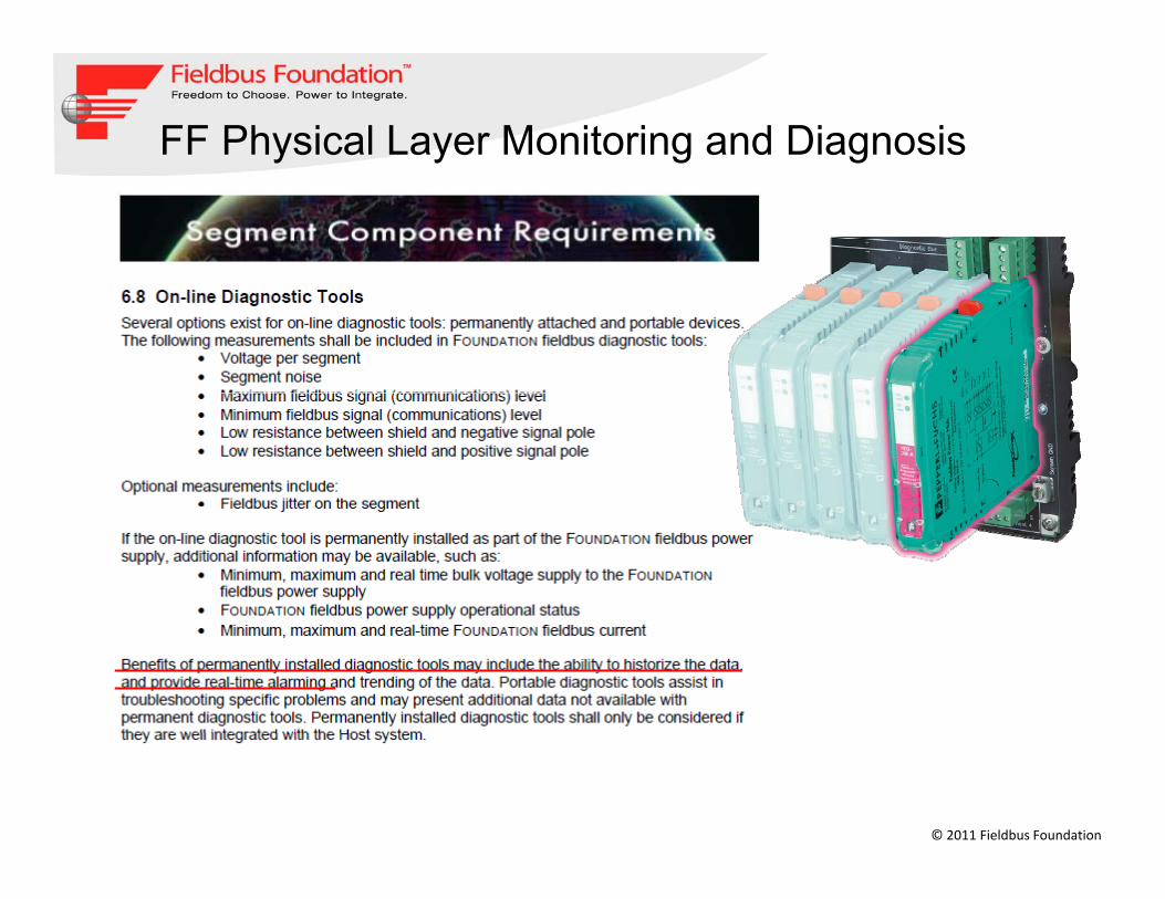
FF Physical Layer Monitoring and Diagnosis
© 2011 Fieldbus Foundation

Fieldbus Diagnostic Capabilities Have Evolved ARC ReportEvolved – ARC Report
© 2011 Fieldbus Foundation

Typical problems – and how to solve them
Tools to measure segment parameters
y
(voltage, current)Tools to measure segment health(termination, noise)Tool to display EMC problemsTools to test communicationTool to measure cable degradationTool to measure cable degradationover time (trending)Tool to visualize signal quality ofindividual devices (noise jitter telegram level)individual devices (noise, jitter, telegram level)Tool to allow remote access for expert
© 2011 Fieldbus Foundation

With Diagnostics of Physical Layer We Can….g y yCommission SegmentsMonitor Segments OnlinePredictive Fault finding of Segments
SEE what's going on in your physical layerKNOW h d h t t
SEE KNOW ACT
© 2011 Fieldbus Foundation
KNOW when and how to actACT in your Asset Management tool

Commissioning until nowgAlways on the critical pathManual step-by-step procedureManual, step by step procedureLabor intensiveRequires
Test Report
q– Screw driver– Check sheet– Pencil– Multimeter
O ill– OscilloscopeConnect one device at a timeDisconnect after testing
© 2011 Fieldbus Foundation
Disconnect after testing

Simple Commissioning Steps with ADM
Verify address settingWire up devices in the right locationWire up devices in the right locationCheck shieldingActivate communication Test
Report
Use automated work procedures– Testing – Documentation
All devices at onceWi i i di b d!
Commissioning Wizard
Wiring remains undisturbed!
© 2011 Fieldbus Foundation
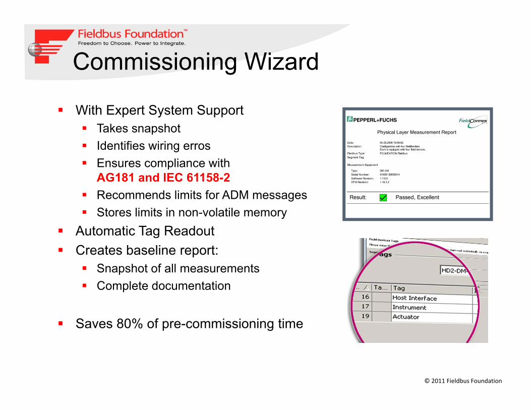
Commissioning Wizard
With Expert System SupportTakes snapshotTakes snapshotIdentifies wiring errosEnsures compliance with AG181 and IEC 61158-2AG181 and IEC 61158-2Recommends limits for ADM messagesStores limits in non-volatile memory
Automatic Tag ReadoutAutomatic Tag ReadoutCreates baseline report:
Snapshot of all measurements C l t d t tiComplete documentation
Saves 80% of pre-commissioning time
© 2011 Fieldbus Foundation
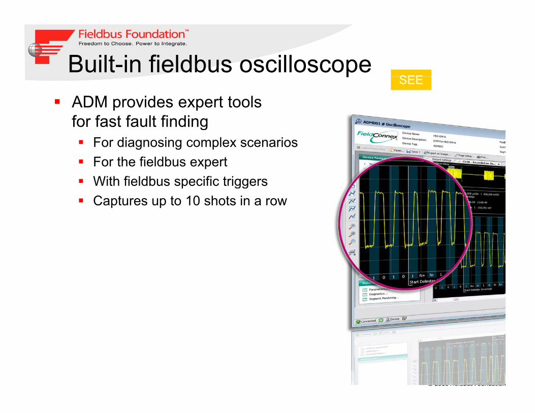
Built-in fieldbus oscilloscopeSEE
pADM provides expert tools for fast fault finding
SEE
gFor diagnosing complex scenariosFor the fieldbus expertWith fieldbus specific triggersWith fieldbus specific triggersCaptures up to 10 shots in a row
© 2011 Fieldbus Foundation

Online monitoring KNOWgThe Advanced Diagnostic Module:
Monitors physical layer health
KNOW
p y yDetects changing conditionsSends messages with time stamps
Expert System diagnoses faults:Precisely diagnoses causes y gCreates messages with clear textEnables proactive plant up keep Alerts before the segment failsAlerts before the segment fails
© 2011 Fieldbus Foundation

Online monitoringKNOW
gClean layout shows boundaries
Displays measurement values
KNOW
p yHighlights violations with color coding: Issues diagnostic messages
Good value
Maintenance required
© 2011 Fieldbus Foundation
Out of specification

Diagnostic Menu ACTgExpert System delivers clear text information for fast fault
ACT
finding1 Active messages2 Actionable information with
11
332 Actionable information with solution guideance based on expert system
3 History with timestamps
33
3 History with timestampsWhen the failure…
… occureddisappeared
222
… disappearedExport function for external analysis and storage
© 2011 Fieldbus Foundation

The effect of Advanced Diagnostics
Plan and purchase
Install and commission Operate and maintain ACT
TroubleshootMonitorCommission
Longer plant uptimeash
Flow
KNOW
g p p Know before you act Actionable information in clear text
Ca
SEE
Verify against original design Automated checkout procedures
© 2011 Fieldbus Foundation
Segment Checker: design of the physical layer

ConclusionFollow proper selection of components, design andinstallation guidelinesinstallation guidelines
System design guideline in AG 181 V3 1 will assist youSystem design guideline in AG 181 V3.1 will assist youto select right components for your NetworkSegment Design tools based on AG 181 V3.1 and IEC61158-2 assist you to design your segmentsAlways use Approved and registered productsRight diagnostic tools helps to reduce installation andRight diagnostic tools helps to reduce installation andcommissioning time
© 2011 Fieldbus Foundation

Thank You
Fieldbus FoundationIndia Committee
21st September, 2011
© 2011 Fieldbus Foundation
FFIC : Automation 2011 ‐Mumbai
www.fieldbus.org