Embed Size (px)
Citation preview
8113755
CMMT-ST-C8-1C-...-S0Servo drive
81137552019-10a[8113757]
Description |Assembly, Installation

Translation of the original instructions
AKULON®, BISS®, CiA®, EtherCAT®, EtherNet/IP®, PI PROFIBUS PROFINET®, PHOENIX CONTACT® areregistered trademarks of the respective trademark owners in certain countries.
2 Festo — CMMT-ST-C8-1C-...-S0 — 2019-10a

3Festo — CMMT-ST-C8-1C-...-S0 — 2019-10a
1 About this document................................................................................................... 5
1.1 Target group................................................................................................................. 5
1.2 Applicable documents.................................................................................................. 5
1.3 Product variants........................................................................................................... 5
1.4 Product labelling.......................................................................................................... 6
1.5 Specified standards...................................................................................................... 7
2 Safety........................................................................................................................... 8
2.1 Safety Instructions....................................................................................................... 8
2.2 Intended Use................................................................................................................ 8
2.2.1 Range of application............................................................................................... 9
2.2.2 Permissible components.........................................................................................9
2.3 Training of qualified personnel..................................................................................... 9
2.4 CE marking................................................................................................................... 9
2.5 Safety engineering approval......................................................................................... 9
2.6 UL/CSA certification..................................................................................................... 10
3 Additional information................................................................................................ 10
4 Service..........................................................................................................................10
5 Product overview......................................................................................................... 10
5.1 Scope of delivery.......................................................................................................... 10
5.2 System structure.......................................................................................................... 10
5.2.1 Product design........................................................................................................11
5.2.2 Overview of connection technology........................................................................ 15
6 Transport and storage................................................................................................. 16
7 Assembly..................................................................................................................... 17
7.1 Mounting clearances.................................................................................................... 17
7.2 Installation................................................................................................................... 19
8 Installation.................................................................................................................. 21
8.1 Safety............................................................................................................................ 21
8.2 EMC-compliant installation........................................................................................... 21
8.3 Connection example..................................................................................................... 23
8.4 Interfaces..................................................................................................................... 24
8.4.1 [X1A], inputs and outputs for the higher-order PLC................................................. 24
8.4.2 [X1C], reference switch/limit switch........................................................................ 28
8.4.3 [X2], encoder interface............................................................................................ 29
8.4.4 [X18], standard Ethernet......................................................................................... 31
8.4.5 [XF1 IN] and [XF2 OUT], real-time Ethernet (RTE) port 1 and 2................................. 32
8.5 Motor connection......................................................................................................... 34
8.6 Load and logic power supply........................................................................................ 36
8.7 Cross-wiring of several servo drives............................................................................. 37
9 Malfunctions............................................................................................................... 38
Table of contents

9.1 Diagnostics via LEDs......................................................................................................38
9.1.1 Device status displays........................................................................................... 39
9.1.2 Interface status [X18]............................................................................................. 42
9.1.3 Device and interface status, EtherCAT................................................................... 43
9.1.4 Device and interface status, ProfiNet..................................................................... 44
9.1.5 Device and interface status, EtherNet/IP............................................................... 45
10 Disassembly................................................................................................................. 47
11 Technical data.............................................................................................................. 48
11.1 Technical data, general..................................................................................................48
11.2 Technical data, electrical............................................................................................... 51
11.2.1 Load and logic power supply [X9]........................................................................... 51
11.2.2 Power specifications, motor connection [X6].......................................................... 52
11.2.3 Encoder interfaces [X2].......................................................................................... 52
11.2.4 Digital inputs and outputs [X1A]............................................................................ 53
11.2.5 Reference switch [X1C]........................................................................................... 57
11.2.6 Standard Ethernet [X18], parameterisation interface.............................................. 58
11.2.7 Real-time Ethernet [XF1 IN], [XF2 OUT]................................................................... 58
11.3 Characteristic curves..................................................................................................... 59
11.4 Technical data UL/CSA certification...............................................................................59
4 Festo — CMMT-ST-C8-1C-...-S0 — 2019-10a
5Festo — CMMT-ST-C8-1C-...-S0 — 2019-10a
1 About this document
1.1 Target groupThe document is targeted towards individuals who perform assembly, installation and service work onthe product.
1.2 Applicable documents
All available documents for the product è www.festo.com/pk.
The user documentation for the product also includes the following documents:
Designation Contents
Product instruction manual Installation, safety sub-function
Detailed description of assembly, installationProduct descriptions
Detailed description of safety sub-function
Description/online help plug-in Plug-in:– Functions and operation of the software– Initial commissioning assistantFirmware functions:– Configuration and parameterisation– Operating modes and operational functions– Diagnostics and optimisationBus protocol/control:– Device profile– Controller and parameterisation
Festo Automation Suite onlinehelp
– Function of the Festo Automation Suite– Management and integration of device-specific plug-ins
Tab. 1 User documentation for the product
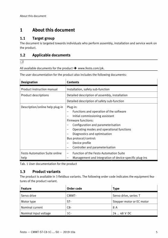
1.3 Product variantsThe product is available in 3 fieldbus variants. The following order code indicates the equipment fea-tures of the product variant.
Feature Order code Type
Servo drive CMMT- Servo drive, series T
Motor type ST- Stepper motor or EC motor
Nominal current C8- 8 A
Nominal input voltage 1C- 24 … 48 V DC
About this document
Feature Order code Type
EC- EtherCAT
EP- EtherNet/IP
Bus protocol/activation
PN- PROFINET
Safety function S0 Basic safety
Tab. 2 Product variants CMMT-ST-... (e.g. CMMT-ST-C8-1C-EC-S0)
This documentation refers to the following version:– Servo drive CMMT-ST-...-S0, revision 1 and higher, see product labelling.This is the first available revision.• For later revisions of the product, check whether updated documentation is availableè www.festo.com/pk.
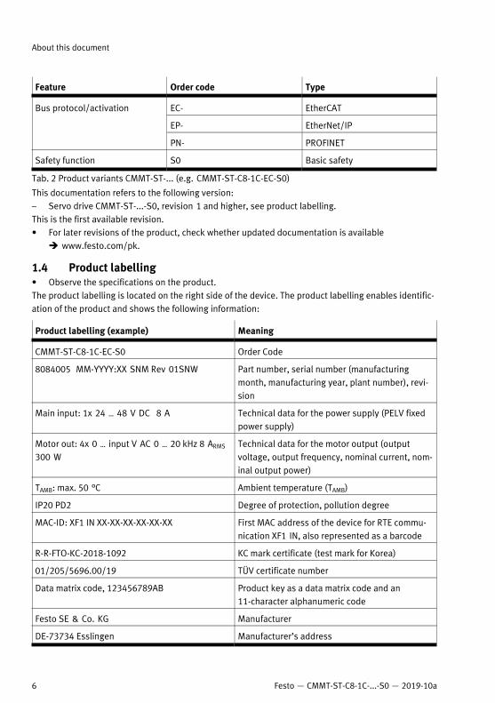
1.4 Product labelling• Observe the specifications on the product.The product labelling is located on the right side of the device. The product labelling enables identific-ation of the product and shows the following information:
Product labelling (example) Meaning
CMMT-ST-C8-1C-EC-S0 Order Code
8084005 MM-YYYY:XX SNM Rev 01SNW Part number, serial number (manufacturingmonth, manufacturing year, plant number), revi-sion
Main input: 1x 24 … 48 V DC 8 A Technical data for the power supply (PELV fixedpower supply)
Motor out: 4x 0 … input V AC 0 … 20 kHz 8 ARMS
300 WTechnical data for the motor output (outputvoltage, output frequency, nominal current, nom-inal output power)
TAMB: max. 50 °C Ambient temperature (TAMB)
IP20 PD2 Degree of protection, pollution degree
MAC-ID: XF1 IN XX-XX-XX-XX-XX-XX First MAC address of the device for RTE commu-nication XF1 IN, also represented as a barcode
R-R-FTO-KC-2018-1092 KC mark certificate (test mark for Korea)
01/205/5696.00/19 TÜV certificate number
Data matrix code, 123456789AB Product key as a data matrix code and an11-character alphanumeric code
Festo SE & Co. KG Manufacturer
DE-73734 Esslingen Manufacturer’s address
About this document
6 Festo — CMMT-ST-C8-1C-...-S0 — 2019-10a

Product labelling (example) Meaning
Made in Germany Manufactured in Germany
Tab. 3 Product labelling (example)
Warning symbol on the front of the productThe following warning symbol can be seen on the front of the product:
1 Attention! Hot surface
Fig. 1 Warning symbol on the front of the product (example CMMT-ST-…EC)
General meaning Meaning for the CMMT-ST
Attention! Hot surface Metallic housing parts of the device can reach high temperaturesduring operation.
Tab. 4 Meaning of the warning symbol
1.5 Specified standards
Version
EN 60204-1:2018-09 EN 61800-3:2004+A1:2012
EN 61131-2:2007 EN 61800-5-2:2017
Tab. 5 Standards specified in the document
About this document
7Festo — CMMT-ST-C8-1C-...-S0 — 2019-10a

2 Safety
2.1 Safety InstructionsGeneral safety instructions – Assembly and installation should only be carried out by qualified personnel.– Only use the product if it is in perfect technical condition.– Only use the product in original status without unauthorised modifications.– Do not carry out repairs on the product. If defective, replace the product immediately.– Observe labelling on the product.– This product can generate high frequency malfunctions, which may make it necessary to imple-
ment interference suppression measures in residential areas.– Take into consideration the ambient conditions at the location of use.
The safety function might fail and malfunctions might occur if you do not comply with the para-meters required for the ambient and connection conditions.
– Never remove or insert a plug when the power is switched on.– Install the product in a suitable control cabinet. The minimum degree of protection required for
the control cabinet is IP54.– Prior to commissioning, ensure that the resulting movements of the connected actuator techno-
logy cannot endanger anyone.– During commissioning: systematically check all control functions and the communication and sig-
nal interface between controller and servo drive.– Keep the documentation somewhere safe throughout the entire product lifecycle.In the event of damage caused by unauthorised manipulation or any form of use other than that inten-ded, the warranty is invalidated and the manufacturer is not liable for damages.In the event of damage caused by using unauthorised software or firmware with the device, the war-ranty is invalidated, and the manufacturer is not liable for damages.
Safety instructions for the safety sub-functions of the product è Description Safety sub-function.
2.2 Intended UseThe servo drive CMMT-ST is intended to supply a stepper motor or an EC motor with power, as well asto regulate them. The integrated electronics permit regulation of torque (current), rotational speedand position. Use exclusively:– In perfect technical condition– In its original condition, without unauthorised modifications– Within the limits of the product defined by the technical data è 11 Technical data– In an industrial environment
Intended use of the safety sub-functions for the product è Description Safety sub-function.
Safety
8 Festo — CMMT-ST-C8-1C-...-S0 — 2019-10a

2.2.1 Range of applicationThe device is intended for use in an industrial environment.The device is intended to be installed in a control cabinet. The minimum degree of protection requiredfor the control cabinet is IP54.
2.2.2 Permissible components
Supported motors:– Stepper motors– EC motorsThe servo drive supports motors with or without an integrated holding brake (electrical spring-oper-ated brake). The holding brake is actuated automatically by the controller enable of the servo drive.The actuation concept is based on the assumption that a drive that is already stationary is being held.The actuation system is not designed for decelerating a moving drive. If a moving drive is decelerated,this can cause excessive wear on the brake.
Motor configuration Behaviour following removal of controller enable
Motor without holding brake The drive can move freely.
Motor with holding brake The holding brake is applied and holds the motor and axis in posi-tion.
Tab. 6 Example: removal of controller enable
The holding brake must be designed for the load torque to be stopped. Detailed information aboutbrake control è Online help for the CMMT-ST plug-in.
Supported encoders:– BiSS-C encoders– Incremental encodersAdditional information è www.festo.com/catalogue.
2.3 Training of qualified personnelThe product may be installed and commissioned only by a qualified electrical engineer who is familiarwith:– The installation, operation and maintenance of electrical control systems– The applicable regulations for operating safety-related systemsWork on safety-related systems may only be carried out by qualified personnel trained in safety engin-eering.
2.4 CE markingThe product has the CE marking.The product-related EU directives and standards are listed in the declaration of conformityè www.festo.com/sp.
2.5 Safety engineering approvalThe product is a safety device in accordance with the Machinery Directive. For details of the safety-ori-ented standards and test values that the product complies with and fulfils, see è Description Safety
Safety
9Festo — CMMT-ST-C8-1C-...-S0 — 2019-10a

sub-function, Technical data, safety engineering. Please note that compliance with the named stand-ards is limited to the CMMT-ST-...-S0.
2.6 UL/CSA certificationTechnical data and environmental conditions may be subject to change in order to comply with Under-writers Laboratories Inc. (UL) certification requirements for the USA and Canada.Deviating values è 11.4 Technical data UL/CSA certification.
3 Additional information– Accessories è www.festo.com/catalogue.– Spare parts è www.festo.com/spareparts.– All available documents for the product and current versions of the firmware and commissioning
software è www.festo.com/sp.
4 ServiceContact your regional Festo contact person if you have technical questions è www.festo.com.
5 Product overview
5.1 Scope of delivery
Component Number
Servo drive CMMT-ST-... 1
Assortment of plugs NEKM-C-22 1
H-rail clamp (premounted) 1
Instruction manual CMMT-ST-... 1
Tab. 7 Scope of delivery
Below are some examples of the available accessories:– Patch cable for linkage of the RTE interface
Up-to-date information on the accessories è www.festo.com/catalogue.
5.2 System structureThe servo drive CMMT-ST is a 1-axis servo drive for controlling a stepper motor or an EC motor withconnected mechanisms, e.g. an axis from Festo. The device is controlled by a higher-level controllerusing the bus protocol EtherCAT, EtherNet/IP or PROFINET, depending on the product version, via areal time Ethernet interface.The device can be parameterised via a PC using either the real-time Ethernet interface or the separatestandard Ethernet interface.
Additional information
10 Festo — CMMT-ST-C8-1C-...-S0 — 2019-10a

The device is an extra-low-voltage controller. The load and logic power supply must be provided by aPELV fixed power supply.
1 Servo drive CMMT-ST
2 Stepper motor or EC motor with drive
3 Fixed power supply (or supplies) for logicand load voltage (PELV)
4 PC with Ethernet connection for paramet-erisation
5 Bus/network
Fig. 2 System structure (example)
5.2.1 Product designThe device has a compact design. The connections are on the front, top and bottom of the device aspin header, socket strip or RJ45 bushing.The ventilation slots on the bottom, top and left side of the device ensure sufficient air flow for coolingthe device. The metal housing parts forms the cooling elements. Heat is also dissipated to the surroundings viathe cooling elements. The device does not have a fan.
Product overview
11Festo — CMMT-ST-C8-1C-...-S0 — 2019-10a
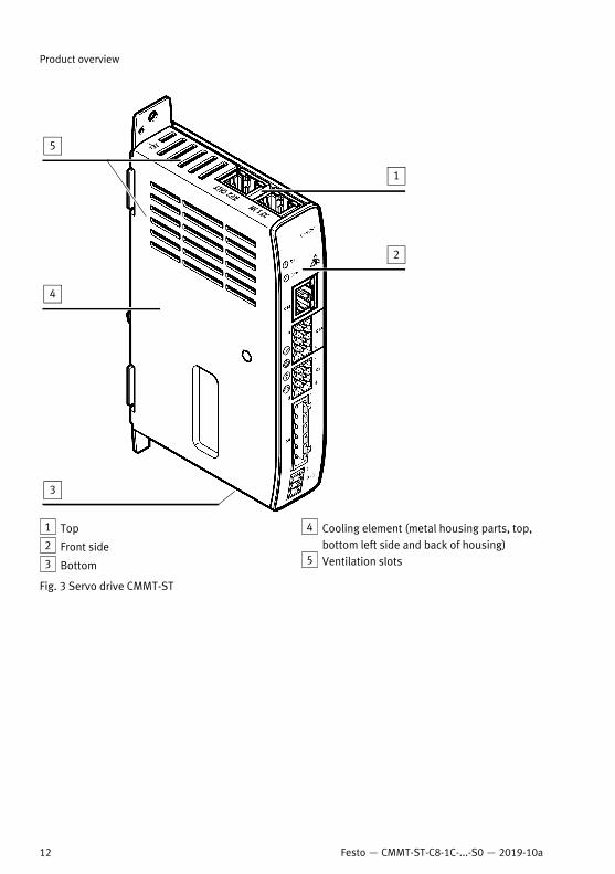
1 Top
2 Front side
3 Bottom
4 Cooling element (metal housing parts, top,bottom left side and back of housing)
5 Ventilation slots
Fig. 3 Servo drive CMMT-ST
Product overview
12 Festo — CMMT-ST-C8-1C-...-S0 — 2019-10a

1 top hole for wall mounting
2 Retaining screw for t-rail clamp
3 T-rail clamp
4 Bottom slot for wall mounting
5 Hood (right side of housing)
Fig. 4 Elements on the back
There is a hole at the top and a slot for wall mounting at the bottom of the back. The t-rail clamp ismounted in the centre of the back.
Product overview
13Festo — CMMT-ST-C8-1C-...-S0 — 2019-10a

1 Ventilation slots 2 Bottom of the CMMT-ST
Fig. 5 Bottom
Product overview
14 Festo — CMMT-ST-C8-1C-...-S0 — 2019-10a
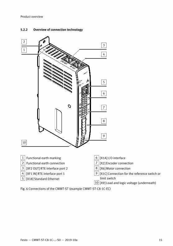
5.2.2 Overview of connection technology
1 Functional earth marking
2 Functional earth connection
3 [XF2 OUT] RTE interface port 2
4 [XF1 IN] RTE interface port 1
5 [X18] Standard Ethernet
6 [X1A] I/O interface
7 [X2] Encoder connection
8 [X6] Motor connection
9 [X1C] Connection for the reference switch orlimit switch
10 [X9] Load and logic voltage (underneath)
Fig. 6 Connections of the CMMT-ST (example CMMT-ST-C8-1C-EC)
Product overview
15Festo — CMMT-ST-C8-1C-...-S0 — 2019-10a

6 Transport and storage– Protect the product during transport and storage from excessive stress factors. Excessive stress
factors include: – Mechanical stresses– Impermissible temperatures– Moisture– Aggressive atmospheres
– Store and transport the product in its original packaging or installed in the control cabinet. Theoriginal packaging offers sufficient protection from typical stresses.
Transport and storage
16 Festo — CMMT-ST-C8-1C-...-S0 — 2019-10a

7 AssemblyDimensions
Fig. 7 Dimensions [mm]
7.1 Mounting clearancesThe servo drives of the series CMMT-ST can be arrayed next to each other.For effective output currents > 4.5 A, mounting clearances may be required on both sides so that theheat generated during operation can be removed by allowing sufficient air to flow.Detailed information about the required mounting clearances and any derating that may be necessaryas a function of the ambient temperature è Fig.15
Assembly
17Festo — CMMT-ST-C8-1C-...-S0 — 2019-10a
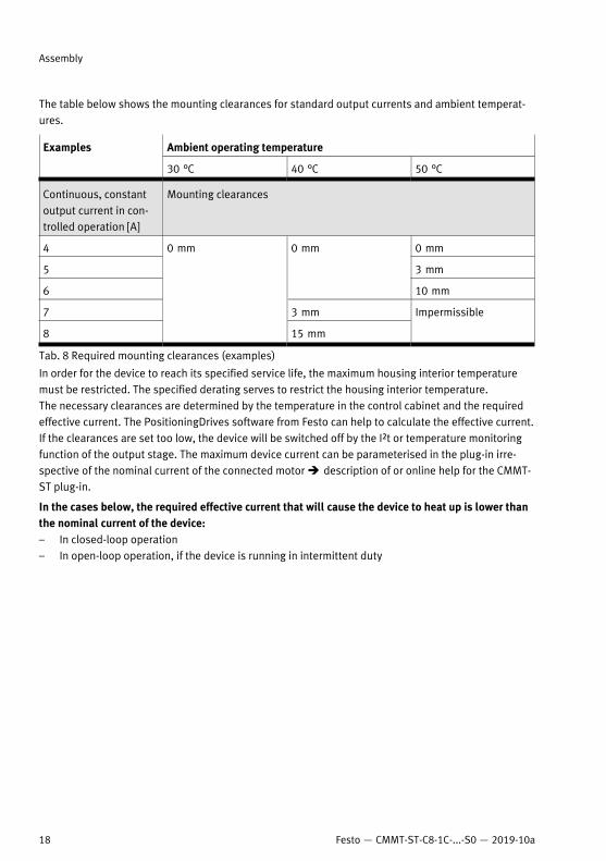
The table below shows the mounting clearances for standard output currents and ambient temperat-ures.
Ambient operating temperatureExamples
30 °C 40 °C 50 °C
Continuous, constantoutput current in con-trolled operation [A]
Mounting clearances
4 0 mm
5 3 mm
6
0 mm
10 mm
7 3 mm
8
0 mm
15 mm
Impermissible
Tab. 8 Required mounting clearances (examples)
In order for the device to reach its specified service life, the maximum housing interior temperaturemust be restricted. The specified derating serves to restrict the housing interior temperature.The necessary clearances are determined by the temperature in the control cabinet and the requiredeffective current. The PositioningDrives software from Festo can help to calculate the effective current. If the clearances are set too low, the device will be switched off by the I²t or temperature monitoringfunction of the output stage. The maximum device current can be parameterised in the plug-in irre-spective of the nominal current of the connected motor è description of or online help for the CMMT-ST plug-in.
In the cases below, the required effective current that will cause the device to heat up is lower thanthe nominal current of the device:– In closed-loop operation– In open-loop operation, if the device is running in intermittent duty
Assembly
18 Festo — CMMT-ST-C8-1C-...-S0 — 2019-10a
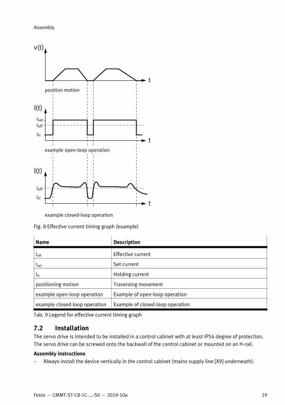
Fig. 8 Effective current timing graph (example)
Name Description
Ieff Effective current
Iset Set current
IH Holding current
positioning motion Traversing movement
example open-loop operation Example of open-loop operation
example closed-loop operation Example of closed-loop operation
Tab. 9 Legend for effective current timing graph
7.2 InstallationThe servo drive is intended to be installed in a control cabinet with at least IP54 degree of protection.The servo drive can be screwed onto the backwall of the control cabinet or mounted on an H-rail.
Assembly instructions– Always install the device vertically in the control cabinet (mains supply line [X9] underneath).
Assembly
19Festo — CMMT-ST-C8-1C-...-S0 — 2019-10a
– Maintain minimum distances and mounting clearance to guarantee sufficient air flow. The ambientair in the control cabinet must be able to flow through the device from bottom to top withouthindrance. Detailed information about the required mounting clearances and any power reductionthat may be necessary as a function of the ambient temperature è Fig.15.
– Take into account the required clearance for the wiring (connecting cables of the device must berouted from above, from below and from the front).
– Do not mount any temperature-sensitive components near the device. The device can becomevery hot during operation (switch-off temperature of the temperature monitoringfunction è Technical data).
– When mounting on an H-rail: use a DIN mounting rail TH 35-7.5 or TH 35-15 in accordance withEN 60715.
– When mounting on the backwall of the control cabinet: screw the device on vertically and flat tothe mounting surface.
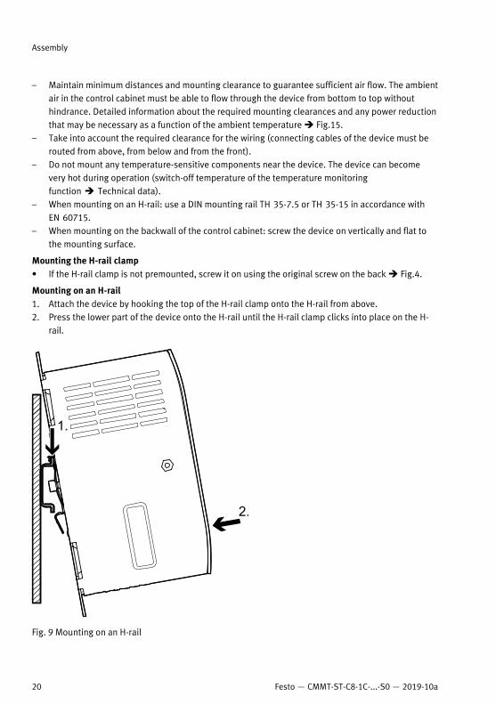
Mounting the H-rail clamp• If the H-rail clamp is not premounted, screw it on using the original screw on the back è Fig.4.
Mounting on an H-rail1. Attach the device by hooking the top of the H-rail clamp onto the H-rail from above.2. Press the lower part of the device onto the H-rail until the H-rail clamp clicks into place on the H-
rail.
Fig. 9 Mounting on an H-rail
Assembly
20 Festo — CMMT-ST-C8-1C-...-S0 — 2019-10a
Wall mountingThe backwall of the device has a hole at the top and a cutout at the bottom. The device is screwed ver-tically and flat to the mounting surface using the hole and the cutout.1. If an H-rail clamp is mounted on the back, remove it.2. Mount the servo drive on the backwall of the control cabinet with suitable screws while complying
with the assembly instructions.
8 Installation
8.1 SafetyWARNING!
Danger of burns from hot housing surfaces.Metallic housing parts can reach high temperatures during operation.Contact with metal housing parts can cause burn injuries.• Do not touch metallic housing parts.• After the power supply is switched off, let the device cool down to room temperature.
8.2 EMC-compliant installation
A non-EMC-compliant installation can lead to signal interference on the encoder, motor or communica-tion cables.
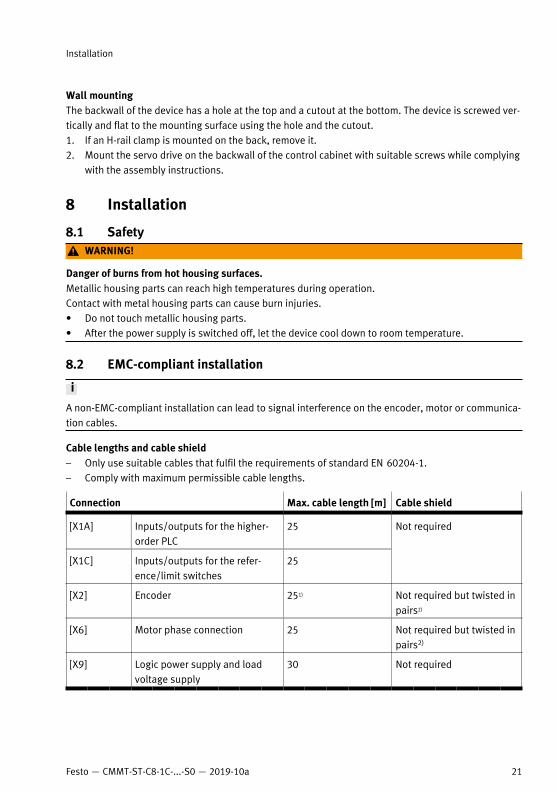
Cable lengths and cable shield– Only use suitable cables that fulfil the requirements of standard EN 60204-1.– Comply with maximum permissible cable lengths.
Connection Max. cable length [m] Cable shield
[X1A] Inputs/outputs for the higher-order PLC
25
[X1C] Inputs/outputs for the refer-ence/limit switches
25
Not required
[X2] Encoder 251) Not required but twisted inpairs2)
[X6] Motor phase connection 25 Not required but twisted inpairs2)
[X9] Logic power supply and loadvoltage supply
30 Not required
Installation
21Festo — CMMT-ST-C8-1C-...-S0 — 2019-10a
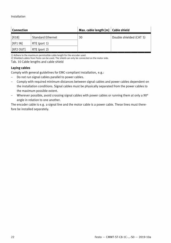
Connection Max. cable length [m] Cable shield
[X18] Standard Ethernet
[XF1 IN] RTE (port 1)
[XF2 OUT] RTE (port 2)
30 Double shielded (CAT 5)
1) Adhere to the maximum permissible cable length for the encoder used.2) Shielded cables from Festo can be used. The shield can only be connected on the motor side.
Tab. 10 Cable lengths and cable shield
Laying cablesComply with general guidelines for EMC-compliant installation, e.g.:– Do not run signal cables parallel to power cables.– Comply with required minimum distances between signal cables and power cables dependent on
the installation conditions. Signal cables must be physically separated from the power cables tothe maximum possible extent.
– Wherever possible, avoid crossing signal cables with power cables or running them at only a 90°angle in relation to one another.
The encoder cable is e.g. a signal line and the motor cable is a power cable. These lines must there-fore be installed separately.
Installation
22 Festo — CMMT-ST-C8-1C-...-S0 — 2019-10a

8.3 Connection example
1 BiSS-C or incremental encoder
2 EC motor or stepper motor
3 PELV fixed power supply for logic voltage(24 V)
4 PELV fixed power supply for load voltage(24 V … 48 V)
Fig. 10 Connection example
Installation
23Festo — CMMT-ST-C8-1C-...-S0 — 2019-10a

8.4 Interfaces
8.4.1 [X1A], inputs and outputs for the higher-order PLCThe I/O interface [X1A] is located on the front of the device. This interface features:– 2 freely configurable digital outputs (parameterisable switching logic, PNP logic or NPN logic)– 2 freely configurable digital inputs (parameterisable switching logic, PNP logic or NPN logic)– 1 digital input for the power stage enable and reset error functions; whether or not the function
will be used can be parameterised in the plug-in (parameterisable switching logic, PNP logic orNPN logic)
– 2 inputs for the circuitry of the safety sub-function STO (#STO-A, #STO-B)– 2 contacts for the circuitry of the diagnostic contact of the safety sub-function STO (STA-C1,
STA-C2)Detailed information on the circuitry of the product safety sub-functions can be found in the Descrip-tion Safety sub-function è 1.2 Applicable documents.The functional inputs and outputs of this I/O interface are used for coupling to a higher-order PLC,for example. The devices connected to the CMMT-ST all need to have the same switching logic(PNP/NPN). The configuration
PNP and NPN logic– PNP logic means that a potential is switched.– NPN logic means that earth is switched.The required switching logic can be parameterised using the CMMT-ST plug-in è description of oronline help for the CMMT-ST plug-in.
Signal Level Input Output
Logic 0 0 V Internal via pull-down resistor Internal via pull-down resistor
Logic 1 24 V – Via high-side driver (delivers cur-rent)
Tab. 11 PNP logic
Signal Level Input Output
Logic 0 24 V Internal via pull-up resistor Internal via pull-up resistor
Logic 1 0 V – Via low-side driver (consumes cur-rent)
Tab. 12 NPN logic
Installation
24 Festo — CMMT-ST-C8-1C-...-S0 — 2019-10a
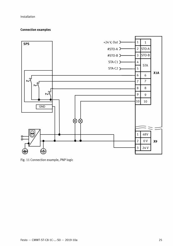
Connection examples
Fig. 11 Connection example, PNP logic
Installation
25Festo — CMMT-ST-C8-1C-...-S0 — 2019-10a

Fig. 12 Connection example, NPN logic
Installation
26 Festo — CMMT-ST-C8-1C-...-S0 — 2019-10a
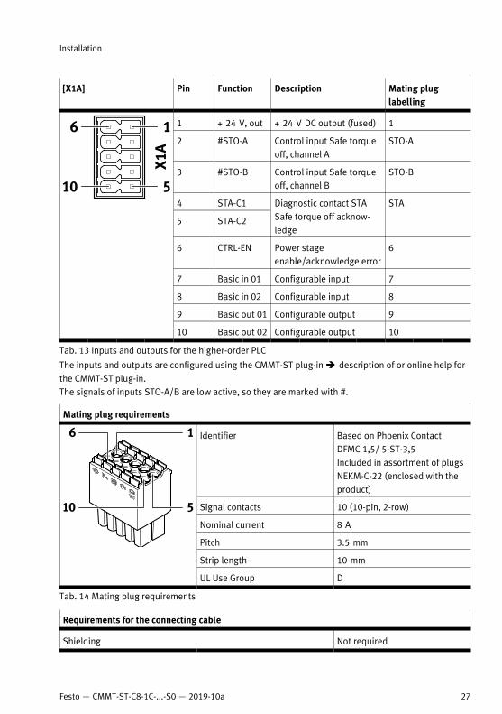
[X1A] Pin Function Description Mating pluglabelling
1 + 24 V, out + 24 V DC output (fused) 1
2 #STO-A Control input Safe torqueoff, channel A
STO-A
3 #STO-B Control input Safe torqueoff, channel B
STO-B
4 STA-C1
5 STA-C2
Diagnostic contact STASafe torque off acknow-ledge
STA
6 CTRL-EN Power stageenable/acknowledge error
6
7 Basic in 01 Configurable input 7
8 Basic in 02 Configurable input 8
9 Basic out 01 Configurable output 9
10 Basic out 02 Configurable output 10
Tab. 13 Inputs and outputs for the higher-order PLC
The inputs and outputs are configured using the CMMT-ST plug-in è description of or online help forthe CMMT-ST plug-in. The signals of inputs STO-A/B are low active, so they are marked with #.
Mating plug requirements
Identifier Based on Phoenix ContactDFMC 1,5/ 5-ST-3,5Included in assortment of plugsNEKM-C-22 (enclosed with theproduct)
Signal contacts 10 (10-pin, 2-row)
Nominal current 8 A
Pitch 3.5 mm
Strip length 10 mm
UL Use Group D
Tab. 14 Mating plug requirements
Requirements for the connecting cable
Shielding Not required
Installation
27Festo — CMMT-ST-C8-1C-...-S0 — 2019-10a

Requirements for the connecting cable
Min. conductor cross section incl. plastic wire end sleeve1) 0.2 mm2
Max. conductor cross section incl. plastic wire end sleeve 1.5 mm2
Max. length 25 m
1) The conductor cross section used must be suitable for the currents that arise. If flexible flying leads are used with plastic wire endsleeves, minimum cross sections of 0.14 mm² are possible.
Tab. 15 Requirements for the connecting cable
8.4.2 [X1C], reference switch/limit switchThe connection [X1C] is located on the front of the device and is used to connect the reference switchor a limit switch. The switching logic of the input can be parameterised (PNP logic or NPN logic).
[X1C] Pin Function Description Mating pluglabelling
1 +24 V, out + 24 V DC output (fused) +
2 REF/IN Reference signal/limitswitch signal
IN
3 0 V/GND Reference potential, refer-ence switch
-
Tab. 16 Connection for the reference switch/limit switch
Mating plug requirements
Designation Based on Phoenix ContactFK-MCP 1,5/ 3-ST-3,5Included in assortment of plugsNEKM-C-22 (enclosed with theproduct)
Signal contacts 3
Nominal current 8 A
Grid dimension 3.5 mm
Strip length 9 mm
UL Use Group D
Tab. 17 Mating plug requirements
Cable requirements
Shielding Not required
Min. conductor cross section incl. plastic cable end sleeve1) 0.14 mm2
Max. conductor cross section incl. plastic cable end sleeve 1.5 mm2
Installation
28 Festo — CMMT-ST-C8-1C-...-S0 — 2019-10a

Cable requirements
Max. length 25 m
1) The conductor cross section used must be suitable for the currents that arise.
Tab. 18 Cable requirements
8.4.3 [X2], encoder interfaceThe encoder interface [X2] is located on the front of the device. Communication with the encoder isperformed via this interface. The encoder signals are received, and the encoder is supplied withvoltage.
The following encoders are supported:– Incremental encoders with AB signals (quadrature encoder)– Absolute encoders with BiSS C protocol
[X2] Pin Function Description Mating pluglabelling
1 A_IN A signal input 1
2 B_IN B signal input 2
3 IDX_IN Index signal input 3
4 +5 V 5 V encoder supply 4
5 #A_IN A signal input, inverse 5
6 #B_IN B signal input, inverse 6
7 #IDX_IN Index signal input, inverse 7
8 GND Reference potential ofencoder supply
8
Tab. 19 Incremental encoders with AB signals (quadrature encoder)
Installation
29Festo — CMMT-ST-C8-1C-...-S0 — 2019-10a

[X2] Pin Function Description Mating pluglabelling
1 – – 1
2 MA+ Clock line BiSS C, output 2
3 SLO+ Data transmission lineBiSS C, input
3
4 +5 V 5 V encoder supply 4
5 – – 5
6 MA– Clock line BiSS C, outputinverse
6
7 SLO– Data transmission lineBiSS C, input inverse
7
8 GND Reference potential ofencoder supply
8
Tab. 20 Absolute encoders with BiSS C protocol
Mating plug requirements
Designation Based on Phoenix ContactDFMC 1,5/ 4-ST-3,5Included in assortment of plugsNEKM-C-22 (enclosed with theproduct)
Number of pins 8
Nominal current 8 A
Grid dimension 3.5 mm
Strip length 10 mm
UL Use Group D
Tab. 21 Mating plug requirements
Connecting cable requirements
Shielding Not required but twisted in pairs1)
Min. conductor cross section2) 0.2 mm2
Max. conductor cross section 1.5 mm2
Installation
30 Festo — CMMT-ST-C8-1C-...-S0 — 2019-10a

Connecting cable requirements
Max. length 25 m
1) Shielded cables from Festo can be used. The shield can only be connected on the motor side.2) The conductor cross section used must be suitable for the currents that arise. If flexible flying leads are used with plastic cable end
sleeves, minimum cross sections of 0.14 mm² are possible.
Tab. 22 Connecting cable requirements
8.4.4 [X18], standard EthernetThe interface [X18] is located on the front of the device. The following can be performed via the inter-face [X18] using the commissioning software:– Diagnostics– Parameterisation– Control– Firmware updateThe interface fulfils the requirements of standard IEEE 802.3:2012. The interface is galvanically isol-ated and intended for use with limited cable lengths.The connection [X18] is designed as an RJ45 bushing. 2 LEDs are integrated into the RJ45 bushing. Thegreen LED lights up if the interface is activated. The yellow LED flashes when communication activity isdetected.
Standard Ethernet
[X18] Pin Function Description
1 TX+ Transmitted data+
2 TX- Transmitted data-
3 RX+ Received data+
4 n. c.
5 n. c.
Not connected
6 RX- Received data-
7 n. c.
8 n. c.
Not connected
Housing FE The housing is used as asupport for the cable shieldand is connected to the FE.
Tab. 23 Standard Ethernet
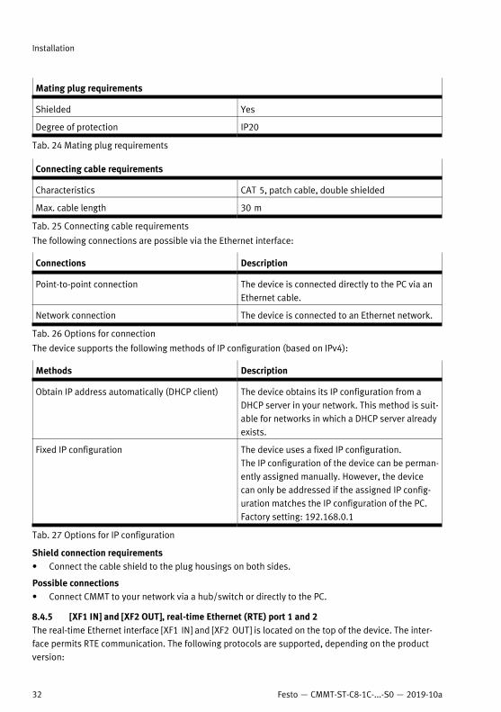
Mating plug requirements
Design VS-08-RJ45-5-Q/IP20 from Phoenix Contact orcompatible
Number of pins 8
Installation
31Festo — CMMT-ST-C8-1C-...-S0 — 2019-10a
Mating plug requirements
Shielded Yes
Degree of protection IP20
Tab. 24 Mating plug requirements
Connecting cable requirements
Characteristics CAT 5, patch cable, double shielded
Max. cable length 30 m
Tab. 25 Connecting cable requirements
The following connections are possible via the Ethernet interface:
Connections Description
Point-to-point connection The device is connected directly to the PC via anEthernet cable.
Network connection The device is connected to an Ethernet network.
Tab. 26 Options for connection
The device supports the following methods of IP configuration (based on IPv4):
Methods Description
Obtain IP address automatically (DHCP client) The device obtains its IP configuration from aDHCP server in your network. This method is suit-able for networks in which a DHCP server alreadyexists.
Fixed IP configuration The device uses a fixed IP configuration.The IP configuration of the device can be perman-ently assigned manually. However, the devicecan only be addressed if the assigned IP config-uration matches the IP configuration of the PC.Factory setting: 192.168.0.1
Tab. 27 Options for IP configuration
Shield connection requirements• Connect the cable shield to the plug housings on both sides.
Possible connections• Connect CMMT to your network via a hub/switch or directly to the PC.
8.4.5 [XF1 IN] and [XF2 OUT], real-time Ethernet (RTE) port 1 and 2The real-time Ethernet interface [XF1 IN] and [XF2 OUT] is located on the top of the device. The inter-face permits RTE communication. The following protocols are supported, depending on the productversion:
Installation
32 Festo — CMMT-ST-C8-1C-...-S0 — 2019-10a

Product variant Supported protocol
CMMT-ST-...-EC EtherCAT
CMMT-ST-...-EP EtherNet/IP
CMMT-ST-...-PN PROFINET
Tab. 28 Supported protocol
The physical level of the interface fulfils the requirements according to IEEE 802.3:2012-00. The inter-face is galvanically isolated and intended for use with limited cable lengths.2 LEDs are integrated into the RJ45 bushings. The behaviour of the LEDs depends on the bus protocol.Use is not always made of both LEDs.
Real-time Ethernet (RTE) port 1 and port 2
[XF2 OUT] and [XF1 IN] Pin Function Description
1 TX+ Transmitted data+
2 TX- Transmitted data-
3 RX+ Received data+
4 n. c.
5 n. c.
Not connected
6 RX- Received data-
7 n. c.
8 n. c.
Not connected
Housing FE The housing is used as asupport for the cable shieldand is connected to the FE.
Tab. 29 [XF1 IN] and [XF2 OUT], RTE port 1 and 2
Mating plug requirements
Design VS-08-RJ45-5-Q/IP20 from Phoenix Contact orcompatible
Number of pins 8
Shielded Yes
Degree of protection IP20
Tab. 30 Mating plug requirements
Installation
33Festo — CMMT-ST-C8-1C-...-S0 — 2019-10a

Connecting cable requirements
Characteristics CAT 5, patch cable, double shielded
Max. cable length 30 m
Tab. 31 Connecting cable requirements
Shield connection requirements• Connect the cable shield to the plug housings on both sides.
8.5 Motor connectionThe connection [X6] is located on the front of the device. The following functions are carried out via theconnection [X6]:– Supply motor coils with current– Actuate optional holding brake of the motorAs a rule, the brakes used are holding brakes. This means the brakes are well suited to keeping themotor at a standstill. The holding brake must be designed for the load torque to be stopped. Holdingbrakes are not usually suitable for braking moving masses or loads.• Check that the holding brake used is suitable for the application.The servo drive controls the output for the holding brake automatically. Information about brake con-trol è Online help for the CMMT-ST plug-in.Pin allocation for connecting a stepper motor:
[X6] Pin Function Description Mating pluglabelling
1 A String A A
2 A/ String A/ A/
3 B String B B
4 B/ String B/ B/
5 Br+ Brake +24 V Br+
6 Br-/0 V Brake 0 V Br-/
Tab. 32 Motor phase connection for connecting a stepper motor
Installation
34 Festo — CMMT-ST-C8-1C-...-S0 — 2019-10a
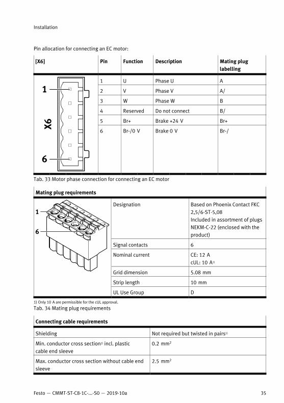
Pin allocation for connecting an EC motor:
[X6] Pin Function Description Mating pluglabelling
1 U Phase U A
2 V Phase V A/
3 W Phase W B
4 Reserved Do not connect B/
5 Br+ Brake +24 V Br+
6 Br-/0 V Brake 0 V Br-/
Tab. 33 Motor phase connection for connecting an EC motor
Mating plug requirements
Designation Based on Phoenix Contact FKC2,5/6-ST-5,08Included in assortment of plugsNEKM-C-22 (enclosed with theproduct)
Signal contacts 6
Nominal current CE: 12 AcUL: 10 A1)
Grid dimension 5.08 mm
Strip length 10 mm
UL Use Group D
1) Only 10 A are permissible for the cUL approval.
Tab. 34 Mating plug requirements
Connecting cable requirements
Shielding Not required but twisted in pairs1)
Min. conductor cross section2) incl. plasticcable end sleeve
0.2 mm2
Max. conductor cross section without cable endsleeve
2.5 mm2
Installation
35Festo — CMMT-ST-C8-1C-...-S0 — 2019-10a
Connecting cable requirements
Max. length 25 m
1) Shielded cables from Festo can be used. The shield can only be connected on the motor side.2) The conductor cross section used must be suitable for the currents that arise.
Tab. 35 Connecting cable requirements
Festo offers prefabricated motor cables as accessories è www.festo.com/catalogue.
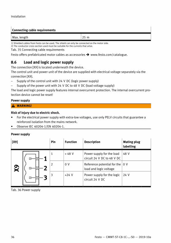
8.6 Load and logic power supplyThe connection [X9] is located underneath the device.The control unit and power unit of the device are supplied with electrical voltage separately via theconnection [X9].– Supply of the control unit with 24 V DC (logic power supply)– Supply of the power unit with 24 V DC to 48 V DC (load voltage supply)The load and logic power supply features internal overcurrent protection. The internal overcurrent pro-tection device cannot be reset!
Power supply
WARNING!
Risk of injury due to electric shock.• For the electrical power supply with extra-low voltages, use only PELV circuits that guarantee a
reinforced isolation from the mains network.• Observe IEC 60204-1/EN 60204-1.
Power supply
[X9] Pin Function Description Mating pluglabelling
1 + 48 V Power supply for the loadcircuit 24 V DC to 48 V DC
48 V
2 0 V Reference potential for theload and logic voltage
0 V
3 +24 V Power supply for the logiccircuit 24 V DC
24 V
Tab. 36 Power supply
Installation
36 Festo — CMMT-ST-C8-1C-...-S0 — 2019-10a
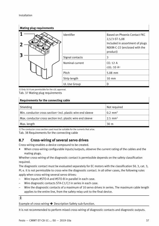
Mating plug requirements
Identifier Based on Phoenix Contact FKC2,5/3-ST-5,08Included in assortment of plugsNEKM-C-22 (enclosed with theproduct)
Signal contacts 3
Nominal current CE: 12 AcUL: 10 A1)
Pitch 5.08 mm
Strip length 10 mm
UL Use Group D
1) Only 10 A are permissible for the cUL approval.
Tab. 37 Mating plug requirements
Requirements for the connecting cable
Shielding Not required
Min. conductor cross section1) incl. plastic wire end sleeve 0.2 mm2
Max. conductor cross section incl. plastic wire end sleeve 2.5 mm2
Max. length 30 m
1) The conductor cross section used must be suitable for the currents that arise.
Tab. 38 Requirements for the connecting cable
8.7 Cross-wiring of several servo drivesCross-wiring enables a device compound to be created.• When cross-wiring configurable inputs/outputs, observe the current rating of the cables and the
mating plugs.Whether cross-wiring of the diagnostic contact is permissible depends on the safety classificationrequired.The diagnostic contact must be evaluated separately for EC motors with the classification SIL 3, cat. 3,PL e. It is not permissible to cross-wire the diagnostic contact. In all other cases, the following rulesapply when cross-wiring several servo drives:– Wire inputs #STO-A and #STO-B in parallel in each case.– Wire diagnostic contacts STA-C1/C2 in series in each case.– Wire the diagnostic contacts of a maximum of 10 servo drives in series. The maximum cable length
applies to the entire line, from the safety relay unit to the final device.
Example of cross-wiring è Description Safety sub-function.
It is not recommended to perform mixed cross-wiring of diagnostic contacts and diagnostic outputs.
Installation
37Festo — CMMT-ST-C8-1C-...-S0 — 2019-10a
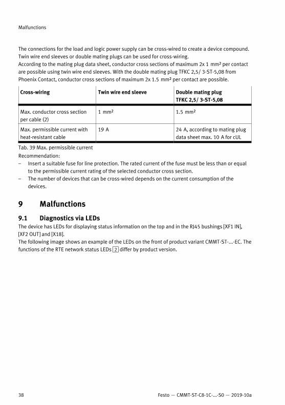
The connections for the load and logic power supply can be cross-wired to create a device compound.Twin wire end sleeves or double mating plugs can be used for cross-wiring.According to the mating plug data sheet, conductor cross sections of maximum 2x 1 mm² per contactare possible using twin wire end sleeves. With the double mating plug TFKC 2,5/ 3-ST-5,08 fromPhoenix Contact, conductor cross sections of maximum 2x 1.5 mm² per contact are possible.
Cross-wiring Twin wire end sleeve Double mating plugTFKC 2,5/ 3-ST-5,08
Max. conductor cross sectionper cable (2)
1 mm² 1.5 mm²
Max. permissible current withheat-resistant cable
19 A 24 A, according to mating plugdata sheet max. 10 A for cUL
Tab. 39 Max. permissible current
Recommendation:– Insert a suitable fuse for line protection. The rated current of the fuse must be less than or equal
to the permissible current rating of the selected conductor cross section.– The number of devices that can be cross-wired depends on the current consumption of the
devices.
9 Malfunctions
9.1 Diagnostics via LEDsThe device has LEDs for displaying status information on the top and in the RJ45 bushings [XF1 IN],[XF2 OUT] and [X18]. The following image shows an example of the LEDs on the front of product variant CMMT-ST-...-EC. Thefunctions of the RTE network status LEDs 2 differ by product version.
Malfunctions
38 Festo — CMMT-ST-C8-1C-...-S0 — 2019-10a
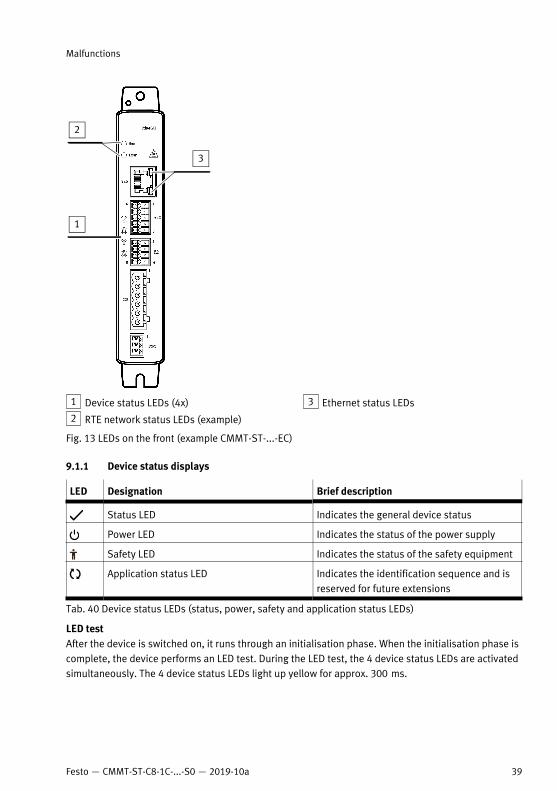
1 Device status LEDs (4x)
2 RTE network status LEDs (example)
3 Ethernet status LEDs
Fig. 13 LEDs on the front (example CMMT-ST-...-EC)
9.1.1 Device status displays
LED Designation Brief description
Status LED Indicates the general device status
Power LED Indicates the status of the power supply
Safety LED Indicates the status of the safety equipment
Application status LED Indicates the identification sequence and isreserved for future extensions
Tab. 40 Device status LEDs (status, power, safety and application status LEDs)
LED testAfter the device is switched on, it runs through an initialisation phase. When the initialisation phase iscomplete, the device performs an LED test. During the LED test, the 4 device status LEDs are activatedsimultaneously. The 4 device status LEDs light up yellow for approx. 300 ms.
Malfunctions
39Festo — CMMT-ST-C8-1C-...-S0 — 2019-10a

Status LED, display of the device status
LED Meaning
Flash-es red
An error is present.
Flash-es yel-low
A warning is present, or the servo drive is currently performing a firmware update.
Illu-min-atedyellow
The servo drive is in the initialisation phase.
Flash-esgreen
The servo drive is ready, and the power stage is switched off (Ready).
Illu-min-atedgreen
The power stage and the closed-loop controller are enabled.
Tab. 41 Status LED
Power LED, status of the power supply
LED Meaning
Illu-min-atedyellow
The logic power supply is present, but the load voltage supply is lacking or is cur-rently being measured.
Illu-min-atedgreen
The load voltage supply and the logic power supply are present.
Tab. 42 Power LED
Safety LED, functional status of the safety engineeringMalfunctions of the safety sub-function are detected and displayed in the functional device. The fol-lowing are detected:– Safety sub-function STO requested via 1 channel (discrepancy monitoring)– Plausibility check of STO channel switch-offMalfunctions are externally reported by the functional part, including via the additional communica-tion interfaces (bus, commissioning software).
Malfunctions
40 Festo — CMMT-ST-C8-1C-...-S0 — 2019-10a

LED Meaning
Flash-es red
Error in the safety part, or a safety condition has been violated.
Illu-min-atedyellow
The safety sub-function has been requested and is active.
Illu-min-atedgreen
Ready, no safety sub-function has been requested.
Tab. 43 Safety LED
Application status
LED Meaning
Flash-esaltern-atelybetw-eenred,yellowandgreen
Identification sequence active (for optical identification of the device in a network),which can be activated via the parameterisation software
Flash-es yel-low
Lightsupyellow
Flash-esgreen
Lightsupgreen
Reserved for future extensions
Tab. 44 Application status LED
Malfunctions
41Festo — CMMT-ST-C8-1C-...-S0 — 2019-10a

Special function of the start program (bootloader) during firmware updatesWhen the bootloader starts the update procedure, the status LED flashes yellow at half-second inter-vals. The power LED, safety LED and application status LED remain dark.If an error occurs during a firmware update, the status LED flashes red at one-second intervals. Thefrequency of flashing corresponds to the error number specified in the following table. After flashing,there is a pause of 3 s. Then the procedure repeats.
Error number Description
1 The start program has detected a CRC error in the firmware after switching on.
2 The start program has detected a CRC error in the start program after switching on.
3 The start program is supposed to update the firmware but has detected an error inthe system update file.
4 The start program is supposed to update itself and the firmware but has detected adefective start program in the system update file.
5 The start program cannot access the file system or the system update file, or thesystem update file is defective.
Tab. 45 Error messages of the start program (bootloader)
9.1.2 Interface status [X18]
LEDs at [X18]; connection status of the Ethernet interface
LED Meaning (upper LED)
Off Interface is deactivated.
Lightsupgreen
Interface is activated.
Tab. 46 Upper LED at [X18]
LED Meaning (lower LED)
Off No communication activity
Flash-es yel-low
Communication activity detected.
Tab. 47 Lower LED at [X18]
Malfunctions
42 Festo — CMMT-ST-C8-1C-...-S0 — 2019-10a
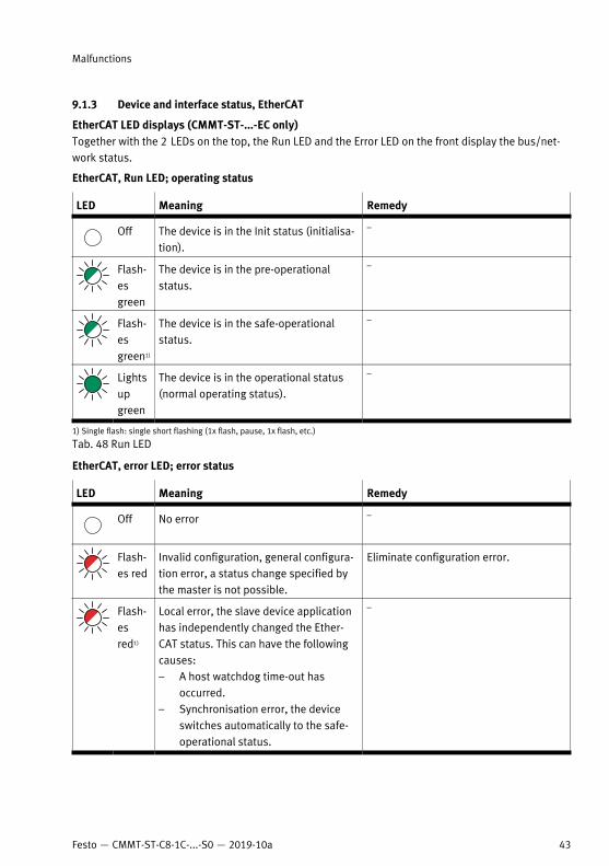
9.1.3 Device and interface status, EtherCAT
EtherCAT LED displays (CMMT-ST-...-EC only)Together with the 2 LEDs on the top, the Run LED and the Error LED on the front display the bus/net-work status.
EtherCAT, Run LED; operating status
LED Meaning Remedy
Off The device is in the Init status (initialisa-tion).
–
Flash-esgreen
The device is in the pre-operationalstatus.
–
Flash-esgreen1)
The device is in the safe-operationalstatus.
–
Lightsupgreen
The device is in the operational status(normal operating status).
–
1) Single flash: single short flashing (1x flash, pause, 1x flash, etc.)
Tab. 48 Run LED
EtherCAT, error LED; error status
LED Meaning Remedy
Off No error –
Flash-es red
Invalid configuration, general configura-tion error, a status change specified bythe master is not possible.
Eliminate configuration error.
Flash-esred1)
Local error, the slave device applicationhas independently changed the Ether-CAT status. This can have the followingcauses:– A host watchdog time-out has
occurred.– Synchronisation error, the device
switches automatically to the safe-operational status.
–
Malfunctions
43Festo — CMMT-ST-C8-1C-...-S0 — 2019-10a
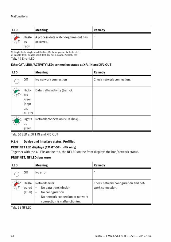
LED Meaning Remedy
Flash-esred2)
A process data watchdog time-out hasoccurred.
–
1) Single flash: single short flashing (1x flash, pause, 1x flash, etc.)2) Double flash: double short flash (2x flash, pause, 2x flash, etc.)
Tab. 49 Error LED
EtherCAT, LINK/ACTIVITY LED; connection status at XF1 IN and XF2 OUT
LED Meaning Remedy
Off No network connection Check network connection.
Flick-ersgreen(appr-ox.10 Hz)
Data traffic activity (traffic). –
Lightsupgreen
Network connection is OK (link). –
Tab. 50 LED at XF1 IN and XF2 OUT
9.1.4 Device and interface status, ProfiNet
PROFINET LED displays (CMMT-ST-...-PN only)Together with the 4 LEDs on the top, the NF LED on the front displays the bus/network status.
PROFINET, NF LED; bus error
LED Meaning Remedy
Off No error –
Flash-es red(2 Hz)
Network error– No data transmission– No configuration– No network connection or network
connection is malfunctioning
Check network configuration and net-work connection.
Tab. 51 NF LED
Malfunctions
44 Festo — CMMT-ST-C8-1C-...-S0 — 2019-10a
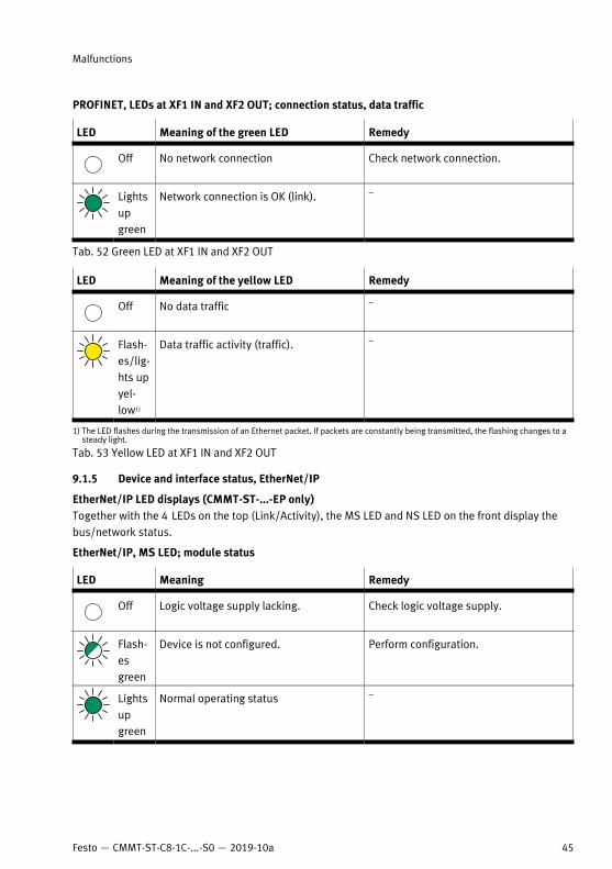
PROFINET, LEDs at XF1 IN and XF2 OUT; connection status, data traffic
LED Meaning of the green LED Remedy
Off No network connection Check network connection.
Lightsupgreen
Network connection is OK (link). –
Tab. 52 Green LED at XF1 IN and XF2 OUT
LED Meaning of the yellow LED Remedy
Off No data traffic –
Flash-es/lig-hts upyel-low1)
Data traffic activity (traffic). –
1) The LED flashes during the transmission of an Ethernet packet. If packets are constantly being transmitted, the flashing changes to asteady light.
Tab. 53 Yellow LED at XF1 IN and XF2 OUT
9.1.5 Device and interface status, EtherNet/IP
EtherNet/IP LED displays (CMMT-ST-...-EP only)Together with the 4 LEDs on the top (Link/Activity), the MS LED and NS LED on the front display thebus/network status.
EtherNet/IP, MS LED; module status
LED Meaning Remedy
Off Logic voltage supply lacking. Check logic voltage supply.
Flash-esgreen
Device is not configured. Perform configuration.
Lightsupgreen
Normal operating status –
Malfunctions
45Festo — CMMT-ST-C8-1C-...-S0 — 2019-10a

LED Meaning Remedy
Flash-esred/g-reen
Device performs a self-test. –
Flash-es red
Rectifiable error, possibly a configura-tion error
Check configuration.
Lightsup red
Error cannot be rectified Contact Festo Service è www.festo.com.
Tab. 54 MS LED
EtherNet/IP, NS LED; network status
LED Meaning Remedy
Off The device is switched off or has no IPaddress.
Switch on device or check IP address.
Flash-esgreen
The device has an IP address but no CIPconnection.It may be that the device is not assignedto a master/scanner.
Eliminate configuration error.
Lightsupgreen
Normal operating status.The device is online and has a CIP con-nection.
–
Flash-esred/g-reen
Device performs a self-test. –
Flash-es red
One or more I/O connections are in thetime-out status.
Check the physical connection to themaster/scanner.
Lightsup red
The IP address of the device has alreadybeen assigned.
Check and correct IP addresses in thenetwork.
Tab. 55 NS LED
EtherNet/IP, LED at XF1 IN and XF2 OUT; connection status, data traffic
LED Meaning of the green LED Remedy
Off No network connection Check network connection.
Malfunctions
46 Festo — CMMT-ST-C8-1C-...-S0 — 2019-10a

LED Meaning of the green LED Remedy
Lightsupgreen
Network connection is OK (link). –
Tab. 56 Green LED at XF1 IN and XF2 OUT
LED Meaning of the yellow LED Remedy
Off No data traffic –
Flick-ersyellow
Data traffic activity. –
Tab. 57 Yellow LED at XF1 IN and XF2 OUT
10 DisassemblyWARNING!
Danger of burns from hot housing surfaces.Metallic housing parts can reach high temperatures during operation.Contact with metal housing parts can cause burn injuries.• Do not touch metallic housing parts.• After the power supply is switched off, let the device cool down to room temperature.
Disassemble in reverse order of installation.
Before disassembly1. Switch off the power supply at the main switch.2. Secure the system against accidental reactivation.3. Let the device cool down to room temperature.4. Disconnect all electrical cables.
Disassembly for wall mounting• Loosen retaining screws (2x) and remove the device from the mounting surface.
Disassembly for H-rail mounting• Carefully tilt the servo drive upwards and remove it from the H-rail.
Disassembly
47Festo — CMMT-ST-C8-1C-...-S0 — 2019-10a
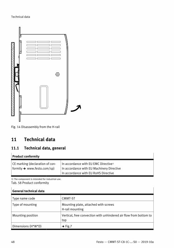
Fig. 14 Disassembly from the H-rail
11 Technical data
11.1 Technical data, general
Product conformity
CE marking (declaration of con-formity è www.festo.com/sp)
In accordance with EU EMC Directive1)
In accordance with EU Machinery DirectiveIn accordance with EU RoHS Directive
1) The component is intended for industrial use.
Tab. 58 Product conformity
General technical data
Type name code CMMT-ST
Type of mounting Mounting plate, attached with screwsH-rail mounting
Mounting position Vertical, free convection with unhindered air flow from bottom totop
Dimensions (H*W*D) è Fig.7
Technical data
48 Festo — CMMT-ST-C8-1C-...-S0 — 2019-10a

General technical data
Product weight [kg] Approx. 0.35
Displays – Device status display: 4 LEDs– Bus-specific status:
– CMMT-ST-...-EC: 2 LEDs (Run, Error)– CMMT-ST-...-EP: 2 LEDs (MS, NS)– CMMT-ST-...-PN: 1 LED (NF)
– RTE network status LEDs [X1F IN], [X1F OUT]:– CMMT-ST-...-EC: 2 LEDs– CMMT-ST-...-EP: 4 LEDs– CMMT-ST-...-PN: 4 LEDs
– Ethernet status LEDs [X18]: 2 LEDs
Parameterisation interface – [X18], Ethernet; parameterisation and configuration via com-missioning software (è www.festo.com/sp)
– [XF1 IN], [XF2 OUT], RT Ethernet; parameterisation and con-figuration via bus protocol
RT Ethernet protocol CMMT-ST-...-EC: EtherCATCMMT-ST-...-EP: EtherNet/IPCMMT-ST-...-PN: PROFINET
Tab. 59 General technical data
Ambient conditions, transport in original packaging or in control cabinet
Transport temperature [°C] −25 … +70
Relative humidity [%] 5 … 95 (non-condensing)
Max. transportationduration
[d] 56 at 70 °C
Permissible altitude [m] 12,000 (above sea level) for 12 h
Vibration resistance Vibration test and free fall in packaging in accordance withEN 61800-2
Tab. 60 Ambient conditions, transport
Ambient conditions, storage in original packaging or in control cabinet
Storage temperature [°C] −25 … +55
Relative humidity [%] 5 … 95 (non-condensing)
Permissible altitude [m] 3000 (above sea level)
Tab. 61 Ambient conditions, storage
Technical data
49Festo — CMMT-ST-C8-1C-...-S0 — 2019-10a

Ambient conditions, operation
Ambient temperature [°C] 0 … +50
Cooling Through ambient air in the control cabinet
Relative humidity [%] 5 … 90 (non-condensing)No corrosive media permitted near the device
Permissible setup alti-tude above sea level
[m] 0 … 2000Operation above 2000 m is not permitted!
Degree of protection IP20Use in a control cabinet with at least IP54, design as “closedelectrical operating area” in accordance with EN 61800-5-1,Chap. 3.5
Protection class III (safety extra-low voltage)
Overvoltage category I
Pollution degree 2
Vibration resistance in accord-ance with
EN 61800-5-1 and EN 61800-2
Shock resistance in accordancewith
EN 61800-2
EMC in accordance with EN 61800-5-2
Tab. 62 Ambient conditions, operation
Service life
Service life of thedevice at rated load
[h] 25000Dependent on the required current and the ambient temperaturein compliance with the necessary mounting clearances andderating è Fig.15
Tab. 63 Service life
Materials
Housing Hood: plastic Akulon K223-KMV6Cooling profile: sheet steel
Tab. 64 Materials
Technical data
50 Festo — CMMT-ST-C8-1C-...-S0 — 2019-10a
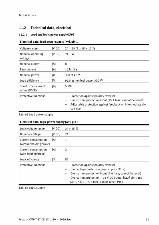
11.2 Technical data, electrical
11.2.1 Load and logic power supply [X9]
Electrical data, load power supply [X9], pin 1
Voltage range [V DC] 24 – 15 % … 48 + 15 %
Nominal operatingvoltage
[V DC] 24 … 48
Nominal current [A] 8
Peak current [A] 10 for 3 s
Nominal power [W] 300 at 48 V
Load efficiency [%] 96.5 at nominal power 300 W
Short circuit currentrating (SCCR)
[A] 5000
Protective functions – Protection against polarity reversal– Overcurrent protection input (15 A fuse, cannot be reset)– Adjustable protection against feedback on intermediate cir-
cuit rise
Tab. 65 Load power supply
Electrical data, logic power supply [X9], pin 3
Logic voltage range [V DC] 24 ± 15 %
Nominal voltage [V DC] 24
Current consumption(without holding brake)
[A] 1
Current consumption(with holding brake)
[A] 2
Logic efficiency [%] 82
Protective functions – Protection against polarity reversal– Overvoltage protection (from approx. 32 V)– Overcurrent protection input (4 A fuse, cannot be reset)– Overcurrent protection + 24 V DC output [X1A] pin 1 and
[X1C] pin 1 (0.5 A fuse, can be reset, PTC)
Tab. 66 Logic supply
Technical data
51Festo — CMMT-ST-C8-1C-...-S0 — 2019-10a

11.2.2 Power specifications, motor connection [X6]
Power specifications during operation
Nominal output current [A] 8
Tab. 67 Power specifications during operation
Any derating that may be necessary as a function of the ambient temperature è Fig.15.The CMMT-ST does not have any built-in electronic overload and overtemperature protection functionsfor the motor. An I²t monitoring function can be parameterised for the motor current in order to protectthe motor, using the device-specific plug-in, for example.
Power unit temperature monitoring (parameterisable)
Warning [°C] 85
Shutdown [°C] > 95
Tab. 68 Temperature monitoring
Output of holding brake at [X6]
Design High-side switch
Max. continuous out-put current
[A] 1 (parameterisable holding current reduction)
Max. voltage drop from+ 24 V input at connec-tion [X9] to brake out-put at [X6]
[V DC] 1
Protective functions Short-circuit and overload-protected
Tab. 69 Output of holding brake at [X6]
11.2.3 Encoder interfaces [X2]
Digital incremental encoder at [X2]
Parameterisable no. ofencoder pulses
1 … 262144 periods/revolution (18 bit)
Angle resolution/inter-polation
4-fold evaluation as 4 steps (2 bits) per period
Tracking signals A/B/N RS422/485
Input impedanceA/B/N
[Ω] 120 (differential input)
[V] 5.25Output supply
[A] Max. 0.5, unregulated (no Sense cable)
Technical data
52 Festo — CMMT-ST-C8-1C-...-S0 — 2019-10a

Digital incremental encoder at [X2]
Support: mechanicalmultiturn encoder
No
Support: battery-buf-fered multiturnencoder
No
Support: encoder para-meter memory
No
Encoder signal monit-oring
No, no direct encoder signal monitoring
Protective function No overload protection
Tab. 70 Digital incremental encoder at [X2]
Absolut encoder with BiSS C protocol
[V] 5.25Supply
[A] 0.5
Resolution can be parameterised - default: 16 bit
Support: mechanicalmultiturn encoder
No
Support: battery-buf-fered multiturnencoder
No
Support: encoder para-meter memory
Yes
Encoder signal monit-oring
Yes
Protective function No overload protection
Tab. 71 Encoder with BiSS-C protocol
11.2.4 Digital inputs and outputs [X1A]
Control inputs #STO-A and #STO-B at [X1A]
Nominal voltage [V DC] 24 (relative to 0 V at X9)
Permissible voltagerange1)
[V DC] –3 … 30
Max. input voltage,high level (UH max)
[V] 28.8
Technical data
53Festo — CMMT-ST-C8-1C-...-S0 — 2019-10a
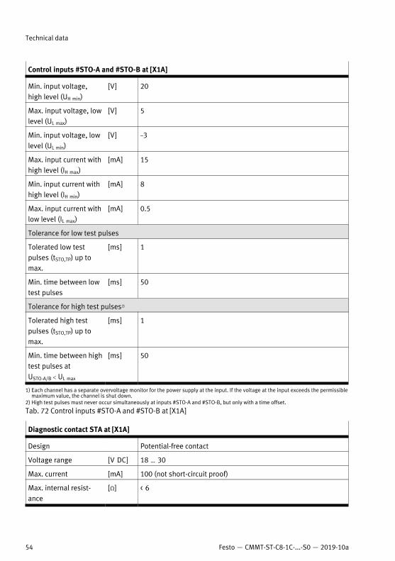
Control inputs #STO-A and #STO-B at [X1A]
Min. input voltage,high level (UH min)
[V] 20
Max. input voltage, lowlevel (UL max)
[V] 5
Min. input voltage, lowlevel (UL min)
[V] –3
Max. input current withhigh level (IH max)
[mA] 15
Min. input current withhigh level (IH min)
[mA] 8
Max. input current withlow level (IL max)
[mA] 0.5
Tolerance for low test pulses
Tolerated low testpulses (tSTO,TP) up tomax.
[ms] 1
Min. time between lowtest pulses
[ms] 50
Tolerance for high test pulses2)
Tolerated high testpulses (tSTO,TP) up tomax.
[ms] 1
Min. time between hightest pulses atUSTO-A/B < UL max
[ms] 50
1) Each channel has a separate overvoltage monitor for the power supply at the input. If the voltage at the input exceeds the permissiblemaximum value, the channel is shut down.
2) High test pulses must never occur simultaneously at inputs #STO-A and #STO-B, but only with a time offset.
Tab. 72 Control inputs #STO-A and #STO-B at [X1A]
Diagnostic contact STA at [X1A]
Design Potential-free contact
Voltage range [V DC] 18 … 30
Max. current [mA] 100 (not short-circuit proof)
Max. internal resist-ance
[Ω] < 6
Technical data
54 Festo — CMMT-ST-C8-1C-...-S0 — 2019-10a

Diagnostic contact STA at [X1A]
Off-state current (con-tact open)
[µA] < 2
Closing reaction timetSTA,Rise
[ms] . 80 (typ. 20)
Opening reaction timetSTA,Fall
[ms] ≤ 50 (typ. 30)
Galvanic isolation Via optocoupler
Protective functions Overvoltage-resistant up to 60 V DC
Tab. 73 Diagnostic contact STA-C1/C2 at [X1A]
Digital inputs without safety inputs at [X1A]
Specification Based on type 3 to EN 61131-2; deviating current consumption
Nominal voltage [V DC] 24
Permissible voltagerange
[V DC] −3 … 30
Min. input current intransition range (IT min)
[mA] 1.5
Logic PNP NPN
Max. input voltage(UH max), high level
[V] 30 5
Min. input voltage(UH min), high level
[V] Typically 11max. 13
Typically 0
Max. input voltage(UL max), low level
[V] 5 30
Min. input voltage(UL min), low level
[V] –3 11
Max. input current(IH max) with high level
[mA] 15 –4
Min. input current(IH min) with high level
[mA] 5 –10
Max. input current(IL max) with low level
[mA] 15 3.43
Data for inputs Basic In 1 and Basic In 2 (Capture)
Delay time in the hard-ware
[µs] < 2
Technical data
55Festo — CMMT-ST-C8-1C-...-S0 — 2019-10a

Digital inputs without safety inputs at [X1A]
Min. permissible pulselength (high or low)
[µs] 10
Time resolution/accur-acy (high or low)
[µs] < 1
Data for the input CTRL-EN (power stage enable/acknowledge error)
Delay time in the hard-ware
[µs] < 10
Tab. 74 Digital inputs without safety inputs – part 1
Digital outputs at [X1A] (X1A.9 and X1A.10)
Design PNP operation: high-side switchNPN operation: low-side switch
Characteristics – Freely configurable– Not galvanically isolated
Voltage range [V DC] 0 … 30
Permissible output cur-rent
[mA] 100
Max. voltage loss [V] < 3
Protective function – Short-circuit proof– Feedback-proof– Overvoltage-resistant up to 60 V– Automatic switch-off in event of excessive temperature
Tab. 75 Digital outputs at [X1A]
Voltage for supplying external components at [X1A.1]
Output voltage [V DC] +24 (internal logic voltage)
Use Supply of potential-free outputs of the PLC, e.g. a potential-freerelay contact for the CTRL-EN input
Max. output current [mA] 100
Protective function – Short circuit to 0 V– Feedback-proof
Tab. 76 Voltage for supplying external components at [X1A]
Technical data
56 Festo — CMMT-ST-C8-1C-...-S0 — 2019-10a
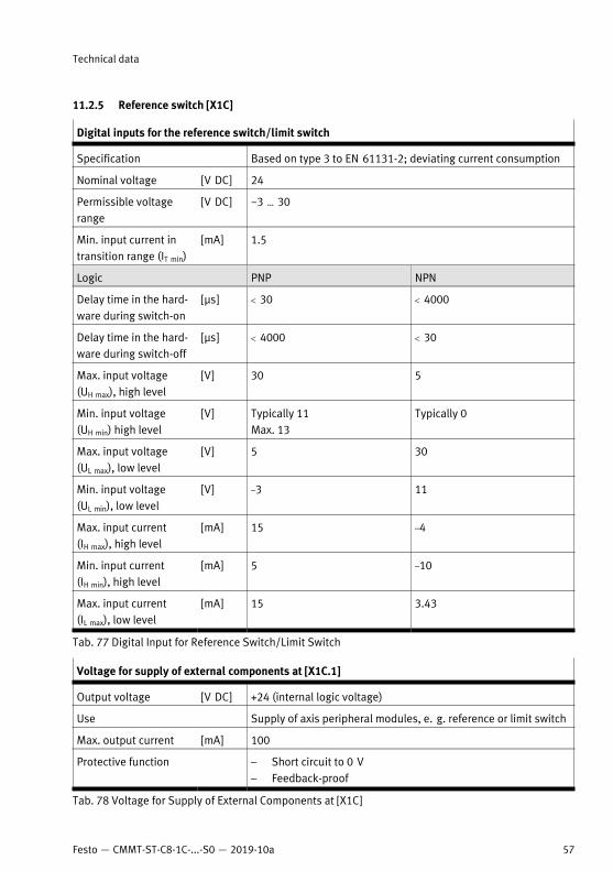
11.2.5 Reference switch [X1C]
Digital inputs for the reference switch/limit switch
Specification Based on type 3 to EN 61131-2; deviating current consumption
Nominal voltage [V DC] 24
Permissible voltagerange
[V DC] −3 … 30
Min. input current intransition range (IT min)
[mA] 1.5
Logic PNP NPN
Delay time in the hard-ware during switch-on
[µs] < 30 < 4000
Delay time in the hard-ware during switch-off
[µs] < 4000 < 30
Max. input voltage(UH max), high level
[V] 30 5
Min. input voltage(UH min) high level
[V] Typically 11Max. 13
Typically 0
Max. input voltage(UL max), low level
[V] 5 30
Min. input voltage(UL min), low level
[V] –3 11
Max. input current(IH max), high level
[mA] 15 –4
Min. input current(IH min), high level
[mA] 5 –10
Max. input current(IL max), low level
[mA] 15 3.43
Tab. 77 Digital Input for Reference Switch/Limit Switch
Voltage for supply of external components at [X1C.1]
Output voltage [V DC] +24 (internal logic voltage)
Use Supply of axis peripheral modules, e. g. reference or limit switch
Max. output current [mA] 100
Protective function – Short circuit to 0 V– Feedback-proof
Tab. 78 Voltage for Supply of External Components at [X1C]
Technical data
57Festo — CMMT-ST-C8-1C-...-S0 — 2019-10a

11.2.6 Standard Ethernet [X18], parameterisation interface
Standard Ethernet [X18], parameterisation interface
Design To IEEE 802.3:2012-001)
Connection design RJ45
Transmission rate [Mbit/s] 10/100 (full/half duplex)
Supported protocols TCP/IP
IP address set at fact-ory (presetting)
192.168.0.1
1) Restriction: The interface is galvanically isolated and intended for use with limited cable lengths.
Tab. 79 Standard Ethernet [X18]
11.2.7 Real-time Ethernet [XF1 IN], [XF2 OUT]
Real-time Ethernet [XF1 IN], [XF2 OUT]
Design RTE communication, physical level toIEEE 802.3:2012-001)
Bus connection design[XF1 IN]
RJ45
Bus connection design[XF2 OUT]
RJ45
Max. transmission rate [Mbit/s] 100
Bus protocol EtherCAT: CMMT-ST-...-EC
Protocol – CoE (CANopen over EtherCAT)– EoE (Ethernet over EtherCATEtherCAT)– FoE (File Access over EtherCAT)
Communication profile – CiA 402
Bus protocol EtherNet/IP: CMMT-ST-...-EP
Protocol – Implicit messaging– Explicit messaging
Bus protocol PROFINET: CMMT-ST-...-PN
Protocol – PROFINET RT– PROFINET IRT
Drive profile – PROFIdrive– PROFIenergy
1) Restriction: The interface is galvanically isolated and intended for use with limited cable lengths.
Tab. 80 Real-time Ethernet [XF1 IN], [XF2 OUT]
Technical data
58 Festo — CMMT-ST-C8-1C-...-S0 — 2019-10a

11.3 Characteristic curvesRequired power reductionMounting clearances may be required at output currents > 4.6 A to ensure the device reaches its spe-cified service life. The required mounting clearances depend on the ambient temperature and the out-put current.Mounting clearances from 0 mm are possible for a device compound consisting of several servo drivesCMMT-ST. The following characteristic curves show the maximum permissible effective currents forthe lateral mounting clearances 0 mm, 3 mm, 10 mm and 15 mm.
1 Mounting clearance 15 mm
2 Mounting clearance 10 mm
3 Mounting clearance 3 mm
4 Mounting clearance 0 mm
Fig. 15 Power reduction as a function of the ambient temperature and mounting clearance
11.4 Technical data UL/CSA certificationIn combination with the UL inspection mark on the product, the information in this section must alsobe observed in order to comply with the certification conditions of Underwriters Laboratories Inc. (UL)for USA and Canada.
UL/CSA certification information
Product category code NMMS / NMMS7 (Power Conversion Equipment)
File number E331130_Vol-3_Sec-1
Considered standards UL 61800-5-1 Adjustable Speed Electrical Power Drive SystemsCSA C22.2 No. 274-17 – Adjustable Speed Drive
Technical data
59Festo — CMMT-ST-C8-1C-...-S0 — 2019-10a

UL/CSA certification information
UL mark
UL control number 4PU8
Tab. 81 UL/CSA certification information
Electrical Data and Ambient Conditions UL
Overvoltage category II
Pollution degree 2 (or better)
Protection class Class III (SELV/PELV)
Installation site for indoor use only
Max. installation height 2000 m
SCCR (short circuit current rating) 5000 A
Tab. 82 Electrical Data and Ambient Conditions UL/CSA
– Use 60/75 °C copper conductors only:– [X6], motor connection– [X9], load and logic voltage
– Use in an environment with pollution degree 2 (or better).– Maximum surrounding air temperature: 50 °C – With correct parameterisation of the nominal motor current, the motor is protected against over-
loading by the I²t monitoring function.– For the load voltage supply, the use of a suitable fuse is recommended in accordance with the fol-
lowing table.
Fuse requirements
Overcurrent protective device UL Listed JDDZ class K5
Max. permissible ratedcurrent
[A] 30
Min. short circuit cur-rent rating SCCR ofmains fuse
[kA] 5
Min. rated voltage [V DC] 125
Tab. 83 Fuse requirements for load voltage supply
Example: Littelfuse NLN 30, Bussmann NON-30
Technical data
60 Festo — CMMT-ST-C8-1C-...-S0 — 2019-10a


© 2019 all rights reserved to Festo SE & Co. KG
Copyright:Festo SE & Co. KG Ruiter Straße 82 73734 Esslingen Germany
+49 711 347-0
www.festo.comInternet:
Phone:


![Festo A5 1spaltig · 4. Transfer the automation project to the higher-order controller. Behaviour of the display components of the module after error-free commissioning [MD] [SD]](https://img.pdfslide.us/doc/110x75/5f6210b13e0a903ade098a27/festo-a5-1spaltig-4-transfer-the-automation-project-to-the-higher-order-controller.jpg)