Embed Size (px)
Citation preview
International Journal of Applied Engineering Research ISSN 0973-4562 Volume 12, Number 23 (2017) pp. 13023-13036
© Research India Publications. http://www.ripublication.com
13023
Ferroconcrete Dismantling Technique using Induction Heating
MyungKwan, Lim 1 and Hyeonggil Choi 2, *
1Assistant Professor, Dr., Department of Architectural Engineering, Songwon University, Gwangju Metropolitan City, Republic of Korea.
2Assistant Professor, Graduate School of Engineering, Muroran Institute of Technology, Japan. *Correspondence Author
Orcid: 0000-0002-0493-4439 & IDsScopus Author ID: 57192715396
Abstract
To increase the quality of recycling, a new demolition
technique is required that can work in parallel with existing
crushing methods, which use large equipment with high
crushing efficiency. Moreover, the efficient collection of the
remains from the fractional dismantling method needs to be
considered based on its procedure, and the technology for
partial dismantling that is efficient in remodelling,
maintenance, and reinforcement has to be developed. In this
study, the temperature-increasing characteristics of rebars
inside ferroconcrete with respect to their arrangement was
investigated by partial rapid heating through high-frequency
induction heating. Based on this, the chemical and physical
vulnerability characteristics of ferroconcrete due to the
thermal conduction generated on the rebar surface and the
cracks caused by the thermal expansion pressure of the rebar
were verified. In addition, the objective of this study was to
verify the applicability of the technology by specifying the
vulnerability range of ferroconcrete based on the heating range
with adequate consumption of energy.
Keywords: Recycling; Ferroconcrete; Heat Induction; Ease to
Scrap; Weakening
INTRODUCTION
Recently, the use of fractional dismantling construction for
remodelling, maintenance, and reinforcement works has
increased rapidly. Therefore, the development and application
of new techniques for damage prevention and safety
enhancement of existing structures is essential [1,2]. By
promoting development in the current dismantling industry,
the safety of dismantling construction, reduction in
environmental pollution, proper processing of generated
wastes, and improvement of recycling rate could be achieved
[3].
This study aims to develop a technique for fractionally
dismantling ferroconcrete structures using high-frequency
induction heating technique and a selective heating using
rebars inside ferroconcrete as a conductive resistant. This
method could decrease the noise and pollution associated with
ferroconcrete dismantling, and the energy usage could be
reduced by increasing the rebar collection rate inside the
separated ferroconcrete members of the framework. Moreover,
the recycle process could be minimised, and the recycling rate
of construction wastes could be improved.
TECHNICAL OVERVIEW
Heating mechanism of internal rebar by high-frequency
induction heating (Joule heating)
The high-frequency heating methods include high-frequency
induction heating and high-frequency dielectric heating. The
dielectric heating enables uniform internal heating and
although it can heat selectively the space under an electric
field, permittivity might vary significantly during the heating.
Because it requires high frequency power compared to
induction heating, it requires a power conversion device such
as an inverter. The induction heating is a method of heating an
object such as metals by using the electrical energy
transformed from the high frequency current transport
conductor, which is the induction coil.
When an alternating current flows in the coil, a magnetic force
of varying strength is generated along the line of the coil, as
shown in Figures 1 and 2. If a metal conductor is placed near
this magnetic field, Eddy currents are induced inside the
metal. and because the metal has an electrical resistance, Joule
heat is generated of power equal to the square of the current.
As only the metal is heated by this phenomenon, there is no
danger of temperature increase in other areas [4,5].
Magnetic flux ϕ depending on alternating current i1
i1
φ
Eddy current
International Journal of Applied Engineering Research ISSN 0973-4562 Volume 12, Number 23 (2017) pp. 13023-13036
© Research India Publications. http://www.ripublication.com
13024
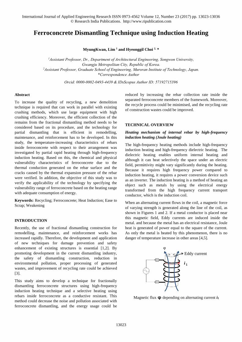
Induced current (Eddy Current i2)
Figure 1: Mechanism of high-frequency induction heating [8]
Figure 2: Thermal model of steel reinforcement based on
high-frequency induction heating [8]
Heating model of rebar using high-frequency induction
heating
As previously mentioned, if an alternating current flows in the
induction coil, an Eddy current is generated, and the metal is
heated. In this case, the Eddy current acts as a heat source
whose strength depends on the electrical resistance of the
metal.
In the case of magnetic substance, the efficiency of the heating
surface gets higher because the depth of penetration becomes
shallow depending on the increase of relative permeability. In
case of using steel reinforcement with relatively higher
permeability, localized heating on the surface of steel
reinforcement is possible because induced current is
concentrated on the areas facing the heating coil when the
magnetic field occurred from the coil is absorbed into the
surface of the metal. Selective partial heating can be achieved
in the induction heating method because the range of the
magnetic field can be adjusted by changing the diameter of the
induction coil [6, 7, 8].
VULNERABILITY CHARACTERISTIC OF
FERROCONCRETE USING HIGH-FREQUENCY
INDUCTION HEATING
Overview of experiment
In this study, the vulnerability characteristics of ferroconcrete
are examined using a high-frequency induction heating
method. As shown in Table 1 below, the experiments were
performed using 3 W/C compositions, 4 varying lengths of
rebar, and 4 heating distances at two different conditions of air
dry condition and absolute dry condition. For each
combination of experimental conditions, 3 test specimens
were made, and all of the experiments were performed based
on a ferroconcrete that is 28 days old.
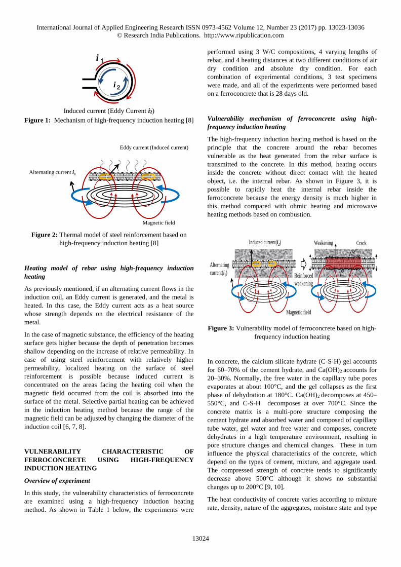
Vulnerability mechanism of ferroconcrete using high-
frequency induction heating
The high-frequency induction heating method is based on the
principle that the concrete around the rebar becomes
vulnerable as the heat generated from the rebar surface is
transmitted to the concrete. In this method, heating occurs
inside the concrete without direct contact with the heated
object, i.e. the internal rebar. As shown in Figure 3, it is
possible to rapidly heat the internal rebar inside the
ferroconcrete because the energy density is much higher in
this method compared with ohmic heating and microwave
heating methods based on combustion.
Figure 3: Vulnerability model of ferroconcrete based on high-
frequency induction heating
In concrete, the calcium silicate hydrate (C-S-H) gel accounts
for 60–70% of the cement hydrate, and Ca(OH)2 accounts for
20–30%. Normally, the free water in the capillary tube pores
evaporates at about 100°C, and the gel collapses as the first
phase of dehydration at 180°C. Ca(OH)2 decomposes at 450–
550°C, and C-S-H decomposes at over 700°C. Since the
concrete matrix is a multi-pore structure composing the
cement hydrate and absorbed water and composed of capillary
tube water, gel water and free water and composes, concrete
dehydrates in a high temperature environment, resulting in
pore structure changes and chemical changes. These in turn
influence the physical characteristics of the concrete, which
depend on the types of cement, mixture, and aggregate used.
The compressed strength of concrete tends to significantly
decrease above 500°C although it shows no substantial
changes up to 200°C [9, 10].
The heat conductivity of concrete varies according to mixture
rate, density, nature of the aggregates, moisture state and type
i1
i2
Eddy current (Induced current)
Magnetic field
Alternating current i1
Induced current(i2)
Alternating
current(i1)
Magnetic field
Reinforced
weakening
Weakening Crack
International Journal of Applied Engineering Research ISSN 0973-4562 Volume 12, Number 23 (2017) pp. 13023-13036
© Research India Publications. http://www.ripublication.com
13025
of cement. In general, it was known that the heat conductivity
of concrete is 2.5–3.0 kcal/mh°C, and the heat conductivity at
high temperature it tends to decrease as the temperature
increases. Harmathy reported that moisture increased the heat
conductivity of concrete in below 100℃ [11], but Schneider
reported that usually heat conductivity gradually decreased in
all ranges of temperature as the internal temperature of
concrete increased [9].
In addition, the model equation for heat conductivity rate
according to the ENV 1994-1-2 standard and the European
Convention for Constructional Steelwork (ECCS) is given by
Equation 1 [10].
𝐾c = 2.0 − 0.24 (𝑇
120) + 0.012 (
𝑇
120)
2
× 0.86 kcal℃ hm⁄
(1)
where
𝐾c = heat conductivity rate
𝑇 = temperature
In this study, a rebar commonly used in ferroconcrete is used
as the electrically conductive object for high-frequency
induction heating. A crack is induced on the external surface
of the concrete confining the rebar by the rebar expansion
pressure caused by the high-frequency induction heating.
Moreover, the degradability of the ferroconcrete due to
chemical vulnerabilities inside the concrete is utilized in the
dismantling mechanism by conducting the high heat of the
rebar surface to the concrete that surrounds the rebar.
Experimental conditions and levels
In this experiment, the high-frequency induction heating using
a rebar as the electrically conductive object was investigated
by constructing a ferroconcrete test object. The temperature
characteristics and vulnerability of concrete with respect to the
heat conductivity were evaluated during the experiment.
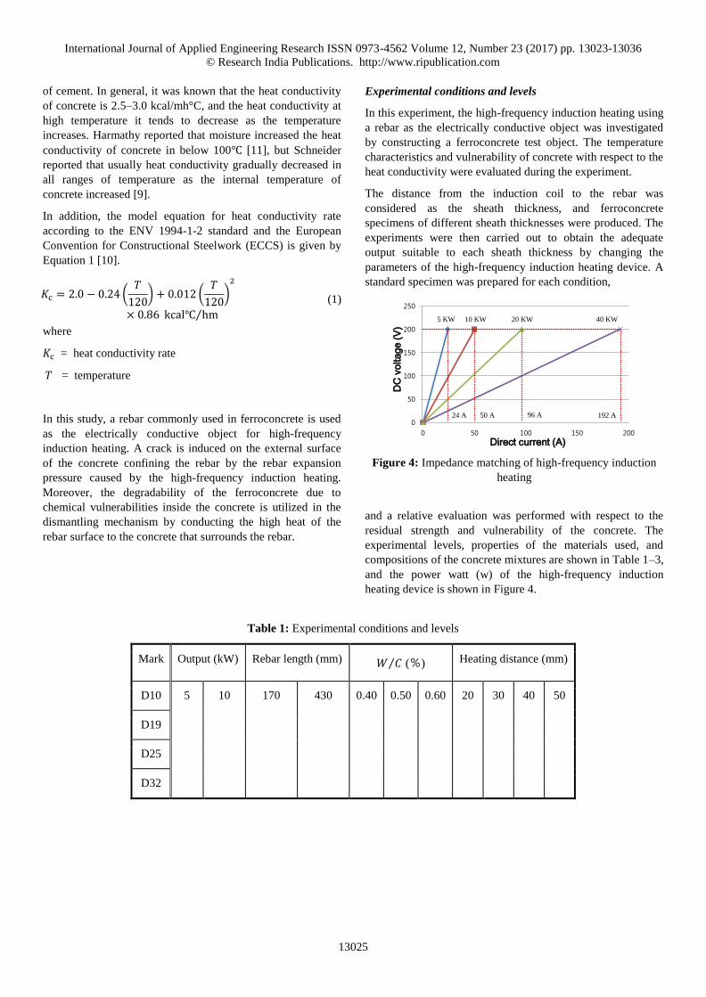
The distance from the induction coil to the rebar was
considered as the sheath thickness, and ferroconcrete
specimens of different sheath thicknesses were produced. The
experiments were then carried out to obtain the adequate
output suitable to each sheath thickness by changing the
parameters of the high-frequency induction heating device. A
standard specimen was prepared for each condition,
Figure 4: Impedance matching of high-frequency induction
heating
and a relative evaluation was performed with respect to the
residual strength and vulnerability of the concrete. The
experimental levels, properties of the materials used, and
compositions of the concrete mixtures are shown in Table 1–3,
and the power watt (w) of the high-frequency induction
heating device is shown in Figure 4.
Table 1: Experimental conditions and levels
Mark Output (kW) Rebar length (mm) 𝑊 𝐶⁄ (%) Heating distance (mm)
D10 5 10 170 430 0.40 0.50 0.60 20 30 40 50
D19
D25
D32
0
50
100
150
200
250
0 50 100 150 200
DC
vo
lta
ge
(V
)
Direct current (A)
24 A 50 A 96 A
5 KW 10 KW 20 KW 40 KW
192 A
International Journal of Applied Engineering Research ISSN 0973-4562 Volume 12, Number 23 (2017) pp. 13023-13036
© Research India Publications. http://www.ripublication.com
13026
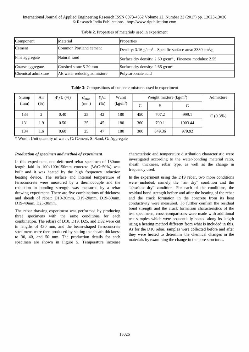
Table 2. Properties of materials used in experiment
Component Material Properties
Cement Common Portland cement Density: 3.16 g/cm3,Specific surface area: 3330 cm2/g
Fine aggregate Natural sand Surface dry density: 2.60 g/cm3,Fineness modulus: 2.55
Coarse aggregate Crushed stone 5-20 mm Surface dry density: 2.66 g/cm3
Chemical admixture AE water reducing admixture Polycarbonate acid
Table 3: Compositions of concrete mixtures used in experiment
Slump
(mm)
Air
(%)
𝑊 𝐶⁄ (%) 𝐺max (mm)
𝑆 𝑎⁄
(%)
Wunit
(kg/m3)
Weight mixture (kg/m3) Admixture
C S G
134 2 0.40 25 42 180 450 707.2 999.1 C (0.3%)
131 1.9 0.50 25 45 180 360 799.1 1003.44
134 1.6 0.60 25 47 180 300 849.36 979.92
* Wunit: Unit quantity of water, C: Cement, S: Sand, G: Aggregate
Production of specimen and method of experiment
In this experiment, one deformed rebar specimen of 180mm
length laid in 100x100x150mm concrete (W/C=50%) was
built and it was heated by the high frequency induction
heating device. The surface and internal temperature of
ferroconcrete were measured by a thermocouple and the
reduction in bonding strength was measured by a rebar
drawing experiment. There are five combinations of thickness
and sheath of rebar: D10-30mm, D19-20mm, D19-30mm,
D19-40mm, D25-30mm.
The rebar drawing experiment was performed by producing
three specimens with the same conditions for each
combination. The rebars of D10, D19, D25, and D32 were cut
in lengths of 430 mm, and the beam-shaped ferroconcrete
specimens were then produced by setting the sheath thickness
to 30, 40, and 50 mm. The production details for each
specimen are shown in Figure 5. Temperature increase
characteristic and temperature distribution characteristic were
investigated according to the water-bonding material ratio,
sheath thickness, rebar type, as well as the change in
frequency used.
In the experiment using the D19 rebar, two more conditions
were included, namely the “air dry” condition and the
“absolute dry” condition. For each of the conditions, the
residual bond strength before and after the heating of the rebar
and the crack formation in the concrete from its heat
conductivity were measured. To further confirm the residual
bond strength and the crack formation characteristics of the
test specimens, cross-comparisons were made with additional
test samples which were sequentially heated along its length
using a heating method different from what is included in this.
As for the D10 rebar, samples were collected before and after
they were heated to determine the chemical changes in the
materials by examining the change in the pore structures.

International Journal of Applied Engineering Research ISSN 0973-4562 Volume 12, Number 23 (2017) pp. 13023-13036
© Research India Publications. http://www.ripublication.com
13027
Type 1
Type 2
Figure 5: Specimen production and experimental methods
EXPERIMENTAL RESULTS AND ANALYSIS
Temperature increase of single ferroconcrete due to high-
frequency induction heating
Compression strength with respect to concrete composition:
400mm
Rebar diameter+ 30mm
鉄筋直径 + 40mm
鉄筋直径 + 50mm
D10
D19
D25
D32
Rebar diameter+ 30mm
鉄筋直径 + 40mm
鉄筋直径 + 50mm
Coil
Thermocouple
150 mm
20 mm
A
A
100 mm
100 mm
15 mm
60 mm
120 mm 60 mm140 mm
400 mm
Thermocouple
Coil
1010
Rubber cap
Reinforce
Concrete
Steel plate
Diameter: 10 mm
Diameter: 20 mm
Diameter: 30 mm
Diameter: 40 mm
International Journal of Applied Engineering Research ISSN 0973-4562 Volume 12, Number 23 (2017) pp. 13023-13036
© Research India Publications. http://www.ripublication.com
13028
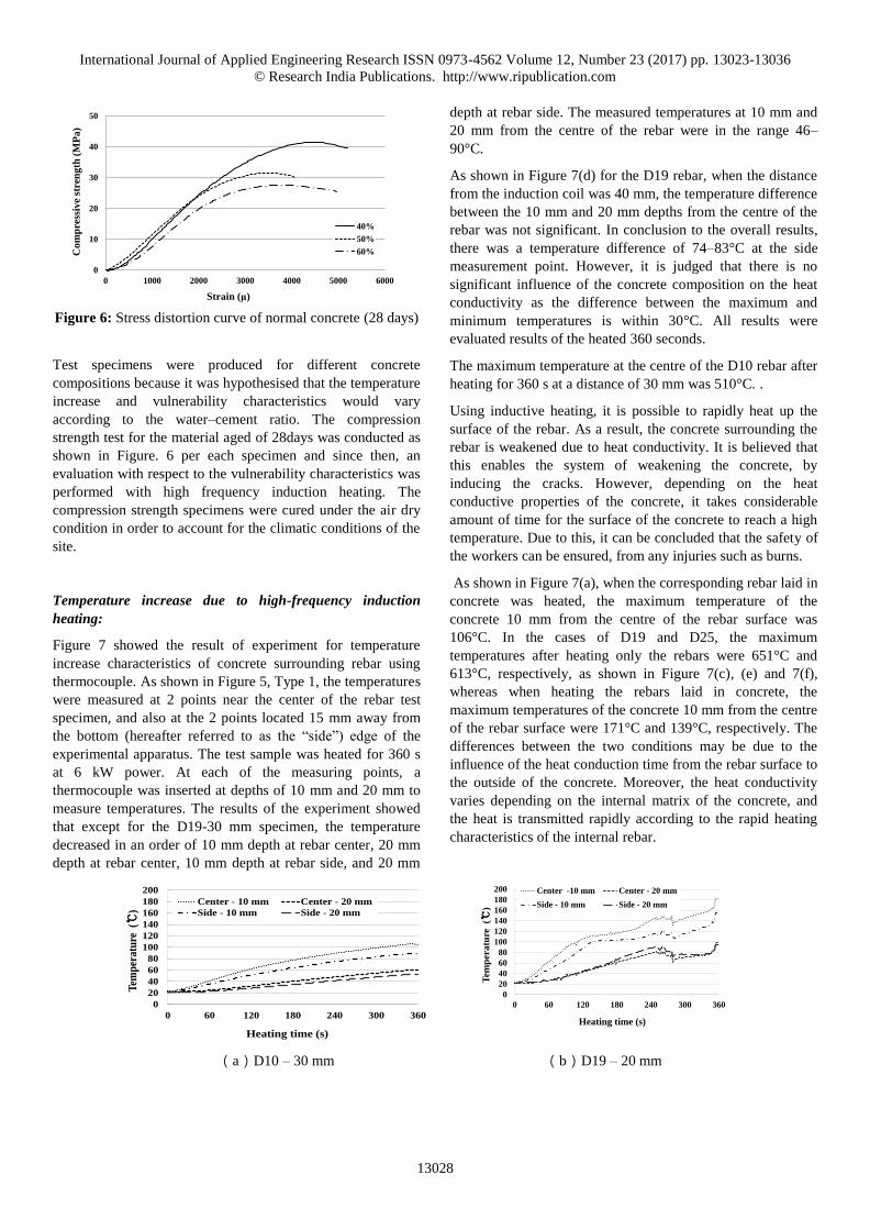
Figure 6: Stress distortion curve of normal concrete (28 days)
Test specimens were produced for different concrete
compositions because it was hypothesised that the temperature
increase and vulnerability characteristics would vary
according to the water–cement ratio. The compression
strength test for the material aged of 28days was conducted as
shown in Figure. 6 per each specimen and since then, an
evaluation with respect to the vulnerability characteristics was
performed with high frequency induction heating. The
compression strength specimens were cured under the air dry
condition in order to account for the climatic conditions of the
site.
Temperature increase due to high-frequency induction
heating:
Figure 7 showed the result of experiment for temperature
increase characteristics of concrete surrounding rebar using
thermocouple. As shown in Figure 5, Type 1, the temperatures
were measured at 2 points near the center of the rebar test
specimen, and also at the 2 points located 15 mm away from
the bottom (hereafter referred to as the “side”) edge of the
experimental apparatus. The test sample was heated for 360 s
at 6 kW power. At each of the measuring points, a
thermocouple was inserted at depths of 10 mm and 20 mm to
measure temperatures. The results of the experiment showed
that except for the D19-30 mm specimen, the temperature
decreased in an order of 10 mm depth at rebar center, 20 mm
depth at rebar center, 10 mm depth at rebar side, and 20 mm
depth at rebar side. The measured temperatures at 10 mm and
20 mm from the centre of the rebar were in the range 46–
90°C.
As shown in Figure 7(d) for the D19 rebar, when the distance
from the induction coil was 40 mm, the temperature difference
between the 10 mm and 20 mm depths from the centre of the
rebar was not significant. In conclusion to the overall results,
there was a temperature difference of 74–83°C at the side
measurement point. However, it is judged that there is no
significant influence of the concrete composition on the heat
conductivity as the difference between the maximum and
minimum temperatures is within 30°C. All results were
evaluated results of the heated 360 seconds.
The maximum temperature at the centre of the D10 rebar after
heating for 360 s at a distance of 30 mm was 510°C. .
Using inductive heating, it is possible to rapidly heat up the
surface of the rebar. As a result, the concrete surrounding the
rebar is weakened due to heat conductivity. It is believed that
this enables the system of weakening the concrete, by
inducing the cracks. However, depending on the heat
conductive properties of the concrete, it takes considerable
amount of time for the surface of the concrete to reach a high
temperature. Due to this, it can be concluded that the safety of
the workers can be ensured, from any injuries such as burns.
As shown in Figure 7(a), when the corresponding rebar laid in
concrete was heated, the maximum temperature of the
concrete 10 mm from the centre of the rebar surface was
106°C. In the cases of D19 and D25, the maximum
temperatures after heating only the rebars were 651°C and
613°C, respectively, as shown in Figure 7(c), (e) and 7(f),
whereas when heating the rebars laid in concrete, the
maximum temperatures of the concrete 10 mm from the centre
of the rebar surface were 171°C and 139°C, respectively. The
differences between the two conditions may be due to the
influence of the heat conduction time from the rebar surface to
the outside of the concrete. Moreover, the heat conductivity
varies depending on the internal matrix of the concrete, and
the heat is transmitted rapidly according to the rapid heating
characteristics of the internal rebar.
(a)D10 – 30 mm (b)D19 – 20 mm
0
10
20
30
40
50
0 1000 2000 3000 4000 5000 6000
Co
mp
ress
ive
stre
ng
th (
MP
a)
Strain (μ)
40%
50%
60%
0
20
40
60
80
100
120
140
160
180
200
0 60 120 180 240 300 360
Tem
per
atu
re (℃
)
Heating time (s)
Center - 10 mm Center - 20 mm
Side - 10 mm Side - 20 mm
0
20
40
60
80
100
120
140
160
180
200
0 60 120 180 240 300 360
Tem
per
atu
re
(℃)
Heating time (s)
Center -10 mm Center - 20 mm
Side - 10 mm Side - 20 mm

International Journal of Applied Engineering Research ISSN 0973-4562 Volume 12, Number 23 (2017) pp. 13023-13036
© Research India Publications. http://www.ripublication.com
13029
(c)D19 – 30 mm (d)D19 – 40 mm
(e)D25 – 30 mm (f) Reinforced heating results
Figure 7: Temperature increase of ferroconcrete due to induction heating (type 1) & Reinforced heating results
However, since it takes a time to transfer the heat that was
occurred inside the rebar to the surface, which was caused by
evaporation of the internal free water, the heat produced on the
surface of the rebar is high at the concrete that surrounds the
rebar while the heat at the surface of concrete is lower.
In this experiment, the 450mm ferroconcrete member using
rebar was tested in two states, air dry condition and absolute
dry condition. The four types of rebar, D10, D19, D25, and
D32, were used, and the sheath thickness was varied as 30, 40,
and 50 mm, as shown in Figure 5 (Type 2). As shown in
Figure 8, the temperature at a point 10 mm from the internal
rebar surface was measured. For the specimen with 30 mm
sheath thickness, the maximum temperature difference
between the air dry and absolute dry conditions was more than
45°C. D19 and D25 specimens with high heating efficiency
showed the highest temperature under the absolute dry
condition.
A clear temperature difference was also observed between the
two specimens with high heating efficiency in the case of 40
mm sheath thickness. However, there was no significant
difference between the D10 and D25 specimens, which have
low heating efficiency. In the case of 50 mm sheath thickness,
the temperature difference was not large.
As an overall result, the slope of temperature increase curve in
the absolute dry condition showed relatively consistent
increasing curve comparing to a slope of temperature increase
curve in the air dry condition. It is supposed that the irregular
temperature increase in the air dry condition was because the
gel water (water included in the gel) evaporated at over 80°C.
With the penetration characteristics of the high frequency
induction heating, the heating efficiency is rapidly dropped at
over 50mm of sheath thickness and the gap in temperature
increase was reduced at 5kW. At10Kw output, the experiment
result of a specimen using D25 rebar showed similar result in
temperature increase compared to that of a specimen using
D10 with 30mm concrete cover.
However, it was increased only up to 60℃ and did not show
significant difference from the increase gap of 5kW. This may
be attributed to the decrease in heat efficiency due to the
decrease in the rebar section within the magnetic field.
0
20
40
60
80
100
120
140
160
180
200
0 60 120 180 240 300 360
Tem
pera
ture
(℃
)
Heating time (s)
Center - 10 mm Center - 20 mm
Side - 10 mm Side - 20 mm
0
20
40
60
80
100
120
140
160
180
200
0 60 120 180 240 300 360
Tem
per
atu
re (℃
)
Heating time (s)
Center - 10 mm Center - 20 mm
Side - 10 mm Side - 20 mm
0
20
40
60
80
100
120
140
160
180
200
0 60 120 180 240 300 360
Tem
pera
ture
(℃
)
Heating time (s)
Center - 10 mm Center - 20 mm
Side - 10 mm Side - 20 mm
0
100
200
300
400
500
600
700
800
0 60 120 180 240 300 360
Tem
per
atu
re(℃
)
Heating time(sec)
D10-5-40
D19-5-40
D25-5-40
D32-5-40
0204060
80100120140
0 60 120 180 240 300 360
Te
mpe
ratu
re(℃
)
Heating time(sec)
CC6C9
0204060
80100120140
0 60 120 180 240 300 360
Te
mpe
ratu
re(℃
)
Heating time(sec)
CC6C9
0204060
80100120140
0 60 120 180 240 300 360
Te
mpe
ratu
re(℃
)
Heating time(sec)
CC6C9

International Journal of Applied Engineering Research ISSN 0973-4562 Volume 12, Number 23 (2017) pp. 13023-13036
© Research India Publications. http://www.ripublication.com
13030
D10 – 30 mm (air dry) D10 – 40 mm (air dry) D10 – 50 mm (air dry)
D10 – 30 mm (absolute dry) D10 – 40 mm (absolute dry) D10 – 50 mm (absolute dry)
D19 – 30 mm (air dry) D19 – 40 mm (air dry) D19 – 50 mm (air dry)
D19 – 30 mm (absolute dry) D19 – 40 mm (absolute dry) D19 – 50 mm (absolute dry)
D25 – 30 mm (air dry) D25 – 40 mm (air dry) D25 – 50 mm (air dry)
D25 – 30 mm (absolute dry) D25 – 40 mm (absolute dry) D25 – 50 mm (absolute dry)
D32 – 30 mm (air dry) D32 – 40 mm (air dry) D32 – 50 mm (air dry)
0204060
80100120140
0 60 120 180 240 300 360
Te
mpe
ratu
re(℃
)
Heating time(sec)
CC6C9
0204060
80100120140
0 60 120 180 240 300 360
Te
mpe
ratu
re(℃
)
Heating time(sec)
CC6C9
0204060
80100120140
0 60 120 180 240 300 360
Te
mpe
ratu
re(℃
)
Heating time(sec)
CC6C9
0204060
80100120140
0 60 120 180 240 300 360
Te
mpe
ratu
re(℃
)
Heating time(sec)
CC6C9
0204060
80100120140
0 60 120 180 240 300 360 T
em
pe
ratu
re(℃
)
Heating time(sec)
CC6C9
0204060
80100120140
0 60 120 180 240 300 360
Te
mpe
ratu
re(℃
)
Heating time(sec)
CC6C9
0204060
80100120140
0 60 120 180 240 300 360
Te
mpe
ratu
re(℃
)
Heating time(sec)
CC6C9 0
204060
80100120140
0 60 120 180 240 300 360
Te
mpe
ratu
re(℃
)
Heating time(sec)
CC6C9
0204060
80100120140
0 60 120 180 240 300 360
Te
mpe
ratu
re(℃
)
Heating time(sec)
CC6C9
0204060
80100120140
0 60 120 180 240 300 360
Te
mpe
ratu
re(℃
)
Heating time(sec)
CC6C9
0204060
80100120140
0 60 120 180 240 300 360
Te
mpe
ratu
re(℃
)
Heating time(sec)
CC6C9
0204060
80100120140
0 60 120 180 240 300 360
Te
mpe
ratu
re(℃
)
Heating time(sec)
CC6C9
0204060
80100120140
0 60 120 180 240 300 360
Te
mpe
ratu
re(℃
)
Heating time(sec)
CC6C9
0204060
80100120140
0 60 120 180 240 300 360
Te
mpe
ratu
re(℃
)
Heating time(sec)
CC6C9
0204060
80100120140
0 60 120 180 240 300 360
Te
mpe
ratu
re(℃
)
Heating time(sec)
CC6C9
International Journal of Applied Engineering Research ISSN 0973-4562 Volume 12, Number 23 (2017) pp. 13023-13036
© Research India Publications. http://www.ripublication.com
13031
D32 – 30 mm (absolute dry) D32 – 40 mm (absolute dry) D32 – 50 mm (absolute dry)
D10 – 50 mm (air dry) – 10kW D25 – 50 mm (air dry) – 10kW
Figure 8: Temperature increase of ferroconcrete due to induction heating (type 2)
(C: center, C9: 90 mm distance from the center point)
Change in physical and mechanical characteristics due to
high-frequency induction heating
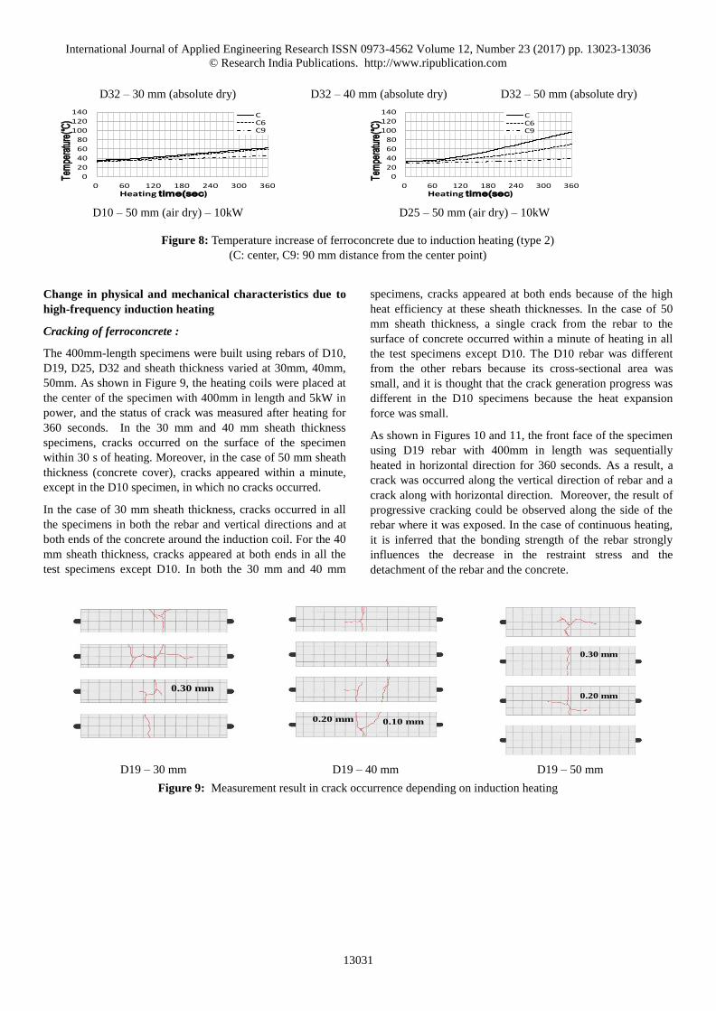
Cracking of ferroconcrete :
The 400mm-length specimens were built using rebars of D10,
D19, D25, D32 and sheath thickness varied at 30mm, 40mm,
50mm. As shown in Figure 9, the heating coils were placed at
the center of the specimen with 400mm in length and 5kW in
power, and the status of crack was measured after heating for
360 seconds. In the 30 mm and 40 mm sheath thickness
specimens, cracks occurred on the surface of the specimen
within 30 s of heating. Moreover, in the case of 50 mm sheath
thickness (concrete cover), cracks appeared within a minute,
except in the D10 specimen, in which no cracks occurred.
In the case of 30 mm sheath thickness, cracks occurred in all
the specimens in both the rebar and vertical directions and at
both ends of the concrete around the induction coil. For the 40
mm sheath thickness, cracks appeared at both ends in all the
test specimens except D10. In both the 30 mm and 40 mm
specimens, cracks appeared at both ends because of the high
heat efficiency at these sheath thicknesses. In the case of 50
mm sheath thickness, a single crack from the rebar to the
surface of concrete occurred within a minute of heating in all
the test specimens except D10. The D10 rebar was different
from the other rebars because its cross-sectional area was
small, and it is thought that the crack generation progress was
different in the D10 specimens because the heat expansion
force was small.
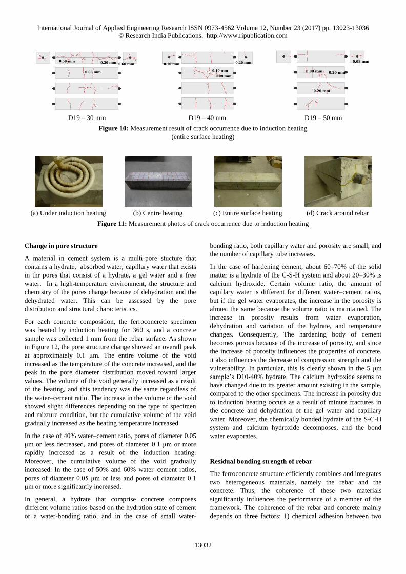
As shown in Figures 10 and 11, the front face of the specimen
using D19 rebar with 400mm in length was sequentially
heated in horizontal direction for 360 seconds. As a result, a
crack was occurred along the vertical direction of rebar and a
crack along with horizontal direction. Moreover, the result of
progressive cracking could be observed along the side of the
rebar where it was exposed. In the case of continuous heating,
it is inferred that the bonding strength of the rebar strongly
influences the decrease in the restraint stress and the
detachment of the rebar and the concrete.
D19 – 30 mm D19 – 40 mm D19 – 50 mm
Figure 9: Measurement result in crack occurrence depending on induction heating
0
20
40
60
80
100
120
140
0 60 120 180 240 300 360
Tem
pera
ture
(℃)
Heating time(sec)
CC6C9
0
20
40
60
80
100
120
140
0 60 120 180 240 300 360
Tem
pera
ture
(℃)
Heating time(sec)
CC6C9
0.30 mm
0.10 mm0.20 mm
0.30 mm
0.20 mm
International Journal of Applied Engineering Research ISSN 0973-4562 Volume 12, Number 23 (2017) pp. 13023-13036
© Research India Publications. http://www.ripublication.com
13032
D19 – 30 mm D19 – 40 mm D19 – 50 mm
Figure 10: Measurement result of crack occurrence due to induction heating
(entire surface heating)
(a) Under induction heating (b) Centre heating (c) Entire surface heating (d) Crack around rebar
Figure 11: Measurement photos of crack occurrence due to induction heating
Change in pore structure
A material in cement system is a multi-pore stucture that
contains a hydrate, absorbed water, capillary water that exists
in thr pores that consist of a hydrate, a gel water and a free
water. In a high-temperature environment, the structure and
chemistry of the pores change because of dehydration and the
dehydrated water. This can be assessed by the pore
distribution and structural characteristics.
For each concrete composition, the ferroconcrete specimen
was heated by induction heating for 360 s, and a concrete
sample was collected 1 mm from the rebar surface. As shown
in Figure 12, the pore structure change showed an overall peak
at approximately 0.1 μm. The entire volume of the void
increased as the temperature of the concrete increased, and the
peak in the pore diameter distribution moved toward larger
values. The volume of the void generally increased as a result
of the heating, and this tendency was the same regardless of
the water–cement ratio. The increase in the volume of the void
showed slight differences depending on the type of specimen
and mixture condition, but the cumulative volume of the void
gradually increased as the heating temperature increased.
In the case of 40% water–cement ratio, pores of diameter 0.05
μm or less decreased, and pores of diameter 0.1 μm or more
rapidly increased as a result of the induction heating.
Moreover, the cumulative volume of the void gradually
increased. In the case of 50% and 60% water–cement ratios,
pores of diameter 0.05 μm or less and pores of diameter 0.1
μm or more significantly increased.
In general, a hydrate that comprise concrete composes
different volume ratios based on the hydration state of cement
or a water-bonding ratio, and in the case of small water-
bonding ratio, both capillary water and porosity are small, and
the number of capillary tube increases.
In the case of hardening cement, about 60–70% of the solid
matter is a hydrate of the C-S-H system and about 20–30% is
calcium hydroxide. Certain volume ratio, the amount of
capillary water is different for different water–cement ratios,
but if the gel water evaporates, the increase in the porosity is
almost the same because the volume ratio is maintained. The
increase in porosity results from water evaporation,
dehydration and variation of the hydrate, and temperature
changes. Consequently, The hardening body of cement
becomes porous because of the increase of porosity, and since
the increase of porosity influences the properties of concrete,
it also influences the decrease of compression strength and the
vulnerability. In particular, this is clearly shown in the 5 μm
sample’s D10-40% hydrate. The calcium hydroxide seems to
have changed due to its greater amount existing in the sample,
compared to the other specimens. The increase in porosity due
to induction heating occurs as a result of minute fractures in
the concrete and dehydration of the gel water and capillary
water. Moreover, the chemically bonded hydrate of the S-C-H
system and calcium hydroxide decomposes, and the bond
water evaporates.
Residual bonding strength of rebar
The ferroconcrete structure efficiently combines and integrates
two heterogeneous materials, namely the rebar and the
concrete. Thus, the coherence of these two materials
significantly influences the performance of a member of the
framework. The coherence of the rebar and concrete mainly
depends on three factors: 1) chemical adhesion between two
0.50 mm
0.08 mm
0.20 mm 0.60 mm
0.10 mm
0.08 mm
0.10 mm 0.20 mm
0.20 mm
0.20 mm
0.08 mm
0.08 mm

International Journal of Applied Engineering Research ISSN 0973-4562 Volume 12, Number 23 (2017) pp. 13023-13036
© Research India Publications. http://www.ripublication.com
13033
materials 2) friction 3) internal mechanical reaction among
rebar, concrete that surrounds rebar, and rebar rib. At low-
stress conditions, the tensile stress of the rebar, as shown in
Figure 13(a), is transferred to the concrete, and this force acts
as a slope compression force on the concrete. Moreover, as
shown in Figure 13(b), the radial compressive force maintains
a balance with the tensile stress that is generated at the
concrete around the rebar, and the magnitude of the force that
is transferred from the rebar to the surrounding concrete is
determined by occurrence of cracks in the concrete sheath and
the destruction of the tension ring that comprises the tensile
force [12].
Figure 12: Pore structure change of single ferroconcrete due
to induction heating
A residual adhesive strength test according to ASTM C 234
that targets the deformed bar was conducted [13]. For the D19
rebar, a specimen that was not heated was compared with a
specimen that was subjected to induction heating at the centre
only and another specimen whose entire surface was subjected
to induction heating in the rebar direction. Then, a calculation
was performed in order to evaluate the restraint stress
quantitatively with respect to the change in sheath thickness.
As shown in Figure 14, the compressed force 𝐶 , given by
Equation 2, acts on the rebar with diameter 𝑑 and bond length
𝑙 and is transferred to the concrete by the compressed stress of
the rebar. The unit mean bond stress 𝜏b acts on the surface
area 𝜋𝑑𝑙 of the rebar.
𝐶 = 𝜋𝑑𝑙𝜏b (2)
where
𝐶 = compressed force acting on rebar
𝑑 = diameter of rebar
𝑙 = length of specimen
𝜏b = unit mean bond stress
Force transfer of ferroconcrete Compression force of radial form
Figure 13: Force transfer structure of rebar
Figure 14: Force transfer structure of rebar applied to experiment
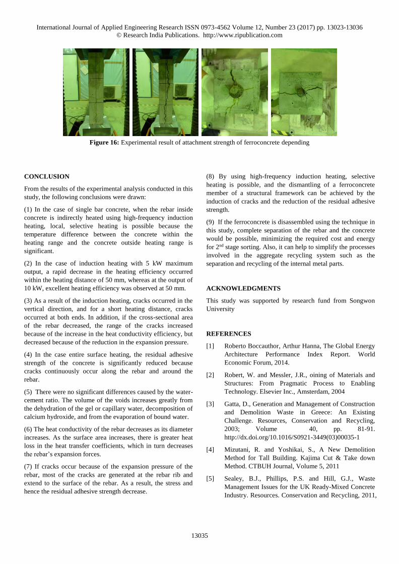
The chemical friction was disregarded in this experiment. As
shown in Figures 15 and 16, crack occurred due to the rebar
rib with the widest area according to the heat expansion
pressure generated by the induction heating. Therefore, it is
inferred that the bond stresses of the rebar rib and concrete,
and hence the bonding force, are reduced. Moreover when
comparing the non-heated specimen with the specimen that
was heated at the centre only, it was assumed that the same
load was applied on the bottom area of the rebar rib. As a
result, compared with the non-heated specimen, the specimen
that was heated in the centre only showed 58%, 8.3%, and
11.5% reduction in the stress at the bottom of the rebar rib and
0
0.005
0.01
0.015
0.02
0.001 0.01 0.1 1 10 100 1000
Incr
em
enta
l Intr
usi
on(
mL/g)
Pore size Diameter(μm)
D10-40% D10-40%H
D10-50% D10-50%H
D10-60% D10-60%H
L
P
ld
T=Abfs
ld
T=Abfs C

International Journal of Applied Engineering Research ISSN 0973-4562 Volume 12, Number 23 (2017) pp. 13023-13036
© Research India Publications. http://www.ripublication.com
13034
58%, 8.9%, and 12% reduction in the concrete stress for the
sheath thickness of 30 mm, 40 mm, and 50 mm, respectively.
Furthermore, the specimen whose entire surface was heated
along with rebar direction showed 61%, 29%, and 11.5%
reduction in the stress at the bottom of the rebar rib and 63%,
27.8%, and 12% reduction in the concrete stress for the sheath
thicknesses of 30 mm, 40 mm, 50 mm, respectively.
In the case of 30 mm sheath thickness, which has high heating
efficiency, more than 60% reduction in bonding strength was
observed. In the case of high heating efficiency, the overall
temperature of rebar was increased according to thermal
conductivity and it was confirmed that there was no significant
difference with the specimen whose entire surface was heated.
However, at low heating efficiency, there was more than a
20% difference between the partial heating and entire surface
heating cases. It is thought that the range of rebar expansion
pressure according to thermal conductivity is reduced because
the heating efficiency is reduced according to the distance. In
the case that a crack that occurred at the rebar rib extended to
the concrete surface, it was confirmed that the reduction in
concrete the stress was in direct proportion to the stress
reduction for which the rib was responsible.
In the specimens using the D25 rebar, the bonding strength
was reduced by 27.3%, 23.2%, and 17.4% at the sheath
thicknesses of 30 mm, 40 mm and 50 mm, respectively. Even
though the stress in the rib and the residual adhesive strength
of the concrete were reduced proportionally, it was confirmed
that the reduction in the residual adhesive strength of the rib
was slightly higher. In the case of the D32specimen, its
adhesive strength decreased by 15.4%, 17%, 17% in the order
of 30mm, 40mm and 50mm, respectively. If the cross section
area of attachment is wide and the heating efficiency is
reduced, the reduction rate of adhesive strength was also
decreased according to induction heating.
There were no significant differences between the reduction in
the stress of the rib and the reduction in the residual adhesive
strength of the concrete. In the specimens using the D10 rebar,
the results were slightly different because of the changes in
stress distribution due to the influence of rebar buckling in the
experiment. In addition, there were no significant differences
in the reduction of the bonding strength. In the case of partial
induction heating, the thermal conductivity ratio is decreased
as the diameter of rebar increases and it was confirmed that
the size and range of the heat expansion force of rebar rib
were decreased together as the heat loss of heat transfer
coefficient was increased in proportion to the area.
If cracks occur because of the expansion force of the rebar, it
is thought that most of cracks generated at the rebar rib are
transferred to the surface of the concrete, and thus the stress
and the bonding strength decrease. Moreover, the heat
generated at the surface of the rebar rib makes the concrete at
the bottom of the rebar rib and the concrete between the rib
and rebar vulnerable.
D19 D10
D25 D32
Figure 15: Experimental result of attachment strength of ferroconcrete depending on induction heating
(D00-000:D rebar diameter-heat distance mm-heating-all heating)
0.0
1.0
2.0
3.0
4.0
5.0
6.0
7.0
8.0
9.0
D19 - 30. 40. 50 D19 - 30h. 40h. 50h D19 - 30. 40. 50ah
Bon
d s
tren
gth
(M
Pa)
0.0
1.0
2.0
3.0
4.0
5.0
6.0
7.0
8.0
9.0
D10 - 30 D10 - 40 D10 - 30hD10 - 40hD10 - 50h
Bo
nd
str
eng
th (
MP
a)
0.0
1.0
2.0
3.0
4.0
5.0
6.0
7.0
8.0
9.0
D25 - 30 D25 - 40 D25 - 50 D25 - 30h D25 - 40h D25 - 50h
Bo
nd
str
eng
th (
MP
a)
0.0
1.0
2.0
3.0
4.0
5.0
6.0
7.0
8.0
9.0
D32 - 30 D32 - 40 D32 - 50 D32 - 30h D32 - 40h D32 - 50h
Bon
d s
tren
gth
(M
Pa)
International Journal of Applied Engineering Research ISSN 0973-4562 Volume 12, Number 23 (2017) pp. 13023-13036
© Research India Publications. http://www.ripublication.com
13035
Figure 16: Experimental result of attachment strength of ferroconcrete depending
CONCLUSION
From the results of the experimental analysis conducted in this
study, the following conclusions were drawn:
(1) In the case of single bar concrete, when the rebar inside
concrete is indirectly heated using high-frequency induction
heating, local, selective heating is possible because the
temperature difference between the concrete within the
heating range and the concrete outside heating range is
significant.
(2) In the case of induction heating with 5 kW maximum
output, a rapid decrease in the heating efficiency occurred
within the heating distance of 50 mm, whereas at the output of
10 kW, excellent heating efficiency was observed at 50 mm.
(3) As a result of the induction heating, cracks occurred in the
vertical direction, and for a short heating distance, cracks
occurred at both ends. In addition, if the cross-sectional area
of the rebar decreased, the range of the cracks increased
because of the increase in the heat conductivity efficiency, but
decreased because of the reduction in the expansion pressure.
(4) In the case entire surface heating, the residual adhesive
strength of the concrete is significantly reduced because
cracks continuously occur along the rebar and around the
rebar.
(5) There were no significant differences caused by the water-
cement ratio. The volume of the voids increases greatly from
the dehydration of the gel or capillary water, decomposition of
calcium hydroxide, and from the evaporation of bound water.
(6) The heat conductivity of the rebar decreases as its diameter
increases. As the surface area increases, there is greater heat
loss in the heat transfer coefficients, which in turn decreases
the rebar’s expansion forces.
(7) If cracks occur because of the expansion pressure of the
rebar, most of the cracks are generated at the rebar rib and
extend to the surface of the rebar. As a result, the stress and
hence the residual adhesive strength decrease.
(8) By using high-frequency induction heating, selective
heating is possible, and the dismantling of a ferroconcrete
member of a structural framework can be achieved by the
induction of cracks and the reduction of the residual adhesive
strength.
(9) If the ferroconcrete is disassembled using the technique in
this study, complete separation of the rebar and the concrete
would be possible, minimizing the required cost and energy
for 2nd stage sorting. Also, it can help to simplify the processes
involved in the aggregate recycling system such as the
separation and recycling of the internal metal parts.
ACKNOWLEDGMENTS
This study was supported by research fund from Songwon
University
REFERENCES
[1] Roberto Boccauthor, Arthur Hanna, The Global Energy
Architecture Performance Index Report. World
Economic Forum, 2014.
[2] Robert, W. and Messler, J.R., oining of Materials and
Structures: From Pragmatic Process to Enabling
Technology. Elsevier Inc., Amsterdam, 2004
[3] Gatta, D., Generation and Management of Construction
and Demolition Waste in Greece: An Existing
Challenge. Resources, Conservation and Recycling,
2003; Volume 40, pp. 81-91.
http://dx.doi.org/10.1016/S0921-3449(03)00035-1
[4] Mizutani, R. and Yoshikai, S., A New Demolition
Method for Tall Building. Kajima Cut & Take down
Method. CTBUH Journal, Volume 5, 2011
[5] Sealey, B.J., Phillips, P.S. and Hill, G.J., Waste
Management Issues for the UK Ready-Mixed Concrete
Industry. Resources. Conservation and Recycling, 2011,

International Journal of Applied Engineering Research ISSN 0973-4562 Volume 12, Number 23 (2017) pp. 13023-13036
© Research India Publications. http://www.ripublication.com
13036
Volume 32, pp. 321-324.
http://dx.doi.org/10.1016/S0921-3449(01)00069-6
[6] Uttam, K. and Balfors, B., 9-Green Public Procurement
(GPP) of Construction and Building Materials. Eco-
Efficient Construction and Building Materials, Life
Cycle Assessment (LCA), Eco-
[7] Labelling and Case Studies, 2014; pp. 166-195.
http://dx.doi.org/10.1533/9780857097729.1.166
[8] Sthiannopkao, S. and Wong, M.H., Handling E-Waste
in Developed and Developing Countries: Initiatives,
Practices, and Consequences. Science of The Total
Environment, 2013; Volume 463-
[9] 464, pp. 1147-1153.
http://dx.doi.org/10.1016/j.scitotenv.2012.06.088
[10] Myungkwan Lim, Development of Eco-Friendly
Deconstruction Technologies for Recycling
Construction Waste, Journal of Environmental
Protection, 2014; Volume 5, No.7, pp. 647-661
http://dx.doi.org/10.4236/jep.2014.57066
[11] Schneider, U., Properties of Materials at High
Temperatures-Concrete,2nd edn, RILEM Report,
Gesamthochschule Kassel, Germany, 1986
[12] Eurocode 2 : Design of concrete structures-Part 1-
2:General rules-Structural fire design, BSI, 2004, pp.
26~29
[13] T. Z. Harmathy, Fire Safety Design and Concrete,
Longman Scientific & Technical, 1993
[14] Sun-Jin Han, Degradation of flexural strength in
reinforced concrete members caused by steel corrosion,
2014; Volume. 54, pp. 572–583
[15] ASTM C 234, Standard Test Method for Comparing
Concrete on the basis of the bond Developed with
Reinforced Steel, ASTM. 1991