Embed Size (px)
Citation preview

EPCOS AG 2017. Reproduction, publication and dissemination of this publication, enclosures hereto and theinformation contained therein without EPCOS’ prior express consent is prohibited.
EPCOS AG is a TDK Group Company.
Ferrites and accessories
RM 8, RM 8 LPCore and accessories
Series/Type: B65811, B65812
Date: May 2017
The following products presented in this data sheet are being withdrawn.
Ordering Code Substitute Product Date of Withdrawal Deadline LastOrders
Last Shipments
B65812A5000X000 2018-06-08 2018-09-14 2018-12-14
For further information please contact your nearest EPCOS sales office, which will also support you in selecting a suitable substitute. Theaddresses of our worldwide sales network are presented at www.epcos.com/sales.

2 5/17Please read Cautions and warnings and Important notes at the end of this document.
Example of an assembly set
Individual parts Part no. Page
Adjusting screw B65812 9
Core B65811 3
Clamps B65812 8
Insulating washer 1 B65812 8
Coil former B65812 5
Core B65811 3
Threaded sleeve (glued-in)
Insulating washer 2 B65812 8
Also available: Coil former forSMPS transformers B65812 6Coil former forpower applications B65812 7
RM 8 low-profile:Core B65811P 10Clamp B65812 11Insulating washers 1 + 2 B65812 11
Core and accessoriesRM 8
3 5/17Please read Cautions and warnings and Important notes at the end of this document.
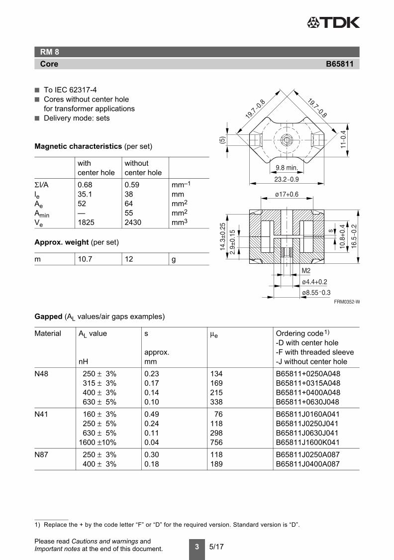
■ To IEC 62317-4■ Cores without center hole
for transformer applications■ Delivery mode: sets
Magnetic characteristics (per set)
Approx. weight (per set)
Gapped (AL values/air gaps examples)
withcenter hole
withoutcenter hole
Σ l/AleAeAminVe
0.6835.152—1825
0.593864552430
mm–1
mmmm2
mm2
mm3
m 10.7 12 g
Material AL value
nH
s
approx.mm
μe Ordering code1)
-D with center hole-F with threaded sleeve-J without center hole
N48 250 ± 3% 0.23 134 B65811+0250A048315 ± 3% 0.17 169 B65811+0315A048400 ± 3% 0.14 215 B65811+0400A048630 ± 5% 0.10 338 B65811+0630J048
N41 160 ± 3% 0.49 76 B65811J0160A041250 ± 5% 0.24 118 B65811J0250J041630 ± 5% 0.11 298 B65811J0630J041
1600 ±10% 0.04 756 B65811J1600K041N87 250 ± 3% 0.30 118 B65811J0250A087
400 ± 3% 0.18 189 B65811J0400A087
1) Replace the + by the code letter “F” or “D” for the required version. Standard version is “D”.
B65811CoreRM 8

4 5/17Please read Cautions and warnings and Important notes at the end of this document.
Ungapped
Other AL values/air gaps and materials available on request ─ see Processing remarks on page 12.
Material AL value
nH
μe PV
W/set
Ordering code-D with center hole-J without center hole
N48 2900 +30/–20% 1550 B65811D0000R048N30 5700 +30/–20% 2690 B65811J0000R030T38 12500 +40/–30% 5910 B65811J0000Y038N49 2200 +30/–20% 1040 < 0.37 ( 50 mT, 500 kHz, 100 °C) B65811J0000R049N87 3300 +30/–20% 1560 < 1.20 (200 mT, 100 kHz, 100 °C) B65811J0000R087N97 3300 +30/–20% 1560 < 1.00 (200 mT, 100 kHz, 100 °C) B65811J0000R097N41 4100 +30/–20% 1940 < 0.37 (200 mT, 25 kHz, 100 °C) B65811J0000R041N95 4100 +30/–20% 1940 < 1.10 (200 mT, 100 kHz, 100 °C) B65811J0000R095
B65811CoreRM 8
5 5/17Please read Cautions and warnings and Important notes at the end of this document.
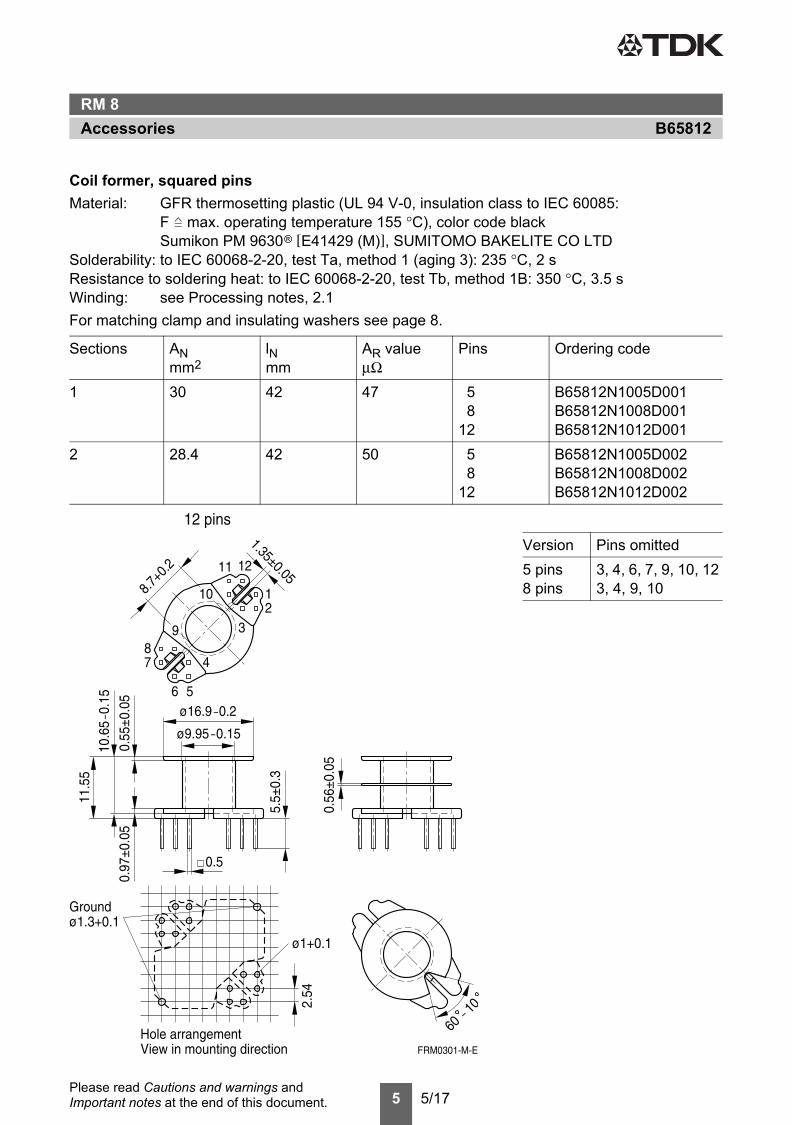
Coil former, squared pinsMaterial: GFR thermosetting plastic (UL 94 V-0, insulation class to IEC 60085:
F max. operating temperature 155 °C), color code blackSumikon PM 9630® [E41429 (M)], SUMITOMO BAKELITE CO LTD
Solderability: to IEC 60068-2-20, test Ta, method 1 (aging 3): 235 °C, 2 sResistance to soldering heat: to IEC 60068-2-20, test Tb, method 1B: 350 °C, 3.5 sWinding: see Processing notes, 2.1For matching clamp and insulating washers see page 8.
Sections ANmm2
lNmm
AR valueμΩ
Pins Ordering code
1 30 42 47 5 B65812N1005D0018 B65812N1008D001
12 B65812N1012D0012 28.4 42 50 5 B65812N1005D002
8 B65812N1008D00212 B65812N1012D002
Version Pins omitted5 pins8 pins
3, 4, 6, 7, 9, 10, 123, 4, 9, 10
B65812AccessoriesRM 8

6 5/17Please read Cautions and warnings and Important notes at the end of this document.
Coil former for SMPS transformers with line isolationThe creepage distances and clearances are designed such that the coil former is suitable for usein SMPS transformers with line isolation.■ Closed center flange with external wire guide■ Optimized for use with automatic winding machinesMaterial: GFR thermosetting plastic (UL 94 V-0, insulation class to IEC 60085:
F max. operating temperature 155 °C), color code blackSumikon PM 9630® [E41429 (M)], SUMITOMO BAKELITE CO LTD
Solderability: to IEC 60068-2-20, test Ta, method 1 (aging 3): 235 °C, 2 sResistance to soldering heat: to IEC 60068-2-20, test Tb, method 1B: 350 °C, 3.5 sWinding: see Processing notes, 2.1
Sections ANmm2
lNmm
AR valueμΩ
Pins Ordering code
2 28.4 42 50 8 B65812N1108D002
B65812AccessoriesRM 8

7 5/17Please read Cautions and warnings and Important notes at the end of this document.
Coil former for power applicationsOptimized for automatic windingMaterial: GFR polyterephthalate (UL 94 V-0, insulation class to IEC 60085:
F max. operating temperature 155 °C), color code blackValox 420-SE0 [E45329 (M)] SABIC INNOVATIVE PLASTICS B V
Solderability: to IEC 60068-2-20, test Ta, method 1 (aging 3): 235 °C, 2 sResistance to soldering heat: to IEC 60068-2-20, test Tb, method 1B: 350 °C, 3.5 sWinding: see Processing notes, 2.1For matching clamp and insulating washer 1 see page 8.
Sections ANmm2
lNmm
AR valueμΩ
Pins Ordering code
1 30 42 47 12 B65812C1512T001
Hole arrangementView in mounting direction(Note half pitch!)
B65812AccessoriesRM 8
8 5/17Please read Cautions and warnings and Important notes at the end of this document.
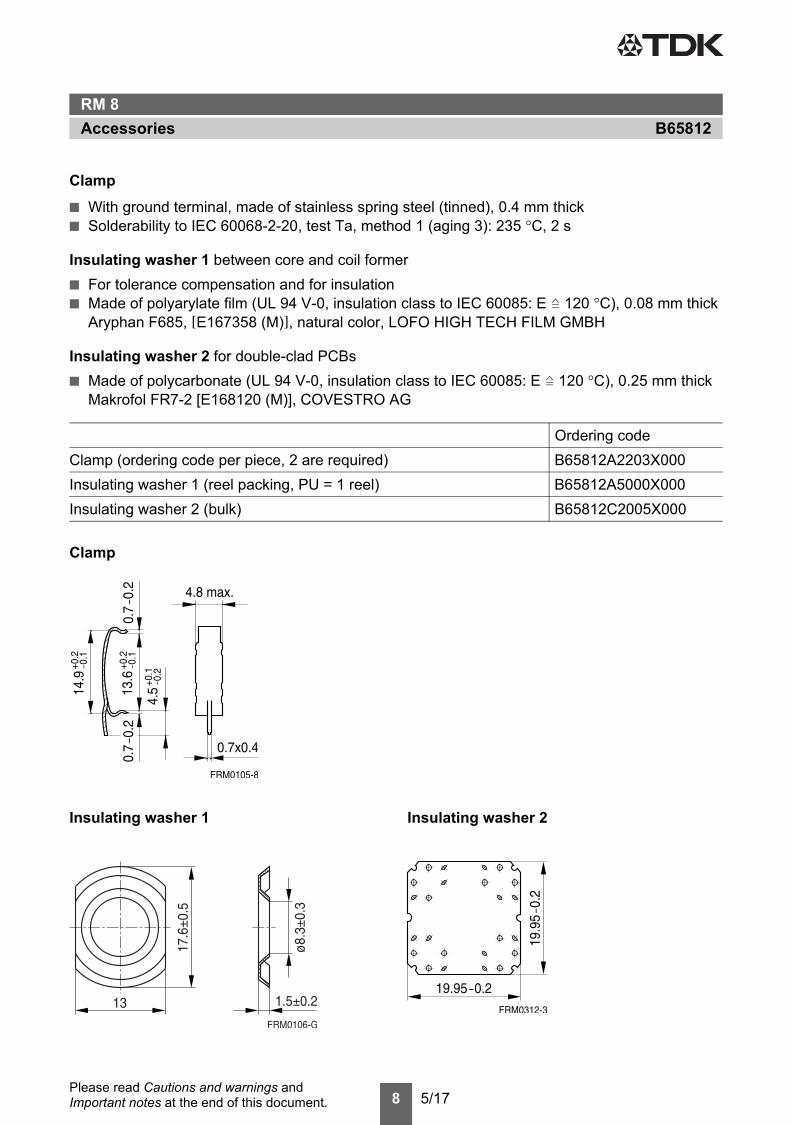
Clamp■ With ground terminal, made of stainless spring steel (tinned), 0.4 mm thick■ Solderability to IEC 60068-2-20, test Ta, method 1 (aging 3): 235 °C, 2 s
Insulating washer 1 between core and coil former■ For tolerance compensation and for insulation■ Made of polyarylate film (UL 94 V-0, insulation class to IEC 60085: E 120 °C), 0.08 mm thick
Aryphan F685, [E167358 (M)], natural color, LOFO HIGH TECH FILM GMBH
Insulating washer 2 for double-clad PCBs■ Made of polycarbonate (UL 94 V-0, insulation class to IEC 60085: E 120 °C), 0.25 mm thick
Makrofol FR7-2 [E168120 (M)], COVESTRO AG
Clamp
Ordering codeClamp (ordering code per piece, 2 are required) B65812A2203X000Insulating washer 1 (reel packing, PU = 1 reel) B65812A5000X000Insulating washer 2 (bulk) B65812C2005X000
Insulating washer 1 Insulating washer 2
B65812AccessoriesRM 8
9 5/17Please read Cautions and warnings and Important notes at the end of this document.
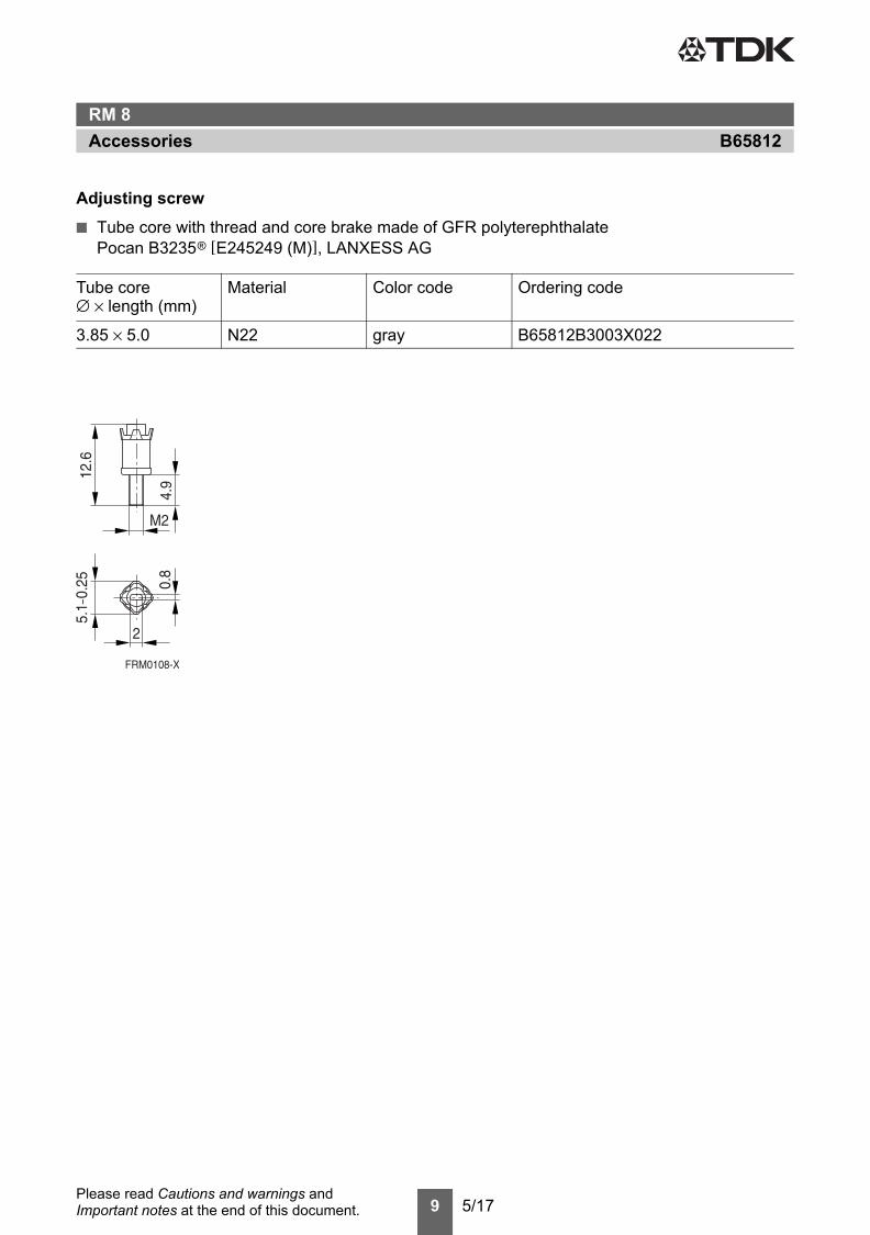
Adjusting screw■ Tube core with thread and core brake made of GFR polyterephthalate
Pocan B3235® [E245249 (M)], LANXESS AG
Tube core Material Color code Ordering code∅ × length (mm)
3.85 × 5.0 N22 gray B65812B3003X022
B65812AccessoriesRM 8

10 5/17Please read Cautions and warnings and Important notes at the end of this document.
■ To IEC 62317-4■ For compact transformers■ Without center hole■ Delivery mode: sets
Magnetic characteristics (per set)Σ l/A = 0.44 mm–1
le = 28.7 mmAe = 64.9 mm2
Amin = 55.4 mm2
Ve = 1860 mm3
Approx. weight 9.2 g/set
Ungapped
Other AL values/air gaps and materials available on request ─ see Processing remarks on page 12.
Material AL value
nH
μe PV
W/set
Ordering code
N49 2900 +30/–20% 1020 < 0.33 ( 50 mT, 500 kHz, 100 °C) B65811P0000R049N92 3100 +30/–20% 1090 < 1.10 (200 mT, 100 kHz, 100 °C) B65811P0000R092N87 4100 +30/–20% 1440 < 0.92 (200 mT, 100 kHz, 100 °C) B65811P0000R087
B65811PCoreRM 8 »Low Profile«

11 5/17Please read Cautions and warnings and Important notes at the end of this document.
Clamp■ With ground terminal, made of stainless spring steel (tinned), 0.4 mm thick■ Solderability to IEC 60068-2-20, test Ta, method 1 (aging 3): 235 °C, 2 s
Insulating washer 1 between core and coil former■ For tolerance compensation and for insulation■ Made of polyarylate film (UL 94 V-0, insulation class to IEC 60085: E 120 °C), 0.08 mm thick
Aryphan F685, [E167358 (M)], natural color, LOFO HIGH TECH FILM GMBH
Insulating washer 2 for double-clad PCBs■ Made of polycarbonate (UL 94 V-0, insulation class to IEC 60085: E 120 °C), 0.25 mm thick
Makrofol FR7-2 [E168120 (M)], COVESTRO AG
Clamp
Ordering codeClamp (ordering code per piece, 2 are required) B65812P2203X000Insulating washer 1 (reel packing, PU = 1 reel) B65812A5000X000Insulating washer 2 (bulk) B65812C2005X000
Insulating washer 1 Insulating washer 2
B65812AccessoriesRM 8 »Low Profile«

12 5/17Please read Cautions and warnings and Important notes at the end of this document.
Mechanical stress and mountingFerrite cores have to meet mechanical requirements during assembling and for a growing numberof applications. Since ferrites are ceramic materials one has to be aware of the special behaviorunder mechanical load.As valid for any ceramic material, ferrite cores are brittle and sensitive to any shock, fast tempera-ture changing or tensile load. Especially high cooling rates under ultrasonic cleaning and high staticor cyclic loads can cause cracks or failure of the ferrite cores.For detailed information see data book, chapter “General - Definitions, 8.1”.
Effects of core combination on AL value Stresses in the core affect not only the mechanical but also the magnetic properties. It is apparentthat the initial permeability is dependent on the stress state of the core. The higher the stresses arein the core, the lower is the value for the initial permeability. Thus the embedding medium shouldhave the greatest possible elasticity.For detailed information see data book, chapter “General - Definitions, 8.1”.
Heating upFerrites can run hot during operation at higher flux densities and higher frequencies.
NiZn-materials The magnetic properties of NiZn-materials can change irreversible in high magnetic fields.
Ferrite AccessoriesEPCOS ferrite accessories have been designed and evaluated only in combination with EPCOSferrite cores. EPCOS explicitly points out that EPCOS ferrite accessories or EPCOS ferrite coresmay not be compatible with those of other manufacturers. Any such combination requires prior te-sting by the customer and will be at the customer‘s own risk.EPCOS assumes no warranty or reliability for the combination of EPCOS ferrite accessories withcores and other accessories from any other manufacturer.
Processing remarksThe start of the winding process should be soft. Else the flanges may be destroyed.– Too strong winding forces may blast the flanges or squeeze the tube that the cores can not be
mounted any more.– Too long soldering time at high temperature (>300 °C) may effect coplanarity or pin arrange-
ment.– Not following the processing notes for soldering of the J-leg terminals may cause solderability
problems at the transformer because of pollution with Sn oxyde of the tin bath or burned insula-tion of the wire. For detailed information see chapter “Processing notes”, section 2.2.
– The dimensions of the hole arrangement have fixed values and should be understood asa recommendation for drilling the printed circuit board. For dimensioning the pins, the groupof holes can only be seen under certain conditions, as they fit into the given hole arrangement.To avoid problems when mounting the transformer, the manufacturing tolerances for positioning the customers’ drilling process must be considered by increasing the hole diameter.
Cautions and warningsFerrites and accessories
Cautions and warnings

13 5/17Please read Cautions and warnings and Important notes at the end of this document.
Ferrites and accessories
Display of ordering codes for EPCOS productsThe ordering code for one and the same product can be represented differently in data sheets, data books, other publications and the website of EPCOS, or in order-related documents such asshipping notes, order confirmations and product labels. The varying representations of the ordering codes are due to different processes employed and do not affect the specifications of the respective products. Detailed information can be found on the Internet under www.epcos.com/orderingcodes.
Cautions and warnings
14 5/17Please read Cautions and warnings and Important notes at the end of this document.
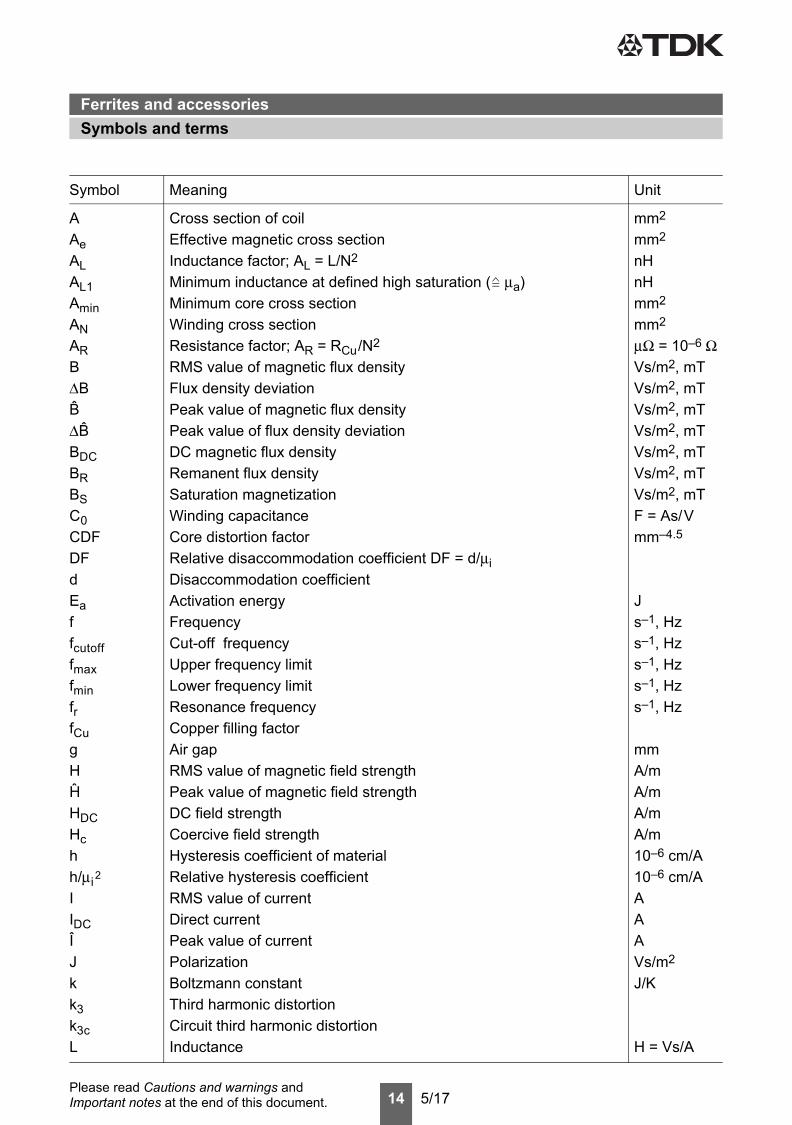
Symbol Meaning Unit
AAeALAL1AminANARBΔBB ΔB BDCBRBSC0CDFDFdEaffcutofffmaxfminfrfCugHH HDCHchh/μi 2
IIDCIJkk3k3cL
Cross section of coilEffective magnetic cross sectionInductance factor; AL = L/N2
Minimum inductance at defined high saturation ( μa)Minimum core cross sectionWinding cross sectionResistance factor; AR = RCu/N2
RMS value of magnetic flux densityFlux density deviationPeak value of magnetic flux densityPeak value of flux density deviationDC magnetic flux densityRemanent flux densitySaturation magnetizationWinding capacitanceCore distortion factorRelative disaccommodation coefficient DF = d/μiDisaccommodation coefficientActivation energyFrequencyCut-off frequencyUpper frequency limitLower frequency limitResonance frequencyCopper filling factorAir gapRMS value of magnetic field strengthPeak value of magnetic field strengthDC field strengthCoercive field strengthHysteresis coefficient of materialRelative hysteresis coefficientRMS value of currentDirect currentPeak value of currentPolarizationBoltzmann constantThird harmonic distortionCircuit third harmonic distortionInductance
mm2
mm2
nHnHmm2
mm2
μΩ = 10–6 ΩVs/m2, mTVs/m2, mTVs/m2, mTVs/m2, mTVs/m2, mTVs/m2, mTVs/m2, mTF = As/Vmm–4.5
Js–1, Hzs–1, Hzs–1, Hzs–1, Hzs–1, Hz
mmA/mA/mA/mA/m10–6 cm/A10–6 cm/AAAAVs/m2
J/K
H = Vs/A
Symbols and termsFerrites and accessories
Symbols and terms
15 5/17Please read Cautions and warnings and Important notes at the end of this document.
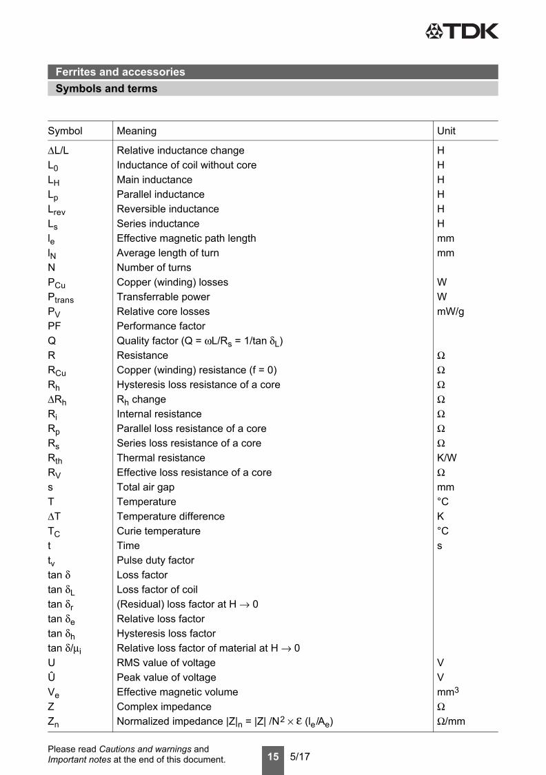
Symbol Meaning Unit
ΔL/LL0LHLpLrevLslelNNPCuPtransPVPFQRRCuRhΔRhRiRpRsRthRVsTΔTTCttvtan δtan δLtan δrtan δetan δhtan δ/μiUÛVeZZn
Relative inductance changeInductance of coil without coreMain inductanceParallel inductanceReversible inductanceSeries inductanceEffective magnetic path lengthAverage length of turnNumber of turnsCopper (winding) lossesTransferrable powerRelative core lossesPerformance factorQuality factor (Q = ωL/Rs = 1/tan δL)ResistanceCopper (winding) resistance (f = 0)Hysteresis loss resistance of a coreRh changeInternal resistanceParallel loss resistance of a coreSeries loss resistance of a coreThermal resistanceEffective loss resistance of a coreTotal air gapTemperatureTemperature differenceCurie temperatureTimePulse duty factorLoss factorLoss factor of coil(Residual) loss factor at H → 0Relative loss factorHysteresis loss factorRelative loss factor of material at H → 0RMS value of voltagePeak value of voltageEffective magnetic volumeComplex impedanceNormalized impedance |Z|n = |Z| /N2 × ε (le/Ae)
HHHHHHmmmm
WWmW/g
ΩΩΩΩΩΩΩK/WΩmm°CK°Cs
VVmm3
ΩΩ/mm
Symbols and termsFerrites and accessories

16 5/17Please read Cautions and warnings and Important notes at the end of this document.
All dimensions are given in mm.
Surface-mount device
Symbol Meaning Unit
ααFαeεrΦηηBηiλsμμ0μaμappμeμiμp'μp"μrμrevμs'μs"μtot
ρΣl/AτCuω
Temperature coefficient (TK)Relative temperature coefficient of materialTemperature coefficient of effective permeabilityRelative permittivityMagnetic fluxEfficiency of a transformerHysteresis material constantHysteresis core constantMagnetostriction at saturation magnetizationRelative complex permeabilityMagnetic field constantRelative amplitude permeabilityRelative apparent permeabilityRelative effective permeabilityRelative initial permeabilityRelative real (inductive) component of μ (for parallel components)Relative imaginary (loss) component of μ (for parallel components)Relative permeabilityRelative reversible permeabilityRelative real (inductive) component of μ (for series components)Relative imaginary (loss) component of μ (for series components)Relative total permeabilityderived from the static magnetization curveResistivityMagnetic form factorDC time constant τCu = L/RCu = AL/ARAngular frequency; ω = 2 Πf
1/K1/K1/K
Vs
mT-1
A–1H–1/2
Vs/Am
Ωm–1
mm–1
ss–1
Symbols and termsFerrites and accessories
17 5/17Please read Cautions and warnings and Important notes at the end of this document.
The following applies to all products named in this publication:
1. Some parts of this publication contain statements about the suitability of our products forcertain areas of application. These statements are based on our knowledge of typical require-ments that are often placed on our products in the areas of application concerned. We never-theless expressly point out that such statements cannot be regarded as binding statementsabout the suitability of our products for a particular customer application. As a rule, EP-COS is either unfamiliar with individual customer applications or less familiar with them than thecustomers themselves. For these reasons, it is always ultimately incumbent on the customer tocheck and decide whether an EPCOS product with the properties described in the product spec-ification is suitable for use in a particular customer application.
2. We also point out that in individual cases, a malfunction of electronic components or fail-ure before the end of their usual service life cannot be completely ruled out in the currentstate of the art, even if they are operated as specified. In customer applications requiring avery high level of operational safety and especially in customer applications in which the mal-function or failure of an electronic component could endanger human life or health (e.g. in acci-dent prevention or life-saving systems), it must therefore be ensured by means of suitable de-sign of the customer application or other action taken by the customer (e.g. installation of pro-tective circuitry or redundancy) that no injury or damage is sustained by third parties in the eventof malfunction or failure of an electronic component.
3. The warnings, cautions and product-specific notes must be observed.
4. In order to satisfy certain technical requirements, some of the products described in this pub-lication may contain substances subject to restrictions in certain jurisdictions (e.g. be-cause they are classed as hazardous). Useful information on this will be found in our MaterialData Sheets on the Internet (www.epcos.com/material). Should you have any more detailedquestions, please contact our sales offices.
5. We constantly strive to improve our products. Consequently, the products described in thispublication may change from time to time. The same is true of the corresponding productspecifications. Please check therefore to what extent product descriptions and specificationscontained in this publication are still applicable before or when you place an order.
We also reserve the right to discontinue production and delivery of products. Consequent-ly, we cannot guarantee that all products named in this publication will always be available. Theaforementioned does not apply in the case of individual agreements deviating from the foregoingfor customer-specific products.
6. Unless otherwise agreed in individual contracts, all orders are subject to the current versionof the “General Terms of Delivery for Products and Services in the Electrical Industry”published by the German Electrical and Electronics Industry Association (ZVEI).
7. The trade names EPCOS, CeraCharge, CeraDiode, CeraLink, CeraPad, CeraPlas, CSMP,CTVS, DeltaCap, DigiSiMic, ExoCore, FilterCap, FormFit, LeaXield, MiniBlue, MiniCell, MKD,MKK, MotorCap, PCC, PhaseCap, PhaseCube, PhaseMod, PhiCap, PowerHap, PQSine,PQvar, SIFERRIT, SIFI, SIKOREL, SilverCap, SIMDAD, SiMic, SIMID, SineFormer, SIOV,ThermoFuse, WindCap are trademarks registered or pending in Europe and in othercountries. Further information will be found on the Internet at www.epcos.com/trademarks.
Important notes


![Ferrites Brochure 46[1]](https://img.pdfslide.us/doc/110x75/5451c66baf795908308b4ac2/ferrites-brochure-461.jpg)