Embed Size (px)
Citation preview
. . . - . - . . . . . - . -. .. . ! ?. L . ....
+- 2 8 3 9
. . . protecting tbe environment .
Fernald 'Silo 3 Project
Site Preparation Package
February 25,2000
, I
. . . . . . . . . . . . . . . .
Rocky Mountain e 2 8 3 9 Remediation Services, L L C
*&!a pmlacdng#n r m h n m r n l
- RMRS ...
TABLE OF CONTENTS
1.0 INTRODUCTION .............. ~ .............................................................................................. 1
2.0 PURPOSE .......................................................................................................................... 1
3.0 DESCRIPTION OF TBE WORK ...................................................... : ............................. 1
4.0 INTERFACE WITH SITE UTILITIES .......................................................................... . 3
5.0 PRE-OPERATIONAL ENVIRONMENTAL CONTROL PLAN ................................. .4
6.0 LIST OF DRAWINGS ..................................................................................................... .4
7.0 LIST OF SPECIFICATIONS ........................................................................................... 5
S.0 PORTABLE STRUCTURES INFORMATION .............................................................. 5
Attachment A Attachment B Attachment C Attachment D Attachment E
Pre-Operational Environmental Control Plan Site Preparation Package Design Drawings Site Preparation Package Technical Specs RUBB Building Manufacturer’s Data Typical Portable Trailer Data
FebNery 25,2000 ii General Description of the Work
1 2 3 4 5 6 7 8 9
10 11 12 13 14 15 16 17 18 19 20
22 23 24 25 26 27 28 29 30 31 32 33 34 35 36 37 38 39 40 41 42 43
,\i .,:, .e,.*2 1
Rocky Mountain = 2 8 3 9 RMRS -4a
I _ - Remediation Services, L L C ... purrrung Um rmfmnm*nf
1.0 INTRODUCTION
Fluor Daniel Fernald (FDF) has contracted Rocky Mountain Remediation Services (RMRS) to design, construct, start-up, operate, maintain, shutdown, and dismantle the retrieval and treatment system for remediating the Silo 3 waste. The site preparation design package provides the design documents necessary to prepare the Silo 3 project site for the facilities and infrastructure required to perform the remediatioh :!?nrt in a safe and compliant manner.
2.0 PURPOSE
The purpose of the Site Preparation Package is to convey the requirements for site development and preparation for facilities associated with the Silo 3 Project. Concepts presented herein have been developed into the final design drawings, specifications, and calculations for this Site Preparation Package.
This document is not intended to restate the design basis or safety basis requirements for the site preparation activities, which have been presented in other documents, but rather to provide a description of the physical facilities and their impact on the existing site characteristics.
3.0 DESCRIPTION OF THE WORK
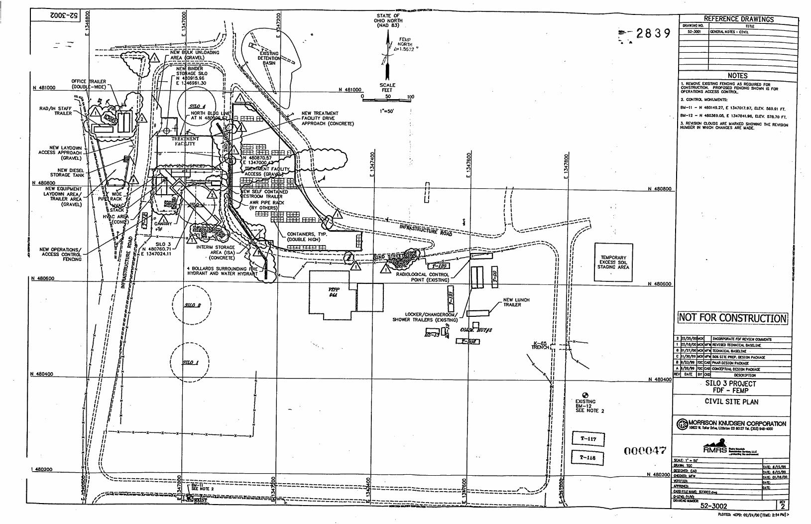
The facilities associated with the Silo 3 Project are generally depicted on drawing 52-3002, Site Plan (See Attachment B). Following is a brief description of these facilities: '
Site Preparation, Clearing and Fencing. The design has minimized the amount clearing required around the Silo 3 facilities. The areas to be cleared will be noticeably marked, and an excavatiodpenetration permit will be acquired prior to the start of clearing and removal of underground lines. Disturbed soil will be managed as radiologically contaminated until it is proven to be otherwise. Construction and operations access control will be provided by the use of high density polyethylene fencing material, orange for construction fencing and yellow for radiological boundaries, or metal fencing with appropriate signs. Construction waste is further discussed in the Waste Management Plan. Areas between facilities will be maintained as walks or driveways or reseeded. An existing, inactive, underground utilities duct bank in the vicinity of the Silos will be removed to make room for the building and gantq foundations.
New Treatment Facility. The treatment facility will house the conveyance, treatment, and packaging systems associated with the Envirobond treatment system. The facility wilt be a
2 <'. 0
February 25,2000 1 of5 Generd Descriplion of the Work
orOcc?rl)3
1 2 3 4 5 6 7 S 9
10 1 1 12 13 14 15 16 17 1s 19 20
22 23 24 25 26 27 28 29 30 31 32 33 34 35 36 37 3s 39 40 41 42 43
;:t\. :. 21 '..-.
Rocky Mountain = 2 8 3 9 Remediation Services. LLC ... pmCec#ngUm emlmnmml
steel fiamed structure with a tensioned PVC coated polyester fabric membrane exterior covering, as manufactured by RUBB Building Systems. Within the facility, a secondary fabric will be supported fiom the structure to provide containment for an Airborne Radioactivity Area (ARA) for both treatment and process re-work. Manufacturer's data on the RUBB structure is shown in Attachment D.
The facility foundation system (Attachment By Drawings 52-32 10, 52-32 1 1 and 52-32 12) will provide structural support for the building and equipment as well as provide containment of potential spills. The foundation system will be a shallow continuous footing with strip walls and required isolated equipment footings. Bounding each ARA is the interior f h i c , a containment curio, and a sump system. Liquids from any spills occurring in these areas will be collected in the sump and pumped into the process water tank for future process use. Any spills requiring wash down will be washed into the sump outside the ARA and then pumped by portable pump into containers, analyzed, and disposed or treated appropriately.
Treatment Facility Check Point. The check point facility and a restroom trailer will be located adjacent to the treatment facility. The check point facility will house the shift supervisor's office and the change room. Access to Silo 3 facilities will be controlled at this facility. This facility will be a temporary, portable trailer, delivered to site and anchored in place in accordance with site requirements. Typical manufacturer's drawings are shown in Attachment E. The restroom trailer will have a self-contained sewage tank that requires routine emptying. The trailer will be equipped with a domestic water supply.
Silo Gantq and Containment House. To access the silo for waste retrieval, a fixed gantq will be constructed over Silo 3 to support the retrieval manipulator. The silo gantry will be a structural steel box truss with an enclosed containment house for the retrieval system. Primary access to the containment house will be via a stair tower on the northwest support. A 4-ton hoist will be located on the southeast tower for lifting equipment and accessories.
The foundation for the gantry structure (Attachment By Drawings 52-3 1 10 and 52-3 1 1 1) will be a shallow mat footing with pedestals for connection to structural steel.
W A C Area (Attachment By Drawing 52-3400 and 52-3 113). The W A C Area will be located south of the treatment facility. This concrete slab will be constructed to allow placement and maintenance of W A C trains. An exhaust stack, supported by the retrieval pipe bridge, will be located on the northwest comer of the W A C slab.
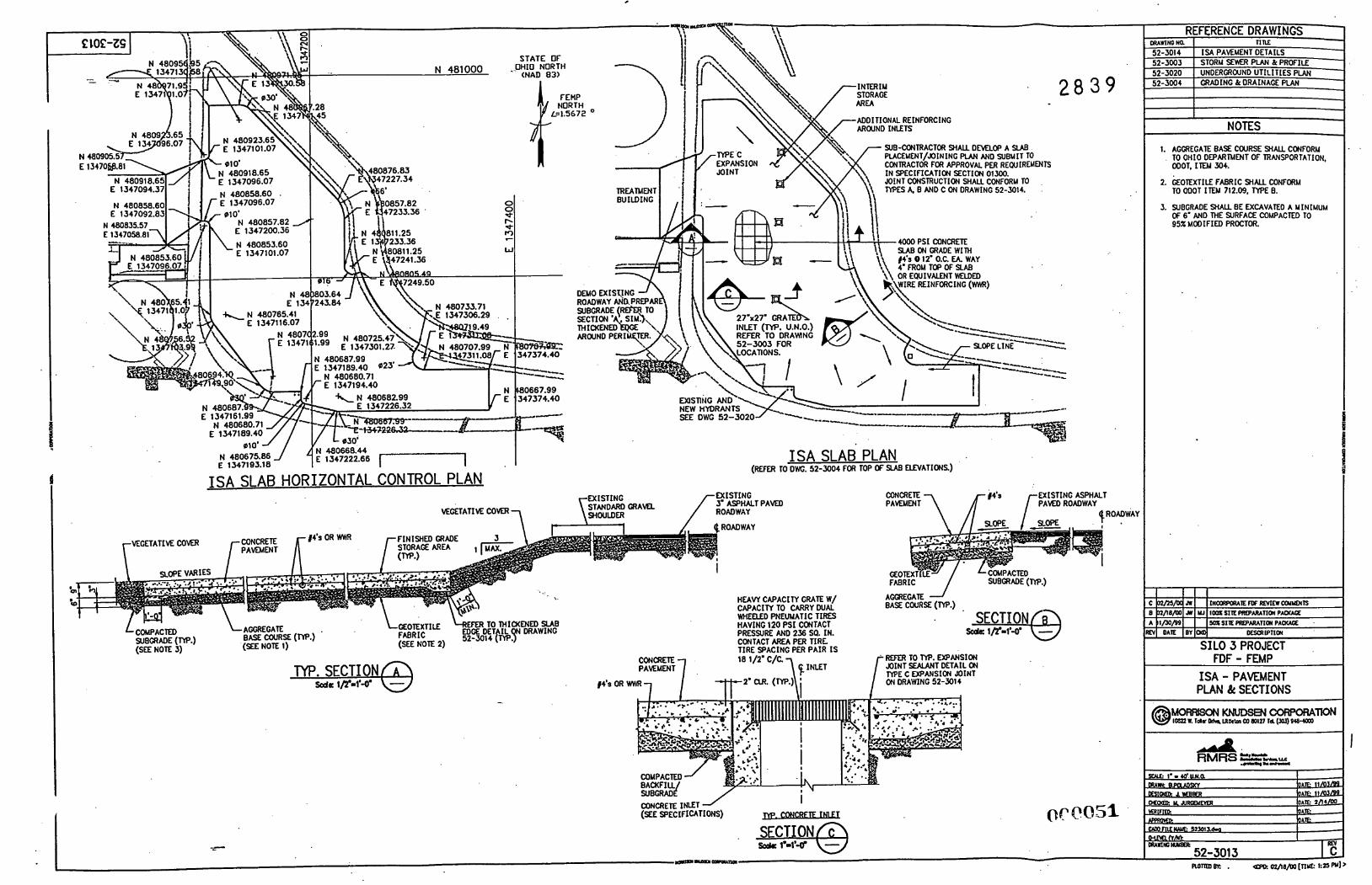
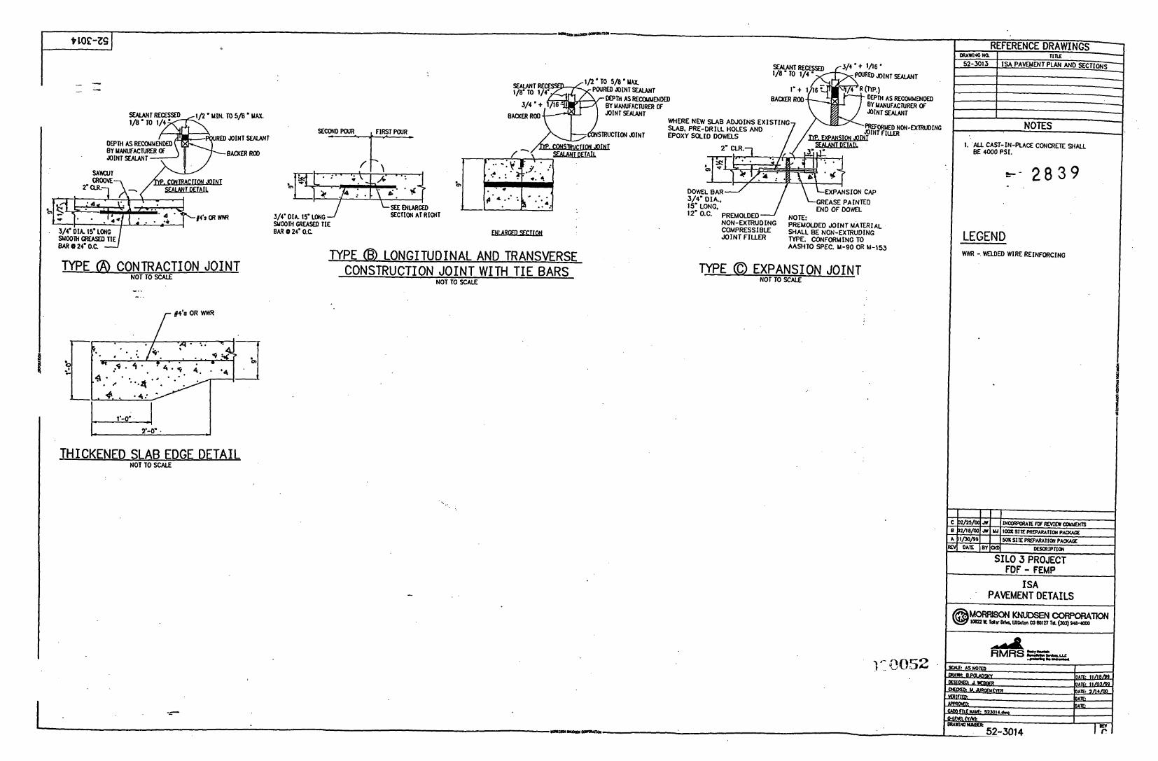
Interim Storage Area (Attachment By Drawings 52-3013 and 52-3014). The Interim Storage Area @SA) will be.located east of 2"d Street and west of the new infrastructure road. This area will be used to stage treated waste while it is analyzed for waste acceptance criteria and prior to turnover to Fluor Fernald. The ISA will be a concrete slab-on-grade, designed for a service life of 20 years.. The pad will include (approximately) 42,000 sq. fi. of slab area, and will be designed for a 52,000 pound capacity dual-wheeled pneumatic tire lift truck with 120
2of5 General Desclipkn of the Work February 25,2000
(34)P'CtOQ
. . .
Rocky Mountain 4 2 8 3 9 - RMRS -4a
Remediation Services, LLC . . . pmtuUng me ~ r n l r o m 8 n I
1 2 3 4 5 6 7 8 9
10 11 12 13 14 15 16 17 18 19 20
, ... $?l 22 23 24 25 26 27 28 29 30 31 32 33 34 35 36 37 38 39 40 41 42 13
psi tire inflation pressure.
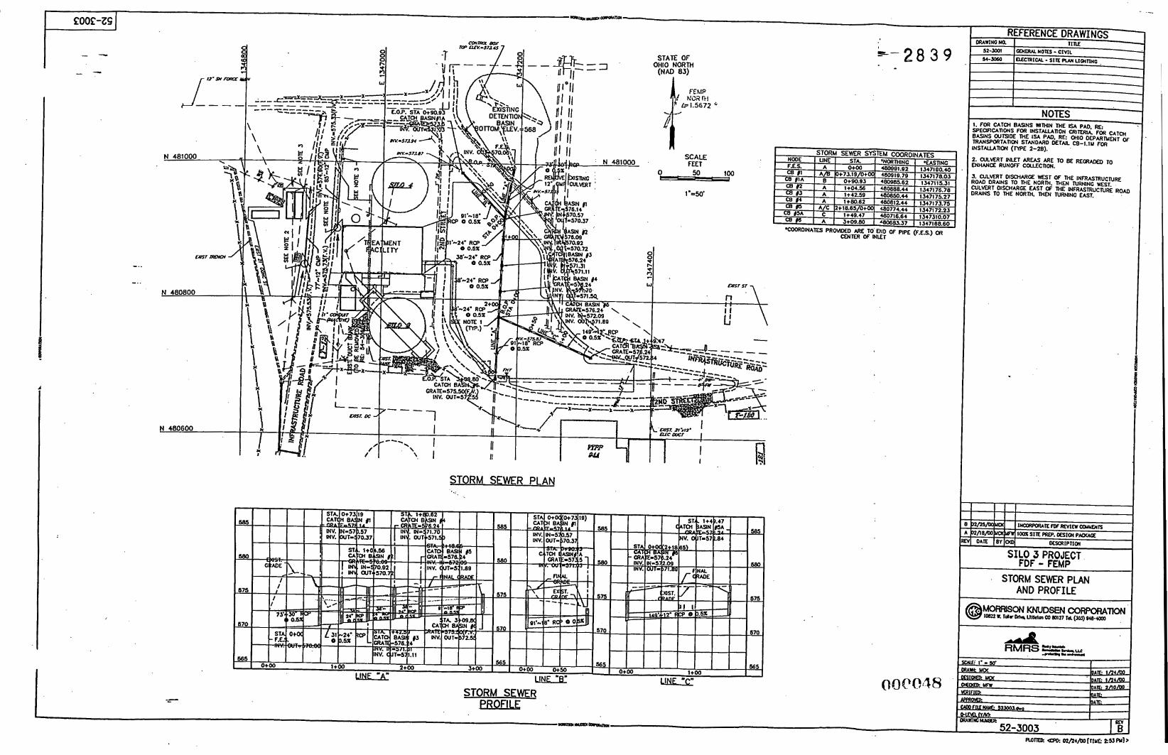
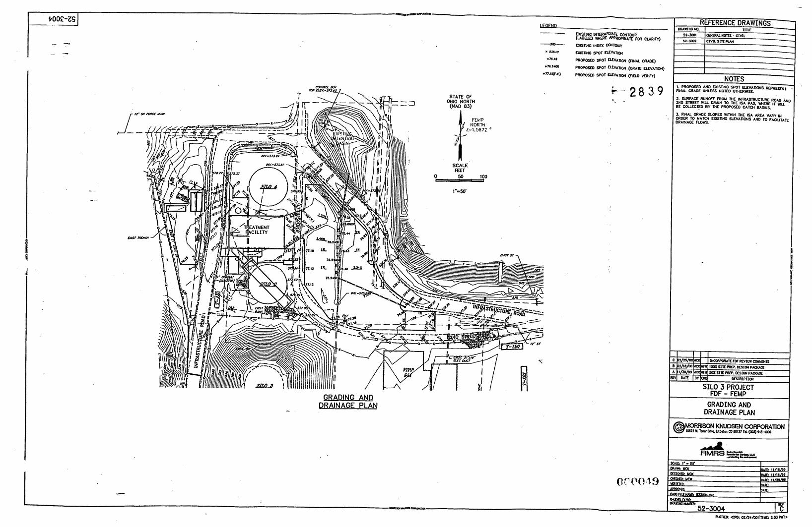
Although the slab area crosses into existing drainage basin D (Attachment B, Drawings 52- 3004 and 52-3016), storm water fiom the ISA slab will be collected within existing drainage basin C and discharged to the retention basin north of the inf?astructure road. No modifications to other storm water basins are expected.
The ISA will include a domestic water outlet (Attachment B, Drawing 52-3020) and lighting (Attachment B, Drawing 54-3060) to the requirements of OSHA 1926.56. Each new lighting pole will be equipped with 480V sodium lighting (or eqcQ and 120V outlets. The existing radon monitor T-28 will be relocated as shown on the drawings. Existing power poles in the area will be removed and overhead circuits rerouted as needed.
Equipment Laydown Area (Attachment B, Drawing 52-3004). The equipment laydown area will be located west of the silos, across the infrastructure road. This area will be graded, and with its gravel base, will be used for temporatry material storage for construction and operations. A diesel fuel storage tank with built-in double containment will be adjacent to the laydown area. Vehicles will access the tank by entering the laydown area (off the infrastructure road).
Project Support Area. The project support area will be adjacent to the laydown area. This area includes the office trailer and the racUIH trailer. The office and racUIH trailers will be temporary, portable trailers delivered to site and anchored in place in accordance with site requirements. Typical manufacturer’s drawings are shown in Attachment E.
Lunch Trailer. A lunch trailer will be located outside of the Controlled Area, south of the ’
existing change facilities. This facility will be a temporary, portable trailer delivered to site and anchored in place in accordance with site requirements. Typical manufacturer’s drawings are shown in Attachment E.
4.0 INTERFACE WITH SITE UTILITIES
The Silo 3 Project site work will tie-in to existing FEW site utilities as outlined below.
Electrical Power. Electrical power will be obtained from a new 1000 kVA transformer located west of Silo 4. Existing underground conduits extending from the transformer pad will be utilized to provide primary power feeds to facilities on either side of the fiastmcture road to avoid disturbing the newly constructed roadway. Lighting and power circuits for the new ISA will be provided overhead fiom existing transformer SE 8 17. The new lunch trailer will be fed from a 50 kVA transformer near existing pole WP 064.
February 25,2000 3 o f 5 General Descripfion of the Work
Ai& Rocky Mountain - RMRS Remedhtion Services. L t C
s- 2 8 3 9
1 2 3 4 5 6 7 8 9
10 1 1 12 13 14 15 16 17 18 19 20
. . 2 1 22 23 24 25 26 27 28 29 30 31 32 33 34 35 36 37 38 39 40 41 42
~ : q * . : : ~ > c ? i ~ . .
Communication and Alarm Systems. The fire alarm system will be interfaced via phone lines to the Fernald Central Alarm Center and Fire Department Dispatch Center. Existing voice alarm and evacuation systems will be interfaced from the control units in the Vitrification Pilot Plant (VTPP). This interface will be at an existkg junction box on pole WP 006 via an existing cable from the VTPP that is terminated in the junction box.
Phone lines. Phone lines will be provided to project facilities as required to support operations of the retrieval and treatment process. Phone lines for the fire alarm system and general use are available via a 25 pair phone cable at pole WP 006.
Domestic and Fire Water. Existing fire water and domestic water lines will be extended underground to the Silo 3 project facilities. Both water lines will be installed in a common trench while maintaining required separation. The fire water underground pipeline will extend to a point outside the treatment facility at the southeast comer. The domestic water underground pipeline will extend to the restroom trailer.
5.0 PRE-OPERATIONAL ENVIRONMENTAL CONTROL PLAN
Attachment A of this document includes the Pre-Operational Environmental Control Plan. This plan provides the waste management, dust control and erosion control requirements for site construction for the Silo 3 Project.
6.0 LIST OF DRAWINGS
Attachment B contains the following drawing, which depict the site preparation design for the Silo 3 Project:
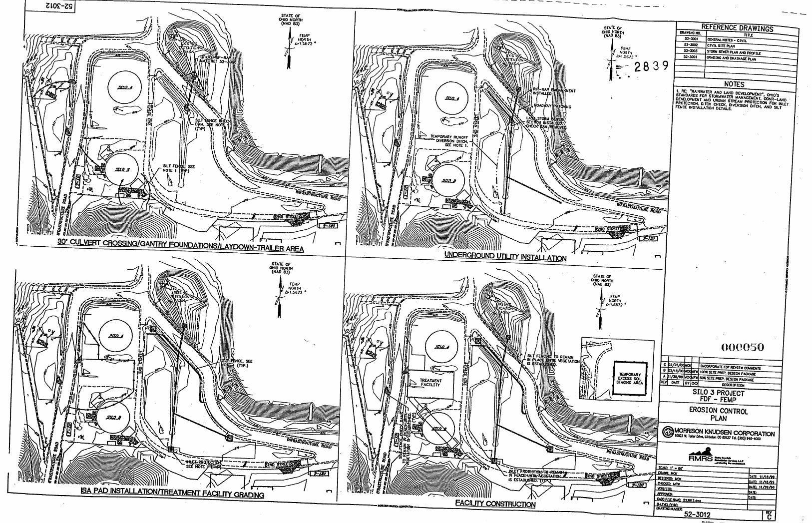
52-3002 - Civil Site Plan 52-3003 - Storm Sewer Plan and Profile 52-3004 - Grading and Drainage Plan 52-3012 - Erosion Control Plan 52-30 13 - ISA Pavement Plan and Sections 52-3014 - ISA-Pavement Details 52-3 0 16 - Sub-Basin Drainage Map 52-3020 - Underground Utilities Plan 52-3 1 10 - Silo Gantry Foundation Plan 52-3 11 1 - Silo Gantry Foundation Sections & Details 32-3 1 13 - Pipe Rack Foundation Plan 52-3 2 10 - Treatment Building Foundation Plan 52-321 1 - Treatment Building Concrete Sections & Details 52-3212 - Treatment Building Typical Sections & Details 52-3400 - W A C Foundation Plan and Sections
Februafy 25,2000 4 o f 5 General Description of the Work
OOP004;
1 2 3 4 5 6 7 8 9
10 11 12 13 14 15 16 17 18 19 20
:\!q::\.\ , '?1 <
Rocky Mountain Remediation Services, L L C 5 3 8 3 9 RMRS
-&?!a -
L - . - ... pmrullnp01. rmbnnment
54-3060 - Electrical Site Plan Lighting
7.0 LIST OF SPECIFICATIONS
Attachment C contains the following specification, which provide technical requirements for site preparation construction for the Silo 3 Project:
02210 - Earthwork/Gr2ding
02223 - Vegetative Layer
02900 - Seeding
02001 - Site Work General Provisions
02220 - Excavating and Backfilling for Foundations and Structures
02485 - Soil Erosion and Sedimentation Control
8.0 PORTABLE STRUCTURES INFORMATION
Attachments D and E provide typical manufacturers' data for the RUBB structure and portable trailers, respectively. Complete manufacturers' literature will be obtained when the units are procured.
February 25.2000 5 o f 5 General Descn'@on of the Work
OVP(3107

:- 2 8 3 9 . -
Rocky Mountain Remediation Services, L L C
-4 a . . . pmtrclfng the e m h m e n l
- RMRS
1 2 3 4 5 6 7 8 9
10 11 12 13
14
15
.._... .. ..... . . .. . .. .. - . .
ATTACHMENT A
Preoperational Environmental Control Plan
i OOC?OQ9
February 25,2000 Attachments General Description of the Work
RMRs Rocky Mountain Remediation Services, L.L.C. . . . protecting the environment
FERNALD SILO 3 PROJECT
Pre-Operational Environmental Control Plan
RMR-0445 -0060-00B
February 25,2000
Pre-Operational Control Plan RMR.0445.0060.008
4042&0445-G12 Rocky Mountain Remediation Services, LLC.
-4 4 - RMRS ... protutlng the rnrlmnnmni r- 2 8 3 9
TABLE OF CONTENTS
.. LIST OF ACRONYMS.. .................................................................................. .ii
1.0 PURPOSE .................................................................. .i ......................... 1
2.0
3.0
. EKCSlCN AND STOR.MWATER COXTR.@L. ?!.X?- ..................................... ..2
FUGITIVE DUST CONTROL PLAN ............................................................. 8
4.0 WASTE MANAGEMENT PLAN ................................................................ 13
5.0 REFERENCES ........................................................................................ 18
6.0 APPENDICES
Appendix A Appendix B Appendix C Appendix D Appendix E
Erosion and Stormwater Control Features Details Control of Fugitive Emission Daily Records Off-Hours Dust Control Procedure Material Segregation and Containerization Criteria Estimated Amounts of Each Type of Waste Stream
February 25,2000 Page i i Pre-OptEnvCtriPlan
Pre-Operational Control Plan RMR.0445.006O.OOB
4 O 4 2 0 4 4 4 ~ C 1 2
LIST OF ACRONYMS ? 2 8 3 9
. . ... . .
ACL BAT CERCLA CFR CM CWA DOE DPC E%,! FDF FEMP ISA MSDS MSCC MTL NAAQS ODNR ODOT OEPA OSDF OSHA PPE PECP RMRS RQ STD SWA SWMEC SWMECP TBD TSF WAC WSA
Administrative Control Level Best Available Technology Comprehensive Environmental Response, Compensation, and Liability Act Code of Federal Regulations Construction Manager Contractors’ Work Area Department of Energy Designated Primary Contact Environmental fi./isnagernPr+ Fluor Daniel Fernald Fernald Environmental Management Project Interim Storage Area Material Safety Data Sheet Material Segregation and Containerization Criteria Material Tracking Location National Ambient Air Quality Standards Ohio Department of Natural Resources Ohio Department of Transport Ohio Environmental protection Agency On-Site Disposal Facility Occupational Safety and Health Administration Personal Protective Equipment Pre-Operational Environmental Control Plan Rocky Mountain Remediation Services, L.L.C. Reportable Quantity Standard Subcontractor Work Area Surface-Water Management and Erosion Controls Surface-Water Management and Erosion Control Plan To Be Determined Treatment and Stabilization Facility Waste Acceptance Criteria Waste Storage Area
February 25,2000 Page iii PrPOptEnvCtrlPlan
Pre-Operational Control Plan RMR.0445.006O.OOB
40420-0445C-12 /
1
2 3
4
5 6
7
8
9
10
11 17
13
14
15 16 17
18
19
20
21
22 23
4
L5 26
1.0 PURPOSE I : " - 2 8 3 9
This Pre-Operational Environmental Control Plan (PECP) provides details of the methods and materials that RMRS and its subcontractors will use during the site preparation and construction phase of the Silo 3 Project to control erosion, stormwater, fugitive dust, contaminated soil, construction waste and minimize the impact of these activities on the environment. This plan covers the construction of the Interim Storage Area, the Silo 3 Retrieval Facility and the Treatment Facility at the US. Department of Energy (DOE) FEMP site, Fernald, Ohio. These areas are shown in RMRS Silo 3 Project Drawing Number 52-3002. The Silo 3 Project PECP contains the following plans:
Erosion and Stormwater Control: Descriptions of the methods and materials that will be used to prevent erosion of soil either by wind or surface water in the process or project work area and to reduce sediment loading in the stormwater. Descriptions of the methods, materials and existing site features that will be used to capture and control stormwater. Fugitive Dust Control: Descriptions of the methods and materials that will be used to suppress and minimize the creation and dispersion of dust. Waste Management: Description of the methods that will be used to manage waste and debris generated during site preparation and construction.
In Section 2.0 of the Silo 3 Project PECP the Erosion and Stormwater Control Plan is described; in Section 3.0 the Fugitive Dust Control Plan and in Section 4.0 the Waste Management Plan. Section 5.0 lists the references that have been used. These three plans comprise the key elements of the RMRS Pre-Operational Environmental Control Plan for the Silo 3 Project.
~~
February 25,2000 ~ ~~~
Page 1 of 18 Pre-OplEnvCtrlPlan
1 2
3 4
. 5
6
7 8 9
10
11 !Z
13 14
15 16
17 18 19
20
21
22 .‘ . ,% 43
$
25
26
27 28 29
30 31
32
33 34
35 36
37 38
39 40 41 42
43 44
Pre-Operational Control Plan RMR O445.0060.008
40420-0446G12
&- 2 8 3 9 2.0 EROSION AND STORMWATER CONTROL PLAN - -
Section 2.0 describes the RMRS Erosion and Stormwater Control Plan that will be used during the pre-operational phase of the Silo 3 Project including erosion control practices and surface water management that will be followed and implemented. This Plan addresses surface-water management and erosion control practices throughout the construction of the Interim Storage Area (ISA) and the Silo 3 Retrieval Facility and the Treatment Facilities, consistent with drawings and technical specifications detailed in the Site Preparation Package (RMR-0445- 0058). c
2.0 Functional Requirement of the Plan
The functional requirement of this Erosion and Stormwater Control Plan will satisfy the criteria outlined below:
Routing surface-water to designated locations where it can be appropriately managed Protecting Infrastructure Road, 2”d Street, Silo 3 and ISA construction areas from damage caused by precipitation and storm water run-on and run-off Discharging of surface-water into existing watercourses will be in accordance with applicable Ohio Department of Natural Resources (ONDR), Ohio Environmental Protection Agency (OEPA) and Department of Energy (DOE) directives and requirements Segregating clean area run-off from potentially contaminated area run-off. Contaminated stormwater will not be discharged with “clean” stormwater.
Functional requirements will be met by constructing the run-odrun-off control feature outlined below. Erosion control feature will be installed prior to any disturbance of soil in work areas. RMRS Silo 3 Project Drawing Number 52-3012 illustrates the location and limits of the control features.
These include, but are not limited to, the following nine control features:
Installation of silt fences on the down slope sides of the construction areas Construction of sediment traps as required Installation of silt fences below sump discharges where applicable Installation of temporary culverts along roads next to construction site as required Installation of check dams in drainage channels and swales as required Installation of additional permanent riprap as required Construction of necessary drainage channels as shown in Drawing number 52-3012 Maintenance, repair or replacement of existing surface water and erosion control features as required Excavations, which are expected to be inactive for 45 days or more, will be stabilized within 7 days of their final use Dewatering
hbNary 25, 2000 Page 2 of 18 Pre-Op fEnvCtrlPlan
1
2
3
4
5
6
7
8
9
10
11
12
13
14
15
16
17
18
19
20
21
22
'3
-4
25
26
27
28
29
30
31
32
33
34
35
36
37
38
39
40
41
\. " \
Pre-Operational Control Plan RMR.0445.006O.OOB
40420-0445C-12 = 2 8 3 9
The type and location of erosion control features will be subject to adjustment depending on field conditions. As described in RMRS Technical Specification 02485, RMRS will routinely inspect and evaluate the effectiveness of, and need for maintenance of the control measures that are in place.
2.2 Run-On/Run-Off Control Structural Practices
Process design and operation will minimize the potential for generation of contaminated stormwater, including any run-on and run-off. A description of the construction, inspection and maintenance of the run-odm-off control feature is presented in this section. These features may include, but will not be limited to:
drainage channels and swales checkdams culverts silt fences diversions.
Any repairs to the erosion and stormwater control measures will be corrected by RMRS within 24 hours of the problem being discovered. Areas of excavation, and all erosion control measures will be inspected by RMRS to verify that they are installed in accordance with RMRS Technical Specification 02485, and are still fimctioning properly. An inspection checklist will be developed by RMRS in support of the inspection schedule. Disturbed areas will also be inspected for evidence of excessive erosion or siltation. These inspections will occur, at a minimum, at the following frequency:
weekly for general inspections 0 daily after each rain event exceeding 0.5 inches at the site
at least once per day during prolonged rainfall events at the site.
Inspections will be documented in the RMRS Daily Activity Report at the Silo 3 Project site. These records will be made available to FDF for review upon request. This inspection frequency is in addition to any specific requirements identified in the 'Inspection and Maintenance' requirements for each control measure below.
2.2.1 Temporary Drainage Channels and Swales
Where applicable, temporary drainage channel and swales will be constructed between control points on predefined lines and grades. Temporary drainage channels and swales will be stabilized in accordance with the RMRS Technical Specification Number 02485, Soil Erosion and Sedimentation Control.
February 25,2000 Page 3 of 18 Pre-OptEnvCtrWan
1
2
3
4
5
6
7
8
9
10
l!
12
13
14
15
16
17
18
19
20
21
22
.- ‘\\ % ?3
4
25
26
27
28
29
30
31
32
33
34
35
36
37
38
39
40
41
42
43
44
45
e6
Pre-Operational Control Plan RMR 0445.0060.008
40420-0445.C-72
. . =- 2 8 3 9 Inspection and Maintenance
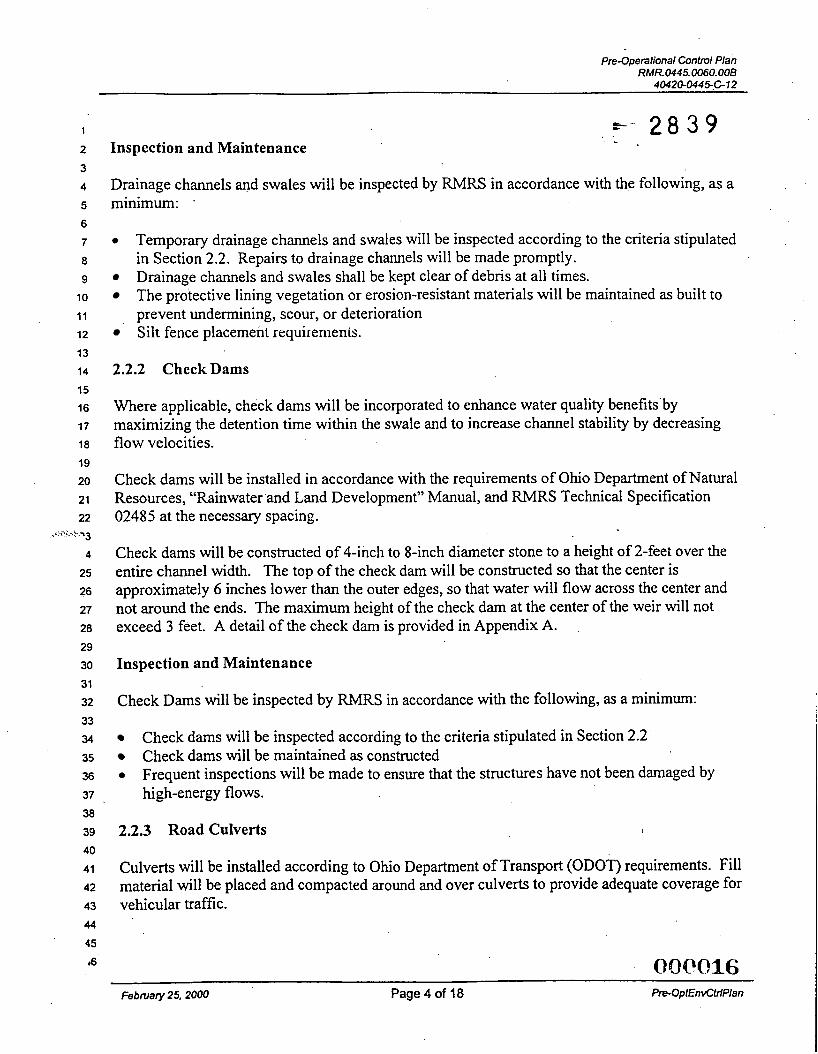
Drainage channels and swales will be inspected by RMRS in accordance with the following, as a minimum: .
0
Silt fence placement requiremenis.
Temporary drainage channels and swales will be inspected according to the criteria stipulated in Section 2.2. Repairs to drainage channels will be made promptly. Drainage channels and swales shall be kept clear of debris at all times. The protective lining vegetation or erosion-resistant materials will be maintained as built to prevent undermining, scour, or dcterioration
2.2.2 Check Dams
Where applicable, check dams will be incorporated to enhance water quality benefits’by maximizing the detention time within the swale and to increase channel stability by decreasing flow velocities.
Check dams will be installed in accordance with the requirements of Ohio Department of Natural Resources, “Rainwater and Land Development” Manual, and RMRS Technical Specification 02485 at the necessary spacing.
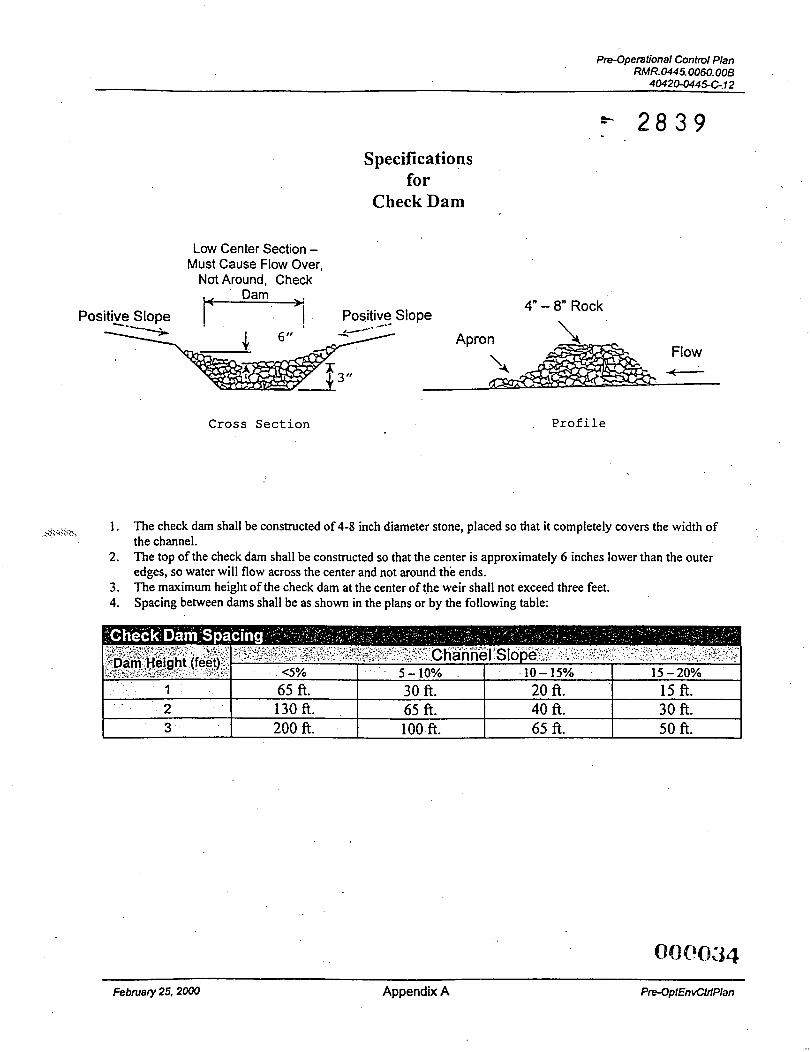
Check dams will be constructed of 4-inch to 8-inch diameter stone to a height of 2-feet over the entire channel width. The top of the check dam will be constructed so that the center is approximately 6 inches lower than the outer edges, so that water will flow across the center and not around the ends. The maximuni height of the check dam at the center of the weir will not exceed 3 feet. A detail of the check dam is provided in Appendix A.
Inspection and Maintenance
Check Dams will be inspected by RMRS in accordance with the following, as a minimum:
0
Check dams will be inspected according to the criteria stipulated in Section 2.2 Check dams will be maintained as constructed Frequent inspections will be made to ensure that the structures have not been damaged by high-energy flows.
2.2.3 Road Culverts 1
Culverts will be installed according to Ohio Department of Transport (ODOT) requirements. Fill material Will be placed and compacted around and over culverts to provide adequate coverage for vehicular traffic.
08@016 February 25,2000 Page 4 of 18 PrPOptEnvCtrlPlan
pre-Operational Control Plan RMR0445.0060.00B
40420-0446C12
1
2
3
4
5
6
7
8
9
10
11
12
13
14
15
16
17
18
19
20
21
22 < : \.‘ 13
4
25
26
27
28
29
30
31
32
33
34
35
36
37
38
39
40
41
Inspection and Maintenance 7- 2 8 3 9
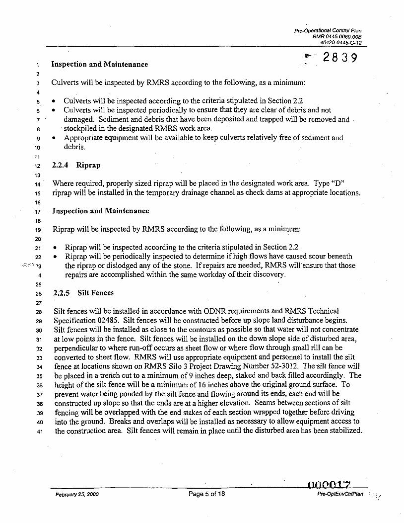
Culverts will be inspected by RMRS according to the following, as a minimum:
Culverts will be inspected according to the criteria stipulated in Section 2.2 Culverts will be inspected periodically to ensure that they are clear of debris and not damaged. Sediment and debris that have been deposited and trapped will be removed and stockpiled in the designated RMRS work area. Appropriate equipment will be available to keep culverts relatively free of sediment and debris.
’
2.2.4 Riprap
Where required, properly sized riprap will be placed in the designated work area. Type “D” riprap will be installed in the temporary drainage channel as check dams at appropriate locations.
Inspection and Maintenance
Riprap will be inspected by RMRS according to the following, as a minimum:
Riprap will be inspected according to the criteria stipulated in Section 2.2 Riprap will be periodically inspected to determine if high flows have caused scour beneath the riprap or dislodged any of the stone. If repairs are needed, RMRS will’ensure that those repairs are accomplished within the same workday of their discovery.
2.2.5 Silt Fences
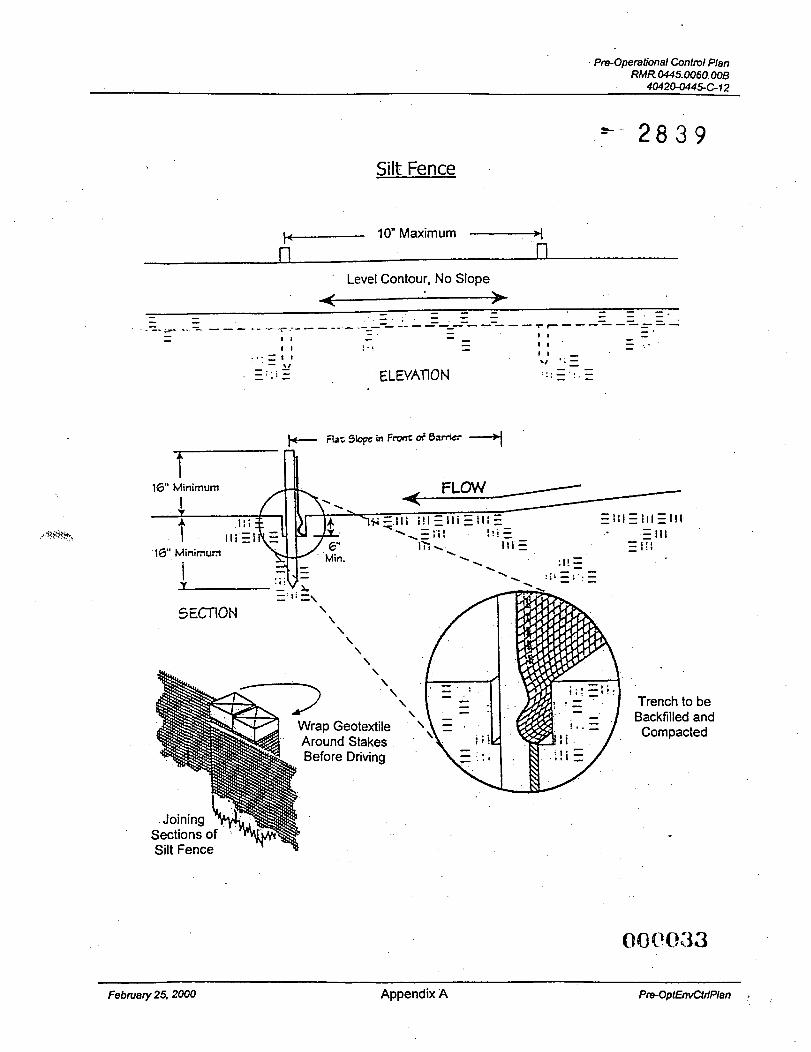
Silt fences will be installed in accordance with ODNR requirements and RMRS Technical Specification 02485. Silt fences will be constructed before up slope land disturbance begins. Silt fences will be installed as close to the contours as possible so that water will not concentrate at low points in the fence. Silt fences will be installed on the down slope side of disturbed area, perpendicular to where run-off occurs as sheet flow or where flow through small rill can be converted to sheet flow. RMRS will use appropriate equipment and personnel to install the silt fence at locations shown on RMRS Silo 3 Project Drawing Number 52-3012. The silt fence will be placed in a trench cut to a minimum of 9 inches deep, staked and back filled accordingly. The height of the silt fence will be a minimum of 16 inches above the original ground surface. To prevent water being ponded by the silt fence and flowing around its ends, each end will be constructed up slope so that the ends are at a higher elevation. Seams between sections of silt fencing will be overlapped with the end stakes of each section wrapped together before driving into the ground. Breaks and overlaps will be installed as necessary to allow equipment access to the construction area. Silt fences will remain in place until the disturbed area has been stabilized.
QQP(?4 Y February 25,2000 Page 5 of 18 Pre-OptEnvCtriPlan 1 :,,,
, 2 3 4
5 6 7
8
9 10
1 1
12
13 14
15 16
17 18
19 29
21 22
. '3 .4
25
26
27 28 29 30 31 32 33
34 35 36 37 38
39 40
41
42 43 44
45 16
Pre-Operational Control Plan RMR.0445.0060.008
4O42GO445612
Inspection and Maintenance
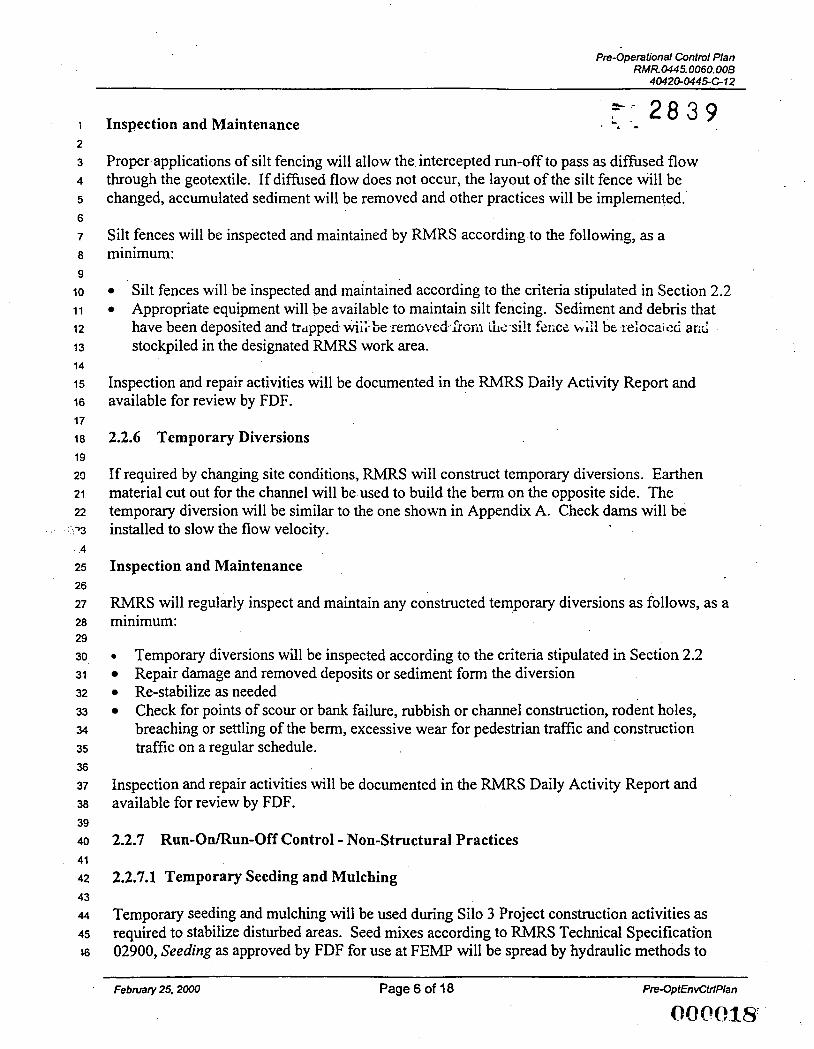
Proper applications of silt fencing will allow the intercepted run-off to pass as diffused flow through the geotextile. If diffused flow does not occur, the layout of the silt fence will be changed, accumulated sediment will be removed and other practices will be implemented.
Silt fences will be inspected and maintained by RMRS according-to the following, as a minimum:
0
0
Silt fences will be inspected and maintained according to the criteria stipulated in Section 2.2 Appropriate equipment will be available to maintain silt fencing. Sediment and debris that have been deposited and trdppeci wii; be :moved h f i i ik silt f&iCZ stockpiled in the designated RMRS work area.
be ieloeaicd arii
Inspection and repair activities will be documented in the RMRS Daily Activity Report and available for review by FDF.
2.2.6 Temporary Diversions
If required by changing site conditions, RMRS will construct temporary diversions. Earthen material cut out for the channel will be used to build the berm on the opposite side. The temporary diversion will be similar to the one shown in Appendix A. Check dams will be installed to slow the flow velocity.
Inspection and Maintenance
RMRS will regularly inspect and maintain any constructed temporary diversions as follows, as a minimum:
0
0 Re-stabilize as needed
Temporary diversions will be inspected according to the criteria stipulated in Section 2.2 Repair damage and removed deposits or sediment form the diversion
Check for points of scour or bank failure, rubbish or channel construction, rodent holes, breaching or settling of the berm, excessive wear for pedestrian traffic and construction traffic on a regular schedule.
Inspection and repair activities will be documented in the RMRS Daily Activity Report and available for review by FDF.
2.2.7 Run-On/Run-Off Control - Non-Structural Practices
2.2.7.1 Temporary Seeding and Mulching
Temporary seeding and mulching will be used during Silo 3 Project construction activities as required to stabilize disturbed areas. Seed mixes according to RMRS Technical Specification 02900, Seeding as approved by FDF for use at FEMP will be spread by hydraulic methods to
February 25. 2000 Page 6 of 18 Pre-OptEnvCtrlPlan
004r018'
1 2
3 4
5 6 7
8 9
10 11 12
13 14
15 16
17 18
19 20 21 22
: ; ,<< <r)3
.4
25 26 27 28
29
30 31 32
33 34
35 36
37 38
Pre-Operational Control Plan
40420-0449C-12 7 - 2 8 3 9 R M R . ~ ~ ~ ~ . ~ ~ o . o o B . -
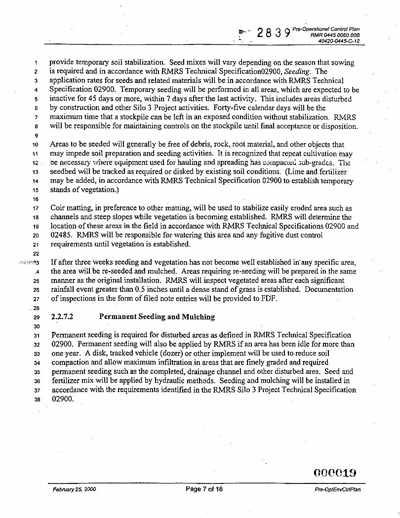
provide temporary soil stabilization. Seed mixes will vary depending on the season that sowing is required and in accordance with RMRS Technical Specification02900, Seeding. The application rates for seeds and related materials will be in accordance with RMRS Technical Specification 02900. Temporary seeding will be performed in all areas, which are expected to be inactive for 45 days or more, within 7 days after the last activity. This includes areas disturbed by construction and other Silo 3 Project activities. Forty-five calendar days will be the maximum time that a stockpile can be left in an exposed condition without stabilization. RMRS will be responsible for maintaining controls on the stockpile until final acceptance or disposition.
Areas to be seeded will generally be free of debris, rock, root material, and other objects that may impede soil preparation and seeding activities. It is recognized that repeat cultivation may
seedbed will be tracked as required or disked by existing soil conditions. (Lime and fertilizer may be added, in accordance with RMRS Technical Specification 02900 to establish temporary stands of vegetation.)
be necessary -.:.?iere cquipment used for hauling and spreading has cmipac:ei ;ub-gr&s. 'F Iic
Coir matting, in preference to other matting, will be used to stabilize easily eroded area such as channels and steep slopes while vegetation is becoming established. RMRS will determine the location of these areas in the field in accordance with RMRS Technical Specifications 02900 and 02485. RMRS will be responsible for watering this area and any fugitive dust control requirements until vegetation is established.
If after three weeks seeding and vegetation has not become well established in-any specific area, the area will be re-seeded and mulched. Areas requiring re-seeding will be prepared in the same manner as the original installation. RMRS will inspect vegetated areas after each significant rainfall event greater than 0.5 inches until a dense stand of grass is established. Documentation of inspections in the form of filed note entries will be provided to FDF.
2.2.7.2 Permanent Seeding and Mulching
Permanent seeding is required for disturbed areas as defined in RMRS Technical Specification 02900. Permanent seeding will also be applied by RMRS if an area has been idle for more than one year. A disk, tracked vehicle (dozer) or other implement will be used to reduce soil compaction and allow maximum infiltration in areas that are finely graded and required permanent seeding such as the completed, drainage channel and other disturbed area. Seed and fertilizer mix will be applied by hydraulic methods. Seeding and mulching will be installed in accordance with the requirements identified in the RMRS Silo 3 Project Technical Specification 02900.
February 25,2000 Page 7 of 18 Pre-OptEnvCtdPIan
pre-Operational Control Plan RMR. 0445.OO60.008
40420-0445612
1
2
3
4
5
6
7
8
9
10
11
12
13
14
15
16
17
18
19
20
21
22
*.‘‘‘\ “3
-4
25
26
27
28
29
30
31
32
33
34
35
36
37
3a
39
40
41
42
43
44
45
= 2 8 3 9 - 3.0 FUGITIVE DUST CONTROL PLAN
This Fugitive Dust Control Plan describes the methodology that will be used by RMRS for controlling fugitive dust emissions and ensuring compliance with the required standards and site specific limits for the Silo 3 Project. RMRS will proactively suppress dust releases from field activities by applying Best Available Technology (BAT) dust control materials and/or implementing BAT work practices either at the beginning and during field activities. RMRS will use FDF, RM-0047, Fugitive Dust Control Requirements, as the appropriate site-specific definition of BAT for fbgitive dust control together with OAC 3745-17-07 and OAC 3745-17- 08, BAT to minimize the creation and dispersion of fugitive dust.
3.1 Site-Specific Limits
RMRS will apply the following Site-Specific Limits:
0
Visible particulate emission from any paved roadway or paved parking area should not exceed one minute during any sixty-minute observation period. Visible particulate emissions from any unpaved roadway, unpaved parking area, project field activities, or wind erosion from storage piles should not exceed three minutes during any sixty-minute observation period.
Qualified RMRS personnel using 40 CFR Part 60 Appendix A, Method 22 “Visual Determination of Fugitive Emission from Material Sources and Smoke Emissions for Flares will verify compliance with these limits.” FDF will provide “Method 22” training to qualify RMRS personnel.
3.2 Suppression Equipment
Due to the radiological issues associated with working on the Silo 3 Project, RMRS intends to use dedicated equipment for their radiological work zones to avoid potential decontamination requirements. If required by site conditions, RMRS may, after decontamination and radiological scanning, switch equipment and systems between areas. The proposed equipment list to suppress dust releases includes, but is not limited to, the following:
Motor Grader Backhoe Miscellaneous Hand tools (shovels, brooms) Miscellaneous Pumps and Hoses Skid Steer Loader with Broom Attachment (for road crossing only if water flushing and hand wet brooming is ineffective) Water Wagon Smooth Drum Roller
February 25,2000 Page 8 of 18
4
2 3 4
5 6 7 8
9 10
11
12
13 14 15
16 17 18 19 20 21 22
. < \ .73
4
25 26 27
28 29
30
31 32
33 34
35 36
37 38
39 40 41 42
43 44
45
ptt+Operational Control Plan RMR. 0445.0060.008
4O426O445C-12
3.3 Methods and Materials *- 2 8 3 9 At the beginning of each day and periodically throughout that day, project personnel will tour the Silo 3 Project site, applying BAT Fugitive Dust Controls and/or other work practices to identify control and thereby minimize dust generation. Before fugitive dust emissions are visible, BAT hgitive dust controls andor work practices will be implemented or increased. If the visible limit is exceeded, i.e., visible particulate emissions from any paved roadway or paved parking area exceeding one minute during any sixty-minute observation period or visible particulate emissions from any unpaved roadway, unpaved parking area, project field activities, or wind erosion from storage piles exceeding three minutes duration during any sixty-minute period, then mechanical dust generating activities must cease immediately. An increase of BAT dust cmtrols and/’or work practices wiii be instigated or incieased 10 b&;g the fugitive emissicn, as a minimum, below the visible limit during the dust generating activities. Additionally, BAT dust controls and/or work practices will be implemented at the end of each day in order to minimize the occurrences of off-hours dust alert. Specific materials and methods may include the following:
Water
Plastic Sheeting or Tarps Revegetation Materials.
Crusting agents such as Pine Sap Emulsion@ or equivalent (as approved by FDF)
3.4 Work Practices
RMRS and FDF will continuously monitor project field activities for visible emissions. RMRS will be responsible fur implementing, directing and coordinating BAT work practices to monitor project field activities for visible emissions. Specific work practices may include the following:
Effective “Wheel Washing” prior to entering the paved area andor as required by contamination control ~
Application of dust suppression materials (mainly water) to active work areas or other areas where dust is likely to be generated Before the end of shift, sealing off (by rolling, grading or compacting) work areas stockpiles, working piles, etc. where fugitive emissions are likely to occur if not sealed During dry conditions or as needed initiating dust control prior to start of shift and during lunch break Wet sweep, blade or otherwise remove any clods, clumps, tracks, or other deposits of soil of mud from paved roadways and parking area, applying appropriate dust control measures to suppress the generation of visible dust that may result form the removal process Using alternative routing for hauling of materials Changing method of excavation when feasible including reducing the rate of excavation Maintaining roadway shoulders Minimizing unnecessary traffic Adhering to site specific speed limits of 15 mph on paved surfaces and 10 mph on unpaved and if necessary, further reduce the speed of equipment and hauVother site vehicles . i‘ .
OOQ‘Ofz1 February 25.2000 Page 9 of 18 Pre-Op EnvCfdPlan
1
2
3
4
5
6
7
8
9
10
11
12
13
14
15
16
17
18
19
20
21
22 - % -03
4
25
26
27
28
29
30
31
32
33
34
35
36
37
38
39
40
41
42
43
Pre-Operational Control Plan RMR. 0445.0060. OOB
4042O-CM45.C-12 e- 2 8 3 9
Applying water or other appropriate dust suppression agents to material being transported and cover truck beds when material is still likely to become airborne Utilizing load covers during periods of equipment movement, regardless of truck being empty or full Minimizing configuration of material being hauled (Le., place less material in haul vehicle) Minimizing drop height during loading and unloading If practical, cover small storage piles with tarps or plastic sheeting For extended periods of planned inactivity, vegetate as a last resort, if protective cover or periodic application of surfactants or crusting agents prove ineffective Repair or resurface roadwaydparking areas as needed or use an alternative road surface as a last resort.
3.5 Implementation of the Fugitive Dust Control Plan
RMRS will be responsible for implementing, directing and coordinating the Silo 3 Project Fugitive Dust Control Plan. RMRS will communicate the information contained in this plan to their workforce through a pre-task briefing and through other periodic briefings as required. These briefings will be documented. Those workers who will have specific dust suppression duties will be briefed to the special record keeping requirements of this task.
RMRS responsibilities include, but are not limited to the following:
0
0
0
8
e 0
e 0
3.6
Briefing field personnel Monitoring for visible emissions Directing of BAT suppression activities Receiving opacity monitoring inforniation from FDF personnel Coordinating maintenance and repair of equipment and systems components Directing of alternative work practices when required Overseeing the record keeping process and maintaining permanent records Stopping field activities of fugitive dust limits are exceeded and coordinating the restart of the activity with FDF personnel after corrective measure have been implemented. Site Specific Limits are defined in Section 3.1 of the Pre-Operational Environmental Control Plan.
Monitoring
All personnel, who have been briefed on this plan, will report suspected fugitive dust emissions to the appropriate RMRS personnel who will then direct the implementation of BAT work practices and fugitive dust control. As outlined in Section 3.4, RMRS will, together with FDF personnel, regularly monitor field conditions for visible dust emission. RMRS will also communicate with FDF personnel regarding information gathered for the FDF Opacity Monitoring activities. When required, BAT material will be applied and BAT work practices will be implemented to limit fugitive dust emissions.
February 25,2000 Page 10 of 18
1
2
3
4
5
6
7
8
9
10
11
.i i 13
14
15
16
17
18
19
20
21
22 \I -23
.4
25
26 27
28
29.
30
31
32
33
34
35
36
37
38
39
40
41
42
43
44
45 16
Pre-Operational Control Plan RMR.0445.006O.OOB
4042(FO44SC12
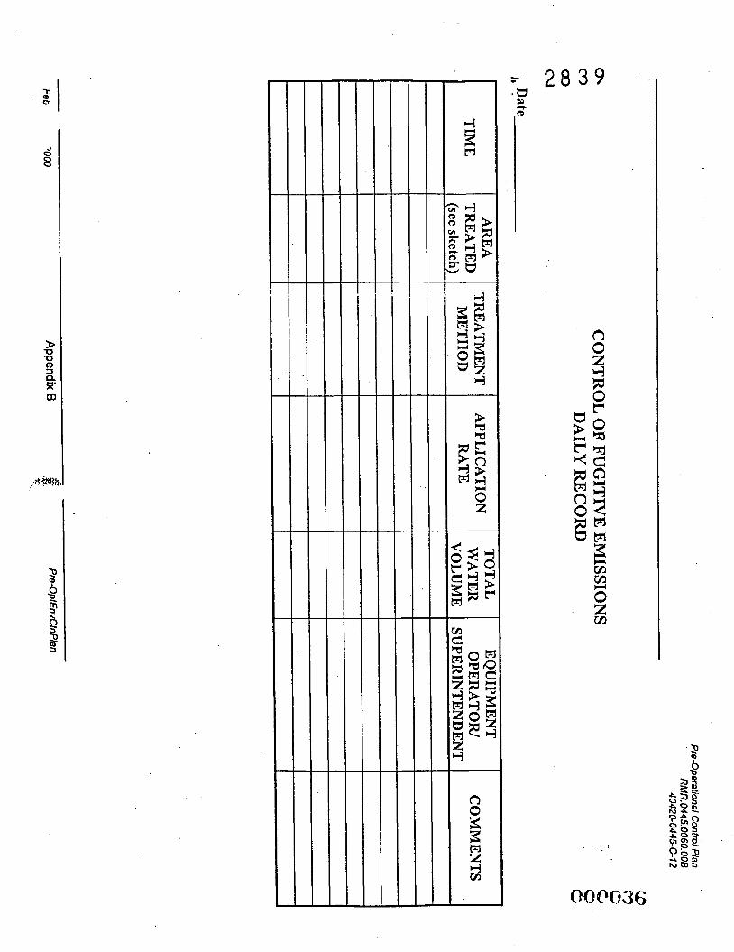
3.7 Record Keeping = 2 8 3 9
The record keeping process will begin with the RMRS Silo 3 Project Field Supervisors/ Managers, who will brief those workers applying BAT materials pursuant to the required record keeping. The form to be filled out can be found in Appendix B. Appropriate personnel will complete these forms. Completed forms will be part of the Silo 3 Project Daily Activity Report and will be filed in the permanent project files and transmitted to FDF when requested. Additional blank copies of the forms will be kept in the cabs of the equipment and in the field trailer. Completed forms will be turned over to the RMRS Silo 3 Project Field Supervisors on a daily basis. Forms will be reviewed for completeness and incomplete forms will be returned to the appropriate individual for corrections. Failure of an individual to consistently produce complete aid accurate records will result in discipiiiicuy action.
3.8 Off-Hours Fugitive Dust Alert Notification
A “Dust Alert” is defined as when excessive or visible dust emanates from anywhere within the Contract Work Area during non-working periods. “Non-Work” periods are defined as hours when neither RMRS nor any subcontractor is performing Silo 3 construction activities on site. However, the FEMP remains staffed by FDF Security personnel twenty-four (24) hours per day. RMRS or FDF will have Silo 3 Project trained personnel on-call during non-work periods, seven (7) days per week (including holidays) to respond to any off-hours fugitive dust alert. These personnel are not trained to implement fugitive dust controls. Therefore, if visible dust is observed within the Work Area during project non-work periods, FDF will notify RMRS. Dust suppression will begin within two (2) hours of notification by FDF.
3.8.1 Notification Procedure
During a Dust Alert, FDF will refer to the “Off-Hours Dust Alert Schedule” that will be provided by RMRS prior to initiation of construction activities. If FDF cannot contact the RMRS Designated Primary Contact (DPC) within a reasonable time frame, an attempt to reach the designated alternative contact will be made. Similarly, if the alternative cannot be expeditiously contacted, the second alternative will be contacted. In the unlikely event that all three of these individuals cannot be reached, FDF will attempt to contact any other person identified on the RMRS approved contact list.
Upon receiving notification from FDF, the RMRS DPC will then contact qualified personnel, as appropriate, to respond to the Dust Alert. The RMRS DPC must verify that those responding to the “Off-Hours Dust Alert” are able to gain access to a controlled area if required. Only those personnel who meet the appropriate training and medical requirements for this work should be contacted. The RMRS DPC, as well as those personnel contacted, will go to the site to direct the work and implement the necessary corrective actions. Due to the nature of dust suppression being defined as a Limited Scope Work, RMRS is not required to have the Site Health and Safety Officer respond to these Dust Alerts. FDF will provide any necessary safety coverage. The proposed RMRS internal Off-Hour Dust Control Procedure is attached as Appendix C of this plan.
083PQ23 February 25,2000 Page 11 of 18 Pre-Opt€nvCIdP/an
1
2
3
4
5
6
7
a 9
10
11
12
13
14
15
16
17
18
19
20
21
22
Pre-Operational Control Plan RMR. 0445.OO60.00B
40420-0445G12
E- 2 8 3 9 3.8.2 RMRS Site Response
RMRS personnel will utilize adequate BAT dust control methods to bring any hgitive dust emissions to below the Site-Specific Limit during dust generating activities. Designated RMRS personnel will not leave the Silo 3 Project site without concurrence from FDF that sufficient controls are in place or until FDF has signed the Dust Alert Work Order included in Appendix C.
3.8.3 Schedule and Contacts
The Off-Hours Dust Alert Schedule and Contact List will be provided to FDF prior to the start of RMRS Silo 3 Project construction activities.
February 25,2000 ~~ ~
Page 12 of 18
Pre-Operational Control Plan RMR. 0445.0060.00B
4042G0445C12
I
2
3
4
5
6
7
8
9
10
11
12
13
14
15
16
17
18
19
20
21
22
* * ‘ ”3
.4
25
26
27
28
29
30
31
32
33
34
35
36
37
38
39
40
41
42
43
44
45
4.0 WASTE MANAGEMENT PLAN F- 2 8 3 9
The purpose of the Waste Management Plan is to describe the materials and methodology RMRS will use to support safe construction including careful removal and disposition of relevant waste materials. Management of secondary wastes generated as a result of the Silo 3 Project construction activities will be consistent with FDF site procedures and applicable regulatory drivers.
4.1 Waste Types
It is expected that RMRS construction activities will generate three main groups of secondary waste materials, i.e., ciean collstruciion debris, radioiogically contaminated construLiion debris and excavated soil. Smaller quantities of additional solid waste, e.g., personnel protection equipment, wood, and potentially some drums are anticipated. Clean construction debris is material which as a result of construction has been brought onto the Silo 3 Project site by RMRS or is created by construction activities, and has been surveyed or characterized and released by FDF as non-radioactive and non-hazardous waste. Radiological contaminated construction debris is material that has been contaminated during construction by whatever means inside the Controlled Area. Excess excavated soil will be generated as a consequence of earthwork, particularly from the construction of the ISA pad.
There is also the potential that RMRS will encounter some unknown debris during soil excavation. This material may be manufactured objects or natural solid waste: These items will be dealt with on an item by item basis at the time of discovery. FDF will be responsible for characterizing and approving the ultimate disposition of this material.
RMRS will manage all excavated soil per FDF guidance as stated herein.
Waste oils, engine coolants, hydraulic fluids and other lubricants from the servicing of equipment have not been identified as a “waste stream” as these items will not be stored on the site. Vehicle and construction equipment maintenance will be done off-site. On-site failure of equipment or vehicles will be managed on an item by item basis following approval by FDF and in accordance with FDF ACR-007, Waste Materid Handling Criteria for Construction Projects. Any accident spill of these materials will be subject to FDF spill notification requirements. RMRS will conduct weekly inspections of fuel storage tanks and equipment.
Any chemicals brought on-site by RMRS or its subcontractors will be approved in advance by FDF. When RMRS requires liquids (such as paints, thinners, caulks etc.) Material Safety Data Sheets (MSDS) will be submitted to FDF for each item at least 10 calendar days prior to their usage on-site. FDF ACR-007 lists those items which are prohibited from being brought onto FEMP.
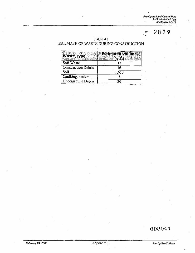
An estimate of the amount of each type of waste stream is given in Table 4-1.
February 25,2000 Page 13 of 18 Pre-OptEnvCtrff /an
Pre-Operational Control Plan RMR. 0445.0060.008
4042CW449C12
1
2
3
4
5
6
7
8
9
10
11
12
13 14
15
16
17
18 19
20 21
22 . 23
’4
25
26
27
28 29
30
31
32
33
34
35
36
37
38
39
40
41
42
43
44
.i\ ,:+.
4.2 Waste Minimization 5 - 2 8 3 9 RMRS will make every effort to minimize waste generation by limiting the amount of material that enters the Controlled Area whenever possible. Material wrapping and packaging will be minimized on-site by requesting that suppliers provide material with as little packaging as possible. Where feasible assembly of equipment modules will be done off-site. Pre-job planning will be used to ensure that the number of tools identified and the equipment needed to complete the job are minimized. RMRS will not bring any hazardous materials into the Controlled Area unless absolutely necessary and only with the prior approval of FDF. RMRS does not intend to do any vehicle or equipment maintenance on-site. This does not rule out any emergencyhreakdown maintenance that may be required. RMRS will contact FDF for guidelines on on-sire controls ma wask disposition for any emergency vehicle maintalance activities on a case by case basis.
It is expected that only small quantities of “hazardous” materials (e.g., pipe sealants, concrete sealants, marking paints, caulking materials) will be required for the Silo 3 Project construction activities. To minimize the amount of this type of waste, only that quantity which is required to complete the job will be brought on-site.
4.3 Construction Debris Management
RMRS will set aside construction debris generated in predetermined locations and install controlled boundaries to define each area as well as limit access to them. FDE Radiological Control will survey the debris and determine if it meets the free-release criteria specified by FDF Site Procedure FW-0009, Radiological Requirements for the Release of Materials at the FEMP. FDF will be responsible for determining whether waste generated by RMRS is either radiologically contaminated, hazardous or clean construction waste. The waste will be segregated by RMRS based on their determination.
Construction wastes such as fencing will be cleaned of soils awaiting radiological survey to ensure that it meets the free-release criteria.
Construction debris that does not meet the free-release criteria for the site will be segregated and containerized into waste streams. RMRS and FDF project personnel will be briefed on the waste segregation and size-reduction criteria for the Silo 3 Project prior to mobilization. The estimated volume of secondary waste from construction activities, underground material, soft waste and caulkinghealants is estimated to be no greater than 62yd3. The estimated amount of each waste type is given in the table in Appendix E.
FDF will arrange for the delivery and pickup of containers of contaminated construction debris only. FDF personnel will track the volume of contaminated waste generated by the Silo 3 Project construction activities. RMRS will be responsible for minimizing the amount of “free-releasable” waste, tracking the total volume generated and for its final off-site disposition.
February 25, 2000 Page 14 of 18 Pre-OptEnvCtrlPlan
2
3 4
5
6
7
8
9
1G
11 a- IL
13
14
15
16
17
18
19
20
21
22
.\ 73 4
25
26
27
28
29
30
31
32
33
34
35
36
37
38 39
40
41
42
43
44
45
46
Pre-Operational Control Plan RMR.0445.0060.00B
4042W445C12
FDF will be responsible for the appropriate disposition of unused chemicals and any empty chemical containers. FDF will provide RMRS with technical direction on the tem or of these materials. 8 YsBrY9 4.4 Soil Management
During site preparation, particularly construction of the ISA pad, RMRS has estimated that they will generate approximately 1,650 yd3 of ‘cut’ volume and 290 yd3 of ‘raw fill’ soil. The ‘cut’ volume will be monitored and dispositioned as excess waste according to FDF requirements. The soil staging area is identified on Silo 3 Project Drawing Number 52-3002. Erosion controls will be installed in accordance with RMRS Technical Specification 02485 prior to placement of so:! :E t k stagicg ai::. Tf?c :;A 922 Y F ~ ! k maintained in accordance with RMRS Tec!-,~~ic~! Specification 02210. Earthwork and related activities will not be performed during unfavorable weather conditions, e.g., rain, snow or high winds. Soil management will comply with the Silo 3 Project Health and Safety Plan, the Erosion and Stormwater Control Plan and the Fugitive Dust Control Plan. Excess soil will be dispositioned as soon as practical post excavation. Transportation of the soil to the OSDF will be the responsibility of FDF. The OSDF subcontractor will transport the soil as soon as practical. The schedule for transportation of the soil will be dependent upon the OSDF availability and the OSDF subcontractor’s transportation schedules. It is expected that transportation of the excess soil to the OSDF will be completed within 45 days of completing excavation.
. .
Previously gathered data from the FEMP Infrastructure Project indicates that soil in the area of the proposed Silo 3 Project meets the Waste Acceptance Criteria (WAC) for the On-site Disposal Facility. RMRS will report the final volume of excess soil generated to FDF at the end of each normal working day.
Should additional sampling and characterization or real-time readings of the soil conducted during excavation indicate that the soil might exceed the FEMP WAC, it must be managed in one of two manners:
0 Option 1: In the event that additional sampling indicates RCRA characteristic waste in the area, RMRS or its subcontractors will place the suspected waste in boxes. FDF will provide delivery and pickup of the boxes and will track the volume of soil excavated. RMRS will be responsible for ensuring that the weight restriction of the boxes is not exceeded. FDF will provide a scale for these activities.. If RCRA characteristic waste is identified, none of the associated soil will be used as fill.
In the event that additional sampling and characterization or real-time readings indicates elevated levels of Total Uranium and/or Technetium-99 are present in the soil, i.e., the soil exceeds the FEMP WAC, RMRS will transport all such soil to a temporary working
report to FDF the volumes of soil transported to this temporary-working stockpile. Above- WAC soil will not be used as fill.
0 Option2:
stockpile. RMRS will lay down geotextile and install silt fence around the pile. RMRS will a , -
(30N?27 February 25,2000 Page 15 of 18 PrPOptEnvCtriPlan
1
2
3
4
5 6
7
8
9
13 11 .-l I&
13 14
15
16
17
18
19
20
21
22
23 ,,, I \
‘ 4
25 26
27
28
29
30
31
32
33
34
35
36 37
38 39
40
41
42
43
44
45
46
47
Pre-Operational Control Plan RMR.0445.006O.OOB
40420-0445612
z- 2 8 3 9 If either Option 1 or 2 has to be exercised, FDF will demarcate the area fo-be kxcavated and transported or boxed. FDF will establish Material Tracking Locations (MTLs) and provide RMRS with a site map indicating where these MTLs are located. FDF will be responsible for tracking this soil by MTL including the.volumes reported by RMRS.
To minimize erosion, RMRS will supply a plastic tarp or similar barrier to cover the soil while it is awaiting radiological survey to minimize erosion. Material, which is wet, muddy or covered with snow or ice, cannot be properly surveyed for unrestricted release. Any cleaning required to facilitate the survey will be done by RMRS. An additional barrier may be placed on the ground underneath the waste material if deemed necessary by RMRS or FDF. FDF Radiological Cmtrsl -;.-ill deternix Jf azy zd2I;ioaal pxcsutions are necessary depending on the physk! ~ q d . radiological conditions of the laydown area.
RMRS will segregate the generated waste materials and protect them from the weather as necessary in accordance with RMRS Technical Specification 02485. If necessary, precautionary measures against spillage such as the installation of berms will be actioned in the field by RMRS. Surface water will be directed away from any stockpile site to minimize erosion deterioration. Stormwater run-off controls will be provided to prevent sediment from leaving any stockpile area. Perimeters to each stockpile will have proper sediment controls and any other run-off controls considered appropriate for the prevailing field conditions. RMRS will be responsible for maintaining controls in these areas until final acceptance or disposition has been determined; including controlling any dust emissions and grading needed on adaily basis.
4.5 Unknown Debris Management
During excavation, RMRS may encounter debris previously buried underground e.g., conduit, piping, concrete. Prior to beginning earthwork, RMRS will determine the location of all existing underground utilities in the areas of work and take the necessary action. In the event that unknown debris is unearthed RMRS will stop work and notify FDF immediately of any non-soil debris requiring special handling or disposition. Unexpected debris will be managed in accordance with FDF Safe Work Plan requirements (ACR-002). RMRS will develop a Safe Work Plan for handling unknown debris that will include the criteria that must be met prior to resumption of excavation. FDF will arrange for container delivery, debris characterization and any sampling tasks that may be required and ultimate transportation of the container to the appropriate facility. FDF will track the volume of such debris.
4.6 Waste Container Management
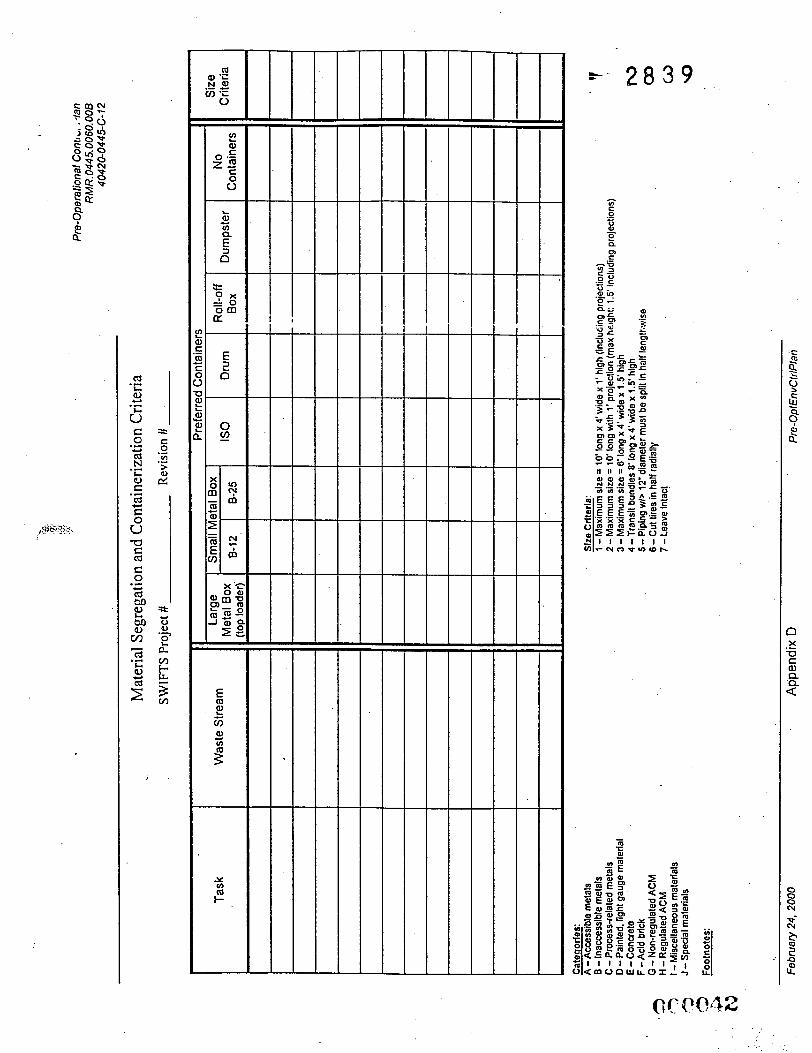
FDF will provide the appropriate waste containers for the various waste categories identified in the Waste Management Plan. RMRS will use the Material Segregation and Containerization (MSCC) form, Attachment D, to identify categories of waste and as their basis for containerization activities. These containers will include, but are not limited to, the following:
0 Large metal boxes 0 IS0 containers 0 Small metal boxes
February 25,2000 Page 16 of 18 Pre-OptEnvCtrlPlan
. . i .
Pre-Operational Control Plan RMR.0445.0060. OOE
1 2 3 4 5 6 7 8 9 10 11 12 13 14 15 16 17 18 19 20 21 22
2< : %;.23 !4
25 26 27 28 29 30 31 32 33 34 35 36
40420-0445612
55-gallon drums with lids Roll-off boxes Dumpsters.
Waste containers staged inside the Controlled Area will be lockable and will be kept locked unless authorized loading is taking place. FDF Radiological Control will be present to survey waste prior to authorized loading operations. Unfilled waste containers will be secured when no loading is in progress to prevent the addition of unknown materials. FDF will provide and maintain the lock and key to clean waste containers.
RMRS will notifivr FDF at least two (2) working days prior to needing waste containers. FDF will deliver erqty contakers a d pdlets t-3 i;i; ?MR2 cor5zsr stiig+g are.. F2F will dispose of full containers placed in this area by RMRS.
Designated RMRS personnel will be responsible for supervising container operations, including inspection of empty containers on receipt and waste loading activities. They will have the responsibility to ensure that containers, boxes and drums are filled such that the interior volume is as efficiently and compactly loaded as practical either up to the maximum gross weight limit of that container or until full by volume.
Containers will be checked for free liquid prior to loading. Ice is considered a free liquid. Containers will be weather protected, particularly when the lid is not secured, to prevent entry of snow and rain.
Clean construction waste will be surveyed and loaded into dumpsters provided by RMRS or its subcontractors on a daily basis to prevent an excessive amount of material from piling up near the container staging area. These dumpsters will remain locked when no loading is taking place.
FDF will visibly inspect full containers prior to final securing of their lids and container disposition.
RMRS will follow the requirements of FDF ACR-007, Waste Material Handling Criteria for Constrziction Projects, Rev. 2 (June 1998).
February 25, 2000 Page 17 of 18 Pre-OptEnvCtrfPlan
Pre-Operational Conttvl Plan RMR.0445.006O.OOB
4O42O.0445-C-12
I 5.0
3 1. 2
4
5
6 2. 7
8
9 3.
11 4. 10
12 13
14 5. 15
16 6. 17
18
19 7. 20
21
22 8.
24 9.
. - '3
25
26 10. 27
28
29
REFERENCES s- 2 8 3 9 FDF, Stormwater Pollution Prevention Plan, PL-3088, Rev. 0, Fernald Environmental Management Project, Fernald, OH (October 1999).
Ohio Environmental Protection Agency, Chapter 3745-1 7-08 of the Ohio Administrative Code, Restriction of Emission of Fugitive Dust, (July 1997).
RMRS, TS-02900, Technical Specification, Seeding (December 1998).
FDF, W ~ ! P Material Handling Criteria for Construction Projects, ACR-007, Rev. 2 Fernald Environmentai ivlanagement Project, Femaici, OH (:me 1 Y%).
FDF, Fugitive Dust Control Requirements, RM-0047, Rev. 0 (August 1997).
40 CFR Part 60 Appendix A, Method 22, Visual Determination of Fugitive Emission for Material Sources and Smoke Emissions for Flares
ACR-002, FDF Administrative Contractor Requirements, Contract Safe Work Plan Format Requirements, Rev. 2 (November 1994).
Fernald Silo 3 Project, Site Preparation Package, RMR-0445-0058 (February 2000).
FDF RP-0009, Radiological Requirements for the Release of Materials at the FEMP.
RMRS Technical Specification, 02485, Soil Erosion and Sedimentation Control.
~ ~~
February 25.2000 Page 18 of 18 Pre-OptEnvCtrlPlan
Pre-Operational Control Plan RMR. 0445.0060.008
4042O-0445C12
Appendix A
=- 2 8 3 9
Erosion and Stormwater Control Features Details
. .
Febmafy 25,2000 Appendix A Pre-OptEnvCtrfHan
. Pre-Operational Control Plan RMR 0445.0060.008
404209445.G12
3 - 5 % 5 - 8 %
8 - 20%
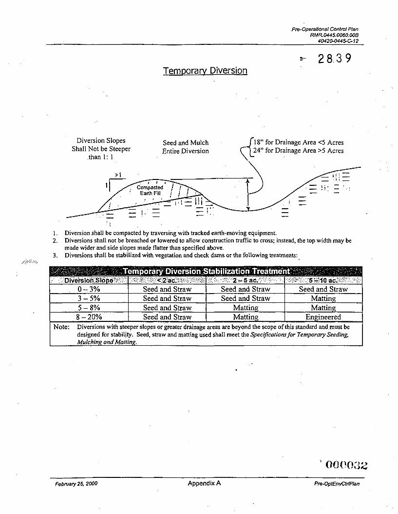
r- 28.3 9 Temporarv Diversion
Seed and Straw Seed and Straw Matting Seed and Straw Matting Matting Seed and Straw Matting Engineered
18” for Drainage Area <5 Acres 24” for Drainage Area >5 Acres
Diversion Slopes Seed and Mulch Entire Diversion Shall Not be Steeper
than 1: 1
. _
1. 2.
3.
Diversion shall be compacted by traversing with tracked earth-moving equipment. Diversions shall not be breached or lowered to allow construction traffic to cross; instead, the top width may be made wider and side slopes made flatter than specified above. Diversions shall be stabilized with vegetation and check dams or the following treatments:
,,!+<!. :.:>>
~~ ~
~ 0-3% I Seed and Straw 7 Seed and Straw I Seed and S t r a w 1
February 25,2000 Appendix A Pre-OptEnvCtdPlan
pre-Operational Control Plan RMR O445.0060.008
404204445C72
+- 2 8 3 9 Silt Fence
k- 10"Maximum 4
Trench to be Backfilled and Compacted
Febnrary 25,2000 ~~~ ~
Appendix A Pre-OptEnvCtdPlan
Pre-Operational Control Plan RMR.0445.0060.008
4042O-0446612
1
* 2 8 3 9
65 ft. 30 ft. 20 ft. 15 ft.
Specifications for
Check Dam
2 130 ft. 65 ft. 40 ft. 30 ft. -
Low Center Section - Must Cause Flow Over,
Not Around, Check
4" - 8" Rock
Cross Section Profile
1.
2.
3. 4.
The check dam shall be constructed of 4-8 inch diameter stone, placed so that it completely covers the width of the channel. The top of the check dam shall be constructed so that the center is approximately 6 inches lower than the outer edges, so water will flow across the center and not around the ends. The maximum height of the check dam at the center of the weir shall not exceed three feet. Spacing between dams shall be as shown in the plans or by the following table:
-.,'\,. y-,
Appendix A Pre-OptEnvCtrlPlan
Pre-Operational Control Plan RMR. 0445.0060.00B
4 O 4 2 W ~ - 12
Appendix B
Control of Fugitive Emissions Daily Records
t-- 2 8 3 9
February 25.2000 Appendix B Pre-Opt€nvCtrfP/an
2 8 3 9 I s b
Pre-Operational Control Plan RMR. 0445.0060.008
40420-0445C12
. * =- . 2 8 3 9 C ' ' . -
Appendix C
RMRS Off-Hour Dust Control Procedure
February 25,2000 Appendix C Pre-OptEnvCfdPan
Pre-operational Control Plan RMR.0445.0060.008
4042GO445C12
RMRS +- 2 8 3 9
RMRS OFF-HOUR DUST CONTROL PROCEDURE ISNSilo 3 Construction
1. RMRS personnel or their subcontractors with responsibilities for the Off-Hour Dust Control Coverage will retain a copy of the Off-Hour Dust Alert Schedule and a RMRS Employee Contact Sheet, both at the FDF Site Office and in their vehicle or home, i.e., the schedule and contact sheet should be readily available at all reasonable times.
2. RkdRS personnel or their subcontractors working on Silo 3 F'icjCCt construction activities are responsible for being aware of their duties and responsibilities regarding Off-Hour Dust Control.
3. If a scheduling conflict arises, personal or otherwise, the affected person is responsible for making the required revisions to the Off-Hour Dust Alert Schedule to ensure adequate personnel coverage is maintained at all times. The responsible person within RMRS or his designee must approve all revisions to this schedule. A copy of the modified schedule must be distributed to all affected RMRS and FDF personnel no later than the Thursday before the affected week in the schedule.
,+w I*
4. Each week, RMRS will designate one person as the qualified water wagon operator and one person as the sprinkler system operator. The RMRS Designated Primary Contact (DPC) ant the designated operators must be hlly trained and medically cleared to operate in a Controlled Area.
5. When RMRS is notified by FDF that Off-Hour Dust Control is required, the RMRS DPC or his equivalent will contact the designated operators and coordinate the implementation of this dust control procedure, as detailed in approved Fugitive Dust Control Plan.
6. If either of the designated operators have not responded within 15 minutes of initial attempts to contact them, alternative operators will be contacted until available operators can be found. These operators must also be fully trained and medically cleared to operate in a Controlled Area.
7. It is the responsibility of the RMRS DPC to keep the designated FDF Management Contact informed of all efforts to contact operators and to give details concerning their estimated arrival times at the Silo 3 Project site.
8. Once on-site, the RMRS DPC and operators, together with the designated FDF contact will implement the Emergency Dust Control measures including, but not necessarily limited to, the preparation of a Safe Work Plan and the Fugitive Dust Control Plan.
I
Febnrary25.2000 . Appendix C Pre-OptEnvCMPlan
Pre-Operational Control Plan RMR. 0445.0060. OOB
404204446612
=- 2 8 3 9 9. The RMRS DPC is responsible for documenting RMRS’ efforts, including contacts and
response times and communication the same to FDF and RMRS’ Silo 3 Project Management. The Off-Hour Dust Alert Work Order must be filled out by RMRS and countersigned by the designated FDF representative prior to RMRS leaving the Silo 3 Project site. Note: Off- Hours Dust Control is an additive unit pay item to the RMRS Silo 3 Project contract and must be properly documents for payment.
&bNaIy 25.2000 Appendix C Pre-OptEnvCtrlPlan
Pre-Operational Control Plan RMR. 0445.0060.008
40420-0445612
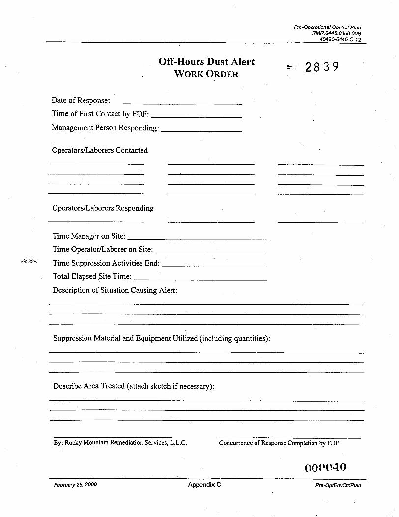
Off-Hours Dust Alert WORK ORDER k-- 2 8 3 9
Date of Response:
Time of First Contact by FDF:
Management Person Responding:
OperatorsLaborers Contacted
OperatorsLaborers Responding
Time Manager on Site:
Time OperatorLaborer on Site:
Time Suppression Activities End:
Total Elapsed Site Time:
Description of Situation Causing Alert:
,<!;<:<ybL
~~
Suppression Material and Equipment Utilized (including quantities):
Describe Area Treated (attach sketch if necessary):
By: Rocky Mountain Remediation Services, L.L.C. Concurrence of Response Completion by FDF
Febntary 25,2000 Appendix C Pre-OptEnvCttiPlan
Pre-Operational Contm/ Plan RMR.0445.0060.00B
4O42O-04454-12
5 - 2 8 3 9
Appendix D
Material Segregation and Containerization Criteria
February 25,2000 Appendix D Pre-Op EnvCtrlPlan
m k
E 2 Q
nrr h- 2 8 3 9
Pre-Operational Control Plan RMR.0445.0060. OOB
40420-044561 2
e- 2 8 3 9
Appendix E
Estimated Amounts of Each Type of Waste Stream
000043
February 24,2000 Appendix E Pre-OptEnvCtrlPlan
Pre-Operational Control Plan RMR. 0445.0060.00B
40420-0445-C-12
I
+- 2 8 3 9 Table 4.1
ESTIMATE OF WASTE DURING CONSTRUCTION
February 24,2000 Appendix E Pre-OptEnvCtrfPkin
*- 2 8 3 9 . . . . .
__ . .. . -
RMRS . ? - 2 8 3 9 - --. Rocky Mountain Remediation Services, LLC ... pml*cUn#U~e *mPonmmi
4 2 2
-
1 2 3 4 5 6 7 8 9
10 11 12 13
14
15
ATTACHMENT B
Site Preparation Package Design Drawings
February 25,2000 Attachments General Descdption of the Work
ZOOE-2s p O m C l
N 481000
NEW LAYDOW ACCESS APPROACH -
(GRAVEL)
NEW DIESEL STORAGE TANK
N 480800 NEW EQUIPMENT
NEW OPERATIONS/
FENClNG ACCESS CONTROL -
N 480600
'4 480400
\ --.
\ \ \
NEW TREATMENT FACILITY DRIM APPROACH (CONCRETE)
UmmalNEnl-~ c
REFERENCE DRAWINGS STATE OF OHIO N O R M
(NAD 83) DRAWING NO. TITLE 6 52-yx)l QHERALNOTES-CIVIL s- 2 8 3 9 , L -
*.I
HYDRANT AN0 WATER HYDR
1 '=50'
0 0
r\ * ro
'2 W
'47
BU-11 - N 480149.27. E 1317017.97. ELEV. 569.91 n. BU-12 - N 480389.05, E lS47841.98, W. 578.70 FT.
3. RMSON awDs ARE UARKED SHOWC THE REVISON NUUBER m WHICH CHANCES ARE YADE.
BOT FOR CONSTRUCTIONl -------A
FDF - FEMP
CIVIL SITE PLAN
I- I _ - I _ -
b - 2 8 3 9
STORM SEWER PLAN
.-
I 2. CULVERT INLET AREAS ARE TO BE RECWXo TO ENHANCE RUNOFF couEcnoN. ROAD 3. CULVERT ORNNS OlsCnARCE TO THE NORTH, WEST OF THEN THE NRMNC INFRAsTRUCNRE WEST.
DRAINS CULVERT TO OISCHARCE M E NORTH. EAST THEN OF NRNlNC THE mmrSmucwRE EAST. ROM)
STORM SEWER PLAN AND PROFILE
-..
- .
GRADING AND DRAINAGE PLAN
STATE OF OHIO NORTH (NAD 8s)
SCALE FEE1
1 '=50'
2. SURFACE RUNCFF FROM THE INFRASTRUCTURE ROAD A WD STREET W U DRAIN TO THE I S PAD. WHERE IT BE COUEC" BY THE PROPOSED CATCH BASINS. I S. MAL GRADE SLOPES WTHlN THE I S AREA VARY IN ORDER TO MATCH WSnNC ELEVAllWS AND TO F A ~ U T A ~ DRNNACE FLOWS. I
GRAOINGANO DRAINAGE PLAN
REFERENCE DRAWINGS
8 3 9 I I
NOTES
1. AGGREGATE BASE COURSE SHAU CONFORM TO OHIO DEPARTMWT OF TRANSPORTATION, OOOT. ITW 304.
2. kOlEXTILE FABRIC SHAU CONFORM TO OOOT ITW 712.09, TYPE E.
3. SUBCRADE SHAU BE EXCAVATE0 A MINIMUM OF 95% 6' MOOIFIED AND ME SURFACE PROCTOR. COMPACTED TO
I
ISA SLAB PLAN (REFER TO DWC. 52-3004 FOR TOP OF SLAB ELEVATIONS)
N 480668.44 "I" ~
E 1347193.18 480675*86 q E 1347222.66 f-1 I S A SLAB HORIZONTAL CONTROL PLAN
VECETATIVE CDKR 7 CONCRE TE EXISTING ASPHALT
PAVED ROADWAY p ROADWAY 3. ASPHALT P A W
#4's OR WWR FINISHfD GRADE STORACE AREA
- &MPACTED SUBGRADE (PIP.)
I I l l HEAVY CAPACITY CRATE W/ CAPACITY TO CARRY DUAL VMEELED PNEUMATIC TIRES HAVING 120 P S I CONTACT PRESSURE AND 236 SO. IN. CONTACT AREA PER TIRE. TIRE SPACING PER PAIR IS
7 F I N E 1
BASE COURSE (W.) (Sff NOTE 3)
CONCRETE 18 1/2' c/c. PAVEMENT 1
SILO 3 PROJECT FDF - FEMP
ISA-PAVEMENT PLAN & SECTIONS
REFER TO TIP. WANSION JOINT SEALANT DETAIL ON r TWF C! FXPANSIOEI JOINT Typ. S E C T I O N a / ON . . . DRAWING - - - - . -. 52-3014 - - -. . - -
f4's OR WW 7 / 7 t - 2 ' CLR. (".)\' I
I - ..' *. .. COMPACTED B A C K F I U l - .--I . ..
I YJUbKAW
CONCRETE 1- (SEE SPECIFICATIONS)
.(Br-DlluM 4
14's OR m
BAR 0 24' ac
TYPE CONTRACTION JOINT NOT TO SCALE
1 r-0. -J 2.4- .
I
THICKENED SLAB EDGE DETAIL NOT TO SCALE
3/4* OIA 15. LONG J %CUM GREASED TIE BAR 8 24. O.C.
SECTION AT RICHHI
OEPTH AS RECOCMNMD BY UANUFACTVRER OF
WHERE NEW SLAB ADJOINS EXIST IN SLAB. PRE-DRIU HOGS AND
TRUCTION JOINT EPOXY SOLID DOWELS
- TYPE @ LONGITUDINAL AND TRANSVERSE
CONSTRUCTION JOINT WITH TIE BARS NOT TO SCALE
DOWEL BAR- 3/4' DIA.. 15' LONG, '*' OX* PREMOLDED
NON-EXTRUD ING COMPRESSIBLE JOINT FILLER
EXPANSION CAP LL GREASE PAINTED END OF DOWEL
PREMWIED NOTE: JOINT MATERIAL
W A L L BE NON-EXTRUDING TYPE. CONFORM INC TO AAWTO SPEC. M-90 OR M-153
TYPE 0 EXPANSION JOINT NOT TO SCALE
REFERENCE DRAWINGS - n u . OAAWIHGNO. I
52-3013 I ISA PAIEMENT PLAN AND SECTIONS I n NOTES
1. 'ALL BE 4000 CAST-IN-PLACE PSI. CCNCRElE SHALL
=-- 2 8 3 9
LEGEND WWR - WELOEO WIRE REINFORCING
FOF - FEMP ISA
. PAVEMENT DETAILS
M o w i l s o N K M I D G E N ~ m Id(m V. aha. Ulllttm CO MI27 T d (XS) oHI-(QR @
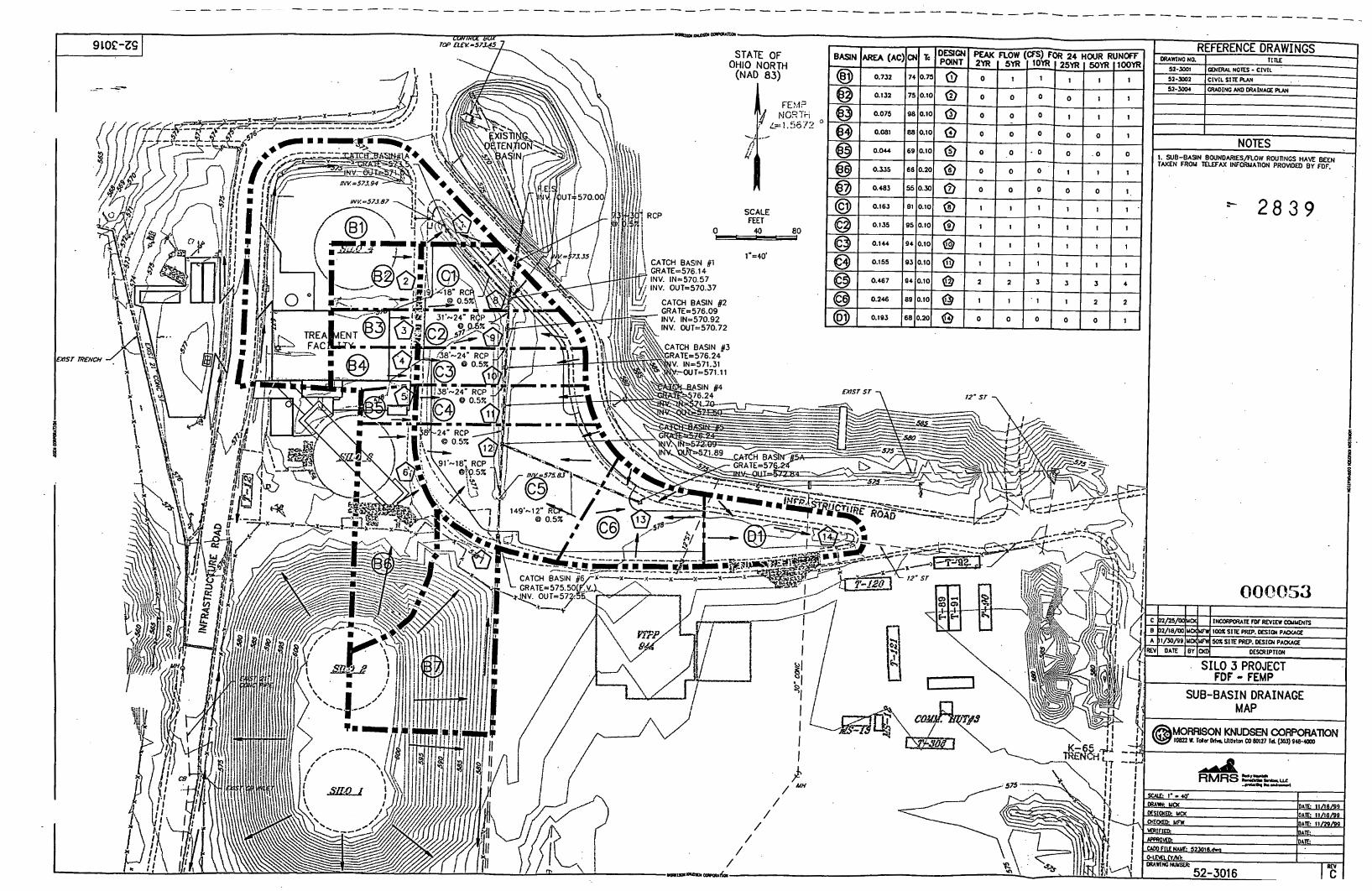
- - - - _ - - --------- - _ _ _ _ _ - - - _ _ _ _ _ - - - - _ - - - - - - - - - - - _ _ _ - - _ _ - - - - - - - - _ _ - - - -
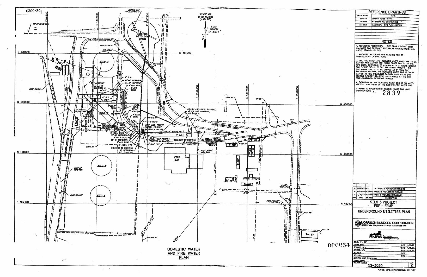
I i- i: r U I I U
POMESTIC WATER AND FlRF WATFR
F I
I
I /
/ /
/ /
eLAN
/ /
/ /
INTERSECnWS 2. PROWDED WATERUNE (IF PIPE R U N S PIPE LENGTHS ARE TO
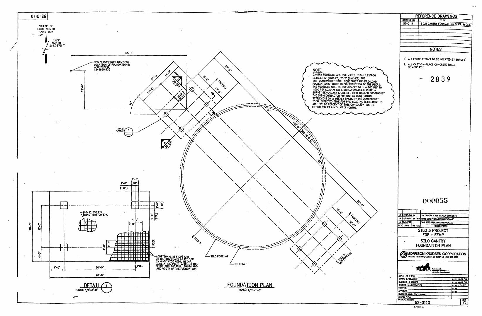
. .
0 1 LE-ZG
-.. -..
FOUNDATION PLAN
REFERENCE DRAWINGS F
TIRE ORAWIMi K1 52-5111
1
SILO GANTRY FOUNDATION SECT. & DET.
-
NOES
1. ALL FOUNDATIONS TO BE LOCATED BY SURVEY.
CAST-IN-PLACE CONCRETE SHAU 4000 PSI.
2 8 3 9
FDF - FEMP-. SILO GANTRY
FOUNDATION PLAN
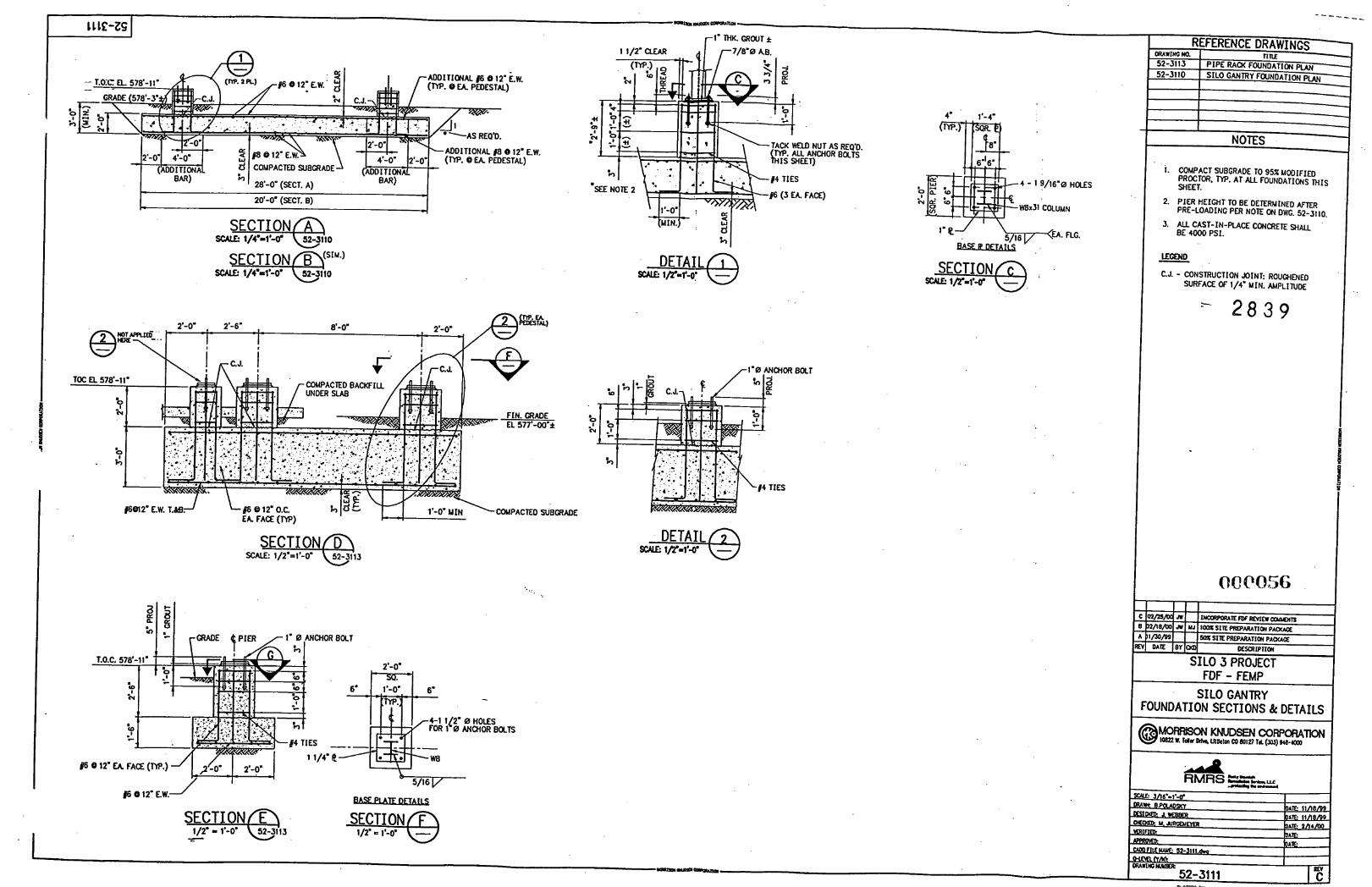
-------
(SIM.) SECTION B SCALE: --e 1/4*d-D' 524110
COUPACTED !3hGRADE
SECTION D SCALE: --e 1/2'=1'-0" 52-3113
ps 8 12' Eh
0 HOLES ANCHOR BOLTS
r l ' 0 ANcncf7
4. *'-A=
0 cy .'
. 4 - 1 9/16'0 HOLES
~ 8 x 3 1 COLUMN
BOLT
1. COMPACT SUBGRAOE TO 952 MOOIFIED
PROCTOR. SHEET. Typ. AT ALL FOUNDATIONS MIS
2. PIER HEIGHT TO BE DETERMINED AFTER PRE-LOADING PER NOTE ON DWG. 52-3110.
BE 4000 PSI. 3. ALL CAST-IN-PUCE CONCRETE S H A U
L E W D
C.J. - CONSTRUCTION JOINT: ROUCHENED SURFACE OF 1/4' MIN. AMPLITUDE
-
SILO GANTRY FOUNDATION SECTIONS & DETAILS
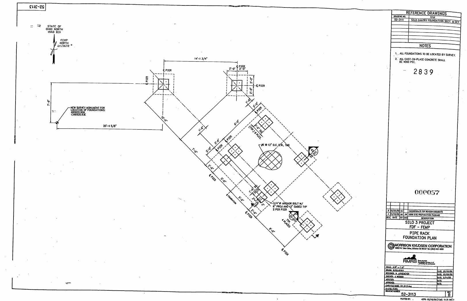
_ - - - STATE OF OHIO NORTH
<NAD 83)
I
I . FEHP
I
1.. ALL FOUNDATIONS TO BE LOCATED BY SURM~.
2. BE ALL 4000 CAST-IN-PLACE PSI. CONCRETE S n A U
0000.57
FDF - FEMP PIPE RACK
FOUNDATION PIAN
MoRwsoNKNuDsENcoRpoRAm GB lm L Tar% U L h W 80127 ld (3W) OCa-Cm,
L
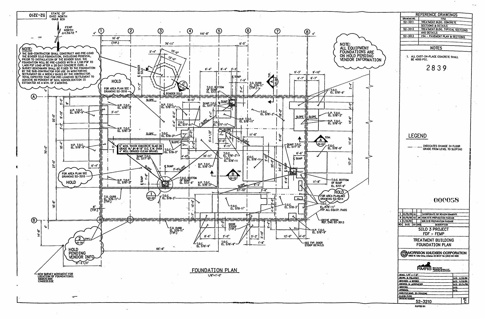
- _
STATE OF --- LRAWINO rm TIU
SECTIONS TREATMENT k BLDC. DErAILS TYPICAL . SECTIONS AND DETAILS 1% - PAVEMENT PLAN k SECTIONS
01zc-ZsI OHIO NORTH
52-3211 TREATMENT BLDC. CONCRETE
52-3212
52-3013
<NAD 83) -
NOTES
@-
I
I
"ri' T
1346920.9X
FOUNDATION PLAN 1/8'=1'-0'
1. ALL CAST-IN-PLACE CONCRETE SHU BE 4000 PSI.
2 8 3 9 .
LEGEND
,..,INDICAESWANGE INFLOOR CRADE FROM LEVEL TO SLOPING
I 1 I
TREATMENT BUILDING FOUNDATION PLAN
1. h UUeh 03 MI27 Id (303) W0-W
I I
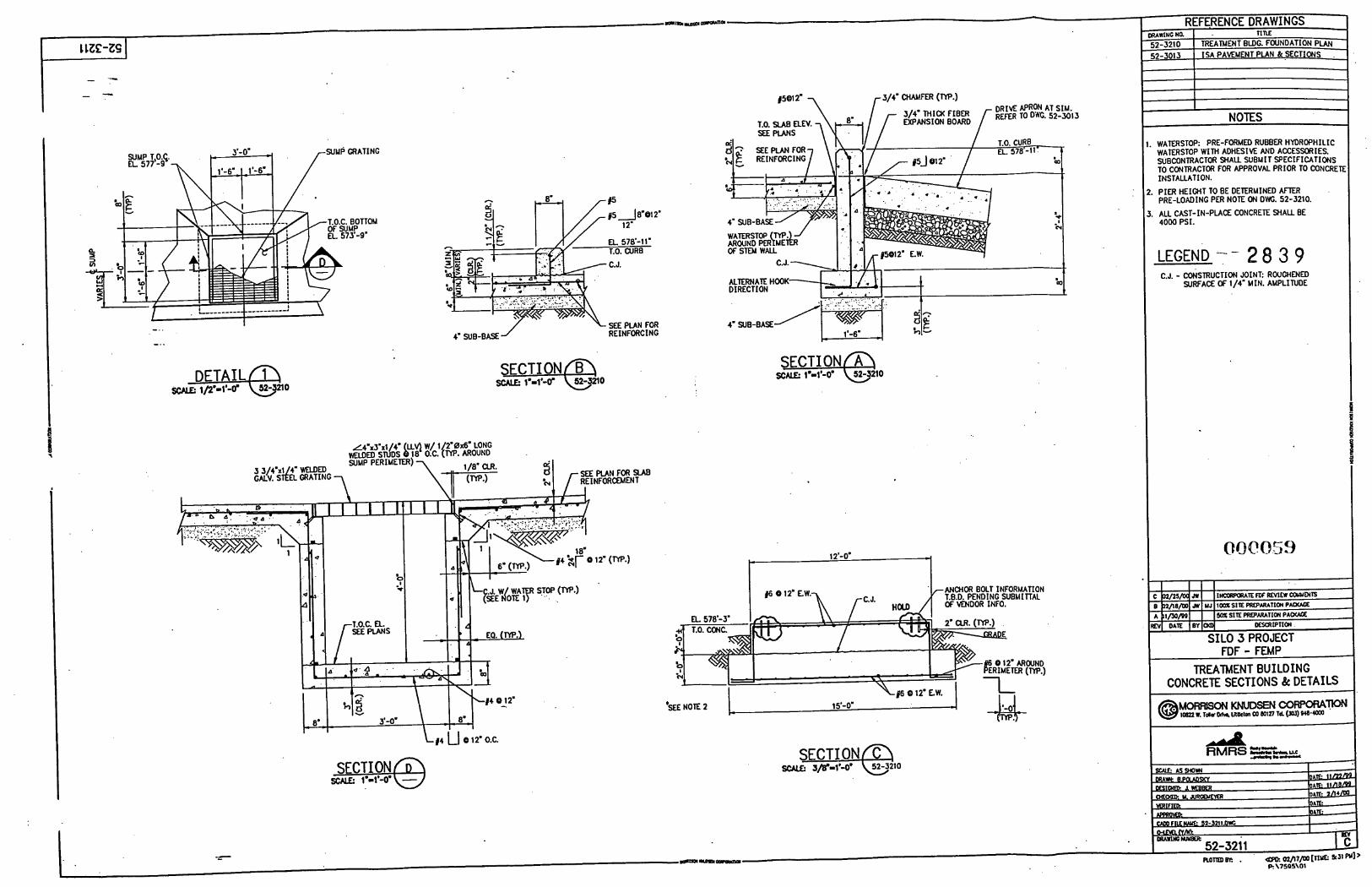
4' SUB-BASE ./ SEE PLAN FOR REINFORCING
SECTION^ SCALE lo=l'-V 52-5210
L # 4 u 0 12' O.C.
12'-0'
ANCHOR T.B.D. PENDING BOLT INFORMATION SUBMITTAL
OF VENDOR INFO.
REFERENCE DRAWINGS LAWINC NQ TITLE
12-3210 TREATMENT BLDG. FOUNDATION PLAN 12-3013 ISA PAVEMENT PLAN &-SECTIONS .
4 NOTES
WATERSTOP. PRE-FORMED RUBBER HYDROPHILIC WATERSTOP W I T H ADHESIM AND ACCESSORIES. SUBCONTRACTOR SHAU SUBMIT SPECIFICATIONS TO CONTRACTOR FOR APPROVAL PRIOR TO CONCRETE
PIER HEIGHT TO BE DETERMINED AFTER
INSTALLATION.
PRE-LOADING PER NOTE ON DWC. 52-3210.
ALL CAST-IN-PLACE CONCRETE SHAU BE 4000 PSI.
LEGEND -- 2 8 3 9 C.J. - &STRUCTION JOINT: ROUGHENED
SURFACE OF 1/4' MIN. AMPLITUDE
FDF - FEMP TREATMENT BU I LD I N G
CONCRETE SECTIONS & DETAILS
M o F w l s o N K N u D s E N ~ ~ I- 1. Tole D I M U l U t t m CO Wt27 ld (Jar) 940-1ooO @
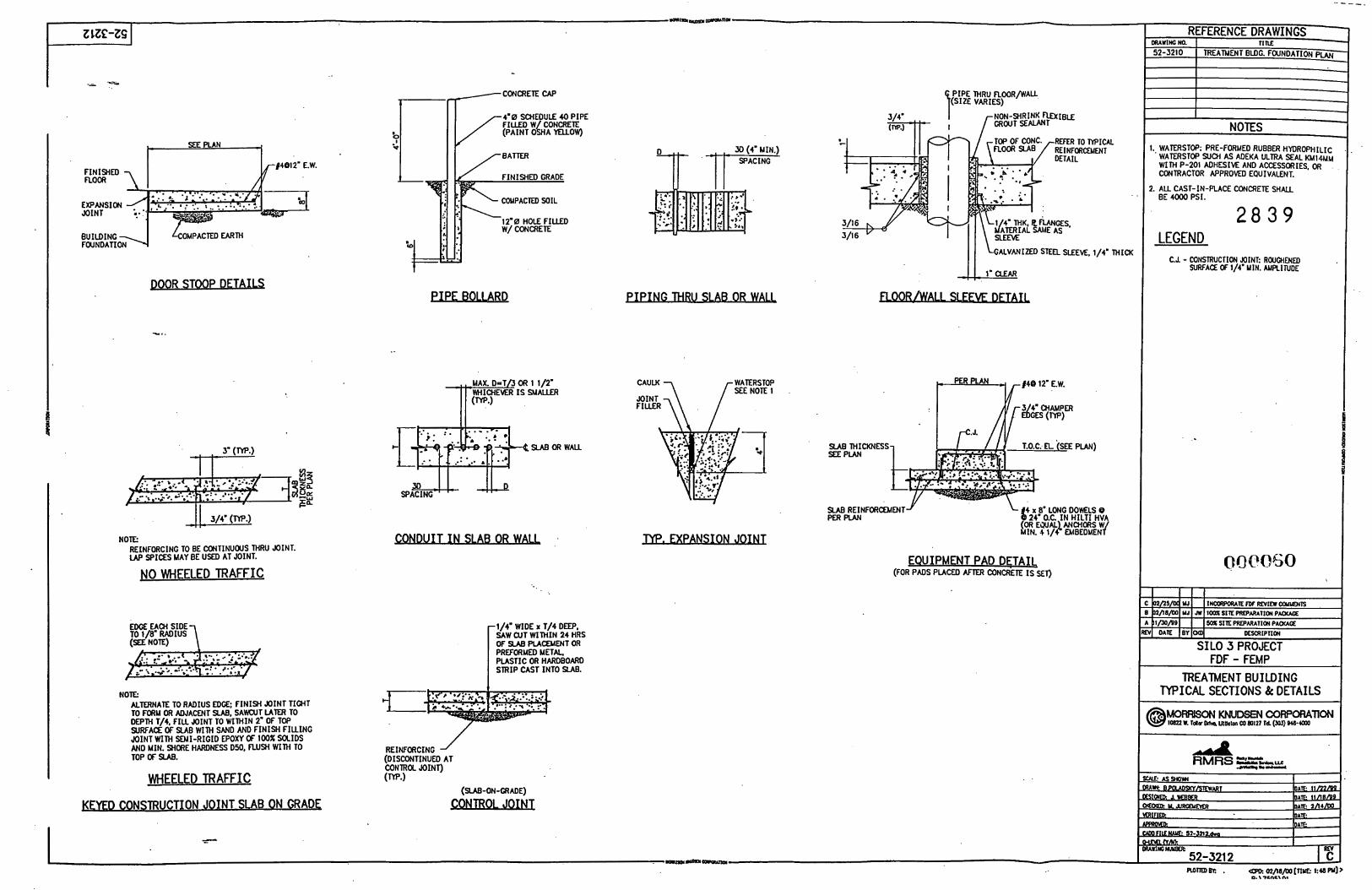
REFERENCE DRAWINGS T I RE D R A W i N G N a 52-3210 I I TREATMENT BLDC. FOUNDATION PLAN
I
PIPE THRU FLOOR/WAU (SIZE VARIES)
MOUT NON-SHRINK SEALANT ~ I B L E 4.0 SCHEDULE 40 PIPE FILLEDW CONCRETE (PAINT O L A YELLOW)
I
NOTES
t- SEE PLAN i 1. WATERSTOP: PRE-FORMED RUBBER HYDROPHILIC . WATERSTOP SUCH AS ADEKA ULTRA SEAL K M l W u WITH P-201 ADHESIVE AND ACCFSSORIFC M
DETAIL f4012' E.W. Ip -.._-___-..._-, ~,
CONTRACTOR APPROMD EQUIVALENT.
2. A U BE 4oDD CAST-IN-PLACE PSI. CONCRETE S H U
2 8 3 9 LEGEND
COUPACTED SOIL
12'0 HOLE FILLED w/ CONCRETE
EXPANSION N I N T
BUILDING 4 kOMPACN) EARTH FOUNDATION 1 1 LGMVANIZEO ma SLEEVE, 1/4' THICK IZEO m a SLEEVE, 1/4' THICK
C.J. - CONSTRUCTION JOINT: ROUGHEND SURFACE OF 1/4. UIN. AUPLITUDE
DOOR STOOP D E T U PIPE BOLLARD
7-p&Eii41ssMALLER MAX. D=T 3 OR 1 1/2' #4@ 12' E.W.
I rc.J* /I11 SLABORWALL
.. 3- (W.) - I i
SLAB REINFORCEMENTJ' PER PIAN
NOTE: REINFORCING TO BE CONTINUOUS THRU JOINT. LAP SPICES MAY BE USED AT JOINT. 000050 EQUIPMENT PAD DETAIt
(FOR PADS PLACED AFTER CONCRETE IS SET) BO WHEELED TRAFFIC 7
-1/4* WIDE x T/4 DEEP, U W CUT WITHIN 24 HRS OF SUB PUCEUENT OR PREFORMED METAL. PLASTIC OR HARDBOARD STRIP CAST INTO SLAB.
TREATMENT BUILDING TYPICAL SECTIONS & DETAILS NOTE:
ALTERNATE TO RADIUS EDGE: FINISH JOINT TIGHT TO F a U OR ADJACENT SLAB, S A W 1 LATER TO DEPTH T/4, FILL JOINT TO WITHIN 2' OF TOP SURFACE OF SIAB WITH SAND AND FINISH FILLING JOINT WITH SEMI-RIGID EPOXY (# 100% SOLIDS AND MIN. SHORE HARDNESS D50, FLUSH WITH TO TOP OF SLAB. 4
RMRS (DISCONTINUED AT CONTROL JOINT) (W.) WHEELED TRAFFIC
(SUB-ON-GRADE)
)(EYED CONSTRUCTION JOINT SLAB ON GRADE
I . .QIoI..opl(aaMp
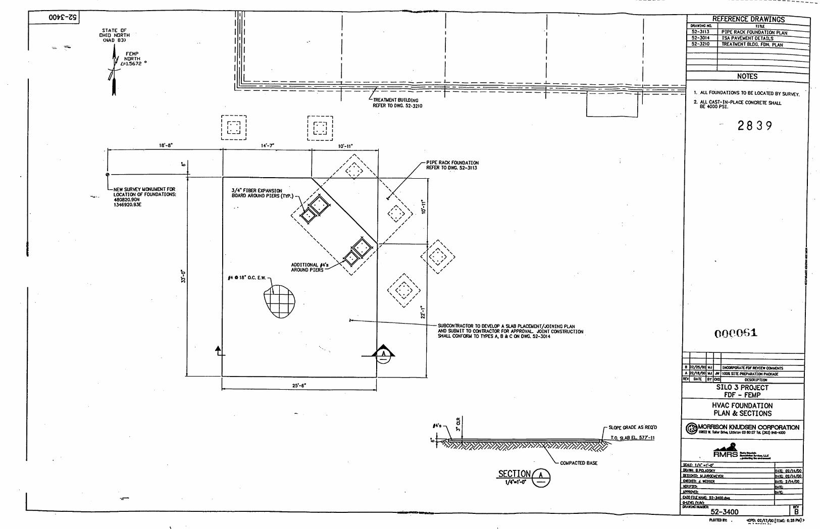
- -_____- - - - - - - - -_____
I - I
OOPE-2s STATE OF
; I l l ; 1
I I I I I..." "S.
I I I
iI!i Illll I I I I
, _...#"#L
NOTES
1. ALL FOUNDATIONS TO BE LOCATED BY SURVEY.
2. ALL CAST-IN-PLACE CONCRETE SHALL BE 4000 PSI.
I I I REFER TO DWG. 52-3210
I
r----1 r---- 1
- 2 8 3 9 18'-8'
t .
I (D
NEW SURVEY MONUMENT FOR
480820.9ON 1346920.93E
-*.. . LOCATION OF FOUNDATIONS
PIPE RACK FOUNDATION REFER TO DWC. 52-3113
3/4' FIBER EXPANSION BOARD ARWND PIERS (PIP.)
_.
\
\
\ /
/ /
/ /
/ A-
/ \ /c\ \\ - . <; . ;> /' \ " // \ / v . 5
c
-SUBCONTRACTOR TO DEVELOP A SLAB PtACfMENT/JOINING P U N AND SUBMIT TO CONTRACTOR FOR APPROVAL. JOINT CONSTRUCTION SHALL CONFORIA TO TYPES A. B k C ON DW. 52-301 4
4 t 1
SILO 3 PROJECT FDF - FEMP
HVAC FOUNDATION PLAN & SECTIONS
A RMRS
COMPACTED BASE
~7mF-g@ SECTION
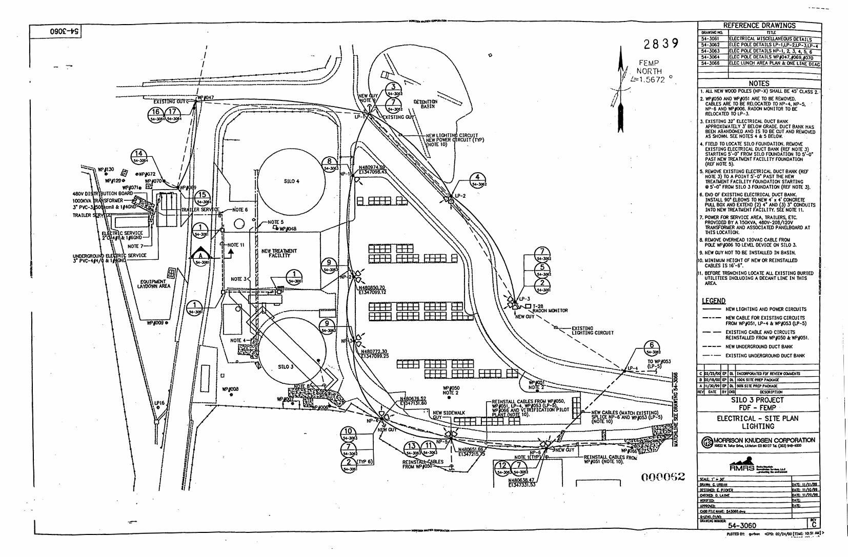
1
I
0
cy16
I 2 8 3 9
-----
I
I NOTES
1. ALL NEW Woo0 POLES (NP-X) SHALL BE 45' CLASS 2.: 2. WflSO AND W@51 ARE TO BE REMOMD.
CABLES ARE TO BE RELOCATED TO NP-4, NP-5, RELOCATED NP-6 AND Wf006. TO LP-3. RADON MONITOR TO BE
APPROXIMATELY 3' BELOW GRADE. DUCT BANK HAS AS BEEN SHOWN. ABANDONED SEE NOTES AN0 4 I S k TO 5 BELOW. BE CUT AND REMOMD
3. EXISTING 32' ELECTRICAL DUCT BANK
I. F I N ) TO LOCATE SILO FOUNDATION. REMOM EXISTING ELECTRICAL DUCT BANK (REF NOTE 3)
PAST NEW TREATMENT FACIL IM FOUNDATION (REF NOTE 5).
STARTING 5'-0' FROM SILO FOUNDATION TO 5'-0'
i. REMOM EXISTING ELECTRICAL DUCT BANK (REF NOTE 3) TO A POINT 5'-0' PAST THE NEW TREATMENT FACILITY FOUNOATION STARTING @ 5'-0' FROM SILO 3 FOUNDATION (REF NOTE 3 - - I .
. END OF EXISTING ELECTRICAL DUCT BANK. INSTALL 90. ELBOWS TO NEW 4' x 4' CONCRETE PULL BOX AND EXTEND (2) 4' AND (3) 3' CONDUIT! INTO NEW TREATMENT FACILIM. SEE NOTE 11.
, P O W ? FDR SERVICE AREA, TRAILERS, ETC. PROVIDED BY A j5DKVA. 480V-208/12OV M I S TRANSFORMER LOCATION. AND ASSOCIATED . PANELBOARD AT
REMOM OVERHEAD l2OVAC CABLE FROM POLE WpoO6 TO LEML DEVICE ON SILO 3. NEW GUY NOT TO BE INSTALLED I N BASIN. CABLES MINIMUM I S HEIGHT 16'"''. OF NEW OR REINSTALLED
BEFORE TRENCHING LOCATE ALL EXISTING BURIED UTILITIES INCLUDING A DECANT LINE I N M I S AREA.
KzEi!u2 NEW LIGHTING AND POWR CIRCUITS
NEW CABLE FOR EXISTING CIRCUITS FROM W/roSl, LP-4 & WN53 (LP-5)
EXISTING CABLE AND CIRWITS
- ---- -- REINSTALLED FROM WyOW & WryOSl.
.--- NEW UNDERGROUND DUCT BANK
-_- EXISTING UNDERGROUND DUCT BANK
I l l
FDF - FEMP ELECTRICAL - SITE PLAN
L I GH T I NG
1 2 8 3 9 Rocky Mountain Remediation Services, L L C - RMRS . . . pmfecUng pn mvhnmmt
! l 2 3 ' 4 5 6 7 8 9
10 11 12 13 14
15
I
ATTACHMENT C
Site Preparation Package Technical Specs
c
Y
.
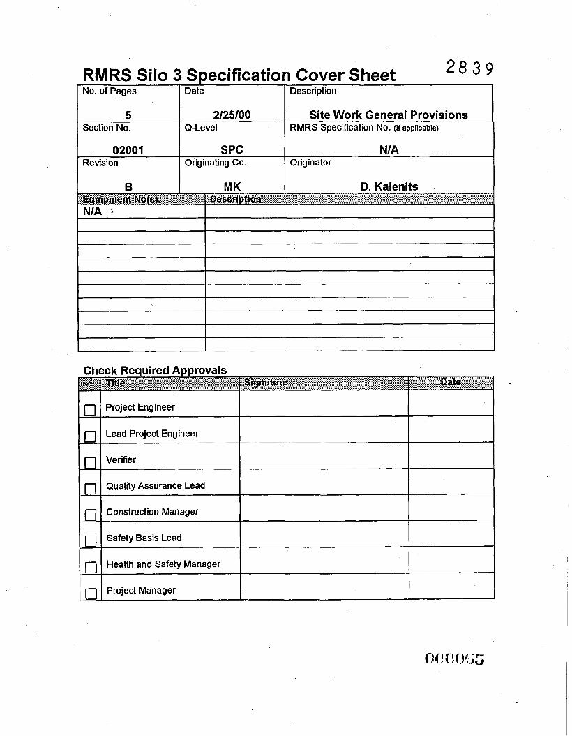
No. of Pages Date
5 2/25/00 Section No. Q-Level
Description
Site Work General Provisions RMRS Specification No. (If applicable)
Project Engineer
Lead Project Engineer
Verifier
Quality Assurance Lead
Construction Manager
Safety Basis Lead
Health and Safety Manager I
02001 Revision
1 Project Manager I I I
SPC N/A Originating Co. Originator
Site Work General Provisions Spec. Section: 02001
Revision: B Rocky Mountain Remediation Services, LLC. RMRS . . . pmbethg Ih. mnvhnmmt
L
2 8 3.9
SECTION 02001
SITE WORK GENERAL PROVISIONS
TABLE OF CONTENTS
PART 1 GENERAL ................................................................................................................. 1 1.1 SECTION INCLUDES ...... . .. .. . . . .... . . . . . . .. . . . . . . . . . . . . . . .. . . . . . . ... . . . . . . . . . :. . . . . . . .. ... . . . . . . . ... ...... . .. . . . . . . 1 1.2 SITE PROCEDURES .................................................................................................... 1 1.3 REFERJZNCES .............................................................................................................. 1 1.4 ACCURACY OF DATA. .. . . .. . . . . . .. . . . . . . . . . . .. . . . . . . . . . . . . . . . . . . . . . .. . . . . . . . . . . . .. . . . . . . . . . . . . . . . . . . . . . . . . . . . . .. . . .. 2 1.5 EXISTING UTILITY PROPERTIES AND SERVICE ................................................... 1.6 EXISTING IMPROVEMENTS ....... . . . . . . . . . . . . . . , . . . ... . . . . . . .. . . . . . . . . . . . . . . . . . . . . .. . . ... . . . . . . . . . . . . . . .. . . . . . . 3 1.7 INSPECTION AND TESTS ... . . . . . . . . . . . . . . . . . . . . . . . . . . . . . . . . . . . . . . . . . . . . . . . . . . . . . . . . . . . . . . . . . . . . . . . . . . . . . . . . . . . . . . .3 1.8 UNFAVORABLE WEATHER CONDITIONS.. . . . . . . . . . . . . . . . . . . . . . . . . . . . . . . . . . . . . . . . . . . . . . . -. . . . . . . . . . . .3
PART 2 PRODUCTS ............... ........................ ..... .. ... ....... ..... ................ ................................. . 3 NOT USED ............ ........... ................................ ... ..................... .. . .. .................. . ........... .... ....... 3
4 PART 3 EXECUTION ............................................................................................................. NOT USED ............................................ .......... ...... .......... ........ ........................................ ....... 4
February 25,2000 i RMRZS Site Work General Provisions
Site Work General Provisions Spec. Section: 02001
Revision: B Rocky Mountain Remediation Services, L L C . ... p m ~ l l n g l h ~ ~ r n h n r * n l
_. RMRS
2 8 3 9 SECTION 02001
SITE WORK GENERAL PROVISIONS
PART1 GENERAL
1.1 SECTION INCLUDES
A. The general provisions for site w rk specified herein are a part of all other Sections under division 2 and the Contract for this Work and apply to each of these Sections.
1.2 SITE PROCEDURES
RMRS L.L.C. (“the Contractor”) will obtain the site permits required to perform work at the Fernald Environmental Management Project (FEMP). Terms, conditions, and requirements for performing work at the FEW site are detailed in the Subcontractor’s Statement of Work.
All reports, certifications, test and inspection results, and other documentation required by specification or contract shall be submitted to RMRS Management.
.The Subcontractor shall not@ RMRS site management of changes to conditions or requirements that hinder or prevent the completion of the Subcontractor’s scope of work. All communication with FEW site management shall be made through RMRS.
1.3 REFERENCES
A. All work and materials shall be in accordance with applicable State of Ohio and United States Environmental Protection Agency @PA) regulations, Department of Energy (DOE), Fernald Environmental Management Project (FEMP) Policies, as well as all other state and local laws and utility laws, rules, and regulations. Nothing in the Contract Documents shall be construed to permit work not conforming to the above.
B. If there is any conflict between the above referenced codes and standards and Drawings or Specifications, the codes and standards shall govern, except when the Specifications or Drawings call for material or construction of better quality than is
February 25,2000 1 of4 RMRS Site Work General Provisions
Site Work General Provisions Spec. Section: 02001
Rocky Mountain Revision: B Remediation Services, LLC. RMRS ... probcung Onamhnmmt
L
-- 2 8 3 9 required by the above codes and standards; then the provisions of Specifications or Drawings shall take precedence over the requirements of said codes and standards. The Subcontractor shall fiunish without extra charge any additional material and labor when required to comply with these codes and standards, even though the work is not mentioned in the Specifications or shown on the Drawings.
C. Additional Section References
RM-002 1, Safety Performance Requirements Manual
RM-0445-0021, Fernald Silo 3 Project-Specific Health and Safety Plan
RM-0445-0060, Fernald Silo 3 Project Pre-Operational Environmental Control Plan
RM-0445-0019, Fernald Silo 3 Project Quality Assurance Project Plan
1.4 ACCURACY OF DATA
A. Information obtained by the Contractor regarding site conditions, subsurface information, groundwater elevations, existing construction of site facilities, as applicable, and similar data will be available for inspection upon request.
B. Some obstructions may not be shown. Bidders are advised to carefully inspect the existing site before preparing their proposals. Removal and replacement of minor obstructions shall be anticipated and accomplished, even though not shown or specifically mentioned.
C. Site data given herein and on the Drawings are subject to the provisions of Contract General Conditions, an’d their absolute accuracy cannot be guaranteed. Exact locations, distances, elevations, and similar data shall be finally governed by field conditions and the directions of the Contractor.
D. The Subcontractor further acknowledges that they have satisfied themselves as to the character, quality, and quanti& of surface and subsurface materials to be encountered fiom their inspection of the site and fiom reviewing available records of exploratory work finished by the Contractor or included in these Documents. Failure by the Subcontractor to become knowledgeable with the physical conditions of the site and all the available information will not relieve the Subcontractor fiom responsibility for properly estimating the dficulty or cost of successhlly performing the work.
February 25,2000 2 of4 RA4RS Site Work General Provisions
0 10 P w; 8
Site Work General Provisions Spec. Section: 02001
Rocky Mountain Revision: B Remediatiin Services, LLC. . . . pmbcUng (h. *mlmnmml
- RMRS
1.5 EXISTING UTILITY PROPERTIES AND SERVICE - 2 8 3 9 - .
A. The Subcontractor shall be provided with the locations and depths (elevation) of all existing railway, telephone, power, gas, water and other utility systems. The Subcontractor shall protect these utilities and services as necessary or as shown o drawings, permits, or other documentation.
1.6 EXISTING IMPROVEMENTS
A. Except as specified in other Sections, the Subcontractor shall relocate, reconstruct, replace or repair, or cause to be relocated, reconstructed, replaced or repaired, at its own expense, all existing utilities, fences, services, and other structures or improvements of whatever nature that are in the line of construction or which may be damaged, removed, disrupted, or otherwise disturbed by the Subcontractor, whether indicated on the Drawings or not, and the Subcontractor shall connect or cause to be connected such utilities to existing systems and leave all in the workable and operating condition, at the Subcontractor's own expense.
B. The Subcontractor shall, at its own expense, construct or cause to be constructed temporary utilities and fences to maintain continuous service to surrounding areas and facilities, as applicable.
1.7 INSPECTION AND TESTS
A. The Subcontractor shall perform such inspections and tests as defined in subsequent Specifications.
Tests performed by the Contractor will be paid for by the Contractor. .
B.
1.8 UNFAVORABLE WEATHER CONDITIONS
A. Earthwork and related activities shall not be performed during unfavorable weather conditions. When work is interrupted by rain, snow, high winds, or other unfavorable weather conditions, the Subcontractor shall consult with the Contractor prior to resuming work.
PART 2 PRODUCTS
NOT USED
February 25, 2000 3 of4 RMRT Site Work General Provisions 0 Q 0 oe; 9
Site Work General Provisions spec. section: 02001
Revision: B Rocky Mountain Remediation Services, LLC. . . . promllng Ih. emlonm*nl
PART 3 EXECUTION
NOT USED
February 25,2000
“ - 2 8 3 9
-END OF SECTION-
. .(
4 of4 RMRS Site Work General Provisions
042w70
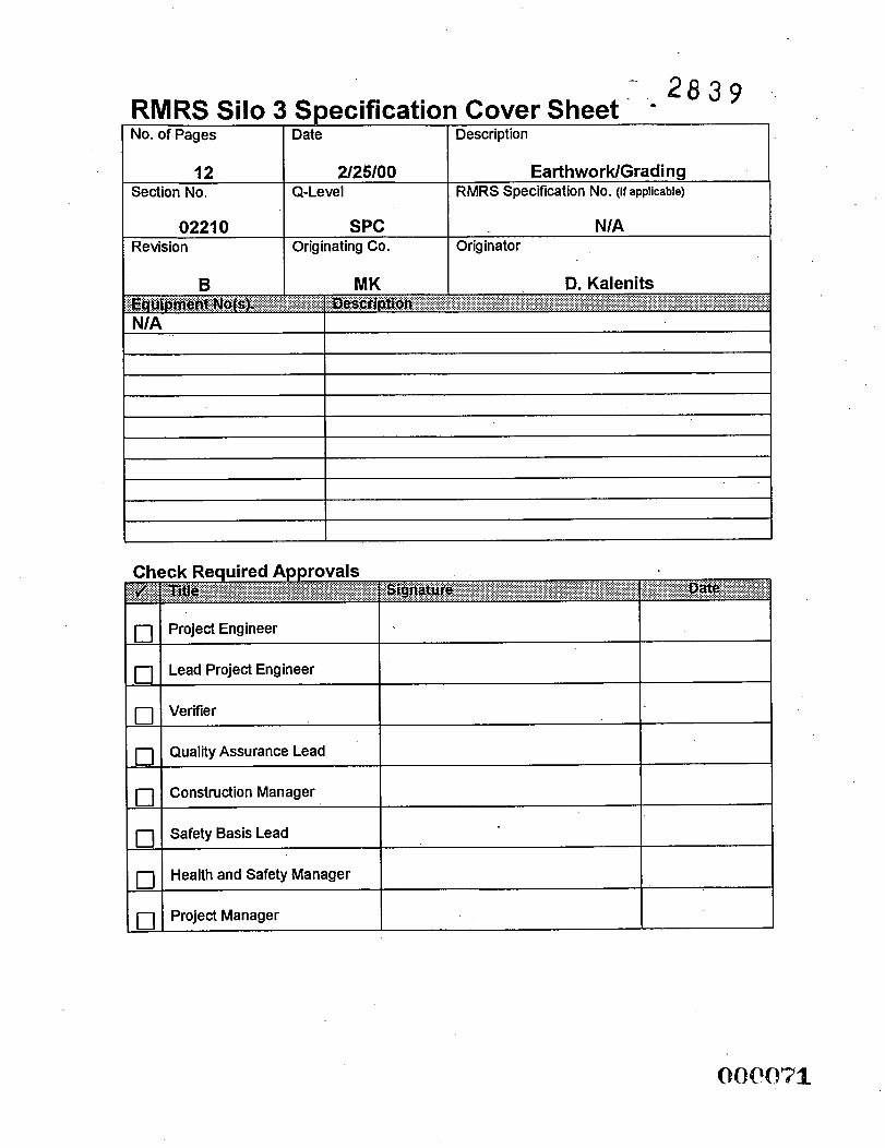
No. of Pages Date Description
12 Section No.
Project Engineer
Lead Project Engineer
Verifier
Quality Assurance Lead
Construction Manager
Safety Basis Lead
Health and Safety Manager
Project Manager
2/25/00 EarthworWGrading Q-Level RMRS Specification No. (If applicable)
0221 0 Revision
SPC N/A Originating Co. Originator
EarthworWGrading Spec . Section: 02210
Revision: B Rocky Mountain Remediation Services. L L C .
p r o r e r U n g U n ~ m ~ n n 8 n f
ALA & - RMRS ...
I- 2 8 3 9
SECTION 02210
EARTHWOWGRADING
TABLE OF CONTENTS
PART 1 GENERAL .................................................................................................................. 1 1.1 SECTION INCLUDES .................................................................................................. 1 1.2 RELATED SECTIONS ................................................................................................. 1 1.3 REFERENCES .............................................................................................................. 1 1.4 DEFINITIONS ............................................................................................................... 2 1.5 SUBMITTALS ............................................................................................................... 3 1.6 GENERAL PROCEDURES ........................................................................................... 3 1.7 WEATHER CONDITIONS .......................................................................................... -3 1.8 QUALITY ASSURANCE .............................................................................................. 4 1.9 PROJECT/SITE CONDITIONS .................................................................................... 4
PART 2 PRODUCTS ............................................................................................................... 4 BORROW MATERIAL ............................................................. : ................................... 4 2.1
.............................................................................................................. 4 GENERAL EXCAVATION REQUIREMENTS ............................................................ 4
7 USE OF EXCAVATED MATERIALS .......................................................................... GENER4L BACKFILL REQUIREMENTS .................................................................. 7
3.4 COMPACTION 9 FIELD TESTING CONTROL ....................................................................................... 9
3.7 PROTECTION ............................................................................................................ 10
PART 3 EXECUTION 3.1 3.2 3.3
3.5 3.6
3.8
.............................................................................................................
FINISHED EXCAVATION, FILLS, AND BERMS .................................................... 10
ADJUSTMENT OF EXISTING STRUCTUEES ......................................................... 11
February 25. 2000 i
000072 RMRS EarthworkjlGrading
EathworWGrading Rocky Mountain Spec. Section: 02210
Revision: B - RMRS Remediation Services, LLC.
*a!!& . . .p rnecllnp(h.mvbonment
--- 2 8 3 9 SECTION 02210
EARTHWOWGRADING
PART 1 GENERAL
1.1 SECTION INCLUDES
A. This section covers the general requirements of earthwork construction relative to the construction of the site preparation general site grading, underground piping construction, roadway construction and paving construction.
B. The work includes hrnishing of all equipment, labor, materials and supplies to complete the work to the lines and grades shown on the Project Drawings. .
1.2 RELATED SECTIONS
A. Section 02001 - Site Work General Provisions
B. Section 02005 - Surveying Services
C. Section 02935 - Seeding
D. Section 02485 - Soil Erosion And Sedimentation Control
1.3 REFERENCES
A. The publications listed below form a part of this specification to the extent referenced. The publications are referred to in the text by basic designation only.
B. ASTM - American Society for Testing and Materials
ASTM D422 - (1963; R 1990) Particle-Size Analysis of Soils
ASTM D698 - (1991) Laboratory Compaction Characteristics of Soil Using Standard Effort
ASTM D 1556 - (1 990) Density and Unit Weight of Soil in Place by the Sand-Cone Method
ASTM D2 167 - (1994) Density and Unit Weight of Soil in Place by the Rubber Balloon Method 0041073
RMRS EarthworwGrading February 25,2000 1 of 11
Earthwor WGrading Spec. Section: 0221.0
Rocky Mountain Revision: B 2 8 3 9 Remediatkn Services, LLC. - RMRS ...p r n b c U n g O n ~ m I m n m ~ n 1
ASTM D2216 - (1992) Laboratory Determination'of Water (Moisture) Content of Soil, and Rock
ASTM D2487 - (1993) Classification of Soils for Engineering Purposes (Unified Soil Classification System)
ASTM D2922 - (1 99 1) Density of Soil and Soil-Aggregate in Place by Nuclear Methods (Shallow Depth)
ASTM D3017 - (1988; R 1993) Water Content of Soil and Rock in Place by Nuclear Methods (Shallow Depth)
ASTM D43 18 - (1993) Liquid Limit, Plastic Limit, and Plasticity Index of Soils
1.4 DEFTNITIONS
A. Suitable Materials: Suitable materials classifjl as GW, GP, GC, GM, SW, SP, SC, SM, CL, CH, ML and MH according to ASTM D 2487. Material which classifies as CH shall not be used as fill beneath structures or paved roads consisting of concrete or asphaltic concrete. Bedrock materials which have been altered to soil-like characteristics which classii according to ASTM D 2487 as the above materials shall be considered suitable. Non-cohesive materials identified as GW, GP, GM, SW, or SP are not suitable for use as fill in berms.
B. Unsuitable Materials: Unsuitable materials include all materials that are not defined in Article 1 . 4 4 Suitable Materials. In addition, unsuitable materials are materials that classic as Pt, OL, or OH according to ASTM D 2487. Unsuitable materials also include all material that contains debris, refbse, roots, organic matter, frozen material, stone having a maximum dimension larger than 3 inches in any dimension, or other materials that are determined by the Contractor as unsuitable for providing a stable subgrade or stable foundation. Frozen materiaVfiozen subgrade shall be defined as soil with a temperature less than 32°F when measured with a thermometer, and containing visible ice crystals or clods of fiozen soil larger than 4 inches in diameter. Frozen materidfrozen subgrade may be reworked to become suitable material by melting ice crystals or breaking down fiozen clods. Otherwise, suitable material which has excess moisture content shall not be classified as unsuitable material unless it cannot be dried by manipulation, aeration, or blending with other materials as determined by the Contractor.
C. Random Fill: Random fill for containment berms shall classifjl as GC, SC, SM, CL, CH, ML and MH according to ASTM D 2487. Bedrock materials which have been altered to soil-like characteristics which classify according to ASTM D 2487 as the above materials shall be considered suitable.
OCP074 February 25.2000 2of 11 RMRS EarthworwGrading
EaAhworWGrading Spec. Section: 02210
Rocky Mountain Revision: B 2 8 3 9
Remediatiin Services, LLC. ... pmbcUng(h. mvhnmm: - RMRS
/
i D. Select Granular Material: Select granular material shall consist of well-graded sand;
gravel; crushed gravel; crushed stone or crushed slag composed of hard, tough, and durable particles; and shall contain not more than 10 percent by weight of material passing a No. 200 meih sieve and no less than 95 percent by weight passing a I-inch sieve. In addition, select granular material shall dassie as GW, GW-GM, GW-GC, GP, GP-GM, GP-GC, SW, SW-SM, SW-SC, SPY SP-SM, or SP-SC according to ASTM D 2487. The maximum allowable aggregate size shall be % inches or the maximum size recommended by the pipe manufacturer, whichever is smaller.
E. Initial BackfXl Material: Initial backfill shall consist of select granular material or suitable materials fiee from cobbles 3 inches or larger in any dimension, or fiee fiom cobbles, gravel, or stone of such size as recommended by the pipe manufacturer, whichever is smaller.
F. Cohesionless and Cohesive Materials: Cohesionless materials include materials classified as GW, GP, SW, and SP according to ASTM D 2487. Cohesive materials include materials classified as GC, SC, ML, CL, MH, and CH. Materials classified as GM and SM will be identified as cohesionless only when the fines are nonplastic.
G. Pavements: Pavements shall include all roads, walk areas, graveled surfaces, or any other type of surfaced area for driving or walking.
H. Degree of Compaction: Degree of compaction shall be expressed as a percentage of the maximum density obtained by the test procedure presented in ASTM D 698.
1.5 SUBMITTALS
Test reports and analyses certifjlng that suitable materials proposed for use at the project site conform to the specified requirements shall be conducted in accordance with Article 1.4, Definitions and Article 3.5, Field Testing Control.
1.6 GENERAL PROCEDURES
A. Subcontractor shall survey and lay out work in accordance with Section 02005.
1.7 WEATHER CONDITIONS
A. At the Contractor’s discretion, cut and fill materials may not be placed, spread, or compacted during adverse weather conditions. Subcontractor shall schedule work activities to minimize potential weather interruptions so that work areas will have minimum exposure to adverse weather conditions. In the event interruptions occur, no additional compensation will be provided for delay or material drying time. When the work is interrupted by adverse weather, fill operations shall not be resumed without prior Contractor approval.
Febnrcuy 25,2000 3 of 11
Ea GhworWGrading Spec. Section: 02210
Rocky Mountain ' - 2 8 3 9 . Revision: B Remediation Services, LLC. ... pmaKUnpUmemhnmmc
- RMRS
1.8 PROJECT/SITE CONDITIONS
A. Perform work in accordance with Section 02001, Site Work General Provisions, the Subcontractor's Statement of Work, and drawings, procedures, and other documents provided by the Contractor.
PART 2 PRODUCTS
2.1 BORROWMATERIAL
A. Soil required for fills in excess of suitable material produced by the excavations within the grading limits shall be excavated from an area designated by the Contractor.
PART 3 EXECUTION
3.1 GENERAL EXCAVATION REQUIREMENTS
A.
B.
C.
Excavation of every description, regardless of material encountered, -within the grading limits of the Project shall be performed to the lines and grades indicated on Drawings including removal of existing culverts. Suitable excavated material shall be transported to and placed in fill areas within the limits of the Work. Unsuitable material encountered within the limits of the Work shall be excavated below the grade indicated and replaced with suitable material as discussed in subsequent paragraphs. Unsuitable material shall be placed in a location approved by the Contractor.
Subgrade: Following excavation, the upper 6 inches of the subgrade shall be sampled at a minimum fiequency of once per '/z acre to identlfy subgrade materials as either suitable or unsuitable. Where unsuitable materials are encountered, four additional samples shall be collected surrounding the unsuitable material to define the areal extent of unsuitable subgrade material. Visual examination by the Contractor of the subgrade may also be used to identify unsuitable soil areas. If suitable material is present, it shall be tilled to a depth of 6 inches and compacted. If unsuitable material is encountered, it shall be excavated, replaced with suitable material, and compacted as directed by the Contractor.
Trench Excavation: During excavation, material suitable for backfilling shall be stockpiled in an orderly manner at a distance from the banks of the trench equal to one-half the depth of the excavation, but in no instance closer than 2 feet. Excavated material not required or not suitable for backfill shall be placed as directed by the Contractor. Grading shall be done as necessary to prevent surface water fiom flowing into the excavation, and any water accumulating therein shall be removed to maintain stability of the bottom and sides of the excavation. Unauthorized over-excavation shall
February 25,2000 4 o f l l RMRS EarthworVGrading 0 0 I) 7 6
Eaihwor WGrading Spec. Section: 02210
Rocky Mountain 2 8 3 9 Revision: B Remediation Services, LLC. . . . pmhcUng Ih. ~mlmnmcnl
- RMRS
be backfilled in accordance with Article 3.3, General Backfill Requirements, and Article 3.4, Compaction, at the expense of the Subcontractor. The trench shall be excavated to the dimensions as recommended by the manufacturer of the pipe to be installed. Trench walls below the top of the pipe shall be sloped and of such width as recommended in the manufacturer‘s installation manual. Trench walls more than 4 feet high shall be shored, cut back to a stable slope, or provided with equivalent means of protection for employees who may be exposed to moving ground or cave in. Trench walls which are cut back shall be excavated to at least the angle of repose of the soil. Special attention shall be given to slopes which may be adversely affected by weather or moisture content. The trench width below the top of pipe shall not exceed 24 inches plus pipe outside diameter (O.D.) for pipes of less than 24 inches inside diameter (I.D.) and shall not exceed 36 inches plus pipe outside diameter for sizes larger than 24 inches I.D.
1. Bottom Preparation: Trench bottoms shall be over excavated to allow installation of granular bedding, as detailed on the Drawings. Trench bottoms shall be accurately graded to provide uniform bearing and support for the bottom quadrant of each section of the pipe. Stones of 3 inches or greater in any dimension or as recommended by the pipe manufacturer, whichever is smaller, shall be removed to avoid point bearing.
2. Removal of Unsuitable or Unstable Material: Where unsuitable’or otherwise suitable material is encountered that is too wet to properly support appurtenant structures, as determined by the Contractor, such material shall be removed to the depth directed and replaced to the proper grade with suitable material as described in Article 1.4A., Suitable Materials. Select granular material shall be provided to replace unsuitable material. When removal of unsuitable or unstable material is required due to the fault or neglect of the Subcontractor in his performance of the work, the resulting material shall be excavated and replaced at the expense of the Subcontractor.
3. Excavation for Appurtenances: Excavation for manholes, catch-basins, or similar structures shall be sufficient to leave at least 24 inches clear between the outer structure surfaces and the face of the excavation or support members. Rock shall be cleaned of loose debris and cut to a firm surface either level, stepped, or serrated, as shown or as directed. Loose disintegrated rock and thin strata shall be removed. Removal of unsuitable material shall be as specified above. When concrete or masonry is to be placed in an excavated area, special care shall be taken not to disturb the bottom of the excavation. Excavation to the final grade level shall not be made until just before the concrete or masonry is to be placed.
4. Jacking, Boring, and Tunneling: Unless otherwise indicated, excavation shall be by open cut, except that sections of a trench may be jacked, bored, or tunneled if, in the opinion of the Contractor, the pipe, cable, or duct can be safely and properly installed and backfill can be properly compacted in such sections.
February 25.2000 5 of 11 RMRS EarthworwGrading OOPO”37
- RMRS
Ea Ahwor WGrading Spec. Section: 02210
Rocky Remediation Mountain Services, LLC. - - 2 8 3 9 Revision: B . . . prntrcllng Um wwlronmnl
5 . Interim Piles: Separate differing materials with dividers, or stockpile apart to prevent mixing. Direct surface water away from stockpile site to prevent erosion or deterioration of materials. Provide storm water runoff controls at pile to prevent sediment from leaving stockpile area.
6. Forty-five (45) calendar days shall be the maximum time that a stockpile can be left in an exposed condition without stabilization. Stockpiles that are expected to be inactive for a period of 45 calendar days or more, as determined by the Contractor, shall be stabilized within seven (7) calendar days after last activity. Stockpiles shall be stabilized by means of a crusting agent, as specified in this section. Slopes on pile shall not exceed 2: 1 in steepness and shall be less than 15 feet in height. Pile shall be shaped with a drainage pitch of at least 2% on all areas. The perimeter of the pile shall have proper sediment controIs (i.e., silt fence). The subcontractors are responsible for maintaining the controls on the piles until final acceptance or disposition.
7. Stockpiles: Stockpiles shall be kept in a neat and well drained condition, giving due consideration to drainage at all times. Adequate drainage shall be provided for the stockpiles and surrounding areas by means of ditches, dikes, or other Contractor-approved methods. The ground surface at stockpiie locations shall be cleared and grubbed. Excavated suitable and unsuitable materials shall be separately stockpiled. Stockpiles of suitable materials shall be protected from contarriination which may destroy the quality and fitness of the stockpiled material. If the Subcontractor fails to protect the stockpiles, and any material becomes unsuitable, such material shall be removed and replaced with suitable material from approved sources at the expense of the Subcontractor.
8. Dewatering: Each excavation shall be kept dry during subgrade preparation and continually thereafter until the structure to be built or the pipe to be installed therein is completed. Surface water shall be diverted or otherwise prevented from entering excavated areas or trenches to the greatest extent practical without damaging adjacent property. The Subcontractor shall perform work in accordance with Contract Documents to dispose of all water generated during dewatering activities. The Subcontractor shall be responsible for a11 damage incurred to the drainage facilities as a result of dewatering operations. All pipe or conduits shall be left clean and free of sediment.
9. Excavations shall be sloped to sumps and/or graded to drain to ditches or channels discharging to a sediment basin, sediment trap, or other locations as directed by the Contractor. Excavations are to be kept free of standing water.
As excavation progresses, excavated depressions in the excavated area to be used as temporary sumps. Water accumulated in sumps shall be pumped, via portable
10.
February 25,2000 6of 11 RMRS EarthworWGradin@ 078
Ea; hworWGrading Spec. Section: 02210
Remediation Rocky Mountain Services, LLC. = 2 8 3 9 Revision: B . . . pmtuunp me emlmnment
sump pump system and flexible hose, to the nearest ditch or channel discharging to the sediment basin or sediment trap upon approval of the Contractor.
D. Excavation Beneath Paved Areas: Excavation under areas to be paved shall extend to the bottom of the aggregate base. After the required excavation has been completed, the exposed surface shall be scarified, brought to optimum moisture content and compacted to 95 percent of maximum density.
3.2 USE OF EXCAVATED MATERIALS
A. Suitable material removed fiom required excavation under this Section shall be used in the formation of sub-grades, slopes, backfill , and for such other purposes as directed. No excavated material shall be wasted without the authorization of the Contractor. Material authorized to be wasted shall be disposed of as directed and in a manner that will not obstruct the flow characteristics of any stream or impair the efficiency or appearance of any structure. No excavated material shall be deposited at any time in a manner that may endanger a partly finished structure by direct pressure by overloading banks contiguous to the operations, or that may in any other way be detrimental to the completed work.
3.3 GENERAL BACKFILL REQUIREMENTS .
A.
B.
All vegetation, such as roots, brush, heavy sods, heavy growth of grass, and all decayed vegetable matter, rubbish, and other unsuitable material within the area upon which fill is to be placed, shall be stripped or otherwise removed before the fill is started. In no case shall unsuitable material remain in or under the fill area. Stumps, logs, and roots more than 1% inches in diameter shall be excavated and removed to a depth not less than 18 inches below the original ground surface. Sloped ground surfaces steeper than 1 vertical to 4 horizontal on which fill is to be placed shall be plowed, stepped, or broken up, as directed, in such manner that the fill material will bond with the existing surface. Prepared surfaces on which compacted fill is to be placed shall be wetted or dried as may be required to obtain the specified moisture content and density.
Trench Backfill: Backfill material shall consist of suitable material, select granular material, or initial backfill material, as required. Backfill shall be placed in layers not exceeding 6 inches loose thickness for compaction by hand-operated machine compactors, and 8 inches loose thickness for compaction with heavy compaction equipment, unless otherwise specified. The moisture content of cohesive soil shall be between 1 percent below and 3 percent above optimum moisture when compacted. Cohesionless soils shall be compacted at a moisture content as required to facilitate compaction without bulking. Trenches shall be backfilled to the grade shown. The trench shall be backfilled to 2 feet above the top of pipe prior to performing the required pressure tests. Joints shall be left uncovered during the pressure test. The trench shall not be backfilled completely until all specified tests are performed.
Febnrary 25, 2000 7o f l l RMRT EhrthworWGrading OQPro79
Ea Ahw or WGrading
C.
- Rocky Mountain Remediation Services, LLC. . . . pmMUng Ih. mvlmnminl
Spec. Section: 02210 2 8 3 9 Revision: -B
1. Replacement of Unsuitable Material: Unsuitable material removed from the bottom of the trench or excavation shall be replaced with random fill placed in layers not exceeding 6 inches loose thickness.
2. Bedding: Bedding shall conform to the details s h o w on the Drawings and specified below. Material shall be deposited in 6-inch loose layers and compacted with approved methods to at least 95 percent maximum density. Care shall be taken to ensure thorough compaction of the fill under the pipe haunches. Bedding shall consist of select granular materials.
3. Initial Backfill: Initial backfill shall be placed in 6-inch loose thickness layers and compacted to at least 95 percent of maximum density within moisture content ranges as specified in Article 3.4, Compaction. Initial backtill material shall be placed and compacted with approved tampers to a height of at least 1 foot above the utility pipe or conduit. The backfill shall be brought up evenly on both sides of the pipe for the full length of the pipe. Care shall be taken to ensure thorough compaction of the fill under the haunches of the pipe.
4. Final Backfill: The remainder of the trench shall be filled with suitable material placed in loose thickness layers a maximum of 8 inches and compacted according to Article 3.4D, Piping.
Prepared Subgrade: Suitable materials shall be used in bringing fills and backfills to the lines and grades indicated and for replacing unsuitable materials. Suitable materials shall be placed in horizontal layers not exceeding 8 inches in loose thickness, or 6 inches when hand-operated compactors are used. After placing, each layer shall be plowed, disked, or otherwise broken up; moistened or aerated as necessary; and thoroughly mixed and compacted as specified. Backfilling shall not begin until construction below finish grade has been approved; underground utility systems have been inspected, tested, and approved; forms removed; and the excavation cleaned of trash and debris. Backfill shall be brought to indicated finish grade. Backfill shall not be placed in wet or frozen areas. Heavy equipment for spreading and compacting backfill shall not be operated closer to foundation walls than a distance equal to the height of backfill above the top of each footing; the area remaining shall be compacted in layers not more than 4 inches in compacted thickness with power-driven hand tampers suitable for the material being compacted. Backfill shall be placed carehlly around pipes to avoid damage. Backfill shall not be placed against foundation walls prior to seven days after completion of the walls. As far as practical, backfill shall be brought up evenly on each side of the wall and sloped to drain away from the wall.
February 25,2000 8of 11
Rocky Mountain Remediatiin Services, LLC.
*a& RMRS
EarthworWGrading Spec. Section: 02210
2 8 3 9 Revision: B L_ ... pmtrcUngUwwwhnmm1
3.4 COMPACTION
A.
B.
C.
D.
Compaction shall be accomplished by means specified and to the following densities for various parts of the work. Deficiencies in construction shall be corrected by the Subcontractor at no additional cost to the Contractor.
Prepared Subgrade: the prepared subgrade shall be constructed to the lines and grades shown on the drawings. This material shall be compacted to a density of at least 95% of the maximum density determined by ASTM D 698. Moisture content shall be between 2% below and 2% above optimum moisture content when compacted.
Beneath Structures: Each layer of cohesive fill shall be compacted to at least 95 percent of maximum density as defined in Article 1.4.H., Degree of Compaction. Cohesionless fill shall be compacted to at least 97 percent of maximum density as defined in Article 1.4.1. - Degree of Compaction.
Piping: Fill above piping that is located beneath structures shall be compacted to at least 95% of maximum density as defined by ASTM D698.
3.5 FIELD TESTING CONTROL
A.
B.
C.
Sampling and Testing: All quality control sampling and testing shall be performed by the Subcontractor in accordance with Subcontractor’s Statement of Work, and as specified herein.
Moisture-Density Determinations: Tests for determining maximum density and optimum moisture shall be performed by the Subcontractor in accordance with ASTM D 698. Samples shall be representative of the materials to be placed. An optimum moisture-density curve shall be obtained for each principal type of material or combination of materials encountered or used. Results of these tests shall be the basis of control for compaction. A copy of these tests shall be hrnished to the Contractor.
Density Control: To ensure placement of materials within the limits of densities specified, Subcontractor shall adequately control his compaction operations by tests made in accordance with any of the following methods: ASTM D 1556, ASTM D 2167, or ASTM D 2922 and ASTM D 3017. 1 . Areas to Receive Pavement: Areas to receive pavement shall be tested at the
frequency of one test per 1,500 square yards.per lift of fill material. 2. Piping: Areas beneath and above piping shall be tested at the frequency of one
test per 250 lineal feet of pipe installation for each lift of fill or bedding material placed. I ,’
February 25, 2000 9 of 11
EarthworWGrading Spec. Section: 022 10
Revision: B +- 2 8 3 9 Rocky Mountain
Remediation Services, LLC. ... pmMUng(h. *nvhnmenf - RMRS
3.6 FINISHED EXCAVATION, FILLS, AND BERMS
A. All areas covered by the Project, including excavated and filled sections and adjacent transition areas, shall be uniformly smooth graded. The finished surface shall be reasonably smooth, compacted, and fiee fiom irregular surface changes. Degree of finish shall be that ordinarily obtainable fiom either blade-grader or scraper operations, except as otherwise specified. The finished surface shall be not more than 0.1 foot above or below the established grade or approved cross section and shall be fiee of depressed areas where water would pond. All ditches shall be finished to drain readily. The surface of berms or excavated areas for road construction or other areas to be paved on which a base course or pavement is to be placed shall not vary more than 0.05 foot from the established grade and approved cross section.
B. Stabilization of disturbed areas by interim seeding or by use of a crusting agent shall be performed at completion of excavation or which are planned to be left idle for more than forty-five (45) days shall be stabilized within seven (7) days after the last activity. Soils shall be stabilized by one of the following methods as directed by the Contractor :
1.
2.
Crusting agents shall be applied in accordance with manufacturer's recommendations as specified in this Section. Interim seeding shall be applied as specified in Section 02900.
C. Forty-five (45) calendar days shall be the maximum time that a stockpile can be left in an exposed condition without stabilization. Stockpiles that are expected to be inactive for a period of 45 calendar days or more, as determined by thecontractor, shall be stabilized within seven (7) calendar days after last activity. Stockpiles shall be stabilized by means of a crusting agent.
3.7 PROTECTION
A. During construction, berms and excavations shall be kept shaped and drained. Ditches and drains along the subgrade shall be maintained in a manner to drain effectively at all times. Where ruts occur in the berms, the subgrade shall be brought to grade, reshaped if required, and recompacted. Newly graded areas shall be protected from tr&c or erosion, and any settlement or washing away that may occur from any cause prior to acceptance shall be repaired and grades reestablished to the required elevations and slopes. All work shall be conducted in accordance with the environmental protection requirements of the Contract.
B. Protection of Existing Service Lines and Utilities Structures: Existing utility lines that are shown on the Drawings, or the locations of which are made known to the Subcontractor prior to excavation that are to be retained, as well as utility lines constructed during excavation operations, shall be protected from damage during excavation and backfilling, and if damaged, shall be repaired by the Subcontractor at
February 25,2000 10 of 11 OOPC82 RMRS EarthworWGrading
Eart hworWGrading Spec. Section: 022 10
RMRS Rocky Mountain " - 2 8 3 9 Revision: B Remediation Services, LLC. . . . p m ~ U n g Um ombnmonf -
their expense. In the event that the Subcontractor damages any existing utility lines that are not shown, or the locations of which are not made known to the Subcontractor, report thereof shall be made immediately to the Contractor. If determined that repairs are to be made by the Subcontractor, such repairs will be made at no additional cost to the Owner. When utility lines that are to be removed or relocated are encountered within the area of operations, the Subcontractor shall notify the Contractor in ample time to prevent interruption of the service.
3.8 ADJUSTMENT OF EXISTING STRUCTURES
A. All manholes, valve boxes, or inlets of any nature within the project that do not conform to the new finish grade in either surfaced or unsurfaced areas shall be adjusted to the new finish grade. Where inlets, manholes, or valve boxes fall within a surfaced or unpaved roadway or parking, the existing fiames and cover shall be removed and replaced with a heavy-duty frame and cover. The structure shall be adjusted as needed to fit the new conditions. All structures shall be of a type suitable for the intended use and shall conform to the requirements of the applicable section of these Specifications.
END OF SECTION
Febnrary 25,2000 11 of 11
No. of Pages
9
Section No.
Date Description
2/25/00 Excavating and Backfilling for Foundations and Structures
Q- Leve I RMRS Specification No. (If applicable)
B
02220 Revision
MK
SPC N/A Originating Co. Originator
D. Kalenits
(7
(7
(7
(7
0
Project Engineer
Lead Project Engineer
Verifier
Quality Assurance Lead
Construction Manager
Safety Basis Lead
Health and Safety Manager
Project Manager
Excavating & Backfilling for Foundation & Structures Rocky Mountain S ec . Section: 02220 Remediation Services. L L C . . 2 8 3 # Revision: B RMRS ... pmscllnglheenvhnment .
SECTION 02220
EXCAVATING & BACKFILLING FOR FOUNDATION &'STRUCTURES
TABLE OF CONTENTS
PART 1 GENERAL ....... i ............................................................................................................ 1 1.1 DESCRIPTION ............................................................................................................. 1 1.2 RELATED SECTIONS ................................................................................................. 1 1.3 REFERENCES .............................................................................................................. 1 1.4 QUALITY ASSURANCE .............................................................................................. 2 1.5 SUBMITTALS .............................................................................................................. 2 1.6 PROJECT/SITE CONDITIONS .................................................................................... 3
PART 2 PRODUCTS ............................................................................................................... 3 MATERIALS ................................ : ................................................................................ 3 2.1
PART 3 EXECUTION ............................................................................................................ 4 3.1 EXCAVATION ............................................................................................................. 4 3.2 BACKFILLING ............... : ............................................................................................. 6 3.3 COMPACTION ............................................................................................................. 7 3.4 MAINTENANCE .......................................................................................................... 8 3.5 CLEANING ................................................................................................................... 8
Februav 25. 2000 i (ECP08S RMRS Ercmating & Backftlling for F d a t i o n s & Structures
Excavating & Backfilling for Foundation & Structures - -- 2 8 3 9 Spec. Section: 02220
Revision: B Rocky Mountain Remediation Services, LLC. ... pmMllkg(h.rmhnm*nt
RMRS
SECTION 02220
EXCAVATING & BACKFILLING FOR FOUNDATION & STRUCTURES
PART 1 GENERAL
1.1 DESCRIPTION
A. Provide all excavating, backfilling and compacting of soil for foundations and structures in accordance with this specification section and other Contract Documents.
1.2 RELATED SECTIONS
A. Section 02001 - Site Work General Provisions
B. Section 02210 - EarthworWGrading
C. Section 03300 - Cast-in-Place Concrete
D. Section 02485 - Soil Erosion And Sedimentation Control .
1.3 REFERENCES
A. ASTM - American Society for Testing and Materials
1.
2.
3.
4.
5.
ASTM D698 - Test Methods for Laboratory Compaction Characteristics of Soil Using Method Effort .
ASTM D2216 - Method for Laboratory Determination of Water (Moisture) Content of Soil, Rock, and Soil-Aggregate Mixtures.
ASTM D2922 - Test Methods for Density of Soil and Soif-Aggregate in Place by Nuclear Methods (Shallow Depth).
ASTM D3017 - Test Methods for Moisture Content of Soil by Nuclear Methods
ASTM D43 18
B. OSHA - Occupational Safety and Health Administration, U.S. Department of Labor.
1. 10 CFR Part 1910 - General Industry Standards
Februaty 25,2000 1 of8 RMU Excavating & Backjllling for Foundations & structure^
Excavating & Backfilling for Foundation & Structures Spec. Section: 02220 - 2 8 3 9 Revision: B
Rocky Mountain Remediation Services, LLC. ... ~rotufb~gCh.mvhnsr.n(
RMRS
2. 10 CFR Part 1926 - Construction Industry Standards
1.4 QUALITY ASSURANCE
A.
B.
C.
D.
E.
F.
G.
Comply with all applicable federal, state and local codes, .ordinances and regulations, and site requirements.
Comply with all applicable OSHA regulations, including 10 CFR Part 1910 - General Industry Standards and 10 CFR Part 1926 - Construction Industry Standards.
The Contractor will determine by observation and test reviewing the quality of work and materials during excavating and backfilling operations. The Contractor will judge the suitability of bearing material at excavated levels, acceptability of backfill material, and the correct placement, and compaction of fill and backfill to specified densities. Any'work found unsatisfactory shall be corrected.
Field Tests: The following field tests shall be performed at the rate of one for every 200 cubic yards or at least once per shift when fill is being placed.
1.
2.
Field in-place Nuclear density tests shall be performed per ASTM D 2922.
Field in-place Moisture content determination shall be performed per ASTM D 698.
Laboratory testing of soil samples shall be performed at the rate of one for every 250 cubic yards or any part thereof.
1.
2.
Perform laboratory compaction test per ASTM D698.
Perform moisture content test per ASTM D2216.
Re-Testing: For aII tests that fail to meet the requirements for density and/or moisture as specified herein, the Subcontractor shall, at no change in Contract Amount, provide additional compaction or other-work as required to meet specifications. Subcontractor shall bear the cost of all re-testing, including additional cost of testing incurred by the Contractor.
Test Locations: Shall not serve as a guaranteed indication that all compacted areas meet the minimum requirements, but it shall be the Subcontractor's responsibility that all the soils be compacted to at least the minimum requirements.
Febniary 25,2000
OQOQ87 2of8 RMRS Excavating & Bachjilling for Foundations & Structures
2 8 3 9 Excavating & Backfilling for Foundation & Structures
Rocky Mountain Spec. Section: 02220 Remediation Services, LLC. Revision: B ... p m l u U n g h . * m h n m ~ n t
A. The Subcontractor will be responsible for the preparation of the following documents and will make these documents available to the Contractor.
. . - l . Report and certification of soils, washed rock, crushed stone and/or rounded gravel.
2.
3.
4. Field density/moisture test reports.
B. Test Reports: Shall contain the following information:
Test reports on soils, washed rock, crushed stone and/or rounded gravel.
Optimum moisture-maximum density curve for each different material.
1.
2.
3.
4.
5.
6.
Project identification and name.
Date of test.
Name of Subcontractor
Name of individual performing test@).
Location of test on Project Site.
Results of tests including wet and dry density, percentage of moisture and percentage of compaction.
1.6 PROJECT/SITE CONDITIONS
A. Perform work in accordance with Section 02001, Site Work General Provisions, the Subcontractor’s Statement of Work, and drawings, procedures, and other documents provided by the Contractor.
PART 2 PRODUCTS
2.1 MATERIALS
A. Fill Materials: All materials used as fill shall be competent soils fiee of clay, topsoil, organics, vegetation, debris, waste, frozen materials or any other deleterious materials. Materials may come fiom on-site excavations, or borrow areas designated by the Contractor. All materials used shall be approved, in advance, by the Contractor. Provide current soils tests of all imported materials and submit test results for approval by the Contractor prior to delivery of materials to the Project Site.
February 2s. 2000 3 of 8 RA4US Excavating & Backjilling f i r Foundatiotu & Smcctures
Excavating & Backfilling for Foundation & Structures Rocky Mountain Spec. Section: 02220
Revision: B 3 8 3 9 Remediatbn Services, LLC. . . . pmaCttng Um mvbunmml RMRS
-
PART 3 EXECUTION
3.1 EXCAVATION
A. Comply with all OSHA regulations, including those for excavation and trenching, site permits and safe work plans.Excavate according to grades and elevations indicated on the Project Drawings.
B. Excavate according to grade and elevations indicated on the Project Drawings.
1. Excavation shall include all materials encountered regardless of the nature thereof, as required to complete the Project to the grades and elevations indicated on the Drawings.
C. Stability of Excavations: Comply with all applicable OSHA regulations, as well as site permits and safe work plans.
D. Dewatering: Prevent surface water, subsurface water and ground water from flowing into the excavations and flooding the Project Site and surrounding areas.
1. Do not allow water to accumulate in excavations.
2. Remove water from excavations to prevent softening of foundation bottoms and soils changes detrimental to the stability of foundations.
3. Provide and maintain pumps, sumps, suction and discharge lines, and other dewatering system components necessary to convey water away from excavations.
4. Excavations shall be sloped to sumps and/or graded to drain to ditches or channels discharging to a sediment basin, sediment trap, or other locations as directed by the Contractor. Excavations are to be kept fiee of standing water.
5 . As excavation progresses, excavated depressions in the excavated area to be used as temporary sumps. Water accumulated in sumps shall be pumped, via portable sump pump system and flexible hose, to the nearest ditch or channel discharging to the sediment basin or sediment trap upon approval of the Contractor.
6. Convey water removed from excavations and rain water to collection areas or run-off areas.
7. Provide and maintain temporary drainage ditches and other diversions outside the excavation limits for each structure.
OOrOf?89 Februaty 2J.2000 4of8 RMIZS Excavating & Bacyilling for Foundations & Structures
Excavating & Backfilling for Foundation & Structures Rocky Mountain Spec. Section: 02220
Revision: B Remediation Services, LLC. - 2 8 3 9 . . .pmbcfbw (h. arnhnmenl
RMRS
E.
F.
G.
8. Provide and maintain silt control for water removed from excavations, diverted rain water and any other drainage which leaves the Project Site.
9. Do not use trench excavations or site utilities as temporary drainage ditches.
Excavating Under and Adjacent to Foundations: Obtain Contractor's approval before excavating under foundations or within a 45 degree slope from horizontal plane at bottom of foundations. Stability of all foundations must be ensured by means directed by the Contractor.
Material Storage: During excavation, stockpile excavated materials classified as suitable fill or backfill material in an orderly manner a sufficient distance from the edges of the excavation to avoid overloading, and to prevent slides or cave-ins.
1. Material Stockpiles A.
B.
C.
D.
Separate differing materials with dividers, or stockpile apart to prevent mixing
Direct surface water away from stockpile siteto prevent erosion or deterioration of materials; and
Provide storm water runoff controls at pile to prevent sediment fiom leaving stockpile area.
Forty-five (45) calendar days shall be the maximum time that a stockpile can be left in an exposed condition without stabilization. Stockpiles that are expected to be inactive for a period of 45 calendar days or more, as determined by the Contractor, shall be stabilized within seven (7) calendar days after last activity. Stockpiles shall be stabilized by means of a crusting agent, as specified in this section. Slopes on piles shall not exceed 2: 1 in steepness and shall be less than'l5 feet in height. Pile shall be shaped with a drainage pitch of at least 2 percent on all areas. The perimeter of the pile shall have proper sediment controls (i.e., silt fence). The Subcontractor is responsible for maintaining the controls on the piles until final acceptance or disposition.
2. Location designated by Contractor. 3.
4.
.
Pile excavated material in such a manner as to keep surface drainage of adjoining areas unobstructed. Place, grade and shape stockpiles for proper drainage.
Excavation for Structures: Conform to the elevations and dimensions shown on the Drawings, within a tolerance of plus or minus 1/10 foot, extending a sufficient distance fiom foundation to permit placing and removal of concrete form work, installation of services, other construction required and inspection.
1. In excavating for foundations, take care not to disturb bottom of excavations.
5of8 RMRS Excavating & Bacwlling for Foundations & S
RMRS i Excavating & Backfilling for Foundation & Structures
Rocky Mountain Spec. Section: 02220 . Remediatiin . . p r n s c U n a Ih. emlnuurent Services. LLC. - 2 8 3 9 Revision: B
2. Trim excavation bottoms to required lines and grades to leave a solid undisturbed base to receive concrete.
3. Remove rocks, boulders, portions of abandoned structures, abandoned utilities and other hard obstructions to a depth of at least 6 .inches below the specified excavation level and fill with approved fill material.
H. Excess Materials: Excavated material not required or not suitable for fill/backfill materials shall be disposed of per the Contractor’s instruction.
I. Cold Weather Protection: Protect excavation bottoms from freezing when the atmospheric temperature is less than 35 degrees F.
J. Seasonal Limits: Do not deposit, spread or compact fill material when it is frozen or thawing, or during unfavorable weather conditions. When the work in progress is interrupted by heavy rain or freezing weather, fill operations shall not be resumed until the Contractor inspects the fill, verifies that the condition of the previously placed fill is acceptable, and the moisture content and density of the previously placed fill is as specified.
K. Notification for Inspection of Excavation: Upon completion of excavation work and prior to commencing any work thereon, immediately notify the Contractor in order that soil types and conditions can be observed. Contractor shall observe and approve adequacy of base of excavation. If it is determined that soils conditions exist which require larger or deeper excavation than indicated on Drawings, n o t e the Contractor in writing of the necessary changes.
3.2 BACKFILLING
A. Comply with all OSHA regulations, including those for excavation and trenching, site permits and safe work plans.
B. Prior to trench Backfill Placement: Backfill excavations as promptly as the work permits, but not until completion of the following:
1. Acceptance by Contractor of all construction below finished grade.
2. Inspection, testing, approval and recording locations of underground utilities.
3. Removal of concrete form work.
4. Removal of shoring and bracing, and backfill of voids with satisfactory materials.
5 . Removal of trash and debris. oNw4p February 25,2000 6 of8 RMRT Excavating & BacyilIing for Foundations & Sbuctures
Excavating & Backfilling for Foundation & Structures Rocky Mountain Spec. Section: 02220 . Remediation . . pmt8cUng Ut* e n v h n m m l Services, LLC. Revision: B 3 8 3 9
6. Permanent or temporary horizontal bracing is in place on horizontally supported walls.
Concrete shall have attained at least 80 percent of its specified 28 day compressive strength before commencing backfilling and compacting operations.
7.
C. Fill and Backtill - General:
1.
2.
3.
4.
Scar@ and compact exposed surfaces before placing fill material. Remove unsuitable soil and replace it with approved material.
Place fill and backfill material in maximum 6 inch layers. Each layer shall be moistened as required and compacted with mechanical tampers or heavy compaction equipment.
Place backfill materials evenly adjacent to structures, to required elevations. a. Take care to prevent wedging action of backfill against structures by
carrying the material uniformly around the structure to approximately the same elevation in each layer. Place backfill in such a manner as to prevent damage to adjacent structures. b.
Compaction methods or equipment that produce horizontal or vertical earth pressures which may cause excessive displacement or overturning, or may damage structures, shall not be used.
3.3 COMPACTION
A. Compaction Requirements: Maximum dry density and optimum moisture shall be determined using Standard Proctor, ASTM D698. Minimum requirements for compaction of all fill and backfill materials shall be:
1. In-place Relative Density: 95 percent of maximum dry density.
2. In-place Moisture Content: k2 percent of optimum moisture.
B. Compaction Tests:
1.
2.
Will be performed by Contractor using in-place density test per ASTM D 1556 or ASTM D2922. Notification: Subcontractor shall give Contractor at least 24 hours advance notice of time required for inspecting and testing services.
Febniaty 25.2000 7 of 8 RMRS Excavating & Bacyilling for Foundations & Structures
Excavating & Backfilling for Foundation & Structures Rocky Mountain Spec. Section: 02220 Remediation Services, LLC. 5- 2 8 3 9 Revision: B . . . pmtuUng h e cnvImnment
RMRS
3 Compaction of fill and backfill material shall be tested at locations to be selected by Contractor. a. At a minimum, perform field density/moisture test for each 200 cubic yards of backfill or fill placed with at least one test per shift per ASTM D 2992 and ASTM D 698, respectively.
4. For all tests which fail to meet specifications for relative density and/or moisture, backfill material shall be removed, relaid and re-compacted, at Subcontractor's expense, until compacted material meets specifications. Subcontractor shall bear the cost of all re-testing, including cost of additional testing incurred by the Contractor.
C. Jetting or ponding shall not be allowed.
D. Compaction equipment: Use sheepsfoot compactor. 1. Materials which cannot be compacted with the specified compaction equipment
shall be compacted with handheld compactors in 6-inch lifts to a density equal to the density achieved by the specified compaction equipment and methods. Compaction of each layer shall proceed in a systematic, orderly and continuous manner.
3.4 MAINTENANCE
A. Protection of Graded Areas: Protect graded areas from traffic and erosion, and keep free of trash and debris. Repair and re-establish grades in settled, eroded and rutted area to the specified tolerances.
3.5 CLEANING
A. At all times keep the premises free fiom accumulation of waste materials or rubbish caused by employees or the Work. 1. Maintain all work area, material storage areas and maintenance areas in a clean
and safe condition at all times.
2. Promptly remove and dispose of excess materials, litter and debris. Leave all areas in a neat and clean condition. Accumulation of excess materials, litter and debris during execution of the work will not be permitted.
END OF SECTION
February 25,2000 8 of8 RMRS Excavating h Backfilling for Foundations & Structures
!"
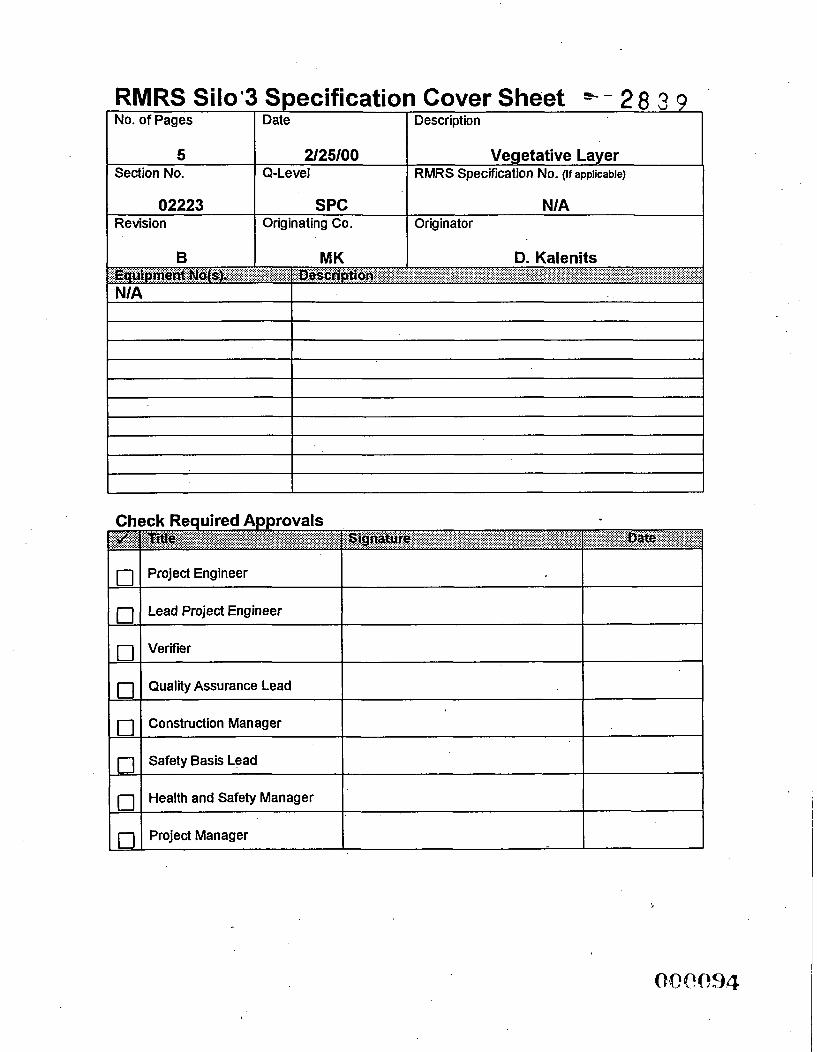
No. of Pages Date Description
0 0 0 0 0 0 0 0
Project Engineer
Lead Project Engineer
Verifier
Quality Assurance Lead
Construction Manager
Safety Basis Lead
Health and Safety Manager
Project Manager
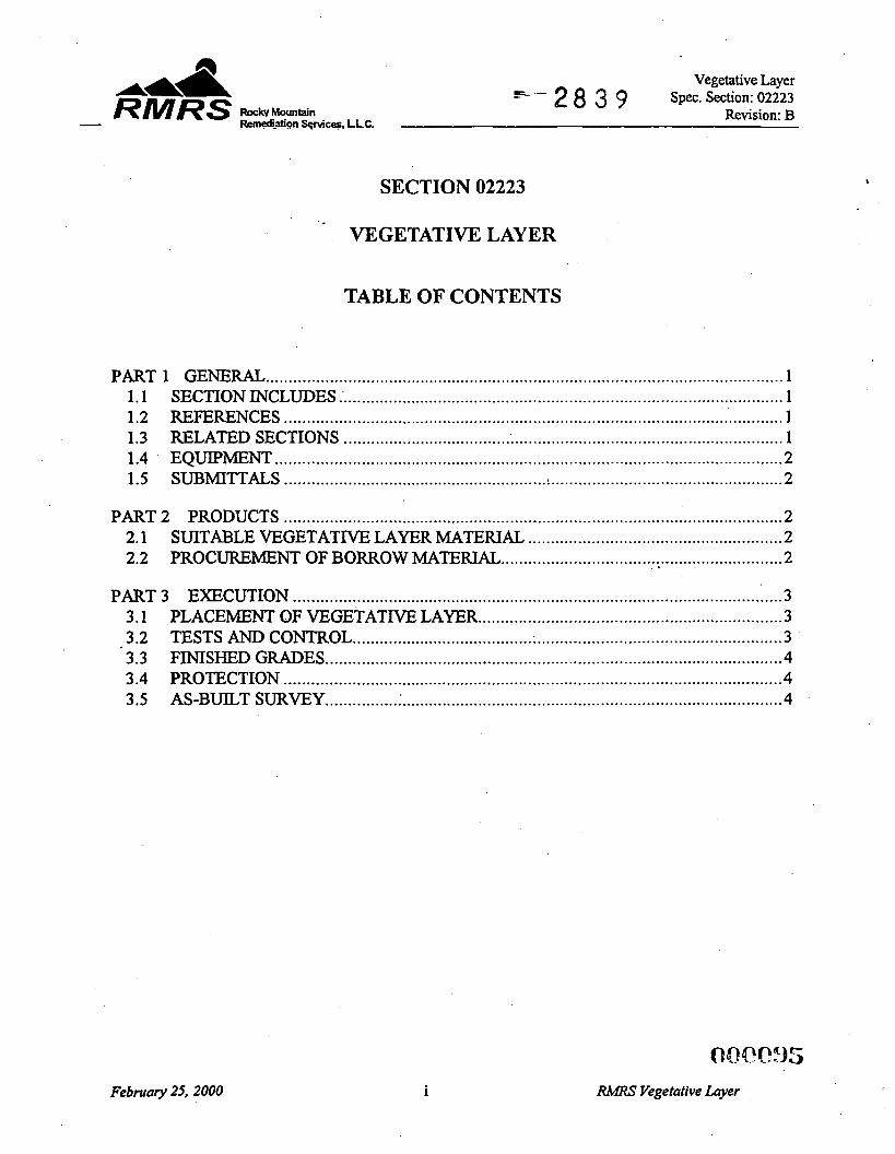
Vegetative Layer spec . Section: 02223 RMRS W M o u n t a i n Revision: B
C-. 2 8 3 9 - Remedi_atign Sqvi- . L L C .
SECTION 02223
VEGETATIVE LAYER
TABLE OF CONTENTS
PART 1 GENERAL .................................................................................................................. 1 1 . 1 SECTION INCLUDES ................................................................................................... 1 1.2 REFERENCES .............................................................................................................. 1 1.3 RELATED SECTIONS ................................................................................................. 1 1.4 EQUlPMENT ................................................................................................................ 2 1.5 SUBMITTALS .......................................................... : ................................................... 2
. .
PART 2 PRODUCTS .............................................................................................................. 2 SUITABLE VEGETATIVE LAYER MATENAT-, ........................................................ 2 PROCUREMENT OF BORROW MATERIAL .............................................................. 2
2.1 2.2 .
PART 3 EXECUTION ............................................................................................................ 3 3.1 PLACEMENT OF VEGETATIVE LAYER .................................................................. -3 3.2 TESTS AND CONTROL .......................................... : .................................................... 3 3.3 FINISHED GRADES ..................................................................................................... 4 3.4 PROTECTION .............................................................................................................. 4 3.5 AS-BUILT SURVEY ................ .................................................................................... 4
February 25. 2000 i RMRS Vegetative Layer
Vegetative Layer Spec. Section: 02223 RMRS RockvMountain -- 2 8 3 9 Revision: B - Remgli.dgn Sqmicq. LLC.
Vegetative Layer
Section 02223
PART1 GENERAL
1.1 SECTION INCLUDES
A. This section covers requirements for constructing the vegetative layer.
B. The work includes fbrnishing of all equipment, labor, materials and supplies to complete the work to the lines and grades shown on the Project Drawings and to the requirements specified herein.
1.2 REFEXENCES
A. The publications listed below form a part of this Specification to the extent referenced. . .The publications are referred to in the text by basic designation only.
B. ASTM - American Society For Testing And Materials
ASTM D422 - Particle-Size Analysis of Soils .
ASTM D2487 - Classification of Soils for Engineering Purposes (Unified Soil Classification System)
ASTM D43 18 - Liquid Limit, Plastic Limit, and Plasticity Index of Soils
C. USDA - United States Department of Agriculture
Soil Survey Methods Manual, Soil Survey Investigation Report No. 42
1.3 RELATED SECTIONS
A. Section 02001 - Site Work General Provisions
B. Section 02005 - Surveying Services
C. Section 02935 - Seeding
Februaty 25,2000
(lcw96
RMRS Vegetative Layer
Vegetative Layer Spec. Section: 02223
Revision: B RMRS RockyMountain +- 2 8 3 9 - Remd-atign Sqvices. LLC.
1.4 EQUIPMENT
A. Equipment and compaction procedures shall be approved by the Contractor.
1.5 SUBMITTALS
A. The following items shall be submitted: 1. Drawings
a. Finished Grades b. Cross-sections of finished grades. c. As-Built Survey (Article 3.5 of this Specification)
2. Reports: a. Soil testing shall include analyses of the following:
(1) Soil pH (vegetative layer soil) (2) Soil conductivity (vegetative layer soil) (3) Sodium absorption ratio (vegetative layer soil) (4) Organic content (vegetative layer soil) (5) Nitrogen, phosphorous, and potassium levels (vegetative layer soil)
PART 2 PRODUCTS
2.1 SUITABLE VEGETATIVE LAYER MATERIAL
A. Suitable vegetative layer material is defined as material that is reasonably free of clay lumps, objectionable weeds, litter, brush, matted roots, toxic substances, or any material that might be h d l to plant growth or be a hindrance to grading, planting, or maintenance operations. Vegetative layer materials shall consist of soils which classifjl as SM, SC, SC-SM, ML, CL or CL-ML in accordance with ASTM D2487. Vegetative layer material shall not contain particles which exceed 1 inch in any dimension. In addition, the Subcontractor shall amend the vegetative layer material to meet the following criteria: 1. 2.
3 . 4.
Soil pH shall be between 6.5 and 8.5 Organic content shall be between 0.75 and 1.0 percent by weight in the upper 6 inches of soil Soil conductivity shall be less than 4m Mhodcm Sodium adsorption ratio shall be less than 15.
2.2 PROCUREMENT OF BORROW MATERIAL
A. Subcontractor shall obtain required vegetative layer borrow materials fiom sources designated by the Contractor. Subcontractor shall comply with all federal, state, local and site requirements for excavation and reclamation of borrow sources.
February 25,2000 2of4 J7MRS Vegetative Layer
Vegetative Layer Spec. Section: 02223 RMRS RockvMountain Revision: B s=- 2 8 3 9
- RemediiAgn Sqvices. LLC.
PART 3 EXECUTION
3.1 PLACEMENT OF VEGETATIVE LAYER
A. General Requirements: The vegetative layer shall be placed at the locations and to the lines and grades shown on the Project Drawings.
B. Vegetative Layer Placement: Vegetative layer material shall be uniformly distributed over the designated areas and evenly spread to a minimum thickness of 6 inches. Spreading shall be performed to allow planting to proceed with little additional soil preparation or tillage. The surface resulting from the placement of this layer shall meet the finish surface requireme.:ts in Article 3.3. Vegetative layer material shall not be placed when the subgrade is frozen, excessively wet, extremely dry, or in a condition otherwise detrimental to proper grading or the proposed planting. Previously constructed random fill grades shall be repaired, if necessary, so that the vegetative layer is placed to conform to the cross-sections indicated on the Drawings upon completion of placement. Vegetative layer soil shall be disked, scarified, or plowed to a depth of 6 inches prior to seeding. Organic matter shall be incorporated into the upper 6 inches of the vegetative layer. Reference Section 02935 Vegetative Species for acceptable organic materials to be incorporated into the vegetative layer soil. There shall be no specific compaction requirements for the vegetative soil layer except that the vegetative soil layer shall be compacted with one pass of the placement equipment.
3.2 TESTS AND CONTROL
A. Sampling and Testing: Quality control sampling and testing shall be performed by the Subcontractor as specified herein. 1. Classification Determinations: Representative samples of soil material proposed
for use in vegetative layers shall be obtained for each principal type of material or combination of materials. Samples shall be tested for Atterberg limits and grain size determination (sieve analysis) in accordance with ASTM D43 18, and ASTM D422, respectively. Soil classification shall be in accordance with ASTM D2487. Classification testing shall be done at a rate of one test per 2,000 cubic yards of borrow material for the vegetative layer.
February 25, 2000 3of4
@;0N?!98
RMRT Vegetative Layer
Vegetative Layer Spec. Section: 02223
Revision: B 5- 2 8 3 9 - R W R S ~ o c k v ~ o ~ n t a i n Rem~i?th?ll services. LLC.
3.3 FINISHED GRADES
A. All areas, including filled sections and adjacent transition areas, shall be uniformly smooth graded. The completed surface shall be reasonably smooth and be free from irregular surface changes. The degree of finish shall be that ordinarily obtained from either blade grader or scraper operations, except as otherwise specified. The completed surface shall be not more than 0.2 foot above the established grade or approved cross-section and shall be free of depressed areas where water would pond. No minus tolerances in completed thickness of the vegetative layer shall be permitted. All areas shall be graded to drain readily.
3.4 PROTECTION
A. Where ruts occur in the completed fill, the filI shall be brought to grade, reshaped if required, and recompacted prior to the placing of additional fill. Storage or stockpiling of material on completed fill will not be permitted.
3.5 AS-BUILT SURVEY
A. Subcontractor shall complete an as-built survey of the top of the vegetative layer. All survey data shall be submitted to the Contractor for approval prior to construction of any permanent features above the vegetative layer. Reference Section 02005 Surveying Services for requirements.
END OF SECTION
February 25, 2000 4of4
0 42 C,,P I 9 9
JWRS Vegetative Layer
RMRS Silo 3 SDecification Cover Sheet
0 0 0
0 0
2 8 3 9
Project Engineer
Lead Project Engineer
Verifier
Quality Assurance Lead
Construction Manager
Safety Basis Lead
Health and Safety Manager
Project Manager
8 I 02485
I
Date Description
2/25/00 I Soil Erosion and Sedimentation I Control
Q- Leve I RMRS Specification No. (If applicable)
SPC N/A Originating Co. Originator
MK D. Kalenits
*Ai?! RMRS Remediation Services, LL
Soil Erosion and Sedimentation Control Spec. Section: 02485
- 2 8 3 9 Revision: B L 3 RockvMountain
. . . pmacUnc *nvhnnent -
SECTION 02485
SOIL EROSION AND SEDIMENTATION CONTROL
PART1 GENERAL
1.1
1.2
1.3
1.4
SUMMARY
A. The Subcontractor shall furnish all labor, material, equipment, tools and appurtenances required to minimize soil erosion and to provide sediment control.
RELATED SECTIONS
A.
B. Section 02210 - EarthworWGrading
Section 0200 1 - Site Work General Provisions
C. Section 02900 - Seeding
REFERENCE STANDARDS AND PUBLICATIONS
A. Guidelines for erosion and sediment control, planning and implementation, USEPA.
QUALITY ASSURANCE PROGRAM
A. Subcontractor shall inspect and evaluate the effectiveness of, and the need for maintenance of, the control measures. Any repairs to the erosion and sediment control measures shall be corrected within 24 hours of problem discovery. Inspections shall occur, at a minimum, at the following frequencies by a qualified representative of the Contractor: 1. Weekly; 2.
3.
Daily after each rain even exceeding 0.5 inches at the Fernald Environmental Management Project (FEW). At least daily during prolonged rainfall events at the FEW.
B. All inspections shall be conducted and documented in accordance with this Section. The Contractor shall maintain a copy of the inspection records on site with the original submitted as specified in this Section.
1 of7 RMRSSoil Emsion AndSedimentation Conhol
Soil Erosion and Sedimentation Control Rocky Mountain - 2 8 3 9 Spec. Section: 02485
Revision: B - RMRS Remediation Services, LL ...p mhc(lng(h. mvlmnment
C. The inspection report shall summarize the scope of the inspection, name of the inspector(s) inspection date, observations relating to the implementation of the erosion and sediment control measures, frequency; duration, destination of pumping ponded water, estimated quantity of ponded water and corrective action measures, if any are required. The report shall indicate if any areas are not in compliance or contain a certification that control measures are effective and in compliance with the Section.
PART 2 PRODUCTS
2.1 MATEIUALS
A.
B.
C.
D.
E.
F.
G.
Febmty 25,2000
Fill: Fill required for soil erosion and sedimentation control and temporary drainage shall conform to requirements specified in Section 02210 - EarthworWGrading .
Other Materials: Submittals may be requested by the Contractor for other materials used for soil erosion and sedimentation control. These submittals shall include the manufacturer's product data indicating the material description and performance data for the intended fbnction. The Subcontractor may use materials for soil erosion and sedimentation control which are not specified herein provided they meet the requirements of the State of Ohio, Construction and Material Specifications.
Stakes: Stakes used with staples to fasten the matting. Stakes shall be a minimum of 18 inches in height and 2 inches by 2 inches or more in depth and width and made from hardwood. Use 50 stakes per matting panel facing upstream at a 45' angle.
Silt Fence: Materials shall be as specified in ODNR's Rainwater and Land Development and the construction drawings.
Dumped Rock Fill: Dumped rock fill used for channel protection shall meet the requirements of ODOT Item 601.07 for type specified on drawings.
Non-woven geotechnical fabric used as a separator beneath dumped rock fill shall conform to ODOT Item 712.09, Type B.
Erosion Control Blankets (Matting): The matting shall be made fiom 100% commercial grade Coir yam (spun from coconut fibers) containing approximately 45% Lignin, 55% cellulose. The erosion control blanket shall be 100% biodegradable with a maximum service life expectancy of 10 years for use on slopes of 1 : 1 or greater and where shown on the drawings. The blanket sha;; have
2of7 RMRT Soil Emion And Sedimentation Contrvl
4'S?.?.p 02
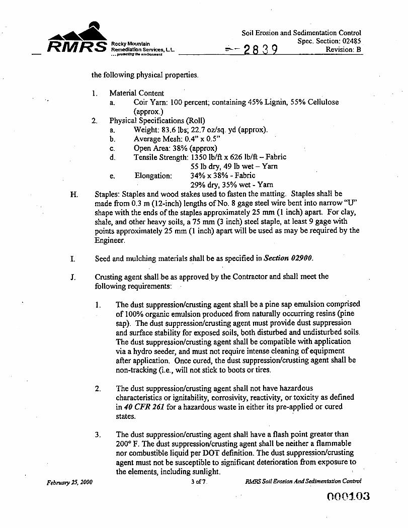
H.
I.
J.
Rocky Mountain Remediation Services, . . . prnruthg (h. *mlmnnent
LL
Soil Erosion and Sedimentation Control Spec. Section: 02485 8 3 9 Revision: B 5’-
the following physical properties.
1. Material Content a. Coir Yam: 100 percent; containing 45% Lignin, 55% Cellulose
(aPProx*) 2. Physical Specifications (Roll)
a. Weight: 83.6 lbs; 22.7 odsq. yd (approx). b. Average Mesh: 0.4” x OS” c. Open Area: 38% (approx) d. Tensile Strength: 1350 lb/ft x 626 lb/ft - Fabric
e. Elongation: 34% x 38% - Fabric 55 lb dry, 49 lb wet - Yarn
29% dry, 35% wet - Yam Staples: Staples and wood stakes used to fasten the matting. Staples shall be made from 0.3 m (12-inch) lengths of No. 8 gage steel wire bent into narrow “U” shape with the ends of the staples approximately 25 mm (1 inch) apart. For clay, shale, and other heavy soils, a 75 mm (3 inch) steel staple, at least 9 gage with points approximately 25 mm (1 inch) apart will be used as may be required by the Engineer.
Seed and mulching materials shall be as specified in Section 02900.
Crusting agent shall be as approved by the Contractor and shall meet the following requirements:
1. The dust suppressiodcrusting agent shall be a pine sap emulsion comprised of 100% organic emulsion produced from naturally occurring resins (pine sap). The dust suppressiodcrusting agent must provide dust suppression and surface stability for exposed soils, both disturbed and undisturbed soils. The dust suppressiodcrusting agent shall be compatible with application via a hydro seeder, and must not require intense cleaning of equipment after application. Once cured, the dust suppressiodcrusting agent shall be non-tracking (Le., will not stick to boots or tires.
2. The dust suppressiodcrusting agent shall not have hazardous characteristics or ignitability, corrosivity, reactivity, or toxicity as defined in 40 CFR 261 for a hazardous waste in either its pre-applied or cured states.
3. The dust suppressiodcrusting agent shall have a flash point greater than 200” F. The dust suppressiodcrusting agent shall be neither a flammable nor combustible liquid per DOT definition. The dust suppressiodcrusting agent must not be susceptible to significant deterioration from exposure to the elements, including sunlight.
RMRS Soil Erosion AndSedimentation Conhol
00Qa-83
Soil Erosion and Sedimentation Control Spec. Section: 02485
+- 2 8 3 9 Revision: B Rocky Mountain Remediation Services, LL - RMRS . . . pmtuthg Ih. *nv lmm~nl
4. Seeding shall be in accordance with Section 02900.
Similar products may be substituted with the Contractor’s prior approval. See ACR-001 for all submittal general requirements and procedures.
PART 3 EXECUTION
3.1 FIELD CONDITIONS
A. Silt Fences
1
2 3
4
5
6
Install in accordance with ODNR and manufacturer’s recommendations. Place at locations shown on drawings prior to start of earthwork. Silt fence shall be constructed before up slope land disturbance begins. All silt fence shall be placed as close to the contour as possible so that water will not concentrate as low points in the fence and so that small swalles or depressions which may carry small concentrated flows to the silt fence are dissipated along its lengths. To prevent water ponded by the silt fence from flowing around the ends, each end shall be constructed up slope so that the ends are at a higher elevation. The minimum height of the silt fence shall be a 16 inches above the original ground surface. Seams between section of silt fence shall be overlapped with the end staked of each section wrapped together before driving into the ground.
B. Erosion Control Blankets (Matting) ’
1. Install in accordance with ODNR and manufacturer’s recommendations. All blankets shall be properly anchored with wire staples and wood stakes in patterns and sizes recommended by manufacturer. Bury edges in 6 inches deep trench, rake area smooth, and seed.
2. Erosion control blanket shall be used on all slopes steeper than 4H: 1V and at all ditch inverts, to a ditch depth of 1 foot.
C. CheckDam 1.
2.
The check dam shall be constructed of 4-8 inch diameter stone, place so that it completely covers the width of the channel. The top of the check dam shall be constructed so that the center is approximately 6 inches lower than the outer edges, so water will flow across the center and not around the ends. The maximum height of the check dam at the center of the weir shall not 3.
Febtuary 25,2000 4 of7 RMRS Soil Ervsion And Sedimentation Control
OQP_d.O4
Rocky Mountain Remediatiion Services, LL
*a& RMRS
Soil Erosion and Sedimentation Control - 2 8 3 9 Spec. Section: 02485
Revision: B - . . . pmBcUng Um * m h n m m f
exceed 3 feet. Spacing between dams shall be as shown on the drawings or as directed by the Contractor.
4.
D. Dumped Rock Fill
1. Place and maintain dumped rock fill material for rock channel protection as indicated on the Contract Drawings and in accordance with ODOT Item 61 0.07 and 601.08.
E. Crusting Agent
1. The material shall be applied at the rate recommended by the manufacturer or as directed by the Contractor. Reapply as necessary to inhibit erosion and dust.
3.2 ADJUSTING
A. Sediment shall be removed anc temporarily placed onto the bank of the channel, ditch, or trap to dewater and, when necessary, for sampling. Excavation, sampling, and disposal of sediment shall be as specified in Section 02200 and consistent with site regulations and Section 02001 - Site Work General Provisions.
B. Remove accumulated sediment, debris, and obstructions as necessary from the ditches and the channels as directed by the Contractor. In no case shall sediment reduce the available depth in the ditches and channels to less than one-third the depth shown on the Construction Drawings.
C. Remove accumulated sediment from the sediment trap before available depth is reduced to one-half its designed depth.
D. Removal of Temporary Erosion Control Facilities.
1. Erosion control facilities shall be removed at the direction of the Contractor after the disturbed areas are stabilized and established with grass or other measures approved by the Contractor.
3.3 GENERAL
Febmty 25,2000 5 of7 RMRS Soil Erosion And Sedimentntion Control
420Q3-05
Soil Erosion and Sedimentation Control Rocky Mountain - 2 8 3 9 Spec. Section: 02485
Revision: B - RMRS Remediatiion Services, LL ... pm*cclnpch.*rnhnm~nc
A. Limiting Surface Erosion: The Contractor has the authority to limit the surface area of erodible material exposed by clearing and grubbing, and to direct immediate permanent or temporary sediment control measures to prevent the transport of sediment. This includes, but is not limited to, the construction of berms, dikes, dams, ditches, sediment collection pits or basins, and the use of temporary seeding, mulches, matting, stone, riprap or other control devices as necessary to control erosion and the transport of sediment.
B. Timing for Installation of Sediment Control Devices: The Subcontractor shall install all necessary sediment control devices prior to the start of any land disturbance. Soil erosion and sediment control facilities shall be adapted andor expanded as construction proceeds to meet the requirements specified herein.
C. Restrictions on Pumping of Silt Laden Water: Sediment-laden water shall not be pumped from trenches or excavations into surface waters, streams, wetlands, or natural or man-made channels leading thereto. Sediment-laden water shall be discharged into settling basins located away from water courses so that only clear water enters the water course after the silt has settled out in the settling basin.
D. Stockpiling of Excavated Soil: Excavated soil shall not be stockpiled adjacent to water courses in a manner that will cause sedimentation of the water course.
3.4 CONTROL OF WATER
A. The Subcontractor shall maintain and operate adequate surface and subsurface drainage methods approved by the Contractor to keep the construction site dry, side slopes and bottom of excavations stable, and away from temporary stockpiles so as to prevent the saturation and degradation of the areas in accordance with this Specification and to the satisfaction of the Contractor. Surface water shall be controlled so that the stability of excavated and constructed slopes or bottom is not adversely affected by water, erosion is prevented, and flooding of excavations or damage to structures does not occur. Surface and rain water must be intercepted and drained away from excavations. Surface water shall not pond on subgrades, in excavations or on stockpiles.
Februaty ZS, 2000 6of7 RMRT Soil Erosion AndSedimentation Conttvl
O O Q l Q 6
Soil Erosion and Sedimentation Control Rocky Mountain 2 8 3 9 Spec. Section: 02485
Revision: B - RMRS Remediation Services, LL . . . prokCun0 me embwmenc
3.5 APPLICATION OF VEGETATIVE LAYER SOIL AND SEEDING
A. The Subcontractor shall apply vegetative layer soil and seeding during temporary soil erosion and sedimentation control, and as part of the final cover in accordance with Section 02900 - Seeding. The Subcontractor shall keep seeded areas mowed and in good condition, reseeding all seeded areas if and when necessary until a good, healthy, uniform growth is established over the entire area seeded, and shall maintain all seeded areas in an approved condition until final acceptance. When newly graded subgrade areas cannot be covered with vegetative layer soil and seeded because of season or weather conditions and will remain exposed for more than 30 days, the Subcontractor shall protect those areas against erosion and washouts by whatever means necessary such as straw applied with a hydromulch overspray, wood chips or by other contractor-approved measures. Prior to application of topsoil, any such materials applied for erosion control shall be thoroughly incorporated into the subgrade by discing. Vegetative layer soil containing excessive moisture, frost or in otherwise unworkable condition shall be stockpiled until it is suitable for spreading. Vegetative layer soil shall be placed on all non-paved disturbed areas and spread to a finished thickness as specified using equipment which will avoid excessive compaction. Vegetative layer soil required for temporary soil erosion control shall be placed and spread to a finished thickness of 4 inches. After vegetative layer soil has been spread, all large stiff clods, rocks, roots or other foreign matter shall be cleared and disposed of, as specified or approved, so that the finished surface will be acceptable for subsequent seeding.
3.6 FINAL ACCEPTANCE
A. The Subcontractor shall care for the seeded areas including keeping the grass cut until final acceptance by the Contractor as specified in Section 02900 - Seeding. Acceptance of the seeded areas will be based upon a satisfactory stand of grass. At any time prior to acceptance of work performed by the Subcontractor, areas which have been seeded which fail for any reason to produce a satisfactory growth of grass after a suitable period of time has elapsed shall be regraded (if necessary), fertilized and reseeded in the same manner as specified for the original work at the direction of the Contractor. Grading, seeding and fertilizing areas which fail to produce a satisfactory growth of grass shall be replaced at the expense of the Subcontractor.
END OF SECTION
7of7 RMRS Soil Erosion And Sedimentation Control
O O W _ Q 7
No. of Pages
9 Section No.
Date Description 1
2/25/00 Seeding Q-Le ve I RMRS Specification No. (if applicable)
B I MK I D. Kalenits I
02900 Revision
SPC N/A Originating Co. Originator
Project Engineer
Lead Project Engineer
0 Verifier
0 0
Quality Assurance Lead
Construction Manager
Safety Basis Lead
Health and Safety Manager
0 Project Manager
Seeding Spec . Section: 02900
8 3-9 Revision: B I?L- Rocky Mountain Remediation Services . LLC.
pmaclfng Ih. envlmnmenr
A& & - RMRS ...
SECTION 02900
SEEDING
TABLE OF CONTENTS
PART 1 GENERAL ............................................................... : ................................................. 1 1 .1 SECTION INCLUDES .................................................................................................. 1 1.2 RELATED SECTIONS AND PLANS ........................................................................... 1 1.3 REFERENCES .............................................................................................................. 1 1.4 SUBMITTALS .............................................................................................................. 2 1.5 DELIVERY, STORAGE, AND HANDLING ................................................................ 3 1.6 HEALTH AND SAFETY REQUIREMENTS ............................................................... 3
PART 2 PRODUCTS ................. ............................................................................................. -3 2.1 MATERIALS ................................................................................................................. 3 2.2 EQUIPMENT ................................................................................................................ 5
PART 3 EXECUTION ........................................................................................ .. ................... 5 3.1 GENERAL ..... 1 ................................................................................................................ 5 3.2 APPLICATION ............................................................................................................. 6 3.3 MAINTENANCE ...................................................................................... ; ................... 8 3.4 WARRANTY ............................................... ~ ................................................................ 8 3.5 ACCEPTANCE ............................................................................................................. 8
. February 25. 2000 i
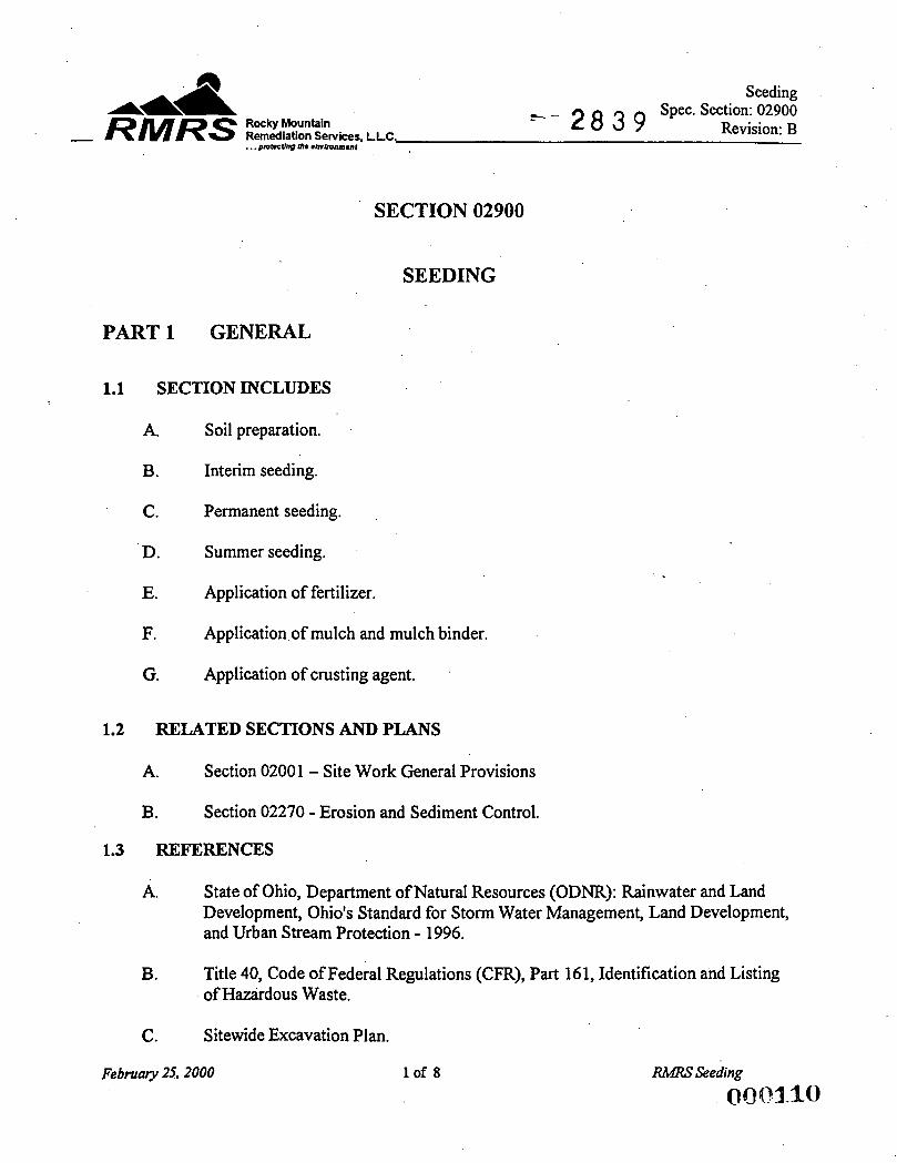
Seeding Spec. Section: 02900
- RMRS Rocky Remediation Mountain Services, LLC. - 2 8 3 9 Revision: B . . . pmncUng me embvnmenf
SECTION 02900
SEEDING
BART1 GENERAL
1.1 SECTION INCLUDES
A. Soil preparation.
B. Interim seeding.
C. Permanent seeding.
D. Summer seeding. .
E. Application of fertilizer.
F. Application of mulch and mulch binder.
G. Application of crusting agent.
1.2 RELATED SECTIONS AND PLANS
A. Section 02001 - Site Work General Provisions
B. Section 02270 - Erosion and Sediment Control.
1.3 REFERENCES
A. State of Ohio, Department of Natural Resources (ODNR): Rainwater and Land Development, Ohio's Standard for Storm Water Management, Land Development, and Urban Stream Protection - 1996.
B. Title 40, Code of Federal Regulations (CFR), Part 161, Identification and Listing of Hazirdous Waste.
C. Sitewide Excavation Plan.
February 25,2000 1 of 8 RMRS Seeding 0003.10
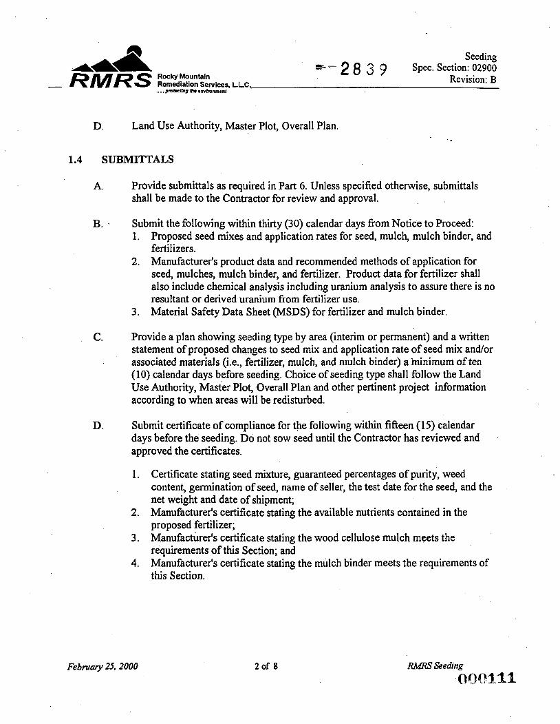
Seeding Spec. Section: 02900
Rocky Mountain Revision: B Remediation Services, LLC,
S- 2 8 3 9 A& & RMRS . . . PrnbcUrm Ih. rnvlmnmenf
-
D. Land Use Authority, Master Plot, Overall Plan.
1.4 SUBMITTALS
A. Provide submittals as required in Part 6. Unless specified otherwise, submittals shall be made to the Contractor for review and approval.
B. . Submit the following within thirty (30) calendar days from Notice to Proceed: 1. Proposed seed mixes and application rates for seed, mulch, mulch binder, and
fertilizers. 2. Manufacturer's product data and recommended methods of application for
seed, mulches, mulch binder, and fertilizer. Product data for fertilizer shall also include chemical analysis including uranium analysis to assure there is no resultant or derived uranium from fertilizer use. Material Safety Data Sheet (MSDS) for fertilizer and mulch binder. 3.
C. Provide a plan showing seeding type by area (interim or permanent) and a written statement of proposed changes to seed mix and application rate of seed mix and/or associated materials (i.e., fertilizer, mulch, and mulch binder) a ininimum of ten (10) calendar days before seeding. Choice of seeding type shall follow the Land Use Authority, Master Plot, Overall Plan and other pertinent project information according to when areas will be redisturbed.
D. Submit certificate of compliance for the following within fifteen (15) calendar days before the seeding. Do not sow seed until the Contractor has reviewed and approved the certificates.
1. Certificate stating seed mixture, guaranteed percentages of purity, weed content, germination of seed, name of seller, the test date for the seed, and the net weight and date of shipment; Manufacturer's certificate stating the available nutrients contained in the proposed fertilizer; Manufacturer's certificate stating the wood cellulose mulch meets the requirements of this Section; and Manufacturer's certificate stating the mulch binder meets the requirements of this Section.
2.
3.
4.
Februaty 25.2000 20f 8 RMRS Seeding [email protected]
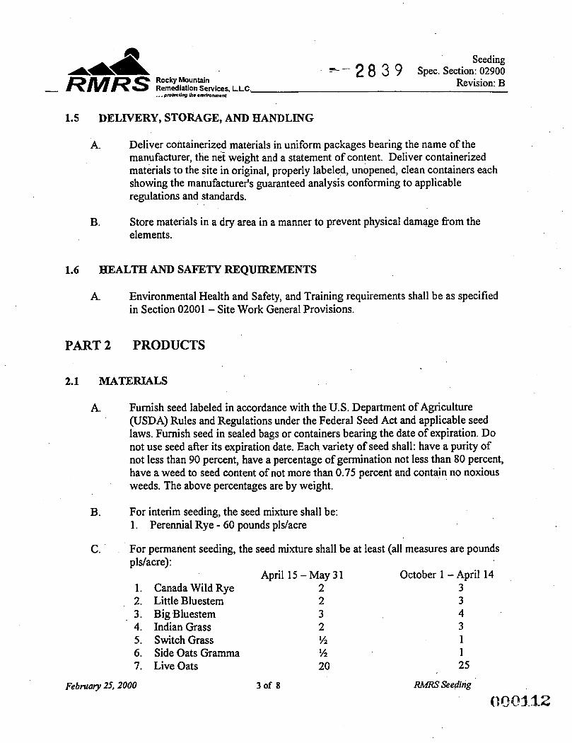
Seeding Spec. Section: 02900
Revision: B 5- 2 8 3 9
Rocky Mountain Remediation Services, LLC,
44 & . . . proMUw #I* rmlmnnr*nf
- RMRS 1.5 DELIVERY, STORAGE, AND HANDLING
A. Deliver containerized materials in uniform packages bearing the name of the manufacturer, the ne? weight and a statement of content. Deliver containerized materials to the site in original, properly labeled, unopened, clean containers each showing the manufacturer's guaranteed analysis conforming to applicable regulations and standards.
Store materials in a dry area in a manner to prevent physical damage from the elements.
B.
1.6 HEALTH AND SAFETY REQUlREMENTS
A. Environmental Health and Safety, and Training requirements shall be as specified in Section 02001 - Site Work General Provisions.
PART 2 PRODUCTS
2.1 MATERIALS
A. Furnish seed labeled in accordance with the U.S. Department of Agriculture (USDA) Rules and Regulations under the Federal Seed Act and applicable seed laws. Furnish seed in sealed bags or containers bearing the date of expiration. Do not use seed after its expiration date. Each variety of seed shall: have a purity of not less than 90 percent, have a percentage of germination not less than 80 percent, have a weed to seed content of not more than 0.75 percent and contain no noxious weeds. The above percentages are by weight.
B. For interim seeding, the seed mixture shall be: 1. Perennial Rye - 60 pounds pls/acre
C. For permanent seeding, the seed mixture shall be at least (all measures are pounds pldacre):
April 15-May31 1. Canada Wild Rye 2 3 2. Little Bluestem 2 3 3. Big Bluestem 3 4 4. Indian Grass 2 3 5 . Switch Grass !4 1 6. Side Oats Gramma % 1 7. LiveOats 20 25
October 1 -April 14
February 25,2000 3of 8
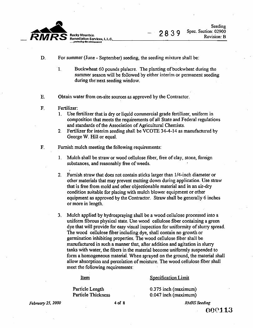
Seeding - 2 8 3 9 Spec. Section: 02900
Revision: B Rocky Mountain Remediation Services, LLc, . . . pmklbrg Ih. environment
- RMRS
D. For summer (June - September) seeding, the seeding mixture shall be:
1. Buckwheat 60 pounds pldacre. The planting of buckwheat during the summer season will be followed by either interim or permanent seeding during the-next seeding window.
E. Obtain water fiom on-site sources as approved by the Contractor.
F. Fertilizer: 1. Use fertilizer that is dry or liquid commercial grade fertilizer, uniform in
composition that meets the requirements of all State and Federal regulations and standards of the Association of Agricultural Chemists. Fertilizer for interim seeding shall be VCOTE 34-4-14 as manufactured by George W. Hill or equal.
2.
F. Furnish mulch meeting the following requirements:
1. Mulch shall be straw or wood cellulose fiber, fiee of clay, stone, foreign substances, and reasonably fiee of weeds.
Furnish straw that does not contain sticks larger than 1/4-inch diameter or other materials that may prevent matting down during application. Use straw that is free fiom mold and other objectionable material and in an air-dry condition suitable for placing with mulch blower equipment or other equipment as approved by the Contractor. Straw shall be generally 6 inches or more in length.
I
2.
3. Mulch applied by hydrospraying shall be a wood cellulose processed into a uniform fibrous physical state. Use wood cellulose fiber containing a green dye that will provide for easy visual inspection for uniformity of slurry spread. The wood cellulose fiber including dye, shall contain no growth or germination inhibiting properties. The wood cellulose fiber shall be manufactured in such a manner that, after addition and agitation in slurry tanks with water, the fibers in the material become uniformly suspended to form a homogeneous material. When sprayed on the ground, the material shall allow absorption and percolation of moisture. The wood cellulose fiber shall meet the following requirements:
Item Specification Limit
Particle Length 0.375 inch (maximum) Particle Thickness 0.047 inch (maximum)
Febnraty 25,2000 4of 8 RMRT Seeding
OQQ1.13
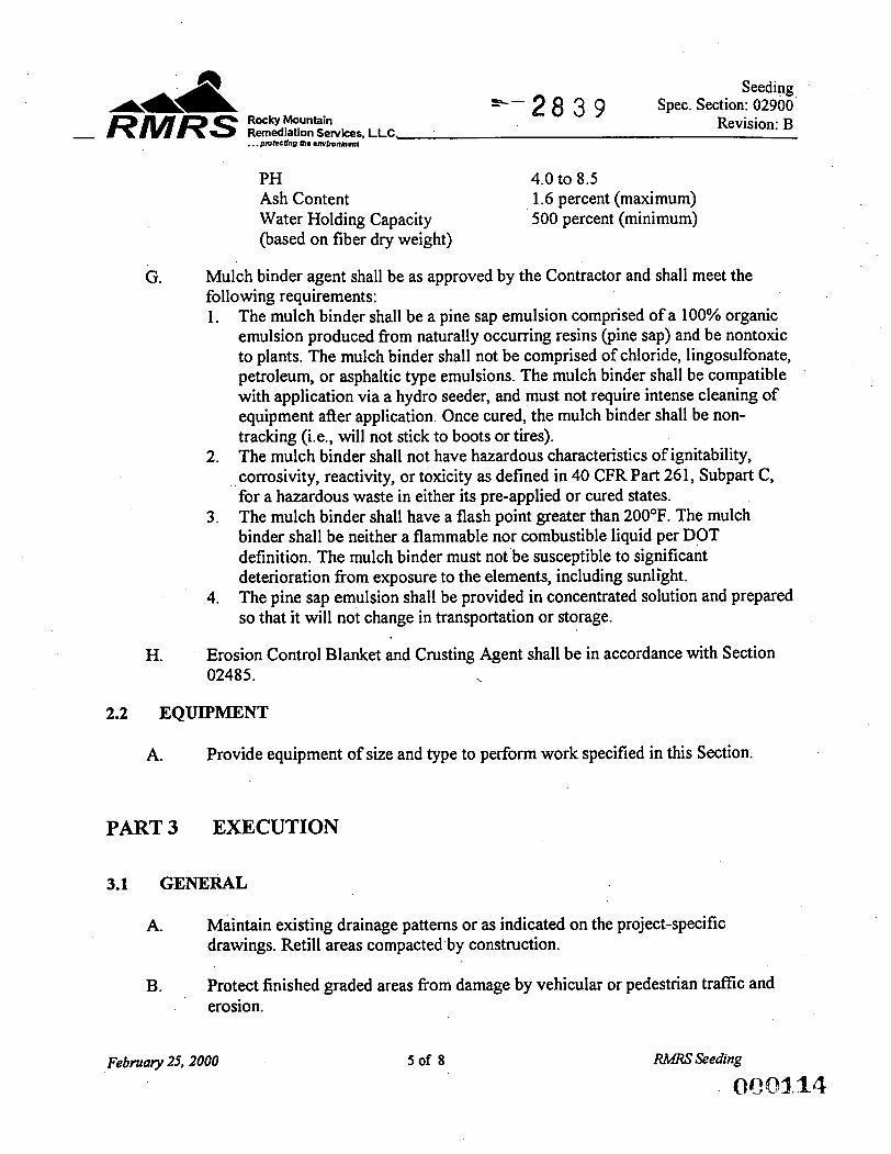
Seeding Spec. Section: 02900
Revision: B ' - 2 8 3 9 Rocky Mountain
Remediation Services, LLC, . . . pmfecUnn 81. mvlmnmmt
A 4 & - RMRS
PH 4.0 to 8.5 Ash Content 1.6 percent (maximum) Water Holding Capacity 500 percent (minimum) (based on fiber dry weight)
G. Mulch binder agent shall be as approved by the Contractor and shall meet the following requirements: 1. The mulch binder shall be a pine sap emulsion comprised of a 100% organic
emulsion produced fiom naturally occurring resins (pine sap) and be nontoxic to plants. The mulch binder shall not be comprised of chloride, lingosulfonate, petroleum, or asphaltic type emulsions. The mulch binder shall be compatible with application via a hydro seeder, and must not require intense cleaning of equipment after application. Once cured, the mulch binder shall be non- tracking (i.e., will not stick to boots or tires). The mulch binder shall not have hazardous characteristics of ignitability, corrosivity, reactivity, or toxicity as defined in 40 CFR Part 261, Subpart C, for a hazardous waste in either its pre-applied or cured states. The mulch binder shall have a flash point greater than ZOOOF. The mulch binder shall be neither a flammable nor combustible liquid per DOT definition. The mulch binder must not be susceptible to significant deterioration fiom exposure to the elements, including sunlight. The pine sap emulsion shall be provided in concentrated solution and prepared so that it will not change in transportation or storage.
2.
3.
4.
H. Erosion Control Blanket and Crusting Agent shall be in accordance with Section 02485. h
2.2 EQUIPMENT
A. Provide equipment of size and type to perform work specified in this Section.
PART 3 EXECUTION
3.1 GENERAL
A. Maintain existing drainage patterns or as indicated on the project-specific drawings. Retill areas compacted by construction.
Protect finished graded areas fiom damage by vehicular or pedestrian traffic and erosion.
B.
February 25,2000 5of 8 RMRS Seeding
(tQzo3.14
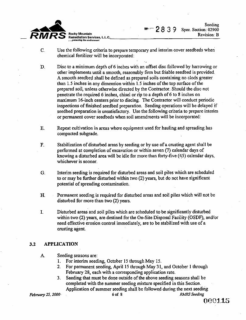
Seeding Spec. Section: 02900
Rocky Mountain Revision: B Remediation Services, LLC,
*- 2 8 3 9 . . . pmIecUng (h. wwhnment
44 & - RMRS
C. Use the following criteria to prepare temporary and interim cover seedbeds when chemical fertilizer will be incorporated:
Disc to a minimum depth of 6 inches with an offset disc followed by harrowing or other implements until a smooth, reasonably firm but friable seedbed is provided. A smooth seedbed shall be defined as prepared soils containing no clods greater than 1.5 inches in any dimension within 1.5 inches of the top surface of the prepared soil, unless otherwise directed by the Contractor. Should the disc not penetrate the required 6 inches, chisel or rip to a depth of 6 to 8 inches on maximum 16-inch centers prior to discing. The Contractor will conduct periodic inspections of finished seedbed preparation. Seeding operations will be delayed if seedbed preparation is unsatisfactory. Use the following criteria to prepare interim or permanent cover seedbeds when soil amendments will be incorporated:
D.
E. Repeat cultivation in areas where equipment used for hauling and spreading has compacted subgrade.
F. Stabilization of disturbed areas by seeding or by use of a crusting agent shall be performed at completion of excavation or within seven (7) calendar days of knowing a disturbed area will be idle for more than forty-five (45) calendar days, whichever is sooner.
G. Interim seeding is required for disturbed areas and soil piles which are scheduled to or may be fbrther disturbed within two (2) years, but do not have significant potential of spreading contamination.
H. Permanent seeding is required for disturbed areas and soil piles which will not be disturbed for more than two (2) years.
I. Disturbed areas and soil piles which are scheduled to be significantly disturbed within two (2) years, are destined for the On-Site Disposal Facility (OSDF), and/or need effective erosion control immediately, are to be stabilized with use of a crusting agent.
3.2 APPLICATION
A. Seeding seasons are: 1. 2.
3.
For interim seeding, October 15 through May 15. For permanent seeding, April 15 through May 3 1, and October 1 through February 28, each with a corresponding application rate. Seeding that must be done outside of the above seeding seasons shall be completed with the summer seeding mixture specified in this Section. Application of summer seeding shall be followed during the next seeding
Febmary 25, 2000. 6of 8 RMRS Seeding
OQoa.15;
Seeding Spec. Section: 02900
Rocky Mountain Revision: B
_e-- 2 8 3 9 Remediation Services, LLC. . . . pmbchp a m h n m m t
- RMRS
B.
C.
D.
E.
F.
G.
season by the application of either interim or permanent seeding, as appropriate, in accordance with the general execution requirements specified in this Section.
Apply fertilizer, seed, mulch, and mulch binder to disturbed areas and areas excavated and graded in this Contract requiring seeding unless otherwise indicated or directed by the Contractor. All seeding seasons and all application rates for seed and related materials are subject to adjustment as directed or approved by the Contractor.
Application of Fertilizer: 1. 2.
Sequence of application of seeding mixture, mulch and mulch binder. 1.
Apply fertilizer at a uniform rate of 1 pound per 1000 square feet. Disc fertilizer thoroughly into upper 6 inches.
Apply seed mixture at the minimum rate as specified in this Section. Seeding shall be done by hydroseeding, broadcasting, or by drilling to a depth of 1/4 inch followed by cultipacking. When hydroseeding, the mixture tank shall be cleaned prior to use to ensure remnant seed is not introduced to the proposed seed mixture. Do not seed areas in excess of that which can be mulched within 24 hours. Apply mulch within 24 hours of seeding. Spread straw mulch in a uniformly thick layer. Apply water with a fine spray immediately after each area has been straw mulched. Wet soil at approximately a rate of 120 gallons per 1,000 square feet. Apply mulch binder at the rate specified in this Section.
2. 3. 4. 5.
6.
Spread straw mulch, either by hand or by blowing method, at the rate of 2 air-dried tons per acre. During June through September, increase straw mulch application rate to 3 air-dried tons per acre. Application of straw mulch by the blowing method is exempt from the dust control requirements.
Apply sprayed wood cellulose fiber at a net dry weight of 2,000 pounds per acre. Mix the wood cellulose fiber with water at a ratio of 50 pounds of wood cellulose fiber per 100 gallons of water.
Maintain mulching material in place with a pine sap emulsion binder. Apply mulch binder according to manufacturer's directions. Unless specified otherwise by the manufacturer, dilute concentrated pine sap emulsion to ratio of four (4) parts water to one (1) part concentrate. Apply diluted pine emulsion at a rate of 2,500 gallons per acre.
February 25,2000 7of 8
Seeding Spec. Section: 02900
ROCW muiiain k-28 3 9 Revision: B Remediation Services, LLC,
44 & . . . PmkanO Ih. *mbunment
- RMRS 3.3 MAINTENANCE
A. Maintain the seeded areas in satisfactory condition until acceptance of the seeding by the Contractor. Maintenance of the seeded areas includes repairing eroded areas, revegetating when necessary, watering and mowing (if applicable). A satisfactory condition of the vegetated area is defined as follows: 1. 2.
3.
An area shall have a predominant stand of the seeded vegetation. Within 3 weeks, germination must occur over 95 percent of the area with no single bare area greater than 3 square feet. Within 3 months, 95 percent of the area must be covered with mature vegetation.
B. Areas that fail to meet these requirements shall be repaired or reseeded as necessary to produce an acceptable stand of vegetation, as specified in this Section. Areas that become bare during June through September shall be reseeded with the summer seeding mix specified in this Section.
C. Maintain areas applied with a crusting agent to ensure proper erosion control. The crusting agent shall be reapplied to eroded and bare areas as necessary.
3.4 WARRANTY
A. Seeded areas shall be subject to a warranty period of not less than 12 months fiom initial establishment of vegetation over 100 percent of the seeded areas.
B. At the end of the warranty period, the Contractor will perform an inspection upon written request by the Subcontractor. Seeded areas not demonstrating satisfactory condition of vegetation as specified herein, shall be repaired, reseeded and maintained to meet all requirements as specified herein at the Subcontractor's expense.
3.5 ACCEPTANCE
A. The seeded areas shall be accepted at the end of the warranty period if a satisfactory condition exists as defined in this Section.
B. After all disturbed areas are stabilized and all necessary corrective work has been completed, the Contractor will certify in writing the final acceptance of the seeded areas.
February 25,2000
END OF SECTION 8of 8
1 2 3 4 5 6 7 8 9
10 l i 12
13
14
15
ATTACHMENT D
RUBB Building Manufacturer’s Data
.. ..:. ,:\ ... ... . .. , 1 . .. 3 % , ,
*
Attachments General Description or the Work February 25,2000
. . . . _. . . : ~-: . .. , . I . . . - .
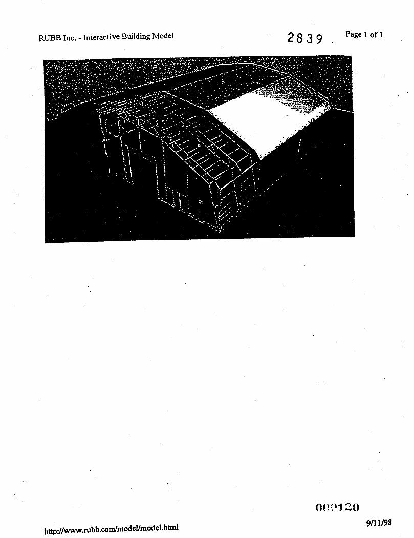
RUBB lnc. - interactive Building Model 2 8 3 9 Page 1 of 1
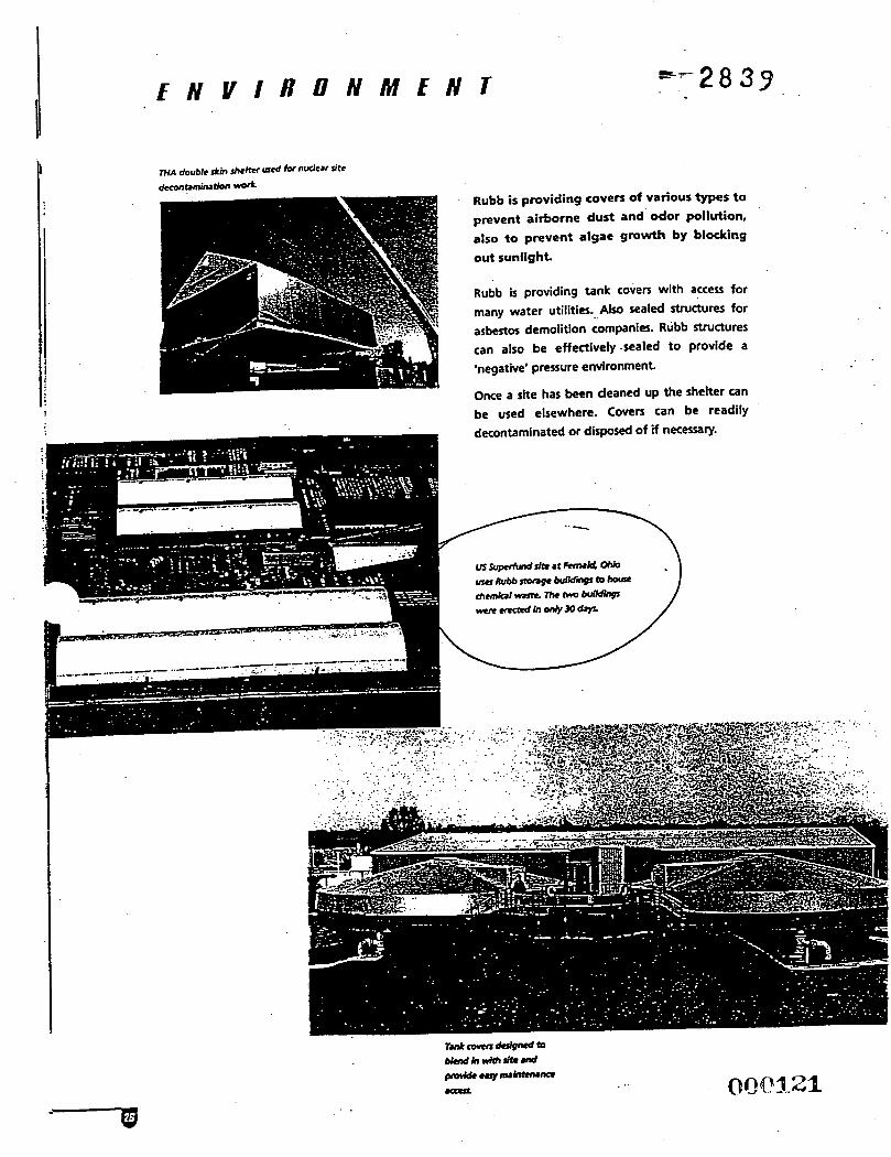
P
E N V I R O N M E N T ' - 2 8 3 9
Rubb is providing covers of various types to
prevent airborne dust and odor pollution, also to prevent algae growth by blocking out sunlight
Rubb is providing tank covers with access for many water utilities. Also sealed structures for asbestos demolition companies. Rubb structures can also be effectively -sealed to provide a 'negative' pressure environment
Once a site has been deaned up the shelter can be used elsewhere. Covers can be readily decontaminated or disposed of if necessary.
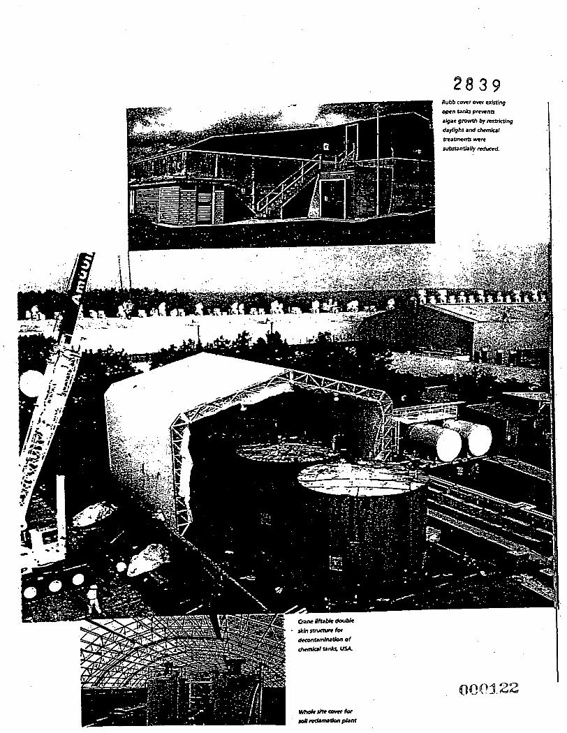
2 8 3 9
t
2 8 3 9

.
3 4 5 6 7 8 9
?'? 11 12 13 14 15 16
February 25.2000 Attach rn e nts General Descr&bon of the Work
ATTACHMENT E
Typical Portable Trailer Data
. . , . ' .
. : . . .". . . . .
. . . .... : . . . ~
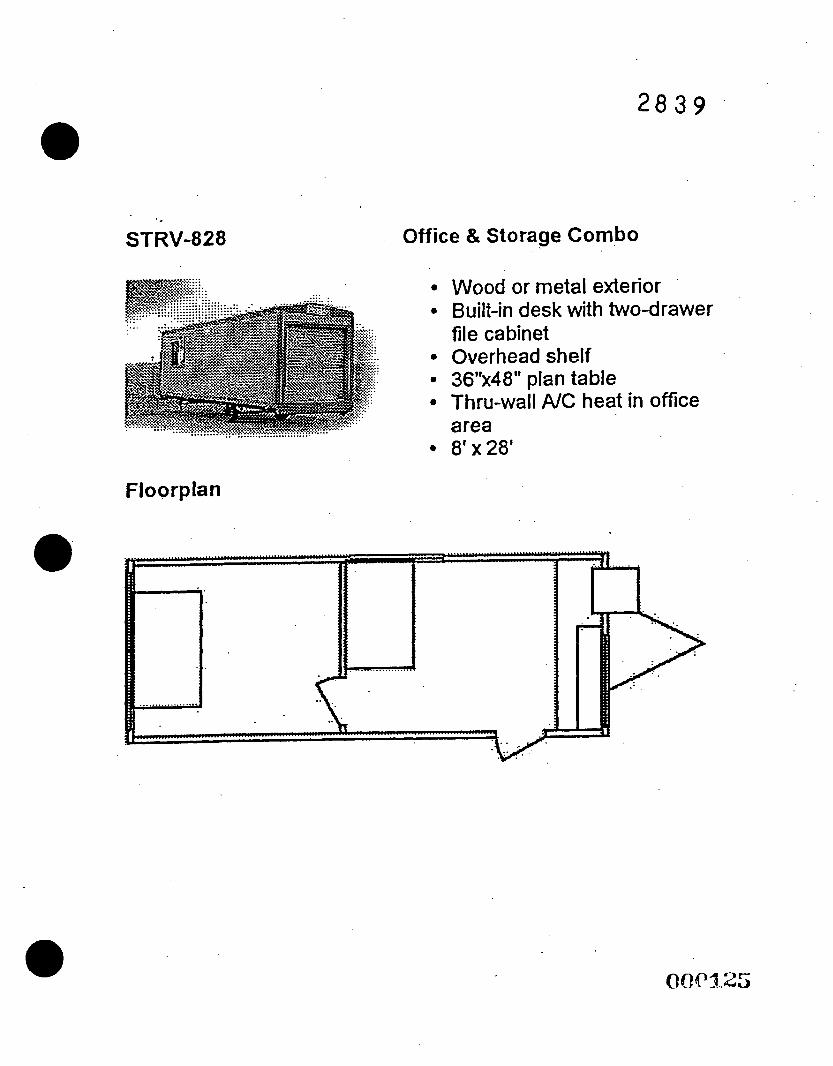
2 8 3 9
STRV-828
Floorplan
Office & Storage Combo
Wood or metal exterior Built-in desk with two-drawer file cabinet Overhead shelf 36"x48" plan table Thru-wall N C heat in ofice area 8' x 28'
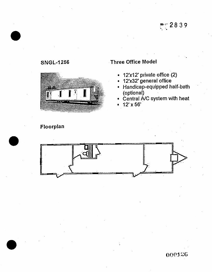
= r 2 8 3 9 - - . -
SNGL-I 256 Three Office Model
?2'xl2' private office (2) 12'x32' general office Handicap-equipped half-bath
Central A/C system with heat 12'x56'
(optional)
Floorplan
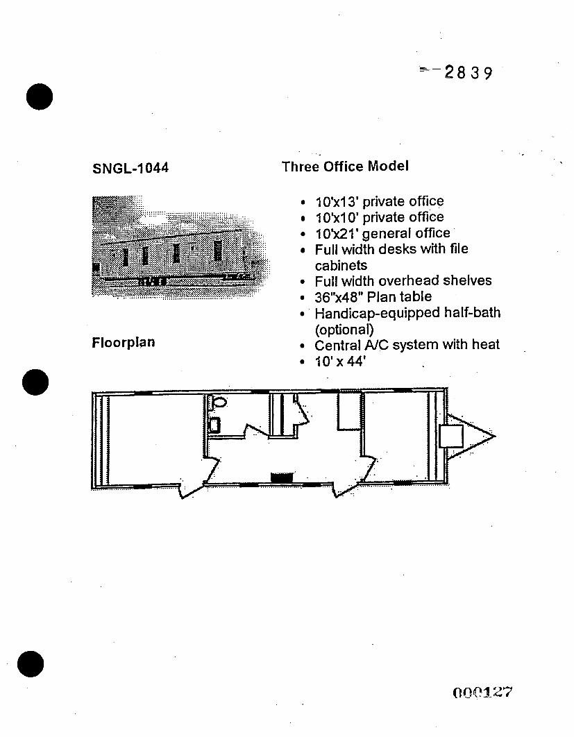
- -28 3 9
SNGL-1044
Floorplan
Three Office Model
1 O'x13' private office 1 O'xl 0' private office IO ' x21 ' general office Full width desks with file cabinets Full width overhead shelves 36"x48" Plan table Handicap-equipped half-bath
Central NC system with heat IO'x44'
(0 ptio na I) .
2 8 3 9
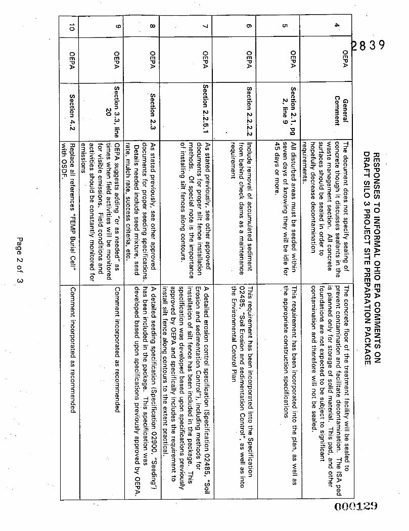
3 3 (D 3
3 ' 0
U
r, -.
4 4 2 (D Q a, v)
;
3 3
0 0
(D 3 Q (D Q
(D
s 3 3 2
4 4
(D
-. 3 0
U
2 Q a, v)
; 0 0
00
0 rn 2
g 2. 0 ' P P c" -L
0 rn 2
I', P P N
P
: 8 3 9
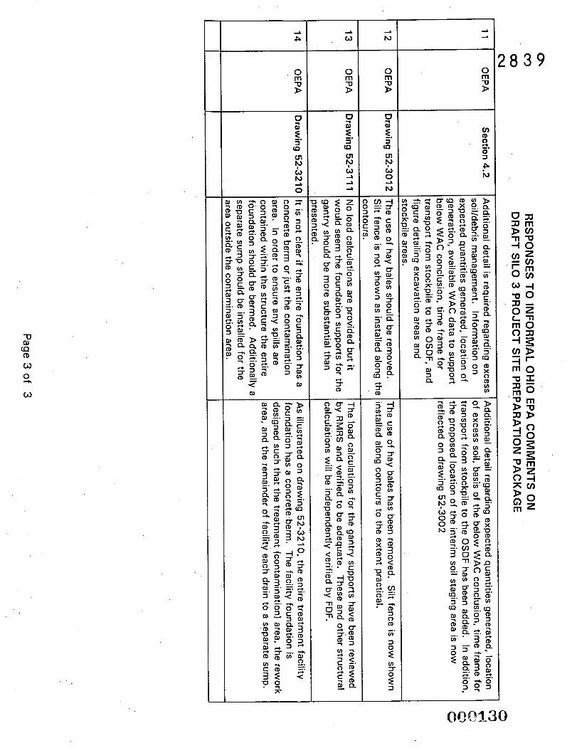
0 rn s
I d
N
0 rn s
5 (D
0 rn s
v)
! 8 3 9
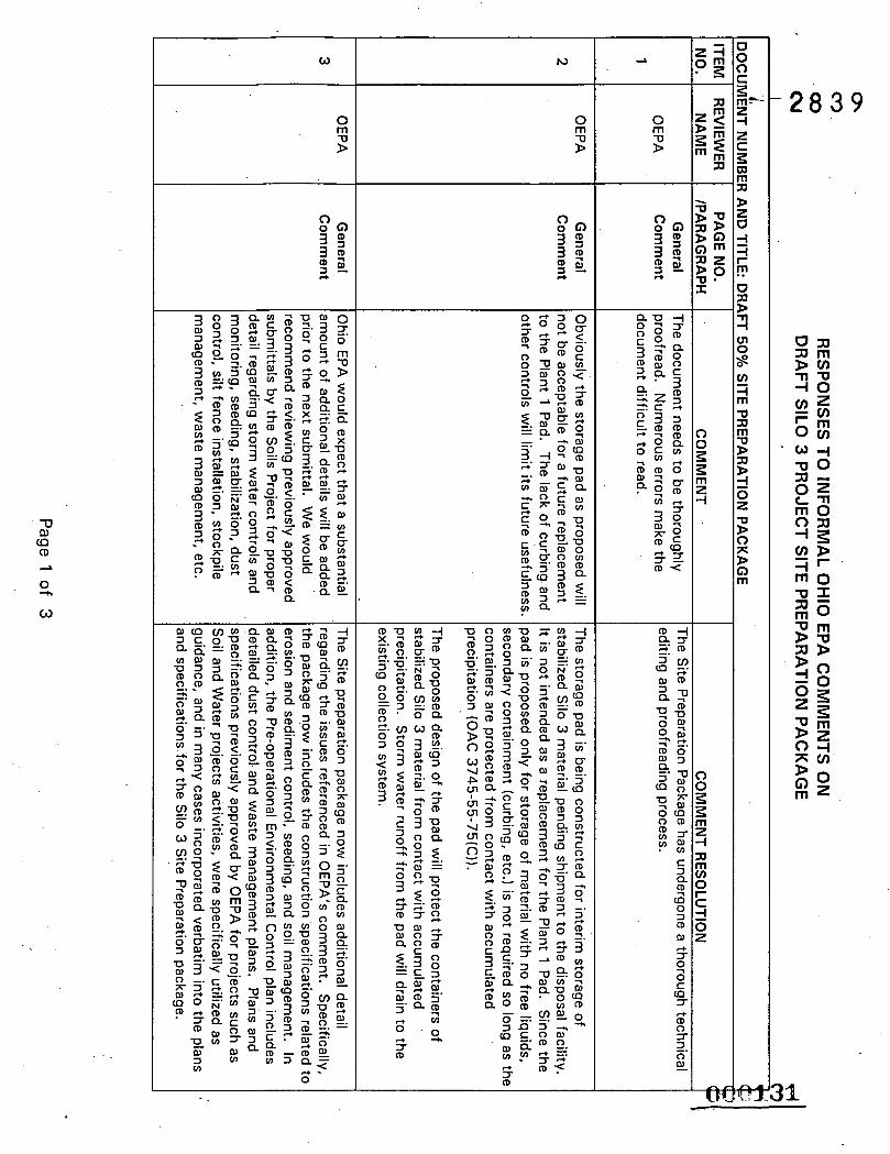
0 rn s
h,
0 rn
C 3 Q
to 0 3 (D
a,
3
e
r,
2 C 0 5
(D 0 5 3 0
r,
-. ar