Embed Size (px)
Citation preview

Fermi lab TM-1334 2791. 000
TESTING OF THE SUPERCONDUCTING SOLENOID FOR THE FERMILAB COLLIDER DETECTOR*
R. W. Fast, C. N. Holmes, R. D. Kephart, J. B. Stoffel, M. E. Stone, R. H. Wands, and T. N. Zimmerman
Fermi National Accelerator Laboratory, Batavia, IL USA
and
K. Kondo, S. Mori, and R. Yoshizaki University of Tsukuba, Sakura, Ibaraki, Japan
and
K. Asano Hitachi Works, Hitachi, Ltd., Hitachi, Ibaraki, Japan
July 1985
*Submitted to Advances in Cryogenic Engineering, Vol. 31., and to be presented at the 1985 Cryogenic Engineering Conference, Cambridge, Massachusetts, September 13, 1985.

TESTING OF THE &JPERCONDUCTING OOLENOID l'UR THE FERMILAB OOLLIDER DETECTOR
ABSTRACT
R. w. Fast, C. N. Holmes, R. D. Kephart, J. B. Stoffel, M. E. Stone, R. H. Wands, and T. N. Zimmerman
Fermi National Accelerator Laboratory Batavia, Illinois
K. Kondo, s. Mori, and R. Yoshizaki
University of Tsukuba Sakura, Ibaraki, Japan
K. Asano
Hitachi Works, Hitachi, Ltd. Hitachi, Ibaraki, Japan
The 3 m + x 5 m long x 1.5 T superconducting solenoid for the Fermilab Collider Detector has been installed at Ferm.lab and was tested in early 1985 with a dedicated refrigeration system. The refrigerator and 5.6-Mg magnet cold mass were cooled to 5 K in 210 hours. After testing at low currents, the magnet was charged to the design current of 5 kA in 5-MJ steps. During a 390 A/min charge a spontaneous quench occurred at 4.5 kA due to insufficient liquid helium flow. Three other quenches ·occurred during "slow" discharges which were nevertheless fast enough to cause high eddy current heating in the outer support cylinder. Quench behavior is well understood and the magnet is now quite reliable.
INTRODUCTION
The Fermilab Collider Detector utilizes a superconducting solenoid 3 m + x 5 m to produce a horizontal magnetic field of 1.5 T, to study pp collisions 1n the Tevatron. To minimize measurement errors for particles passing through the solenoid it is fabricated largely of aluminum and is conduction cooled.
Design details of the CDF solenoid have been presented elsewhere.1 The single-layer coil uses an aluminum-stabilized conductor at an operating _current of 5 kA. The outward radial force is reacted in an aluminum outer support cylinder. The net forces on the coil/support cylinder are carried by Inconel supports. The coil is refrigerated by a flow of twophase helium at -5 K through an aluminum tube welded to the outer support cylinder. The vacuum vessel, fabricated of aluminum, is attached to an iron flux retum yoke .2 A control dewar, located above the cryostat and
1
outside the iron yoke, serves as the interface between the aagnet cryostat and the refrigeration system. The fabrication of the coil, cryostat and control dewar and the initial teat without iron have been described earlier.rs
The refrigeration system6 is based upon the standard Permilab "satellite" refrigerator which has a nominal capacity of 625 W or 125 L/h. Helium of high liquid fraction is circulated through the coil cooling tube using the main compressor to provide the required pressure differential. Two transfer lines permit operation of the magnet in either the Assembly Ball for testing or in the Collision Ball for the experiments. The refrigerator is computer controlled using the same hardware and software as the Tevatron refrigerators. The refrigeration system was tested prior to magnet installation and was found to exceed its nominal capacity.
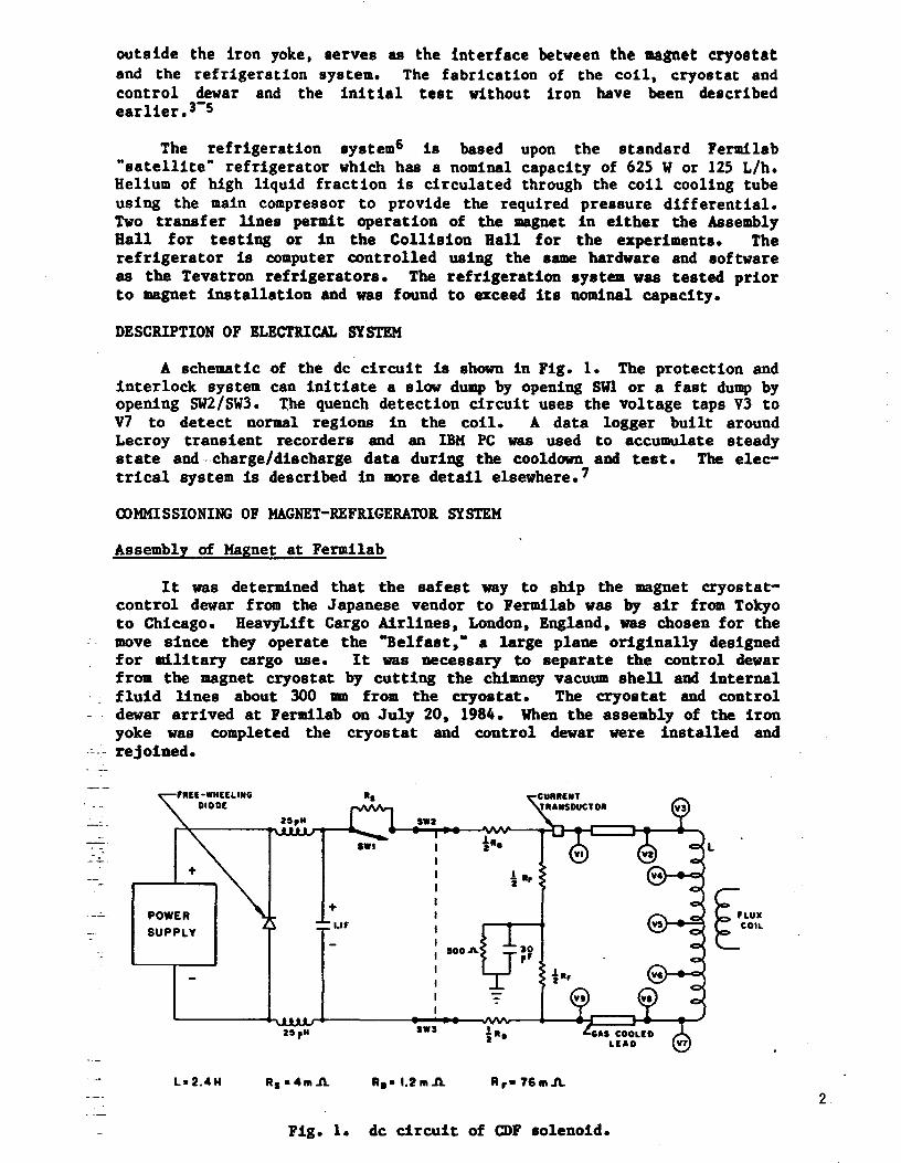
DESCRIPTION OF ELECTRICAL SYSTEM
A schematic of the de circuit is shown in Fig. 1. The protection and interlock system can initiate a slow dump by opening SWl or a fast dump by opening SW2/SW3. the quench detection circuit uses the voltage taps V3 to V7 to detect normal regions in the coil. A data logger built around Lecroy transient recorders and an IBM PC was used to accumulate steady state and--charge/discharge data during the cooldown and test. The electrical system is described in a>re detail elsewhere.7
CX>MMISSIONING OF MAGNET-BEFRIGERA'l'OR SYSTEM
Assembly of Magnet at Fermilab
It was determined that the safest way to ship the magnet cryostatcontrol dewar from the Japanese vendor to Fermilab was by air from Tokyo to Chicago. HeavyLift Cargo Airlines, London, England, was chosen for the move since they operate the '"Belfast,• a large plane originally designed for military cargo use. It was necessary to separate the control dewar from the magnet cryostat by cutting the chimney vacuum shell and internal fluid lines about 300 ID from the cryostat. The cryostat and control dewar arrived at Fermilab on July 20, 1984. Vhen the assembly of the iron yoke was completed the cryostat and control dewar were installed and
.: ~- rejoined.
L• 2.4M
swz
IOOA.
SWJ
Rs •4111.A. R•• 1.2111.A. R,• 76111A
Fig. 1. de circuit of CDF solenoid.
L
~PLUX E_COIL
2

---
-· ----
- : ---- -- .
-- .
Cryogenic Safety Analysis and leview
In order to insure that Fermi.lab employees are protected against the hazards peculiar to cryosystems, Fermilab policy requires that such systems be designed in accordance with written standards and analyzed for cryogenic safety. This policy also requires that the design and safety analysis be reviewed by an independent panel of cryogenic engineers and scientists. The CDF magnet and refrigeration system was designed, safety analyzed, and reviewed in accordance with these requirements.
Hazards of liguid nitrogen and liguid helium systems. The general hazards' associated with cryogenic systems have been treated elsewhere. 8 The primary hazards of the nitrogen-helium cryosysteu found at Fermi.lab are liquid cryogen spray and oxygen deficiency both of which can result from cryogen containment failure. At many of the Fermi.lab installations these hazards are exacerbated by the location of major system components, e.g. superconducting •gnets and liquid transfer lines, in underground tunnels or in below-grade or underground experimental halls. The standard for evaluating the oxygen deficiency hazard (ODB) associated with cryogenic installations is given in the Fermi.lab Safety Manual. g
_ Design of vessels and 1>i1>ing. The Fermilab Safety Manual requires that cryogenic vessels and piping be designed and fabricated in accordance with Section VIII of the ASME Boiler and Pressure Vessel Code and Section B31 of the ASME Code for Pressure Piping. For example, the liquid vessels of the CDF helium and nitrogen storage dewars are Code stamped. Accepted practice at Fermi lab for the vacuum vessels of dewars follows common industrial practice, i.e. a collapse pressure of 0.21 MPa (30 psi). Since the pressure in a cryogenic vessel must not exceed 110% of the pressure rating during relieving, qualitative calculations of the pressure rise in the relief systems were performed. The failure modes for which the relief systems associated with the CDF magnet-refrigerator were analyzed are given in Table 1. The relief devices on the helium system are shown in Fig. 2 with details given in Table 2.
Table 1. Failure Modes Analyzed for CDF Cryogenic Vessels
·- - - --- - --- --Failure Mode Vessel: LIN tank LHe tank, Cryostat 6 Control
LIN shielded Dewar
Inner Vacuum Inner Vacuum LHe LIN Vacuum
Loss of vacuum Gas conduction Yea NA Yes NA Yes Yes NA Air condensation NA NA Yes NA Jes NA NA
Fire or unexpected Yes NA Yea NA Yes No NA source of beat
Operator error Yes HA1 Yea NA Ho No NA
Rupture of LIN NA No Yes Yes Yea NA Yes line in vacuum apace
Rupture of Liie RA NA NA NA Yes NA Yes line ln vacuum space
No1 No2 Rupture of inner vessel NA NA NA NA Yea Quench of coil NA NA
1 NA NA Yes NA Yes
Release of cryopumped NA No NA No2 NA NA Yes air
1 • Relief area . 11.5 x CGA requirement ("Insulated Tank Truck Specification CGA-3111 For Cold Liquefied Gases,• Compressed Gas Assoc., New York (1972).
2. Relief area • 6.5 x CGA requirement. 3

- .
--
TO COMPM'.SSOR SUCTION
10 REFRIGERATOR
FROM REFRIGE ATOR
0.52 MPa ( 75 p 9! EVBP'll--it+--0
t
LHe STORAGE DEWAR
0.17 MPa l2!>psi9l
0,17 MPo 125psiol
SOLENOID
TRANSFER LN: 0.2• M Po ( 35 P•lo)
Fig. 2. Helium system flow schematic.
Assembly Ball· ventilation and ODH analysis. The ventilation system required to prevent an ODH in an enclosed area may be sized by equating the mass flow rate of inerting fluid into the building to the capacity of the ventilation system to remove it. In the CDF Assembly Hall an ODH associated with liquid nitrogen is prevented through use of a fan with a capacity of 3 .8 m3 /s which has an inlet at the lowest level of the ball and an outdoor discharge. The fan is controlled by an oxygen monitor at the low level. The helium ODH is alleviated with roof louvers actuated by an oxygen monitor near the ceiling.
Table 2. Relief Systems for CDF Cryogenic Vessels.
Setting Air C&pacit1 Veaael/Piping Hanuf acturer TJpe MPa (paig) Lia (SCPM)
:
Liii Tanlc
AGC01 lMer Teasel relief TalTe 0.311 (50) 511 (1111.5) lMer Teasel Fike2 burst d1ak 0.110 (58) 675 (11131) Vacuum Teasel parallel plate 0~002 (0.25) 653 (13811)
=-=- ! . - ' Liie Tanlc -- .. ' --- Inner Teasel AGCO relief YalTe 0.52 (75) 3115 (731) -
Inner Yeaael Fike burst diak o.66 (95) 11611 (9811) Vacuum Teasel parallel plate 0.002 (0.25) 156 (330)
-- Cr1oatat and Control Dewar -
He Teasel l piping AGCO relief valYe 0.17 (25) 152 (321) He •easel l piping AGCO relief TalTe 0.17 (25) 152 (321) He Yeaael l piping AGCO relief valve 0.211 (35) 189 (1101) He vessel l piping circle Sea13 relief valve 0.115 (65) 56 (119) He Teasel l piping Fike burst diak 0.52 (75) 378 (800) Yacuwa Teasel parallel plate 0~007 (1) 1109 (2350)
1. Anderaon, Greenwood l Co., Bellaire, TX. 2~ Flke Metal Products Corp~, Blue Springe~ II>. 3. Circle Seal Corp. , Anaheim, Cl.
4

System Cooldown
Cooldown procedure. The helium circuit for the magnet-refrigerator is shown in Fig. 2. During cooldown, flow from the refrigerator passed through the storage dewar, transfer line and magnet cooling circuit and back through the return side of the transfer line. The electrically operated valve EVCP and the manual valve MV-2010 were used to create an imbalance by returning a portion of the flow directly to compressor suet ion. The pressure in the storage dewar was maintained at 0 .17-0 .21 MPa (25-30 psig) by the computer control system, which sensed dewar pressure and regulated EVBP. The control dewar pressure varied with the positions of EVCP and MV-2010, but ranged between 0.04 and 0.08 MPa (6-12 psig) •..
The temperature of the coil/outer support cylinder was monitored with platinum and carbon resistors mounted on the support cylinder at several locations. The temperatures of the supply and return helium flows were measured with similar resistors in the piping.
Cooldown. Cooldown began on the morning of February 28, 1985, when liquid nitrogen flow was started to the precooling beat exchanger of the refrigerator •. A total compressor flow of -40 g/s was established. The helium ..flow -!:hrough .the magnet cooling loop was measured by the venturi flowmeter FIMF as ... 5 g/s. Control valves on the liquid nitrogen shield and intercept circuits were placed under computer control to regulate at 180 K as measured by platinum resistors. The maximum valve positions were limited to keep the cooling rates .low. As cooldown progressed these set temperatures were lowered and the valves allowed to operate over a wider range until full computer control was achieved at the operational set points of 90 K and 80 K for the shield and intercepts, respectively.
The coil reached a temperature of 97 K in 144 hours, at which time the gas expansion engine was started. FIMF indicated a flow of approximately 8 g/s through the magnet at this point. Twenty-four hours later, at a coil temperature of 72 K, the liquid expansion engine was started. The coil resistance, which was continuously monitored during the cooldown, indicated that the coil became superconducting approximately 205 hours into cooldown. The operating temperature was reached 5 hours later. The average cooldown rate was 1.5 K/b. Figure 3 shows the measured coil
..:_-_ temperature as a function of ti11e.
--
Z/ZT 0900
2121 0900
Sii 0900
512 0900
SIS 0900
DATE
S/4 0900
S/5 OIOO
S/6 0900
Fig. 3. Cooldown of magnet-refrigerator system.
SIT S/7 0900 2000 5

With the coil cold, MV-2010 vat completely cloeed to aend all flov back through the refrigerator. Liquid began to accumulate in the storage dewar, and a liquid flow was established through the coil, filling the control dewar. The storage dewar was then filled to about one-half of its 2000-L capacity• and the computer control loop enabled to maintain this liquid level by regulating liquid expansion engine speed. The set point of the storage dewar pressure control loop was set to 0.04 MPa (6 psig). The operation of EVCP, which regulated the control dewar pressure, was placed under computer control at a set point of 0.028 MPa (4 psig). These pressures provided the differential for driving the magnet flow. The flow was also regulated by a control loop which mnitored FIMF and adjusted EVMF accordingly. This flow was set at approximately 10 g/s initially. The system was then stabilized under full computer control to await electrical testing.
Adjustment of supports. Special consideration was given during cooldown to the 24 radial support rods which suspend the coil within the vacuum shell. This is a tension-only support system which relies on the thermal contraction of the coil and support rods during cooldown to provide a preload force. A titanium alloy (6Al-4V) was used for the spherical bearing housings on the rod ends and, as this alloy exhibits very low ductility and fracture toughness at cryogenic temperatures, it was necessary to monitor the rod stress closely and adjust the tension individually if needed. To make this possible, the radial support system had been designed so that the room temperature end of each rod was attached to a tensioning device which penetrated the vacuum shell end rings through a double o-ring seal. This device contained a threaded shaft and nut. Adjusting this nut against the vacuum shell end ring applied tension to the support rod. Calibrated strain gauge washers installed under the nuts provided an accurate, computer mnitored indication of rod tension.
The rods were designed for a maximum force of 7 .9 Mg, corresponding to a total radial decentering force of 25.S Mg. Because certain of the rods bear the cold mass of ... 5 .6 Mg, the preload force varied frm 4 .8 Mg to S.8 Mg. The tensions were adjusted during cooldown to maintain these
_ desired values ±1 Mg.
Magnet Test Procedures and Basic Results
- A series of tests at low current (100 to 1000 A) were performed to __ verify proper operation of the interlock and quench protection systems and
to calibrate and. debug the instrumentation. When this was complete the ___ coil was energized to succeedingly higher currents in 5-HJ steps as shown ~in Table 3. - -· t
Table 3. Summary of Magnet Tests
Storea Current Eneru Tea ta
(kA) (MJ) Performed
1.0 1;5 2.0 2;9 3.5 -~, ';6 s.o
1.2 2.7 11.8
10., 111.7 20.2 25.11 30.0
FD, SD* FD, SD FD !¥• SD B , FD FD, H FD FD, SD
• FJ> • Fut dlachaJ'ge (dump), SD • Slow dlacharge (dump)
t H • Heater teata 6

The coil wae typically charged with the power supply voltage regulating to give a linear ramp ...,z50 A/rain over moat of the charge. When the current in the coil was close to the desired value the power aupply ta switched to a current regulating mode which monitored a current tranaductor located on the coil bus. After the coil reached the current for each step, the magnetic field in the bore, measured with a Hall probe, the electromagnetic forces on the coil supports and the deflections of the yoke and end plug structures were recorded. Then a fast dump was manually initiated. The coil voltages, temperatures and helium circuit pressures resulting from the discharge were studied before proceeding to the next higher step in current. For some current values a slow dump was also manually initiated. For currents less than 2 kA it was deduced that the coil remain superconducting throughout the fast discharge since the observed time constant (30.9 s) was in good agreement with that expected for a superconducting discharge, T • L/Rp • 2.4 B/0.076 Q • 32 s.
Above -3 kA, eddy currents flowing in the outer support cylinder caused the coil to quench during a fast discharge. In this case the coil resistance, in series with R1 , shortens the effective time constant of the discharge as shown . in Table 4, which also g:l ves the maximum temperature reached in the center of the outer support cylinder after each fast discharge. The forces on the supports and deflections of the end wall and
-- plug at...5 -kA are given in Table 5.
Measured Stability - Beater Tests
To study coil stability and quench propagation two heaters are imbedded in holds in the outer support cylinder. One is located at the center of the coil while the other is near one end. Each beater consists of a small spool of resistance ribbon mounted so that it is in good thermal contact with the FRP layer on the outer diameter of the coil yet thermally isolated from the support cylinder. The heater simulates a release of mechanical energy at the support cylinder/PIP boundary. We were unable to
_. quench the coil with a 24-s, 2.7-k.J heater pulse at currents of 3.5 and . . 4 .1 kA. The peak temperature of the outer support cylinder approximately
. 100 mm from the heater was 8.5 K. The thermal time constant for the system to recover from such a temperature excursion was about one minute. An estimate of the energy balance between the obllic heating of a section of normal conductor and the conduction cooling by the outer support -
.-. - cylinder gives an equilibrium temperature of -10 It for this magnet cur_-_-rent. It is possible that a small section of conductor beneath the heater
. does quench, but it recovers by conduction cooling if the magnet current - -
'. -Table 4. Fast Discharge Characteristics
CUrrent (kA)
1.0 1.5 2.0 2~9
3.5 ,_, .11.5 5;0
ltfectlve time
constant (a)
30.9 30~9 30.9 29.JI 28.3 21.0 26.0 19~5
Multaperature
(IC)
1 8
10 21 28 3.11 37 JS5
7

Table 5. 5 kA Deflections and Forces
End Wall Deflection End Plua Deflection Axial Decenterina force Radial Decenterin1 Force
2.5 -5.0 -27 Ml -1 Ml
is sufficiently low. Heater pulses of greater energy.were not applied due to . concern about damaging the !'IP insulation. Heater tests were not attempted at higher excitations.
guench Behavior
On four occassions during •gnet testing and the two months of coil operation for magnetic field mapping and drift chamber testing, the coil
. quenched due to. a. rapid change_ of field and/or by inadequate flow of helium. We believe that we understand the observed quench behavior.
Quench #1 - 4.5 kA guench while charging• This quench occurred when rapidly charging the magnet (390 A/min) with a helium flow rate of 13 g/s. The quench began in the end of the coil that baa both axial and radial supports. - Since_ this end has the higher conduction beat load and since the helium-temperature support intercepts lie at the end of the cooling circuit it is believed that the liquid fraction was sufficiently low that the intercepts were ineffective, causing local hot spots at the support attachments. A plot of the observed voltages across each of the coil quadrants is shown in Fig. 4 for the few seconds before the time Ct • O) that the quench detection circuit activated the dump switches. From t • -0.75 s to t • O, the voltage VCl • V3 - V4 increased by 0.34 V indicating a normal region growing in this quadrant. Similarly since the power supply voltage was maintained at a constant value, VC2 • V4 - VS, VC3 • VS - V6
---VCI • V3- Y4 -·-VC2• V4-Y5 --YC3•V5-W ---VC4•V&-V7
-8.0
-12.0.....__-~ _ __._ _ ___._ _______ :___L _ __. __ ..___ _ _, -1.0 -0-' 0 +~ +LO tl.5 +2.0. +U ~.O
TIME (t)
Fig. 4. Voltages observed across coil quadrants showing quench initiation.
8

and VC4 • V6 - V7 all a how a corresponding drop of 0 .11 V. Our illl t rumeft• tation does not allow us to determine whether the dominant mode of quench propagation was axial from turn to turn or circumferentially along the conductor. (In the testing of a 1 11 + R&D coillO both modes were present.) However, if we assume that the propagation is purely circumferential we can estimate an effective circumferential quench velocity. In the 0.75 s before t • 0 the coil absorbs 15 .2 x 10' A2-s (15 .2 MIITS). Prom the plot of maximum conductor temperature as a function of absorbed energyl l we concluded that the hot spot temperature at t • 0 must have be~~ -~25 K. The measured resistance of the coil per unit length of conductor is 0.17 pQ/m at 10 It and ...0.3 µO/m at 25 K. If we use a value of 0.23 µ0/m as the average conductor resistance in the 10-25 It region then a l~ngt}l __ of._ normal_ conductor_ of 324 m is consistent with AVCl, giving an average circuaferential quench velocity of 430 m/s.
The effective time-· constant for the quench was 26 s which is in good agreement with _that obtained __ by fast dumping the coil. The 263 KIITS deposited into __ the conductor during the discharge implied a hot spot temperature of ~67_ K. _--
After this quench the helium flow rate was increased to 20 g/s and no further_quenches were observed during charging.
-- --·--- - . - -
Quench #2 - 4 .6 kA quench during discharge. A quench also occurred following the manual initiation of a slow dump with the coil operating at 5 kA with a 20 g/s flow rate. Switch SWl was opened manually causing the coil to discharge through Rg and ~. The initial discharge rate was 650 A/min; the rate decayed exponentiafiy with a time constant of 460 s. Eddy current beating in the support cylinder caused a pressure rise in the control dewar which substantially reduced the helium flow rate through the cooling circuit. Although the automatic control loop attempted to correct this condition by opening EVMF the response time was too slow and the coil quenched at 4.6 kA. The quench behavior was essentially identical to that observed in quench #1. Slow dumps initiated at 4.6 kA did not produce quenches. For the balance of this rUn tbe coil was discharged by turning Clown the current set point, with the magnet current decaying through the power supply and free wheeling diode. When the magnet current reached -4 kA a slow dump was initiated. The long term solution is to reduce the value of the slow dump resistor to enable slow dumping from S kA without quenches.
Quenches #3 & . #4. Both of these quenches occurred due to control system errors during 5 kA steady state operation. They were caused when atcroprocessor reboots commanded ·IVMP to close. When this happened the _ helium flow interlock started a slow duap. However, because of eddy C:urrent beating and no helium flow, the coil quenched at 4 .4 kA and the quench protection system initiated a fast dump.
Quench Recovery
All the quenches behaved similarly: The relief valves on the helium circuit would typically open for 10-15 seconds expelling the 60-L cooling tube inventory and the control dewar pressure would reach ...0.19 MPa (27 psig). The recovery time to operating conditions was about 2 hours and was routinely performed by cryotecbnicians.
Preliminary Magnetic Field Happing . ~ -----·
___ The - magnetic field inside the solenoid was measured using three 9 orthogonal search coils. The results of this measurement are described in detail elsewhere?; the axial field uniformity appears quite satisfactory.

<X>HCLUSION
The successful test and first operational run of the CDF refrigerator-magnet showed the system to be both safe and reliable. Modifications are presently underway to permit slow dumping from full excitation without a quench and to improve the response of the refrigerator to quenchea. The counters for the detector are now being installed around the magnet cryostat. The detector will run for preliminary pp studies in the fall of 1985. For this run the magnet cannot be energized because both the Tevatron and conventional accelerator beam pipes pass through the detector. The collider experimental program will commence in mid-1986 with all detectorsand the magnet operational.
ACKNOWLEDGMENTS
The magnet-refrigerator portion of the a>r project was sponsored in part by the University of Tsukuba under contract with the Japanese Ministry of Education and in part by Universities Research Association, Inc., under contract with the u. -s. Department of Energy.
REFERENCES
1. R. Wands et al, IEEE Trans. in M.agnetics MAG-19:1368 (1983).
2. J. Grimson et al, in: •Proc. 12th Intl. Conf. on High-Energy Accelerators,• Fermi National Accelerator Laboratory, Batavia, Illinois (1983), P• 639.
3. B. Minemura et al, Nucl. lnstrum. Methods 219:472 (1984) and Nucl. Instrum. Methods to be published (1985).
4. R. w. Fast et al, IEEE Trans. in Magnetics MAG-21:963 (1985).
5. R. w. Fast et al, in: "Proc. 10th Intl. Cryogenic Engineeing Conference," Butterworth, Guildford, UK (1984), p. 78.
6. R. B. Wands and R. w. Fast, in: "Advances in Cryogenic Engineering," Vol. 29, Plenum, New York (1984), P• 377.
7. R. w. Fast et al, in: -Proc. 9th Intl. Conf. on Magnet Technology,• Zurich (to be published).
8. M. G. Zabetakis, "Safety with Cryogenic Fluids," Plenum, New York (1967).
9. •rermilab Safety Manual,• L. Coulson, ed., Fermi Rational Accelerator Laboratory, Batavia, Illinois (1981), chapter 15.1.
10. s. Mori et al, in: "Advances in Cryogenic Engineering," Vol. 27, Plenum, New York (1982), p. 151.
11. R. w. Fast and A. D. Mclnturff, •CDF Design Note 69," Fermi National Accelerator Laboratory, Batavia, Illinois, (1984) unpublished.
10


![dk Fermi National Accelerator Laboratorylss.fnal.gov/archive/tm/TM-1600.pdfThe new bunch spreader project [1],[2] for the Main Ring is in progress. The project increases the longitudinal](https://img.pdfslide.us/doc/110x75/5f4fa9e644d5cc5ccb56818f/dk-fermi-national-accelerator-the-new-bunch-spreader-project-12-for-the-main.jpg)

![Fermi Puzzle - viXravixra.org/pdf/1704.0194v1.pdf · Fermi Puzzle In physics, the Fermi-Pasta-Ulam ... [Enrico] Fermi had thought probably ... second law of thermodynamics that we](https://img.pdfslide.us/doc/110x75/5b146ac67f8b9a437c8cec3e/fermi-puzzle-fermi-puzzle-in-physics-the-fermi-pasta-ulam-enrico-fermi.jpg)