Embed Size (px)
Citation preview
1
SPH 103 WAVES AND OPTICS - LECTURE NOTES - JANUARY TO APRIL 2016
Purpose: Enhance students’ knowledge in the areas of waves and geometrical optics.
Specific objectives (Learning outcomes):
At the end of the Course Unit you should be able to:
Define the concept of wave, describe the wave motion and derive the wave equation;
Describe the propagation of elastic waves in a solid rod and in a spring and solve related
exercises/ problems;
Derive the laws of reflection and refraction of light waves using the Huygens’ and Fermat’s principles;
Use the Principle of Superposition for Waves to explain the phenomena of interference of waves, standing waves and resonance;
Describe standing waves on a string and in a vibrating column of air and solve related exercises / problems;
Explain the Classical and relativistic Doppler effects and solve related exercises/ problems;
Analyze the formation of images in spherical mirrors, thin – lenses and optical instruments and solve related exercises/problems.
Methodology
Assessment
Course work: 30% (15% for continuous assessment tests and 15% for practical)
Final Exam: 70%
Course content
Part 1: Waves
1. The Simple harmonic motion, the damped harmonic motion, forced oscillations and
resonance
2. Wave motion : definitions and examples of waves, description of wave motion, general
equation of wave motion, transverse and longitudinal waves, superposition of waves, phase
velocity and group velocity , standing waves on a string and in a vibrating column of air,
resonance, energy and information transfer by waves.
3. Propagation of waves in different media: elastic waves in a spring and in a solid rod,
2
pressure waves in a column of gas, transverses waves on a string, transverse elastic
waves in a bar, longitudinal waves in a column of gas, surface waves in a liquid.
4. Waves in two dimensions: Wave fronts; Huygens’ principle; reflection and refraction of waves;
5. Sound waves: Vibrating systems and sources of sound: vibrations of air in pipes open at one end or
both ends; stringed instruments; beats; acoustics: the characteristics of a sound - quality, pitch and
loudness.
6. Classical and Relativistic Doppler Effects: definitions and examples, derivation of the most important
formulae and applications.
Part II: Optics
1. Introduction to waves optics
2. Approximations of geometrical optics: ray model of light and analysis of the formation of images by assuming the light to travel in straight – line paths or rays.
3. Fermat’s principle : statement, derivation of the laws reflection and refraction; total internal
reflection and applications.
4. Aplanatic points and aplanatic surfaces for reflection and refraction; application of aplanatic points on a spherical surface;
5. Reflection at the surface of a spherical mirror: types of mirrors, locating images by ray tracing, mirror equation;
6. Thin lenses and lens aberrations: types of lenses, locating images by ray tracing, thin- lens formulae, lens aberrations, the prism - dispersion;
7. Optical instruments: the human eye, magnifying glass or simple microscope, Camera,
compound microscope, telescope; concept of magnification and resolving power of some optical
instruments.
REFERENCES
1. Samiullah, M. (2015). A First Course in vibration and Waves. UOP Oxyford (Editor), UK. ISBN – 10: 0198729792)
2. Frank L. PEDROTTI, S. J., Leno M. PEDROTTI, and Leno S. PEDROTTI (2007). Introduction to optics (3rd Edition). Pearson Education, Inc., Pearson Prentice Hall, N. J., USA.
3. Crawford (2003). Waves (SIE) (SI Units). Tata McGraw - Hill
4. HALLIDAY, D., RESNICK R. & KRANE, K (2003). Physics, Vol. 2( 5th Ed). John Wiley & Sons (Asia),
Inc., N.Y.
3
5. JONES, E. & CHILDERS (1999). Contemporary college Physics (3rd ed.). The McGraw – Hill Companies, Inc., N.Y.
6. Jenny S. O’LEARY & Nakudukuru L. Das (1993). Physics I. Nairobi University Press. Part I : waves.
LECTURE ONE: WAVE MOTION
1.1. Introduction
The information about our physical surroundings is transmitted to us by waves such as sound
and light waves.
Vibrations and waves are among the most important types of motion found in nature. In our
daily lives we face many examples of waves and oscillations:
Sound waves, water waves, seismic waves (mechanical waves);
Radio waves, TV waves, X – rays and ultrasound waves used in medical diagnosis and
treatment (electromagnetic waves)
A travelling wave may be defined as a disturbance which moves through space carrying
energy without any transfer of mass. The energy carried by the waves can be perceived in
different ways..
There are three types of waves:
Mechanical waves (pulse waves on a rope or a string, sound waves, waves travelling
across the surface of water, seismic waves, etc.); they require a medium for their
propagation.
Electromagnetic waves (visible light, IR radiations, ultraviolet radiation, radio and TV
waves, X – rays, gamma rays, ultrasound,……). Those consist of transverse oscillations of
E and B fields. In this case we have oscillations of fields and not material particles. They
do not require a medium for their propagation (they can carry energy through the
vacuum).
Matter waves which are waves associated to electrons and other micro- particles
(protons, neutrons, alpha particles, atoms, molecules, etc.). Electrons, protons,
neutrons, …. are described, in quantum mechanics, by De Broglie waves – “probability
waves” associated to these micro -particles.
4
This Course unit will deal with mechanical and electromagnetic waves.
1.2 Examples of travelling waves
1.2.1 Mechanical waves
a. Wave on a rope fixed at one end.
A pulse is a single disturbance moving through a medium from one point to another. A pulse
can be generated on a rope fixed (or tied) at one end and free at the other end by flicking the
free end of the rope in an “ an up and down” movement. When the flicking is done repeatedly
and at regular intervals of time, a wave is formed. Therefore, repetitive periodic pulses form a
wave. It is seen that the displacement of the rope due to this wave pulse is perpendicular to the
direction in which the pulse travels. This type of wave is called transverse wave. A typical example of
one – dimensional wave is that of a simple harmonic motion (SHM) of one end of a long extended
rope.
b. Water waves. They are seen when a stone is dropped into still water. One observes circular
ripples propagating on the water surface from the point of impact. Some of the stone’s energy
will be transferred to wave energy. Note that the water particles move approximately up and
down at one location. In water waves, the particles oscillate in a direction perpendicular to the
direction that the wave travels. Therefore, they are transverse waves.
c. Sound waves. They are created by the vibrations of an object such as the drumhead or a
microphone which causes the air surrounding to vibrate. A sound wave is the propagation of
local increase or decrease in density or the propagation of deviation of local pressure from an
ambient value. Sound wave is characterized by the phenomena of compressions and
rarefactions.
Compressions are the regions where particles are closer together(regions of high
density or pressure);
Rarefactions are the regions where particles are further apart (regions of low density or
pressure).
Sound waves are longitudinal waves: the air molecules (or particles of a medium) oscillate back
and forth in the same direction as the wave as a whole travels.
1.2.2. Electromagnetic waves
Electromagnetic waves such as light and other electromagnetic waves consist of transverse
oscillations of electric and magnetic fields which propagate perpendicular to each other and
perpendicular other and perpendicular to the direction of propagation. This important property
5
is deduced from Maxwell’s equations. In the case of EM waves, we have oscillations of fields
and not material particles. EM waves are produced by oscillating electric charges, for example, when
a sinusoidally varying current source excites a simple antenna composed of two conducting rods (See
Fig. 3). In free space or vacuum all EM waves propagate at the same velocity, c = 3 x 10⁸m/s.
1.3 Definition of a wave
A very general definition of a wave valid for mechanical and electromagnetic waves is the following:” a
wave is a disturbance that transfers energy from one point to another without imparting net motion to
the medium through which it travels. Thus, the particles of the medium are not permanently displaced,
but just oscillate back and forth about their equilibrium position.
2.2 Wave equation and Harmonic waves.
2.2.1 The one – dimensional wave equation
The wave motion is a mechanism by which a disturbance (or distortion) created at on place of a medium
propagates to other places. Let us call the direction in which the wave travels the x – axis. Let us
use the symbol y(x, t) to designate the displacement or wave disturbance at a position x and at
a given time t. We will consider harmonic or sinusoidal waves. The importance of these waves
resides in the following fact: according to Fourier treatment, any periodic wave can be
generated by the superposition of harmonic a waves, that is, a linear combination of cosine and
sine functions.
Thus, we consider sinusoidal waves as our simple and fundamental wave. The one- dimensional
wave equation is given by:
tvx
yy
2
2
22
2
1 (1.1)
In this equation v is the wave speed. As all mechanical waves, Newton’s second law can be used to
derive equation (1.1). Let us consider a one – dimensional wave pulse of arbitrary shape, described by
the function y’ = f(x’) in a reference frame (R’: O’X’Y’) attached to the wave pulse and moving to the
right along the x – axis at a uniform speed v relative to a fixed coordinate system (R: 0XY).
We assume that the wave pulse maintains its waveform or shape during its motion. Any point on the
pulse such as P (see figure 4), can be described by either of two coordinates, x or x’, where
x’ = x ± vt (1.2)
y = y’ (1.3)
In the fixed reference frame, the movement of the pulse may be described by a mathematic equation of
the form:
6
y = f(x-vt) (1.4)
If the pulse moves to the left, the sign of v must be reversed; therefore, in general we may represent the
wave displacement by:
y=f(x ± vt) (1.5)
Equation (1.5) is the general form of a traveling wave along the x –direction. It represents an
important case of a periodic wave function.
To find the partial differential equation that is satisfied by all such periodic functions, we consider
successively the following derivatives of Eq(1.5) taking into account equations (1.2) and (1.3):
1'
x
x and v
t
x
'
(1.6)
Employing the derivative chain rule,
'
'
' x
f
x
x
x
f
x
y
(1.7)
Repeating the procedure to find the second derivatives, we have
'2
2
2
2
''
'
xx
f
x
y
xx
x
x
y
x
y
(1.8)
We have used equations (1.3) and (1.6a). Similarly, the time derivatives of y(x,t) are found by using the
same equations (1.3) and (1.6b):
'
'
' x
fv
t
x
x
f
t
y
(1.9)
''2
2
2
2
2
2
2
)(''
'
xv
xt
ffvv
x
y
xt
x
t
y
t
y
(1.10)
Combining equations (1.8) and (1.10) and rearranging , we have:
tvx
y2
2
22
2
1
(1.11)
Equation (1.11) is the one – dimensional wave equation.
7
If y(x,t) is a harmonic function of time we have either of the following solutions:
y(x, t) = A sin (kx – ωt) = A sin *(2πx/λ) - (2πt/T)+ (1.12)
y(x, t) = A cos (kx – ωt) = A cos *(2πx/λ) - (2πt/T)+ (1.13)
In equations (1.12) and (1.13), the following “definitions” apply:
A is the amplitude or maximum displacement of particles of the medium from mean
position.
k = (2π/λ) is the propagation constant. It contains information regarding the
wavelength.
λ = (v/f) is the wavelength; (1/λ) is called wave number.
ω = (2πf) is the angular frequency.
The cycle is one complete repetition of a wave motion (distance between two
successive maxima (crests) or minima (troughs). The frequency is the number of cycles
of the wave passing a fixed point in one second.
From equations (1.2) and (1.3) the following observations can be made:
(i) On the graph of y versus x at one particular time (t0 =0), the wavelength (λ) corresponds
to the distance between two successive crests or troughs.
(ii) On the graph of y versus t at a fixed position x0, the distance between two consecutive
maxima or minima is called period (T) . During one period T, the wave must move
forward one wavelength λ.
(iii) The frequency f (f = 1/T) is the number of wave crests (troughs) which pass a given point
par second.
(iv) Let v be the wave velocity: v = (λ/T) = λf (1.4)
Harmonic waves are periodic waves , representing smooth pulses that repeat themselves
endlessly. Such waves are generated by undamped oscillations undergoing SHM.
The argument of the sine or cosine, which is an angle that depends on space and time, is called
phase φ . The wave velocity or phase velocity is the velocity at which one should move in order
to measure a constant phase.
8
Let φ1 = (kx – ωt) = const. dφ1 = 0 gives after rearrangements, v = (dx/dt) = + (ω/k). Therefore,
the phase φ1 represents a wave propagating in the positive x – direction.
Let φ2 = (kx + ωt) = const; dφ2 = 0 gives after rearrangements, v = (dx/dt) = - (ω/k). Therefore,
the phase φ2 represents a wave propagating in the negative x – direction.
Harmonic waves
Many objects in nature, ranging from atoms in molecules, to children’s swings, are subject, when
displaced slightly from their equilibrium position, to a linear restoring force. Such objects, if displaced
slightly from their equilibrium position and released, will undergo free oscillations called simple
harmonic motion (SHM). Example: a mass m attached on a spring and resting on a horizontal frictionless
surface. If the mass is displaced to the right (+ x direction) or to the left (-x direction), the spring is
stressed or compressed and exerts a force F in the direction opposite to x, i.e., back towards the
equilibrium position O, called “restoring force” (see figure in classroom). For small displacements, it is
found that the magnitude of F is proportional to the displacement x; such force is called linear restoring
force. The expression of the force is given by Hooke’s law:
F = - kx (5b)
The negative sign indicates that F and x are in opposite directions. The proportionality constant “k” is
known as the “force constant” of the system. A stiff spring has a large force constant, a soft spring has
small force constant. The mass - spring system executing a SHM may be described in terms of its
potential energy. To displace the mass m at a constant speed you must do work against the restoring
force. You must apply a force opposite to the restoring force, Fapp = = kx. The work done in stretching
the spring from 0 to +x, or in compressing it from 0 to –x, will be stored in the spring as potential
energy.
Epot = ½ kx2 (5c)
Application of Newton’s second law of motion *(m d2x/dt2) = F] shows that the particle will oscillate
sinusoidally with time:
X(t) = xo sin (2πt/T) = xo sin (2πνt) = xo sin ωt (5d)
9
In Eq.(5d), xo is the amplitude, T is the period, ν is the frequency (the reciprocal of the period), and ω is
the angular frequency.
By solving the equation of motion, (m d2x/dt2) = F, we (m d2x/dt2) = F, it can be shown easily, as one
might expect that the period and frequency of a SHO depend on its mass m and the force constant, k of
the system:
f = (1/2π) (k/m)1/2 or T = 2π(m/k)1/2 (5e)
The general equation is that of shifted sine curve:
X = xo sin (ωt +δ), where δ is dimensionless constant called the phase angle. If x = xo for t =0, then x = xo
cos ωt = xo sin (ωt +π/2)
N.B. Two particles which oscillate with the same period, and pass through zero together, reach their
positive maximum displacement together are said to oscillate in “phase”. However, if one particle is at
its positive maximum displacement when the other is at its negative maximum, the particles are
oscillating 1800 out of phase.
(1.2) functions,
y(x,t) = A sin (kx ± ωt) or y(x,t) = A sin (kx ± ωt) (6a)
Harmonic waves are periodic waves, representing smooth patterns that repeat themselves endlessly.
Such waves are generated by undamped oscillators undergoing simple harmonic motion (SHM).
In Eq. (6a), A is the maximum wave displacement or amplitude, ω = 2πf is called the angular frequency,
where f = (1/T) is the frequency and T, the period; k = (2π/λ) is called the propagation constant, where λ
is the wavelength. Note that the propagation constant k is related to the spatial period (i.e., the
wavelength) of the wave, while the angular frequency is related to the temporal period T.
Representing y(x,t) as a function of x for a given value of t (as in a snapshot), we have the usual sine
function whose distance between two maxima is the wavelength λ. Similarly, the variations of wave
disturbance at a fixed point x is a pure sine wave function, whose distance between two maxima is the
period T. Since the wave is reproduced after 2π, it can be shown easily that:
kλ = 2π or k = (2π/ λ) and kvT = 2π or v = (λ/T) = λf (6b)
10
The argument of the cosine or sine, which depends on space and time, is called
the phase, φ. From Eq. (1.1)
φ = (kx ± ωt) (7)
The wave velocity or phase velocity is the velocity at which one should move in order to measure a
constant phase. If φ is constant, we have immediately
|(dx/dt)| = (ω/k) = v (8)
The phase φ =( kx – ωt) represents a wave propagating in the positive x – direction, while φ = kx + ωt,
represents a wave which is propagating in the negative x – direction
Harmonic waves may be described by the following equivalent formula (Eq.9):
y(x,t) = A sin (kx ± ωt) = A sin 2π[(x/ λ) ± (t/T)] (9)
Remarks:
(1) We can use complex numbers to represent harmonic wave functions:
y(x,t) = A ei(kx – ωt) (10)
\where Re(y) = A cos (kx – ωt) and Im(y) = A sin (kx – ωt). Expressed in the form of Eq.(10), the
harmonic wave function includes both sine and cosine waves as its real and imaginary parts.
(2) If we wish to generalize the harmonic wave equation farther so that it can represent a propagation
along any direction of space, we use Ψ rather than y to represent the wave displacement. Starting by Ψ
(x) = A sin (kx – ωt), representing a wave moving along the + x – direction, at t = 0, Ψ (x) = A sin kx. When
x = const, the phase φ is constant. The surfaces of constant phase constitute wavefronts of the
disturbance, i.e., the wave displacement is the same for all points of a wavefront. The surfaces of
constant phase are planes waves, x = const.
In three dimensions, we can represent the wave disturbance by Eq. (11):

11
Ψ (x, y, z, t) = A sin (k. r – ωt) or Ψ (x, y, z) = A ei(k . r – ωt) (11)
Eq. (11) represents plane waves propagating in any arbitrary direction given the vector k. The partial
differential equation satisfied by such three – dimensional waves dispacement is a generalization of Eq.
(5):
(Ә2 Ψ / Әx2) + (Ә2 Ψ / Әy2) + (Ә2 Ψ / Әz2) = (1/v2) (Ә2 Ψ / Әt2) (12)
1. Transverse and longitudinal waves – definitions and examples
(a) Transverse waves
If the wave disturbance is made in a direction perpendicular to that of the wave travel, then the wave is
known as a transverse wave.
Example one: a wave on a rope or string is transverse
Example two: electromagnetic waves, such as light waves, radio and TV waves
and X - rays are transverse waves.
(b) Longitudinal waves
In a longitudinal wave, the medium is displaced in a direction that is parallel to the direction the wave
travels.
Example one : longitudinal wave in a spring
12
If a stretched spring, such as slinky, is alternately expanded or compressed, a compressional oscillation
travels along the spring. The sections of the spring where the coils are tightly packed are called
compressions, and the sections where the coils are farther apart are called rarefactions (see Figure).
Example two: A sound wave
Sound waves exist as variations of pressure in a medium such air in air. They are created by the
vibration of an object, which causes the air surrounding it to vibrate. The vibrating air then causes the
human eardrum to vibrate, which the brain interprets as a sound. In fluids (air, water, etc.) sound
waves are longitudinal. The vibrations of a drumhead or loudspeaker exert varying pressure on the
air. Increasing the pressure crowds the gas molecules together and pushes them against adjacent
molecules. These molecules, in turn, strike their neighbors. The resulting pulse of compressed air moves
away from the pressure source. As the compression passes, the individual gas molecules move back to
their individual positions. Thus, while the waves travel in a longitudinal fashion the molecules
themselves only vibrate back and forth along their line of propagation.
Example 3: a longitudinal wave in a liquid or gas.
A longitudinal wave is found in a liquid or a gas contained in a tube closed at one end with a rigid wall
and a movable piston at the other end. If the piston is moved slightly, a
longitudinal pulse is propagated through the medium. Elements of the liquid or gas alternately
compress or expand; the wavelength is the distance between two successive compressions or
rarefactions.
Remarks: Many waves such as water waves are neither transverse nor longitudinal.
2. Superposition of waves
There are situations in which two or more waves arrive at the same point in space or exist together
along the same direction. For sound waves, when two or three people are talking in the same room, we
can distinguish the individual voices even if they speak simultaneously. The sound of each person’s voice
is not disturbed by the others. This effect is an example of superposition which states that “ at any
instant, the resultant combination wave is the algebraic sum of all the component waves”. This
13
principle allows us to analyze combinations of waves. If for example, at a point in space ‘ two waves with
independent displacements y1 and y2, exist together, the resultant displacement is the algebraic sum of
the two displacements:
y(x,t) = y1(x,t) + y2(x,t) (13)
However, when we superpose two pure sine waves, the resultant wave is not a pure sine wave. The
two waves interfere to give a more complex wave pattern.
In this paragraph, we consider in more details the superposition of a harmonic wave with its reflected
counterpart (standing waves). We assume that no energy is lost on reflection and no energy is absorbed
by the transmitting medium.
Incident wave: yi(x,t) =A sin (kx –ωt) ; Reflected wave : yr(x,t) = A sin (kx + ωt)
Resultant wave : yR (x,t) = A [sin (kx –ωt) + sin (kx + ωt)]
Setting α = kx + ωt ; β = (kx –ωt), given the trigonometry identity,
sin α + sin β =2 sin *(α + β)/2+ cos *(α - β)/2+, we have finally,
yR(x,t) = (2Asin kx) cos ωt (14)
Equation (14) represents a standing wave when the reflection coefficient is equal to one and when
there is no phase shift at the reflection.
Qualitatively, when there is a superposition of incident wave and a reflected wave in medium, two
things may happen:
14
The two displacements may add together, and the resulting wave has a larger amplitude. The two waves are said to be in phase, and the resulting build – up of amplitude is called constructive interference;
At other frequencies or wavelengths, the displacements of the waves are in opposing directions. These waves are said to be out of phase, and their amplitudes tend to cancel. This effect is called destructive interference. In fact waves of these frequencies are suppressed.
Equation (14) enables us to find the conditions for constructive and destructive
interferences. We see that the amplitude A(x) = A sin kx depends on x. There exists values of x for which
A(x) = 0 and thus yR = 0 for all values of t. These values
occur when
kxmin = (2π/λ) xmin = mπ;
xmin = m (λ/2); (m =0, ± 1, ± 2, ± 3, ….). (15)
Such points are called nodes of the standing wave and are separated by half a wavelength.
Remarks:
- (i) usually, there is a phase shift at the reflection and Eq. (14) should include
this phase shift;
(ii) Unlike traveling waves, pure standing waves transmit no energy. All the energy
in the wave goes into sustaining the oscillations between nodes.
(iii) If the amplitude of the reflected wave is different from the amplitude of the incident
wave, there is a superposition of a standing wave and a traveling wave.
A small fraction of energy is transmitted.
15
Maxima of the standing wave (antinodes)
They occur when sin kx = ± 1 or
kxmax = (2π/λ) xmax = (2m +1) π/2
xmax = (m +1/2) (λ/2) (16)
(b) Standing waves on a string
For a string whose ends are fixed, the end points must be nodes, and we know that the distance
between two adjacent nodes is always one – half of the wavelength.
Halfway between each pair of nodes is an antinode, a point of the string that vibrates with the greatest
amplitude. In a guitar, any string is held fixed at each end. A string guitar is a good example of a system
where standing waves on a string may be observed.
The fundamental vibration fulfills the condition:
L = (λ/2) = (v/2f) or f = (v/2L) (17)
Where L is the length of the string and v is the speed of the wave along the string, and f the frequency
of the fundamental mode (lowest resonant frequency of vibration of the string). Other resonant
frequencies also occur. Since the two ends are nodes, the length of the string must be an integral
number of half wavelengths:
L = n(λn/2) where n =1, 2, 3, 4, … . For fixed L, there is a wavelength associated
16
with each integer n,
λn = (2L/n)
fn = v/ λn = n (v/2L) (18)
The resonant frequencies fn that are integer multiples of the fundamental frequency are called
harmonics: fn = nf (n = 1, 2, 3, 4, …..). For n = 1, we have the first harmonic, which is identical to the
fundamental frequency; for n = 2 we have the second harmonic or first overtone; n = 3, we have the
third harmonic or second overtone; and so on. Not all harmonics are present in all vibrating systems.
For flexible strings, the transverse wave speed is given in meters per second by
v = *T/μ+1/2 (19)
where T is the tension of the string in newtons and μ is the linear mass density in kilograms per meter.
Therefore, standing waves on a stretched flexible string have resonant frequencies given by;
fn = (n/2L) *T/μ+1/2 , n = 1, 2, 3, 4, … (20)
(c) Sound Waves in a vibrating column of air Hollow pipes have long been used for making musical sounds. Flutes, organ pipes produce sounds in
similar ways. To understand how they work let us examine the behavior of air in a hollow pipe that is
open at both ends. If you blow air across one end, the disturbance due to the moving air at that end
propagates along the pipe to the far end. When it reaches the far end, part of the wave is reflected.
(i) Both ends open They represent an antinode with respect to the flow of air. Since between the two antinodes we
have a node, the fundamental wavelength for the pipe is given by:
L = 2 (λ/4) = (λ/2) or λ = 2L (21)
17
(ii) Pipe closed one end and open the other
The air is not free to move in the direction of the closed end, which becomes a node. The
fundamental wavelength is given by:
L = (λ/4) or λ = 4L (22.1)
Fundamental frequency: f1 = (v/λ) = (v/4L) (22.2)
The next resonant vibrational mode has a node at the closed end and an antinode at the open end.
The corresponding wavelength is given by the relation:
L = (λ/2) + (λ/4) = 3 (λ/4) or λ = (4/3)L (23.1)
f2 = (v/λ) = 3 (v/4L) = 3f1 (23.2)
f2 corresponds to the first overtone but it is the third harmonic. Therefore, some harmonics are
missing.
7. Phase and group velocity
In this paragraph, we consider the superposition of waves of the same or comparable amplitude but
differing in frequency. Let the two waves differing in frequency and wave number be represented by:
y1(x,t) = A cos (k1x – ω1t) ; y2(x,t) = A cos (k2x – ω2t)
18
yR(x,t) = y1 + y2 = A cos (k1x – ω1t) + A cos (k2x – ω2t)
we set u = k1x – ω1t and v = k2x – ω2t
cos ( u - v) = cosu cosv + cosu cosv ; cos (u + v) = cosu cosv – cosu cosv;
cos(u - v) + cos(u + v) = 2cosu cosv ; if u – v = α ; u + v = β; (α + β)/2 = u; (α - β)/2 = v
cos α + cos β = 2 cos *(α + β)/2+ cos *(α - β)/2+
A{cos (k1x – ω1t) + cos (k2x – ω2t)} =
2Acos[ (k1 – k2)x /2 – (ω1 - ω2)t /2] cos [(k1 + k2)x /2 – (ω1 + ω2)t /2] (24)
From Eq.(24), we see that the superposition of several such waves, exhibits periodically large and small
resulting amplitudes.
Equation (24) represents a wave disturbance with a frequency that is the average of two frequencies
(the second cosine term) and with a slowly - varying amplitude (the first cosine term). The slowly
varying cosine function may be considered as a fraction that ranges between (+1) and (-1) for various
vales of t. The overall effect is that the low – frequency wave serves as an envelope modulating the
high – frequency wave.
The superposition of two harmonic sound waves of the same amplitude A, but of different frequencies f1
and f2 leads to the phenomenon called beats. It is known that when two sound sources that have almost
the same frequency are sounded together, one hears a sound with a frequency that is the average of the
two, but the loudness (intensity) of this sound repeatedly grows and then decays, rather than being
constant. Such repeated variations in amplitude constitute beats, and their occurrence is a general
characteristic of waves. The beat frequency is equal to the difference between the
19
frequencies of the two waves ( fb = f1 – f2); it represents the rate at which the amplitude varies or the
rate at which the loudness maxima occur. Our sensation of loudness of loudness depends on the
intensity, which is proportional to the square of the amplitude:
I ~ [A(t)]2 = 4A2 cos2[(k1 – k2)x /2 – (ω1 - ω2)t /2] (25)
Beats can easily be heard up to frequencies of about 10 Hz. Beyond that, they are hard to distinguish.
Phase velocity and group velocity (velocity of the envelope)
vp = (ω1 + ω2)/ (k1 + k2) ≈ ω/k (26)
vg = (ω1 - ω2)/ (k1 - k2) = (∆ω/∆k) ≈ (dω/dk) (27)
assuming that the difference between frequencies and wave numbers are very small.
Relation between the group and phase velocities
vg = dω/dk = (d/dk)*kvp] = vp + k dvp/dk
In a non dispersive medium, dvp/dk = 0; therefore, vg = vp. For example, for light propagating in a
vacuum, vg = vp = c.
In a dispersive media, vp = c/n, where n = n(λ) or n = n(k). It can be shown easily that
20
vg = vp* 1 + (λ/n) (dn/dλ)+ (28)
In regions of normal dispersion, (dn/dλ) < 0 and vg < vp
Remark:
The previous results, derived from the case of two wave components, hold in general for a number of
waves with a narrow range of frequencies. Their sum can be characterized by a phase velocity (the
average velocity of individual waves), and by the group velocity (the velocity of the modulating
waveform itself). Since the group velocity determines the speed with which energy is transmitted, it is
the directly measurable speed of waves.
8. Energy and information transfer by waves We experience the energy transferred by waves in many situations: our skin is warmed by light waves
from the sun; we hear sound waves.
In our daily life most of the information that we receive comes to us by waves:
(i) speech and music are transmitted by sound waves; (ii) radio and TV signals are transmitted by electromagnetic waves; (iii) X – rays commonly used in diagnosis and treatment are
electromagnetic waves.
Let us consider the energy transfer a single pulse propagating on a rope. As the pulse progresses along
the rope, different elements of the rope oscillate in a direction perpendicular to the direction of
propagation. Let us assume that a small segment of the
rope around a certain point P with mass Δm and length Δl vibrates as a simple harmonic oscillator. To
calculate the average energy of vibration of that segment, we recall that, the sum of the potential and
kinetic energies of a SHO is constant and equal to the total energy of vibration. A similar remark applies
to the time average of the potential and kinetic energies. Therefore, we have the following relation:
<Etot> = <KE> +< PE> = (½) <Ky2> + (½) <Δmv2y> = 2 < Ky2> = (1/2)Ky2
0 (29)
21
In Eq.(29), K is the spring constant, which is related to the frequency by the following relation:
f = (1/2π)*K/ Δm+1/2 or K = 4π2 f2 Δm (30)
Substituting Eq.(30) into Eq.(29), we have:
<Etot> = ΔE = (1/2)Ky20 = 2π2 f2 Δm y2
0 (31)
The power, or the rate of energy flow is given by:
P = (ΔE / Δt) = 2π2 f2 (Δm / Δt) y20 = 2π2 f2 (Δm / Δt) y2
0 = 2π2 f2 ρ A(Δl / Δt) y20
P = 2π2 f2 ρ Av y20 (32)
The intensity I flowing through a unit area is given by :
I = (P/A) = 2π2 f2 ρ v y20 (33)
Remarks :
(i) According to Eqs.(31) and (33), the energy of the wave depends on the square of the amplitude of the wave, while the intensity depends on density of the medium, the wave velocity, the square of the frequency, and the square of the amplitude.
(ii) Eq.(33) is valid for any harmonic wave.
22
8.The Doppler Effect (Classical Doppler Effect)
Definition: The change in frequency due to the relative motion between a sound source and a observer
is called the Doppler Effect.
One of the well - known example of the classical Doppler effect is the increase and subsequent
decrease in frequency of an automobile horn as the car approaches and then passes. As the moving car
approaches a stationary listener, the sound waves crowd together, causing an increase in the frequency
of the sound heard.
. When the car is moving away from the listener, the waves spread out and the observed frequency is
lower.
The frequency change due to a moving source is based physically on a change in transmitted
wavelength. The frequency shift due to a moving observer is based physically on the change in speed of
the sound waves relative to the observer. The two effects are different and are described by different
formulas. In relativistic Doppler effect (Doppler effect for light waves), no material medium is required
since light waves propagate in vacuum, there is no distinction between moving source and moving
observer. There is a unique frequency shift corresponding to the cases.
Derivation of the Classical Doppler effect formulas
(a) Stationary observer, moving source
We consider a source of sound waves of frequency f moving toward an observer (See Fig. ). Since
the waves moving in the same direction as the source are crowd together, the wavelength
decreases and the observer hears a higher frequency. During one period T of the source, the wave
moves out a distance vT, v being the speed of the sound. If vs is the speed of the source, during the
time interval T, it moves a distance vsT. The difference between the two distances is the new
wavelength:
λ’= (v - vs )T
23
f’ = (v/ λ’) = *v/(v - vs )T], since (1/T) = f, we have finally :
f’ = f/( 1- vs/v) (34.1)
(b) Stationary observer, source moving away
If the source is moving away from the observer, the wavelength of the sound heard by the observer
is increased. The frequency heard by the observer is lower than f, and is given by:
f’ = f/(1+vs/v) (34.2)
(c ) Fixed source, approaching observer
If a fixed observer hears a sound of frequency f, an observer approaching the source with a speed vo,
would hear a higher frequency f’, because he would encounter wavefronts more rapidly. In a time t, the
stationary observer receives ft crests. In the same time t, the moving observer travels a distance vot,
which corresponds to
vot /λ wavelengths.
Number of wave crests encountered = ft + vot /λ
The number of wave crests per unit time gives the frequency:
f’ = f + vo /λ = f + vo (f/v) = f [1 + vo/v] (35.1)
24
(d) Fixed source, observer moving away
If the observer is moving away from the source, fewer wave crests would reach him per second, and
f’ = f *1 - vo/v] (35.2)
Remarks
The Doppler Effect is not limited to sound waves alone but applies to other kind of waves as well. Here
we only consider the Doppler Effect for light (relativistic Doppler Effect).
9. The Doppler Effect for light (relativistic Doppler Effect).
When there is a relative motion between the source of light (for example a star) and an
observer/detector (on the Earth , for example), the frequency of the light signal emitted by the source,
measured in the reference frame of the source, is different from the frequency of the light signal
detected by the observer/detector on the Earth. We might be tempted to apply Eqs. (34.1) to (35.2) to
light, substituting the speed of light c, for the speed of sound v. For light there is no medium of
transmission relative to which the source and the observer/detector are moving. The cases “moving
source, stationary observer” and “observer moving, fixed source” are physically identical situations and
must exhibit the same Doppler – shifted frequency. The description of the Doppler Effect for light must
be consistent with the theory of special relativity. The phase of the wave should be invariant with
respect to the reference frame of the source and that of the observer (fixed on the Earth, for example).
If we use Lorentz transformation formulas, and particularly the time dilatation, we obtain relations
between the proper frequency, fo, of the light signal emitted by the source, and the apparent frequency,
f, of the light signal detected by the observer. When Source and Detector are separating, we have:
f = fo (1 – u/c) / [1 – u2/c2]1/2 = fo[ (1-u/c)/(1 +u/c)]1/2 (36a)
When source and observer are approaching, by replacing u by (–u)
(principle of reciprocity), we have:
25
f = fo[ (1 + u/c) /(1 -u/c)]1/2 (36b)
In terms of wavelength, Equation (36a) is equivalent to:
λ = λ0 [ (1 + u/c) / (1 – u/c)]1/2 (37)
Where λ and λ0 are the apparent wavelength and proper wavelength, respectively.
10. Acoustics
The vibration of a drumhead or a guitar pushes against air to produce pressure waves that propagates
from the source to our ears and are perceived as sound. The response of human ears is limited to a
range of frequencies from about 20 Hz to 20,000 Hz, known as audio or sonic frequencies. Vibrational
frequencies above 20,000 Hz are beyond our hearing and are referred to as ultrasonic frequencies. On
the hand, extremely low frequencies are called infrasonic frequencies.
There are three characteristics of a sound or a note: quality, pitch, and loudness.
(a) The quality of a sound
The quality or timbre of a sound is a way of knowing the origin of a particular sound or note. The
listener can tell which instrument is playing, e.g. a piano, guitar, drum, etc. Quality is a sensation.
Physical significance
In practice, we cannot describe a sound wave by the simple harmonic motion (SHM). The closest one
can get to a note undergoing SHM is the note produced by a tuning fork. It is represented by a pure
sine wave. The sounds from other instruments are not SHM at
first sight. But we can describe such waveforms mathematically by
26
the technique of Fourier analysis. By using the principle of superposition, these waveforms can be
represented by the sum of sine and cosine functions with frequencies as multiples of the fundamental
frequency. The ear detects the simple harmonic wave (SHW) and registers the presence of notes of
various frequencies as well as the fundamental frequency when a note is sounded, e.g. a piano note.
The amplitude of the fundamental frequency is the greatest and therefore a note of this frequency is
predominant. The higher frequencies are heard in the background. These higher frequencies are
referred to as overtones, and the amplitudes of the related curves diminish as the frequency increases.
(b) The pitch
The frequency of a pure musical note is a definite physical quantity, and this produces a stimulus in the
ear. The pitch of a sound or musical note is a subjective judgment of its highness or lowness. It is
determined primarily by its frequency: a high pitch
corresponds to a high frequency and a low pitch to a low frequency. However, the loudness of a sound
at a given frequency can influence its apparent pitch.
(c) Loudness This a subjective sensation related to an objective measurable quantity. The loudness of a sound is
related to the energy carried out by a sound wave, and the energy is the objective physical quantity
that can be described by the intensity.
I = E/At [W/m2]
Normally, the greater the intensity the greater the loudness of a sound. The intensity can be thought as
the average power transported per unit area. The perceived loudness of a sound increases with
27
increasing intensity, but the relationship is not linear. The human ear is sensitive to a very wide range of
sound intensities (10-12 Wm-2 to 1Wm-2). Intensity is therefore measured on a logarithmic scale called
the decibel scale (dB). Loudness is proportional to the logarithm of sound intensity. The unit of sound
intensity measurement is the decibel, dB.
Definition: the intensity level LI (in decibels) is defined to be ten (10) times the logarithm of the ratio of
the intensities I and I0
LI (in decibels) = 10 log10 (I/I0)
I0 =10-12 Wm-2: the standard reference intensity. The human ear can detect sound intensity ranging from
10-12 to 1Wm-2 or LI = 0 dB to 120 dB. Above 120 dB, the sensation changes from one of sound to one of
pain.
11. Ultrasonic waves
Vibrational frequencies above 20,000Hz are beyond our hearing and are referred to as ultrasonic
frequencies (typical ultrasonic frequencies: 25 kHz to 40 kHz). There are many
applications of ultrasonic waves. Because of their relatively short wavelengths, they can be focused
into narrow beams and directed more easily than the longer wavelengths of audio sounds.
Use of ultrasonic waves to measure distances;
Use of ultrasonic waves in the technique called ultrasonic photography of body tissues. One of the general properties of waves is that at the boundary between two different medias waves
are partly reflected, partly transmitted, and partly absorbed. The amount of reflection depends on the
relative speeds of the wave on each side of the boundary. For sound waves, the reflected signals
(echoes) can be used to generate an image of the objects encountered by the waves. Within the human
body, incident ultrasonic waves are reflected from boundaries between tissues, bones, and
fluid of different densities. Physicians use ultrasonic imaging when they want
28
to obtain clear images of soft tissues, such as the imaging of a fetus. In this particular case, ultrasonic
imaging is considered to be a safer technique than x – ray imaging.
II Waves in two dimensions
2.1 Wavefronts
We can understand the concept of wavefront by considering sound waves and water waves. Sound
waves travel out in all directions from an isolated source and are therefore three – dimensional
waves. If we consider a point source, with sound waves traveling outwards in all directions, the
surfaces of equal phases or wavefronts are spheres centered at the point source. In other words,
every point in the wavefront is vibrating in phase with every other point. At great distance from the
source point, a small piece of the spherical wavefront will be approximately flat, or planar. These
plane wavefronts are called planes waves. Light waves are also three – dimensional waves and may
described as sound waves as far as wavefronts are concerned.
Water waves: Suppose we toss a rock into a pond. When the rock hits the water it generates
circular waves that spread out from the point of impact. All points of
constant phase define a surface called wave surface or wavefront. The wavefront at any point is
perpendicular to the direction in which the wave is advancing ( i.e., the ray of geometrical optics). In
three dimensions the wavefronts are spheres.
2.2. Huyghens’principle
In 1678, Christian Huyghens suggested a simple theory of light as a wave. This wave theory of light
constitutes a technique for describing wave motion. Huyghens ‘theory is based on a geometrical
construction that enables us to know where a given wave front will be at any time in the future if
we know its present position.
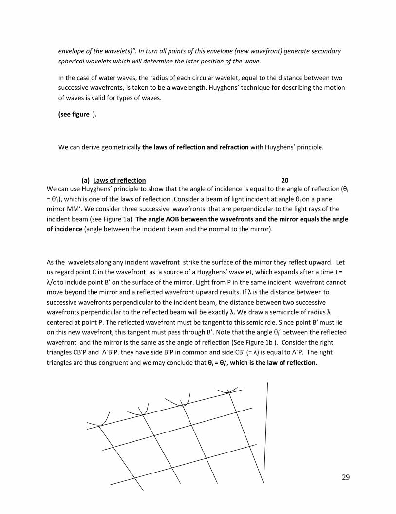
Statement of Huyghens’ principle: “All points of a wavefront can be
considered as a source of secondary spherical wavelets which spread out in all directions. After a
time t the new position of a wavefront is the surface tangent to the secondary wavelets (i.e.,
29
envelope of the wavelets)”. In turn all points of this envelope (new wavefront) generate secondary
spherical wavelets which will determine the later position of the wave.
In the case of water waves, the radius of each circular wavelet, equal to the distance between two
successive wavefronts, is taken to be a wavelength. Huyghens’ technique for describing the motion
of waves is valid for types of waves.
(see figure ).
We can derive geometrically the laws of reflection and refraction with Huyghens’ principle.
(a) Laws of reflection 20 We can use Huyghens’ principle to show that the angle of incidence is equal to the angle of reflection (θi
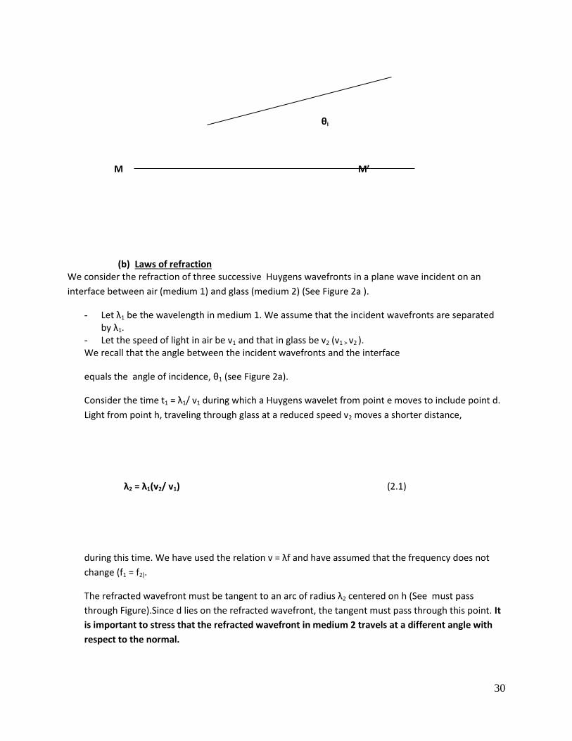
= θ’i), which is one of the laws of reflection .Consider a beam of light incident at angle θi on a plane
mirror MM’. We consider three successive wavefronts that are perpendicular to the light rays of the
incident beam (see Figure 1a). The angle AOB between the wavefronts and the mirror equals the angle
of incidence (angle between the incident beam and the normal to the mirror).
As the wavelets along any incident wavefront strike the surface of the mirror they reflect upward. Let
us regard point C in the wavefront as a source of a Huyghens’ wavelet, which expands after a time t =
λ/c to include point B’ on the surface of the mirror. Light from P in the same incident wavefront cannot
move beyond the mirror and a reflected wavefront upward results. If λ is the distance between to
successive wavefronts perpendicular to the incident beam, the distance between two successive
wavefronts perpendicular to the reflected beam will be exactly λ. We draw a semicircle of radius λ
centered at point P. The reflected wavefront must be tangent to this semicircle. Since point B’ must lie
on this new wavefront, this tangent must pass through B’. Note that the angle θi’ between the reflected
wavefront and the mirror is the same as the angle of reflection (See Figure 1b ). Consider the right
triangles CB’P and A’B’P. they have side B’P in common and side CB’ (= λ) is equal to A’P. The right
triangles are thus congruent and we may conclude that θi = θi’, which is the law of reflection.
30
θi
M M’
(b) Laws of refraction We consider the refraction of three successive Huygens wavefronts in a plane wave incident on an
interface between air (medium 1) and glass (medium 2) (See Figure 2a ).
- Let λ1 be the wavelength in medium 1. We assume that the incident wavefronts are separated by λ1.
- Let the speed of light in air be v1 and that in glass be v2 (v1 > v2 ). We recall that the angle between the incident wavefronts and the interface
equals the angle of incidence, θ1 (see Figure 2a).
Consider the time t1 = λ1/ v1 during which a Huygens wavelet from point e moves to include point d.
Light from point h, traveling through glass at a reduced speed v2 moves a shorter distance,
λ2 = λ1(v2/ v1) (2.1)
during this time. We have used the relation v = λf and have assumed that the frequency does not
change (f1 = f2).
The refracted wavefront must be tangent to an arc of radius λ2 centered on h (See must pass
through Figure).Since d lies on the refracted wavefront, the tangent must pass through this point. It
is important to stress that the refracted wavefront in medium 2 travels at a different angle with
respect to the normal.
31
We call θ2 the angle between the refracted wavefront and the interface. It is clear that θ2 represents
the angle of refraction. To derive the Snell’s law, we consider the right triangles hde and hdf. They
have one side (hd) in common. Further, we see that
sin θ1 = λ1/hd and sin θ2 = λ2/hd (2 .2)
Upon dividing and taking into account Eq. (2. 1), we have:
[sin θ1/ sin θ2+ = λ1/ λ2 = v1/v2
Using the definition of the index of refraction, (c/v1) = n1 and (c/v2) = n2, we get
[sin θ1/ sin θ2] = [nn
nn
cc
1
2
21
)/()( ]
Upon rearrangement, we can write finally
n1 sin θ1 = n2 sin θ2 (2.3).
Thus, we have derived the Snell’s law of refraction using the wave nature of light.

32