Embed Size (px)
Citation preview

ABB Drives
User�s ManualResolver InterfaceFEN-21


Resolver InterfaceFEN-21
User�s Manual
3AFE68784859 Rev C EN
EFFECTIVE: 20.04.2007
© 2007 ABB Oy. All Rights Reserved.


5
Safety instructions
OverviewThis chapter states the general safety instructions that must be followed when installing and operating the FEN-21 Resolver Interface.
In addition to the safety instructions given below, read the complete safety instructions of the specific drive you are working on.
These warnings are intended for all who work on the drive. Ignoring the instructions can cause physical injury or death, or damage the equipment.
General safety instructionsWarning! All electrical installation and maintenance work on the drive should be carried out by qualified electricians only.
The drive and adjoining equipment must be properly earthed.
Do not attempt any work on a powered drive. After switching off the mains, always allow the intermediate circuit capacitors 5 minutes to discharge before working on the frequency converter, the motor or the motor cable. It is good practice to check (with a voltage indicating instrument) that the drive is in fact discharged before beginning work.
The motor cable terminals of the drive are at a dangerously high voltage when mains power is applied, regardless of motor operation.
There can be dangerous voltages inside the drive from external control circuits even when the drive mains power is shut off. Exercise appropriate care when working on the unit.
Safety instructions

6
Safety instructions

7
Table of Contents
Safety instructions . . . . . . . . . . . . . . . . . . . . . . . . . . . . . . . . . . . . . . . . . . . . 5
Overview . . . . . . . . . . . . . . . . . . . . . . . . . . . . . . . . . . . . . . . . . . . . . . . . . . . . . 5General safety instructions . . . . . . . . . . . . . . . . . . . . . . . . . . . . . . . . . . . . . . . 5
Table of Contents . . . . . . . . . . . . . . . . . . . . . . . . . . . . . . . . . . . . . . . . . . . . . 7
Introduction . . . . . . . . . . . . . . . . . . . . . . . . . . . . . . . . . . . . . . . . . . . . . . . . . . 9
Intended audience . . . . . . . . . . . . . . . . . . . . . . . . . . . . . . . . . . . . . . . . . . . . . . 9Before you start . . . . . . . . . . . . . . . . . . . . . . . . . . . . . . . . . . . . . . . . . . . . . . . . 9What this manual contains . . . . . . . . . . . . . . . . . . . . . . . . . . . . . . . . . . . . . . . 9
Overview . . . . . . . . . . . . . . . . . . . . . . . . . . . . . . . . . . . . . . . . . . . . . . . . . . . 11
Overview . . . . . . . . . . . . . . . . . . . . . . . . . . . . . . . . . . . . . . . . . . . . . . . . . . . . 11The FEN-21 Resolver Interface . . . . . . . . . . . . . . . . . . . . . . . . . . . . . . . . . . . 11Compatibility . . . . . . . . . . . . . . . . . . . . . . . . . . . . . . . . . . . . . . . . . . . . . . . . . 12
Installation . . . . . . . . . . . . . . . . . . . . . . . . . . . . . . . . . . . . . . . . . . . . . . . . . . 13
Setting the supply voltage . . . . . . . . . . . . . . . . . . . . . . . . . . . . . . . . . . . . . . . 13Mounting . . . . . . . . . . . . . . . . . . . . . . . . . . . . . . . . . . . . . . . . . . . . . . . . . . . . 14Terminal designations . . . . . . . . . . . . . . . . . . . . . . . . . . . . . . . . . . . . . . . . . . 15Encoder wiring . . . . . . . . . . . . . . . . . . . . . . . . . . . . . . . . . . . . . . . . . . . . . . . . 19Phasing . . . . . . . . . . . . . . . . . . . . . . . . . . . . . . . . . . . . . . . . . . . . . . . . . . . . . 24Programming . . . . . . . . . . . . . . . . . . . . . . . . . . . . . . . . . . . . . . . . . . . . . . . . . 25
Fault tracing . . . . . . . . . . . . . . . . . . . . . . . . . . . . . . . . . . . . . . . . . . . . . . . . . 27
Diagnostic LEDs . . . . . . . . . . . . . . . . . . . . . . . . . . . . . . . . . . . . . . . . . . . . . . 27
Technical data . . . . . . . . . . . . . . . . . . . . . . . . . . . . . . . . . . . . . . . . . . . . . . . 29
Table of Contents

8
Table of Contents

9
Introduction
Intended audienceThe manual is intended for the people who are responsible for commissioning and using an FEN-21 Resolver Interface. The reader is expected to have a basic knowledge of electrical fundamentals, electrical wiring practices and how to operate the drive.
Before you startIt is assumed that the drive is installed and the drive power supply is switched off before starting the installation of the extension module. Ensure that all dangerous voltages connected from external control circuits to the inputs and outputs of the drive are switched off.
In addition to conventional installation tools, have the drive manuals available during the installation as they contain important information not included in this manual. The drive manuals are referred to at various points of this document.
What this manual containsThis manual contains information on the wiring, configuration and use of the FEN-21 Resolver Interface.
Safety instructions are featured in the first few pages of this manual.
Overview contains a short description of the FEN-21.
Installation contains instructions for hardware settings, mounting and cabling.
Fault tracing explains the LED indications of the FEN-21.
Technical data contains detailed technical information.
Introduction

10
Introduction
11
Overview
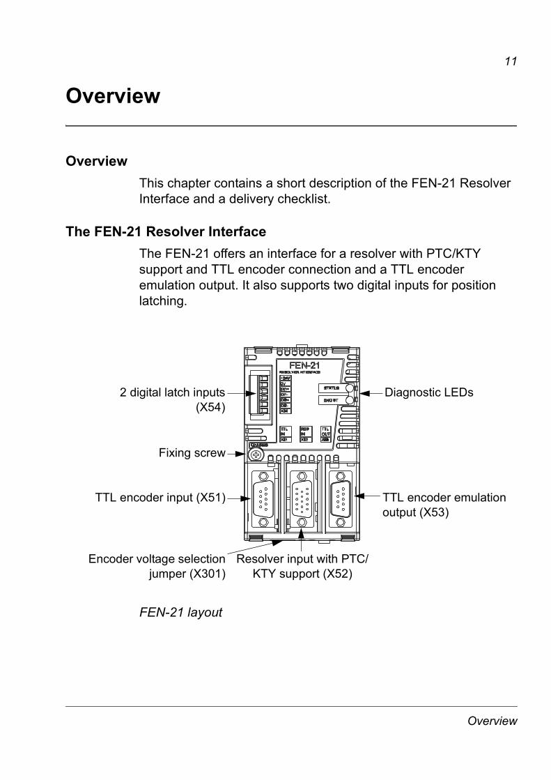
Overview This chapter contains a short description of the FEN-21 Resolver Interface and a delivery checklist.
The FEN-21 Resolver InterfaceThe FEN-21 offers an interface for a resolver with PTC/KTY support and TTL encoder connection and a TTL encoder emulation output. It also supports two digital inputs for position latching.
FEN-21 layout
TTL encoder emulation output (X53)
Resolver input with PTC/KTY support (X52)
TTL encoder input (X51)
Fixing screw
2 digital latch inputs(X54)
Diagnostic LEDs
Encoder voltage selectionjumper (X301)
Overview

12
Isolation areasThe following figure describes the different isolation areas of the module.
The shields of sockets X51 and X52 and plug X53 are connected to chassis. The fixing screw connects the chassis to ground.
Compatibility
ResolversThe FEN-21 is compatible with resolvers, which are excited by sinusoidal voltage (to the rotor winding), and which generate sine and cosine signals proportional to the rotor angle (to stator windings). Amplitude and frequency of the excitation signal can be adjusted in range 4�12 Vrms, 1�20 kHz. Transformation ratio of the resolver must be such that sine and cosine signals remains in range 2�7 Vrms.
TTL EncodersThe FEN-21 is compatible with TTL incremental encoders with 1�65535 pulses / rev and it supports reference mark.
X53
X52
X51
X54
X20
1
C
BA
CHASSIS
TTL encoder emulation output
Resolver input
TTL encoder input
Digital latchesFixing screw
Connection to the drive
Overview

13
Installation
Warning! Follow the safety instructions given in this guide and in the drive hardware manual.
Setting the supply voltage
Warning! Selecting the wrong supply voltage may damage or break the encoder.
A selectable supply voltage is provided for the TTL encoders input. A +5.5 V or a +24 V voltage for a TTL encoder can be selected by a jumper as described by the following figure.
Note: If an external power supply is used, the appropriate jumper must be removed.
TTL Encoder (X51) Not used
+24 V +5.5 V
Installation
14
Note: If another FEN interface�s TTL emulation output is connected to TTL input, the appropriate jumper must be removed.
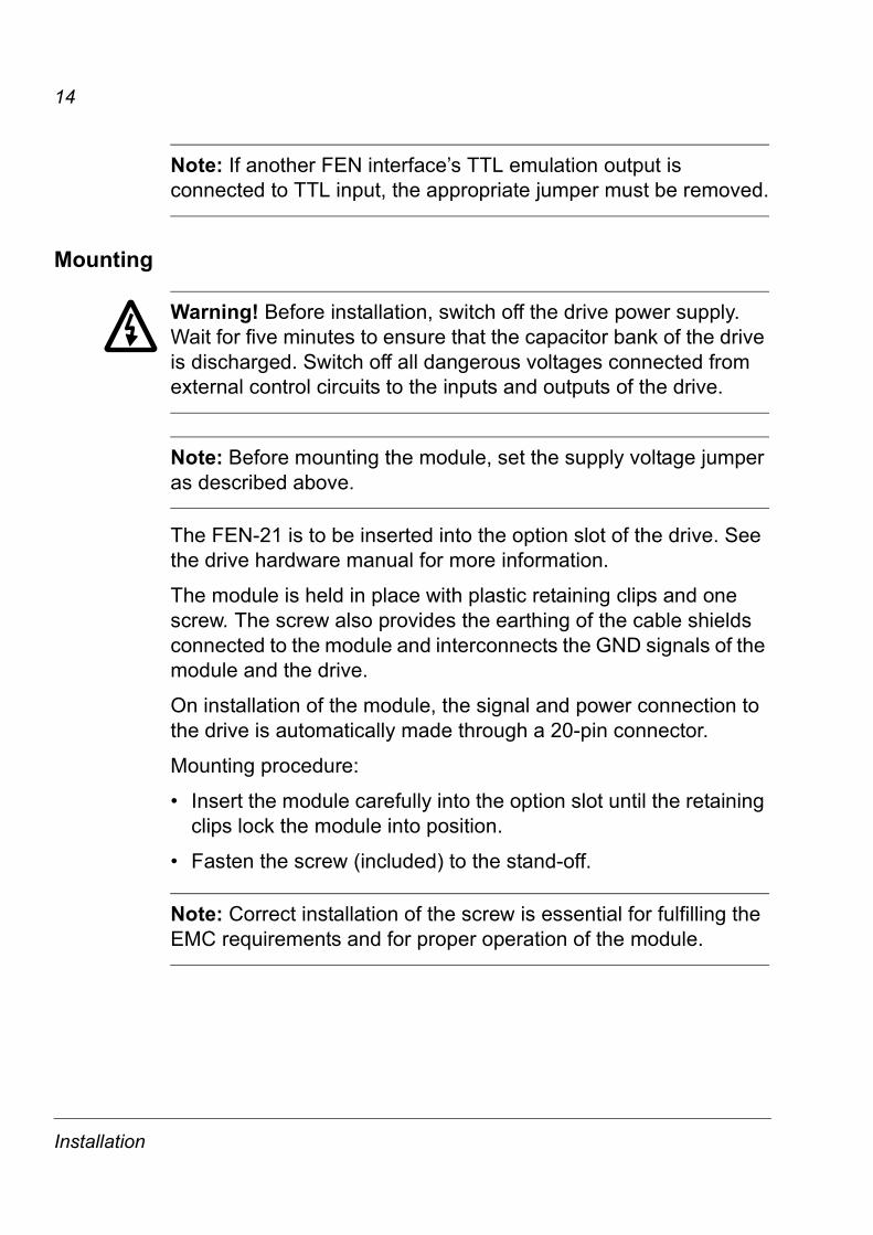
Mounting
Warning! Before installation, switch off the drive power supply. Wait for five minutes to ensure that the capacitor bank of the drive is discharged. Switch off all dangerous voltages connected from external control circuits to the inputs and outputs of the drive.
Note: Before mounting the module, set the supply voltage jumper as described above.
The FEN-21 is to be inserted into the option slot of the drive. See the drive hardware manual for more information.
The module is held in place with plastic retaining clips and one screw. The screw also provides the earthing of the cable shields connected to the module and interconnects the GND signals of the module and the drive.
On installation of the module, the signal and power connection to the drive is automatically made through a 20-pin connector.
Mounting procedure:
� Insert the module carefully into the option slot until the retaining clips lock the module into position.
� Fasten the screw (included) to the stand-off.
Note: Correct installation of the screw is essential for fulfilling the EMC requirements and for proper operation of the module.
Installation

15
Terminal designations
Abbreviations
TTL encoder input (X51)
TTL input (X51) pin order
AI Analog inAO Analog outDI Digital inDO Digital outPO Power out
Pin Name Direction Description
1 A+ DI Channel A+
2 B+ DI Channel B+
3 Z+ DI Channel Z+
4 COM_C - Common
5 VCC_ENC_1 PO Supply voltage
6 A- DI Channel A-
7 B- DI Channel B-
8 Z- DI Channel Z-
9 COM_C - Common
- Shield - Shield
VCC_ENC_1 COM_C Z+ B+ A+
A-COM_C Z- B-
12345
6789
Installation

16
Resolver input
*Optional mounting method for twisted pairs� shields
Pin Name Direction Description
1 SIN- AI Inverted sine signal
2 COS- AI Inverted cosine signal
3 PTC/KTY AI Temperature sensor
4 COM_B - Common, reserved for temperature sensor
5 EXCITATION+ AO Excitation signal+
6 SIN+ AI Sine signal
7 COS+ AI Cosine signal
8 GND - Chassis, reserved for a twisted pair�s shield*
9 COM_B - Common
10 EXCITATION- AO Excitation signal-
11 GND - Chassis, reserved for a twisted pair�s shield*
12 COM_B - Common
13 COM_B - Common
14 GND - Chassis, reserved for a twisted pair�s shield*
15 GND - Chassis, reserved for a twisted pair�s shield*
- Shield - Shield
Installation

17
Resolver input (X52) pin order
TTL encoder emulation output (X53)
Pin Name Direction Description
1 A+ DO Channel A+
2 B+ DO Channel B+
3 Z+ DO Channel Z+
4 COM_B - Common
5 NC - Not connected
6 A- DO Channel A-
7 B- DO Channel B-
8 Z- DO Channel Z-
9 COM_B - Common
- Shield - Shield
12345
678910
1112131415
EXCITATION+PTC/
KTY_0V PTC/KTY COS- SIN-
EXCITATION- COM_B GND SIN+
GNDGND GNDCOM_B
COS+
COM_B
Installation

18
TTL encoder output (X53) pin order
Digital inputs for position latching (X54)
Pin Name Direction Description
1 +24V_C PO Supply voltage
2 COM_C - Common
3 DI_1+ DI Latch signal 1
4 DI_1- - Latch signal 1 return
5 DI_2+ DI Latch signal 2
6 DI_2- - Latch signal 2 return
EM_A+ EM_B+ EM_Z+ COM_B COM_B
COM_BEM_A- EM_B- EM_Z-
1 2 3 4 5
6 7 8 9
NC
Installation

19
Encoder wiringThe resolver and encoder should be connected to the FEN-21 with a shielded instrumentation cable, preferably with twisted pairs. See also the encoder and resolver manual for additional requirements. To prevent the inputs from being disturbed, the cable shield must be connected to the chassis. The connection is made automatically through the metal hood of the plug, if the cables are connected through the cable clamp of the plug.
Cable shield connected to the cable clamp
Note: Do not route the encoder cables parallel to power (e.g. motor) cables.
Tightening torque is 0.3 Nm (2.7 lbf·in.) for the plugs.
The allocation of twisted pairs is described for each connector in the following tables.
Cable clampMetal hood
Cable bushing
Installation

20
TTL Encoder input (X51)The cable should have minimum 4 cable pairs. A fifth cable pair shared between Vcc an 0V pins allows for a longer cable.
* Two wires soldered to the same pin.
TTL Encoder input (X51)
Cable pair number
Signals name X51 connecting plug pin number (9-pins)
Notes
1A+ 1
A- 6
2B+ 2
B- 7
3Z+ 3
Z- 8
4VCC_ENC_1 5
COM_C 9
5VCC_ENC_1* 5* OPTIONAL
COM_C 4 OPTIONAL
Optional
FEN-21X51
A+A-
B-B+
Z+Z-VCC_ENC_1COM_C
0VVCC
VCC0V
00
22
11
5 1
9 6VCC_ENC_1COM_C 4
59
83
72
61
Installation

21
Resolver input (X52)The cable should have 4 twisted pairs. Additional 0V and GND pins are reserved for connecting cable shields. The shields should be connected either to 0V or to GND (chassis). Connection of the shields to GND (chassis) can also be made through theD-connector hood cable clamping.
Cable pair number
Signals name X52 connecting plug pin number (9-pins)
Notes
1SIN+ 6
SIN- 1
2COS+ 7
COS- 2
3EXCITATION+ 5
EXCITATION- 10
4PTC/KTY-84 3 Temperature
sensor
PTC/KTY_0V 4 Temperature sensor, return
Twisted pair shields
connected to 0V
COM_B 9 Shield / optional
COM_B 12 Shield / optional
COM_B 13 Shield / optional
Twisted pair shields
connected to GND
(chassis)
GND 8 Shield / optional
GND 11 Shield / optional
GND 14 Shield / optional
GND 15 Shield / optional
Installation

22
Resolver input (X52)
TTL Encoder emulation output (X53)The cable should have 4 cable pairs.
Cable pair number
Signals name
X53 connecting plug pin number (9-pins)
Notes
1EM_A+ 1
EM_A- 6
2EM_B+ 2
EM_B- 7
3EM_Z+ 3
EM_Z- 8
4COM_B 4
COM_B 9
FEN-21X52
SIN+SIN-
COS-COS+
EXCITATION+EXCITATION-PTC/KTY-84PTC/KTY_0V
0V0V
SENSOR0V
EXCITATIONEXCITATION
22
11
5 1
15 11
12
34
105
27
16
9
138
111415
0VGNDGNDGNDGND
10 6
Installation

23
TTL encoder emulation output (X53)
Digital inputs for position latching (X54)
Digital inputs for position latching (X54)
Cable pair number
Signals name
X54 connecting header pin number (6-pins)
Notes
1+24V_C 1
COM_C 2
2DI_1+ 3
DI_1- 4
3DI_2+ 5
DI_2- 6
FEN-21X53
EM_A+EM_A-
EM_B-EM_B+
EM_Z+EM_Z-COM_BCOM_B
0V0V
00
22
11
1 5
6 9
NC -5
49
83
72
61
FEN-21X54
DI1+DI1-
DI2-DI2+
VCCCOM_C0V
VCC
22
11
21
65
43
Installation

24
PhasingWhen the encoder is connected correctly, running the drive in the Forward (positive speed reference) direction should produce a positive encoder speed feedback.
On incremental encoders, the two output channels, usually marked 1 and 2 or A and B, are 90° (electrical) apart from each other. When rotated clockwise, most encoders � but not all � have channel 1 leading channel 2 as illustrated below. Determine the leading channel by referring to the encoder documentation or by measuring with an oscilloscope.
The encoder output channel that leads when the drive runs Forward should be connected to FEN-21 input A, the output channel that trails to FEN-21 input B.
The zero reference output channel (usually marked 0, N or Z) needs to be connected in positioning applications only.
A+ or A or 1
A- or A or 1
B+ or B or 2
B- or B or 2
Z+ or Z or 0
Z- or Z or 0
Installation

25
Excitation signalThe FEN-21 feeds the resolver differentially with an excitation signal. The amplitude and the frequency are adjustable by software in the following boundaries
The following figure shows the SIN and COS outputs and the excitation signal.
ProgrammingThe FEN-21 is programmed through drive parameters. These parameters must be checked and adjusted according to the encoder and resolver data sheet. For further information, see the drive Firmware Manual.
Excitation Signal
Amplitude Frequency Current, max.
4�12 Vrms 1�20 kHz 100 mArms
Excitation
SIN
COS
Carrier in phase with excitation
Carrier in anti-phase with excitation
Carrier in anti-phase with excitation
Carrier in phase with excitation
Carrier in phase with excitation
180° 270°90°Zero position Zero position
Installation

26
Installation

27
Fault tracing
Diagnostic LEDsThe FEN-21 is equipped with two diagnostic LEDs. The STATUS LED describes the status of the FEN-21 and the ENC ST LED the status of the encoders. Description of the LED signals is presented below.
Colour Description
STAT
US
LED Green OK
Orange Not initialized or communication fault to control unit
Red Not in use
ENC
ST
LED
Green Encoder(s) OK
Red TTL encoder (X51) fault
Orange Resolver (X52) fault
Red / orange swapping
TTL encoder fault X51 & resolver X52 fault
Red flashing TTL encoder (X51) warning
Orange flashing
Resolver (X52) warning
Fault tracing

28
Fault tracing

29
Technical data
Dimensions:
General� Max. power consumption: 350 mA at 24 V (Max. combined
power consumption of encoders, latches and cabling 5W)
� Degree of protection: IP20
� Ambient conditions: The applicable ambient conditions specified for the drive in its Hardware Manual are in effect.
Connectors� 20-pin socket
� 9-pin D-sub plug
� 15-pin D-sub plug
� 9-pin D-sub socket
63 mm
106
mm
26 mm
31 mm1.22 in
1.02 in
4.17
in
2.48 in
Technical data
30
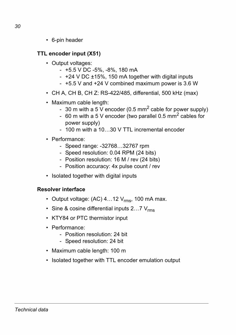
� 6-pin header
TTL encoder input (X51)� Output voltages:
- +5.5 V DC -5%, -8%, 180 mA- +24 V DC ±15%, 150 mA together with digital inputs- +5.5 V and +24 V combined maximum power is 3.6 W
� CH A, CH B, CH Z: RS-422/485, differential, 500 kHz (max)
� Maximum cable length:- 30 m with a 5 V encoder (0.5 mm2 cable for power supply)- 60 m with a 5 V encoder (two parallel 0.5 mm2 cables for
power supply)- 100 m with a 10�30 V TTL incremental encoder
� Performance:- Speed range: -32768�32767 rpm- Speed resolution: 0.04 RPM (24 bits)- Position resolution: 16 M / rev (24 bits)- Position accuracy: 4x pulse count / rev
� Isolated together with digital inputs
Resolver interface� Output voltage: (AC) 4�12 Vrms, 100 mA max.
� Sine & cosine differential inputs 2�7 Vrms
� KTY84 or PTC thermistor input
� Performance:- Position resolution: 24 bit- Speed resolution: 24 bit
� Maximum cable length: 100 m
� Isolated together with TTL encoder emulation output
Technical data
31
TTL encoder emulation output (X53)� Supports emulation of TTL incremental encoder,
1�65535 pulses / rev, reference mark
� CH A, CH B, CH Z: RS-422/485, 500 kHz (max)
� Maximum cable length: 100 m
� Performance- Speed range: -32768�32767 rpm- Position resolution: 4x pulse count / rev
� Isolated together with absolute encoder input
Digital inputs for position latch (X54)� Output voltage: +24 V DC ±15%, short-circuit proof
� Signal levels: < 5 V = 0, > 15 V = 1
� Isolated together with TTL encoder input
Technical data

32
Technical data


3AFE
6878
4859
Rev
C E
NE
FFE
CTI
VE
: 20.
04.2
007
ABB OyAC DrivesP.O. Box 184FIN-00381 HELSINKIFINLANDTelephone +358 10 22 11Telefax +358 10 22 22681Internet http://www.abb.com
ABB Inc.Automation TechnologiesDrives & Motors16250 West Glendale DriveNew Berlin, WI 53151USATelephone 262 785-3200
800-HELP-365Telefax 262 780-5135
ABB Beijing Drive Systems Co. Ltd.No. 1, Block D, A-10 Jiuxianqiao BeiluChaoyang DistrictBeijing, P.R. China, 100015Telephone +86 10 5821 7788Fax +86 10 5821 7618