Embed Size (px)
Citation preview
Femtocell and UMA TID
NENA Technical Information Document 03-509 – Femtocell and UMA
Version 1, January 27, 2011
Prepared by: National Emergency Number Association (NENA) Network Technical Committee
Working Group
Published by NENA
Printed in USA
NENA
TECHNICAL INFORMATION DOCUMENT
NENA Femtocell and UMA
Technical Information Document
NENA 03-509, Version 1, January 27, 2011
Issue 1, January 27, 2011 Page 2 of 19
NOTICE
The National Emergency Number Association (NENA) publishes this document as an information
source for the designers and manufacturers of systems to be utilized for the purpose of processing
emergency calls. It is not intended to provide complete design specifications or parameters or to
assure the quality of performance for systems that process emergency calls.
NENA reserves the right to revise this TID for any reason including, but not limited to:
conformity with criteria or standards promulgated by various agencies
utilization of advances in the state of the technical arts
or to reflect changes in the design of network interface or services described herein.
It is possible that certain advances in technology will precede these revisions. Therefore, this TID
should not be the only source of information used. NENA recommends that members contact their
Telecommunications Carrier representative to ensure compatibility with the 9-1-1 network.
Patents may cover the specifications, techniques, or network interface/system characteristics
disclosed herein. No license expressed or implied is hereby granted. This document shall not be
construed as a suggestion to any manufacturer to modify or change any of its products, nor does this
document represent any commitment by NENA or any affiliate thereof to purchase any product
whether or not it provides the described characteristics.
This document has been prepared solely for the voluntary use of E9-1-1 Service System Providers,
network interface and system vendors, participating telephone companies, etc.
By using this document, the user agrees that NENA will have no liability for any consequential,
incidental, special, or punitive damages arising from use of the document.
NENA’s Technical Committee has developed this document. Recommendations for change to this
document may be submitted to:
National Emergency Number Association
1700 Diagonal Rd, Suite 500
Alexandria, VA 22314
202.466.4911
NENA Femtocell and UMA
Technical Information Document
NENA 03-509, Version 1, January 27, 2011
Issue 1, January 27, 2011 Page 3 of 19
Acknowledgments:
This document has been developed by the National Emergency Number Association (NENA)
Technical Committee and its Femtocell/UMA Sub-committee.
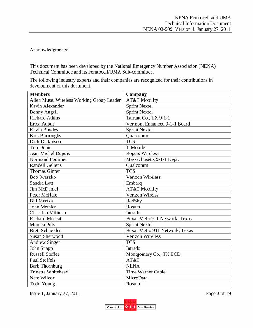
The following industry experts and their companies are recognized for their contributions in
development of this document.
Members Company
Allen Muse, Wireless Working Group Leader AT&T Mobility
Kevin Alexander Sprint Nextel
Bonny Angell Sprint Nextel
Richard Atkins Tarrant Co., TX 9-1-1
Erica Aubut Vermont Enhanced 9-1-1 Board
Kevin Bowles Sprint Nextel
Kirk Burroughs Qualcomm
Dick Dickinson TCS
Tim Dunn T-Mobile
Jean-Michel Dupuis Rogers Wireless
Normand Fournier Massachusetts 9-1-1 Dept.
Randell Gellens Qualcomm
Thomas Ginter TCS
Bob Iwaszko Verizon Wireless
Sandra Lott Embarq
Jim McDaniel AT&T Mobility
Peter McHale Verizon Wirelss
Bill Mertka RedSky
John Metzler Rosum
Christian Militeau Intrado
Richard Muscat Bexar Metro911 Network, Texas
Monica Puls Sprint Nextel
Brett Schneider Bexar Metro 911 Network, Texas
Susan Sherwood Verizon Wireless
Andrew Singer TCS
John Snapp Intrado
Russell Steffee Montgomery Co., TX ECD
Paul Stoffels AT&T
Barb Thornburg NENA
Trinette Whitehead Time Warner Cable
Nate Wilcox MicroData
Todd Young Rosum
NENA Femtocell and UMA
Technical Information Document
NENA 03-509, Version 1, January 27, 2011
Issue 1, January 27, 2011 Page 4 of 19
Victoria Zeller Sprint Nextel
Steve Zweifach Sprint Nextel
Arayna Firdaus TCS
Judy Ocondi TCS
Tracy Holick Level 3
NENA Femtocell and UMA
Technical Information Document
NENA 03-509, Version 1, January 27, 2011
Issue 1, January 27, 2011 Page 5 of 19
TABLE OF CONTENTS
1. EXECUTIVE OVERVIEW .............................................................................................................................. 7
1.1. PURPOSE AND SCOPE OF DOCUMENT ............................................................................................................... 7
1.2. FEMTOCELL AND UMA .................................................................................................................................... 7
2. INTRODUCTION .............................................................................................................................................. 8
2.1. OPERATIONAL IMPACTS SUMMARY ................................................................................................................. 8
2.2. SECURITY IMPACTS SUMMARY ........................................................................................................................ 8
2.3. DOCUMENT TERMINOLOGY.............................................................................................................................. 8
2.4. REASON FOR ISSUE/REISSUE ............................................................................................................................ 8
2.5. RECOMMENDATION FOR ADDITIONAL DEVELOPMENT WORK ......................................................................... 9
2.6. DATE COMPLIANCE .......................................................................................................................................... 9
2.7. ANTICIPATED TIMELINE ................................................................................................................................... 9
2.8. COSTS FACTORS ............................................................................................................................................... 9
2.9. FUTURE PATH PLAN CRITERIA FOR TECHNICAL EVOLUTION ........................................................................... 9
2.10. COST RECOVERY CONSIDERATIONS ............................................................................................................... 10
2.11. INTELLECTUAL PROPERTY RIGHTS POLICY .................................................................................................... 10
2.12. ACRONYMS/ABBREVIATIONS/DEFINITIONS ................................................................................................... 11
3. TECHNICAL DESCRIPTION ....................................................................................................................... 13
3.1. UMA / FEMTOCELL SIMILARITIES AND DIFFERENCES ................................................................................... 13
3.2. INFORMATION SENT IN ALI RECORD FROM CARRIERS USING UMA / FEMTOCELL. ........................................ 13
3.2.1 Class of Service ........................................................................................................................................ 13
3.2.2 Company ID.............................................................................................................................................. 14
3.2.3 Address Field Information ........................................................................................................................ 14
3.2.4 Latitude and Longitude ............................................................................................................................. 14
3.2.5 Customer Name ........................................................................................................................................ 14
3.2.6 pANIs (ESRK / ESQK) .............................................................................................................................. 15
3.3. CLASS OF SERVICE AND LOCATION WITHIN MACRO NETWORK ..................................................................... 15
3.4. CLASS OF SERVICE AND LOCATION – OUTSIDE MACRO NETWORK ................................................................ 15
3.5. FEMTOCELL VERSUS HANDSET LOCATION ..................................................................................................... 15
3.6. ADDRESS QUESTIONS ..................................................................................................................................... 16
3.7. REBIDDING / ADDRESS AND LOCATION .......................................................................................................... 16
3.8. ROUTING OF CALLS ........................................................................................................................................ 16
3.9. SERVICE RESTRICTIONS AND NON SERVICE INITIATED CALLS ....................................................................... 16
NENA Femtocell and UMA
Technical Information Document
NENA 03-509, Version 1, January 27, 2011
Issue 1, January 27, 2011 Page 6 of 19
3.10. HANDOFFS – FEMTOCELL TO MACROCELL..................................................................................................... 17
3.11. HANDOFFS – MACROCELL TO FEMTOCELL..................................................................................................... 17
3.12. PORTABILITY OF FEMTOCELL ......................................................................................................................... 17
3.13. CALLBACK TO PHONE ON A FEMTOCELL ........................................................................................................ 17
3.14. PHASE 1 PSAPS ............................................................................................................................................. 17
3.15. ABILITY AT FEMTOCELLS TO CONNECT TO WIRED DEVICE (I.E. RJ-11 JACK) .................................................. 17
3.16. TRUNKS TO PSAP SELECTIVE ROUTERS SUPPORTING CALLS FROM FEMTOCELLS......................................... 18
3.17. RJ-11 JACK AND UNIQUE PHONE NUMBERS CLASS OF SERVICE. .................................................................... 18
3.18. CONFIDENCE AND UNCERTAINTY. ................................................................................................................. 18
3.19. ELT OR ENGLISH LANGUAGE TRANSLATION FIELDS ..................................................................................... 18
3.20. NETWORK CONSIDERATIONS .......................................................................................................................... 18
4. NENA NG9-1-1 ................................................................................................................................................. 18
5. EXHIBITS ........................................................................................................................................................ 19
6. REFERENCES ................................................................................................................................................. 19
NENA Femtocell and UMA
Technical Information Document
NENA 03-509, Version 1, January 27, 2011
Issue 1, January 27, 2011 Page 7 of 19
1. Executive Overview
1.1. Purpose and Scope of Document
The purpose of this “Femtocel/UMA Technical Information Document” is to describe in technical as
well as operational terms the current state of femtocell and UMA deployments with respect to call
processing of E9-1-1 calls, and to identify the impacts to Public Safety Answering Points (PSAPs) of
receiving and processing calls from femtocells. This TID also describes the current 9-1-1
infrastructure, next generation emergency networks, and discusses integration of femtocells and
UMA technologies into those networks. This TID will provide information to allow the National
Emergency Number Association (NENA) and other interested parties to develop new
communications methodologies, standards, and protocols to facilitate emergency communications
between users of femtocells/UMA and PSAPs.
This document also addresses situations in which a femtocell/UMA device offers POTS type service
as an additional a feature, since this information is also relevant to public safety agency handling of
calls from these devices.
Implementation-specific details pertaining to current deployments have been included in this TID to
convey the current state of affairs. Inclusion of this detail does not imply that the deployment is
correct and acceptable to PSAPs. The working group expects that information contained within this
document may be used to generate future recommendations or standards.
1.2. Femtocell and UMA
By definition, a femtocell is a cell that operates in the geographic area of a carrier’s licensed
footprint. Femtocells communicate with mobile devices using the carrier’s licensed spectrum of the
carrier’s network and interconnect to the carrier’s’ network using a broadband connection.
Depending upon the carriers’ product specification, a femtocell may accept new call originations,
process hand-offs between the femtocell and to the macro network, and process hand-offs between
the macro network and the femtocell. A femtocell typically extends cellular communications service
by providing base station capability in a small unit located at the customer’s home or small business
premises, providing enhanced mobile coverage. In addition, depending upon the carriers’
architecture and product specification, the femtocell may provide an interface for landline wired
phones, facilitate E9-1-1call completion, and may provide service for NSI (non service initialized
phones, and allow both registered users of the associated service and / or registered users of the
femtocell access to the wireless network). Depending upon the carrier’s architecture, calls may be
delivered to the E911 service provider’s selective router over the same trunks as the macro network,
or possibly over different trunks.
A UMA (Universal Mobile Access) base station is stand-alone unit that acts as a WiFi “hot-spot”
and is typically deployed in a building such as a home or small business.
Both types of devices connect to the carrier’s mobile network through a customer-supplied
broadband connection.
NENA Femtocell and UMA
Technical Information Document
NENA 03-509, Version 1, January 27, 2011
Issue 1, January 27, 2011 Page 8 of 19
Since a femtocell uses a carrier’s licensed frequencies, it allows the customer to use existing
handsets to take advantage of the service. Thus, femtocells are usually backwards-compatible with
deployed handsets, although they may also offer enhanced functionality to newer handsets.
To use the a UMA base station, a customer needs a handset that can operate both on a cellular
network and over WiFI, providing voice calls in the VoIP mode as well as over traditional cellular.
However, UMA handsets may often also be able to operate outside the customer’s premise, by
accessing WiFI “hotspots” in other locations.
Today, processing of E9-1-1 calls from femtocells and UMA devices presents challenges to both
PSAPs and to carriers. PSAPs and carriers want to provide the PSAP with enough detail so they can
process the call and dispatch in a timely and accurate manner. Due to the lack of defined standards
for femtocell deployment relative to E9-1-1, each carrier may populate ALI data fields differently
when an emergency call originates on a femtocell. This TID was prepared to reduce any cause
confusion at the PSAP which could impact emergency response time.
2. Introduction
2.1. Operational Impacts Summary
How a carrier implements their architecture to support femtocells will determine how the PSAP
recognizes and processes E9-1-1 calls.
This document compares differences among the various solutions that have been deployed or which
carriers expect to be deployed.
2.2. Security Impacts Summary
No security risks have been identified.
2.3. Document Terminology
The terms "shall", "must" and "required" are used throughout this document to indicate required
parameters and to differentiate from those parameters that are recommendations. Recommendations
are identified by the words "desirable" or "preferably".
2.4. Reason for Issue/Reissue
This is the initial issue of this document. It is intended to provide public safety with information on
how femtocells and UMA Access Points will service emergency calls to 9-1-1, and what ALI
information will be available for these calls.
NENA Femtocell and UMA
Technical Information Document
NENA 03-509, Version 1, January 27, 2011
Issue 1, January 27, 2011 Page 9 of 19
NENA reserves the right to modify this document. Upon revision, the reason(s) will be provided in
the table below.
Version Date Reason For Changes
Original Xx/xx/xxxx Initial Document Submitted to NTC for review and
approval.
2.5. Recommendation for Additional Development Work
None identified.
2.6. Date Compliance
All systems that are associated with the 9-1-1 process shall be designed and engineered to ensure
that no detrimental, or other noticeable impact of any kind, will occur as a result of a date/time
change up to 30 years subsequent to the manufacture of the system. This shall include embedded
application, computer based or any other type application.
To ensure true compliance, the manufacturer shall upon request, provide verifiable test results to an
industry acceptable test plan such as Telcordia GR-2945 or equivalent.
2.7. Anticipated Timeline
Application of the recommendation in this TID would follow current business practices.
2.8. Costs Factors
The working group did not consider any costs associated with this analysis.
2.9. Future Path Plan Criteria for Technical Evolution
In present and future applications of all technologies used for 9-1-1 call and data delivery, it is a
requirement to maintain the same level or improve on the reliability and service characteristics
inherent in present 9-1-1 system design.
New methods or solutions for current and future service needs and options should meet the criteria
below. This inherently requires knowledge of current 9-1-1 system design factors and concepts, in
order to evaluate new proposed methods or solutions against the Path Plan criteria.
Criteria to meet the Definition/Requirement:
1. Reliability/dependability as governed by NENA’s technical standards and other generally
accepted base characteristics of E9-1-1 service
2. Service parity for all potential 9-1-1 callers
NENA Femtocell and UMA
Technical Information Document
NENA 03-509, Version 1, January 27, 2011
Issue 1, January 27, 2011 Page 10 of 19
3. Least complicated system design that results in fewest components to achieve needs
(simplicity, maintainable)
4. Maximum probabilities for call and data delivery with least cost approach
5. Documented procedures, practices, and processes to ensure adequate implementation and
ongoing maintenance for 9-1-1 systems
This basic technical policy is a guideline to focus technical development work on maintaining
fundamental characteristics of E9-1-1 service by anyone providing equipment, software, or services.
2.10. Cost Recovery Considerations
Normal business practices shall be assumed to be the cost recovery mechanism.
Additional Impacts (non cost related)
The information or requirements contained in this NENA document are not expected to have
significant technical or operational impacts, based on the analysis of the authoring group.
2.11. Intellectual Property Rights Policy
NENA takes no position regarding the validity or scope of any Intellectual Property Rights or other
rights that might be claimed to pertain to the implementation or use of the technology described in
this document or the extent to which any license under such rights might or might not be available;
nor does it represent that it has made any independent effort to identify any such rights.
NENA invites any interested party to bring to its attention any copyrights, patents or patent
applications, or other proprietary rights that may cover technology that may be required to
implement this standard.
Please address the information to:
National Emergency Number Association
1700 Diagonal Rd, Suite 500
Alexandria, VA 22314
202.466.4911
NENA Femtocell and UMA
Technical Information Document
NENA 03-509, Version 1, January 27, 2011
Issue 1, January 27, 2011 Page 11 of 19
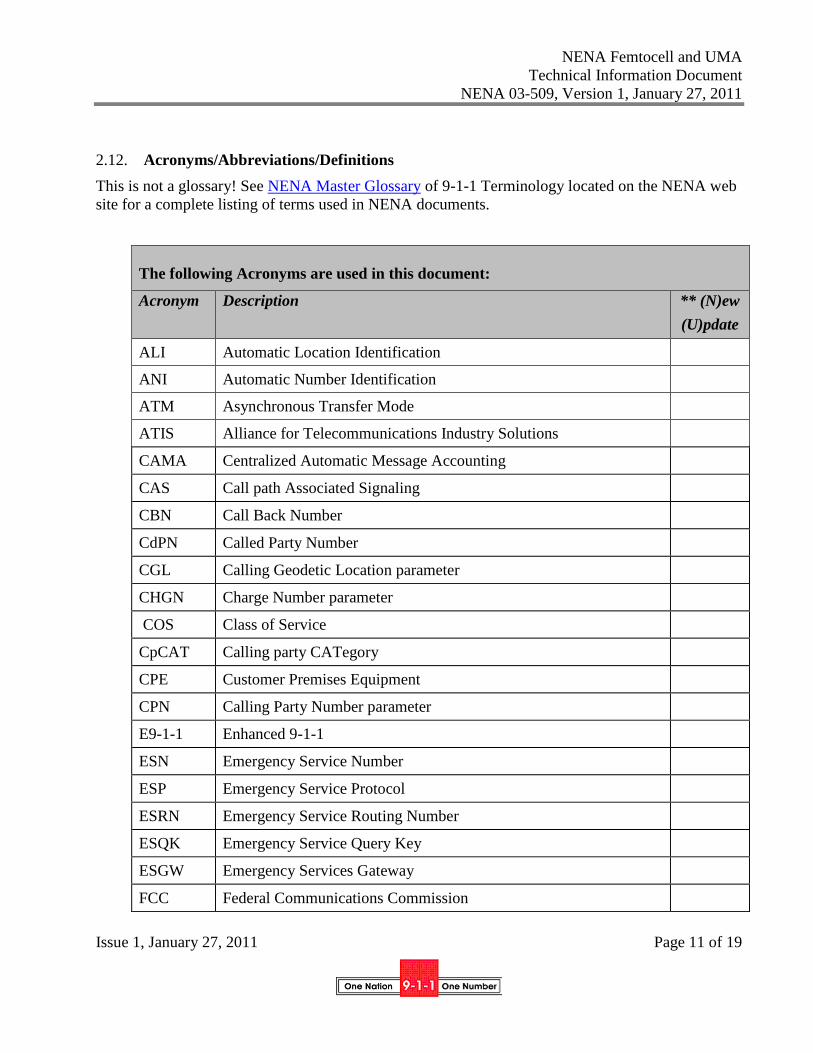
2.12. Acronyms/Abbreviations/Definitions
This is not a glossary! See NENA Master Glossary of 9-1-1 Terminology located on the NENA web
site for a complete listing of terms used in NENA documents.
The following Acronyms are used in this document:
Acronym Description ** (N)ew
(U)pdate
ALI Automatic Location Identification
ANI Automatic Number Identification
ATM Asynchronous Transfer Mode
ATIS Alliance for Telecommunications Industry Solutions
CAMA Centralized Automatic Message Accounting
CAS Call path Associated Signaling
CBN Call Back Number
CdPN Called Party Number
CGL Calling Geodetic Location parameter
CHGN Charge Number parameter
COS Class of Service
CpCAT Calling party CATegory
CPE Customer Premises Equipment
CPN Calling Party Number parameter
E9-1-1 Enhanced 9-1-1
ESN Emergency Service Number
ESP Emergency Service Protocol
ESRN Emergency Service Routing Number
ESQK Emergency Service Query Key
ESGW Emergency Services Gateway
FCC Federal Communications Commission
NENA Femtocell and UMA
Technical Information Document
NENA 03-509, Version 1, January 27, 2011
Issue 1, January 27, 2011 Page 12 of 19
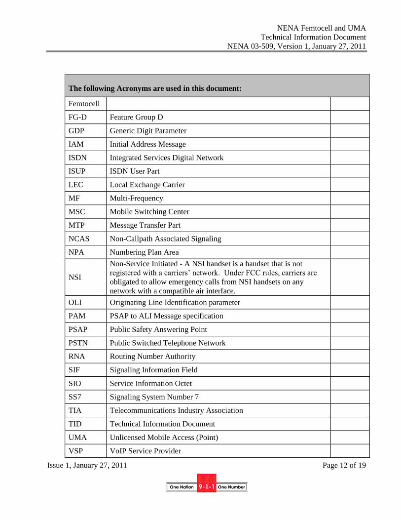
The following Acronyms are used in this document:
Femtocell
FG-D Feature Group D
GDP Generic Digit Parameter
IAM Initial Address Message
ISDN Integrated Services Digital Network
ISUP ISDN User Part
LEC Local Exchange Carrier
MF Multi-Frequency
MSC Mobile Switching Center
MTP Message Transfer Part
NCAS Non-Callpath Associated Signaling
NPA Numbering Plan Area
NSI
Non-Service Initiated - A NSI handset is a handset that is not
registered with a carriers’ network. Under FCC rules, carriers are
obligated to allow emergency calls from NSI handsets on any
network with a compatible air interface.
OLI Originating Line Identification parameter
PAM PSAP to ALI Message specification
PSAP Public Safety Answering Point
PSTN Public Switched Telephone Network
RNA Routing Number Authority
SIF Signaling Information Field
SIO Service Information Octet
SS7 Signaling System Number 7
TIA Telecommunications Industry Association
TID Technical Information Document
UMA Unlicensed Mobile Access (Point)
VSP VoIP Service Provider
NENA Femtocell and UMA
Technical Information Document
NENA 03-509, Version 1, January 27, 2011
Issue 1, January 27, 2011 Page 13 of 19
** Required entry of New or Update. Any change made to an existing Acronym,
Abbreviation or Definition constitutes an Update.
3. Technical Description
3.1. UMA / Femtocell Similarities and Differences
This TID includes information obtained from the four largest nationwide (Tier I) wireless carriers. It
was based on a series of questions submitted by public safety regarding the nature of the information
which would be displayed on a PSAP ALI screen during calls originated over a Femtocell of a UMA
Access Point. Some of these questions appear as the headers for individual sections of this
document. Primary emphasis was on noting similarities and differences between these calls and
those originating on the macro wireless network.
One carrier surveyed is providing service over UMA Access Points, and three others are deploying
Femtocells. While all four carriers participated in the preparation of this document, the description of
UMA service includes additional information from public documents.
Please note that in addition to the discussion by topic in the body of the TID, Appendix A contains a
matrix which provides a “ quick reference ” of the responses.
BACKGROUND
UMA uses 802.11 (unlicensed) frequencies to communicate to the UMA base station. In UMA
access, the handset may use any 802.11 access point that is in proximity and is accessible. This may
be a router in the home which is connected to a broadband connection or a WiFi “hot spot.” In the
UMA system, handsets are configured to place emergency calls over the macrocell, and to use the
UMA AP (VoIP) as a last resort if the macrocell network is not available. Customers of this system
must obtain from the carrier a dual mode handset that can operate on cellular and unlicensed
frequencies.
Femtocells share frequencies that are licensed to the carrier by the FCC. The Femtocell connects to
the carrier network, typically using a customer provided broadband connection, and must be used
within the carriers’ licensed geographic area. In these cases, there may or may not be a macro-cell in
close proximity to the femtocell. Customers of these systems use the same handset on the Femtocell
that they use on the carriers’ macro networks.
3.2. Information sent in ALI record from Carriers using UMA / Femtocell.
3.2.1 Class of Service
Today there are no unique classes of service assigned for calls originating on Femtocells or UMA
APs.
NENA Femtocell and UMA
Technical Information Document
NENA 03-509, Version 1, January 27, 2011
Issue 1, January 27, 2011 Page 14 of 19
3.2.2 Company ID
At least one carrier is displaying a different NENA Company ID for femtocell originated calls. Other
carriers deploying Femtocells and UMA Access Points are using the same Company ID that is used
for wireless calls on their macro networks.
3.2.3 Address Field Information
The carrier deploying UMA Access Points attempts to direct the handset in all cases to the macro
network for an emergency call. Address information would be the same as for a Phase I or Phase II
call on the macro network. This carrier says that over 99.5% of all 9-1-1 calls end up being
processed on the macro network.
Carriers deploying Femtocells are using two different addressing plans: Two carriers are providing
the cell and sector information for the nearest macro cell site. One of those carriers creates a virtual
cell in areas where there is no overlying cellular coverage. In either case, the ALI display for the site
will be the same as that provided for a macro cellular call.
The third carrier using Femtocells requires the customer to enter the address of the femtocell, and
this address is MSAG validated. It is the MSAG validated address of the femtocell that appears in
the ALI record. If a customer entered address cannot be immediately validated, the customer
entered address temporarily populates the ALI record, until the MSAG validation is completed.
3.2.4 Latitude and Longitude
In a PhaseII environment, all carriers surveyed send the geographic coordinates of the femtocell
receiver as the location estimate when the call is originated via the femtocell. The geographic
coordinates of the Femtocells are measured by an internal GPS unit at the time of setup. Therefore, it
may not be necessary for a PSAP operator to rebid to receive coordinate data, as it will probably be
available at the time of call setup and routing.
As noted in 3.2.3, the carrier providing UMA Access Points directs an emergency call whenever
possible to the macro network, and the PSAP experience will be the same as for any wireless Phase
2 call, including the need to rebid.
All carriers confirmed that in the above scenarios, the class of service of WPH2 is provided when the
latitude and longitude are sent.
3.2.5 Customer Name
All carriers surveyed indicate they will provide a different carrier name in the customer name field,
to indicate that the call was placed from a femtocell or UMA Access Point. This name incorporates
the carrier name and some indicator that a Femtocell or UMA Access Point handled the call. Some
carriers are accomplishing this with pANI ranges unique to Femtocell or UMA Access Points. As
noted above in 3.2.2, one carrier also provides a different Company ID for this purpose.
NENA Femtocell and UMA
Technical Information Document
NENA 03-509, Version 1, January 27, 2011
Issue 1, January 27, 2011 Page 15 of 19
3.2.6 pANIs (ESRK / ESQK)
Most, but not all, carriers surveyed are utilizing unique pANI ranges to indicate that the call
originated on the femtocell. Unique pANIs can enable an ALI record to contain unique company
names and/or unique Company IDs.
3.3. Class of Service and Location within Macro Network
Upon initialization, femtocells from two carriers obtain their location using a GPS receiver. When
communicating to a Phase 2 PSAP, these carriers send the latitude and longitude of the femtocell,
and the address information indicates the closest macro cell. When the latitude and longitude is that
of the femtocell, the class of services is WPH2.
One carrier deploying Femtocells obtains the Femtocell‘s geographic coordinates, but sends the
MSAG validated address of the femtocell as the address information. This carrier also sends the
latitude and longitude of the Femtocell, with a Class of Service of WPH2.
The carrier using UMA Access Points directs the 9-1-1 call to the macro network whenever possible.
Therefore, it is processed like a standard E9-1-1 call from their macro network, with the appropriate
wireless Class of Service indicators.
If this cannot be accomplished, the call will be routed in the manner of a VoIP call with a customer
entered address. If that option is not available, the call goes to a dedicated response center for
forwarding to the appropriate PSAP.
The carrier states that failure of the call to route over the macro cellular network only occurs on less
than one half of one percent of all 9-1-1 calls. As a future enhancement, this carrier stated it is
seeking arrangements to MSAG validate customer entered addresses.
3.4. Class of Service and Location – Outside Macro Network
Carriers do not offer a femtocell product in areas where they do not have a macro license to operate.
If they do have a license, but there is not a macrocell in the area, one carrier creates a virtual cell and
populates the address field with this information. The latitude and longitude of the Femtocell are
provided.
Since a UMA Access Point does not require licensed spectrum, there is no restriction that prohibits
carriers from implementing an access point in an area where they are not licensed. The address of
the UMA access point will be sent to the PSAP with the class of service of WPH2. This may be a
customer’s premises or a WiFI “hot spot.”
3.5. Femtocell versus Handset Location
Unless the E9-1-1 call is on the macro network (or forced onto the macro network), all carriers
employing femtocells provide the latitude and longitude of the femtocell. The latitude and longitude
of the fermtocell is obtained at femtocell initialization using its own GPS receiver.
Customer provided location varies between each carriers’ implementation. One carrier uses the
address of the closest macro cell (if the femtocell is in the carrier’s service footprint, and if a macro
NENA Femtocell and UMA
Technical Information Document
NENA 03-509, Version 1, January 27, 2011
Issue 1, January 27, 2011 Page 16 of 19
cell overlays the Femtocell). Another carrier may use the address of a virtual cell that is configured
by the carrier to be in close proximity to the Femtocell, in cases where the carrier is licensed but
there is no macro cellular coverage. And one carrier sends the customer provided MSAG validated
address of the service location of the femtocell.
3.6. Address questions
The “format” of the address field in the ALI record is consistent with the requirements of the PSAP.
During Phase I and Phase II deployment, PSAPs usually specify the address and format to be used
for a macro cellular site. Carriers that provide this in the address portion of the ALI record use this
format. The carrier using the MSAG validated address of the femtocell is providing the address in
the format consistent with the MSAG.
Carriers that are using either a macrocell or the address of a virtual cell intend to deliver the address
in the format that is accepted by the local PSAP. In cases where the carrier is providing the
femtocell address, it is entered by the customer during provisioning and MSAG validated by the
carrier.
If a PSAP observes a discrepancy in an address, the address is modified by the carrier.
While carriers are using a variation of their company name to uniquely identify calls from
Femtocells or UMA Access Points, there is no current method to differentiate between the address of
a macro cellular site used in the ALI record by two carriers, and the femtocell address provided by
the third Femtocell carrier. However, since the Femtocell is uniquely identified, PSAPs can be
certain that the geographic Phase 2 coordinates being provided are for the femtocell’s location, even
though the address may not be.
3.7. Rebidding / Address and Location
If the call was received with a Class of Service of WPH2, the PSAP is viewing the GPS determined
latitude and longitude of the Femtocell. A rebid will make no change in this information, unless the
handset has moved out of the Femtocell coverage area and onto the macro cellular network. In that
case, a rebid will provide the handset’s estimated location, as determined by the network’s Phase II
solution.
3.8. Routing of Calls
One carrier uses the MSAG validated address of the femtocell, and determines call routing by
overlaying the geocoded coordinates of this address on a shape file of the jurisdictional boundary.
Carriers which display the macro cell site (or virtual site) address in the ALI record will use call
routing consistent with that of the macro cell.
3.9. Service Restrictions and Non Service Initiated Calls
Most carriers, with some limitations, report that emergency calls including NSI calls are completed
via their femtocell product.
NENA Femtocell and UMA
Technical Information Document
NENA 03-509, Version 1, January 27, 2011
Issue 1, January 27, 2011 Page 17 of 19
One carrier’s femtocells will not process NSI calls, unless the macro network is not available; then
the femtocell will process the call.
For NSI calls, the CBN is 911+the last 7 digits of the IMEI / ESN. This will usually be presented to
the PSAP.
If a carrier lets the NSI call go through, the display at the PSAP would be the same as a NSI call on
the macro network. As mentioned earlier, there may be an identifier to show the call originated on
the femtocell.
3.10. Handoffs – Femtocell to Macrocell
All carriers support hand-offs from the Femtocell to the macro cellular network. Mid call location
updates are supported to allow the latitude and longitude to be updated.
3.11. Handoffs – Macrocell to Femtocell
No carriers support this form of hand-off.
3.12. Portability of Femtocell
When a customer moves a femtocell, its’ GPS receiver will determine the new location and it will be
used to decide if the device is within the carriers licensed area. If so, the activation process will be
similar to the initial activation process. If the device is outside the carriers’ licensed area, the carrier
will not allow the Femtocell to activate.
When a customer moves a UMA AP, it can be re-activated with a customer entered address.
The address information will follow the guidelines presented in this document (section 3.6).
3.13. Callback to Phone on a Femtocell
All carriers support callback using the mobile number of the phone. In the case of an NSI phone,
callback is not supported since the callback number supplied to the PSAP is a non-dialable number.
3.14. Phase 1 PSAPs
Using femtocells, as mentioned in section 3.4, some carriers use the address of the macrocell in the
area. If a carrier does not have a close macro-cell, one carrier creates a virtual cell to provide a text
address.
Using femtocells, one carrier accepts and MSAG validates a customer provided address. This
address is displayed in the address field of the ALI record.
Using UMA AP implementations, a user provided address is sent to the PSAP as the text location.
3.15. Ability at Femtocells to connect to wired device (i.e. RJ-11 jack)
None of the carriers offering femtocells provide this capability as this TID was being prepared.
NENA Femtocell and UMA
Technical Information Document
NENA 03-509, Version 1, January 27, 2011
Issue 1, January 27, 2011 Page 18 of 19
The carrier that offers a RJ-11 port at the UMA AP assigns a unique phone number to it.
3.16. Trunks to PSAP Selective Routers Supporting Calls from Femtocells
Some carriers use the existing wireless trunks serving the macro network to deliver calls that
originate on the femtocell to the selective router.
Some carriers use a totally different network (peering network, using VoIP technology) to route
calls.
Regardless of what trunks are used to route calls to the selective router, the carrier is responsible to
insure that the call is delivered to the correct selective router (and PSAP).
3.17. RJ-11 Jack and unique phone numbers Class of Service.
For the carrier that incorporates the RJ-11 jack into their product, a unique phone number is assigned
to the RF-11 port. Class of Service is wireless, but is being transitioned to VoIP.
3.18. Confidence and Uncertainty.
The carriers operating femtocells will provide confidence and uncertainty for inclusion in a Phase II
ALI record. The ability of a PSAP to receive and display this information varies, but the experience
will be the same for a given PSAP as it is for regular wireless calls. The confidence and uncertainty
may be hard coded values.
3.19. ELT or English Language Translation fields
Since carriers are classifying Femtocell based calls as wireless, the ELT fields will be populated in
the same way as a wireless call.
3.20. Network considerations
Network technologies have and are advancing at a rapid pace and that their implementation will
impact solutions proposed for femtocell/UMA communications
Internet Networks: Rapid and successful growth of the Internet has dramatically demonstrated the
capabilities of new network technologies to connect 9-1-1 and other emergency agencies to external
data sources. Internet protocol (IP) technologies need to be applied to emergency voice and data
traffic as rapidly as possible, using backbone networks, secure servers, gateways and other
infrastructure have been installed to accomplish the needs of today’s emergency agencies
4. NENA NG9-1-1
Any communications standards or protocols developed as a result of this TID should fall within the
guidelines developed by NENA for technical development in 9-1-1. Several years ago, NENA
developed a Future Path Plan. This outlined the criteria any proposed technology should meet to be
considered as viable for incorporation into the national emergency networks. The five criteria
expressed in this plan were:
NENA Femtocell and UMA
Technical Information Document
NENA 03-509, Version 1, January 27, 2011
Issue 1, January 27, 2011 Page 19 of 19
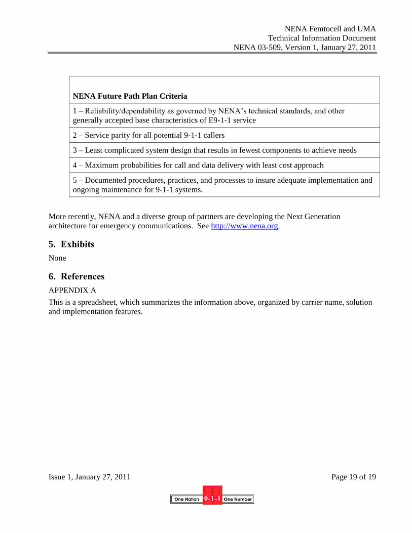
NENA Future Path Plan Criteria
1 – Reliability/dependability as governed by NENA’s technical standards, and other
generally accepted base characteristics of E9-1-1 service
2 – Service parity for all potential 9-1-1 callers
3 – Least complicated system design that results in fewest components to achieve needs
4 – Maximum probabilities for call and data delivery with least cost approach
5 – Documented procedures, practices, and processes to insure adequate implementation and
ongoing maintenance for 9-1-1 systems.
More recently, NENA and a diverse group of partners are developing the Next Generation
architecture for emergency communications. See http://www.nena.org.
5. Exhibits
None
6. References
APPENDIX A
This is a spreadsheet, which summarizes the information above, organized by carrier name, solution
and implementation features.