Embed Size (px)
DESCRIPTION
FEM
Citation preview

7/14/2019 Femb27pc Tutor
http://slidepdf.com/reader/full/femb27pc-tutor 1/34
FEMB PC Training Manual Version 27 1
eta/FEMB-PC(Finite Element Model Builder)
Version 27
TRAINING MANUAL
A pre- and post-processor for use with
LS-DYNA
September 2001
Windows 98/ NT 4/ 2000

7/14/2019 Femb27pc Tutor
http://slidepdf.com/reader/full/femb27pc-tutor 2/34
FEMB PC Training Manual Version 27 2
FORWARD
The concepts, methods, and examples presented in this text are for illustrative and educational
purposes only, and are not intended to be exhaustive or to apply to any particular engineering problemor design.
This material is a compilation of data and figures from many sources.
Engineering Technology Associates, Inc. assumes no liability or responsibility to any person or company for direct or indirect damages resulting from the use of any information contained herein.
Engineering Technology Associates, Inc., eta, the eta logo, eta/FEMB-PC, and the eta/FEMB-PC logoare the registered trademarks of Engineering Technology Associates, Inc.
Copyright 2001 Engineering Technology Associates, Inc. All rights reserved.
Engineering Technology Associates, Inc.
1133 E. Maple Rd., Suite 200
Troy, MI 48083-2896
Phone: (248) 729 - 3010
FAX: (248) 729 - 3020
Support: (800) eta – 3362

7/14/2019 Femb27pc Tutor
http://slidepdf.com/reader/full/femb27pc-tutor 3/34
FEMB PC Training Manual Version 27 3
FEMB27-PC Tutorial Introduction
Tutorial-1, Bumper Model
A half-bumper symmetry model with an initial velocity is crashed against a rigid wall.This tutorial presents line mesh and automesh techniques for plate/shell modeling.
Tutor ial-2, LS-DYNA Example Manual pg-55
Two overlapping plates are connected using spotwelds and the plates are pulled apart.
This tutorial presents three techniques for plate/shell modeling:
§ Creating Elements by Line Data Meshing
§ Creating Elements by Node Definition§ Creating Elements By Extrusion
Most dynamic FEA models require a 5-step setup procedure (pre-process):
1- Modeling
2- Material3- Property
4- Contact5- BC
This 5 step procedure will be followed in all the tutorial cases.

7/14/2019 Femb27pc Tutor
http://slidepdf.com/reader/full/femb27pc-tutor 4/34
FEMB PC Training Manual Version 27 4
Tutorial-1, Bumper Model
A symmetrical half-bumper symmetry model with an initial velocity is crashed against a rigid wall.This tutorial presents line mesh and automesh techniques for plate/shell modeling.
STEP-1, Modeling
Read-in (import) “tutor1.lin” (extension *.lin is FEMB line data file):
- FILE menu;
- IMPORT; select “tutor1.lin” file according to your path (in files of type box, select FembLine File, *.lin).
By default, Lines and Surfaces in the display options are toggled ON. Take the opportunity to switch
ON/OFF these options to explore the loaded CAD information. Also, use the free rotation, pan andzoom commands to explore the line data model. Click the database statistics option to verify the loaded
entities. Click the part dropdown menu (upper right corner) to verify the number of parts and toobserve the part color association.
Four part names will be displayed with their part-color association:
1- WALL2- BUMPER 3- PLATE
4- RAIL

7/14/2019 Femb27pc Tutor
http://slidepdf.com/reader/full/femb27pc-tutor 5/34
FEMB PC Training Manual Version 27 5
Saving as a FEMB database file (*.fmb):
- FILE menu;- click SAVE AS; input “tutor1” as File Name and *.fmb in the Save As Type box (choose
the location of the file as desired; the upper left corner of FEMB shows the actual FEMBdatabase file name).

7/14/2019 Femb27pc Tutor
http://slidepdf.com/reader/full/femb27pc-tutor 6/34
FEMB PC Training Manual Version 27 6
1.1- Creating elements by line data meshing:
Keep the part Wall on, switch all others off:
- PART menu (F2);- click KEEP; select WALL by clicking on the WALL part name in the data collector;
APPLY.
From the part dropdown menu, select WALL to make sure WALL is the current part. The “current part” is the active part in which all new entities (i.e., new elements) are created. In FEMB, the “current part” is the one showing at the top of the part list dropdown menu.
Before meshing, we need to know the length of the 4 lines that define the WALL. Using the
MEASURE/DISTANCE command (ruler icon in the tool bar), measure the lines by clicking on thecorners, this will show that the wall is 750x500 mm. In this case, we will create 50mm shell elements
by meshing 15 elements on the long side and 10 on the shorter side the part Wall.
Element mesh through 4-line mesh:
- ELEMENT menu (F6);- click PLATE/SOLID MESH; 4-LINE; select the 4 lines in the display window by clicking
on them;

7/14/2019 Femb27pc Tutor
http://slidepdf.com/reader/full/femb27pc-tutor 7/34
FEMB PC Training Manual Version 27 7
- insert 15,10 (which is the same as entering 15,10,15,10);- click YES to accept the mesh; select END to close the data collector.
Note: The orientation of line selection dictates the orientation (normal) of the elements to be createdaccording to the “right hand rule”.

7/14/2019 Femb27pc Tutor
http://slidepdf.com/reader/full/femb27pc-tutor 8/34
FEMB PC Training Manual Version 27 8
1.2- Creating elements by surface data automesh:
Turn on all the parts but the part Wall:
- PART menu (F2);- click ON/OFF; turn on all parts but Wall by clicking on the part name;
-
click CLOSE to exit the menu.
Measure the height of the bumper flange using the measure/distance command (ruler button), ~30.mm.
Normally, flanges require 2 layers of elements; this would suggest a mesh density (element size) of 15mm for our sub-system bumper model.
- ELEMENT menu (F6);- click PLATE/SOLID MESH; SURFACE MESH;
- click BY PART in the data collector; select parts Bumper, Plate, Rail by clicking on the part name; APPLY; APPLY;
- input 15 in the element size popup window;- toggle ON “Create elements in original parts” in the popup window (if not, all elements will
be created in the current part);
- change Min. internal angle (Quad) to 30; change Max. internal angle (Quad) to 150 (tominimize number of tri-elements);
- click YES to accept the mesh or remesh with a different mesh criteria.
Turn ON all parts and observe the element mesh result (toggle OFF lines and surfaces, shrink elements, rotate model).

7/14/2019 Femb27pc Tutor
http://slidepdf.com/reader/full/femb27pc-tutor 9/34
FEMB PC Training Manual Version 27 9
1.3 - Model integrity check:
After a model is completed, a check for the integrity of the developed model is required. Usually, thefirst check is Boundary Display, which will highlight the free edges of the model and possible
discontinuities (unconnected elements or other imperfections).
-
CHECK menu (F8);- click BOUNDARY DISPLAY; select MULTIPLE SURF.
Other options can be performed to check the mesh quality (warpage, internal angles, normals, etc).
Note: The most common discontinuity is when two neighboring elements in a mesh are connected totwo different nodes sharing the same location or in a small range of proximity instead of connected by
a single, common node. To fix this imperfection, use the function Check Coincident Node:
- NODE menu (F5);
- click CHECK COINCIDENT;- input TOLERANCE (range distance of nodes to be merged, i.e., 0.01 default);
- select the nodes to be verified using the data collector.

7/14/2019 Femb27pc Tutor
http://slidepdf.com/reader/full/femb27pc-tutor 10/34
FEMB PC Training Manual Version 27 10
1.4- Connectivity:
At this point, all parts in the “tutor1.lin” file are modeled and meshed but they are not connected.Usually parts are connected by 1-dimensional elements (rigid links or spotwelds).
Connecting parts by spotwelds:
First, create a new part called “spotweld”:
- PART menu (F2);- click CREATE PART; input “spotweld” for new part name;
- click OK to accept the default values and close the data collector.
Creating spotwelds:
- ELEMENT menu (F6);
- click CREATE; SPOTWELD;- switch data collector from POINT to NODE (if not already on NODE);- create the spotwelds (two node constraints) by selecting the proper nodes according to the
following picture:
§ 3 spotwelds on top and bottom of the plate connecting the plate and bumper parts
§ 8 spotwelds on each flange of the rail connecting the rail and plate parts
Note: Turn parts on/off per your convenience when defining the spotwelds.

7/14/2019 Femb27pc Tutor
http://slidepdf.com/reader/full/femb27pc-tutor 11/34
FEMB PC Training Manual Version 27 11
STEP-2, Material
Position the model:
- turn all parts on;- click the ISOMETRIC view button;
-
only ELEMENTS should be toggled on in the Display Options window.
Note: At this point the CAD information (points, lines, surfaces) has served its purpose and is no
longer necessary. The information can still remain in the database (toggling lines and surfaces on/off inthe View Options window), or it can be deleted from the database since a full FEA model has been
developed from the CAD data.
1- Material definition:
- MATERIAL menu (F9)
Once the material menu is selected FEMB enters the “material mode”. When in material mode thegraphic window displays parts with material colors instead of part colors. Since no materials have been
created and assigned yet, our model is displayed in gray.
In this tutorial, we want to define the part Wall as rigid material and the bumper components (Bumper,Plate, Rail) as elasto-plastic material.
- MATERIAL menu (F9);- click CREATE; STRUCTURAL
- select material 20.1.*MAT_RIGID from the structural material list (a new popup windowwill display for material definition)
Observe the form/profile of this window and its information:
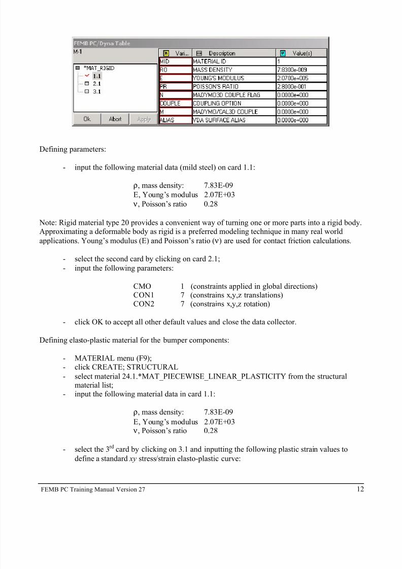
a) The left side of the popup window provides the LS-DYNA keyword material name (in thiscase, *MAT_RIGID) and the number of cards required for definition (in this case, 3 cards:1.1, 2.1 and 3.1). A check mark is displayed to indicate the active/selected card (in this case,
1.1). b) The adjacent column to the right, Variables, lists the variables for the active/selected card
(MID, ρ, E, ν, etc.).
c) The column Description provides a brief description of each variable.
d) The column Value contains the value defined for each variable.
7/14/2019 Femb27pc Tutor
http://slidepdf.com/reader/full/femb27pc-tutor 12/34
FEMB PC Training Manual Version 27 12
Defining parameters:
- input the following material data (mild steel) on card 1.1:
ρ, mass density: 7.83E-09
E, Young’s modulus 2.07E+03
ν, Poisson’s ratio 0.28
Note: Rigid material type 20 provides a convenient way of turning one or more parts into a rigid body.Approximating a deformable body as rigid is a preferred modeling technique in many real world
applications. Young’s modulus (E) and Poisson’s ratio ( ν) are used for contact friction calculations.
- select the second card by clicking on card 2.1;
- input the following parameters:
CMO 1 (constraints applied in global directions)
CON1 7 (constrains x,y,z translations)CON2 7 (constrains x,y,z rotation)
- click OK to accept all other default values and close the data collector.
Defining elasto-plastic material for the bumper components:
- MATERIAL menu (F9);- click CREATE; STRUCTURAL
- select material 24.1.*MAT_PIECEWISE_LINEAR_PLASTICITY from the structuralmaterial list;
- input the following material data in card 1.1:
ρ, mass density: 7.83E-09
E, Young’s modulus 2.07E+03 ν, Poisson’s ratio 0.28
- select the 3rd card by clicking on 3.1 and inputting the following plastic strain values to
define a standard xy stress/strain elasto-plastic curve:

7/14/2019 Femb27pc Tutor
http://slidepdf.com/reader/full/femb27pc-tutor 13/34
FEMB PC Training Manual Version 27 13
Effective Plastic Strain
1- 0.000E+002- 0.309E-013- 0.409E-01
4- 0.500E-015- 0.151E+00
6-
0.301E+007- 0.701E+008- 0.910E+00
- select the 4rd card by clicking on 4.1 and inputting the following stress values to define a
standard xy stress/strain elasto-plastic curve:
Stress Value @EPS#
1- 0.210E+032- 0.300E+03
3- 0.314E+034- 0.325E+035- 0.390E+03
6- 0.438E+037- 0.505E+03
8- 0.527E+03
- click OK to accept all other default values and close the data collector.
Checking the materials in a database:
- MATERIAL menu (F9);- click LIST.
The material list is shown according to MID (Material IDentification #) and material name. Two
materials are currently defined: MID-1 M1 and MID-2 M2. The “stop sign” indicates that the materialis not currently assigned to any part.
2- Assigning materials to parts:
- MATERIAL menu (F9);- click ASSIGN;- select material M1 (MAT_RIGID) by clicking on it;
- select part Wall by clicking on it; APPLY.
- click ASSIGN;- select material M2 (elasto-plastic) by clicking on it;- select the parts Bumper, Plate and Rail; APPLY.
After assigning the materials to the proper parts, the parts assume the material colors while in the
material menu.

7/14/2019 Femb27pc Tutor
http://slidepdf.com/reader/full/femb27pc-tutor 14/34
FEMB PC Training Manual Version 27 14
STEP-3, Properties
Position the model:
- turn all parts on;- click the ISOMETRIC view button;
-
only ELEMENTS should be toggled on in the Display Options window.
1- Property definition:
- PROPERTY menu (F10)
Once the property menu is selected FEMB enters the “property mode”. When in the property mode thegraphic window displays property colors instead of part colors. Since no properties are created and
assigned yet, our model is displayed in gray.
Creating a new property:
- PROPERTY menu (F10);
- click CREATE; SHELLS;- accept the default values for card 1.1; select the 2nd card by clicking on 2.1;
- input 1mm to T1, T2, T3 and T4 (constant 4 node thickness through the shell element);- click OK to accept all other default values and close the data collector.
For simplicity we will define all parts in this tutorial as 1mm thick. Later on, the user could make thisanalysis more interesting by assigning different thickness/properties to different parts (i.e., Wall=1mm,
Bumper=1mm, Plate=2mm, Rail=3mm).
Checking the properties in a database:
- PROPERTY menu (F10);
- click LIST.
The property list is shown according to SECID (SECtion property IDentification #) and property name.
One property is currently defined: SECID-1 P1. The “stop sign” indicates that the property is notcurrently assigned to any part.
2- Assigning properties to parts:
- PROPERTY menu (F10);- click ASSIGN;
- select property P1 (SECTION_SHELL, 1mm) by clicking on it;- select parts Wall, Bumper, Plate and Rail; APPLY.
After assigning the property to the proper parts, the parts assume the property part color.
7/14/2019 Femb27pc Tutor
http://slidepdf.com/reader/full/femb27pc-tutor 15/34
FEMB PC Training Manual Version 27 15
STEP-4, Contact
Position the model:
- turn all parts on;- click the ISOMETRIC view button;
-
only ELEMENTS should be toggled on in the Display Options window.
1- Contact definition:
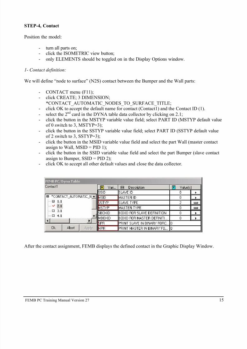
We will define “node to surface” (N2S) contact between the Bumper and the Wall parts:
- CONTACT menu (F11);- click CREATE; 3 DIMENSION;
*CONTACT_AUTOMATIC_NODES_TO_SURFACE_TITLE;- click OK to accept the default name for contact (Contact1) and the Contact ID (1).
- select the 2nd card in the DYNA table data collector by clicking on 2.1;- click the button in the MSTYP variable value field; select PART ID (MSTYP default value
of 0 switch to 3, MSTYP=3);
- click the button in the SSTYP variable value field; select PART ID (SSTYP default valueof 2 switch to 3, SSTYP=3);
- click the button in the MSID variable value field and select the part Wall (master contactassign to Wall, MSID = PID 1);
- click the button in the SSID variable value field and select the part Bumper (slave contact
assign to Bumper, SSID = PID 2);- click OK to accept all other default values and close the data collector.
After the contact assignment, FEMB displays the defined contact in the Graphic Display Window.

7/14/2019 Femb27pc Tutor
http://slidepdf.com/reader/full/femb27pc-tutor 16/34
FEMB PC Training Manual Version 27 16

7/14/2019 Femb27pc Tutor
http://slidepdf.com/reader/full/femb27pc-tutor 17/34
FEMB PC Training Manual Version 27 17
STEP-5, BC
Position the model:
- turn all parts on but Wall;- click the TOP (xy) view button;
-
only ELEMENTS should be toggled on in the Display Options window.
1- Boundary Condition Definition:
- BC menu (F12);
- click BOUNDARY; SPC; CREATE; NODE
We want to define the symmetry boundary condition for the half bumper mode, which in this case is
the xy plane (constraint in Y-translation, constraint in X,Z-rotationà SPC=2,4,6). We can define theconstraint for translation and rotation by toggling on the specific parameters in the popup window or
by selecting the symmetry plane.
- toggle on Y-translation and X, Z-rotation, or, click SYMMETRY and select XZ plane; OK;- select the nodes in the Bumper part in the symmetry plane (nodes in the lower edge of the
Bumper as displayed in top view).

7/14/2019 Femb27pc Tutor
http://slidepdf.com/reader/full/femb27pc-tutor 18/34
FEMB PC Training Manual Version 27 18

7/14/2019 Femb27pc Tutor
http://slidepdf.com/reader/full/femb27pc-tutor 19/34
FEMB PC Training Manual Version 27 19
2- Initial Condition Definition:
Position the model:
- turn all parts on but Wall;- click the TOP (xy) view button;
-
only ELEMENTS should be toggled on in the Display Options window.
Defining Initial Conditions:
- BC menu (F12);
- click INITIAL COND; VELOCITY; CREATE; NODE;- input Vx= -2234.7 (5 mph);- select parts Bumper, Plate and Rail; APPLY; APPLY;
- CANCEL to finish the command.

7/14/2019 Femb27pc Tutor
http://slidepdf.com/reader/full/femb27pc-tutor 20/34
FEMB PC Training Manual Version 27 20
Exporting (outputting) an LS-DYNA Input File:
All 5 steps are now concluded (modeling, material, property, contact, BC) and we are ready to wrap-upfor the analyses. The following section describes how to generate the desired output databases for post-
processing.
The LS-DYNA Miscellaneous drop down menu handles the non-graphical/numerical parameters of LS-DYNA (i.e., control termination time, database selection, box definition, etc.). At this point, wemust define the termination time and output database files.
Control cards:
- DYNAMISC menu;- click CONTROL;
- select TERMINATION by clicking into; click DEFINE;- input ENDTIM=0.060 sec (60 msec); accept the default for the other variables;
- click APPLY to accept the data; click OK to close the data collector (TERMINATION flagwill switch from NO to YES);
- click CLOSE to exit the Control Window list.
Database binary:
- click DATABASE; BINARY;- select D3PLOT by clicking on it; click DEFINE;
- input DT=0.006 sec (6 msec); accept the other default variables;- click APPLY to accept the data; click OK to close the data collector (D3PLOT flag will
switch from NO to YES);- click CLOSE to exit the Database Binary window list.
Database ASCII:
- click DATABASE; ASCII;- select GLSTAT by clicking on it; click DEFINE;- input DT=0.0008 sec (0.8 msec);
- click APPLY to accept the data; click OK to close the data collector (GLSTAT flag willswitch from NO to YES);
- click CLOSE to exit the Database ASCII window list.
With the above control card definition, we specify the analysis to run 60 msec, the GLSTAT file will
be written 75 times (60/0.8=75) and the D3PLOT file will be written 10 times (60/0.6=10). Thenumber of times that the D3PLOT file is written is equivalent to the number of animation frames in
post-processing (PostGL).
We are now ready to write out an LS-DYNA input deck. First, we will check the units:
- ANALYSIS menu;- click SETUP ANALYSIS;- in the Analysis Unit dropdown menu select MM, TON, SEC, N;

7/14/2019 Femb27pc Tutor
http://slidepdf.com/reader/full/femb27pc-tutor 21/34
FEMB PC Training Manual Version 27 21
- click OK to close the popup window.
- FILE menu;- select EXPORT;
- input “tutor1” in the File Name box (or other); LS-DYNA File (*.dyn) in the Save As Type box;;
-
click SAVE.
“tutor1.dyn” will be saved and ready for LS-DYNA processing. Take the opportunity to open this file
in your text editor of choice to get familiar with the LS-DYNA keyword structure.

7/14/2019 Femb27pc Tutor
http://slidepdf.com/reader/full/femb27pc-tutor 22/34
FEMB PC Training Manual Version 27 22
Tutorial-2, LS-DYNA Example Manual: *CONSTRAINED_SPOTWELD (pg-55)
Two overlapping plates are connected using spotwelds and the plates are pulled apart.This tutorial presents three techniques for plate/shell modeling:
§ Creating Elements by Line Data Meshing
§ Creating Elements by Node Definition
§ Creating Elements By Extrusion
Note: Use the FILL and ROTATE command during the tutorial to center the nodes (or other entities)in your screen. Also, circumstances may require that the REDRAW command be used.

7/14/2019 Femb27pc Tutor
http://slidepdf.com/reader/full/femb27pc-tutor 23/34
FEMB PC Training Manual Version 27 23
STEP-1, Modeling
1.1- Create a Shell Element Plate 8x4
Entities (lines, elements, etc.) will always be assigned to a part. Therefore, before creating entities,create a part:
- PART menu (F2);- click create PART;
- in the popup window input a part name, or accept the default (Part-1);
- accept the default part parameters in the DYNA Table window by clicking OK (after that,you can observe the new part as “current” in the part dropdown list in the upper right corner of FEMB).
OPTION-1 Create Elements by Li ne Data Meshing
In this approach, line data is generated or loaded (CAD data). The element mesh is generated on the
CAD geometry.
Assuming an empty database with the current part, Part-1:
1- Line Definition:
- LINE menu (F3);
- click CREATE, LINE(S);- key-in 0,0,0 and 0,40,0 for the new line coordinates, CREATE, END;- LINE menu (F3), COPY, TRANSLATE;
- select the line by clicking on it, or SELECT ALL in the data collector;

7/14/2019 Femb27pc Tutor
http://slidepdf.com/reader/full/femb27pc-tutor 24/34
FEMB PC Training Manual Version 27 24
- click TRANSLATE, GLOBAL;
- input 80,0,0,1 in the popup window (copy line through x incremental spacing 80, 1 time);- answer YES to the “Include copied element in its original part?” popup window prompt;- END to close data collector.
At this point, the two generated lines already define our plate geometry. They allow us to generate
elements with the 2-line mesh command as follows. The CAD data could be completed if desired and a4-line mesh used.
2- Element Definition:
- ELEMENT menu (F6);- click PLATE/SOLID MESH, 2-LINE MESH;- select the 2 lines by clicking on them;
- input 4,8 (equivalent to 4,8,4,8), accept mesh by clicking YES;- END to close the data collector.
OPTION-2 Create Elements by Node Definition
In this approach, we generate elements by defining and selecting nodes. Nodes are generated at definedcoordinates and then copied/translated to define a mesh.
1- Node Definition:
- NODE menu (F5);- click CREATE, AT COORD (a FEMB data collector window will open for coordinate
definition);
- in the data collector window click KEY IN, insert 0,0,0 ( tab,tab,enter);- click CREATE, END (a node will be created at the origin).
- in the NODE menu (F5);- click COPY, TRANSLATE, (the FEMB data collector window will open for node
selection and translation input) *;- select the node at the origin by clicking directly on the node, or click SELECT ALL (the
selected node will be highlighted);- click TRANSLATE, GLOBAL;- enter 0,10,0,4 in the popup screen (copy node through y incremental spacing 10, 4 times);
- click END to close the collector window.
Another way to define the 5 nodes above:
- NODE menu (F5);
- click CREATE, AT COORD;- input 0,0,0 and 0,40,0 in the collector window to create 2 nodes at these coordinates;
- still in the CREATE NODE submenu, select BETWEEN 2 COORD.;- switch the data collector from POINT to NODE and click directly on the 2 nodes in the
graphic display window;
7/14/2019 Femb27pc Tutor
http://slidepdf.com/reader/full/femb27pc-tutor 25/34
FEMB PC Training Manual Version 27 25
- enter 3 to generate 3 nodes between the selected nodes;
- click END to close collector window.
At this point we have 5 nodes in the y direction spaced by 10. We will copy these 5 nodes along the xy
plane to generate shell elements with them:
-
NODE menu (F5);- click COPY, TRANSLATE;- select the 5 nodes BY REGION/DRAG WINDOW from the data collector, or SELECT
ALL;- click TRANSLATE, GLOBAL;
- input 10,0,0,1 in the popup window (copy nodes through x incremental spacing 10, 1 time);- click END to close the collector window.
We now have 10 nodes for element definition. Note that the number of nodes and elements can always be verified by observing the lower right edge
of the FEMB interface.
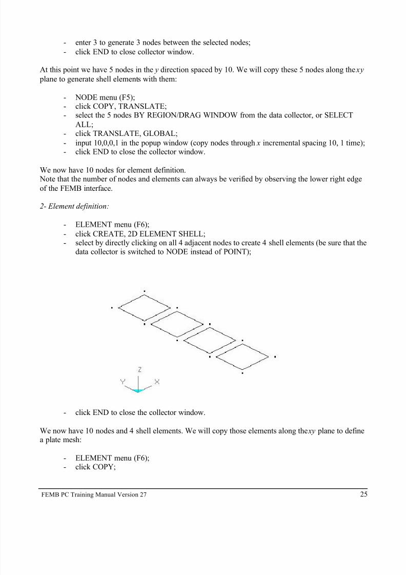
2- Element definition:
- ELEMENT menu (F6);
- click CREATE, 2D ELEMENT SHELL;- select by directly clicking on all 4 adjacent nodes to create 4 shell elements (be sure that the
data collector is switched to NODE instead of POINT);
- click END to close the collector window.
We now have 10 nodes and 4 shell elements. We will copy those elements along the xy plane to definea plate mesh:
- ELEMENT menu (F6);- click COPY;

7/14/2019 Femb27pc Tutor
http://slidepdf.com/reader/full/femb27pc-tutor 26/34
FEMB PC Training Manual Version 27 26
- click CURRENT PART in the data collector to select all 4 elements (other options to select
all 4 elements through the data collector are also available), APPLY- click MOVE, INCREMENTAL;- input 10,0,0,7 in the popup window (copy elements through x incremental spacing 10, 7
times), GLOBAL;- answer YES to the “Include copied element in its original part?” popup window prompt;
-
END to close the data collector.
We now have 80 nodes and 32 elements defining a plate mesh.
OPTION-3 Create Elements by Extrusion
In this approach, the 2-D plate mesh will be generated by the extrusion of 1-D elements. Later, we willalso use this technique to extrude 3-D solids from 2-D plates. In summary, 1-D elements can be
extruded to 2-D shell elements, and 2-D shell elements can be extruded to 3-D solid elements. Elementextrusion is also known as “drag mesh”.
Assuming an empty database with the current part, Part-1:
1- Node Definition (5 node definition as before):
- NODE menu (F5);
- click CREATE, AT COORD (a FEMB data collector window will open for coordinatedefinition);
- in the data collector window click KEY IN, insert 0,0,0 ( tab,tab,enter);- click CREATE, END (a node will be created at the origin).
- in the NODE menu (F5);- click COPY, TRANSLATE, (a FEMB data collector window will open for node selection
and translation input);- select the node at the origin by clicking directly on the node, or click SELECT ALL (the
selected node will be highlighted);
- click TRANSLATE, GLOBAL;- input 0,10,0,4 in the popup screen (copy the node through y incremental spacing 10mm, 4
times);- click END to close the collector window.
We will generate an extra node for local coordinate definition (for extrusion purposes later);
- NODE menu (F5);- click COPY, TRANSLATE, (a FEMB data collector window will open for node selection
and translation input);
- select node 1 (the node at the origin) by clicking on it;- click TRANSLATE, GLOBAL;
- input 0,0,10,1 in the popup window (copy the node through z incremental spacing 10mm, 1time).

7/14/2019 Femb27pc Tutor
http://slidepdf.com/reader/full/femb27pc-tutor 27/34
FEMB PC Training Manual Version 27 27
2- 1D Element Definition:
- ELEMENT menu (F6);- click CREATE, PLOTEL;
- select the nodes in sequence to generate four 1-D elements (for better viewing, toggleSHRINK on in the Display Options Window).
3- Element Extrusion (1-D to 2-D):
- ELEMENT menu (F6);- click DRAG MESH, TRANSLATIONAL;
- select the four 1-D elements by clicking on them (or another option from the data collector),APPLY;
- click DEFINE coordinate system;
- select three nodes for local coordinate system definition by first clicking on the one at theorigin, then any in the y direction, and then the one in the z direction (the local coordinate
system will display; the mesh will be generated according to the w local coordinatedirection);
- input 80 in the popup window for the drag mesh distance along w axis;
- input 8 in the popup window for the number of layers along w axis;- click YES to accept the mesh.
The 1-D elements have served their purpose and are no longer necessary. Delete the 1-D elements withthe DELETE function in the ELEMENT menu (F6).
7/14/2019 Femb27pc Tutor
http://slidepdf.com/reader/full/femb27pc-tutor 28/34
FEMB PC Training Manual Version 27 28
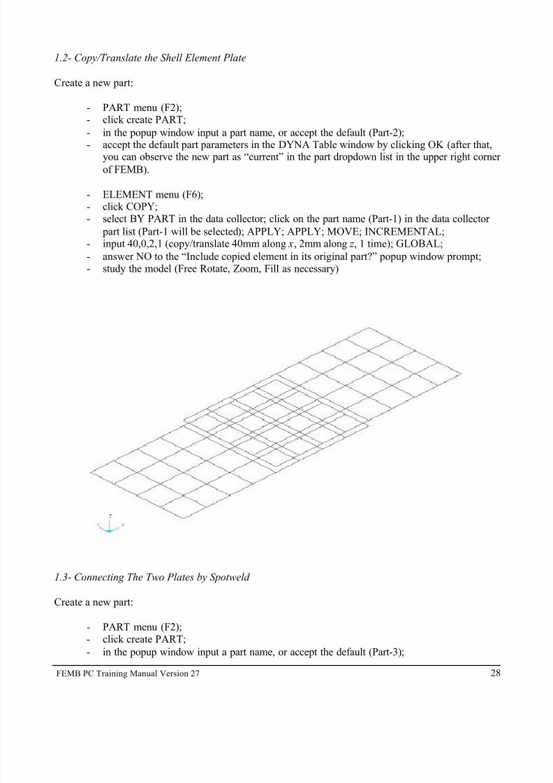
1.2- Copy/Translate the Shell Element Plate
Create a new part:
- PART menu (F2);- click create PART;
-
in the popup window input a part name, or accept the default (Part-2);- accept the default part parameters in the DYNA Table window by clicking OK (after that,you can observe the new part as “current” in the part dropdown list in the upper right corner
of FEMB).
- ELEMENT menu (F6);- click COPY;- select BY PART in the data collector; click on the part name (Part-1) in the data collector
part list (Part-1 will be selected); APPLY; APPLY; MOVE; INCREMENTAL;- input 40,0,2,1 (copy/translate 40mm along x, 2mm along z , 1 time); GLOBAL;
- answer NO to the “Include copied element in its original part?” popup window prompt;- study the model (Free Rotate, Zoom, Fill as necessary)
1.3- Connecting The Two Plates by Spotweld
Create a new part:
- PART menu (F2);- click create PART;
- in the popup window input a part name, or accept the default (Part-3);

7/14/2019 Femb27pc Tutor
http://slidepdf.com/reader/full/femb27pc-tutor 29/34
FEMB PC Training Manual Version 27 29
- accept the default part parameters in the DYNA Table window by clicking OK (after that,
you can observe the new part as “current” in the part dropdown list in the upper right corner of FEMB).
- ELEMENT menu (F6);- click CREATE; SPOTWELD;
-
click directly on the nodes to generate the spotweld elements as in the following figure(make sure that the data collector is toggled on NODE, not POINT);- click END to close the collector window.
The modeling step is done, the next step is to assign material to the parts.
STEP-2, Material
- MATERIAL menu (F9)
Once in material mode the graphic window displays material colors instead of part colors. Since nomaterials are created yet, our model is displayed in gray.
Defining materials:
- click CREATE in the material menu;- select STRUCTURAL;- select material 3.1*MAT_PLASTIC_KINEMATIC;
- input the following values to the proper material variables:

7/14/2019 Femb27pc Tutor
http://slidepdf.com/reader/full/femb27pc-tutor 30/34
FEMB PC Training Manual Version 27 30
Ro = 2.70E-6E = 68.9Pr = 0.33
Sigy = 0.286Etan = 0.00689
- click APPLY to accept the data; click OK to close the data collector.
Material 1 (default name M-1) is created and can be observed by clicking LIST in the material menu. Now we’ll assign the material to the proper parts.
- click ASSIGN in the material menu;- select the material (M-1) by clicking directly on the material part list;
- click ON PARTS in the data collector; APPLY.
STEP-3, Properties
- PROPERTY menu (F10)
Once in the property mode the graphic window displays property colors instead of part colors. Sinceno properties have been created or assigned yet the model is displayed in gray.
Defining materials:
- click CREATE in the property menu;- select SHELLS;- input the following values for these property variables:
Elform= 6 (S/R Hughes-Liu)
Nip = 3
- select the next card by clicking on 2.1 in the left column of the data collector;
- input the following values for these variables:
T1 = 2T2 = 2T3 = 2
T4 = 2
- click APPLY to accept the data; click OK to close the data collector.
Property 1 (default name P-1) is created and can be observed by clicking LIST in the property menu.
Now we will assign the property.
- click ASSIGN in the property menu;- select the property (P-1) by clicking directly on the property part list;- click ON PARTS in the data collector; APPLY.
7/14/2019 Femb27pc Tutor
http://slidepdf.com/reader/full/femb27pc-tutor 31/34
FEMB PC Training Manual Version 27 31
STEP-4, Contact
- CONTACT menu (F11);- click CREATE; select 3 DIMENSION; select
*CONTACT_AUTOMATIC_SINGLE_SURFACE_TITLE;- click OK to accept the default value for Contact Name and Contact ID;- click OK to accept the default value (“0”) for all cards (the message window displays: “All
segments are included for single surface contact”)
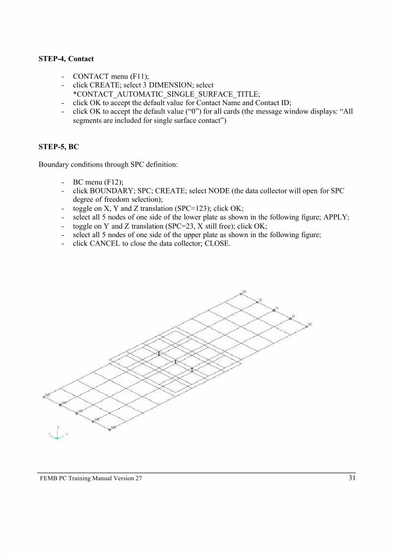
STEP-5, BC
Boundary conditions through SPC definition:
- BC menu (F12);- click BOUNDARY; SPC; CREATE; select NODE (the data collector will open for SPC
degree of freedom selection);
- toggle on X, Y and Z translation (SPC=123); click OK;- select all 5 nodes of one side of the lower plate as shown in the following figure; APPLY;
- toggle on Y and Z translation (SPC=23, X still free); click OK;- select all 5 nodes of one side of the upper plate as shown in the following figure;- click CANCEL to close the data collector; CLOSE.

7/14/2019 Femb27pc Tutor
http://slidepdf.com/reader/full/femb27pc-tutor 32/34
FEMB PC Training Manual Version 27 32
Initial conditions/load by velocity definition on one end of the plate:
First, we must define a node set:
- SET menu (F7);- click NODE; CREATE; OK to accept the default Set Name and Set ID;
-
select all 5 nodes on the edge of the upper plate previously defined by SPC=23 (not the one previously defined by SPC=123); APPLY.
Then, define a load curve:
- DYNAMISC menu;- click LOAD CURVE; CREATE; OK to accept the default load curve name; OK to accept
the default values for the load curve parameters;
- input (click INSERT; select KEY-IN) the following XY data for abscissa and ordinatecurve definition;
X Y0. 0.
10. 0.304820. 0.3048
- click OK to close the load curve data collector; CLOSE;
Prescribed motion definition:
- BC menu (F12);- click BOUNDARY; PRESCRIBED MOTION; CREATE; NODE SET;- in the DYNA Table collector window click on Edit Model button in the NSID value field
(top right corner of the window) and select Node Set 1 by clicking on it;- click on the DOF Enumerated button and select X-TRANSLATION;
- click on the LCID Edit Model button and select LCur 1 by clicking on it (the abovevariables should look like the following picture);
- click APPLY to accept the data; click OK to close the data collector.

7/14/2019 Femb27pc Tutor
http://slidepdf.com/reader/full/femb27pc-tutor 33/34
FEMB PC Training Manual Version 27 33
All 5 steps are now concluded (modeling, material, property, contact, BC) and we are ready to wrap-up
for the analyses. The following section describes how to generate the desired output databases for post- processing.
- DYNAMISC menu;
Control cards:
- click CONTROL;
- select TERMINATION by clicking on it; click DEFINE;- input HGEN=8.00; accept the default values for the other variables;
- click APPLY to accept the data; click OK to close the data collector (TERMINATION flagwill switch from NO to YES);
- select ENERGY by clicking on it; click DEFINE;
- input HGEN=2, SLNTEN=2; accept the default values for the other variables;- click APPLY to accept the data; click OK to close the data collector (ENERGY flag will
switch from NO to YES);- select OUTPUT by clicking on it; click DEFINE;- in the NPOPT value dropdown select “NODAL COORDINATES…” (NPOPT=1); in the
NEECHO value dropdown select “BOTH NODE AND ELEMENT..” (NEECHO=3);accept the default values for the other variables;
- click APPLY to accept the data; click OK to close the data collector (OUTPUT flag willswitch from NO to YES);
- select SHELL by clicking on it; click DEFINE;
- in the ISTUPID value dropdown select “MEMBRANE…” (ISTUPID=1); accept the defaultvalues for the other variables;
- click APPLY to accept the data; click OK to close the data collector (SHELL flag willswitch from NO to YES);
- click CLOSE to exit the Control Window list.
Database binary:
- click DATABASE; BINARY;- select D3PLOT by clicking on it; click DEFINE;
- input DT=2; accept the default values for the other variables;- click APPLY to accept the data; click OK to close the data collector (D3PLOT flag will
switch from NO to YES);- select D3THDT by clicking on it; click DEFINE;- input DT=99999; accept the default values for the other variables;
- click APPLY to accept the data; click OK to close the data collector (D3THDT flag willswitch from NO to YES);
- click CLOSE to exit the Database Binary Window list.
Database ASCII:
- click DATABASE; ASCII;
- select GLSTAT by clicking on it; click DEFINE;- input DT=0.010;

7/14/2019 Femb27pc Tutor
http://slidepdf.com/reader/full/femb27pc-tutor 34/34
- click APPLY to accept the data; click OK to close the data collector (GLSTAT flag will
switch from NO to YES);- select MATSUM by clicking on it; click DEFINE;- input DT=0.010;
- click APPLY to accept the data; click OK to close the data collector (MATSUM flag willswitch from NO to YES);
-
select NODFOR by clicking on it; click DEFINE;- input DT=0.010;- click APPLY to accept the data; click OK to close the data collector (NODFOR flag will
switch from NO to YES);- select NODOUT by clicking on it; click DEFINE;
- input DT=0.010;- click APPLY to accept the data; click OK to close the data collector (NODOUT flag will
switch from NO to YES);
- select SECFOR by clicking on it; click DEFINE;- input DT=0.010;
- click APPLY to accept the data; click OK to close the data collector (SECFOR flag willswitch from NO to YES);
- click CLOSE to exit the Database ASCII window list.
We are now ready to write out an LS-DYNA input deck. First, we will check the units:
- ANALYSIS menu;
- click SETUP ANALYSIS;- in the Analysis Unit dropdown menu select MM, KG, MSEC, KN;
- click OK to close the popup window.
- FILE menu;- select EXPORT;
- input “tutor1” in the File Name box (or other); LSDYNA File (*.dyn) in the Save As Type box;;
- click SAVE.
“tutor1.dyn” will be saved and is ready for LS-DYNA processing. Take the opportunity to open this
file in your text editor of choice to get familiar with the LS-DYNA keyword file structure.

![Game Based Carrom Tutor - CSE, IIT Bombaysri/students/mrinal-slides.pdf · IntroductionCarrom Tutor 1.0Carrom Tutor 2.0User Experiments Game Based Carrom Tutor Mayur Katke [123050069]](https://img.pdfslide.us/doc/110x75/5abb96027f8b9a567c8ccbad/game-based-carrom-tutor-cse-iit-bombay-sristudentsmrinal-tutor-10carrom-tutor.jpg)