Embed Size (px)
Citation preview
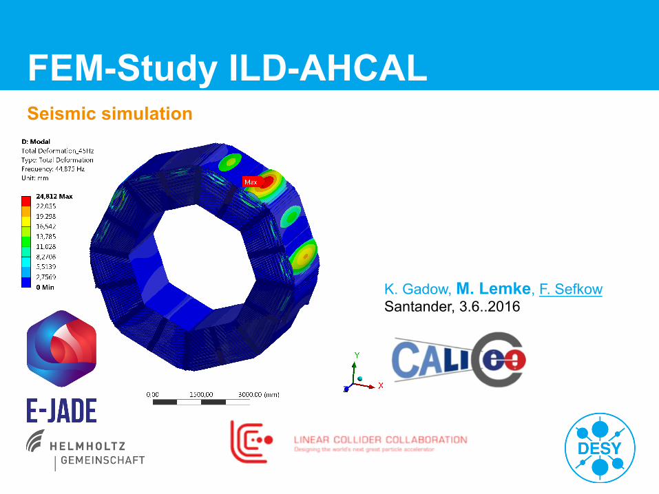
FEM-Study ILD-AHCAL Seismic simulation
K. Gadow, M. Lemke, F. Sefkow Santander, 3.6..2016
Martin Lemke | FEM-Study ILD-AHCAL | 11. 03. 2016| Seite 2
Overview
> Reminder of earlier studies
> Sub-structuring method
> First results
> Outlook
Martin Lemke | FEM-Study ILD-AHCAL | 11. 03. 2016| Seite 3
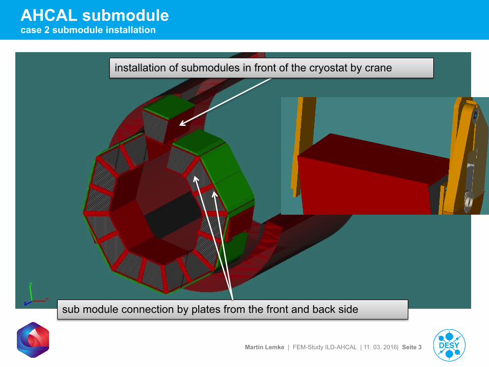
AHCAL submodule case 2 submodule installation
installation of submodules in front of the cryostat by crane
sub module connection by plates from the front and back side
Martin Lemke | FEM-Study ILD-AHCAL | 11. 03. 2016| Seite 4
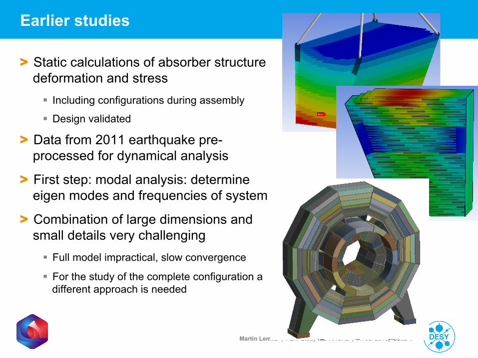
Earlier studies
> Static calculations of absorber structure deformation and stress § Including configurations during assembly
§ Design validated
> Data from 2011 earthquake pre-processed for dynamical analysis
> First step: modal analysis: determine eigen modes and frequencies of system
> Combination of large dimensions and small details very challenging § Full model impractical, slow convergence
§ For the study of the complete configuration a different approach is needed
Martin Lemke | FEM-Study ILD-AHCAL | 11. 03. 2016| Seite 5
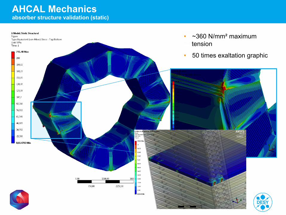
AHCAL Mechanics absorber structure validation (static)
• ~360 N/mm² maximum tension
• 50 times exaltation graphic
Martin Lemke | FEM-Study ILD-AHCAL | 11. 03. 2016| Seite 6
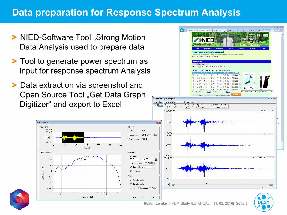
Data preparation for Response Spectrum Analysis
> NIED-Software Tool „Strong Motion Data Analysis used to prepare data
> Tool to generate power spectrum as input for response spectrum Analysis
> Data extraction via screenshot and Open Source Tool „Get Data Graph Digitizer“ and export to Excel
Martin Lemke | FEM-Study ILD-AHCAL | 11. 03. 2016| Seite 7
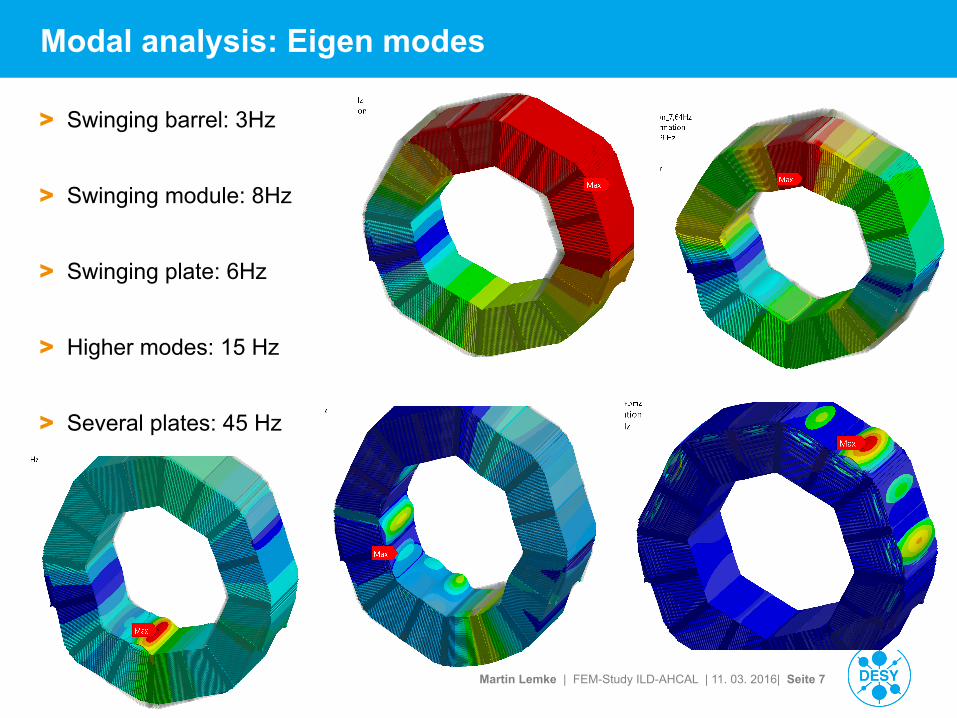
Modal analysis: Eigen modes
> Swinging barrel: 3Hz
> Swinging module: 8Hz
> Swinging plate: 6Hz
> Higher modes: 15 Hz
> Several plates: 45 Hz
Martin Lemke | FEM-Study ILD-AHCAL | 11. 03. 2016| Seite 8
Appropiate calculation method for complex structures
> First tests with a substitution method for the complex AHCAL-Segments with effective material parameters (effective elastic modules and sheer modules, as well as effective Poisson's ratio) in combination with a homogeneous body as a replacement for the detailed AHCAL-Segment => unfortunately no real breakthrough
> Another way to calculate such a complex model like the AHCAL-Structure had to be found …
> The chosen calculation method is the Substructuring Method and hereby especially the Component Mode Synthesis (CMS) as a form of substructure coupling analysis in ANSYS used in structural dynamics
> Built up test cases in ANSYS to develop the APDL-Command-Snippets (handling geometry/model, combine result-files)
Martin Lemke | FEM-Study ILD-AHCAL | 11. 03. 2016| Seite 9
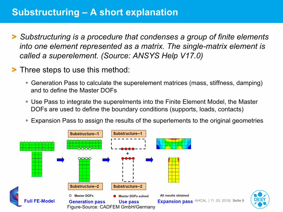
Substructuring – A short explanation
> Substructuring is a procedure that condenses a group of finite elements into one element represented as a matrix. The single-matrix element is called a superelement. (Source: ANSYS Help V17.0)
> Three steps to use this method: § Generation Pass to calculate the superelement matrices (mass, stiffness, damping)
and to define the Master DOFs
§ Use Pass to integrate the superelments into the Finite Element Model, the Master DOFs are used to define the boundary conditions (supports, loads, contacts)
§ Expansion Pass to assign the results of the superlements to the original geometries
Figure-Source: CADFEM GmbH/Germany
Martin Lemke | FEM-Study ILD-AHCAL | 11. 03. 2016| Seite 10
Geometry Preparation
Static Analysis
Modal Analysis
Response Spectrum Analysis
View Results
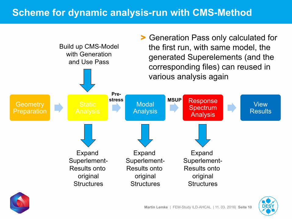
Scheme for dynamic analysis-run with CMS-Method
Build up CMS-Model with Generation and Use Pass
MSUP
Expand Superlement- Results onto
original Structures
Expand Superlement- Results onto
original Structures
Expand Superlement- Results onto
original Structures
Pre-stress
> Generation Pass only calculated for the first run, with same model, the generated Superelements (and the corresponding files) can reused in various analysis again
Martin Lemke | FEM-Study ILD-AHCAL | 11. 03. 2016| Seite 11
Substructuring – Pros and Cons
> Pro: § Complex models can be calculated, n-Elements describing the complex FE-model
can be simplified with the CMS-method to one! single element
§ For same geometry/mesh, the created files for super-elements can be saved/reused (huge time saving potential)
§ Very good performance (with reusing super-element-Files) in dynamic analysis
§ Less relevant eigen modes can be sorted out by filtering the calculated modes with APDL-Commands
> Contra: § Long time to simplify geometry / to prepare the Finite Element Model
§ Long preparation/calculation time in Generation Pass and Expansion Pass (these are additional calculations to the real model/analysis) => BUT: very effective in complex models with several analysis steps
§ APDL (ANSYS Parametric Design Language) and FE-models around APDL-commands (sometimes) sensitive to handle ;-)
§ …
Martin Lemke | FEM-Study ILD-AHCAL | 11. 03. 2016| Seite 12
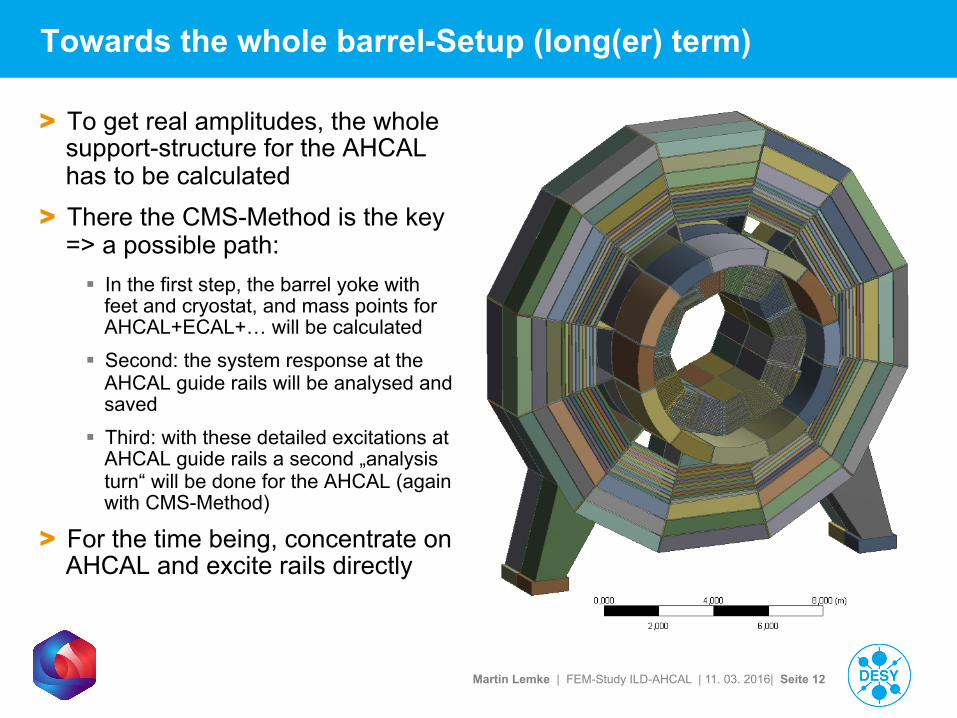
Towards the whole barrel-Setup (long(er) term)
> To get real amplitudes, the whole support-structure for the AHCAL has to be calculated
> There the CMS-Method is the key => a possible path:
§ In the first step, the barrel yoke with feet and cryostat, and mass points for AHCAL+ECAL+… will be calculated
§ Second: the system response at the AHCAL guide rails will be analysed and saved
§ Third: with these detailed excitations at AHCAL guide rails a second „analysis turn“ will be done for the AHCAL (again with CMS-Method)
> For the time being, concentrate on AHCAL and excite rails directly
Martin Lemke | FEM-Study ILD-AHCAL | 11. 03. 2016| Seite 13
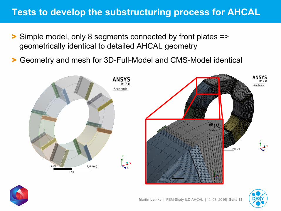
Tests to develop the substructuring process for AHCAL
> Simple model, only 8 segments connected by front plates => geometrically identical to detailed AHCAL geometry
> Geometry and mesh for 3D-Full-Model and CMS-Model identical
Martin Lemke | FEM-Study ILD-AHCAL | 11. 03. 2016| Seite 14
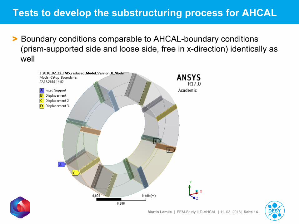
Tests to develop the substructuring process for AHCAL
> Boundary conditions comparable to AHCAL-boundary conditions (prism-supported side and loose side, free in x-direction) identically as well
Martin Lemke | FEM-Study ILD-AHCAL | 11. 03. 2016| Seite 15
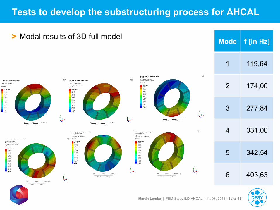
Tests to develop the substructuring process for AHCAL
> Modal results of 3D full model Mode f [in Hz]
1 119,64
2 174,00
3 277,84
4 331,00
5 342,54
6 403,63
Martin Lemke | FEM-Study ILD-AHCAL | 11. 03. 2016| Seite 16
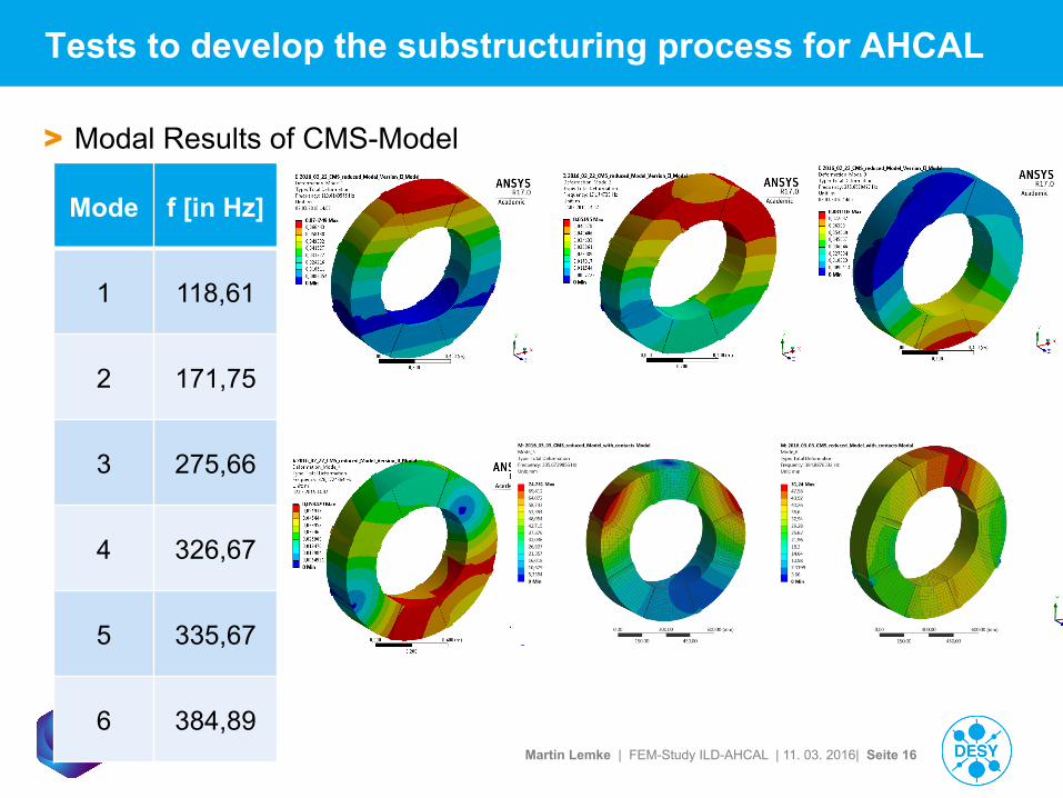
Tests to develop the substructuring process for AHCAL
> Modal Results of CMS-Model
Mode f [in Hz]
1 118,61
2 171,75
3 275,66
4 326,67
5 335,67
6 384,89
Martin Lemke | FEM-Study ILD-AHCAL | 11. 03. 2016| Seite 17
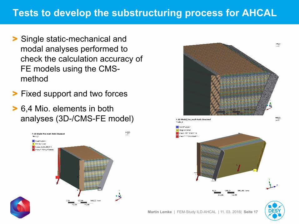
Tests to develop the substructuring process for AHCAL
> Single static-mechanical and modal analyses performed to check the calculation accuracy of FE models using the CMS-method
> Fixed support and two forces
> 6,4 Mio. elements in both analyses (3D-/CMS-FE model)
Martin Lemke | FEM-Study ILD-AHCAL | 11. 03. 2016| Seite 18
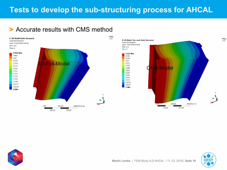
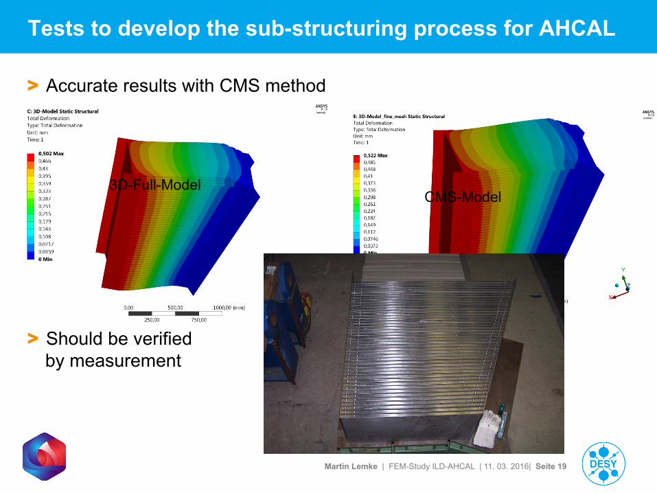
Tests to develop the sub-structuring process for AHCAL
> Accurate results with CMS method
3D-Full-Model CMS-Model
Martin Lemke | FEM-Study ILD-AHCAL | 11. 03. 2016| Seite 19
Tests to develop the sub-structuring process for AHCAL
> Accurate results with CMS method
3D-Full-Model CMS-Model
> Should be verified by measurement
Martin Lemke | FEM-Study ILD-AHCAL | 11. 03. 2016| Seite 20
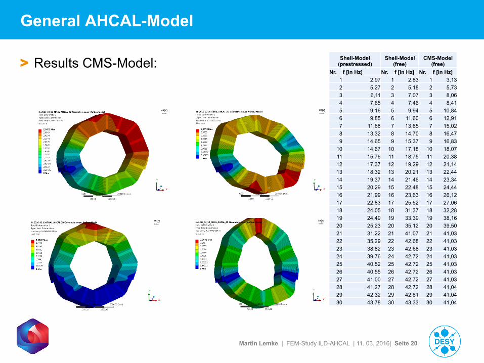
General AHCAL-Model
> Results CMS-Model: Shell-Model (prestressed)
Shell-Model (free)
CMS-Model (free)
Nr. f [in Hz] Nr. f [in Hz] Nr. f [in Hz]1 2,97 1 2,83 1 3,132 5,27 2 5,18 2 5,733 6,11 3 7,07 3 8,064 7,65 4 7,46 4 8,415 9,16 5 9,94 5 10,846 9,85 6 11,60 6 12,917 11,68 7 13,65 7 15,028 13,32 8 14,70 8 16,479 14,65 9 15,37 9 16,83
10 14,67 10 17,18 10 18,0711 15,76 11 18,75 11 20,3812 17,37 12 19,29 12 21,1413 18,32 13 20,21 13 22,4414 19,37 14 21,46 14 23,3415 20,29 15 22,48 15 24,4416 21,99 16 23,63 16 26,1217 22,83 17 25,52 17 27,0618 24,05 18 31,37 18 32,2819 24,49 19 33,39 19 38,1620 25,23 20 35,12 20 39,5021 31,22 21 41,07 21 41,0322 35,29 22 42,68 22 41,0323 38,82 23 42,68 23 41,0324 39,76 24 42,72 24 41,0325 40,52 25 42,72 25 41,0326 40,55 26 42,72 26 41,0327 41,00 27 42,72 27 41,0328 41,27 28 42,72 28 41,0429 42,32 29 42,81 29 41,0430 43,78 30 43,33 30 41,04
Martin Lemke | FEM-Study ILD-AHCAL | 11. 03. 2016| Seite 21
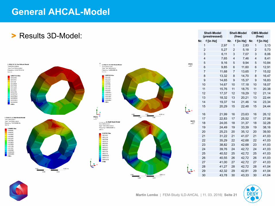
General AHCAL-Model
> Results 3D-Model: Shell-Model (prestressed)
Shell-Model (free)
CMS-Model (free)
Nr. f [in Hz] Nr. f [in Hz] Nr. f [in Hz]1 2,97 1 2,83 1 3,132 5,27 2 5,18 2 5,733 6,11 3 7,07 3 8,064 7,65 4 7,46 4 8,415 9,16 5 9,94 5 10,846 9,85 6 11,60 6 12,917 11,68 7 13,65 7 15,028 13,32 8 14,70 8 16,479 14,65 9 15,37 9 16,83
10 14,67 10 17,18 10 18,0711 15,76 11 18,75 11 20,3812 17,37 12 19,29 12 21,1413 18,32 13 20,21 13 22,4414 19,37 14 21,46 14 23,3415 20,29 15 22,48 15 24,44
16 21,99 16 23,63 16 26,1217 22,83 17 25,52 17 27,0618 24,05 18 31,37 18 32,2819 24,49 19 33,39 19 38,1620 25,23 20 35,12 20 39,5021 31,22 21 41,07 21 41,0322 35,29 22 42,68 22 41,0323 38,82 23 42,68 23 41,0324 39,76 24 42,72 24 41,0325 40,52 25 42,72 25 41,0326 40,55 26 42,72 26 41,0327 41,00 27 42,72 27 41,0328 41,27 28 42,72 28 41,0429 42,32 29 42,81 29 41,0430 43,78 30 43,33 30 41,04
Martin Lemke | FEM-Study ILD-AHCAL | 11. 03. 2016| Seite 22
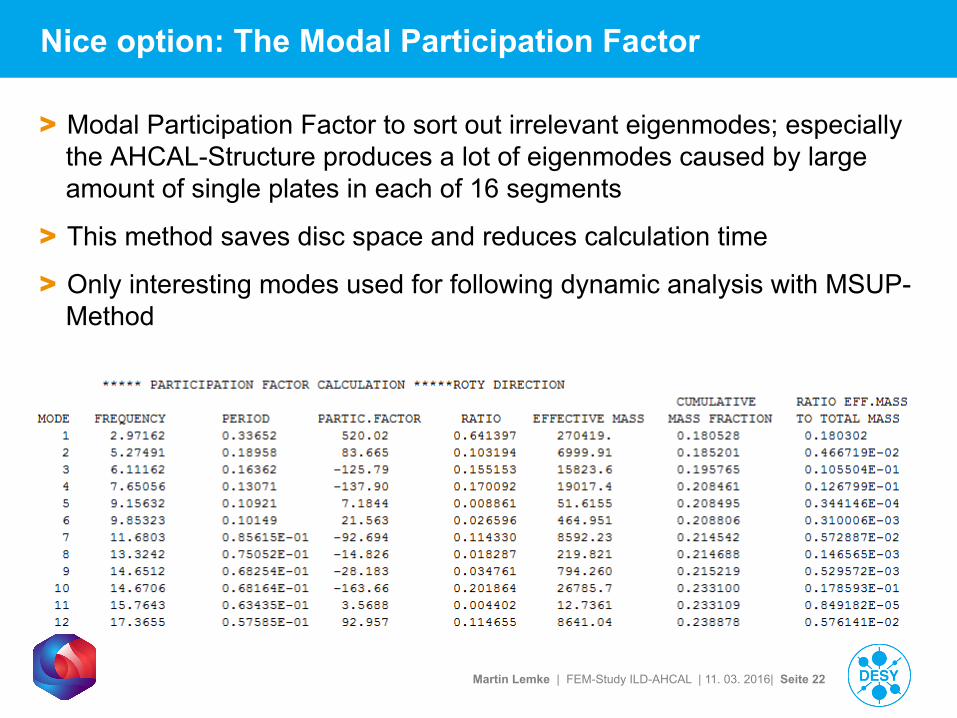
Nice option: The Modal Participation Factor
> Modal Participation Factor to sort out irrelevant eigenmodes; especially the AHCAL-Structure produces a lot of eigenmodes caused by large amount of single plates in each of 16 segments
> This method saves disc space and reduces calculation time
> Only interesting modes used for following dynamic analysis with MSUP-Method
Martin Lemke | FEM-Study ILD-AHCAL | 11. 03. 2016| Seite 23
To Do: General tasks (short term schedule)
> Build up the pre-stressed modal analysis with CMS-Testmodel (actually working)
> Response spectrum analyses with earthquake data generalised with ISO 3010 and Eurocode 8
> Handover the modal-results to a response spectrum analysis with Earthquake data from Japan/Ichinoseki (Source:NIED K-NET IWT010 2011/03/11) has to be implemented in the Testmodel, max. amplitudes: § East-West 852,134 gal (alternatively 8,52 m/sec² => 0,36 g)
§ North-South: 997,780 gal (alternatively 9,98 m/sec² => 1,02 g)
§ Vertical: 352,666 gal (alternatively 3,53 m/sec² => 0,36 g)
> Mandatory: regular adjustments in models (Commands, geometry, …)
Martin Lemke | FEM-Study ILD-AHCAL | 11. 03. 2016| Seite 24
Response Spectrum Analysis
> In DIN 3010, the Response Spectrum Analysis ist recommended for earthquake analysis on structures
> In ANSYS the Response Spectrum Analysis uses the excitation power spectrum to calculate the maximum answer of the structure (max. amplitude) for a specific frequency
> For Response spectrum analysis the SRSS-Method is used (SRSS => Square root of sum of squares)
> Mass- and stiffness damping (both 0,01) are used to calculate real/finite amplitudes for the structure
> The frequency at the max. Amplitude in Response Spectrum Analysis con be used to set up a Transient Analysis to investigate time-dependent behavior of the structure
Martin Lemke | FEM-Study ILD-AHCAL | 11. 03. 2016| Seite 25
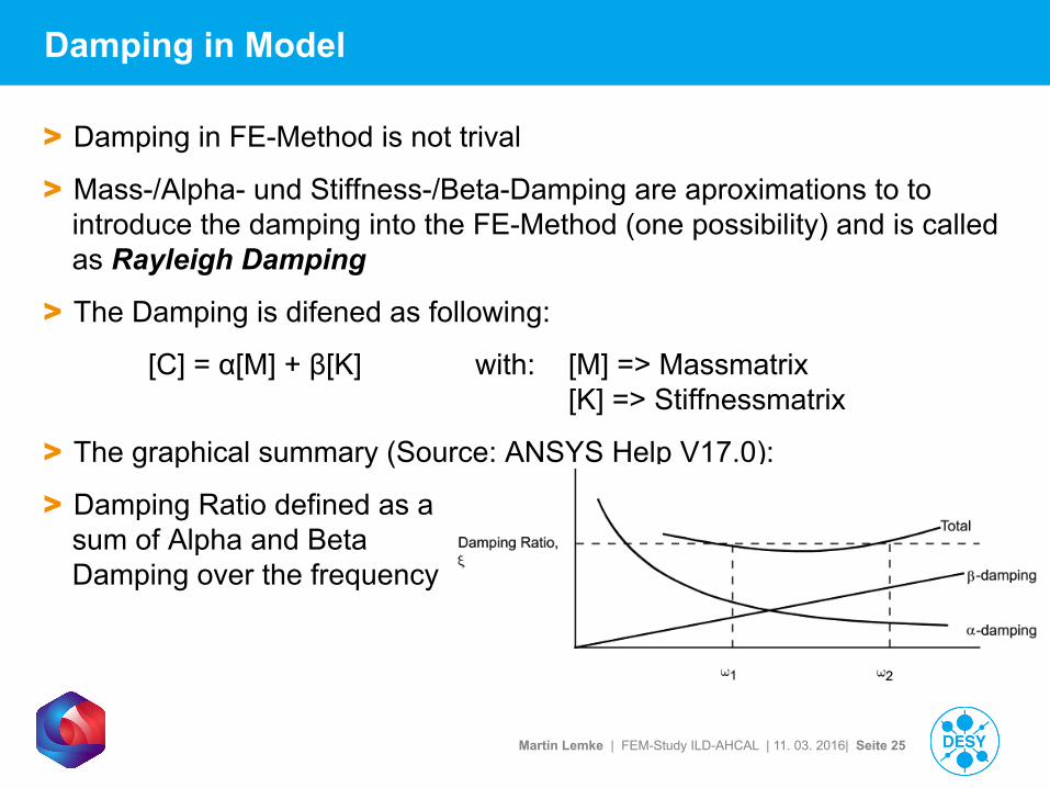
Damping in Model
> Damping in FE-Method is not trival
> Mass-/Alpha- und Stiffness-/Beta-Damping are aproximations to to introduce the damping into the FE-Method (one possibility) and is called as Rayleigh Damping
> The Damping is difened as following:
[C] = α[M] + β[K] with: [M] => Massmatrix [K] => Stiffnessmatrix
> The graphical summary (Source: ANSYS Help V17.0):
> Damping Ratio defined as a sum of Alpha and Beta Damping over the frequency
Martin Lemke | FEM-Study ILD-AHCAL | 11. 03. 2016| Seite 26
Pre-stressed Testmodel with CMS-Method
> Setup a pre-stressed, damped Modal Analysis
> Test setup (simple ring of eight segments) used to develop ANSYS program scripts for data transfer from Static Structural Analysis to Modal Analysis afterwards to Response Spectrum Analysis
> In the Static Structural Run the load dependent structure deformations are calculated
> The Modal Analysis in ANSYS uses the linear Perturbation Method to calculate the initial deformations of the structure
> Successfully tested and adaption to the AHCAL-FE-Model
> To reduce the complexity of the AHCAL-FE-Model, only the AHCAL-Structure is used in the analysis without barrel, cryostat, …
> Actually the pre-stressed AHCAL-Model is in calculation since one day
Martin Lemke | FEM-Study ILD-AHCAL | 11. 03. 2016| Seite 27
Conclusions for prestressed AHCAL-Model with CMS-Method
> Difficult to debug the complete AHCAL-FE-Model-Setup
> Actually the scripts and the model works well
> The actual model size is about 1.5 Mio Nodes
> 95 GB RAM are used by the Block anzos Modal Solver in ANSYS
> Temporary Solver files have a size around 400 GB!!!
> The solution is very slow caused by a lot I/O (data file handling) within the solve process (=> different FEM-Server-Setup needed to optimize the solution-process?!)
Martin Lemke | FEM-Study ILD-AHCAL | 11. 03. 2016| Seite 28
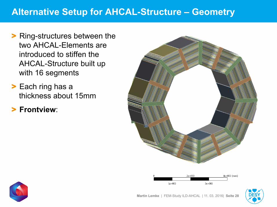
Alternative Setup for AHCAL-Structure – Geometry
> Ring-structures between the two AHCAL-Elements are introduced to stiffen the AHCAL-Structure built up with 16 segments
> Each ring has a thickness about 15mm
> Frontview:
Martin Lemke | FEM-Study ILD-AHCAL | 11. 03. 2016| Seite 29
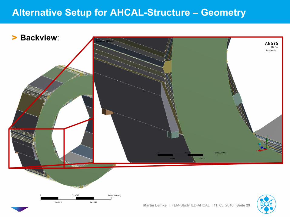
Alternative Setup for AHCAL-Structure – Geometry
> Backview:
Martin Lemke | FEM-Study ILD-AHCAL | 11. 03. 2016| Seite 30
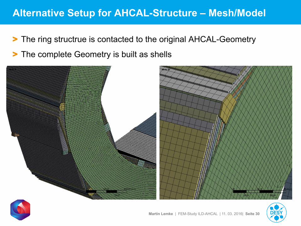
Alternative Setup for AHCAL-Structure – Mesh/Model
> The ring structrue is contacted to the original AHCAL-Geometry
> The complete Geometry is built as shells
Martin Lemke | FEM-Study ILD-AHCAL | 11. 03. 2016| Seite 31
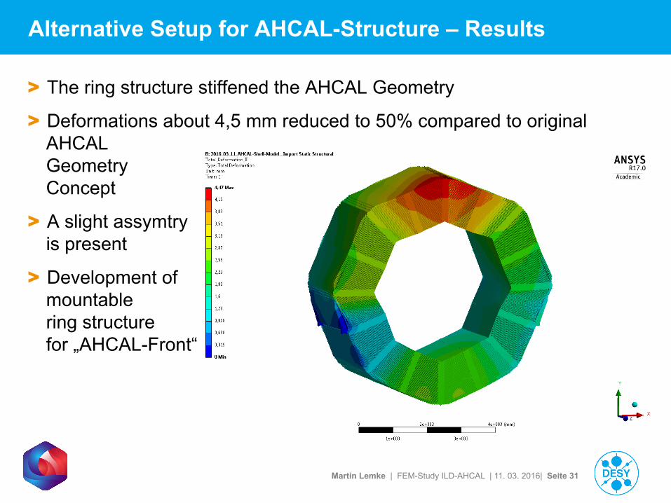
> The ring structure stiffened the AHCAL Geometry
> Deformations about 4,5 mm reduced to 50% compared to original AHCAL Geometry Concept
> A slight assymtry is present
> Development of mountable ring structure for „AHCAL-Front“
Alternative Setup for AHCAL-Structure – Results
Martin Lemke | FEM-Study ILD-AHCAL | 11. 03. 2016| Seite 32
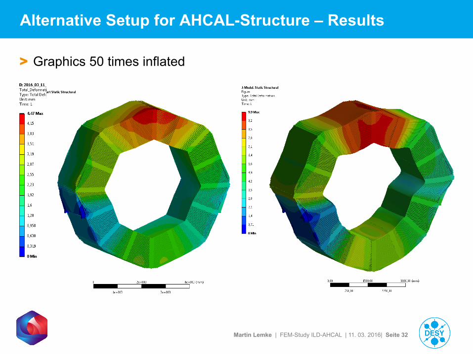
Alternative Setup for AHCAL-Structure – Results
> Graphics 50 times inflated
Martin Lemke | FEM-Study ILD-AHCAL | 11. 03. 2016| Seite 33
Summary, outlook and remarks
> Seismic study is progressing
> Successful change to sub-structure method which will ultimately allow integration into cryostat and yoke whilst retaining all details
> Getting ready to simulate with real earthquake data
> However, do far each new step brought new challenges…
> Will also address rotated case (by 22o as preferred by ECAL) and ECAL support details
> Results are conservative with respect to § Thicker absorber (fewer layers for cost resuction)
§ Smaller inner radius
§ Adaption to SiD
Martin Lemke | FEM-Study ILD-AHCAL | 11. 03. 2016| Seite 34
Glossar
> APDL => ANSYS Parametric Design Language (ANSYS scripting/programming language to expand the capabilities in ANSYS Workbench)
> Master DOF => a previously defined set of nodes, which are excluded from substitution with the superelement and to define boundary conditions and contacts to other bodies/parts/superelements
> CMS => Componenent Mode Synthesis
> MSUP => Modal Superposition Method
> Modal Participation Factor => Each mode of a structure has an effective mass representing the share in the relevance for structural dynamic investigations, for this reason a modal participation factor less then a defined value will have no relevant impact on following dynamic analsis reusing the modal results for the MSUP-Method