Embed Size (px)
Citation preview

FEM MODEL FOR VHV MACHINE
FEM model for a VHV machine Thesis for the Degree of Master of Science
XI YANG
Department of Energy and Environment Division of Electric Power Engineering CHALMERS UNIVERSITY OF TECHNOLOGY Göteborg, Sweden, 2008

1
2
FEM model for VHV machine Master’s Thesis in Electrical Power Engineering
Xi Yang
Examiner: Dr. Sonja Tidblad Lundmark, CTH
Supervisor: Dr. Yujing Liu, ABB Corporate Research
Department of Energy and Environment
Division of Electric Power Engineering
CHALMERS UNIVERSITY OF TECHNOLOGY
Göteborg, Sweden, 2008

3

4
ACKNOWLEDGEMENTS First of all, I would like to thank to Chalmers University of Technology and ABB Corporate research for providing me with such a wonderful opportunity to study and work in this excellent project.
Secondly, I would like to thank to my supervisor: Dr. Yujing Liu at ABB Corporate Research for giving me access to all necessary means and support in this project and for his brilliant ideas, guidance and inspiration. For the thesis period in ABB, I would also like to thank to Dr. Pär Ingelström, who give me support not only in using new programs but also analysis ways full of intelligence. For their effort and helpful comments, I would like to thank to Dr. Heinz Lendenmann and Dr. Marguerite Holmberg.
I’m deeply grateful to my dear Examiner: Dr. Sonja Tidblad Lundmark in Chalmers University of Technology, for her technology support and valuable knowledge during both the period when I was studying in Chalmers University of Technology and doing the thesis work in ABB.
I would like to thank to all of staff and classmates at the department for their teaching and assistance during this period.
Last but not least, I must thank my parents who always give me all their love and support and my friends who always helped and encouraged me during this period.

5

6
ABSTRACT The cable wound VHV (Very High Voltage) synchronous machine is a new machine type directly driven by a HVDC-Light inverter and is used on oil platforms. However, in order to find more cost-effective designs, a design tool is necessary.
In this thesis work, a FEM model for cable synchronous machines is developed. Python language has been used to model and mesh the geometry under the Flux2D FEM environment. Delphi is used to control the simulation flow. The thesis work includes software design, coding and debugging according to requirements. The model has been tested on a typical design of a cable synchronous machine designed by ABB Machines, Västerås.
Additionally, the model has been integrated in the ABB simulation program, SynFEM, which is a FEM platform for different analysis, such as magnetostatics, time-stepping, and thermal calculations, for synchronous machines. This integration made it easier and more efficient to use the VHV model in the designer's environment.
To achieve the above, the accumulated knowledge on different computer languages, simulation platforms, and machines is required. To build this model which has a more complicated stator geometry compared to conventional stators is also time-consuming.
This report includes the main files of the VHV machine model and some simulation results of both magnetostatics and time-stepping simulations.
Key words: VHV machine, SynFEM, simulation.

7

8
TABLE OF CONTENTS FEM model for VHV machine................................................................................................... 0 Acknowledgements .................................................................................................................... 4 Abstract ...................................................................................................................................... 6 Table of Contents ....................................................................................................................... 8 Nomenclature ............................................................................................................................. 9 1 Introduction .......................................................................................................................... 10
1.1 Purpose ........................................................................................................................... 10 1.2 Scope .............................................................................................................................. 10 1.3 Structure ......................................................................................................................... 10
2 Synchronous machines and VHV machine applications....................................................... 11 2.1 Machine background ...................................................................................................... 11 2.1.1 Basic knowledge of electrical machines................................................................................................... 11 2.1.2 EMF in slots of machine .......................................................................................................................... 11 2.2 Machine construction ..................................................................................................... 12 2.2.1 Stator construction ................................................................................................................................... 12 2.2.2 The rotor construction .............................................................................................................................. 12 2.2.3 Cooling system......................................................................................................................................... 14 2.3 VHV machine................................................................................................................. 15 2.3.1 Benefits of VHV machine systems .......................................................................................................... 15 2.3.2 Special design of VHV machine .............................................................................................................. 16 2.3.3 Applications ............................................................................................................................................. 17
3 VHV FE model and implementation..................................................................................... 19 3.1 Descriptions of SynFEM................................................................................................ 19 3.2 Programs and computer languages................................................................................. 22 3.2.1 Overview of SynFEM interface and abilities ........................................................................................... 22 3.2.3 Delphi files ............................................................................................................................................... 28 3. 3 VHV machine parameters ............................................................................................. 29 3.4 Physical, material and meshing...................................................................................... 32 3.4.1 Stator_defcable.py.................................................................................................................................... 32 3.4.2 SSLOTcable.py ........................................................................................................................................ 32 3.4.3 Alloc1cable.py ......................................................................................................................................... 36 3.4.4 Stator_corecable.py.................................................................................................................................. 37 3.4.5 Rotor part ................................................................................................................................................. 38
4. Simulation results and analysis ............................................................................................ 40 4.1 Machine data .................................................................................................................. 40 4.2 Magnetostatics................................................................................................................ 40 4.2.1 No-load..................................................................................................................................................... 40 4.2.2 Load point ................................................................................................................................................ 43 4.3 Time Stepping ................................................................................................................ 44 4.3.1 No-load simulation................................................................................................................................... 44 4.3.2 Current-source load simulation ................................................................................................................ 47 4.3.3 2-phase short circuit ................................................................................................................................. 51 4.4 Analysis of air gap length............................................................................................... 56
5 Conclusions .......................................................................................................................... 58 6 Future Work ......................................................................................................................... 58 References ................................................................................................................................ 59
Technical papers and reports................................................................................................ 59 Website................................................................................................................................. 59

9
NOMENCLATURE
ε Induced voltage (V)
fI Rotor current (A)
BΦ Magnetic flux (T)
inP Input power (kW)
outP Output power (kW)
η Efficiency
Wk Winding factor
p Number of pole pairs
Sω Synchronous speed (rad/s)
Ω Angle speed (rad/s)
MMF Magneto Motive Force
EMF Electro Motive Force
B Flux density (Tesla)
SQ Number of stator slots
FEM Finite Element method
nS Apparent power (kW)
nU Rated voltage (V)
nI Rated current (A)
f Frequency (Hz)
1oD Stator outer diameter (mm)
T Magnetic torque (kNm)
N Number of coil turns
J Moment of inertia (kg 2m )

10
1 INTRODUCTION
1.1 Purpose The purpose of the work described in this report is to build a finite element model for VHV (Very High Voltage) synchronous machines with a cable wound stator and to give simulation results and analysis.
1.2 Scope This report focuses on the new design of VHV synchronous machine model in the program SynFEM. Firstly, it doesn’t attempt to describe the entire code in detail, but tried to give a good introduction and overview of the programs and files which are used, so that a reader can easily find the main idea of the new part in SynFEM. Secondly, some details of the geometry and mesh design are described and shown in pictures to make a clear understanding. Last but not least, some results of the simulations done in this new SynFEM version are presented.
The high voltage cable windings in VHV machines provide the possibility to be directly connected to a high voltage power network without a step-down transformer. One typical application is as compressors on oil platforms. The machines can be driven directly by a HVDC-Light inverter. Although the whole system of SynFEM is not a new program, the VHV synchronous machine part is completely new because the special voltage needs special stator slot shapes and special windings (HV-cable). Compared with the conventional machines in SynFEM, the new model is much more complicated in geometry and time-consuming in running.
1.3 Structure This report has the following structure:
Section 1 Introduction (this section) describes the purpose, scope for this report and overview of the VHV synchronous machine.
Section 2 gives a general background to machines (synchronous VHV machines) and their applications.
Section 3 describes the VHV FE model and its implementation. To build the SynFEM, the program Delphi, Flux, and Python languages are used.
Section 4 presents the simulation results of VHV machines by using SynFEM. They include both magnetostatics and time-stepping analysis. For the magnetostatic condition, the no-load and load points are considered while in the time-stepping condition, we can do the analysis of:
1) Steady state, current source in the stator,
2) No-load
3) A 2-phase short-circuit in the simulation of this special machine.
Section 5 and 6 give conclusions of the project and a plan of future work in some relevant aspects.

11
2 SYNCHRONOUS MACHINES AND VHV MACHINE APPLICATIONS
2.1 Machine background
2.1.1 Basic knowledge of electrical machines
An electrical machine is a device, which converts electrical power into mechanical power when it works as a motor. Power can also be converted in the opposite way, which means that mechanical power is converted into electrical power. Under these circumstances the electrical machine works as a generator.
Or we can say
Generator: Electrical power=Mechanical power-Losses
Motor: Mechanical power= Electrical power-Losses
Because of losses in the machine: mechanical losses (due to mechanical friction and windage), copper losses (which is also called I2R losses that can be found in all windings like armature windings and field windings) and core losses (hysteresis losses and eddy current losses), we can calculate the efficiency as the ratio between output power Pout and input power Pin:
in
outP
P=η (2.1)
2.1.2 EMF in slots of machine
According to basic knowledge of electrical machines, the magnetic fields from dc currents in the rotor windings will generate an electromagnetic force (EMF) in the stator windings when the rotor is rotating at a speed π2 f. The phase voltage at no-load can be expressed as:
0Wrms kNf44.4E Φ××××= (2.2)
where f is the frequency, N is the number of turns in the stator phase winding, Wk is
the winding factor, and 0Φ is the maximum value of the linked flux.

12
2.2 Machine construction
2.2.1 Stator construction
Fig 2.2.1 ABB stator in a salient pole machine [7]
For the VHV machine, the stator winding is different from the conventional machines. A conventional stator is shown in Fig. 2.2.1. The concept of VHV machine is based on using cable windings, instead of the traditional stator windings with rectangular conductors, based on proven high-voltage cable technology with solid dielectric. This will be further discussed in Section 2.3.2.
2.2.2 The rotor construction
There are two main types of rotor constructions of synchronous machines: one is the cylinder-rotor while the other type is the salient-pole rotor, which are described in Fig. 2.2.2 below. The cylindrical rotor construction can be used for 2- and 4-pole turbine generators for instance. The salient-pole machine can be used for multipolar, slow-speed hydro generators and synchronous motors for example. The number of poles of synchronous motors can be different, although the most common type is the one with four poles as in Fig 2.2.3.

13
Fig. 2.2.2 Rotor types [8]
a) round-rotor b) salient-pole rotor
Fig. 2.2.3 Salient pole rotor (four poles) [8]
Although the stator of the VHV synchronous machine is a definitely new design, the rotor can be chosen from the conventional ones to do the simulation and in real production as well.

14
2.2.3 Cooling system
The internal parts of a salient pole synchronous machine are cooled by forced convection using either an axis mounted fan or external fans. External fans give more flexibility to control the flow rate and in the case of a variable speed machine it is essential to provide cooling at low speeds. Axis mounted fans are however easier and cheaper to manufacture and will also contribute to a higher efficiency.
Machines are either open or closed. In the case of a closed machine, there is normally some kind of heat exchanger on top of the machine. The air that enters the machine is thus circulating in a closed loop from the heat exchanger and back again
[7]. The heat exchanger can be either of water type or air type. The ventilation arrangement of a closed machine with heat exchanger is shown in Fig.2.2.4.
As described in Johan Ohlsson’s report [7], the importance of efficient cooling of electrical machines can not be underestimated. The power which can be taken out of a given electrical motor is primarily limited by the allowable temperature in the windings. Moreover, excessive temperatures radically shorten the lifetime of the insulation material.
It has been noticed that the lifetime of the insulation is closely related to the occurrence of so-called hot spots in the winding [4]. The hot spots may arise from stationary or re-circulating air. This is due to the fact that the heat taken away from the windings by convection is strongly dependent on the velocity of the flow. The location of hot-spots in synchronous machines is found behind the coil supports and at the inlet of the stator radial ducts – areas where turbulent air is assumed to create re-circulation. There is also a tendency that the rotor may be warmer towards the middle of the machine, due to the fact that the flow rate decreases along the rotor. The VHV stator is cooled by circulating water in plastic pipes along the cables in order to control the temperature.
Fig. 2.2.4 Ventilation arrangement for a closed machine with symmetrical ventilation [7]

15
2.3 VHV machine
2.3.1 Benefits of VHV machine systems
The benefits of a VHV machine system is summarized below compared with a conventional machine system (see Figs. 2.3.1 and 2.3.2). It is seen that when comparing with a conventional system, the high voltage cable winding motors (VHV machines) can be directly connected to the high voltage power network without costly step-down transformers.
Fig 2.3.1 a) Conventional machine system b) VHV machine-based station
Fig 2.3.2 Use of VHV machine eliminates transformer losses (A). Only motor losses (B) remain [1].
16
According to reference[1] the VHV machine also reduces the total system losses by as much as 25% (see Fig 2.3.2). Being epoxy-free, it also has important environmental benefits, including being easy to recycle. Further, fewer components mean higher system reliability and availability, plus reduced costs for service, maintenance and spares.
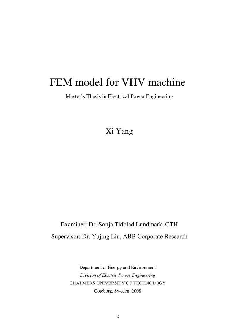
2.3.2 Special design of VHV machine
The special design of a stator cable winding as well as the housing of a VHV machine is shown in Fig. 2.3.3. The VHV machine uses a conventional rotor in combination with the new stator design.
(a) (b)
Fig 2.3.3 The stator cable winding of VHV machine (a) and corresponding machine housing (b) Photo: ABB
For VHV machines, the thick insulation layer surrounding the copper core in the cables provides high voltage insulation ability. On the other hand, the cable insulation, which is made from the plastic material PEX, cannot withstand the same temperature as the insulation materials in conventional machines. If the temperature in PEX rises above 90oC, the insulation capacity of PEX is getting worse. The higher the temperature is, the quicker the material ages.
Fig 2.3.4 shows the 3D model of a VHV machine consisting of only one slot and two half teeth. It is impossible to model the whole machine or a pole of the machine due to the enormous problem size.
According to a reference paper [2], the criterion of temperature in the cables for design practice is limited to C70° . If the ambient temperature is set to C30° , the temperature rise in the stator due to all the losses is not allowed to be higher than C40° . However, in conventional motors, the stator temperature rise can in principle be as high as C120° . It is thus obvious that the limitation of temperature in a VHV motor is extremely strict.

17
Fig 2.3.4 3D model of cable windings in a stator slot, detail of cables [1]
In order to reduce the temperature in the stator core, a water-cooling system is applied in the stator core. The heat from the eddy losses in the cables (stator winding) is transferred through the stator core to the cooling water through the thick PEX insulation.
In the electrical design of the machine, the temperature calculations are mainly made based on the common iron losses in the stator since the core end iron losses usually are quite small compared with the main iron losses.
2.3.3 Applications
As it is a relatively new invention, the applications of the VHV machine are becoming wider and wider. The first VHV machine to go into commercial operation, at the AGA plant in Sweden, has verified the many benefits of using HV cable technology in large electric motors. Cable machines are suitable for many applications where conventional technology is used today.
The first product to be based on this principle was an HV cable-wound generator. Shortly afterwards, the same concept was applied to motors, resulting in the development of a synchronous machine, named ‘VHV machine’. The first unit was installed in 2001 at an air separation plant in Sweden, where it drives a compressor. This motor is directly connected to a 42-kV bus.
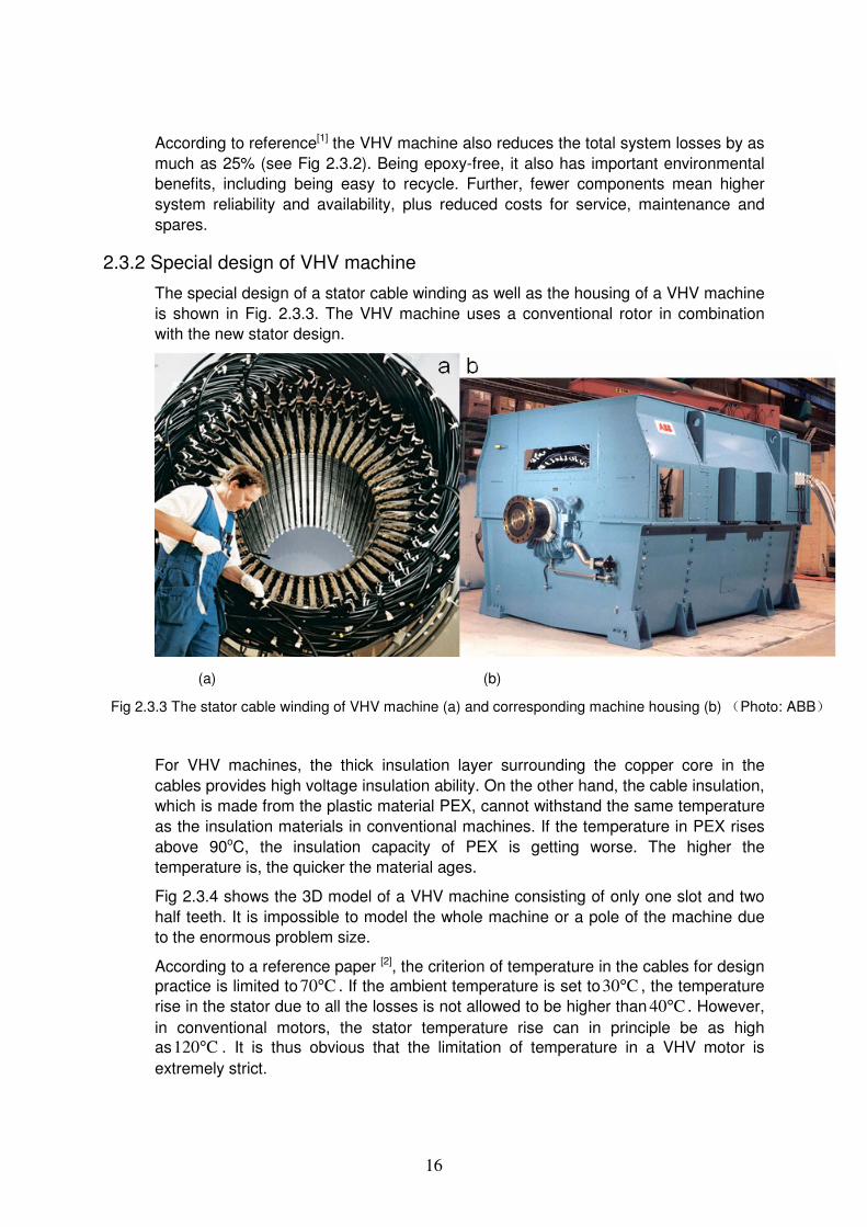
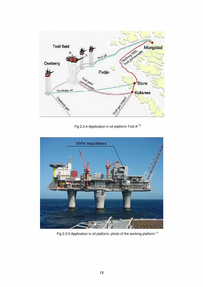
Now, as described in reference paper[1], new technologies are making it easier than ever before to deliver electrical power to offshore installations, lowering operating costs and reducing environmental impact at the same time. 70 kilometres off the Norwegian coast, two of these technologies-HVDC LightTM and VHV machines are helping to power 40-MW compressor units on an oil-platform without any local generation of power, as shown in Fig 2.3.4 and 2.3.5. There, two VHV machines are connected to the HVDC power transmission line with a converter connected in between. The VHV machines are cable wound and are working at a rated voltage of 56kV and at a power of 2x40MW.
18
Fig 2.3.4 Application in oil platform-Troll A [1]
Fig 2.3.5 Application in oil platform, photo of the working platform [1]
19
3 VHV FE MODEL AND IMPLEMENTATION
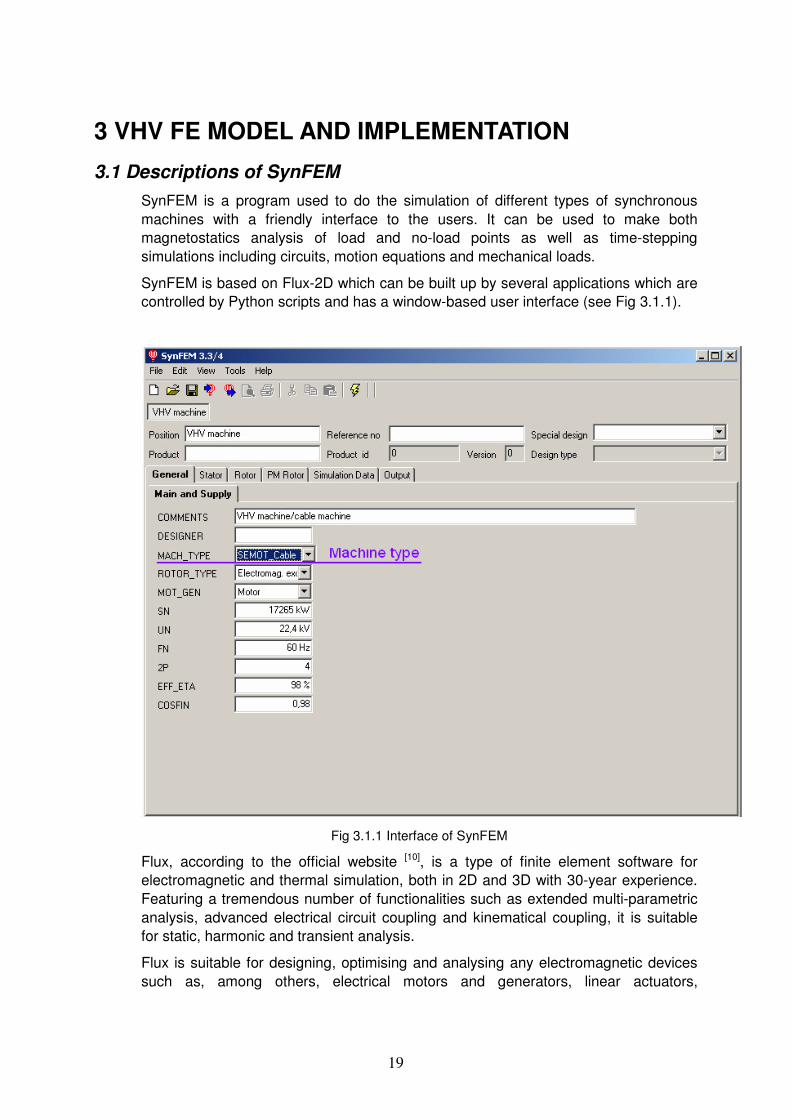
3.1 Descriptions of SynFEM SynFEM is a program used to do the simulation of different types of synchronous machines with a friendly interface to the users. It can be used to make both magnetostatics analysis of load and no-load points as well as time-stepping simulations including circuits, motion equations and mechanical loads.
SynFEM is based on Flux-2D which can be built up by several applications which are controlled by Python scripts and has a window-based user interface (see Fig 3.1.1).
Fig 3.1.1 Interface of SynFEM
Flux, according to the official website [10], is a type of finite element software for electromagnetic and thermal simulation, both in 2D and 3D with 30-year experience. Featuring a tremendous number of functionalities such as extended multi-parametric analysis, advanced electrical circuit coupling and kinematical coupling, it is suitable for static, harmonic and transient analysis.
Flux is suitable for designing, optimising and analysing any electromagnetic devices such as, among others, electrical motors and generators, linear actuators,
20
transformers, induction heating devices, sensors, HV devices, cables, electromagnetic compatibility and non destructive evaluation devices.
Python code (or PyFlux code) is used not only to draw the geometry and mesh generation but also set the conditions of each boundary with Preflu2D.There are two types of python files. One is the run-time file in which different parameters can be defined while the other is the predefined file where the centre parts of the machine such as the stator and rotor has been defined.
Delphi is used to build the library file named SynFEM.dll which can not only select and call the relevant python files in a set sequence for Flux, but also build up the simulation by applications that control the different steps from pre-processing to post-processing.
According to reference paper [1], the overview of flow and design programs can be described as shown in Fig 3.1.2. The procedures in SynFEM.dll (green) generate script files and data files (blue) that are used as input for FLUX. The different FLUX programs (red) are always called through the SynFEM.dll procedure Execute Command (not included in the picture). Which programs to call, and which input files to use, are defined in the run-time generated batch scripts init.bat or init1.bat (lavender), which also sets some environment variables. Depending on the application, the output files from FLUX (yellow) may be read or modified to perform certain analysis.

21
Fig.3.1.2 Overview of flow diagram and design program

22
3.2 Programs and computer languages
3.2.1 Overview of SynFEM interface and abilities
As shown in Fig 3.2.1, the FE models of machines are parameterized with machine data. The model of each part of a machine can be set and modified by filling the blanks with values in the interface (see Figs 3.2.2 - 3.2.4). In the interface (Fig 3.2.2), those parameters which are blocked (with colour grey) are not used for cable machines since now it is under cable machine mode (see Fig 3.1.1, machine type). However, these parameters will be available for conventional machines. The rotor part interface is shown in Fig 3.2.3. As seen here not only the parameter values but also the materials and the field windings of the rotor can be set and modified here.
Fig 3.2.1 Detail of stator (cable machine) interface in SynFEM
23
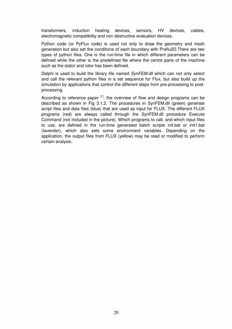
Fig 3.2.2 Detail of stator (both conventional and cable machine) interface in SynFEM
Fig 3.2.3 Detail of rotor (conventional machine) interface in SynFEM
24
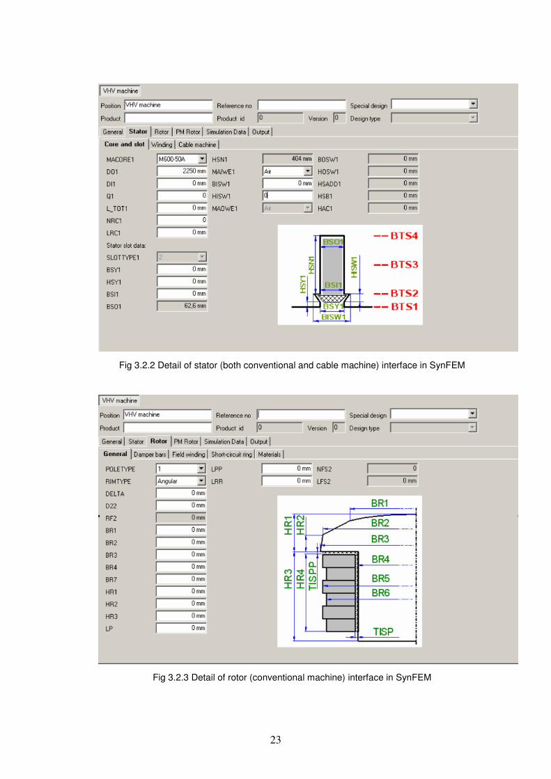
Fig 3.2.4 Detail of stator (PM rotor) interface in SynFEM
.
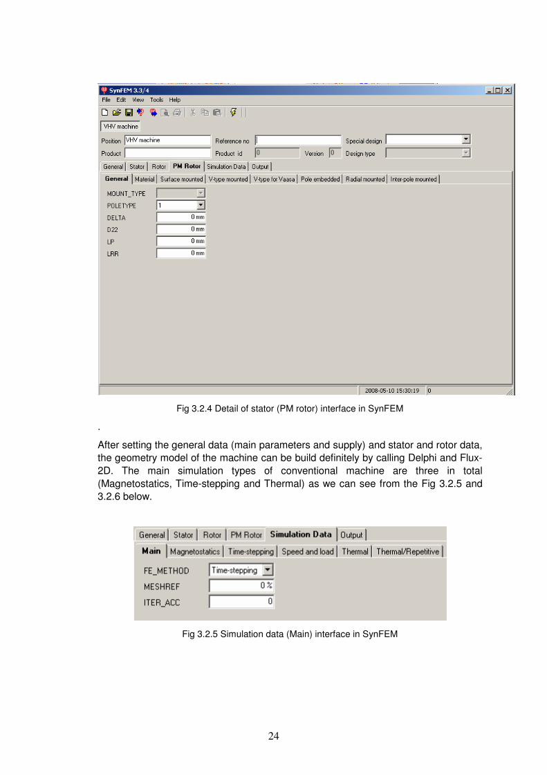
After setting the general data (main parameters and supply) and stator and rotor data, the geometry model of the machine can be build definitely by calling Delphi and Flux-2D. The main simulation types of conventional machine are three in total (Magnetostatics, Time-stepping and Thermal) as we can see from the Fig 3.2.5 and 3.2.6 below.
Fig 3.2.5 Simulation data (Main) interface in SynFEM
25
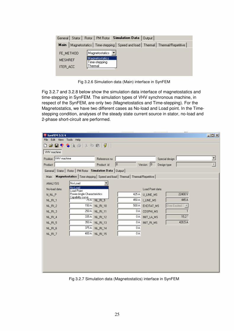
Fig 3.2.6 Simulation data (Main) interface in SynFEM
Fig 3.2.7 and 3.2.8 below show the simulation data interface of magnetostatics and time-stepping in SynFEM. The simulation types of VHV synchronous machine, in respect of the SynFEM, are only two (Magnetostatics and Time-stepping). For the Magnetostatics, we have two different cases as No-load and Load point. In the Time-stepping condition, analyses of the steady state current source in stator, no-load and 2-phase short-circuit are performed.
Fig 3.2.7 Simulation data (Magnetostatics) interface in SynFEM

26
Fig 3.2.8 Simulation data (Time-stepping) interface in SynFEM
The simulation cases for VHV synchronous machine can be summarized as follows.
Simulation cases:
Magnetostatics:
• No-load: to calculate the no-load voltage in the stator from the rotor.
• Load point: first to find the voltage U and stator current I from the initial load angle INIT_LA_MS, rotor current Rt.Current_MS and the initial power factor COSPHI_MS. Once the results are not the same as given values, system will automatically set other load angle and rI to calculate until the correct point is found. Or we can say until resultrated UU = , resultrated II = .
Time-stepping:
• Current source: sinusoidal current sources are applied in the circuit in each phase. A certain amount of currents are forced to flow through the stator. The terminal voltage is floating.
• No-load: stator windings are open. The rotor runs at a constant speed. No-load voltage and cogging torque can be calculated with different rotor positions.
• 2-phase short circuit: two-phase short-circuit from no-load operation. With a zero value of the inertia, JLOAD, a constant speed 2-phase short circuit case can be simulated.

27
3.2.2 Flux and Python code
The list of python files is shown in table 3.1 below.
Table 3.1 Python files
PyFlux file Created Comment F3d_ini.py Run-time Main file used to call the others Update.py Run-time Defines parameter values to build
geometry Functions.py Pre-defined Contains short form functions *Setnewp.py Pre-defined Set the new parameters which cannot
be found in the basic SynFEM programme Synbasic.flu due to the new type geometry of VHV machine.
Main files
Version.py
Pre-defined Defines a string with the correct version of Flux
*Stator_defcable.py
Pre-defined Prepares the drawing of the stator geometry. Modifies the stator mesh points and lines.
*SSLOTcable.py
Pre-defined Draws the stator slot of the cable machine
*Alloc1cable.py Pre-defined Set the three-phase condition
Stator part
*Stator_corecable.py
Pre-defined Draws the remaining part of the stator
Modifyrtmesh.py Run-time Modifies some rotor mesh points Dampbar.py Pre-defined Defines the central part of the pole
surface and its damper bars Rtgeom.py
Pre-defined Draws the rotor poles for conventional machines
Rotor Part
Core.py Pre-defined Creates the air gap (connect stator and rotor)
* Setnewp.py is a special file only used for the VHV machine model.
* Alloc1cable.py - Although the conventional files can be written by Delphi, the file for the cable version has to be written in advance because of the complicated situation. In the future, there could be a table for different winding conditions. Then the suitable case can be called by F3d_ini.py to match more VHV machine versions.
*Stator_defcable.py, *SSLOTcable.py, *Alloc1cable.py and *Stator_corecable.py - All of the special python files for VHV machines are named with ‘cable’ to tell the difference as compared with others except Setnewp.py which is completely new.
28
3.2.3 Delphi files
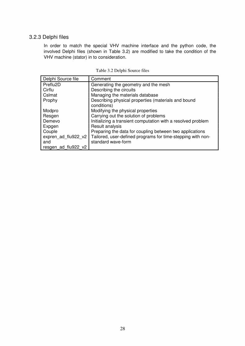
In order to match the special VHV machine interface and the python code, the involved Delphi files (shown in Table 3.2) are modified to take the condition of the VHV machine (stator) in to consideration.
Table 3.2 Delphi Source files
Delphi Source file Comment Preflu2D Generating the geometry and the mesh Cirflu Describing the circuits Cslmat Managing the materials database Prophy Describing physical properties (materials and bound
conditions) Modpro Modifying the physical properties Resgen Carrying out the solution of problems Demevo Initializing a transient computation with a resolved problem Expgen Result analysis Couple Preparing the data for coupling between two applications expren_ad_flu922_v2 and resgen_ad_flu922_v2
Tailored, user-defined programs for time-stepping with non-standard wave-form

29
3. 3 VHV machine parameters The new design of the interface for the VHV machine is shown in Table 3.3 below. The dimensional parameters are also illustrated in Figs 3.3.1 and 3.3.2.
Table 3.3 Parameter list for the stator of the VHV synchronous machine
1) Cable data
Parameter name Unit Comment CONNECT1 Connection (Star or Delta) MACU1 Copper material NUM_CABLE Number of cables in each slot DCOND mm Diameter of cable conductor H_BW_CABLE mm Height between cables centres H_CABLE1 mm Height from inner surface of stator to 1st cable centre H_CABLE2 mm Height from inner surface of stator to 2nd cable centre B_CABLE_MIDSLOT mm Width between the cable centre and the middle line of
slot LM1 mm Half length of a coil R_TEMP °C Temperature of stator resistance XSLE(%) % Stator end-winding reactance (in %)
2) Slot data
Parameter name Unit Comment BSY1 mm Width of stator slot opening HSY1 mm Height of stator slot opening BSI1 mm Width of stator slot (airgap-side) BSY1_MIDSLOT mm Width between the middle of slot and the left slot edge BISW1 mm Width of slot wedge HISW1 mm Height of slot wedge BSI1_MIDWEDGE mm Width between the middle of slot and the left slot edge
between the wedge and 1st cable MAIWE1 Material of the slot wedge SLTWANG ° Angle for slot wedge SLTR1 mm Radius of 1st arc on right side SLTR2 mm External radius of cable SLTR3 mm Radius of arc between two cables SLTR4 mm Radius of Arc at slot bottom
3) Bolt data
Parameter name Unit Comment D_BOLT_1 mm Diameter of 1st bolt at the left side of tooth tip D_BOLT_2 mm Diameter of 2nd bolt at the right side of tooth tip R_BOLT_CENTRE_1 mm Radius from the centre of machine to the centre of 1st
bolt R_BOLT_CENTRE_2 mm Radius from the centre of machine to the centre of 2nd
bolt ANG_ BOLT_1 ° Angle to place 1st bolt ANG_ BOLT_2 ° Angle to place 2nd bolt

30
Fig 3.3.1 Interface picture of stator slot

31
Fig 3.3.2 Interface picture of stator slot

32
3.4 Physical, material and meshing Due to a very complicated geometry of the stator, both designing and meshing the stator part are very time-consuming.
To build it, four python files (Stator_defcable.py, SSLOTcable.py, Alloc1cable.py and Stator_corecable.py) with more than 1000 lines in total are built. These files are shortly explained in Table 3.1 and explained more in detail below.
3.4.1 Stator_defcable.py
This file is used to prepare the drawing of the stator geometry. Further, the stator mesh points and lines are defined in this file with 127 lines. Twenty-five middle parameters which can predigest the future calculation in the coming files are set here as well.
3.4.2 SSLOTcable.py
This is the centre part; to draw the main geometry of stator and modify the mesh condition.
The currently used design has twelve cables in each slot. At least 100 reference points have to be calculated to set the location of these cables under the stator slot reference frame called STSLOT. Also, more than 120 points are used per slot for the slot itself, slot teeth and bolts in respect of some other reference frame named SXY1.
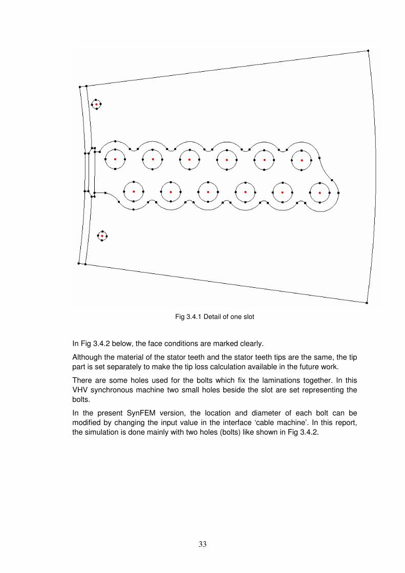
The picture Fig 3.4.1 shows the point setting detail of one slot. The red points are only used to give the coordinates for drawing the arcs but are not drawn in Flux.
33
Fig 3.4.1 Detail of one slot
In Fig 3.4.2 below, the face conditions are marked clearly.
Although the material of the stator teeth and the stator teeth tips are the same, the tip part is set separately to make the tip loss calculation available in the future work.
There are some holes used for the bolts which fix the laminations together. In this VHV synchronous machine two small holes beside the slot are set representing the bolts.
In the present SynFEM version, the location and diameter of each bolt can be modified by changing the input value in the interface ‘cable machine’. In this report, the simulation is done mainly with two holes (bolts) like shown in Fig 3.4.2.

34
Fig 3.4.2 Stator face conditions
The yellow and red circles represent the conductor in the cable. This cable (See Fig 3.4.3), which is used in VHV synchronous machines, is used instead of the conventional windings. As the cable has a very thick insulation layer, the material of the insulation part and some air in the middle of the cables are set together, considered as air (AIR_S).
Fig 3.4.3 Stator cable [3]

35
For setting all six slots in the stator under each rotor pole, five more slots are needed. This is done just by propagate the union of all settings of the first slot and slot teeth for another five unions. In this case, the rotation is defined by angles and pivot point coordinates. The rotation angle is 360/Q1, where Q1 is the number of stator slots and the coordinates of the pivot point is (0, 0) in the definition coordinate system XY1.
After doing the propagation, the stator slots for one pole can be drawn with their face and mesh settings (See Fig 3.4.4 and 3.4.5).
Fig 3.4.4 Stator under one pole
36
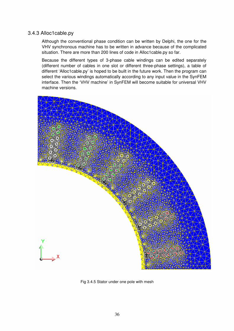
3.4.3 Alloc1cable.py
Although the conventional phase condition can be written by Delphi, the one for the VHV synchronous machine has to be written in advance because of the complicated situation. There are more than 200 lines of code in Alloc1cable.py so far.
Because the different types of 3-phase cable windings can be edited separately (different number of cables in one slot or different three-phase settings), a table of different ‘Alloc1cable.py’ is hoped to be built in the future work. Then the program can select the various windings automatically according to any input value in the SynFEM interface. Then the ‘VHV machine’ in SynFEM will become suitable for universal VHV machine versions.
Fig 3.4.5 Stator under one pole with mesh
37
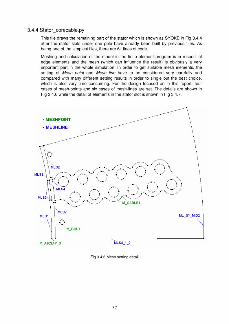
3.4.4 Stator_corecable.py
This file draws the remaining part of the stator which is shown as SYOKE in Fig 3.4.4 after the stator slots under one pole have already been built by previous files. As being one of the simplest files, there are 61 lines of code.
Meshing and calculation of the model in the finite element program is in respect of edge elements and the mesh (which can influence the result) is obviously a very important part in the whole simulation. In order to get suitable mesh elements, the setting of Mesh_point and Mesh_line have to be considered very carefully and compared with many different setting results in order to single out the best choice, which is also very time consuming. For the design focused on in this report, four cases of mesh-points and six cases of mesh-lines are set. The details are shown in Fig 3.4.6 while the detail of elements in the stator slot is shown in Fig 3.4.7.
Fig 3.4.6 Mesh setting detail

38
Fig 3.4.7 Mesh detail
3.4.5 Rotor part
Even though a new stator design is used in this machine, the rotor can be chosen from the conventional ones for any simulation.
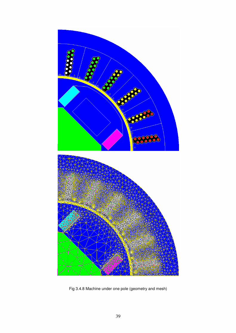
After adding the rotor part, which is a salient-pole in this simulation, the Flux problem will be saved automatically as a PostFlux document named GEOMETRY (following the last sentences in the main file F3d_ini.py). Fig 3.4.8 shows one complete pole-pitch of the machine.
39
Fig 3.4.8 Machine under one pole (geometry and mesh)

40
4. SIMULATION RESULTS AND ANALYSIS
4.1 Machine data
In this chapter, the simulation and result analysis are shown based on a VHV machine with data summarized below.
The investigated machine is a 4-pole 3-phase cable wound motor with a solid pole rotor. The rotor has the same construction as conventional AC machines.
Rated data:
nS = 17.265MVA, nU = 22.4 kV,
nI = 445A, f =60 Hz, ncosϕ = 0.98,
fnI =420.5A, Load angle = 15.2
Dimensions:
1oD = 2250 mm
Parameters:
Number of stator slots = 24
Number of layers of cables = 6
Number of columns of cables = 2
4.2 Magnetostatics
4.2.1 No-load
The magnetostatics interface with input values is shown in Fig 4.2.1. In the no-load case, the program use different input current values (field current) to calculate the related voltage values in the stator and make points according to these results. And then find the point (Interpolated point) which is the closest to the rated voltage value in the curve made by these points. As show in Fig 4.2.1, 10 points are calculated in the no-load case.
Fig 4.2.1 Magnetostatics interface with input values

41
Calculation of no-load voltage is shown in Fig 4.2.2 a).
As can be seen in Fig 4.2.2 a, voltage value of the no-load point at a field current of 337A which is just at the red point Interpolated point in the graph is very close to the given rated voltage value. The voltage at Interpolated point we get is 22402V, which is only with 0.009% difference. This simulation result is almost equal to the given value 22400V.
Fig 4.2.2 a) No-load curve
As the machine should work at the saturation point for the best design, the outer diameter of the stator can be reduced to save material and cost. The current could be increased towards the point of saturation as well. The simulation of the VHV machine with a smaller outer diameter may give a better result. That is what will be included in the future work.

42
The details of the output value can be found in Fig 4.2.2 b) below.
Fig 4.2.2 b) Data of no-load condition
43
4.2.2 Load point
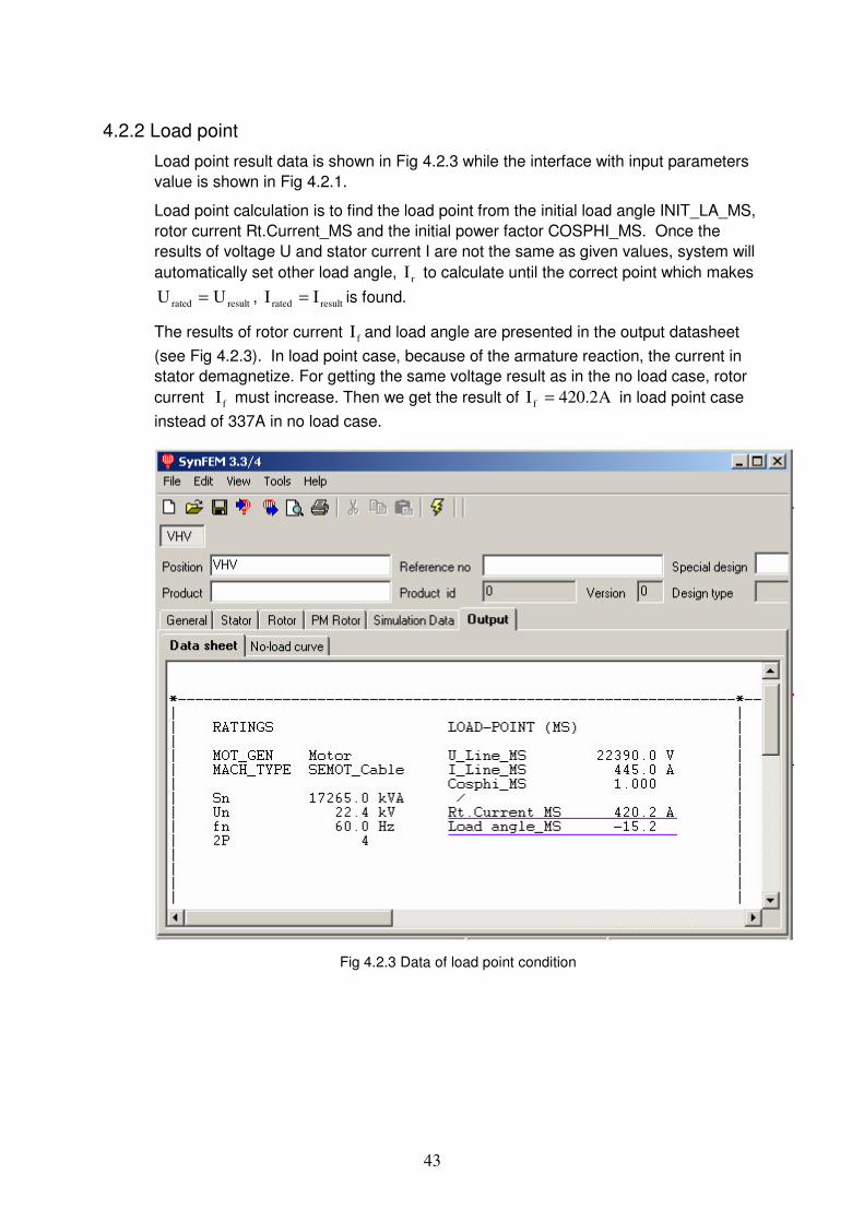
Load point result data is shown in Fig 4.2.3 while the interface with input parameters value is shown in Fig 4.2.1.
Load point calculation is to find the load point from the initial load angle INIT_LA_MS, rotor current Rt.Current_MS and the initial power factor COSPHI_MS. Once the results of voltage U and stator current I are not the same as given values, system will automatically set other load angle, rI to calculate until the correct point which makes
resultrated UU = , resultrated II = is found.
The results of rotor current fI and load angle are presented in the output datasheet (see Fig 4.2.3). In load point case, because of the armature reaction, the current in stator demagnetize. For getting the same voltage result as in the no load case, rotor current fI must increase. Then we get the result of A2.420I f = in load point case instead of 337A in no load case.
Fig 4.2.3 Data of load point condition

44
4.3 Time Stepping In this section, cases of no-load, current source and a 2-phase short circuit are analyzed with time stepping simulations.
4.3.1 No-load simulation
In time-stepping simulations, ‘No load ‘, can be used to check the variations of the induced no-load phase voltage in the stator windings with time and make Fourier analysis.
As in Fig 4.3.1 a) the field winding current in the no-load case simulation is 337A. The simulation result is recorded from the first step with 72 steps in total in two periods.
Fig 4.3.1 a) no-load simulation interface and parameter data
The no-load line voltage (rms) = )kV(86.2243.33p2U3 =××=×× (4 poles),
where )kV(3.3U rms = can be calculated by peak value of voltage shown in Fig4.3.1
b) and also directly show in program. The 3-phase voltage figure can be found below in Fig 4.3.1 b. In the magnetostatics no-load calculation, the voltage is 22400 Volt. It is 2% of difference.

45
Fig 4.3.1 b) 3-phase voltage in two periods (36 steps in each)
As can be seen in the Fourier analysis below and in the picture 4.3.2, the curve is sinusoidal and the influence of harmonics is rare. Treating a 3 phase machine, we get mainly the 5th and 7th harmonics. There are also 11th and 13th harmonics as the teeth harmonics because it has 6 slots in the stator under each rotor pole.
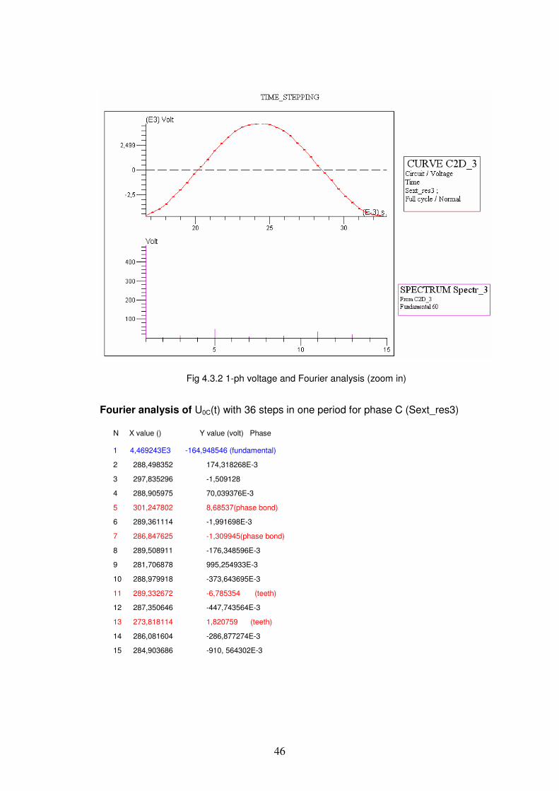
46
Fig 4.3.2 1-ph voltage and Fourier analysis (zoom in)
Fourier analysis of U0C(t) with 36 steps in one period for phase C (Sext_res3)
N X value () Y value (volt) Phase 1 4,469243E3 -164,948546 (fundamental)
2 288,498352 174,318268E-3
3 297,835296 -1,509128
4 288,905975 70,039376E-3
5 301,247802 8,68537(phase bond)
6 289,361114 -1,991698E-3
7 286,847625 -1,309945(phase bond)
8 289,508911 -176,348596E-3
9 281,706878 995,254933E-3
10 288,979918 -373,643695E-3
11 289,332672 -6,785354 (teeth)
12 287,350646 -447,743564E-3
13 273,818114 1,820759 (teeth)
14 286,081604 -286,877274E-3
15 284,903686 -910, 564302E-3

47
4.3.2 Current-source load simulation
The following analysis is for the VHV synchronous machine with a sinusoidal current source while considering a constant rotor speed.
As in Fig 4.3.3 a) the simulation is run by current source with A445I rated = . The circuit
is shown under in Fig 4.3.3 b). Field current is shown as INIT_RI_TS while load angle is shown as INIT_LA_TS in Fig 4.3.3 a).
Fig 4.3.3 a) no-load simulation interface and parameter data
Fig 4.3.3 b) no-load simulation interface and parameter data

48
Magnetic torque
Fig 4.3.4 a) Magnetic torque
Fig 4.3.4 a) shows the Magnetic Torque for the first period (36 steps). As can be seen, the torque is nearly constant but there are still some small ripples caused by the salient-poles. The average magnetic torque in the first period is 22.4 kNm (per pole) (see Fig. 4.3.4 b).
Fig 4.3.3 b) Magnetic torque
Rated torque is )kNm(6.91
2602
265.17
pf2
PPT outout =×=×=
Ω= ππ
So the rated torque under each rotor pole is )kNm(9.2246.91 = . The torque difference between the calculated value and the rated value is then -2.17%.

49
Phase voltage
The phase voltages on this machine for current source are shown in Fig 4.3.4 c).
Fig 4.3.4 c) Phase voltage (under per pole) in current source condition
The voltage (rms) value is 3.31 kV (per pole). Then the calculated line voltage (rms) = )kV(86.223431.3 =×× (4 poles). Compared with the rated voltage (22.4 kV), the
difference is 2.06%. The results from both methods agree well with each other.
Fig 4.3.5 shows the flux density in the stator under one rotor pole. The maximum value is 2.43 Tesla. This is the value when the machine carries rated load. From the Fig 4.3.5, the part with lightest colour means that it is highly saturated. As can be seen, rotor is counter clockwise rotation which give the reason why the left side (to reader) is with higher flux density. And for mathematic reason, too sharp mesh elements can cause higher values in some areas as well. The flux lines under one pole is shown in Fig 4.3.6. We use 50 lines in this picture to describe the field.

50
Fig 4.3.5 Flux density under one rotor pole
Fig 4.3.6 Flux lines of the stator part under one rotor pole

51
4.3.3 2-phase short circuit
By choosing an infinite J load in this condition, we have a constant rotor speed. The analysis is valid for the VHV machine in a 2-phase symmetrical short circuit. The circuit graph of 2-phase short circuit is summarized in Fig 4.3.7. Three-phase resistances S1AR1_1, S1BR1_1, S1CR1_1 are coloured in orange.
Fig 4.3.7 2-phase short circuit
52
Magnetic torque
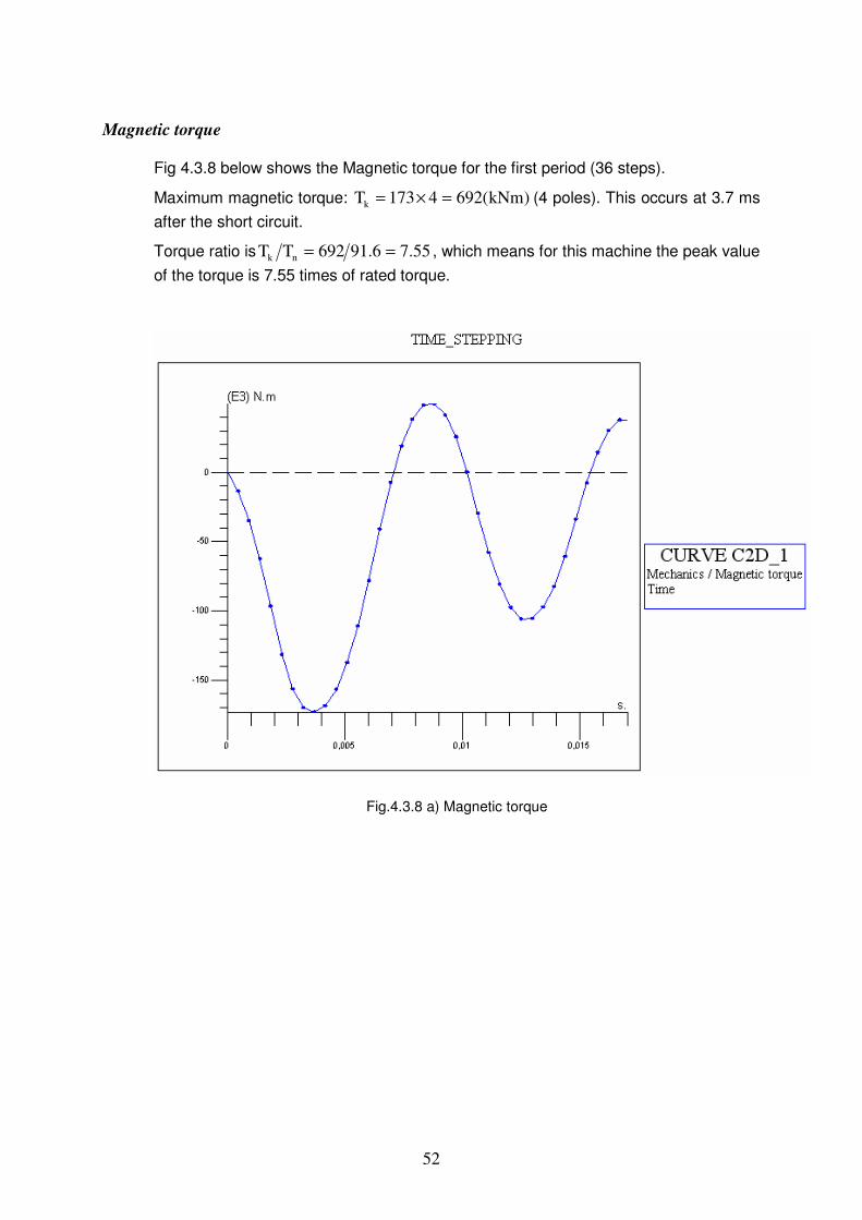
Fig 4.3.8 below shows the Magnetic torque for the first period (36 steps).
Maximum magnetic torque: )kNm(6924173Tk =×= (4 poles). This occurs at 3.7 ms after the short circuit.
Torque ratio is 55.76.91692TT nk == , which means for this machine the peak value of the torque is 7.55 times of rated torque.
Fig.4.3.8 a) Magnetic torque
53
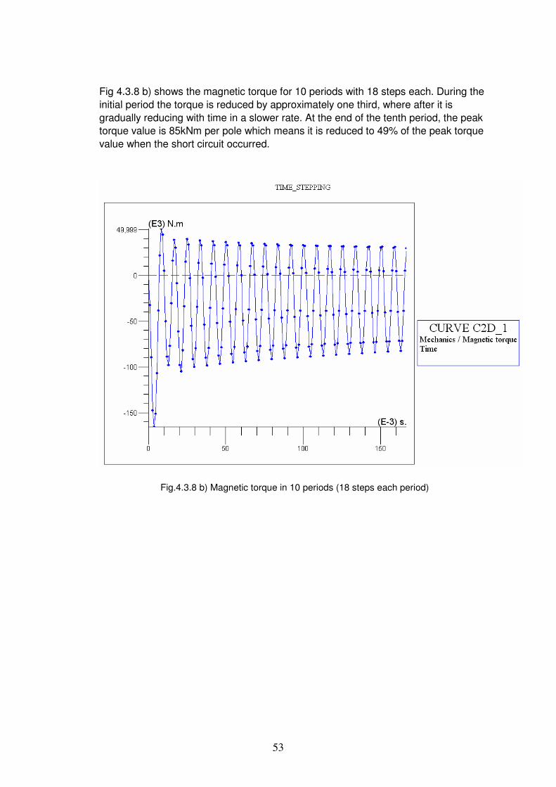
Fig 4.3.8 b) shows the magnetic torque for 10 periods with 18 steps each. During the initial period the torque is reduced by approximately one third, where after it is gradually reducing with time in a slower rate. At the end of the tenth period, the peak torque value is 85kNm per pole which means it is reduced to 49% of the peak torque value when the short circuit occurred.
Fig.4.3.8 b) Magnetic torque in 10 periods (18 steps each period)
54
The phase current
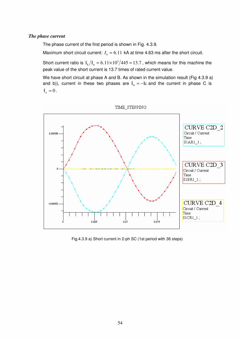
The phase current of the first period is shown in Fig. 4.3.9.
Maximum short circuit current: 11.6=kI kA at time 4.63 ms after the short circuit.
Short current ratio is 7.134451011.6II 3nk =×= , which means for this machine the
peak value of the short current is 13.7 times of rated current value.
We have short circuit at phase A and B. As shown in the simulation result (Fig 4.3.9 a) and b)), current in these two phases are IcIb −= and the current in phase C is
0Ia = .
Fig.4.3.9 a) Short current in 2-ph SC (1st period with 36 steps)

55
Fig 4.3.9 b) below shows the phase current for the first 10 periods with18 steps each.
During the initial period the currents in phase b with short circuit are reduced from 6.11kA to around 4.75kA which is approximately 22.2% reduced. After that it is also gradually reducing with time in a slower rate as the torque. At the end of the tenth period, the peak current value is 4.45kA in phase b which means it is reduced to 72.8% of the peak current value for the same phase when the short circuit occurred.
Fig. 4.3.9 b) Phase current in 10 periods with 18 steps in each period

56
4.4 Analysis of air gap length In this part, analysis of the influence of air gap length is performed. The goal in this part is to study about how the airgap length can influence the magnetic field. All of the results are gotten in no load case. The simulations in this part are for 20mm, 30mm, 40mm (normal) and 49mm air gap length. Longer air gaps could not be set which means that there is some limit in the rotor part file. This could be a point of improvement in future work.
In Fig 4.4.1, the path used to calculate flux density along the middle line of the air gap is drawn in purple.
In this part, we use rated values: nS =17 MVA, nU =22.4 kV and f=60 Hz. Simulations are running under no-load case.
From different colours in Fig 4.4.1, higher flux density value is shown with brighter colour. This is the result of no-load simulation for a VHV machine with 20mm air gap when the field current is the right value to make stator voltage equal to the rated value.
Fig 4.4.1 Flux density along the a path in the centre of different air gap lengths (air gap of 20mm shown)
As is shown in the curves in Fig 4.4.2, the values of flux density along the path is decreasing while the airgap length is increasing. The fundamental harmonics of different airgap length are similar. However, the harmonics in the 20mm air gap are the largest while the lowest harmonics were found in the 49mm air gap. For larger airgap, there is more flux leakage in the airgap which means less flux density.

57
Fig 4.4.2 Flux density along the central line in different airgaps (normal component)
The table 4.4.1 below shows the differences of harmonic influence and field current If while changing the airgap length.
In no load case, for getting the rated stator voltage, we can see from Table 4.4.1 below that the field current is increased while increasing the air gap. And thus RI2 loss increase in the field windings.
For the harmonics, with larger air gaps the slotting influences the air gap flux less, so the harmonics decrease.
Table 4.4.1
Airgap length (mm) Harmonic influence fI A
20 biggest 245
30 2nd biggest 295
40 2nd least 337
49 least 505
58
5 CONCLUSIONS As a definitely new design in ABB, the cable wound VHV (very high voltage) salient pole synchronous machine is directly driven by a ABB HVDC-Light inverter and used on oil platforms.
To find more cost-effective designs, a design tool is necessary. 2D FEM programs, Python language (model and mesh the geometry) and Delphi (control the simulation flow) were used to define the problem, design the software, program and debug for building the model in this tool.
The model has been integrated in the ABB simulation program, SynFEM, which is a FEM platform for two types of simulation analysis of magnetostatics and time-stepping, for ABB synchronous machines. The model has been tested on a typical design of cable synchronous machines designed by ABB Machines and the two simulation cases of magnetostatics (no-load and load point) and the three simulation cases of time-stepping (no-load, current source, 2-ph short circuit) are all achievable.
The integration made it easier to use the VHV model both conveniently and efficiently in a designer's environment. The model can be used for optimizing and testing of existing machine designs as well.
6 FUTURE WORK In the future, key designs, like the phase condition of the VHV machine, may be modified for matching different conditions. Files for those conditions must be updated accordingly. Examples of such updates are:
Python file Alloc1cable.py is planned to be linked to a table in the interface (SynFEM) to show the phase condition setting of each cable for the universal phase location.
HSN1, a parameter in the interface of the stator which is not avaliable in the VHV machine case, can still influence the load point result during calculation. This will then influence the current source results in subsequent time stepping calcuations. This parameter will be set as modifiable in order to remove this bug.
This program could be used for the optimization of VHV machines, for example by simulations of influence of bolt conditions in the stator or different machine materials (stator or rotor) on magnetic field, losses, etc.
The position of the bolts at the teeth side could be changed or even removed for an optimized design (both electrical and manufacturing points of view).
The material of the stator core, (can be found in the SynFEM interface of stator ‘core and slot’) is also an interesting part to investigate further.

59
REFERENCES
Technical papers and reports [1] Tom F. Nestli, Lars Stendius, Magnus J. Johansson, Arne.Abrahamsson, Philip C. Kjaer, “PoweringTroll with HVDC Light™” (Photo: Øyvind Hagen, Statoil), ABB Review Special report on POWER TRANSMISSION (November 2003), pp 53-56
[2] M. Leijon, F. Owman, S. Johansson, T. Karlsson, S. Lindahl, C. Parkegren and S. Thoren,, “PowerformerTM- The prototype and beyond”, Power Engineering Society Winter Meeting, 2000 IEEE, Volume 1, 23-27 Jan.. 2000, pp. 139-144 vol. 1.
[3] R. Dettmer, “The heart of a new machine”, IEEE Review, Volume 44, Issue 6, 19 Nov. 1998, pp. 255-258.
[4] M. Leijon, S. Johansson, F. Owman, S. Alfredson, T. Karlsson, S. Lindahl, C. Parkegren and S. Thoren, PowerformerTM - Experiences from the Application of Extruded Solid Dielectric Cables in the Stator Winding of Rotating Machines, Power Engineering Society Winter Meeting, 2000 IEEE, Volume 1, 23-27 Jan.. 2000, pp. 736-744 vol.1.
[5] S. Alfredson, B. Hernnas and H. Bergstrom. “Assembly of generators with rated voltage higher than 100 kV”, Power System Technology, 2000. Proceedings. PowerCon 2000. International Conference on Volume 1, 4-7 Dec. 2000, pp, 189 - 193 vol.1
[6] S. Lindahl, “Improved control of field current heating for voltage stability machine design-PowerformerTM”, Power Engineering Society Winter Meeting, 2001. IEEE Volume 1, 28 Jan.-1 Feb. 2001, pp. 209 – 214 vol.1.
[7] J. Ohlsson, “Ventilation Flow in Salient Pole Synchronous Machines by Computational Fluid Dynamics”, Master thesis report, Uppsala University, 2007-03-02, 89 p
[8] Hughes A., “Electric Motors and Drives” Published by Elsevier Ltd 2006
[9] S. Lundmark, ‘’hand out of synchronous machines’’, Chalmers University of Technology
Website [10] http://www.cedrat-groupe.com/en/software-solutions/flux.html