Embed Size (px)
Citation preview
UDC 539.4
FEM Analysis of Stress Distribution in the Hermetic Harmonic Drive
Flexspline
J. Pacana,1
W. Witkowski,2
and J. Mucha3
Rzeszów University of Technology, Rzeszów, Poland
ÓÄÊ 539.4
Ñê³í÷åííîåëåìåíòíèé àíàë³ç ðîçïîä³ëó íàïðóæåíü ó ãåðìåòè÷íîìó
ãàðìîí³÷íîìó ðåäóêòîð³ ç ãíó÷êèì ñïëàéíîì
ß. Ïàöàíà, Â. ³òêîâñê³, ß. Ìóõà
Æåøóâñüêèé òåõíîëîã³÷íèé óí³âåðñèòåò, Æåøóâ, Ïîëüùà
Âèêîíàíî ÷èñåëüíèé ðîçðàõóíîê íàïðóæåíü ó ãíó÷êîìó ñïëàéí³ çóá÷àòî¿ ïåðåäà÷³ ãàðìîí³÷íîãî
(õâèëüîâîãî) ðåäóêòîðà. Çóá÷àòå ê³ëüöå ó ãíó÷êîìó ñïëàéí³ ÷åðåç ñêëàäíó ãåîìåòð³þ ìîäå-
ëþâàëîñü ó âèãëÿä³ ê³ëüöÿ. Âèñîòó ê³ëüöÿ ïðèéìàëè ç óðàõóâàííÿì íàïðóæåíîñò³ â çóáöÿõ. Äëÿ
âèâ÷åííÿ âïëèâó ð³çíèõ òèï³â õâèëüîâèõ ãåíåðàòîð³â íà ðîçïîä³ë íàïðóæåíü ó ãíó÷êîìó ñïëàéí³
ðîçãëÿäàëè ìîäåë³ ç äâîìà òà ÷îòèðìà ðîëèêàìè, åêñöåíòðèêîì àáî äèñêîì. Ðîçðàõóíîê
íàïðóæåíü âèêîíóâàëè äëÿ äâîõ âàð³àíò³â: áåç îáåðòàëüíîãî ìîìåíòó òà ç îáåðòàëüíèì
ìîìåíòîì, ùî â³äïîâ³äຠðåàëüíèì óìîâàì ðîáîòè ãåðìåòè÷íîãî ãàðìîí³÷íîãî ðåäóêòîðà.
Êëþ÷îâ³ ñëîâà: ãåðìåòè÷íèé ãàðìîí³÷íèé (õâèëüîâèé) ðåäóêòîð, ðîçïîä³ë íàïðóæåíü,
ñê³í÷åííîåëåìåíòíèé àíàë³ç.
Introduction. Production automation requires the use of high-quality propulsion
systems for industrial robots with high reliability, as well as adequate rigidity and minimum
weight of housing and framework of manipulators [1]. A power transmission system of
manipulators and industrial robots should have several prominent features, one of these
being its high total gear ratio, which is critical for minimizing its size and weight [2].
Therefore, application of harmonic drives in robots transmission systems is very instrumental
to achieve this goal. For this type of systems, a high stiffness during the loading process is
required from the propulsion system components and, especially, the flexspline teeth rim
[3]. The operation of a propulsion system with a harmonic drive is controlled by the work
kinematic of the latter [4].
In the strength analysis of harmonic drive, determination of stress distribution in it is
an extremely important issue: it is mandatory for the optimal designing of propulsion
systems used in industrial robots or space industry [5]. During the modeling in CAD
systems, a critical issue is the accuracy of tooth side mapping [6]. Similar to the classical
gears, the shape of flexspline teeth rim controls the gear operation conditions, especially
under the oscillation conditions [7–9]. A number of research papers, including those
mentioned earlier, concern the vibration analysis [2–5, 10–12], new models for more
accurate characterization of propulsion system, and the tooth profile accuracy effect on the
gear teeth mapping [13]. Stiffness, non-linear hysteresis, and friction affect the kinematic
© J. PACANA, W. WITKOWSKI, J. MUCHA, 2017
ISSN 0556-171X. Ïðîáëåìû ïðî÷íîñòè, 2017, ¹ 3 51

parameters of the gear transmission [14]. During the gear operation, an increase in stresses
is accompanied by a temperature rise due to contact/lubrication-induced processes. The
respective thermomechanical analysis of flexspline teeth rim of harmonic drive was
reported in [15]. Harmonic drive design solution effect on the gear stiffness during the load
application was studied in [16, 17]. Depending on the number of working teeth, which are
currently involved in the load transfer, the strain distribution in the flexspline is changing
significantly [18]. Hence, it is expedient to analyze the sleeve (flexspline) design impact on
the stress distribution during the torque load transfer.
As shown in Fig. 1, a harmonic drive consists of three main components: rigid
circular spline (inner teeth), flexspline (external teeth), and wave generator. The rotation of
the generator causes a radial deformation of the flexsline. Due to the mismatch in the
number of gear teeth (usually equal to 2), the flexspline moves relative to the circular
spline. For this type of gear transmission, two regions of teeth engagement are observed (in
the major axis).
In this paper, a mathematical model of shell component is reduced to the analysis of
stress distribution due to the torque load application to a typical cam generator. Since the
analytical determination of stresses for an assembly process involving complex parts is very
difficult, the FEM analysis is performed for the zero torque load and the typical torque load
value T1 150� N�m. The numerical simulation allows one to assess the stress distribution
and stress values in the specific areas of the flexspline. In numerical simulation, stress
distributions were obtained for different types of wave generators: two-roller, four-roller,
cam and disk ones. In the calculation of the stress distribution in the flexspline, contact
elements between models were applied (generator was a master part and flexspline was a
slave part). The proper deformation of the flexspline for each generator models was
obtained by applying the generator radial displacement.
Sleeve Mechanical Shell Model. Stress analysis of a thin-walled cylindrical shell
loaded by pressure was presented by Makhutov et al. [19]. However, in the case of
application of additional rings (structural or stiffening walls), the model mathematical
description becomes quite problematic, since the additional stiffening walls influence the
thin-walled sleeve deformation. The experimental study of this problem was presented by
Shektman [20].
In terms of the Kirchhoff–Love theory [21], the sleeve is described as a shell, with an
ideal mechanical contact being applied between the shell and plate. The stresses in the
cylindrical shell are derived as follows:
J. Pacana, W. Witkowski, and J. Mucha
52 ISSN 0556-171X. Ïðîáëåìû ïðî÷íîñòè, 2017, ¹ 3
Fig. 1. Typical harmonic drive components.

��
��
�
�
z t t
t t
z
hN
hM
hN
hM
� ��
�
�
� ��
�
�
1
23
1
23
1 2 1
2 2 2
,
,
��
� ��
�
� 1
2312 2 12
hS
hH ,
where 2h is the shell thickness.
The equilibrium equations in displacements have the following form:
D u
z R
u
z
w
z
Dt t0
2
21
2
22 0
1�� �
�
�
�
�
���
�
����
�
�
�
� �
� ��
�
�t
R
u u
z2 10
21
2
22
( ),
��
�
�
� ��
�
��
�
���
1
1
10
2
22
2
21
R
D
R
u w u
z
t t
( )��
�
�
� �
�
���
�
��
�
��
�
����
������
��
�
�
� �
D
R
u
z
u
z
t02
12
2
22 1
1
( )�
�
� ��
�
�
� ��
�
� �
�
��
�
���
D
R R
wu
w
z
Dt t t t1
2 2 2 2
3
2
11 2�
��
�
����
���
(10
2 2 2
��
�
�
� �
� �
�
�
��
),
R z
wu
t
D
R
u w
R
u
zD R
w
z R
wt tt
t0
2
2 11
4
4 2
4
1
1
�� �
�
�
� � �
�
�
����
�
�
�
� � t
z
u
z� ��
�
� ��2 2
32
2�
�
�
�
�
���
�
����
��
��
�
� �
2 1 113
2 21
2
3
3
D
R z
wu
D
R R
wt t t t( )� �
���
�
��
�
��
�
���
�
�
� �
�
��
�
���u
w
z
t2
4
2 2��
� ��
�� ��
�
� �
�
��
�
��D
R
wu
w
zt
t t1 2
2
2 2
3
2
1 �
��
�
����
���,
where D Eht0 2� and DEh
t1
3
2
2
3 1�
��are tensile and bending stiffness values, respectively.
Taking into account the shell boundary conditions: z� 0 to w wt � , M t1 0� , and
N t1 0� ; z�1 (an ideal mechanical contact with the plate), after integration and
substitution of dimensionless values we get:
d w
dxw
40
4 04 0� � .
Thus, stresses in the shell are
��
ztD R d w
a h��
3
8
02
0
2 3,
��
� � ��
�
� 1
232 2 2h
N Mh
t t .
FEM Analysis of Stress Distribution …
ISSN 0556-171X. Ïðîáëåìû ïðî÷íîñòè, 2017, ¹ 3 53
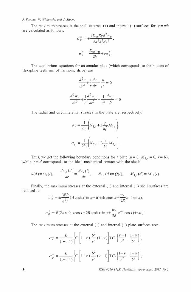
The maximum stresses at the shell external (�) and internal (�) surfaces for ���h
are calculated as follows:
��
ztD R d w
a h dx
� � �3
8
02
0
2 2 2,
� ���� �� �
D w
h
tz
0 0
2.
The equilibrium equations for an annular plate (which corresponds to the bottom of
flexspline teeth rim of harmonic drive) are
d u
dr r
du
dr
u
r
2
2 2
10� � � ,
d w
dr r
d w
dr r
dw
dr
p p p3
3
2
2 2
1 10� � � .
The radial and circumferental stresses in the plate are, respectively:
��
r p ph
Nh
M� ��
�
�
1
23
11
12 1 ,
��
� � ��
�
�
1
23
12
12 2
hN
hMp p .
Thus, we get the following boundary conditions for a plate (u� 0, M p1 0� , r b� );
while r d� corresponds to the ideal mechanical contact with the shell:
u d w lt( ) ( ),�dw d
dr
dw l
dz
p t( ) ( )
,� N d Q lp1 ( ) ( ),� M d M lp t1 1( ) ( ).�
Finally, the maximum stresses at the external (�) and internal (�) shell surfaces are
reduced to
� zxER
a hA x x B x x
w
Re x� ��� � �
3
22( cosh sin sinh cos sin ),
*
� ���� � �� � � �E A x x B x x
w
Re xx
z( sinh cos cosh sin cos ) .*
2 22
The maximum stresses at the external (�) and internal (�) plate surfaces are:
��
� �� �
r
EC
b
rC
r b
� ��
� � ��
��
�
��
����
�
( )( )
11 1
1 12 1
2
2 3 2 2�
�
���
��
���
��,
��
� �� �
�� �
�� � �
�
��
�
��
����
�EC
b
rC
r b( )( )
11 1
1 12 1
2
2 3 2 2�
�
���
��
���
��,
54 ISSN 0556-171X. Ïðîáëåìû ïðî÷íîñòè, 2017, ¹ 3
J. Pacana, W. Witkowski, and J. Mucha

where
AL
n ps k t pq mn� � � � � �1
[( )( ) ( )( )], ! " #" $!
BL
n ps q m nk pt� � � � � �1
[( )( ) ( )( )], " ! #" $!
Cn
s At Bq1
1� � �( ), C Aq Bt3
1� � �!
#( ),
L pq mn q m nk pt k t� � � � � �( )( ) ( )( )," ! ! "
k� 2sinh cos ,% % m� 2cosh sin ,% % q� �2(cosh cos sinh sin ),% % % %
t� �2(cosh cos sinh sin ),% % % % sw
Re� ��*
(cos sin ),% % %
# % %%� ��w
Re
*(cos sin ), %%� �w
Re
*cos , $ %%� �w
Re
*sin ,
"�
� ��
�
��
��
�
�
2
3 1
1 12
13
2 2 2
a h
hR d b( ), p
Rd
b
d� �
�
�
�
1 2
, na h
h
b
d�
�� �
��
��
�
��
2
11
12
1
2
2
2( )
( ),
��
�
xaz
R� , a
R
h�
�3 1
4
2 2
24
( ),
�!
�
�� �
�
�
�
��
�
��
1 1 1
1 2a d
d
b
( )
( ), %�
al
R, 0& &z l.
Experimental Methodology and Scope Research.
FEM Methodology. Numerical simulation using 3D models is quite time-consuming
due to the large number of finite elements. In view of the harmonic drive symmetry by the
major and minor axes, the flexspline CAD model was designed for its half, which is
symmetrical along the minor axis. The generator variant CAD models were constructed.
The main goal was to study the effect of a wave generator design on the stress distribution
in the flexspline teeth rim of harmonic drive. Hence, a simplified model of the gear teeth,
with an unchanged shape of the remaining flexspline, was adopted. In the simplified model,
teeth were replaced by a ring of hn thickness corresponding to the residual stress values
of teeth. Based on the design calculations and the literature, the K y coefficient, which
takes into account the residual stresses, was set at K y � 0.7. Hence, the total thickness of
the ring was determined as hn � 1.8 mm. This simplification reduces the number of finite
elements used for discretization of the flexspline-wave generator arrangement. In the
numerical discretization process, hexahedral and contact elements were used.
In the FEM model, symmetrical deformation of the flexspline teeth rim was adopted
for deformation by wave generator and for analysis with torque load applied. Hence, the 3D
flexspline model for the calculation of stress distribution was used (Fig. 2). To simulate the
true operation conditions of the harmonic drive, the respective boundary conditions were
assumed. Nodes in the cross-sectional plane, indicated as B in Fig. 2, were assumed to
displace only in the XY plane, while the nodes of the flexspline flange (indicated as D in
Fig. 2) were fixed. The model’s Z axis corresponded to the major axis, and X axis to the
minor one of the wave generator. Thus, displacements of the wave generator model were
allowed only in the plane perpendicular to the major axis (nodes indicated as C in Fig. 2).
ISSN 0556-171X. Ïðîáëåìû ïðî÷íîñòè, 2017, ¹ 3 55
FEM Analysis of Stress Distribution …

To study the effect of the wave generators of different types on the stress distribution
in the flexspline, the following models were constructed: two-roller, four-roller, cam, and
disk ones. After the model discretization by using hexahedral elements, calculations of
flexspline deformation for each wave generator model were performed. The wave generator
models and torque load applying are presented in Fig. 3 in the form of teeth ring cross
sections.
56 ISSN 0556-171X. Ïðîáëåìû ïðî÷íîñòè, 2017, ¹ 3
Fig. 2. Flexspline model used in FEM calculation.
a b
c d
Fig. 3. Hermetic harmonic drive parts for stress analysis of flexspline teeth rim deformed by wave
generator: (a) two-roller; (b) four-roller; (c) cam; (d) disk.
J. Pacana, W. Witkowski, and J. Mucha

The stress calculation were performed for two variants. At the first step of numerical
analysis, the stress distribution in the flexspline teeth rim deformed by each wave generator
was obtained. At the second step, the torque load T1 150� N�m was applied to the
models, which corresponded to load value in the true operation conditions of the harmonic
drive.
Stress Experimental Measurement. Stress distribution results from FEA were verified
by the experimental data for the respective flexspline parts deformed by cam wave
generator. In each cross section, the circumferential ( �1 ) and axial ( � 2 ) stress distributions
were compared for the harmonic drive loaded by torque load T1 150� N�m. To ensure the
same operation conditions for FEA and tests, the same geometry, dimensions, and torque
loads were used.
For the strain measurements using the extensometer method, the flexspline was
prepared for experimental tests: strain gauges were glued to the flexspline surface(Fig. 4a).
For this purpose, theTF-1 strain gauges manufactured by Tenmex were adhered by the
TB-1731 cyanoacrylate glue. To protect the strain gauges and soldering points against
adverse environmental conditions and ensure their protection from mechanical damage, the
Silten silicon and adhesive tape were used to cover these.
ISSN 0556-171X. Ïðîáëåìû ïðî÷íîñòè, 2017, ¹ 3 57
FEM Analysis of Stress Distribution …
a
b
Fig. 4. Flexspline teeth rim of the hermetic harmonic drive: (a) adhered foil strain gauges; (b) scheme
of strain gauge’ arrangement.

In Fig. 4b, the arrangement of strain gauges in reference to the coordinate system are
depicted. Assuming a zero angle for the plane of wave generator major axis, which divides
the flexspline calculation model into two quarters, the one in the perpendicular plane with
the minor axis is 90'. In the selected cross sections (Fig. 4b), the stress values were
determined in two steps. The first measurement was performed for parallel plane to the
model Y axis, which corresponded to the direction of the axial stresses � 2. The
circumferential stresses �1 were measured in the plane, which was normal to the wave
generator major axis. The experimental measurements were done only for the flexspline
teeth rim deformed by the cam wave generator with the applied torque load (T1).
The positive stress values corresponded to the tensile load, and vice versa. The stress
values obtained by the numerical simulation were assigned to the flexspline outer surface
nodes so as to correspond to the respective cross section in the experimental measurements.
Results and Discussion. The differences in the stress distribution can be observed
in the conical part of the flexspline tooth rim (Fig. 5). The maximum level of stresses
(700 MPa) on the teeth ring was observed in the roller-flexspline contact zone. For the
two-roller wave generator, this zone was located in the major axis vicinity, while for the
four-roller wave generator, the revealed zones with the maximum stress corresponded to the
range of angles (� 25–30' to the major axis. A high level of stresses was also obtained in
all zones where the flexspline teeth rim changed it shape and in the teeth ring edges.
The torque load caused a significant stress increase in the central zone of the
flexspline conical part. The stress distribution changes were asymmetrical, because the
stress increase was observed at the generator major axis, for which the torque load was
applied, while for the opposite side of the generator major axis, the decreased stress level
was observed. Such stress variation is not advantageous for the component operation, since
it implies a significant deformation of the flexspline loaded with torque and thus, may
aggravate the teeth heavy-load operational conditions.
58 ISSN 0556-171X. Ïðîáëåìû ïðî÷íîñòè, 2017, ¹ 3
J. Pacana, W. Witkowski, and J. Mucha
c d
a b
Fig. 5. Stress distribution in the flexspline teeth rim of hermetic harmonic drive deformed by wave
generator (150 N�m torque load): (a) two-roller; (b) four-roller; (c) cam; (d) disk.

In case of a roller wave generator application, the stress distribution in the flexspline
teeth rim is disadvantageous, and the stress level is high. The stress distribution in
harmonic drives unloaded with torque load with cam and disk generators were very similar
to each other. After applying the torque load the numerical model, the stress level slightly
increased but the stress distribution did not change. This is due to the fact that the cam
generator contacted with flexspline along the entire cam circumference, so the additional
deformation under the torque load was blocked. Thus, application of a cam generator
allows one to obtain the deformation, which would guarantee a proper operation of its
teeth. For this generator, the maximum stress levels corresponding to the torque load were
lower than those of any other generator types used in this study.
In the numerical model, the highest stress values of about 400 MPawere obtained in
the first and fourth cross sections of the flexspline conical part (Fig. 6a). In cross section 4
(Fig. 4b), which was located close to the gear teeth in the major axis (90'), the tensile
stresses were obtained, while in the minor axis plane the compressive ones were obtained.
And for cross section 1 located close to the flexspline flange, the compressive stresses
occurred in the major axis plane, and tensile ones in the minor one. In two other cross
sections located close to the center of the conical part, the stresses directed along Y axis
were significantly lower and did not exceed 100 MPa. The stress values in the cylindrical
part (Fig. 6b) co-directed with the flexspline axis were lower than those in the conical part
(Fig. 6a), and approached 300 MPa. The highest values were observed in cross section 5,
which was located close to the gear teeth, and their values decreased with the distance from
from gear teeth.
For the same flexspline model in 1–8 cross sections perpendicular to the major axis,
the circumferential stresses were measured (Fig. 6). For the first four of analyzed cross
sections, the highest stress values exceeding 800 MPa were obtained in cross section
located close to the gear teeth (Fig. 6a). In the flange area (cross section 1), the stress level
was also high (400 MPa) in the major and minor axes’ zones. For both axial stresses and
circumferential stresses, the specific stress distribution due to the applied torque load (T1)
was observed (Fig. 6a). In the cross section closest to the gear teeth, the highest stress value
was observed in the major axis plane ((� '0 ).
In case of axial stresses in the conical part, a good agreement of the experimental and
numerical simulation results was obtained (Fig. 7a). The waveforms were similar to each
ISSN 0556-171X. Ïðîáëåìû ïðî÷íîñòè, 2017, ¹ 3 59
FEM Analysis of Stress Distribution …
a b
Fig. 6. Axial and circumferential stresses in flexspline teeth rim of hermetic harmonic drive deformed
by cam wave generator at the torque load of 150 N�m.

other, although small differences in the stress value were obtained. The above differences
may be attributed to both limited FEM accuracy and limited possibilities of strain
measurement via strain gauges. Moreover, the axial stresses in cross section 4 (from�90 to
� '70 and from 90 to 70') have a different waveform, see Fig. 8a. The reason of this
difference may be that cross section 4 is located close to the point of the flexspline shape
variation (from conical to cylindrical part).
Verification of the results obtained for the cylindrical part of the flexspline teeth rim
revealed smaller differences in the stress distribution. In case of cross sections in the
cylindrical part of the flexspline, the agreement of esperimental and numerical results was
the highest (Fig. 8b), due a simple geometry and better measurement conditions for such
shapes. The tension–rotation angle characteristics were slightly different for stresses in
cross sections 5 and 6 (Fig. 7b), which may be attributed to the flexspline shape variation
effect on the stress distribution in these cross sections. The computational specifics could
60 ISSN 0556-171X. Ïðîáëåìû ïðî÷íîñòè, 2017, ¹ 3
J. Pacana, W. Witkowski, and J. Mucha
Fig. 7. Axial stresses in specified cross sections according to the rotation angle for conical (a) and
cylindrical (b) parts.
a b
a b
Fig. 8. Circumferential stresses in specified cross sections according to the rotation angle for
conical (a) and cylindrical (b) parts.
also ensure the above differences: the stress distribution was measured in the mesh nodes,
which made it possible to use more measurement points than in previous cases.
Conclusions. Knowledge of the stress distribution in the flexspline teeth rim of
hermetic harmonic drive makes possible the most appropriate selection of a wave generator
for reducing the stress level, especially in the place of shape geometry variation.
The use of a cam generator yields the most adequate (i.e., the most accurately
controlled) deformation among the analyzed generators types, which would guarantee the
optimal teeth engagement of flexspline and circular spline.
After applying the torque load to the numerical models, a sharp change in the stress
distribution was observed for the roller and disc wave generators. In the zones with a high
level of stresses, the stress values increased by approximately 30% after applying the
torque load.
A high level of stresses was also observed in all zones where the flexspline teeth rim
changed it shape, as well as in the teeth ring edges. In respective cross sections, the
maximum stress values were co-directed with the major and minor axis of the flexspline
teeth rim.
The application of experimental stress/strain measurements via strain gauges to to the
verification of numerical simulation results was found to have its test limitations. However,
successful stress measurements in the particular cross sections of the flexspline teeth rim
were obtained in this work. A feasibility of the proposed numerical model was verified by
the test results.
Ð å ç þ ì å
Ïðîâåäåí ÷èñëåííûé ðàñ÷åò íàïðÿæåíèé â ãèáêîì ñïëàéíå çóá÷àòîé ïåðåäà÷è ãàðìî-
íè÷åñêîãî (âîëíîâîãî) ðåäóêòîðà. Çóá÷àòîå êîëüöî â ãèáêîì ñïëàéíå èç-çà ñëîæíîé
ãåîìåòðèè ìîäåëèðîâàëîñü â âèäå êîëüöà. Âûñîòó êîëüöà ïðèíèìàëè ñ ó÷åòîì
íàïðÿæåííîñòè â çóáüÿõ. Äëÿ èçó÷åíèÿ âëèÿíèÿ ðàçëè÷íûõ òèïîâ âîëíîâûõ ãåíå-
ðàòîðîâ íà ðàñïðåäåëåíèå íàïðÿæåíèé â ãèáêîì ñïëàéíå ðàññìàòðèâàëè ìîäåëè ñ
äâóìÿ è ÷åòûðüìÿ ðîëèêàìè, ýêñöåíòðèêîì è äèñêîì. Ðàñ÷åò íàïðÿæåíèé âûïîëíÿëè
äëÿ äâóõ âàðèàíòîâ: áåç âðàùàþùåãî ìîìåíòà è ñ âðàùàþùèì ìîìåíòîì, ñîîò-
âåòñòâóþùèì ðåàëüíûì óñëîâèÿì ðàáîòû ãåðìåòè÷åñêîãî ãàðìîíè÷åñêîãî ðåäóê-
òîðà.
1. T. Markowski, J. Mucha, and Witkowski W., “FEM analysis of clinching joint
machine’s C-frame rigidity,” Eksploatacja i Niezawodnosc – Maintenance and
Reliability, 15, No. 1, 51–57 (2013).
2. M. Haã and W. Ostapski, “Dynamics of planar manipulators with flexible links driven
by motors with harmonic drives,” Mach. Dyn. Probl., 22, 19–31 (1998).
3. T. Tjahjowidodo, F. Al-Bender, and H. Van Brussel, “Theoretical modelling and
experimental identification of nonlinear torsional behaviour in harmonic drives,”
Mechatronics, 23, No. 5, 497–504 (2013).
4. H. Dong, K-L. Ting, and D. Wang, “Kinematic fundamentals of planar harmonic
drives,” J. Mech. Design, 133, No. 1, 011007 (2011), DOI:10.1115/1.4003140.
5. Z. Chao, W. Shaoping, W. Zimeng, and W. Xingjian, “An accelerated life test model
for harmonic drives under a segmental stress history and its parameter optimization,”
Chinese J. Aeronaut., 28, No. 6, 1758–1765 (2015).
6. T. Markowski, J. Mucha, and W. Witkowski, “Automating the modelling process of
involute spur gears with straight teeth,” Adv. Sci. Technol. Res. J., 7, No. 19, 66–69
(2013).
FEM Analysis of Stress Distribution …
ISSN 0556-171X. Ïðîáëåìû ïðî÷íîñòè, 2017, ¹ 3 61

7. T. Hidaka, T. Ishida, Y. Zhang, et al., “Vibration of a strain-wave gearing in an
industrial robot,” in: Proc. of the Int. Power Transmission and Gearing Conf. (1990),
pp. 789–794.
8. R. Bogacz and S. Noga, “Free transverse vibration analysis of a toothed gear,” Arch.
Appl. Mech., 82, 1159–1168 (2012).
9. T. Marilier and J.A. Richard, “Non-linear mechanic and electric behavior of a robot
axis with a ‘‘harmonic-drive’’ gear,” Robot. Comput. Integr. Manuf., 5, Nos. 2-3,
129–136 (1989).
10. D. P. Volkov and Y. N. Zubkov, “Vibration in a drive with harmonic gear
transmission,” Russ. Eng. J., 58, No. 5, 17–21 (1978).
11. C. Preissner, T. J. Royston, and D. Shu, “A high-fidelity harmonic drive model,” J.
Dyn. Syst. Meas. Control., 134, No. 1, 011002, DOI:10.1115/1.4005041.
12. Y. Fan, H. Wang, and D. Song, “Kinematics computerized simulation for conjugate
tooth profiles of harmonic drive,” J. Nanjing Univ. Sci. Technol., 34, No. 5, 448–450
(2002).
13. O. Kayabasi and F. Erzincanl, “Shape optimization of tooth profile of a flexspline for
a harmonic drive by finite element modeling,” Mater. Design, 28, No. 2, 441–447
(2007).
14. N. Kircanski, A. A. Goldenberg, and S. Jia, “An experimental study of nonlinear
stiffness, hysteresis, and friction effects in robot joints with harmonic drives and
torque sensors,” in: T. Yoshikawa, F. Miyazaki (Eds.), Lecture Notes in Control and
Information Sciences, Vol. 200, LNCIS (1993), pp. 326–340.
15. L. Liu, B. You, P. Wang, et al., “Heat-structure coupling analysis of harmonic drive
under different thermal loading,” Int. J. Control Autom., 11, 201–2010 (2015).
16. P. Folegà and G. Siwiec, “Numerical analysis of selected materials for flexsplines,”
Arch. Metall. Mater., 1, 185–191 (2011).
17. H. Gao, H. Zhuang, Z. Li, et al., “Optimization and experimental research on a
new-type short cylindrical cup-shaped harmonic reducer,” J. Cent. South Univ., 19,
1869–1882 (2012).
18. Y. S. Hareesh and J. Varghese, “Design and analysis of flex spline with involute teeth
profile for harmonic drive mechanism,” Int. J. Eng. Res. Technol., 4, No. 12, 613–618
(2015).
19. N. A. Makhutov, L. I. Gladshtein, and Yu. M. Grachev, “Failure of models of
thin-walled shells when loaded by internal pressure,” Strength Mater., 8, No. 2,
123–129 (1976).
20. Yu. V. Shektman, “Experimental investigation of the stability of cylindrical shells
with stiffening rings, under the action of external pressure,” Strength Mater., 1, No. 6,
650–655 (1969).
21. S. Timoshenko and S. Woinowsky-Krieger, Theory of Plates and Shells, McGraw-
Hill Book Company (1959).
Received 10. 01. 2017
J. Pacana, W. Witkowski, and J. Mucha
62 ISSN 0556-171X. Ïðîáëåìû ïðî÷íîñòè, 2017, ¹ 3