Embed Size (px)
Citation preview

L-1633 Rev. 3 © OmniGuide, Inc. Page 1
To be used with: OmniGuide Catalogue Number: FELS-25A,
FELS-25A-E, FELS-25A-S2, FELS-25A-S3, FELS-25A-S4.
��
FELS-25A,
BeamPath with IntelliGuide™ Fiber Enabled CO2 Laser
Users Manual�
®
������������ ���������������
������������������������ !!! """ ��!������ "�# $$� !����%&�
URL: http://www.omni-guide.com
0483
A.R.C. LASER GmbH Bessemerster. 14
D-90411 Nurnberg, Germany Tel. 49 911 21779-0
L-1633 Rev. 3 © OmniGuide, Inc. Page 2
Caution: Federal law restricts this device to sale by or on the order of a physician or dentist.
•� This article is covered by the following patents: U.S. Patent No. 7349589, 7167622, 7331954, 7991258. OmniGuide, Inc. (OG) is not responsible for injury or damage resulting from improper use of the system. If there is any doubt concerning the use of the system or the User’s Manual, contact OG immediately for assistance.

L-1633 Rev. 3 © OmniGuide, Inc. Page 3
Table of Contents
� ��������������� ��������'�&����(��)�*��� �����������������������������������������������������������������������������������������������������������������"�
����� +��� �,�� ������-������'�����������������������������������������������������������������������������������������������������������������#�
� ���� �������� ����������������������� ,�������� �����(���������������������������������������������������������������������������������������������������������������������������������#�
����� �.�(�/)) �(�������������������������������������������������������������������������������������������������������������������������������������#�
��0�� 1)���������)�-���������������������������������������������������������������������������������������������������������������������������������#�
����� 1)���������)�,����������������������������������������������������������������������������������������������������������������������������������#�
��$�� �� �������)�-���������2�(�������������������������������������������������������������������������������������������������������������������3�
� ���� ��������0���� -������(�)�����(��&���� ���*�� ��(�������������������������������������������������������������������������������������������������
0���� -������(�(4 �)� ���� ��4�((���(��������������������������������������������������������������������������������������������������0�
0�0�� &������'�-������(��������������������������������������������������������������������������������������������������������������������������������0�
� ���� ������������� ,������(�)�����(��&���� ���*�� ��(�������������������������������������������������������������������������������������������������0�
����� �)� �����'�4��� ����������������������������������������������������������������������������������������������������������������������
��0�� 5���*��� �������������������������������������������������������������������������������������������������������������������������������������������
����� /'�4��� �������������������������������������������������������������������������������������������������������������������������������������������
��$�� ��((��4��� ���������������������������������������������������������������������������������������������������������������������������������������
��"�� &��6�,�������������������������������������������������������������������������������������������������������������������������������������������$�
� ������������� �� �������$���� 5�2��/��2����(�������������������������������������������������������������������������������������������������������������������������������$�
$���� �7���������)�2����������������������������������������������������������������������������������������������������������������������������3�
$�0�� ��������,���������(����������&'(����������������������������������������������������������������������������������������
$���� �4�������&4 �)� �����(�)�����(�����������������������������������������������������������������������������������������������������������
� �����������"���� ��(��&�)�'��8������(������������������������������������������������������������������������������������������������������������������$�
"���� �4�� ���&�)�'��������������������������������������������������������������������������������������������������������������������������������������$�
"�0�� /� ��� ���&�)�'�����������������������������������������������������������������������������������������������������������������������������������"�
"���� ,��4���� ����&�����(���.�������,/ ���6������������������������������������������������������������������������������������#�
� ����������� �������������������
� ������ ������� ������ �������

L-1633 Rev. 3 © OmniGuide, Inc. Page 4
!���� ��(���)����(�����7�2���������������������������������������������������������������������������������������������������������������������������!�
!���� &�)�'��((�(����,�����((�2�'������(��&��4������������������������������������������������������������������������������������!�
� ��� � � ����� � ���������!�3���� ���� ��������8������(���������������������������������������������������������������������������������������������������������������������3�
3���� /� ��� ���*�9��,��� �������������������������������������������������������������������������������������������������������������������0��
3�0�� ,��4�((���(��8������������������������������������������������������������������������������������������������������������������0��
3���� 1���������� 6�������������������������������������������������������������������������������������������������������������������������������������0��
3�$�� 5����*���,��� ����������������������������������������������������������������������������������������������������������������������������0��
� ������������� ������������� &9�� 7������(��&'(���������������������������������������������������������������������������������������������������������������������0��
������ �����*�9��&9�� 7�������������������������������������������������������������������������������������������������������������������������0��
���0�� %(������)� ����������������������������������������������������������������������������������������������������������������������������������0��
������ ��������5�2����(��� ����(�)���%(�������������������������������������������������������������������������������������������������
���$�� ��'�������������������������������������������������������������������������������������������������������������������������������������������������
���"�� &'(����4�������������(���� ���4�� �����������������������������������������������������������������������������������������
���#�� *�(� �4����.�&'(���&7���9�������������������������������������������������������������������������������������������������������
� ����� �������� � "�� �������� ��������#�������� ,���������(��� ����(��������������������������������������������������������������������������������������������������������������������������
������ &�����:������������(�����������������������������������������������������������������������������������������������������������������������
���0�� 5�2��1�(4�(�����(��� �����������������������������������������������������������������������������������������������������������������������
� �$%&'(&$&)(��#�������� �.�.�9��������������������������������������������������������������������������������������������������������������������������������������������
������ ������������������������������������������������������������������������������������������������������������������������������������������������0�
���0�� ,���2���������������������������������������������������������������������������������������������������������������������������������������������0�
������ ��(��������������������������������������������������������������������������������������������������������������������������������������0�
���$�� *���(�������������������������������������������������������������������������������������������������������������������������������������������������0�
���"�� /���4���4�����������������������������������������������������������������������������������������������������������������������������������0�
���#�� �����������)�����������������������������������������������������������������������������������������������������������������������������0�
� �*+,-.(/0++'%&1��#���0���� &'(����(�����(���������������������������������������������������������������������������������������������������������������������������0�
13.2.� Password does not work������������������������������������������������������������������������������������������������������������������0�
�0�0�� +��)) �������((������������������������������������������������������������������������������������������������������������������������������
�0���� ��9�4�9��������4�9���(��2(�.������)��7���������5�2��������������������������������������������������������
L-1633 Rev. 3 © OmniGuide, Inc. Page 5
�0�$�� &'(�������7�������������������������������������������������������������������������������������������������������������������������������������
� �$**$&'2��##������� -������'����4���(������������������������������������������������������������������������������������������������������������������������������
������ �(4��(�2����'��)��7�2�'����������������������������������������������������������������������������������������������������������������$�
���0�� ������������)�9������'����������������������������������������������������������������������������������������������������������������������$�
� ���� ��������������#���$���� *� 6�����)��7�('(�������������������������������������������������������������������������������������������������������������������������$�
�$���� &7�44������(��� ����(������������������������������������������������������������������������������������������������������������������������$�
� (**+*�.%/'�3(/)*%4'%+&��#��
� �� ����������������������5���������� ����#��
� ���������������
� �*+3,)'� &6+*7$'%+&������3���� *��� ����8����(�)���%&�����������������������������������������������������������������������������������������������������������������$��
�3���� /���4������7���:��4�(�����.����������������������������������������������������������������������������������������������$��
� �8$74.(�/(*9%)(�*(4+*'����������� �7�(�)�����(�������4�����(�2; ����� 7��������7�����)� ����<(��( ����������������������������������$0�
L-1633 Rev. 3 © OmniGuide, Inc. Page 6
PREFACE This manual is designed to help the user understand and operate the FELS-25A Fiber Enabled CO2 Laser systems. The family of the FELS-25A systems consists of the following versions:
•� FELS-25A, which accepts 110V, 50/60 Hz Electrical input •� FELS-25A-E, which accepts 220V, 50/60 Hz Electrical input.
FELS-25A will refer to all the units (unless the specific units are called out). This manual contains information on the performance and operation of the Laser as well as installation and control methods. The FELS-25A uses a C-LAS medical CO2 Laser manufactured by A.R.C. Laser GmbH (Bessemerstr. 14 D-90411 Nürenberg, Germany, tel. 0049-911-217790) for OmniGuide, Inc. The CO2 Laser is fitted with an adapter that enables the Laser to deliver energy through a flexible optical fiber. The adapter and optical fiber are manufactured by OmniGuide, Inc. The Laser has an integrated gas control system on a cart designed by OmniGuide that holds the Laser, compressed gas tanks and gas tank regulator. The Laser system is intended to be used in medicine for medical use only. Other non-medical uses may cause severe damage to the system. It is recommended that any user of the system read this manual prior to operating the Laser.
--------------------------------------------------------------------------------- Caution – Use of controls or adjustments or performance of procedures other than
those specified in this manual may result in hazardous radiation exposure. ---------------------------------------------------------------------------------
1.1.� Regulatory Status of Product
The FELS-25A system includes all safety features required by the United States Food and Drug Administration (FDA) and Center of Devices and Radiological Health (CDHR). All required interlocks, warning labels and indicators are in full compliance with 21 CFR 1040 and it has been 510k cleared for the following Indications for Use: The OmniGuide BeamPath FELS 25A, CO2 Laser System is indicated for the incision, excision, ablation, vaporization and coagulation of body soft tissues in the following specialties:
•� Dermatology •� General Surgery •� Gynecology •� Head & Neck Surgery •� Neurosurgery •� Oral Surgery •� Orthopedic Surgery •� Otorhinolaryngology •� Pediatric Surgery •� Plastic & Reconstructive Surgery •� Podiatry •� Urology
Note: For fiber and handpiece Indications for Use, see applicable Instructions for Use.

L-1633 Rev. 3 © OmniGuide, Inc. Page 7
The Laser has been tested to the European Standards and Regulations, carrying the CE Mark affixed to the product. Information about the Management System can be obtained from the manufacturer.
Note: This product is not intended for neurosurgical/neurotology use in CE Mark recognized European Countries
1.2.� Notice Concerning Warranty
Operating or handling of this medical Laser, inconsistent with this manual, may void the warranty.
WARNING, CAUTION AND SYMBOLS
2.1.� Contraindications Do not use OmniGuide Laser System if the medical history of the patient is not compatible with Laser treatment.
2.2.� Adverse Effects
Potential complications could include: •The general complications related to surgical procedures, such as local and systemic infections •Thermal tissue damage •Perforation of tissue or tissue adherence related to misuse of the device. Laser surgical procedures should be performed only by a licensed physician or dentist adequately trained to, and familiar with such surgical techniques and clinical use of CO2 lasers. •� Usage of gas can increase the chance of embolism, see OmniGuide fiber IFUs for additional
information
2.3.� Definition of Warning
Warning is the term used to alert the user to possible injury, death, or other serious adverse reactions associated with the use or misuse of the device. Warning statements are placed at the appropriate sections of this User Manual.
2.4.� Definition of Caution
Caution is the term used to alert the user of the possibility of a problem with the device associated with its use or misuse. Such problems include device malfunctions or device failure and may result in minor or moderate injury to the user and/or patient, damage to the device, or damage to other property. Caution statements appear at the appropriate sections of this User Manual.
Symbols Used in this Manual
________________________________________________________ This symbol is intended to alert the operator to the presence of dangerous voltages
associated with the Laser that may be of sufficient magnitude to constitute a risk of electric shock.
________________________________________________________

L-1633 Rev. 3 © OmniGuide, Inc. Page 8
________________________________________________________ This symbol is intended to alert the operator to the danger of exposure to hazardous
visible and invisible Laser radiation. ________________________________________________________ ________________________________________________________ This symbol is to alert the operator to the danger of exposure to Laser radiation
being emitted from the aperture. ________________________________________________________ This symbol is intended to alert the operator that there are specific warnings or
precautions associated with the medical device, which are not otherwise found on the label.
_________________________________________________________
L-1633 Rev. 3 © OmniGuide, Inc. Page 9
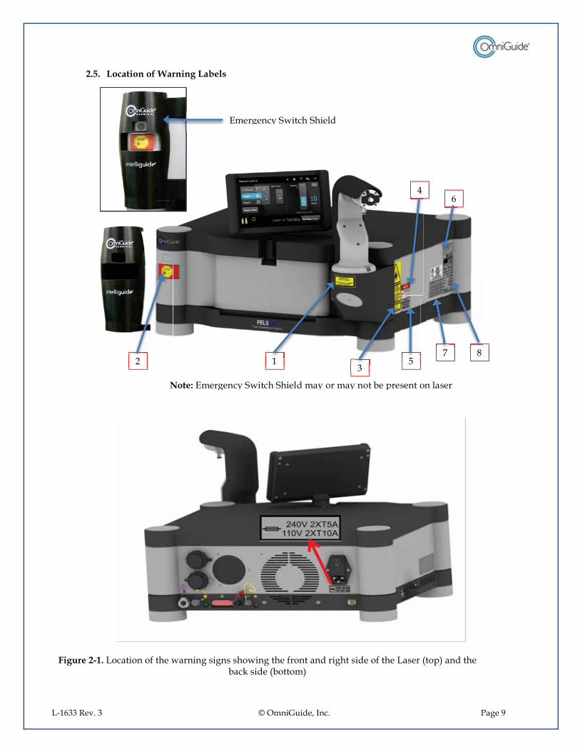
2.5.� Location of Warning Labels
Figure 2-1. Location of the warning signs showing the front and right side of the Laser (top) and the back side (bottom)
6 4
3 5
8 7 1 2 1
Note: Emergency Switch Shield may or may not be present on laser
Emergency Switch Shield

L-1633 Rev. 3 © OmniGuide, Inc. Page 10
1.� Warning Aperture
2.� Laser Stop
3.� Laser Warning
4.� Laser Danger
L-1633 Rev. 3 © OmniGuide, Inc. Page 11
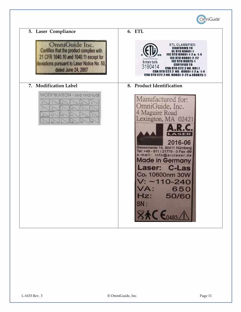
5.� Laser Compliance
6.� ETL
7.� Modification Label
8.� Product Identification
L-1633 Rev. 3 © OmniGuide, Inc. Page 12
WARNINGS 3.1.� Warnings for Laser Surgical Procedures
The FELS-25A is a Class IV Laser device that produces invisible beams of high-energy infrared radiation. Improper use could result in serious personal injury. Proper electrical and Laser safety training and strict observation of all safety precautions as specified in the Laser Instructions for Use or Operations Manual are required to operate the device and/or provide its maintenance. Before endoscopic instruments and accessories from different manufacturers are employed in a procedure, the user must verify compatibility with the OmniGuide System. If in doubt, contact OmniGuide for assistance. Laser surgical procedures should be performed only by individuals adequately trained and familiar with such surgical techniques. Consult medical literature regarding techniques, complications, and hazards prior to performing these procedures. All personnel in the immediate area of Laser use must wear eye protection specifically rated for CO2 Lasers. Failure to do so may result in serious and permanent damage to the eyes. The Laser should be activated only when the Laser treatment site is clearly observable and the fiber tip is directed at it. A fire extinguisher must be available in the operating room when the Laser is being utilized. Saline solution or water should also be readily available. Flammable prep solutions (e.g. alcohol-based prep solutions) must not be used during Laser procedures. Follow established protocols for laser surgery to minimize the risk of airway fires. A smoke evacuation system must be utilized to remove surgical plume. With most fiber assemblies, pressurized gas exits the fiber tip during the Laser procedure and may cause venous gas embolism. To reduce the risk of embolism, do not bring the tip into contact with blood vessels or vascular tissue. The gas pressure delivered to the system should not exceed the pressures listed on the insert provided with each fiber. For airway cases, the fiber should not be used below the carina. See fiber IFU for additional fiber-specific warnings. The pressurized gas exiting the fiber’s tip during the Laser procedure may cause temporary inflation and separation of sub-mucosal flaps or mild emphysema under superficial layers of tissue. Only use medical-grade Helium gas. Do not retract, probe, or manipulate tissue with the distal-end tip of the OmniGuide fiber. Do not use excessive force while handling the OmniGuide fiber inside an endoscopic handpiece. The use of excessive force could potentially lead to fiber breakage or distal-end tip detachment. The use of high Laser power along with extensive bending of the fiber may result in gas temperatures exceeding 60oC, which can cause thermal damage to healthy tissue. Always use the minimum Laser power possible for a given procedure, and minimize the amount of bending of the fiber. Do not submerge any portion of the FELS-25A Laser/Adapter in fluid. For sterile procedures, the use of the OmniGuide Gas Filter Unit (cat# ACC-GFU-100) is required. There is a possibility that the OmniGuide fiber will fail to transmit light during the course of a surgical procedure. Therefore, it is recommended that you have at least two fiber assemblies available prior to starting a surgical procedure using the OmniGuide Laser System.
L-1633 Rev. 3 © OmniGuide, Inc. Page 13
The distal-end of the OmniGuide fiber should not touch tissue. 3.2.� Warnings specific to compressed Gas
(Disclaimer: The supply of the gas per OmniGuide specifications, the gas delivery system, and the gas supply operation and maintenance procedures, including the observation of compressed gas safety precautions, are the responsibility of the healthcare-providing facility. Refer to general safety regulations for handling of compressed gases.)
If gas is being supplied to the Adapter via a compressed gas tank, review the proper procedures for handling of compressed gases before connecting the Adapter to the gas tank. Only personnel trained in compressed gas safety procedures should be allowed to connect the adapter to a compressed gas tank. Using pressurized gas during some endoscopic procedures (e.g. gastrointestinal, gynecological, etc.) could lead to over-insufflations and the danger of tissue perforation. An approved system for pressure monitoring and gas evacuation, chosen by a physician, is required to prevent over-insufflations and ensure patient safety. Use of insufflators or other approved gas evacuation devices that are equipped with a sensor for internal pressure and a pressure relief valve are recommended. Refer to the manufacturer’s instructions for equipment set up and detailed instructions. For sterile cases where Gas Filter Unit is used, never exceed the maximum gas pressure rated for the Gas Filter Unit. Always monitor the vital signs of the patient for symptoms of gas embolism Always monitor patient’s blood oxygen level. Before the start of a medical procedure using the OmniGuide Adapter and fiber, verify that the gas delivered to the system is of the proper type and pressure for the fiber being used. This information can be found on the insert provided with each fiber.
3.3.� Sterility Warnings
The OmniGuide fiber is supplied sterile. The method of sterilization is radiation. Do not use the product if the package is damaged, opened, or if sterility is compromised. The product is sold sterile for single use. Reuse poses risk of infection. Wear sterile gloves and observe proper surgical aseptic technique while handling the sterile fiber. Do not use an OmniGuide Adapter in a sterile procedure without the Gas Filter Unit (cat# ACC-GFU-100).
CAUTIONS
4.1.� Cautions for Laser Surgical Procedures Physicians performing Laser procedures should be trained and compliant with their relevant health care facility requirements in: o� Laser safety o� Clinical use of CO2 Lasers
L-1633 Rev. 3 © OmniGuide, Inc. Page 14
o� The use of the OmniGuide System
Build up of tissue or tissue debris on the distal-end tip of the OmniGuide fibers or handpiece can result in overheating of the device. If build-up/contamination occurs during use, clean the tip by dipping into saline solution. Refer to OmniGuide fiber IFUs for specific instructions on how to clean fiber tips during surgical procedures. Replace the fiber if performance does not improve. The OmniGuide fiber is a single use device. Reuse of fiber voids all warranties of sterility and is prohibited. Do not bend the OmniGuide fiber to a radius less than the minimum radius and maximum angle specified for the fiber (typically 3cm, 30 degree). Bending the fiber below this limit may cause fiber failure. Refer to fiber IFUs for more instructions on fiber usage. To assure the proper functioning of the device, FELS-25A must be serviced be performed by an OmniGuide authorized representative. After a surgical procedure, visibly inspect the integrity of the OmniGuide Fiber. In particular, verify that no portion of the fiber is missing or detached. Excessive bending of OmniGuide fiber will lower its output power. Please consult fiber IFUs for the minimum allowable bending radius and angle of the fiber. Do not kink or pinch the Fiber.
The OmniGuide System is not compatible with optical accessories such as scanners.
4.2.� Reflected energy protection Avoid reflective metals near the laser beam. Clinician and patient must use appropriate eye and skin protection.
4.3.� Fire Protection
Drape the surgical field with materials designed for use with Lasers. The surgical drape must be flame retardant. Keep combustible materials away from the area of Laser use. Take appropriate measures to prevent the possibility of a fire associated with anesthesia such as use of a laser safe tracheotomy tube at the 10.6 micron wavelength, and maintaining oxygen levels at 30% or less of the anesthetic mixture while firing.
4.4.� Eye protection Everyone in the Laser area must wear eye protection appropriate for CO2 Lasers. Use special precautions when working around eyes. Do not look directly at the Laser beam, even when wearing eye protection.
4.5.� Tissue protection Start with low power and increase power gradually to achieve desired effect. Use the shortest exposure time for the desired result.
L-1633 Rev. 3 © OmniGuide, Inc. Page 15
Exposure of charred tissue to the laser radiation can heat and injure underlying tissue layer. The clinician’s skin should be protected from exposure and the patient’s skin should be protected from overexposure to Laser radiation. The CO2 laser is approved for soft tissue only and can cause thermal damage to bones and teeth. Protect them from exposure to laser radiation as necessary. 4.6.� Smoke Control Smoke from the procedure could contain biologically hazardous materials and has to be evacuated. Run smoke evacuator for 30 seconds after lasing stops. The clinician should wear a mask. Refer also to the Cautions section of your Laser Manual and to Laser Labeling for additional precautions.
PRODUCT DESCRIPTION
In this section the specifications and characteristics of the FELS-25A system will be discussed. Characteristics to be discussed include mechanical, thermal, electric and the laser system user interfaces. Also discussed are environmental requirements and limitations.
5.1.� Fiber Enabled Laser
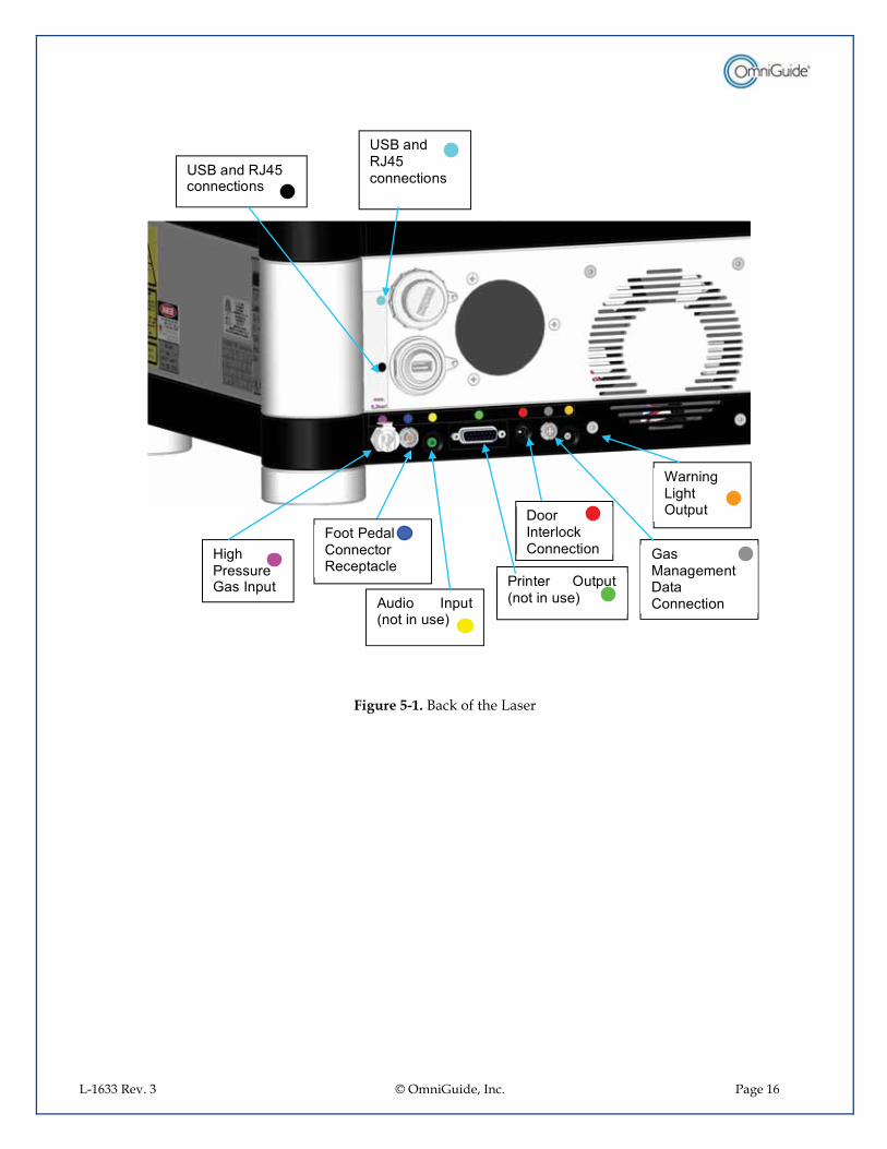
The Laser is a class IV sealed, RF excited CO2 Laser capable of producing CW or pulsed laser radiation at 10.6 µm wavelength. The laser is operated via a foot pedal to allow laser radiation only when required. The back and front of the Laser are shown in Figure 5-1 and Figure 5-2 respectively.
L-1633 Rev. 3 © OmniGuide, Inc. Page 16
Figure 5-1. Back of the Laser
�������� ������ ��������
������������������� ��
������ ���� ������ �� ����
����������������� ������ ��
����������������������
� � � ������� ���������
! ���� ����� ����� ��"����������
#$%��� �"&'(�� ������ ���
#$%��� �"&'(�� ������ ���
L-1633 Rev. 3 © OmniGuide, Inc. Page 17
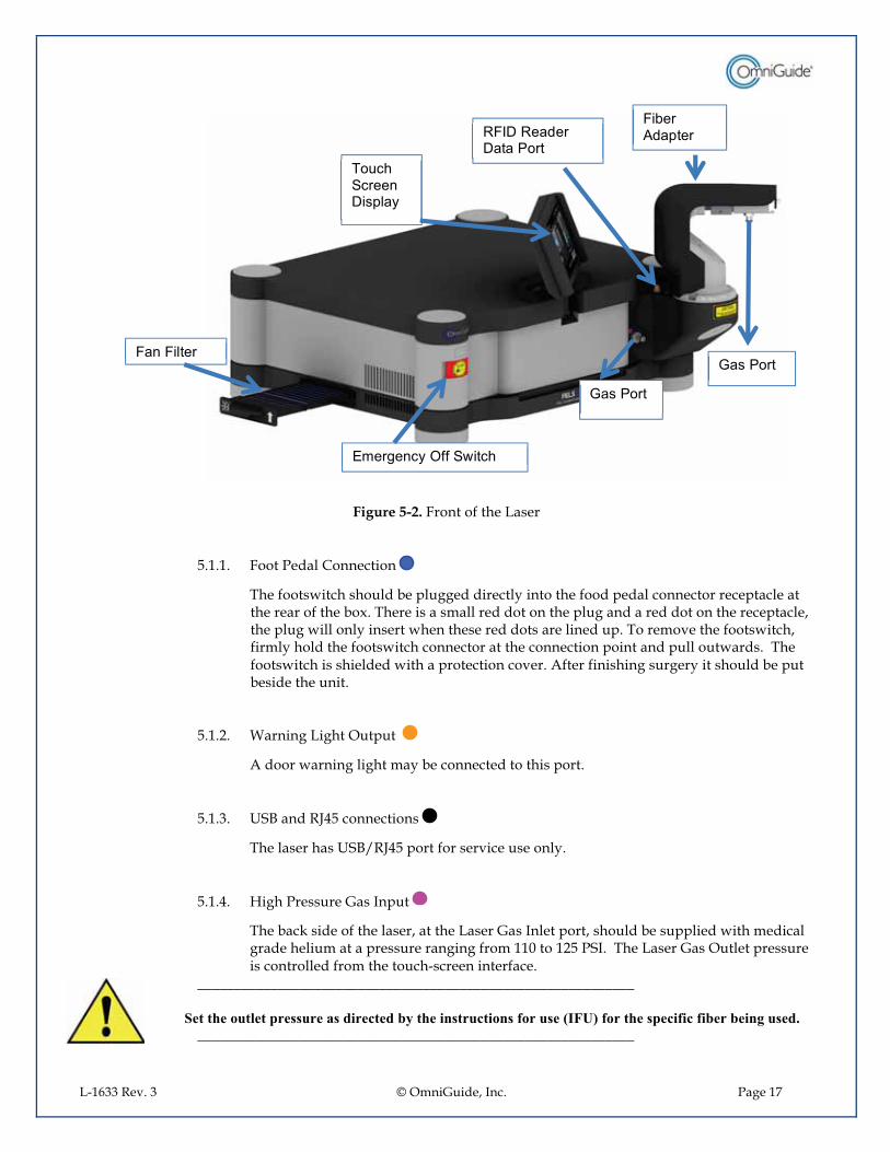
Figure 5-2. Front of the Laser
5.1.1.� Foot Pedal Connection
The footswitch should be plugged directly into the food pedal connector receptacle at the rear of the box. There is a small red dot on the plug and a red dot on the receptacle, the plug will only insert when these red dots are lined up. To remove the footswitch, firmly hold the footswitch connector at the connection point and pull outwards. The footswitch is shielded with a protection cover. After finishing surgery it should be put beside the unit.
5.1.2.� Warning Light Output
A door warning light may be connected to this port.
5.1.3.� USB and RJ45 connections
The laser has USB/RJ45 port for service use only.
5.1.4.� High Pressure Gas Input
The back side of the laser, at the Laser Gas Inlet port, should be supplied with medical grade helium at a pressure ranging from 110 to 125 PSI. The Laser Gas Outlet pressure is controlled from the touch-screen interface.
____________________________________________________________ Set the outlet pressure as directed by the instructions for use (IFU) for the specific fiber being used. ____________________________________________________________
) ���$������������*�
!�+���� ������
!���!������
����� ���
����� ���
"!���"�� ��������� ���
,�������*�--�$.�����
L-1633 Rev. 3 © OmniGuide, Inc. Page 18
5.1.5.� Gas Management Data Connection
If helium gas supplied from helium gas tanks on the laser system cart, the system has the ability to display the amount of gas available in the gas tanks on the laser touch screen. The gas management data connectors on the back of the laser and on the gas management system have to be connected by a gas management data cable supplied with the system (P/N 1-0142-014-00-01).
5.1.6.� Door Interlock
The door interlock connection allows the use of the door interlock safety feature, as may be required at your health care facility. If the door to the room where the laser is being used is opened, this feature will automatically disable operation of the laser. If door interlock operation is not required, a door interlock plug, (supplied with the system, P/N 1-0205-007-01-03), can be plugged into the door interlock connection at the back of the laser to defeat the interlock and allow operation of the laser. The door interlock feature is implemented through the laser software.
5.1.7.� RFID Antenna
RFID antenna is built into the fiber adapter and is a component of the system RFID functionality that allows the laser system to recognize specific Omniguide fiber and adjust accordingly the default settings and settings limits for the power and gas pressure. The specific fiber type is indicated on the laser touch screen.
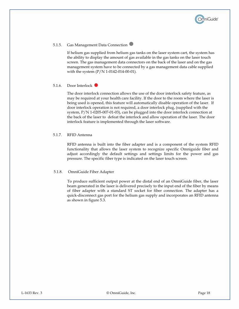
5.1.8.� OmniGuide Fiber Adapter
To produce sufficient output power at the distal end of an OmniGuide fiber, the laser beam generated in the laser is delivered precisely to the input end of the fiber by means of fiber adapter with a standard ST socket for fiber connection. The adapter has a quick-disconnect gas port for the helium gas supply and incorporates an RFID antenna as shown in figure 5.3.
L-1633 Rev. 3 © OmniGuide, Inc. Page 19
Figure 5-3. Close up of socket of the fiber adapter, where the OmniGuide fiber is connected. Note the groove in the fiber connection socket. It should be aligned with the arrow/key on the connector of the fiber for the fiber to properly connect.
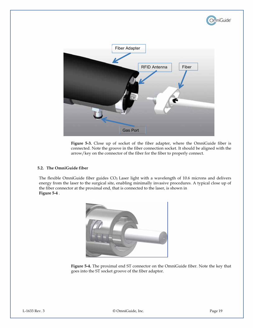
5.2.� The OmniGuide fiber
The flexible OmniGuide fiber guides CO2 Laser light with a wavelength of 10.6 microns and delivers energy from the laser to the surgical site, enabling minimally invasive procedures. A typical close up of the fiber connector at the proximal end, that is connected to the laser, is shown in Figure 5-4 .
Figure 5-4. The proximal end ST connector on the OmniGuide fiber. Note the key that goes into the ST socket groove of the fiber adaptor.
!�+���� ������
!�+���
����� ���
"!�����������
L-1633 Rev. 3 © OmniGuide, Inc. Page 20
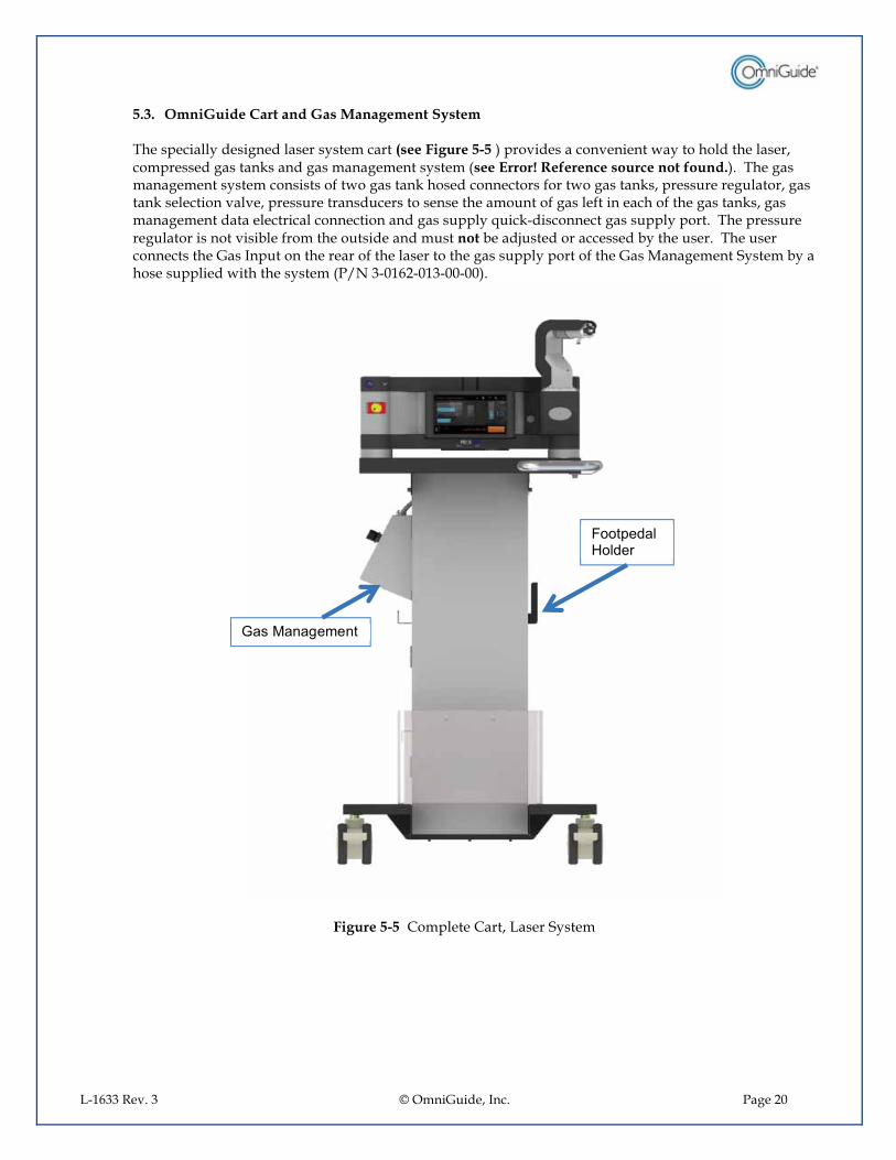
5.3.� OmniGuide Cart and Gas Management System The specially designed laser system cart (see Figure 5-5 ) provides a convenient way to hold the laser, compressed gas tanks and gas management system (see Error! Reference source not found.). The gas management system consists of two gas tank hosed connectors for two gas tanks, pressure regulator, gas tank selection valve, pressure transducers to sense the amount of gas left in each of the gas tanks, gas management data electrical connection and gas supply quick-disconnect gas supply port. The pressure regulator is not visible from the outside and must not be adjusted or accessed by the user. The user connects the Gas Input on the rear of the laser to the gas supply port of the Gas Management System by a hose supplied with the system (P/N 3-0162-013-00-00).
Figure 5-5 Complete Cart, Laser System
���������������
! ��� ���� � ���

L-1633 Rev. 3 © OmniGuide, Inc. Page 21
Figure 5-6 Gas Management System
____________________________________________________________
Prior to starting the surgical procedure make sure that the gas tank valves are open. ____________________________________________________________
____________________________________________________________
Prior to replacing the compressed tank make sure that the gas tank valve is closed. ____________________________________________________________
����)����$����� ��/��0��
����� ���
����� ���
���������� ���
��������������������� ������ ��
L-1633 Rev. 3 © OmniGuide, Inc. Page 22
____________________________________________________________
Refer to OmniGuide fiber IFUs for instructions on choosing appropriate gas pressure settings. ______________________________________________________
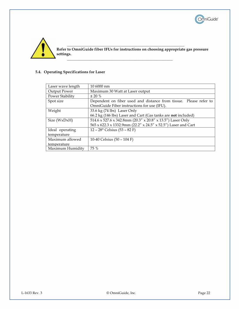
5.4.� Operating Specifications for Laser
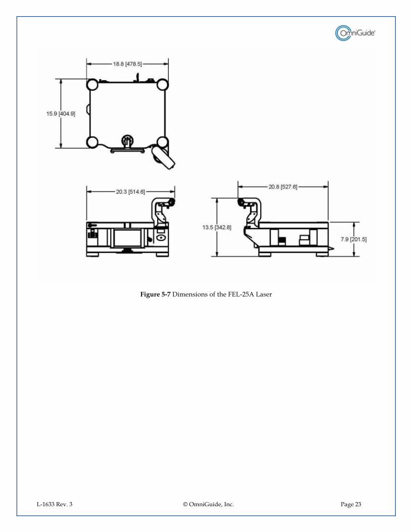
Laser wave length 10 6000 nm Output Power Maximum 30 Watt at Laser output Power Stability ± 20 % Spot size Dependent on fiber used and distance from tissue. Please refer to
OmniGuide Fiber instructions for use (IFU). Weight 33.6 kg (74 lbs) Laser Only
66.2 kg (146 lbs) Laser and Cart (Gas tanks are not included) Size (WxDxH) 514.6 x 527.6 x 342.8mm (20.3” x 20.8” x 13.5”) Laser Only
565 x 622.3 x 1332.9mm (22.2” x 24.5” x 52.5”) Laser and Cart Ideal operating temperature
12 – 28° Celsius (53 – 82 F)
Maximum allowed temperature
10-40 Celsius (50 – 104 F)
Maximum Humidity 75 %
L-1633 Rev. 3 © OmniGuide, Inc. Page 23
Figure 5-7 Dimensions of the FEL-25A Laser

L-1633 Rev. 3 © OmniGuide, Inc. Page 24
Figure 5-8 Dimensions for the Fiber Enabled Laser on OG designed Cart

L-1633 Rev. 3 © OmniGuide, Inc. Page 25
SAFETY
6.1.� Laser Safety Requirements This Laser does conform to the United States or Foreign Government requirements for Laser safety. These Laser safety requirements are contained in 21 CFR, 1040.10 and 1040.11 and are administered by the FDA Center for Devices and Radiological Health. A Laser Report, detailing how the Laser product complies with the federal laws is required to be submitted to FDA on an annual basis. The form of this report is covered in a pamphlet entitled: Guide for Preparing Product Reports for Lasers and Products Containing Lasers, Sept. 1995:
U.S. Department of Health and Human Services Public Health Service Food and Drug Administration Center for Devices and Radiological Health Division of Small Manufactures Assistance Rockville, MD 20857 Web Site: http://www.fda.gov/cdhr
For jurisdictions outside of the United States, it is the responsibility of the buyer of this Laser device to ensure that it meets the local Laser safety regulations.
6.2.� Optical Safety
The FELS-25A Laser has undergone extensive testing to ensure that, with proper usage, it is a safe and reliable device. Laser light, because of its special properties, poses safety hazards not associated with light from other sources. The light from the FELS-25A is invisible to the naked eye. The safe use of Laser requires that all operators be properly trained and the proper use of PPE be used in the operation of this device.
____________________________________________________________
Direct eye contact with the output beam from the Laser will cause serious damage and may cause blindness. CO2 Laser Radiation is invisible.
____________________________________________________________
All personnel in the Laser Treatment Control Area, LTCA or anyone who may enter the LTCA should be informed that a Laser is in operation. All personnel within the Nominal Hazard Zone (NHZ) must wear Laser safety glasses (OD > 5), which protect against the wavelength (10.6 microns) in use. The NHZ (Nominal Hazard Zone) is 2.4m from the exit of the fiber. For laparoscopic cases, the NHZ is isolated within the patient. The use of laser safety glasses is up to the discretion of the facility.
_____________________________________________________________
L-1633 Rev. 3 © OmniGuide, Inc. Page 26
Exercise caution to protect against reflections off shiny and mirror-like surfaces. Reflections of the FELS-25A Laser light are invisible to the naked eye.
______________________________________________________________
Eye, skin and fire safety is a great concern when using a high-power, class IV Laser such as the FELS-25A. There is potential for secondary beams present at various angles near the incident radiation site. While weaker than the main beam, such beams may still be sufficiently intense to cause eye damage and skin burns. Laser beams are also powerful enough to burn skin, clothing or paint. They can ignite volatile substances such as alcohol, gasoline, ether and other volatile solvents and can damage the light-sensitive elements in video cameras, photo multipliers and photo diodes.
OmniGuide provides the following recommendations to promote the safe use of the FELS-25A. Operators are advised to adhere to these recommendations and employ sound Laser safety practices at all times.
•� Always follow the safe Laser usage guidelines, law or regulations relevant to the
country, state, province etc, when you are operating or installing the Laser.
•� Use protective eye wear when operating the Laser and guard against inadvertent exposure of skin or clothing to the laser radiation. Select eye wear which is suitable for use with the wavelengths and radiation intensity that the Laser emits – 10.6 µm.
•� Never look directly into the Laser output port when the power is on.
•� Post warning signs to alert personal of the use of a Laser. When operating the
Laser, limit access to the area to individuals who are trained in Laser safety.
•� Do not use the Laser in the presence of flammable, explosives, or volatile solvents such as alcohol, gasoline or ether.
For additional information on Laser safety, refer to the following publications:
•� ANSI Z136.1, ANSI Z-136.3 and IEC 60825 •� Performance Standard for Laser Products. FDA, CFR 21 1040.10 and 1040.11 •� CAN/CSA-Z386-08: Laser Safety in Health Care Facilities
6.3.� Electrical Safety The laser is ETL complaint and conforms to the following: •� UL STD 60601-1 •� IEC STD 60601-1-2 & -1-4 •� IEC STD 60601-2-22 •� IEC STD 60825-1 •� Certified to: •� CSA STD C22.2 NO. 601.1 •� CSA STD C22.2 NO. 60601-1-2 & -1-4

L-1633 Rev. 3 © OmniGuide, Inc. Page 27
•� CSA STD C22.2 NO. 60601-2-22 & E60825-1
6.3.1.�Door Interlock The system has the capability to interlock the doors to the room where the Laser is operated. The interlock connection can be found at the rear of the laser (red colored rear input).
.
6.4.� Compliance to Standards Relevant to CE-Mark
The FELS-25A Laser does meet all the applicable standards of the CE-Mark. Please see section 17 for more details.
TRANSPORTATION AND STORAGE
If the system has been transported or stored at temperatures below 10°C (50 F), unpack the device and leave it at normal room temperatures at least for half a day so that the laser reaches room temperature.
For extended storage, the FELS-25A is should be stored in dry environment at normal room temperatures.
store at temperatures: 10°C to 40°C (50°F to 104°F)
pressure: 860 hPa to 1060 hPa (25 in Hg to 31.4 in Hg)
Indicates upper side. Keep upright.
fragile – handle with care.
keep dry
1�2� 34
�5��� 34
������� ��������
L-1633 Rev. 3 © OmniGuide, Inc. Page 28
UNPACKING AND INSPECTION
Before unpacking the Laser inspect the shipping container carefully for evidence of rough handling and note any damage. Inform the shipping carrier and OmniGuide or the distributor of any evidence of damage in shipment. If there is any discrepancy noted, inform you distributor or OmniGuide directly. PLEASE NOTE THAT THE CART WILL ARRIVE IN SEPARATE SHIPPING CONTAINER. IT MUST BE ASSEMBLED BEFORE UNPACKING THE LASER.
8.1.� List of items in the box - Fiber Enabled Laser - Power cord - Foot pedal - FELS-25A Fiber Enabled CO2 Laser System Instructions for Use. - Gas hoses - OR Staff training and reference materials - Laser safety signage
If any items are missing, immediately report this to OmniGuide or the representative in your country. Report exactly the items missing and verify whether the Laser can be installed or the items missing will not allow you to install and operate the Laser. If you need to ship the Laser back to OmniGuide, you MUST ship it in the OmniGuide shipping container and packing material. If the Laser is not packed properly and damage occurs during shipment, the customer will incur all charges for the repair of broken or damaged parts.
8.2.� Safety Issues in Cart Assembly and Laser Setup
Setup of the FELS-25A must comply with all applicable electrical safety and Laser safety laws and regulations in the country the Laser is installed. Review all the regulations which exist in your country. Some information regarding safety based on international laws like in the EC (EN) or US (FDA) regulations is listed below. Do not connect the Laser power cable to wall outlets without a proper ground. Do not connect other instruments to the same wall outlet where the Laser is connected. Check the fuse for the wall outlet with the rating given in this manual (The fuse installed is rated for a specific voltage used). Do not use power cables other than those supplied with the instrument. If the connection to the main power socket is different than the cable supplied, contact your local electric supply office for guidelines on the power cable to be used with medical equipment.
L-1633 Rev. 3 © OmniGuide, Inc. Page 29
Do not setup the unit close to any flammable material. During use of the Laser air ventilation from the bottom of the instrument is used to cool the Laser and associated electronics. Never block this air ventilation. Be sure the Laser is properly secured to avoid the possibility of the Laser moving during treatment, thus creating a hazardous condition. Do not store any high reflecting material close to the Laser beam output to avoid any unwanted reflections. The Laser beam is invisible and can create skin burning if not properly directed. All people inside the room including the patient have to wear protective eyewear to avoid unwanted Laser light directly, scattered or reflected entering the eye. Do not fire the Laser until the surgeon and the patient are positioned correctly. The entrance to the room has to be clearly marked that a Laser is in use. During surgery the room should be interlocked in such a way that no one can enter the room without protective eye wear. Only authorized and properly trained personnel are allowed to operate the Laser. The Laser must be turned off at all other times to prevent unauthorized usage.
FACILITIES REQUIREMENT The dimensions of the Laser are given in Figure 5-7 and the dimensions of the entire FELS-25A system with a cart with gas handling capability are given in Figure 5-8. If the cart is not available with the Laser the following information is important for safe use.
The Laser should be placed on a table with four feet being in contact with the table or cart. Make sure the Laser is sitting securely on the table or cart. Do not stress or bend the housing of the Laser to avoid any misalignment of the laser beam. The fiber adapter must be protected to ensure it is safe from inadvertent jarring that could cause laser beam misalignment. Do not block the entrance of the air intake, which is the space between the feet and the housing. Do not install the Laser on cartons or material that are flammable. Since the main switch is at the back of the instrument do not move the Laser all the way against the wall.
9.1.� Air cooling Requirements Total heat dissipation of the Laser and the electronics is about 680 Watts. The Laser head typically dissipates 325 Watts at full power from its base surface. The low voltage electronics and the power supply dissipate approximately 355 Watts.
The Laser must be adequately cooled through the bottom of the machine via forced air going through the protective filter. No cooling or blocking of the air going through the Laser will result in a misalignment of the
L-1633 Rev. 3 © OmniGuide, Inc. Page 30
Laser head and consequently a drop of power. Operating with dust, water or dirt in the environment around the Laser or without the filter could result in damage to the Laser.
__________________________________________________ Never operate the Laser without the air filter, do not use any other filter than the one provided by OmniGuide.
____________________________________________________________
9.2.� Electrical Power Connection
The FELS-25A requires AC voltage 90-260 Volts , 50/60 Hz.
The mains cable should be rated above 12A continuous AC current Use main cable supplied with the system. Make sure that the mains ground connection is made. . The mains cable is connected to the rear of the Laser into the socket with the following characteristics:
Input voltage: 90-260 V, 50/ 60 Hertz Ground connection required Leakage current trip: less 300 µA Input current fuses 90 V / 12A, 115 V / 10A, 260 V / 5A The mains socket should be properly fixed to the wall; it is not allowed to use an extension cable between the Laser and the wall outlet.
9.2.1.� Fuse Ratings for the Laser Different input voltages require a different fuse rating. 230 V 5A 115 V 10A 90 V 12A
9.3.� Compressed Gas Requirement
The OmniGuide Laser system is designed to be used with medical-grade Helium gas, delivered to the fiber at a pressure that depends on the type of fiber and the application. Please see fiber IFU for details. The gas flow is established by connecting the gas hose (supplied with the system) to a Helium source (provided by the user). The gas hose has a 1/8” quick-disconnect fitting to facilitate this attachment. The helium source is then connected to the gas port at the back of the laser. The gas outlet on the front of the laser has a 1/8 “ quick disconnect port. The gas hose supplied with the system connects the gas outlet at the front of the laser to the fiber adapter. A Gas Filter Unit (P/N ACC-GFU-100-1) between the gas hose and the adapter is required for sterile procedures.
9.4.� Door Interlock
The Laser is installed in a room which is clearly marked as Laser room and could be interlocked through the Laser console. To allow the door to be wired into the Laser, the Laser console has an interlock connector at the rear of the housing.
L-1633 Rev. 3 © OmniGuide, Inc. Page 31
The door interlock is a switch in normal open condition. When the door is closed and the laser can be operated, the switch needs to be in closed condition. At this time the interlock at the Laser console is closed and the Laser can be started. If the door is opened during laser operation, the laser switches off.
________________________________________________________________ When door interlock is not mandated, a connector needs to be in place to defeat the door interlock in order for the laser to be started. A door interlock plug has to be used to allow laser operation (P/N 1-0205-007-01-03).
_________________________________________________________________
9.5.� Foot Pedal Connector
The foot pedal is directly attached to the back of the Laser (Figure 5-1). The foot pedal can be removed by pulling the connector from the rear of the laser. The foot pedal is shielded with a protection cover.
�SYSTEM OPERATION
10.1.�Switch on Laser System
The Laser console has to be properly seated on a solid base to avoid any movement of the console. The mains power cord connector is firmly placed into the wall outlet. The interlock connector is in place and firmly attached. The foot pedal is in comfortable position.
10.2.�Main Power Switch
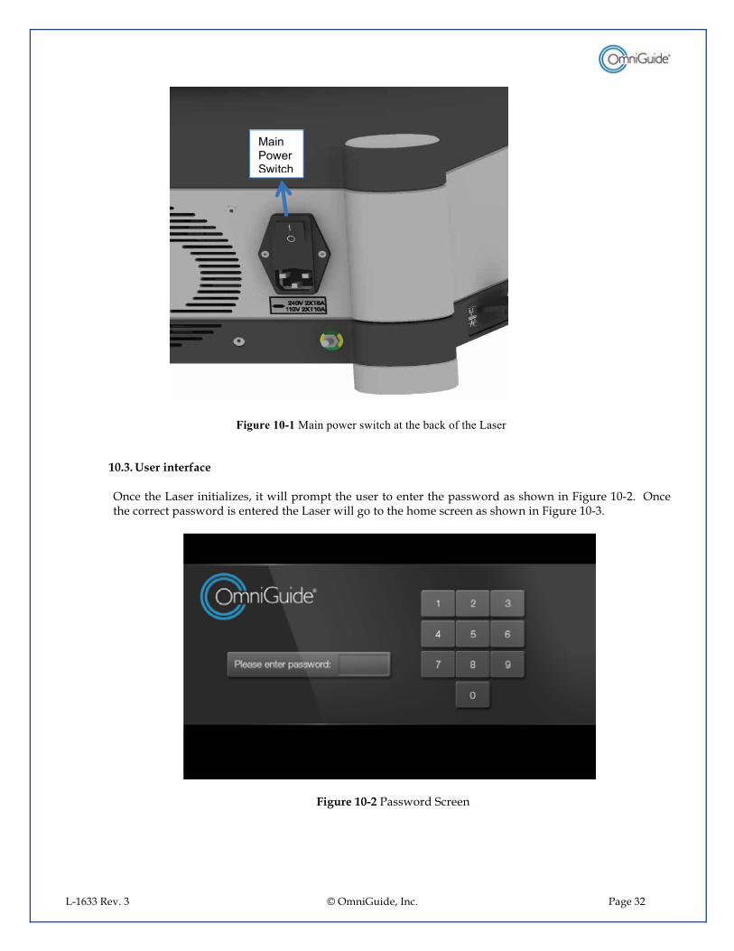
The main power switch is located at the back of the Laser console as shown in Figure 10-1. Press the switch into the “ON” position. When the Laser has been initialized it will go through a series of system-checks. This allows the internal parameters to be checked and verify the system is running according to specifications. This routine takes about 2 minutes, and when complete the display will change to the pin code screen (see Error! Reference source not found.).
L-1633 Rev. 3 © OmniGuide, Inc. Page 32
Figure 10-1 Main power switch at the back of the Laser
10.3.�User interface Once the Laser initializes, it will prompt the user to enter the password as shown in Figure 10-2. Once the correct password is entered the Laser will go to the home screen as shown in Figure 10-3.
Figure 10-2 Password Screen
������ .���$.����
L-1633 Rev. 3 © OmniGuide, Inc. Page 33
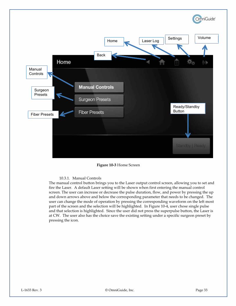
Figure 10-3 Home Screen
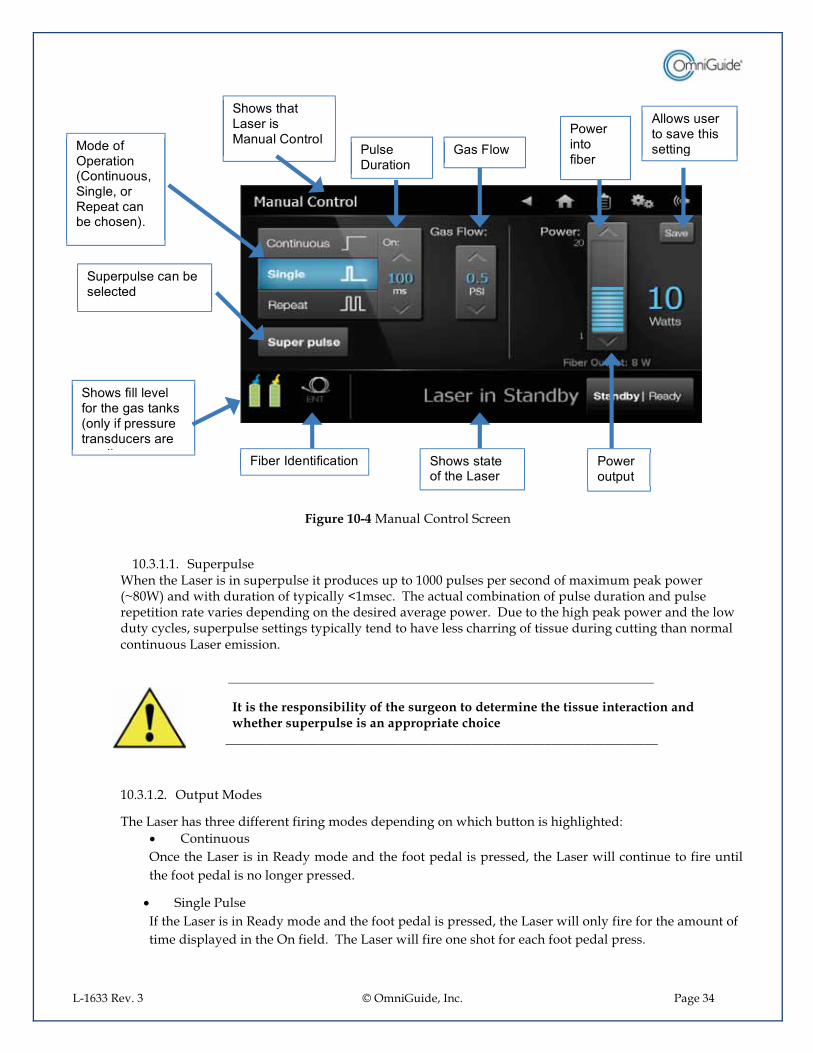
10.3.1.� Manual Controls The manual control button brings you to the Laser output control screen, allowing you to set and fire the Laser. A default Laser setting will be shown when first entering the manual control screen. The user can increase or decrease the pulse duration, flow, and power by pressing the up and down arrows above and below the corresponding parameter that needs to be changed. The user can change the mode of operation by pressing the corresponding waveform on the left most part of the screen and the selection will be highlighted. In Figure 10-4, user chose single pulse and that selection is highlighted. Since the user did not press the superpulse button, the Laser is at CW. The user also has the choice save the existing setting under a specific surgeon preset by pressing the icon.
������� ��� ���
$��� ����������
!�+�����������
%����
� ��� ������� �� $�������� / ����
"�� *6$��� +*�%�� �
L-1633 Rev. 3 © OmniGuide, Inc. Page 34
Figure 10-4 Manual Control Screen
10.3.1.1.� Superpulse When the Laser is in superpulse it produces up to 1000 pulses per second of maximum peak power (~80W) and with duration of typically <1msec. The actual combination of pulse duration and pulse repetition rate varies depending on the desired average power. Due to the high peak power and the low duty cycles, superpulse settings typically tend to have less charring of tissue during cutting than normal continuous Laser emission.
________________________________________________________________ It is the responsibility of the surgeon to determine the tissue interaction and whether superpulse is an appropriate choice
_________________________________________________________________
10.3.1.2.� Output Modes
The Laser has three different firing modes depending on which button is highlighted: •� Continuous Once the Laser is in Ready mode and the foot pedal is pressed, the Laser will continue to fire until the foot pedal is no longer pressed.
•� Single Pulse If the Laser is in Ready mode and the foot pedal is pressed, the Laser will only fire for the amount of time displayed in the On field. The Laser will fire one shot for each foot pedal press.
� �� -������� ���� ���� ���$������� ��"����������+���� ����7��
$� .�������� -�����������
$������������+��������� �
$� .��-������0���- ����������������� ��*��-�������������� ���������
� !�+���� ����-����� �
$� .����������������������� ��� ���
��� .������� ���0���������������������
����� ������!� .��
� .������ �-�+���
� .��� ����

L-1633 Rev. 3 © OmniGuide, Inc. Page 35
•� Repeat Pulse If the Laser is in Ready mode and the foot pedal is pressed, the Laser will switch between firing and not firing, with each portion lasting for the amount of time displayed in the On field. This will be repeated for as long as the foot pedal is pressed.
10.3.1.3.� On Time
This field changes the time values required for Single Pulse and Repeat Pulse discussed above. If Continuous is chosen, this field is disabled.
10.3.1.4.�Gas Flow
User controls the flow in PSI during READY mode within the parameter space allowed by the RFID tag on the fiber. If the user adjusts the flow during STANDBY that flow will take effect when the user goes to READY. In STANDBY the flow will automatically be reduced to the low flow preset (set in the advanced settings) or will remain the same as in READY if the flow at READY was set to lower than the low flow preset.
10.3.1.5.� Power Setting
This field is where the power output of the Laser is set. The small number directly below the “Power” text is the maximum power that is allowed at that time. The set power is displayed as the amount of blue bars shown, as well as the large blue letters to the right of the bars. The up and down arrow control the power output set point.
10.3.1.6.� Fiber Output
When Laser energy is fired into a fiber optic, a certain amount of that energy is lost and is not transmitted to the patient. Each fiber will lose a different amount of energy depending on manufacturing variations. The fiber output is the estimated amount of power output that passes through the fiber and is exposed to the patient.
10.3.1.7.� Ready / Standby
The ready / standby button controls whether the Laser will fire when the foot pedal is pressed. Depending on what the gas flow is set to, this button may also control whether the system is flowing the displayed value, or a lower value while in Standby. The status bar to the left of the button displays what state the Laser is currently in. It has three options: •� Laser in Standby
The Laser will not fire if the foot pedal is pressed. Gas flow is set to minimal or the last value while the Laser was in READY prior to going to STANDBY.
•� Laser in Ready
The Laser will fire if the foot pedal is pressed. Gas flow is set to the displayed value. •� Laser is Firing
The foot pedal is currently pressed and the Laser is firing. Gas flow is set to the displayed value. The status will change back to “Laser in Ready” once the foot pedal is not longer pressed.
L-1633 Rev. 3 © OmniGuide, Inc. Page 36
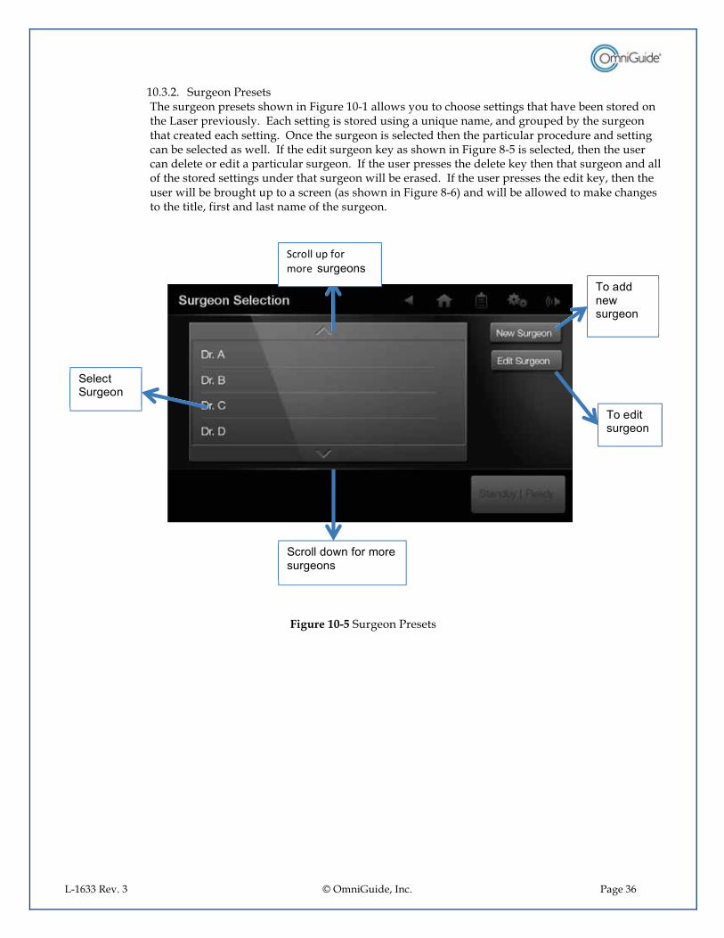
10.3.2.� Surgeon Presets The surgeon presets shown in Figure 10-1 allows you to choose settings that have been stored on the Laser previously. Each setting is stored using a unique name, and grouped by the surgeon that created each setting. Once the surgeon is selected then the particular procedure and setting can be selected as well. If the edit surgeon key as shown in Figure 8-5 is selected, then the user can delete or edit a particular surgeon. If the user presses the delete key then that surgeon and all of the stored settings under that surgeon will be erased. If the user presses the edit key, then the user will be brought up to a screen (as shown in Figure 8-6) and will be allowed to make changes to the title, first and last name of the surgeon.
Figure 10-5 Surgeon Presets
$������$��� ��
) �� ������� ��
) �� ���.����� ��
��������������������� ��
$�� ��� .��- ��� ������� ���

L-1633 Rev. 3 © OmniGuide, Inc. Page 37
Figure 10-6 Edit or Delete Surgeons
Figure 10-7 Surgeon Presets
$������$��� ��
) �� ������� �� ) � ������
���� ��
��������������������� ��
$�� ��� .��- ��� ������� ���
,8�������9, ���
$��� ��$������ ��9� ���
$������!��� �� �+��� ��� ���������-������� ������������
:�*+ ��
$�0�� ���������������������
%���������
$��-����*�
L-1633 Rev. 3 © OmniGuide, Inc. Page 38
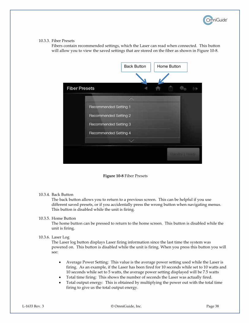
10.3.3.�Fiber Presets Fibers contain recommended settings, which the Laser can read when connected. This button will allow you to view the saved settings that are stored on the fiber as shown in Figure 10-8.
Figure 10-8 Fiber Presets
10.3.4.�Back Button The back button allows you to return to a previous screen. This can be helpful if you use different saved presets, or if you accidentally press the wrong button when navigating menus. This button is disabled while the unit is firing.
10.3.5.�Home Button The home button can be pressed to return to the home screen. This button is disabled while the unit is firing.
10.3.6.�Laser Log The Laser log button displays Laser firing information since the last time the system was powered on. This button is disabled while the unit is firing. When you press this button you will see:
•� Average Power Setting: This value is the average power setting used while the Laser is firing. As an example, if the Laser has been fired for 10 seconds while set to 10 watts and 10 seconds while set to 5 watts, the average power setting displayed will be 7.5 watts
•� Total time firing: This shows the number of seconds the Laser was actually fired. •� Total output energy: This is obtained by multiplying the power out with the total time
firing to give us the total output energy.
%����%�� �� � ���%�� ��
L-1633 Rev. 3 © OmniGuide, Inc. Page 39
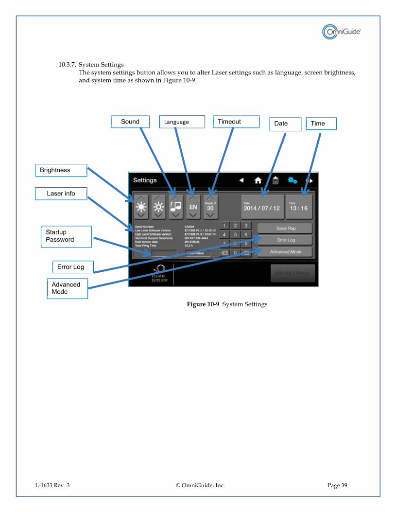
10.3.7.�System Settings The system settings button allows you to alter Laser settings such as language, screen brightness, and system time as shown in Figure 10-9.
Figure 10-9 System Settings
$ � � �������� )��� �� �����
%����������
��������- �
)����
$����������. � �
� 0���� �� ��
,�� ��� ��
L-1633 Rev. 3 © OmniGuide, Inc. Page 40
10.3.7.1.�Sound: This button sets the volume of the tone when keys are pressed and the volume of the empty tank alarm
10.3.7.2.�Language: This button cycles through the different languages provided on the system.
10.3.7.3.�Timeout If the Laser system is in Ready mode but not being used, after a certain amount of time the system will automatically revert to Standby mode. This is to ensure that the Laser is not accidentally fired if the foot pedal is pressed inadvertently. The timeout button will change this amount of time, and is shown in minutes.
10.3.7.4.� Date: This reflects the current date.
10.3.7.5.� Time: This allows the time of the system to be updated.
10.3.7.6.� Error Log: This function is used by service technicians.
10.3.7.7.� Advanced Settings: This is an advanced setting screen that is only accessible by OmniGuide personnel.
10.3.8.�Volume This button controls the volume of the firing noise.
10.3.9.�Ready/Standby Button The ready/standby button controls when the Laser will be allowed to fire if the foot pedal is pressed. This button is only active in the Laser output control screen, and is disabled for all other screens.
10.4.�OmniGuide Fiber Instructions for Use OmniGuide’s BeamPath™ flexible fiber connects to a CO2 Laser via a custom optical Adapter. The fiber has a hollow core through which CO2 Laser energy and inert gas travel. These flexible fibers can be used either with one of several surgical specific handpieces, or through an endoscope, to facilitate access to difficult to reach anatomy. The OmniGuide fiber transmits a CO2 Laser beam, along with a flowing gas, to a treatment site as directed by a physician. Please read the instructions for use (IFU) included with all fiber products to ensure proper usage.
_____________________________________________________________
If uncertain about any portion of this IFU, contact OmniGuide for assistance.
10.4.1.�Preoperative System Preparation Visually inspect the fiber adapter and verify that there is no discernible damage, that all parts are clean and there are no loose parts or loose connections. Wipe the Adapter, gas input port, and ST connection with sterile gauze and sterile saline. For sterile cases, use aseptic technique to attach the sterile Gas Filter Unit (P/N ACC-GFU-100) to the output tube.
_____________________________________________________________
L-1633 Rev. 3 © OmniGuide, Inc. Page 41
Do not use the FELS-25A system in a sterile procedure without the Omni-Guide Gas Filter Unit (P/N ACC-GFU-100).
_____________________________________________________________
10.4.2.� Gas delivery system
Verify that appropriate gas type and pressure setting are used. Refer to the fiber IFU for specific gas pressure settings. Attach gas hose to the quick connect fitting on the Adapter. For sterile cases be sure to wipe the adapter gas connection with sterile gauze and sterile saline, prior to attachment of the Gas Filter Unit.
10.5.�Ready
Once the system is put into “Ready Mode”, pressing the foot pedal activates the Laser energy output.
_____________________________________________________________________________
At this time everyone present in the operating room must be wearing appropriate protective eyewear. All entrances to operating room must be marked with Laser safety signs.
______________________________________________________
Never leave the Laser in the ready mode when not in use. __________________________________________________________________________
10.6.�System operation during surgical procedure
During the procedure, be sure to observe sterile technique. The Laser and OmniGuide Adapter are not sterile. The Adapter does not need to be sterilized, but the adapter can only be used in sterile procedures when it is accompanied by the OmniGuide Gas Filter Unit (P/N ACC-GFU-100). For sterilization protocol and setup instructions, refer to Device Setup Instructions included with the OmniGuide Gas Filter Unit. Note: The Laser may time-out and move to an idle state if left unused for the time period set. Pressing the Ready button on the Laser console will ensure that the system is ready for use. Note for OG Fiber Assemblies: Excessive heating of the fiber tip associated with light transmission failure may cause the fiber tip geometry to become distorted, preventing its removal from an endoscope or handpiece. In this case, remove the scope or handpiece with the fiber from the patient. The fiber can then be removed from the endoscope or handpiece and discarded according to Health Care Facility procedures for a bio hazardous material disposal. DO NOT REUSE THE FIBER!

L-1633 Rev. 3 © OmniGuide, Inc. Page 42
10.7.�Post-Operative System Shutdown
Turn off the Laser. Any time after surgery the Laser can be switched off by pressing the main power switch at the rear of the Laser console. It is not required to follow any sequences to turn off the Laser. In case your mains outlet has a master switch turn this off. Turn off the gas supply Disconnect the fiber from the Adapter. Wipe the outside surface of the Adapter with a sterile alcohol wipe. Disconnect the gas hose of the Adapter from the gas supply.
�CLEANING, STERILIZATION AND DISPOSAL
11.1.�Cleaning Instructions
The Adapter can be cleaned by wiping its exterior with a cloth moistened with Lysol I.C. Disinfectant Spray and letting it air dry. After being allowed to dry, the exterior should then be wiped with a cloth moistened with 70% IPA.
11.2.�Sterilization Guidelines
Each single use fiber is already sterilized. For sterile procedures, use the Gas Filter Unit cat# ACC-GFU-100) to sterilize the gas path. Please refer to the GFU instructions for use.
11.3.�Fiber Disposal Instruction
The used fiber should be disposed of as per routine healthcare facility procedures concerning biohazard materials. Refer to healthcare facility procedures on processing bio-hazardous materials.
�MAINTENANCE
12.1.�Overview: It is strongly recommended the FELS-25A undergoes a yearly Preventive Maintenance (PM) performed by an OmniGuide trained professional. While the laser itself is a standard CO2 laser system, the fiber coupling, fiber mechanics, and any changes in its behavior can be easily overlooked by personnel who are not familiar with the OmniGuide Beampath technology. Improper or inadequate maintenance will lead to an increased probability of poor fiber performance and a continual increase in fiber failures over time.
L-1633 Rev. 3 © OmniGuide, Inc. Page 43
12.2.�Alignment: The OmniGuide optical adapter is to have its alignment confirmed and maximized to within specification. In addition the laser beam should be inspected to ensure the beam profile (laser modes) and wavelength shifts are acceptable for optimal performance.
12.3.�Calibration: The power outputs of the laser are to be measured at several power levels from 1-20 for high level software versions 1.3 and prior and from 1-30 for high level software versions 1.4 and higher. Measured using continuous, and super pulse wave forms. The power should be within 10% of the laser power setting measured after the final turning mirror and before the focusing lens.
12.4.�Gas Management: The gas management assembly is to be measured for proper output pressure and inspected to ensure the tank levels are properly displayed. It is also to be inspected for any leaks or damaged connections.
12.5.�Parts: The FELS-25A laser, cart, and accessories are to be inspected for any loose, damaged, or missing parts. The following parts are to be replaced annually
12.5.1.� Fan filter element (located in the filter cassette shown in figure 3-2)
12.5.2.� ¼” o-rings for the high pressure hose from the gas management assembly to the rear of the laser
12.5.3.� 1/8” o-rings for the low pressure hose from the front of the laser to the adapter.
12.5.4.� Yoke washers for the CGA-930 fitting that connects the inlet hoses for the gas management assembly to the tanks
12.6.�Example Report: Please see section 20 of this document for an example service report covering all required maintenance parameters.
12.7.�Additional Information: for additional information on the Yearly Preventive Maintenance please contact OmniGuide Service at 1-888-666-4484 ext. 3
�Troubleshooting
13.1.�System does not start
1.� Check if electrical power cord is attached to the main supply 2.� Check if electrical power cord is plugged into the Laser 3.� Check if mains switch at rear is in “on“ position 4.� Check if emergency switch is pulled out all the way 5.� Check if interlock connector is in place at rear of Laser 6.� Check if there is the right voltage on the mains socket. 7.� Check fuses at the mains connector at rear of the Laser. If the fuses are blown, exchange fuses with
spare fuses supplied with the system. 8.� Door interlocked and door is open.
If the problem persists, contact OmniGuide service for assistance (1-888-666-4484 x3)
13.2.�Password does not work
Retype the pin code (password). If you cannot get into the main menu restart the system and retry. If you have no success entering the main menu press following numbers:
1950

L-1633 Rev. 3 © OmniGuide, Inc. Page 44
At this time you should be able to access the main menu. This pin code resets the system and you should re-program your pin code again. Do not re-enter the system with the pin code of “1950”. It may cause all data to be cleared. If the problem persists, contact OmniGuide for assistance
13.3.�No effect on tissue
1.� Make sure the fiber is not clogged. Clean in sterile solution if necessary. Replace fiber if necessary. 2.� Increase the power of the system 3.� Is the “Ready” button pressed? 4.� Increase the pulse length 5.� Do you hear the trigger beep when the foot pedal is pressed?
If the problem persists, contact OmniGuide for assistance 13.4.�Low power or no power is observed out of the OmniGuide Fiber:
1.� Verify that the Laser is on and that it is set to “Ready”. 2.� Verify that gas of the proper type and pressure is being supplied to the gas hose of the Adapter. The
proper gas type and pressure is shown on the insert provided with each fiber. 3.� Verify that the Adapter is securely mounted on the Laser. If the Adapter exhibits any up-and-down,
rocking, or rotational movement relative to the Laser, discontinue use and contact OmniGuide for assistance.
4.� Set the Laser power to 4W in CW mode. Keep the cannula of the handpiece (if present) and the fiber as straight as possible and operate Laser for up to 5 seconds while the fiber’s distal-end is 3mm from a moist tongue depressor. Use aseptic technique. If no visible burn spot appears, replace the OmniGuide Fiber and repeat this test. If the problem persists, contact OmniGuide for assistance
13.5.�System too hot
1.� Is the filter system cleaned? 2.� Is no restriction in the air flow at the bottom of the system? 3.� Is the room temperature below 28° C (82F)? 4.� Have you treated patients with full power more than 30 minutes? 5.� Is the system close to any heating?
If the problem persists, contact OmniGuide for assistance.
�Warranty
14.1.�Warranty on parts
OmniGuide warrants that the parts are free from defects in materials and workmanship. For specific warranty terms and conditions for your FELS-25A Laser system refer to your sales contract. The FELS-25A is warranted for parts for a period of 12 months. Warranty begins from date of shipment. Any specific terms with your distributor are part of the purchase agreement between you and your distributor.
L-1633 Rev. 3 © OmniGuide, Inc. Page 45
14.2.� Responsibility of the buyer
Damage to the FELS-25A caused by failure of buyer’s utilities or buyer’s failure of setup or maintaining the equipment is solely the responsibility of the buyer. Damage caused by the distributor or damage caused by the buyer are specifically excluded from the warranty.
14.3.�Limitation of warranty
The warranty for the instrument shall not apply to defects resulting from: �� Components or accessories manufactured by other companies �� Unauthorized Installation �� Inadequate maintenance �� Operation outside the environmental specification of the product �� Unauthorized modification or misuse of the product �� Customer supplied material or defects that occur by materials that are not approved by the
manufacturer. �� Use of the system with non-OmniGuide manufactured fibers
The obligations of OmniGuide are limited to replace or repair without charge, equipment that proves to be defective during the warranty period. A replacement system may contain reconditioned parts. Repaired or replaced parts are warranted for the duration of one year. The warranty does not cover damage or misuse or damages due to setup, adjustment or repairs that are performed by the unauthorized personnel that have not been trained by OG.
� PACKING PROCEDURE 15.1.�Packing of the system
If there is a need to send the system to the manufacturer the Laser and the accessories have to be properly packed and labelled in their original shipping box. Using the original shipping case follow these packing instructions: - Remove any cables or connections from the back of the laser ;� Remove the dark grey foam top with the inset tray from the case. ;� Open 1 plastic dust cover (P/N 9-9119-015-00-00) and place it inside the case. ;� Fold the movable touch-screen display down until it is flush with the front of the Laser. ;� Place the red cover into the slots to cover the screen ;� Gently place the Laser into the open plastic dust cover inside the case while making certain the
adapter does not hit the side of the case upon entry. ;� Completely envelop the Laser with the bag. ;� Settle the dark grey foam top firmly on top of the Laser. If there are any questions of if you need any shipping materials, please contact OmniGuide.
15.2.�Shipping instructions
Before shipping the system back to OmniGuide please first contact OmniGuide or your distributor so that you will receive authorization to ship.
�ERROR LIST DESCRIPTION
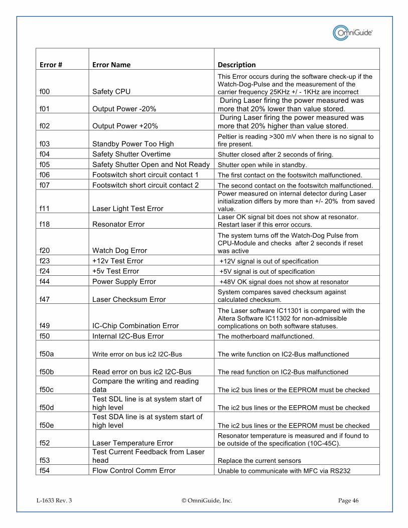
L-1633 Rev. 3 © OmniGuide, Inc. Page 46
/�����=� /�����+��� 1( ��4�����
-<<� $�-��*���#�
)����,�� �� ����� ���������� -�.���������;���-����������;� �;������� ���������������� -�������������-��=���*�>(:�?��6�;�@:�?�������� ������
-<@� ����� .���;><���������������-����������� .��������� �.���� ��������><��� .��������0������ �� 7�
-<>� ����� .����><���������������-����������� .��������� �.���� ��������><��������������0������ �� 7�
-<A� $��� +*�� .���) �������������������� ����BA<<��/�.�������������� ��������� �-�����������7�
-<'� $�-��*�$������0������� $�������� �� ��-����>���� � �� -�-�����7�-<(� $�-��*�$������������ �C ��"�� *� $������ ����.������������ +*7�-<D� ! ��.������� ����������� ������@� )���-������ ������ ������- ��.��������-���� �� 7�-<E� ! ��.������� ����������� ������>� )������ � �� ������ ������- ��.��������-���� �� 7�
-@@� ������������)����,�� ��
� .��������� � ����������� ����� �� �������������������?��� �� �--����+*�� ���������6;�><���-� ����0� �0���7�
-@F� "�� ��� ��,�� ��������:��������+��� ���� ���� .������� ��� �7�"��������������-��������� �� ����7��
-><� ������� ��,�� ��
)����*���������� --����������;� �������-� ����#;� ����� ����������-����>���� � ���-�������.�������0��
->A� �@>0�)����,�� �� ��@>/����������� �� -������-����� ��->'� �(0�)����,�� �� ��(/����������� �� -������-����� ��-''� � .���$���*�,�� �� ��'F/�:�������� ���� ���� .������� ��� ��
-'E� ��������������,�� ��$*������ ���������0� ������������������������� ��������7�
-'G� ��;������ �+����� ��,�� ��
)���������� -�.������@@A<@����� ����� �.���������������$ -�.������@@A<>�- ��� �;� �����+���� �������� ��� ��+ ���� -�.�����������7�
-(<� ����������>�;%��,�� �� )���� ����+ �� ����-���� �� 7�
-(<�� ��������� �� ��+����>��>�;%�� )���.�����-���� �� ����>;%�����-���� �� �
-(<+� "�� ���� �� ��+����>��>�;%�� )������ �-���� �� ����>;%�����-���� �� �
-(<��� ����������.��������� ���� ���� ���� )�����>�+�������� ������,,�"������+�������� �
-(< �)����$���������������*����������� -��������0��� )�����>�+�������� ������,,�"������+�������� �
-(<��)����$���������������*����������� -��������0��� )�����>�+�������� ������,,�"������+�������� �
-(>� ������)����������,�� ��"�� ��� ���������������������� ��� ��-�- � �� �+�� ��� �� -����������-����� ���@<�;'(��7�
-(A�)�����������!�� +����-� ����������� � "���������������������� ���
-('� !� .�� ��� ��� ���,�� �� #��+���� �� ���������.�����!��0���"$>A>�

L-1633 Rev. 3 © OmniGuide, Inc. Page 47
-('�� �!�����-��,�� �� �!�� --�����������������<7<@<����� ������������-((� "!���� ���,�� �� #��+���� �� ���������.����"!���0���"$>A>��<@� � ������ � �������� ��� �����<>� ������ ,���.����������� ��<A� )����������� �� .� ��+����������� �� .��<'� )����������� ������ ��+����������� �������<(� ��� ��*� ��� ��*�� �������<D� !���,�� �� !���� ������������(<� !�+����� !�+������ 0� �-� ���*�������(@� ����#� ��-� .� ���� �����-� .�� �� .���(>� ����0��-� .� ���� �����-� .�� �������(A� !�+�����������,�� �� �������� ���� ��������-�+��� ������('� !�+��������,8������ ������� !�+���������8������ �� ������((� !�+��������#�������� .� !�+����� ����0� ��*���(D� ������#� ����������� ����������-� .�� �� .�
�GUIDANCE AND MANUFACTURER’S DECLARATION ELECTROMAGNETIC EMISSION
����������������� ����������� ����� ������ ����������
)����������������� � �- ������������������ �����������0�� �����������-�� �+�� .7�)������ ���� ���������� -������������� � �������������������� �������������0�� �������������������� ���������� ����������������� ���������!�
�"�#�����"!������� ������$�"�@@�
�"#��@� )�������������"!������*� ��*�- ���������������-���� �7�)����- ��������"!������� �������0��*�� .��� �����������*�� ��������*������-��������������+*������� �����=������7�
"!������� ������$�"�@@�
���$$�%� )����������������+���- ����������������+���������� ���������� ��������� ��� ��� ������*�� ������ �� ������ .;0 ������� .�������*����. ����������������+�� ������� �- �� ���������� ���7�
���� ����������� ����,��D@<<<;A;>�
���$$�%�

L-1633 Rev. 3 © OmniGuide, Inc. Page 48
ELECTROMAGNETIC IMMUNITY - I
����������������� ����������� ����� ������ �������� $�
)����������������� � �- ������������������ �����������0�� �����������-�� �+�� .7�)������ ���� ���������� -������������� � �������������������� �������������0�� ������
���"���%������ ��&'&'(�������� ���
������������ ���
����������������� ���������!��"�#�����
,����� ������� ����������,$�����,��D@<<<;';>�
H�D��/�� ������H�F��/�����
� �������.������,��D<D<@��
!� ����� � �+��. ��� ������� ��������������7��-�-� �������� 0��� �.�����*����������������������������0����� ��*��� � �+�����������A<�7�
,����������-�������������6+�����,��D@<<<;';'�
H�>��/�- ��� .�������*�������H@��/�- ������6 ����������
� �������.������,��D<D<@�
������� .���=����*��� � �+������� -����*������� ��������� ��� ���������0�� �����7�
$�����,��D@<<<;';(�
H�>��/�� �� ��� ��H�@��/� �--���������� ��
� �������.�����,��D<D<@�
������� .���=����*��� � �+������� -����*������� ��������� ��� ���������0�� �����7�
/ ������ ������� ������������ ����� �0 ������0������ ��� ��� .�������*�������������,��D@<<<;';@@�
I�(���#)���BG(��� ������#)��- ���<�(��*�����'<���#)��D<��� ������#)��- ��(��*�����E<���#)��A<��� ������#)��- ��>(��*�����I(���#)�BG(��� ������#)��- ��(�����
� �������.�����,��D<D<@�
������� .���=����*��� � �+������� -����*������� ��������� ��� ���������0�� �����7��-��������� -�������������=������ ����� � ������ �� ������ .������������������ ������������� ���� � ����������������+��� .��� �-� ���������������+���� .�������*� ����+�����*7�
/ ������-������ ���6�-������������� ����,��D@<<<;A;A�
��$$�

L-1633 Rev. 3 © OmniGuide, Inc. Page 49
� .���-��=���*��(<6D<��?�����������-��� ���,��D@<<<;';F�
A��6�� A�6�� � .���-��=���*����������-��� ���� � �+�������0������������������� -����*������� ���� ��������*������� ��������� ��� ���������0�� �����7�
C),J�#)����������������0 ��������� ��� �������������� �� -������������0���
ELECTROMAGNETIC IMMUNITY – II
����������������� ����������� ������ ������ �������� $�
)����������������� � �- ������������������ �����������0�� �����������-�� �+�� .7�)������ ���� ���������� -������������� � �������������������� �������������0�� ���������"���%������
��&'&'(!������� ���
������������ ��� ����������������� ���������!��"�#�����
"� ���� �"!��,��D@<<<;';D�
A�/�--���F<���?�� �>(<<���?�
A�/�--���/@��� �- ����� ��,��D<D<@�
� ���+����� �� +����"!�� �������� ����=��������� � �+���� �� ��� ����� ���*������ -���������������� ������+����������������� ���� � ��������� �� ���������������� �-� �������=��� ���������+���� �����-��=���*� -����������������7����������#�#������������#�������)����K�L�A�(�J��@�M�N�����K�L�A�(�J��@�M�N���F<���?�� �F<<���?����K�L�E�J��@�M�N���F<<���?�� �>�(���?�������������������8���� ����� .���������� -��������������������.������������ � ����� ��������������������-��������� � ����������� ���� � ��������� �� ���������������������7��
!��� �����������-� ��-�8� �"!������������������ �������� �+*���������� ����������������0�*������ � �+����������������� �����������0������������-��=���*������7�+��
�����-���������*� �����������0������*�� -��=������������ �.���������- �� .�����*�+ �J���
� � ��� �"!��,��D@<<<;';A�
A/6���@(<���?�� �F<���?�
A�/6���,@��� �- ����� ��,��D<D<@�
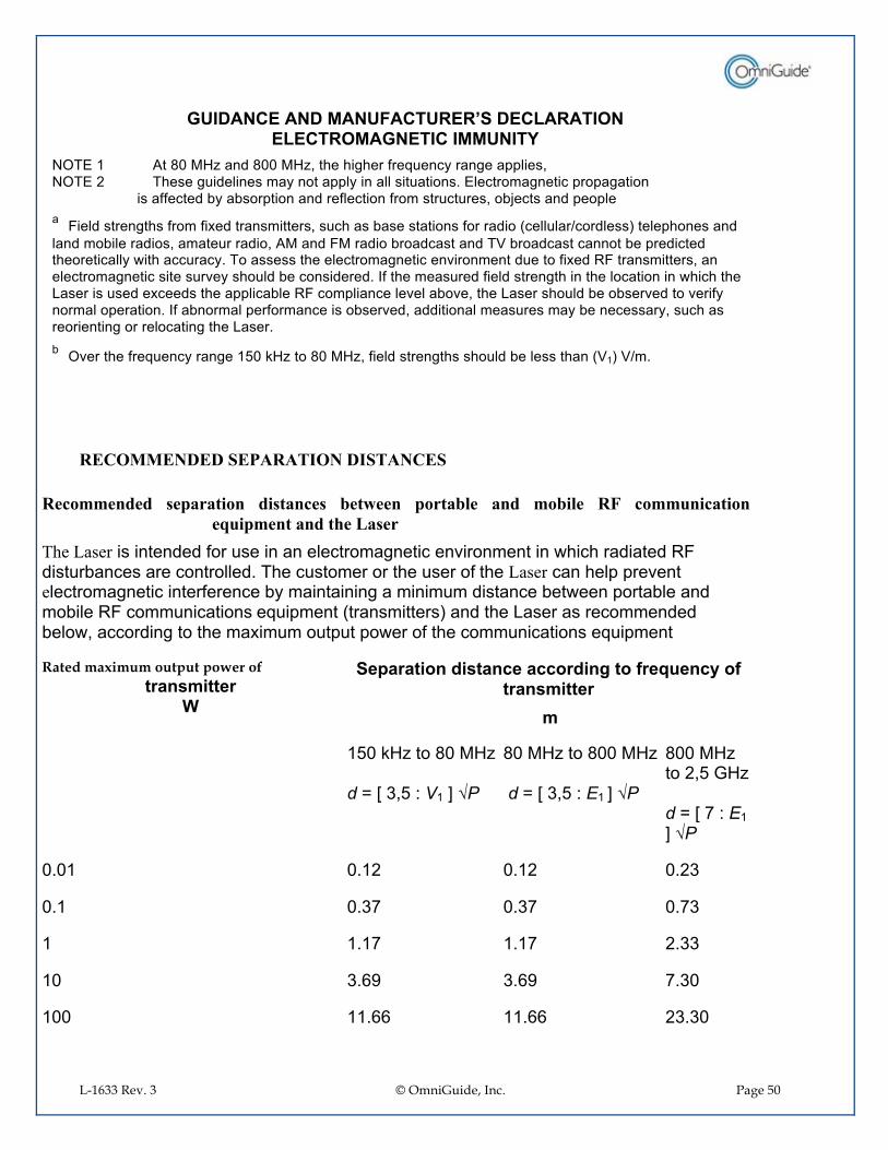
L-1633 Rev. 3 © OmniGuide, Inc. Page 50
����������������� ����������� ������ ������ �������� $�
C),�@� ���F<���?��� �F<<���?�������������-��=���*����������������C),�>� )������� ���������*�� ������*�������������� ��7�,����� ����������� ������ ���������������������������--���� �+*��+� ���� ���� ���-����� ��-� ������������ +O������� ��� �������!��� �����������-� ��-�8� ����������������������+��������� ���- ���� � ���������6� � ������������ ������ ���� �� +������ � ������������ � ������� �!���� � �+� � ������� �)/�+� � ��������� ��+����� ���� ���� ��������*�.����������*7�) ������������������ �����������0�� ������ ��� �-�8� �"!������������������������ ����������������0�*��� � �+��� ��� ��� 7��-����������� �-��� ������������������ ���� �����.�������������������� ��8��� �������������+���"!�� �����������0����+ 0��������������� � �+�� +���0� �� �0���-*�� ����� ������ �7��-��+� ��������- ���������� +���0� ��� ��� ��������������*�+����������*����������� ��������� ����� ����������������7��+��0�������-��=���*�������@(<���?�� �F<���?��-��� ������������� � �+�������������/@��/6�7��
RECOMMENDED SEPARATION DISTANCES
Recommended separation distances between portable and mobile RF communication equipment and the Laser
The Laser��������� � �- ����������������� �����������0�� ���������.������� ���� �"!� ����+����������� ��� ��� 7�)������ ���� ���������� - ����Laser�������������0����e����� ��������������-�������+*���������������������� ��������+��.����� ���+����� �� +����"!�� �������� �� �=������������������������ ����������������� ���� � �+�� .����� � ����� �������8���� ����� .��� -������ �������� ����=�������
Rated maximum output power of ������������
*�
�����������#�������������#�������+��,"���%��+�������������
��
@(<���?�� �F<���?����K�L�A�(�J��@�M�N���
F<���?�� �F<<���?�����K�L�A�(�J��@�M�N��
F<<���?�� �>�(���?����K�L�E�J��@�M�N���
<7<@� <7@>� <7@>� <7>A�
<7@� <7AE� <7AE� <7EA�
@� @7@E� @7@E� >7AA�
@<� A7DG� A7DG� E7A<�
@<<� @@7DD� @@7DD� >A7A<�

L-1633 Rev. 3 © OmniGuide, Inc. Page 51
Recommended separation distances between portable and mobile RF communication equipment and the Laser
For transmitters rated at a maximum output power not listed above, the recommended separation distance d in meters (m) can be estimated using the equation applicable to the frequency of the transmitter, where P is the maximum output power rating of the transmitter in watts (W) according to the transmitter manufacturer. NOTE 1 At 80 MHz and 800 MHz, the separation distance for the higher frequency range applies. NOTE 2 These guidelines may not apply in all situations. Electromagnetic propagation is affected by absorption and reflection from structures, objects and people.�
�REFERENCES • Lasers: The Perioperative Challenge, Kay A. Ball, Mosby Publishing, ISBN 081510524X • Lasers and Optical Fibers in Medicine, Abraham Kazir, Academic Press, ISBN 0124019404 • Laser Surgery and Medicine, Principles and Practice, Carmen A. Puliafito, John Wiley & Sons, ISBN
0471120707 • Medical Laser Endoscopy, Dennis M. Jensen, Kluwer Academic Publisher, ISBN 07920305795 • Medical Lasers and Their Safe Use, D.H. Sliney & S.L. Trokel, Springer-Verlag, ISBN 3540978569
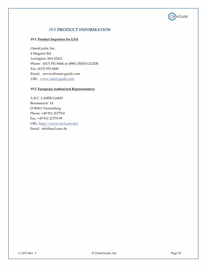
L-1633 Rev. 3 © OmniGuide, Inc. Page 52
�PRODUCT INFORMATION
19.1.�Product Inquiries for USA OmniGuide, Inc. 4 Maguire Rd. Lexington, MA 02421 Phone: (617) 551-8444 or (888) OMNI-GUIDE Fax: (617) 551-8445 Email: [email protected] URL: www.omni-guide.com
19.2.�European Authorized Representative
A.R.C. LASER GmbH Bessemerstr. 14 D-90411 Nuremberg Phone: +49 911 21779-0 Fax: +49 911 21779-99 URL: http://www.arcLaser.de/ Email: [email protected]
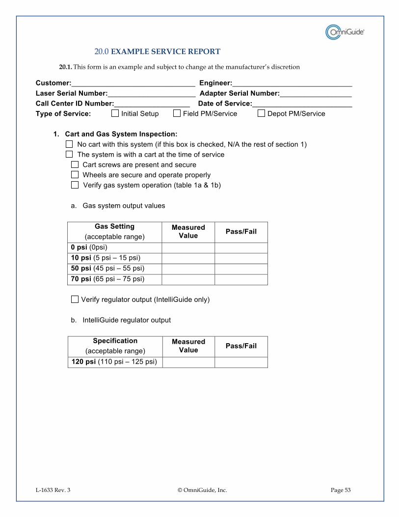
L-1633 Rev. 3 © OmniGuide, Inc. Page 53
�EXAMPLE SERVICE REPORT
20.1.�This form is an example and subject to change at the manufacturer’s discretion "������)PPPPPPPPPPPPPPPPPPPPPPPPPPPPPPP���������)PPPPPPPPPPPPPPPPPPPPPPPPPPPPPP���������������"�-��)PPPPPPPPPPPPPPPPPPPPPP���#��������������"�-��)PPPPPPPPPPPPPPPPPP���������������"�-��)PPPPPPPPPPPPPPPPPPP����������+���� ���)PPPPPPPPPPPPPPPPPPPPPPPPP� %����+���� ���)���������� ���������$���������� �!��� ���6$��0������������� ���� ����6$��0�����
(.� ������#������%���������������)���C ������.����������*�������-������+ 8���������� ��C6����������� -������ ��@����)����*��������.����������������������� -����0����� ���������.���������������� �������� ������������������� � ��������� ����*���/���-*������*����� ������ �����+���@����@+��
��7� �����*����� ����0������
��������������
��������+��������������"��#�/��"�� 0���1�����
'������<����� � �('������(�����Q�@(������ � �2'������'(�����Q�((������ � �3'������D(�����Q�E(������ � ��
�/���-*������� �� �������������� �� ��*���+7� ��������� �������� �� ����
������+��������
��������+��������������"��#�/��"�� 0���1�����
(4'������@@<�����Q�@>(������ � ����
�������
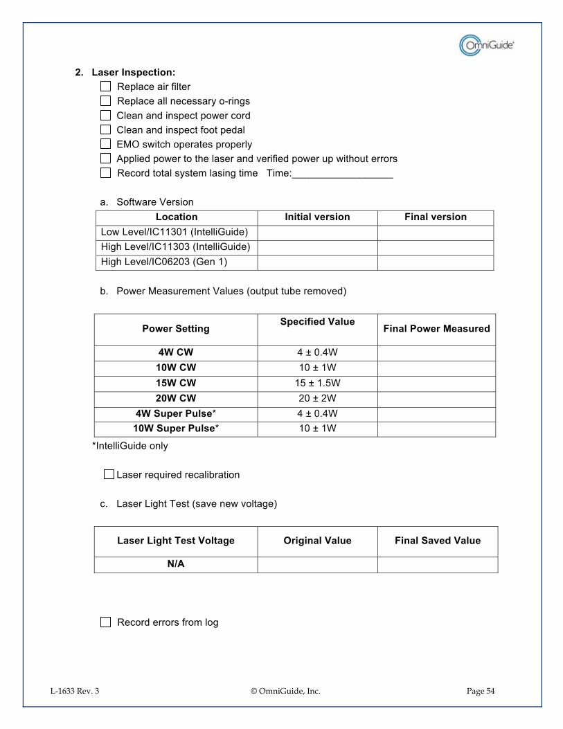
L-1633 Rev. 3 © OmniGuide, Inc. Page 54
4.� ����������������)���"�����������-��������"�������������������*� ;������� �������� ���������� .���� � �� �������� ���������- ���� ���� ,���.����� ���������� ����*�� ������ �� .���� ������������� �0���-�� �� .�����.��� ����� �����"�� � �� �����*�������������������)���JPPPPPPPPPPPPPPPPPP�
��7� $ -�.����/���� ��
��������� �������� ������� ������ �������� .���0��6��@@A<@����������� ��� � ��������0��6��@@A<A����������� ��� � ��������0��6��<D><A������@�� � �
�+7� � .��������������/������ �����+����� 0� ��
�
0�5����������� �����+��#�/��"���
������0�5�������"��#�
6*�*�� '�H�<7'�� �('*�*�� @<�H�@�� �(2*�*�� @(�H�@7(�� �4'*�*�� ><�H�>�� �
6*��"����0"����� '�H�<7'�� �('*��"����0"����� @<�H�@�� �
���������� �� ��*��� ���������=��� �������+���� ���
��7� ������������)�������0����.�0 �������
�
���������7�� ����/������� ���������/��"�� �������� �#�/��"��
�1�� � ���
���"�� � ���� ���-� ��� ��
��
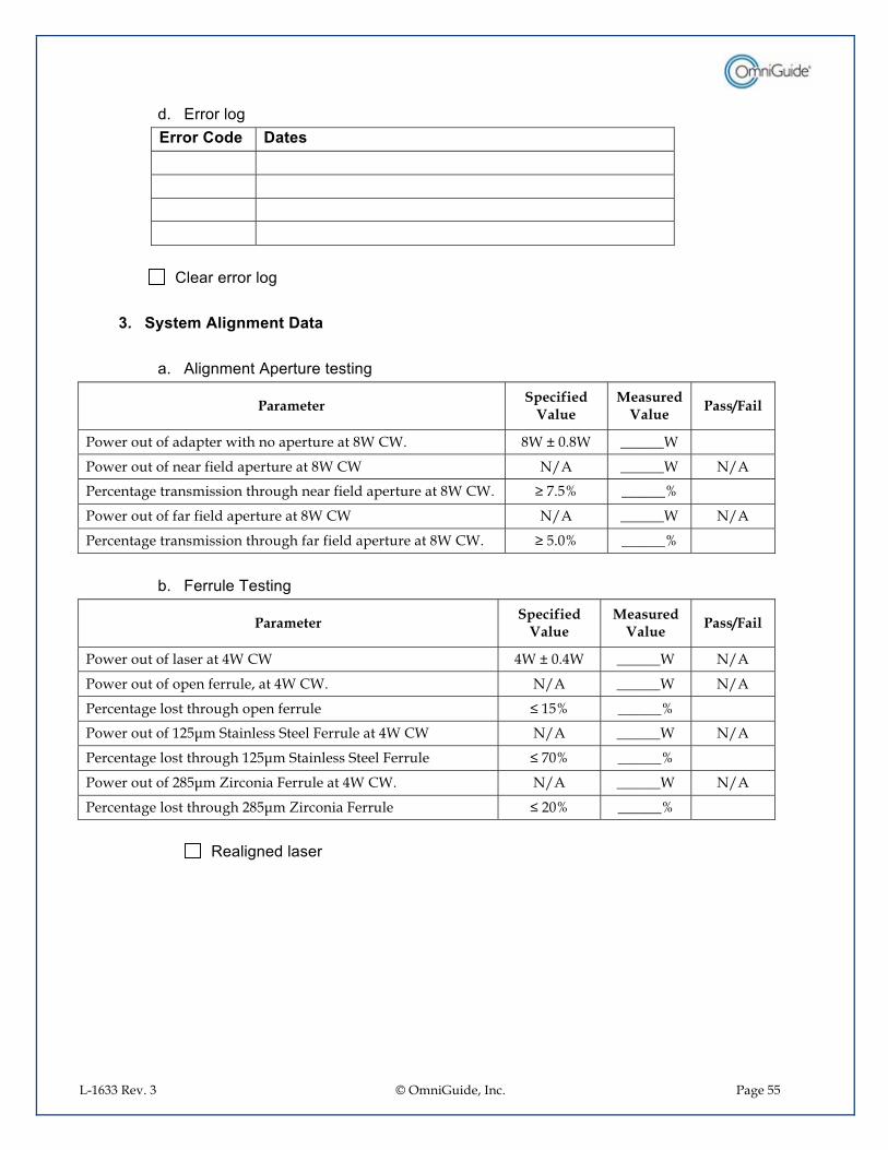
L-1633 Rev. 3 © OmniGuide, Inc. Page 55
7� ,�� ��� ��������#�� ������� �� �� �� �
�������� ����������� ��� ���8.� �%��������������������
��7� ��������������������������
Parameter Specified Value
Measured Value Pass/Fail
Power out of adapter with no aperture at 8W CW. 8W ± 0.8W ______W
Power out of near field aperture at 8W CW N/A ______W N/A
Percentage transmission through near field aperture at 8W CW. ≥ 7.5% ______%
Power out of far field aperture at 8W CW N/A ______W N/A
Percentage transmission through far field aperture at 8W CW. ≥ 5.0% ______% �
+7� !������)�������
Parameter Specified Value
Measured Value Pass/Fail
Power out of laser at 4W CW 4W ± 0.4W ______W N/A
Power out of open ferrule, at 4W CW. N/A ______W N/A
Percentage lost through open ferrule ≤ 15% ______%
Power out of 125μm Stainless Steel Ferrule at 4W CW N/A ______W N/A
Percentage lost through 125μm Stainless Steel Ferrule ≤ 70% ______%
Power out of 285μm Zirconia Ferrule at 4W CW. N/A ______W N/A
Percentage lost through 285μm Zirconia Ferrule ≤ 20% ______% �
��"������� ���������������

L-1633 Rev. 3 © OmniGuide, Inc. Page 56
�7� !�+���)�������
Parameter Specified Value
Measured Value Pass/Fail
Power out of open Ferrule at 15W CW (4W CW without gas) N/A ______W N/A Fiber ID N/A N/A Power out of Fiber N/A ______W N/A Percentage Lost through Fiber <60% ______%
���"!�����������-���� ������� ����*
�'7� 0�����,"���������#��"��7�����������0�����"�-��� 0��������� �����"�-��� 9�%�
� � � �� � � �� � � �� � � �
�� "������������������ � ������C�8����� �JPPPPPPPPPPPPPPPP�
�!���������� ����=��� JPPPPPPPPPPPPPPPPPPPPPPPPPPPPPPPPPPPPPPPPPPPPPPPPPPPPPPPPPPPPP�PPPPPPPPPPPPPPPPPPPPPPPPPPPPPPPPPPPPPPPPPPPPPPPPPPPPPPPPPPPPPPPPPPPPPPPPPPPPPPPPPPPPPPPPPPPPPPPPPPPPPPPPPPPPPPPPPPPPPPPPPPPPPPPPPPPPPPPPPPPPPPPPPPPPPPPPPPPPPPPPPPPPPPPPPPPPPPPPPPPPPPPPPPPPPPPPPPPPPPPPPPPPPPPPPPPPPPPPPPPPPPPPPPPPPPPPPPPPPPPPPPPPPPPPPPPPPPPPPPPPPPPPPPPPPPPPPPPPPPPPPPPPPPPPPPPPPPPPPPPPPPPPPPPPPPPPPPPPPPPP��C ���PPPPPPPPPPPPPPPPPPPPPPPPPPPPPPPPPPPPPPPPPPPPPPPPPPPPPPPPPPPPPPPPPPPPPPPPPPPPPPPPPPPPPPPPPPPPPPPPPPPPPPPPPPPPPPPPPPPPPPPPPPPPPPPPPPPPPPPPPPPPPPPPPPPPPPPPPPPPPPPPPPPPPPPPPPPPPPPPPPPPPPPPPPPPPPPPPPPPPPPPPPPPPPPPPPPPPPPPPPPPPPPPPPPPPPPPPPPPPPPPPPPPPPPPPPPPPPPPPPPPPPPPPPPPPPPPPPPPPPPPPPPPPPPPPPPPPPPPPPPPPPPPPPPPPPPPPPPPPPPPPPPPPPPPPPPPPPPPPPPPPPPPPPPPPPPPPPPPPPPPPPPPPPPPPPPPPPPPPPPPPPPPPPPPPPPPPPPPPPPPPPPPPPPPPPPPPPPPPPPPPPPPPPPPPPPPPPPPPPPPPPPPPPPPPPPPPPPPPPPPPPPPPPPPPPPPPPP��� .�����������JPPPPPPPPPPPPPPPPPPPPPPPPPPPPPPP���������+���� �� �JPPPPPPPPPPPPPPPPPPPP�� .��� ����� ����JPPPPPPPPPPPPPPPPPPPPPPPPPPPPP���������+���� �� �JPPPPPPPPPPPPPPPPPPPP����������������JPPPPPPPPPPPPPPPPPPPPPPPPPPPP����������+���� �� �JPPPPPPPPPPPPPPPPPPPP�


![Mastering Pool [G. Fels]](https://img.pdfslide.us/doc/110x75/5695d24c1a28ab9b0299df2f/mastering-pool-g-fels.jpg)