Embed Size (px)
Citation preview
© 2012 Westinghouse Electric Company LLC. All Rights Reserved.Westinghouse Non-Proprietary Class 3
Feedwater Control Digital UpgradesFeedwater Control Digital Upgrades Project Approach & Experience
FSRUG Conference/WorkshopJanuary 23-26, 2012
Embassy Suites San Antonio TX
V h Th
Embassy Suites, San Antonio, TX
Vaughn ThomasPrincipal EngineerWestinghouse Nuclear AutomationOperating Plant Support Upgrades
1
Operating Plant Support Upgrades

© 2012 Westinghouse Electric Company LLC. All Rights Reserved.Westinghouse Non-Proprietary Class 3
Characteristic Goals of FW Control Upgradespg
• Address I&C platform challenges:E i t b l– Equipment obsolescence
– Single point vulnerabilities (SPV’s)– Limitations of analog technology– Unreliable measurements
• Address I&C operational challengesU l d t / t il t– Unplanned outages/curtailments
– Operator demands– Stability, performancey
2
© 2012 Westinghouse Electric Company LLC. All Rights Reserved.Westinghouse Non-Proprietary Class 3
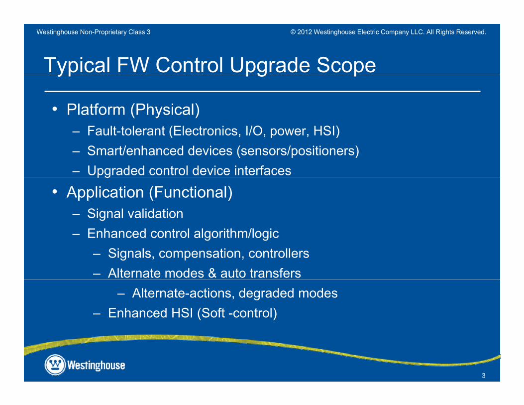
Typical FW Control Upgrade Scopeyp pg p
• Platform (Physical)F l l (El i I/O HSI)– Fault-tolerant (Electronics, I/O, power, HSI)
– Smart/enhanced devices (sensors/positioners)– Upgraded control device interfacespg
• Application (Functional)– Signal validation– Enhanced control algorithm/logic
– Signals, compensation, controllers– Alternate modes & auto transfers
– Alternate-actions, degraded modes– Enhanced HSI (Soft -control)
3
© 2012 Westinghouse Electric Company LLC. All Rights Reserved.Westinghouse Non-Proprietary Class 3
WEC FW Upgrades Timelinepg
• Generation I : Initial installed system– Analog (Foxboro H-line, 7100, 7300 Platform)– 3-Element / Independent High & Low Power (HP & LP) modes
• Generation II: Late ’80sGeneration II: Late 80s– Digital (WDPF Platform)– Enhanced 3-Element / Integrated HP & LP modes
• Generation III: Late ‘90’s– Gen II + Enhanced Features + New Platform (Ovation)
• Generation III B: > 2009• Generation III-B: > 2009– Common core design applied for BWRs
4
© 2012 Westinghouse Electric Company LLC. All Rights Reserved.Westinghouse Non-Proprietary Class 3
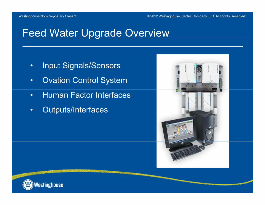
Feed Water Upgrade Overview
I t Si l /S
pg
• Input Signals/Sensors
• Ovation Control System
• Human Factor Interfaces
• Outputs/Interfaces
5
© 2012 Westinghouse Electric Company LLC. All Rights Reserved.Westinghouse Non-Proprietary Class 3
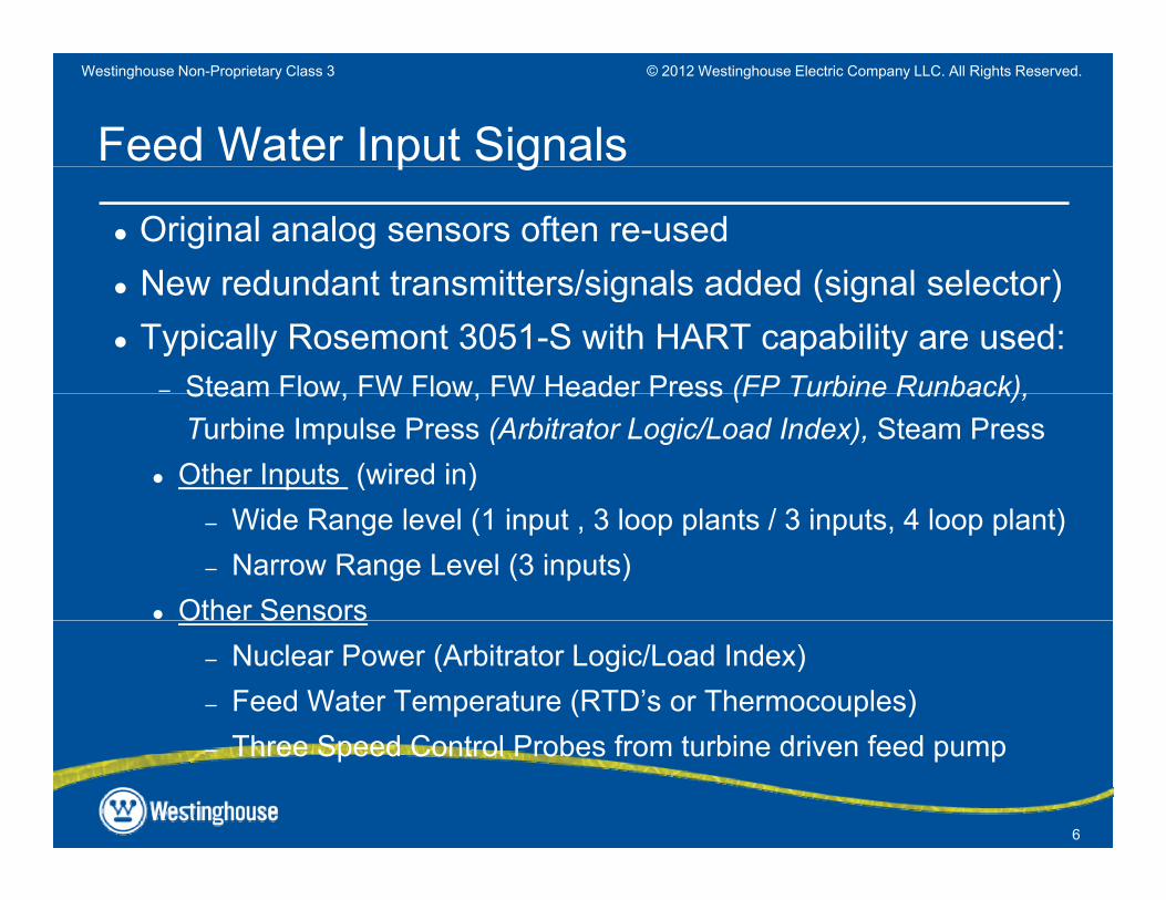
Feed Water Input Signals
● Original analog sensors often re-usedNew redundant transmitters/signals added (signal selector)
p g
● New redundant transmitters/signals added (signal selector)● Typically Rosemont 3051-S with HART capability are used:
– Steam Flow, FW Flow, FW Header Press (FP Turbine Runback),Steam Flow, FW Flow, FW Header Press (FP Turbine Runback), Turbine Impulse Press (Arbitrator Logic/Load Index), Steam Press
● Other Inputs (wired in)– Wide Range level (1 input , 3 loop plants / 3 inputs, 4 loop plant)– Narrow Range Level (3 inputs)
● Other SensorsO e Se so s– Nuclear Power (Arbitrator Logic/Load Index)– Feed Water Temperature (RTD’s or Thermocouples)
6
– Three Speed Control Probes from turbine driven feed pump
© 2012 Westinghouse Electric Company LLC. All Rights Reserved.Westinghouse Non-Proprietary Class 3
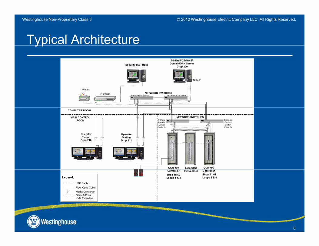
Digital FW System Typical Configuration
• 1,2, 3 or 4 Redundant Controllers:– Dependent on design basis
• HMI > 2 Operator Workstations with soft controlsSLIM M/A St ti f l t d t l– SLIM M/A Stations for selected controls
• 1 Engineer’s/Data Base Server Workstation– Anti-virus stationAnti virus station
• Network Equipment• New Cabinets (or retrofit existing)( g)
7
© 2012 Westinghouse Electric Company LLC. All Rights Reserved.Westinghouse Non-Proprietary Class 3
Typical ArchitectureypSS/EWS/DB/OWS/
Domain/OPH Server Drop 200
Security (AV) Host
IP Switch
Printer
Note 2
CISCO SY STEMS CISC OSYSTEM S
NETWORK SWITCHESPrimary Root Switch Back-up Root Switch
MAIN CONTROLROOM
COMPUTER ROOM
OperatorStation
OperatorStation
CISCOSY STEM S
PrimaryFan-outSwitch
(Note 1)
CISCOSYSTEM S
Back-upFan-outSwitch
(Note 1)
NETWORK SWITCHES
Drop 210
OCR 400 OCR 400Extended
Drop 211
Drop 10/62Loops 1 & 2
Controller ControllerDrop 11/61Loops 3 & 4
I/O Cabinet
Legend:
UTP Cable
Fiber Optic CableMedia ConverterOther T/P viaKVM Extenders
59.0 PCT
100
80
20
40
60
0
A
SP PV OUT
0
20
40
60
80
100
M L
Re jectto Lo cal
59.0 PCT
1 00
80
20
40
60
0
A
SP PV OUT
0
20
40
60
80
100
M L
Rejectto Loc al
8
© 2012 Westinghouse Electric Company LLC. All Rights Reserved.Westinghouse Non-Proprietary Class 3
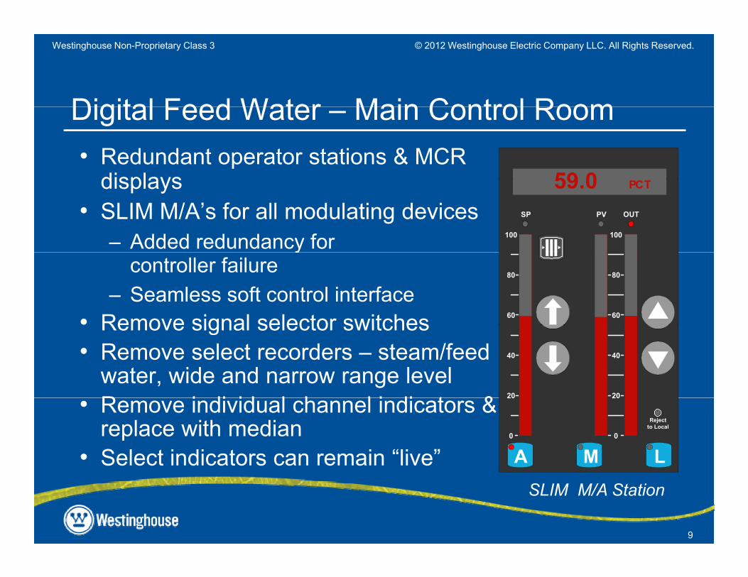
Digital Feed Water Main Control Room• Redundant operator stations & MCR
displays
Digital Feed Water – Main Control Room
59 0displays• SLIM M/A’s for all modulating devices
– Added redundancy for
59.0 PCT
100
SP PV OUT
100ycontroller failure
– Seamless soft control interface• Remove signal selector switches
80
6060
80
Remove signal selector switches• Remove select recorders – steam/feed
water, wide and narrow range levelR i di id l h l i di t & 20
40
20
40
• Remove individual channel indicators & replace with median
• Select indicators can remain “live”
20
0
A0
20
M L
Rejectto Local
9
SLIM M/A Station
© 2012 Westinghouse Electric Company LLC. All Rights Reserved.Westinghouse Non-Proprietary Class 3
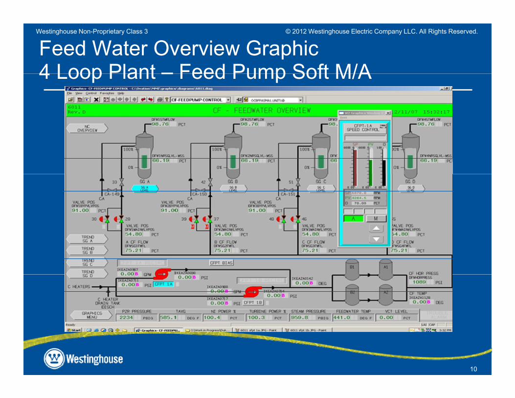
Feed Water Overview Graphic4 Loop Plant – Feed Pump Soft M/A4 Loop Plant – Feed Pump Soft M/A
10
© 2012 Westinghouse Electric Company LLC. All Rights Reserved.Westinghouse Non-Proprietary Class 3
Feed Water Output Signalsp g
● Modulating Outputs to Main FW Reg ValveTypical: redundant RLI’s w/SLIM– Typical: redundant RLI s w/SLIM
– Some: redundant smart positioners (redundancy at valves)
● Modulating Outputs to Bypass FW Reg Valve– Typical: non-redundant RLI w/SLIM M/A interface– Some: redundant RLI’s w/SLIM
● Feed Pump control● Feed Pump control● Non-Integrated > Typical: non-redundant RLI w/SLIM, Some: redundant
● Integrated– Typical: non-redundant Stm Vlv Positioner Output (w/single LVDT)– Some: redundant Stm Vlv Positioner Output (w/dual LVDT, servo coil)
redundant Loop interface Output w/SLIM (to electric actuator)
11
© 2012 Westinghouse Electric Company LLC. All Rights Reserved.Westinghouse Non-Proprietary Class 3
WEC Design Process for Upgradesg pg
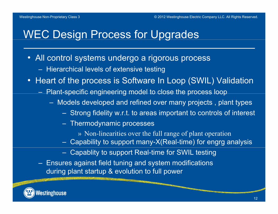
• All control systems undergo a rigorous processHi hi l l l f i i– Hierarchical levels of extensive testing
• Heart of the process is Software In Loop (SWIL) Validation– Plant-specific engineering model to close the process loopPlant specific engineering model to close the process loop
– Models developed and refined over many projects , plant types– Strong fidelity w.r.t. to areas important to controls of interest– Thermodynamic processes
» Non-linearities over the full range of plant operation– Capability to support many-X(Real-time) for engrg analysis– Capablity to support Real-time for SWIL testing
– Ensures against field tuning and system modifications during plant startup & evolution to full power
12
g p p p
© 2012 Westinghouse Electric Company LLC. All Rights Reserved.Westinghouse Non-Proprietary Class 3
WEC Design Process for Upgrades (cont’d)g pg ( )
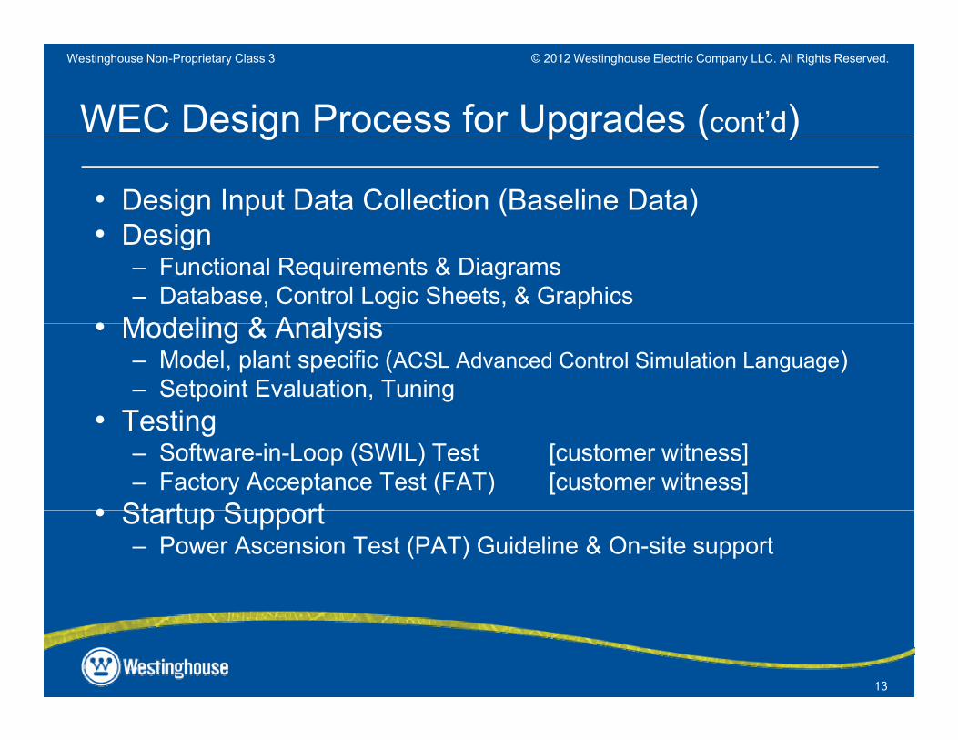
• Design Input Data Collection (Baseline Data)• Design• Design
– Functional Requirements & Diagrams– Database, Control Logic Sheets, & Graphics
• Modeling & Analysis• Modeling & Analysis– Model, plant specific (ACSL Advanced Control Simulation Language)– Setpoint Evaluation, Tuning
• Testing• Testing– Software-in-Loop (SWIL) Test [customer witness]– Factory Acceptance Test (FAT) [customer witness]
• Startup Support• Startup Support– Power Ascension Test (PAT) Guideline & On-site support
13
© 2012 Westinghouse Electric Company LLC. All Rights Reserved.Westinghouse Non-Proprietary Class 3
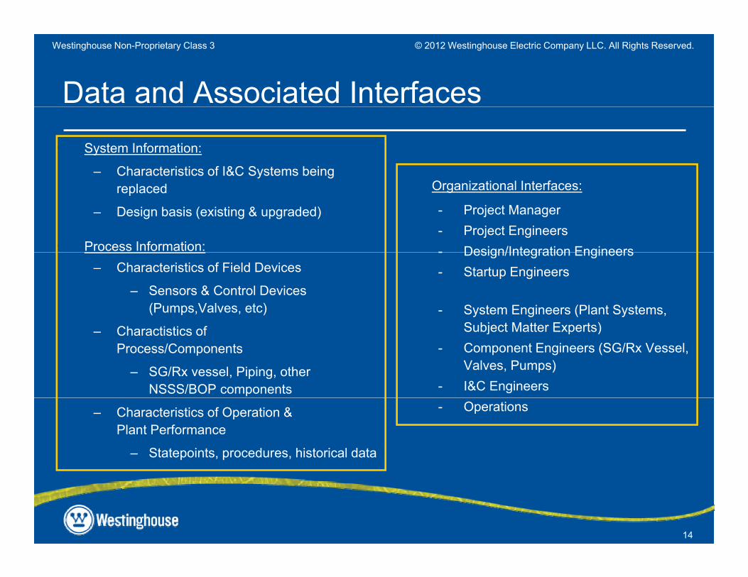
Data and Associated Interfaces• System Information:
– Characteristics of I&C Systems being replaced
– Design basis (existing & upgraded)
• Process Information:
Organizational Interfaces:
- Project Manager- Project Engineers- Design/Integration Engineers
– Characteristics of Field Devices
– Sensors & Control Devices (Pumps,Valves, etc)
- Design/Integration Engineers- Startup Engineers
- System Engineers (Plant Systems, Subject Matter Experts)– Charactistics of
Process/Components
– SG/Rx vessel, Piping, other NSSS/BOP components
Subject Matter Experts)- Component Engineers (SG/Rx Vessel,
Valves, Pumps)- I&C Engineers
– Characteristics of Operation & Plant Performance
– Statepoints, procedures, historical data
- Operations
14
© 2012 Westinghouse Electric Company LLC. All Rights Reserved.Westinghouse Non-Proprietary Class 3
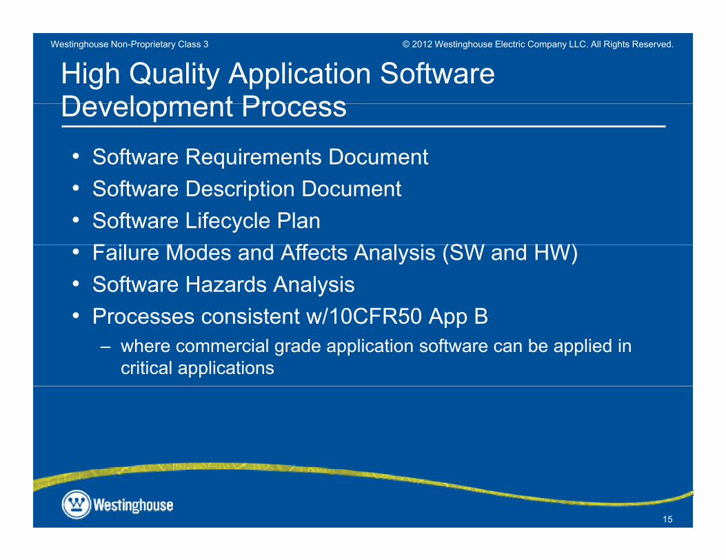
High Quality Application Software Development ProcessDevelopment Process• Software Requirements Document• Software Description Document• Software Lifecycle Plan
F il M d d Aff t A l i (SW d HW)• Failure Modes and Affects Analysis (SW and HW)• Software Hazards Analysis• Processes consistent w/10CFR50 App B• Processes consistent w/10CFR50 App B
– where commercial grade application software can be applied in critical applications
15
© 2012 Westinghouse Electric Company LLC. All Rights Reserved.Westinghouse Non-Proprietary Class 3
High Quality thru “Defense in Design”g y g
• Plant specific models, analysis, & testing w/application (SWIL)(SWIL)
• Application partitioning• Limited reliance on the control network• I/O default failure states• Hard control stations for critical components• Redundancy at all levels
16
© 2012 Westinghouse Electric Company LLC. All Rights Reserved.Westinghouse Non-Proprietary Class 3
Lessons Learned from Project Experiencesj p
• Clear project definition Address constraints (Org/Op)– Address constraints (Org/Op)
• Project Cost/Risk Drivers– Identify & manage “First-Time” elements
• Stakeholder involvement throughout• Application of the “right”, proven technology• Disciplined design process• Thorough system testing and validation
P j t t d t l• Project management and control– Effective risk management– Focused teams, strong relationships
17
, g p
© 2012 Westinghouse Electric Company LLC. All Rights Reserved.Westinghouse Non-Proprietary Class 3
Practical Implicationsp
• Early engagement of Ops– Operational needs & expectations (buy-in on features, functionality)– Training constraints
• Early recognition of schedule demands implicationsEarly recognition of schedule demands, implications• Understanding of plant/operations vs “build to spec”• Appropriate use of toolspp p
– Engineering model for dynamic testing, verification– Simulator for operator training
18
© 2012 Westinghouse Electric Company LLC. All Rights Reserved.Westinghouse Non-Proprietary Class 3
• Questions?
19