Embed Size (px)
Citation preview

10 YearWARRANTY
www.erlphase.com
Feeder Protection Relay F-PRO 4000
• Easy to use, intuitive setting and analysis software• Three-pole reclosing, with four separately-set open time
intervals.• Comprehensive and fl exible breaker monitoring using
breaker logic and I*I*t functions• Demand, Peak Demand and Energy metering features
with complete SCADA metering (DNP or Modbus)
• IEC 61850 communication via optical ports• Ethernet ports with 2 unique MAC addresses
accommodate network access security needs • IRIG-B time stamping and sample synchronization• High quality fault recording and event log• 8 setting groups for many operating conditions
Product OverviewThe F-PRO 4000 provides easy-to-use, state-of-the-art comprehensive feeder management protection for medium to high-voltage distribution lines, with ring bus and breaker-and-a-half capability, in a fully integrated protective relay solution. It provides control, automation, metering, monitoring, DFR-quality fault oscillography, fault logging and event logging, with advanced communications in a fl exible cost effective package.
• Primary and backup protection on medium and low voltage lines
• Backup protection for transmission and sub transmission lines and power transformers
• Comprehensive and inter-tie protection available
• Ring bus capability to protect and monitor lines connected to ring bus and breaker-and-a-half schemes
• Replace older electromechanical relay schemes, and metering devices in outdoor breaker control enclosures
Application

www.erlphase.com
• Voltage Transformer Supervision (60VTS)• Displays Distance to Fault value (21FL)• CB Monitoring (I² t) – accumulated and for last
operation• Total Harmonic Distortion current detection Alarm
(THD)• Voltage, Current magnitude and phase angle
• Real and Reactive Power (P & Q)• Frequency• 3Ph Real and Reactive Energy In / Out (MWh / MVARh)• THD Current value• Demand value of Phase Voltage, Current, Real /
Reactive Power, Frequency and THD.• All the protection, monitoring function, binary input
and output status
Ease of Use
• Easy-to-use, install, and maintain• Easy to order – no complex product codes• User-friendly, Windows®-based relay setting and record
analysis software• Setting software tool – relay specifi c application• On-Line setting tool
• Instantaneous operating speed - 1.0-1.3 cycle • Low Set Overcurrent (50LS)• Dir/Non-Dir Over current Protection (67/51/50)• Dir/Non-Dir Measured ground fault Protection
(67G/51G/50G) with Restricted Earth Fault (64REF) protection option
• Dir/Non-Dir Derived neutral fault Protection (67N/51N/50N)
• Over/Under Voltage Protection (59/27)• Negative Sequence Over Current Protection (46)• Directional Real/Reactive Power Protection (32P/32Q)• Over/Under Frequency Protection (81O/81U)• Rate Of Change of Frequency Protection (81R) • Phase Distance (21P)• Circuit Breaker Failure Protection (50BF)
• Four-shot Auto-Reclose function (79) with dead line/dead bus control and sync check
• Synchrocheck (25)• Unique Breaker LogicTM functions for breaker failure
detection and monitoring• Watt, VAR directional fl ow detectors as well as
undervoltage, overvoltage and over/under frequency functions (Freq ROC) to provide protection for issues such as inter-tie protection needs
• Three-pole reclosing, with four separately-set open time intervals.
• Flexible programmable logic for building customized schemes with ProLogicTM – 10 control logic statements (total of 80 statements)
• 8 setting groups with unique Group Logic Control Statements with full Boolean graphics
Metering and Monitoring
• Substation automation cost – includes IEC 61850 protocol to display and transfer operational data via local-area network (LAN) for local HMI and wide-area network (WAN) for remote monitoring SCADA
• Engineering, installation and commissioning cost – IEC 61850 GOOSE messages communicate high-speed information between IEDs on the substation LAN such as transfer trips, interlocking, load-shedding and commands
• Product setting time – 240 x 128 LCD graphical user interface provides convenient means to check/change specifi c settings and parameters
• Front panel indicators – 11 user-confi gurable LEDs, Relay Functional, IRIG-B Functional, Service Required, Test Mode, Alarm
Protection & Control
Features & Benefi ts
Reduce Installation and Operation Cost

www.erlphase.com
Flexible Communications
• 2 rear ports, 100BASE-TX RJ-45 or 100BASE-FX 1300 nm multimode optical with ST style connector
• Ethernet ports with 2 unique MAC addresses that easily accommodate network access security needs
• Front panel USB and 100BASE-TX RJ-45 Ethernet port interfaces
• IEC 61850 Station Bus on a dedicated optical/copper Ethernet Port
• Enhanced DNP3 SCADA communication protocol including user-selectable point lists, class support and multiple master station support
• Modbus SCADA communication protocol
• IRIG-B port (through BNC connector) for precise time stamping and sample synchronization
• Serial communication port• 30 virtual inputs for local and remote control• Optional internal modem
• Exceptional fault recording capabilities (with 96 samples/cycle or 5760Hz)
• Up to 75 x 2 second transient records and optionally event records
• Demand, Peak Demand and Energy metering features with 30 to 360 day load trending (integrating, rolling or thermal modes)
• Sequence of Event Recorder – 250 Events with 1 ms resolution
• Compressed event record capabilities - a compressed sequence of event fi le is created approximately every 250 events
Substation Automation – Ethernet Ready
Multi-Functional Recording and Event Logging
• Display multiple channels simultaneously and combine records
• Display multiple component voltage, current or summed channels
• Display THD, harmonic magnitude• Zoom, alignment, scaling, unit functions• Record summaries including event lists• COMTRADE, PTI and MS Excel export
RecordGraphTM and RecordBase ViewTM
www.erlphase.com
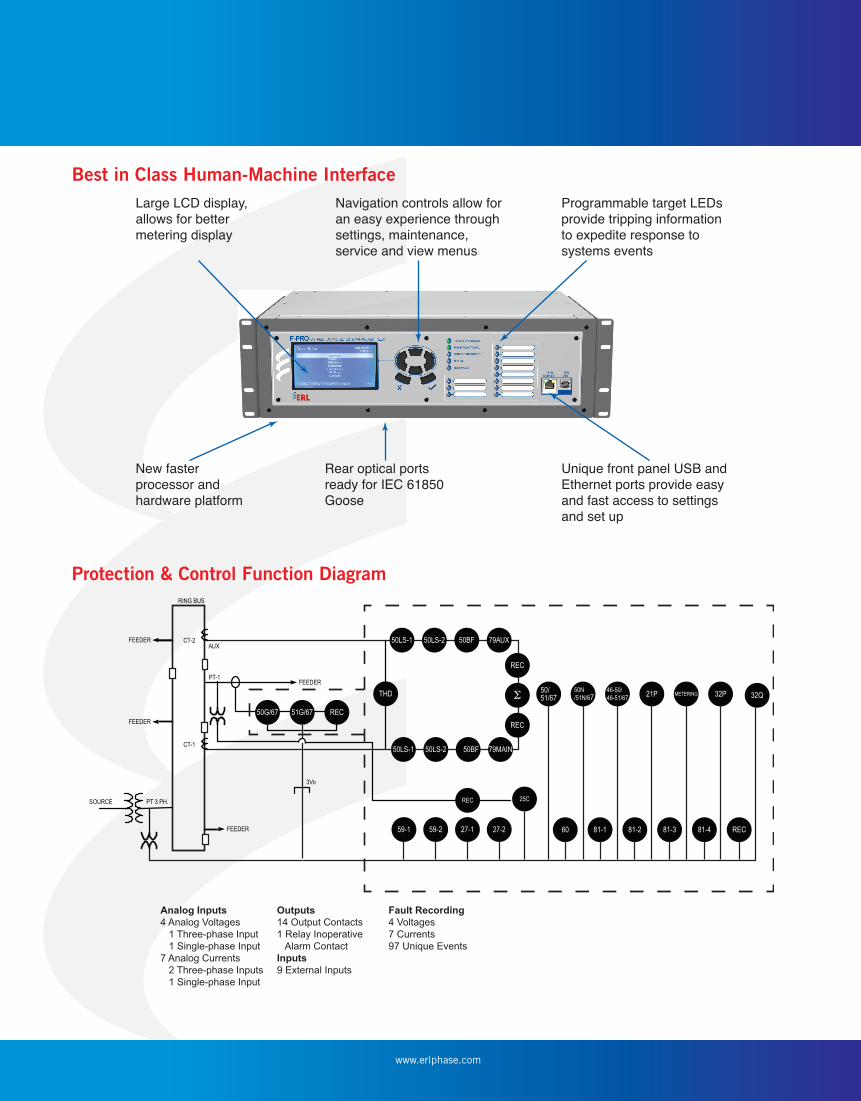
Protection & Control Function Diagram
Best in Class Human-Machine InterfaceNavigation controls allow foran easy experience throughsettings, maintenance,service and view menus
Rear optical portsready for IEC 61850Goose
Programmable target LEDsprovide tripping informationto expedite response to systems events
Unique front panel USB andEthernet ports provide easyand fast access to settingsand set up
Large LCD display,allows for bettermetering display
New fasterprocessor andhardware platform
50LS-1 50LS-2FEEDER
RING BUS
SOURCE
AUX
CT-1
CT-2
PT-1
50BF 79AUX
50LS-1 50LS-2 79MAIN
32QTHD
50BF
REC51G/6750G/67FEEDER
FEEDER
FEEDER
3Vo
PT 3 PH.
REC
REC
REC
59-1 59-2 27-1 27-2 81-2 81-3 81-4 REC60 81-1
25C
32P50/51/67
50N/51N/67
46-50/46-51/67 21P METERING
Analog Inputs
4 Analog Voltages
1 Three-phase Input
1 Single-phase Input
7 Analog Currents
2 Three-phase Inputs
1 Single-phase Input
Outputs
14 Output Contacts
1 Relay Inoperative
Alarm Contact
Inputs
9 External Inputs
Fault Recording
4 Voltages
7 Currents
97 Unique Events

www.erlphase.com
Detailed Specifi cations F-PRO 4000 Feeder Protection Relay Item Quantity/Specs Notes
General Nominal Frequency 50 or 60 Hz
Power Supply 43 – 275 Vdc, 90 – 265 Vac, 50/60 Hz Power Consumption: 25 – 30 VA (ac) 25 – 30 W (dc)
Memory Settings and records are stored in non-volatilememory
Records are stored in a circular buffer
Protection Functions IEEE Device 50LS, 50BF, 50/51/67, 50N/51N/67, 46-50/46-51/67, 50G/51G/67, 25/27/59 (25C), 21P, 59, 27, 32(P&Q), 60, 79, 81 and THD
2 x 3-phase current inputs (6 current channels)1 x 3-phase voltage inputs (3 voltage channels)1 x 1-phase voltage input for sync check1 x 1-phase current input for Measured Earth fault
Ring bus confi guration and integrated HVbreaker auto-recloser
ProLogicTM 10 statements per setting group, breaker logic 5 inputs/statement, 4 timers/statement
Setting Groups 8 (16 group logic statements per setting group) Total: 128 group logic statements
Recording Transient (Fault) 96 s/c oscillography of all analog and external input
digital channels User-confi gurable 0.2 to 2.0 secondsRecord length and 10cycles pre-fault length
Trend Demand metering: trending, integrating, rolling, thermal modesDemand interval: 5-60 minutes @ 5 minute incrementsTrending: 30 to 360 days
Trend auto save
Events 250 events circular log with 1 ms resolutionI*I*t: trigger by user defi ned event and/or trip
When event auto save is enabled, a compressed event record is created every 250 events.
Record Capacity 75 records of transient and optionally event records
Input & Output Analog Voltage Inputs1 set of 3-phase voltage inputs per relay (3 voltage channels)1 set single-phase positivesequence voltage
Nominal VoltageContinuous rating over voltageMaximum over-scale thermal ratingBurden
Vn = 69 Vrms2x Vn = 138 Vrms3x Vn = 207 Vrms for 10 seconds<0.15 VA @ 69 Vrms
Analog Current Inputs2 sets of 3-phase current inputs(6 current channels)1 set of 1 phase current input
Nominal CurrentFull Scale/ContinuousMaximum full-scale ratingThermal ratingBurden
In = 1 Arms or 5 Arms3x In = 3 Arms or 15 Arms40x In for 1 second symmetrical400 Arms for 1 second<0.25 VA @ 5 Arms
Amplitude measurement accuracy +/-0.5% for 54 to 66 Hz+/-0.5% for 44 to 56 Hz
Analog Sampling Rate 96 samples/cycle for recording8 samples/cycle for protection
Records up to 25th harmonic

www.erlphase.com
F-PRO 4000 Feeder Protection Relay Item Quantity/Specs Notes
Input & Output
External Inputs (digital) 9 inputs Optional 48, 110/125 or 220/250 Vdc nominal, externally wetted
Isolation 2 kVrms
Output (contacts) 14 programmable outputs and 1 relay inoperative output (N.C.) Externally wettedMake: 30 A as per IEEE C37.90Carry: 8 ABreak: 0.9 A at 125 Vdc resistive 0.35 A at 250 Vdc resistive
Virtual Inputs 30 Virtual Inputs
Amplitude Measurement Accuracy
+/-0.5% for 44 to 66 Hz
Interface & Communication Front Display 240 x 128 pixels graphics LCD
Front Panel Indicators 16 LEDs: 11 programmable and 5 fi xed Fixed: Relay Functional, IRIG-B Functional,Service Required, Test Mode, Alarm, Target (11 programmable)
Front User Interfaces USB port and 100BASE-TX Ethernet port Full Speed USB 2.0, RJ-45
Rear User Interfaces LAN Port 1: 100BASE Copper or Optical 1300 nmLAN Port 2: 100BASE Copper or Optical
Copper: RJ-45, 100BASE-TOptical: 100BASE-FX, Multimode ST style connector
Two Serial RS-232 ports to 115 kbd modem Com port can support an external modem
Internal Modem 33.6 Kbps, V.32 bis Optional internal modem
SCADA Interface IEC61850 (Ethernet) or DNP3 (RS-232 or Ethernet) or Modbus (RS-232)
Rear port
Time Sync IRIG-B, BNC connector B003,B004,B123 and B124 Time Codes
Modulated or unmodulated, auto-detect
Self Checking/Relay Inoperative 1 contact Closed when relay inoperative

www.erlphase.com
F-PRO 4000 Feeder Protection Relay
Item Quantity/Specs Notes
Environmental:
Ambient Temperature Range -40°C to 85°C for 16 hours-40°C to 70°C continuous
IEC 60068-2-1/IEC 60068-2-2LCD contrast impaired for temperatures below -20°C and above 70° C
Humidity Up to 95% without condensation IEC 60068-2-30
Insulation Test (Hi-Pot) Power supply, analog inputs, external inputs, output contacts – 2 kVrms, 50/60 Hz, 1 minute
IEC 60255-5, ANSI/IEEE C37.90
Electrical Fast Transient Tested to level 4 – 4.0kV 2.5/5 kHz on Power and I/O lines ANSI/IEEE C37.90.1, IEC/EN 60255-22-4, IEC 61000-4-4
Oscillatory Transient Test level = 2.5 kV ANSI/IEEE C37.90.1, IEC/EN 60255-22-1, IEC61000-4-12 Level 3
RFI Susceptibility 10 V/m modulated, 35 V/unmodulated IEEE C37.90.2:35 V/m / (IEC 60255-22-3/IEC61000-4-3): Level 3
Conducted RF Immunity 150 kHz to 80 MHz IEC 60255-22-6 / IEC 61000-4-6 Level 3 / IEC 61000-4-16 Level 4
Shock and Bump 5 g and 15 g IEC 60255-21-2, IEC/EN 60068-2-27: Class 1
Sinusoidal Vibration 1 g, 10 Hz to 150 Hz, 1.0 octave/min, 40 sweeps IEC/EN 60255-21-1, IEC/EN 60068-26, Class 1
Voltage Interruptions 200 ms interrupt IEC 60255-11 / IEC 61000-4-11
Physical Weight 9.55 Kg 21.0 lbs
Dimensions 13.2 cm height x 48.26 cm width rack mount x 32.8 cm depth 5.2” height x 19” width x 12.9” depth
Time Sychronization and Accuracy External Time Source Synchronized using IRIG-B input (modulated or unmodulated)
auto detectIn the absence of an external time source, the relay maintains time with a maximum 90 seconds drift per year at a constant temperature of 25C. The relay can detect loss of re- establishment of external time source and automatically switch between internal and external time.
Synchronization Accuracy Sampling clocks synchronized with the time source (internal or external).

www.erlphase.com
Detailed Environmental TestsTest Description Test Level
Type Test Test Points
FCC Part 15 RF emissions Enclosure ports Class A: 30 – 1000 MHz
Conducted emissions ac/dc power ports Class A: 0.15 – 30 MHz
IEC/EN 60255-25 RF emissions Enclosure ports Class A: 30 – 1000 MHz
Conducted emissions ac/dc power ports Class A: 0.15 – 30 MHz
IEC/EN 61000-3-2 Power line harmonics ac power port Class D: max.1.08, 2.3, 0.43, 1.14, 0.3, 0.77, 0.23 A.... for 2nd to nth harmonic
dc power port N/A
IEC/EN 61000-3-3 Power line fl uctuations ac power port THD/ 3%; Pst < 1, Plt < 0.65
dc power port N/A
IEC/EN 61000-4-2IEC/EN 60255-22-2
ESD Enclosure contact +/- 6 kV
Enclosure air +/- 8 kV
IEEE C37.90.3 ESD Enclosure contact +/- 8 kV
Enclosure air +/- 15 kV
IEC/EN 61000-4-3IEC/EN 60255-22-3
Radiated RFI Enclosure ports 10 V/m: 80 – 1000 MHz
IEEE C37.90.2 Radiated RFI Enclosure ports 35 V/m: 25 – 1000 MHz
F-PRO 4000 Feeder Protection Relay Overall F-PRO Accuracies
Current ±2.5% of inputs from 0.1 to 1.0 x nominal current (In)
± 1.0% of inputs from 1.0 to 40.0 x nominal current (In)
Voltage ± 1.0% of inputs from 0.01 to 2.0 x nominal voltage (Vn)
Impedance ±5.0% or 5 m� of set value from 0.05 to 66.00 ohms secondary (0.25 to 330.00 ohms secondary 1 A nominal)
Directional Phase Angle ±2.0° of set value of Positive Sequence Line Angle value from 25.0° to 89.0°
Frequency Elements ±0.001 Hz (fi xed level)
±0.05 Hz (df/dt)
Sync Check Elements ±0.2 degrees
Timers ±3 ms of set value
Inverse Overcurrent Timers ±2.5% or ±1 cycle of selected curve
Defi nite Overcurrent Timers ±2.5% or ±1 cycle non-directional
±2.5% or ±1.5 cycle directional
Frequency Timer ±2.5% of set value plus 1.25 cycles to 1.75 cycles of inherent delay (fi xed level)at 2x pickup, error <40 ms (df/dt)at 0.1 Hz/s above pickup, error <100 ms
Burden AC Voltage Inputs, < 0.15 VA @ 69 V
AC Current Inputs, ≤0.5 VA @ 5 A

www.erlphase.com
ERLPhase Power TechnologiesTel: 204-477-0591Email: [email protected] The specifi cations and product information contained in this document are subject to change without notice. In case of inconsistencies between documents, the version at www.erlphase.com will be considered correct. (D03665R01)
Detailed Environmental TestsTest Description Test Level
IEC/EN 61000-4-4IEC/EN 60255-22-4IEEE C37.90.1
Type Test Test Points
Burst (fast transient) Signal ports +/- 4 kV @ 2.5 kHz
ac power port +/- 4 kV
dc power Port +/- 2kV L-PE, +/- 1kV L-L
Earth ground ports +/- 4 kV
IEC/EN 61000-4-5IEC/EN 60255-22-5
Surge Communication ports +/- 1kV L-L
ac power port +/- 2kV L-PE, +/- 1kV L-L
dc power port +/- 2kV L-PE, +/- 1kV L-L
IEC/EN 61000-4-6IEC/EN 60255-22-6
Induced (conducted) RFI Signal ports 10 Vrms: 0.150 – 80 MHz
ac power port 10 Vrms: 0.150 – 80 MHz
dc power port 10 Vrms: 0.150 – 80 MHz
Earth ground ports 10 Vrms: 0.150 – 80 MHz
IEC/EN 60255-22-7 Power frequency Binary input ports: Class A Differential = 150 VrmsCommon = 300 Vrms
IEC/EN 61000-4-8 Magnetic fi eld Enclosure ports 40 A/m continuous, 1000 A/m for 1 s
IEC/EN 61000-4-11IEC/EN 61000-4-29
Voltage dips & interrupts ac power port 30% for 1 period, 60% for 50 periods
100% for 5 periods, 100% for 50 periods
dc power port 30% for 0.1 s, 60% for 0.1 s, 100% for 0.05 s
IEC 60255-11 Voltage dips & interrupts dc power port 100% reduction for up to 200 ms
IEC/EN 61000-4-12IEC/EN 60255-22-1
Damped oscillatory Communication ports 1.0 kV Common, 0 kV Diff
Signal ports 2.5 kV Common, 1 kV Diff
ac power port 2.5 kV Common, 1 kV Diff
dc power port 2.5 kV Common, 1 kV Diff
IEEE C37.90.1 Oscillatory Signal ports 2.5 kV Common, 0 kV Diff
ac power port 2.5 kV Common, 0 kV Diff
dc power port 2.5 kV Common, 0 kV Diff
IEC/EN 61000-4-16 Mains frequency voltage Signal ports 30 V continuous, 300 V for 1 s
ac power port 30V continuous, 300 V for 1 s
IEC/EN 61000-4-17 Ripple on dc power supply dc power port 10%
NOTE:
The F-PRO 4000 is available with 5 or 1 amp current input. All current specifi cations change accordingly.