Embed Size (px)
Citation preview

Feedback Control and the
History of Technology
by
Dennis S. Bernstein
Aerospace Engineering Department
University of Michigan
Ann Arbor, MI
Introduction
The history of technology is a rich and fascinating subject, combining engineering with economic,social, and political factors. Technology seems to advance in waves. Small advances in scienceand technology accumulate slowly, sometimes over long periods of time, until a critical level oftechnological success and economic advantage is achieved. The last century witnessed several ofthese waves: automobiles, radio, aircraft, television, and computers, each of which had a profoundeffect on civilization.
Woven into the rich fabric of technological history is an invisible thread that has had a profoundeffect on each of these waves and earlier ones as well. This thread is the idea of feedback control.Like all ideas, feedback control impacts technology only when it is embodied in technology; it is nottied to any specific technological innovation or invention. .
The purpose of this article is to describe technological innovations that either use feedback controlor allow feedback control to be exploited. While remarkable in their simplicity, these inventionsare profound in their impact on technology. In fact, we shall show that these innovations played acrucial role in facilitating the truly great waves of technological and scientific development, namely,the Scientific Revolution, the Industrial Revolution, the Age of Aviation, the Space Age, and theAge of Electronics. These innovations are the escapement, the governor, the aileron, the gyro, andthe amplifier.
1

The Escapement
“For Mercury there is, beyond the correction at leap year, provision for a secondarycorrection after 144 years by setting the wheel M forward 1 tooth. In the argumentof Mercury there is an annual deficit of 42′5′′, so that the dial should be set forward2/3◦ annually with a residual correction of 1◦ in 29 years.”
— Giovanni di Dondi, describing the pro-cedure for maintaining his astronomicalclock completed in 1364. Quoted in Gim-pel (1976), p. 165.
“The Kelantese approach to time is typified by their coconut clocks—an inventionthey use as a timer for sporting competitions. This clock consists of a half coconutshell with a small hole in its center that sits in a pail of water. Intervals are measuredby the time it takes the shell to fill with water and then sink—usually about threeto five minutes. The Kelantese recognize that the clock is inexact, but they choose itover the wristwatches they own.”
— Quoted from Levine (1997), p. 93.
In the early 15th century, the Western world was only dimly aware of the outlines of the world atlarge. As sailing technology improved, Portuguese ships explored the uncharted coast of Africa, adaring exploit. It was a full 70 years before da Gama rounded the southern tip of Africa and reachedIndia in 1498. This age of exploration included the accidental Western discovery of the New Worldand affected indigenous civilizations for better or worse (usually worse) around the globe.
In his quest to reach China, Columbus used a second-century map of Ptolemy, which underestimatedthe size of the earth. Fortunately for Columbus, he discovered a way station (and obstacle) enroute. One difficult aspect of ocean journeys was the problem of navigation, in particular, that ofdetermining longitude at sea. Rough estimates of distance could be obtained by dead reckoning,which involved a compass for determining direction and timing an object floating by the ship toestimate speed; but this method was not very accurate. The consequences of getting lost at seawere extremely serious and included the ship’s crew starving to death or dying of scurvy as well asthe ship being destroyed on rocky shores during foggy weather.
The problem of determining longitude was eventually solved by the mechanical clock. The heroof that story is John Harrison (1733-1766), a British clockmaker who spent 30 years designing,building, and refining what are considered the most exquisite and innovative mechanical timepiecesever built.
Before the advent of the mechanical clock, time was measured by means of water clocks, hourglasses,
2

sundials, graduated candles, and many other devices. All of these had deficiencies in their operationand accuracy. In the last part of the 13th century, an alternative technology arose, the mechanicalclock. This technology had advantages, but it was not uniformly better. Mechanical clocks wereheavy, expensive, large, and often less accurate than earlier technologies. Clock towers in Europeemployed full-time caretakers who used a sundial for periodically resetting the clock, while someearly wristwatches had a built-in compass and sundial.
At the heart of every mechanical clock lies a regulator. While early clocks kept time poorly, gradualimprovements eventually allowed mechanical clocks to keep time with better accuracy than previousdevices such as sundials. The earliest regulator was the verge-and-foliot escapement, which datesfrom around 1283. Unfortunately, the inventor of this device is unknown, but it is clear that duringthis period many craftsman sought to attain steady, reliable motion by using gears and leversdriven by the force of falling weights. The problem was to develop a device with a precise terminal(steady-state) velocity to serve as the clock speed.
The verge-and-foliot escapement consists of a weight-driven crown gear or escape wheel, whichinteracts with a pair of paddles, or pallets, mounted on a rotating shaft (this is the verge, whilethe foliot consists of the weights used to adjust the inertia of the shaft) (Fig. 1). Each impactof a pallet with a crown gear tooth momentarily decreases the angular velocity of the crown gear,and the interplay of these two components represents feedback action. Alone, each componentwould rotate endlessly (the crown gear would accelerate), but in feedback the combination reachesa terminal velocity, which determines the clock speed.
From a modern perspective, the verge-and-foliot escapement is a surprising innovation. Previously,time had been kept by the smoothly flowing, continuous dynamics of water, sand, or melting wax.Intuitively, the use of a smoothly flowing substance to measure time seemed reasonable, since timeitself appears to flow continuously. Unfortunately, maintaining a constant flow is difficult, and thesolution to this problem is as counterintuitive as it is profound. The verge-and-foliot escapementdid not attempt to regulate the motion of the falling weight so as to maintain a constant velocity.Instead, the weight would alternately speed up and slow down as the crown gear impacted the vergepallets. Each impact of a pallet with a gear tooth imparts an impulsive force to the crown gearcausing a discontinuity or jump in its velocity.
In short, the verge-and-foliot escapement measured time by packaging it into intervals, namely, theintervals between impacts. With this packaging, time effectively became discretized. To tell time,one would merely need to count the impacts (ticks and tocks), and this counting is a digital process.In addition, the mechanical clock is a discrete event system, whose dynamics are continuous betweenimpacts and discontinuous at impacts. The dynamics of a verge-and-foliot clock thus depend onthe intricate behavior of interacting components. The speed at which the clock runs depends onthe dynamics that arise from this interaction. In particular, the period of the limit cycle arises fromthe coefficients of restitution and friction, as well as the inertia of the various components.
3

The verge-and-foliot clocks were usually large and constructed of hand-wrought iron. Blacksmithswere enlisted to build them, and large towers were constructed to support them. The driving weightalone often weighed 1,000 lb. Although these were not especially accurate clocks, to the extent thatthey did not warrant a minute hand, it is noteworthy that the verge-and-foliot escapement was theonly mechanical escapement that we know of from the time of its inception until the middle of the17th century. What was needed to achieve greater accuracy was an escapement mechanism thatcould be adjusted in a more precise and repeatable manner.
For the mechanical clock, the next critical advance was the replacement of the swinging verge andfoliot and its complicated limit-cycle dynamics with a mechanism that provided its own periodlargely independent of the interaction with the escape wheel. The crucial observation was made byGalileo (1564-1642), who observed the motion of the swinging altar lamp during a church service.Using his own pulse as a timer, he observed that the period of oscillation was independent ofthe amplitude of swing (which is actually only approximately true for small amplitudes). Galileoconceived of a clock based on the pendulum, but he did not live to complete it.
In 1657, the first pendulum clock was realized by Christian Huygens (1629-1695), who modified theverge-and-foliot escapement by replacing the verge and foliot with a pendulum swinging in a verticalplane and with the crown gear mounted horizontally (Fig. 2). However, the basic pallet/gear toothinteraction remained the same. Nevertheless, the dynamics of this clock benefited from the naturalperiod of the pendulum. The reliance on impact was reduced, and the pendulum swung from anelastic flexure, reducing friction. However, since the pendulum swung through a large arc, it sufferedfrom “circular error,” which caused the period to vary with the amplitude. This effect is due to thefact that the pendulum equation has the form θ̈ + (g/`) sin θ = 0, where g is the acceleration dueto gravity and ` is the pendulum length. Because of the sin θ term, the period of the pendulum isamplitude dependent. However, for small angles, sin θ ≈ θ, and thus the dynamics of the pendulumapproximate those of simple harmonic oscillator with amplitude-independent period.
The next innovation, developed by Robert Hooke (1635-1703) and William Clement in 1671, wasthe anchor escapement in which a pendulum-driven escape arm alternately engaged gear teeth inthe same plane (Fig. 3). This innovation permitted a smaller amplitude of oscillation for thependulum, thus reducing the circular error. Clock accuracy was now reduced to 10 seconds per day.In addition, this design was more compact and allowed smaller and more affordable clocks to bebuilt.
The anchor escapement is a mechanism that invites innovation. The earliest anchor escapementsused an escape wheel, which turned primarily in one direction, but recoiled slightly in the reversedirection after impact with the escape lever. George Graham (1673-1751) refined the geometry of theescape wheel and escape lever to eliminate this recoil, thereby inventing the deadbeat escapement.In modern technology, a deadbeat controller produces no overshoot in the closed-loop response.
The anchor escapement was further refined by John Harrison, a carpenter by trade, who built
4

wooden clocks of fantastic precision, accurate to 1 second per month, which he verified by astro-nomical observation. The clocks he built benefited from his superb use of common and exoticwoods and their self-lubricating properties. The ability to avoid lubricants is a critical feature,since lubricants available at that time could be broken down by bacteria. All of these featureswere incorporated in his grasshopper escapement, a precision mechanism whose escape lever con-sisted of delicate limbs that touched the teeth of the escape wheel without sliding against the teeth.Harrison labored for 30 years to build clocks that held their accuracy of 1/3 second per day onrolling ships in hot and cold weather. With these accomplishments he vied for the lucrative prizeoffered by the British Government for determining longitude at sea. Although Harrison met therequirements for the prize, his award was blocked by astronomers who tried and failed to developalternative methods. Harrison was eventually awarded an equivalent sum from Parliament for hisaccomplishments.
Feedback plays a role in both the verge-and-foliot and pendulum clocks. The verge-and-foliot clockinvolves the interaction of two subsystems. The first system is composed of the verge and foliot,which has damped rigid-body motion; that is, it is semistable. Left alone, this subsystem wouldcome to rest at an arbitrary orientation determined by its initial conditions and the frictional andviscous damping. The second system is the crown gear, which is also a damped rigid body, butwhich is subject to constant torque input. Left alone, this subsystem would reach a terminal velocity.These two subsystems interact through collisions in terms of their angles and angular velocities.The period of oscillation of the closed-loop system is a consequence of their combined dynamicsthrough feedback interaction.
For the pendulum-based clock, the interacting subsystems are the pendulum, which is asymptoti-cally stable due to frictional and viscous damping, and the escape wheel, which is a damped rigidbody with constant torque forcing. The period of oscillation of this clock is set largely, but notcompletely, by the period of oscillation of the pendulum. Since the pendulum is damped, how-ever, it loses energy during each swing, and thus it must receive energy through the interaction ofthe escape wheel and the escape lever. This energy must be imparted to the pendulum in properphase so as to increase the kinetic energy of the pendulum, much as an adult pushes a child on aswing. However, the angle of the pendulum cannot be predicted accurately over long time periods.Therefore, the escape wheel/escape lever interaction uses feedback to establish the proper phasefor transferring energy. In addition, the amount of energy that needs to be imparted must exactlybalance the energy lost due to damping. Since this amount cannot be set precisely, likewise, theamplitude of the pendulum cannot be set precisely. However, for small angles, the simple har-monic motion approximation of the pendulum motion is valid, and this provides robustness to theamplitude variation.
Besides its constantly improving accuracy, which soon surpassed sundials and water clocks, themechanical clock had an innate advantage: it worked on cold and cloudy days. This ability wasprofound, since it allowed time to be measured independently of nature. The mechanical clock hadno concern for lengths of days and nights, and it ignored the changes of season. With the measure of
5

time now divorced from the variations of nature, time became a commodity that could be measuredand sold in the service of labor and financial investment. Industries, governments, and armies couldbe coordinated, with tremendous political and economic advantage.
The mechanical clock allowed craftsmen to refine techniques of metalworking and mechanics. Theseskills and techniques ushered in a new age of technology that could be applied to industry. Withthe ability to measure time, mechanical clock technology ushered in the Scientific Revolution andprovided the basis for the Industrial Revolution.
Although the escapement was the key device at the heart of the mechanical clock, another device wasbriefly considered for the same purpose. Huygens designed a clock that used a conical penduluminstead of an escapement wheel. As the rotational speed increased, the centrifugal force on thependulum increased, thereby causing the weight-driven torque applied to the clockwork to increase.Unlike the discrete jumps of the escapement, this device moved the clockwork smoothly.
Huygens’ conical pendulum clock would have been a mere curiosity were it not for the next majorphase of technology, which concerned the increasing power and availability of mechanical energy.While the source of energy was coal, the transformation of that energy into a mechanically usefulform was performed by the steam engine. The steam engine in turn depended on a regulator forits controlled operation. That regulator, it turned out, was to rely not on the tick-tock of the clockescapement, but rather on the smooth speed regulation of Huygens’ conical pendulum.
The Governor
“... this is produced by the centrifugal force of 2 lead weights which rise up horizontalwhen in motion and fall down when ye motion is decreased, by which means they acton a lever that is divided as 30 to 1, but to explain it requires a drawing.”
— Matthew Boulton, in a letter to JamesWatt dated May 28, 1788, reporting on thecentrifugal governor installed on a steamengine by John Rennie at the Albion Millsin London. Quoted in Mayr (1970), p. 110.
Energy is elusive. As the driving weight in a mechanical clock falls, its potential energy changes tokinetic energy. With similar ease, energy changes from chemical to electrical, electrical to thermal,and thermal to electromagnetic. We borrow energy as it passes through us. These simple butprofound concepts eluded the best minds for centuries.
Work occurs only when energy is transferred. In order to multiply the work that humans can do,we use machines, and those machines require energy. Burning organic material provides a source ofthermal energy, which was undoubtedly one of the earliest sources of energy to be exploited. The
6
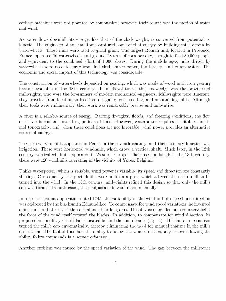
earliest machines were not powered by combustion, however; their source was the motion of waterand wind.
As water flows downhill, its energy, like that of the clock weight, is converted from potential tokinetic. The engineers of ancient Rome captured some of that energy by building mills driven bywaterwheels. These mills were used to grind grain. The largest Roman mill, located in Provence,France, operated 16 waterwheels and ground 28 tons of corn per day, enough to feed 80,000 peopleand equivalent to the combined effort of 1,000 slaves. During the middle ages, mills driven bywaterwheels were used to forge iron, full cloth, make paper, tan leather, and pump water. Theeconomic and social impact of this technology was considerable.
The construction of waterwheels depended on gearing, which was made of wood until iron gearingbecame available in the 18th century. In medieval times, this knowledge was the province ofmillwrights, who were the forerunners of modern mechanical engineers. Millwrights were itinerant;they traveled from location to location, designing, constructing, and maintaining mills. Althoughtheir tools were rudimentary, their work was remarkably precise and innovative.
A river is a reliable source of energy. Barring droughts, floods, and freezing conditions, the flowof a river is constant over long periods of time. However, waterpower requires a suitable climateand topography, and, when these conditions are not favorable, wind power provides an alternativesource of energy.
The earliest windmills appeared in Persia in the seventh century, and their primary function wasirrigation. These were horizontal windmills, which drove a vertical shaft. Much later, in the 12thcentury, vertical windmills appeared in Western Europe. Their use flourished: in the 13th century,there were 120 windmills operating in the vicinity of Ypres, Belgium.
Unlike waterpower, which is reliable, wind power is variable: its speed and direction are constantlyshifting. Consequently, early windmills were built on a post, which allowed the entire mill to beturned into the wind. In the 15th century, millwrights refined this design so that only the mill’scap was turned. In both cases, these adjustments were made manually.
In a British patent application dated 1745, the variability of the wind in both speed and directionwas addressed by the blacksmith Edmund Lee. To compensate for wind speed variations, he inventeda mechanism that rotated the sails about their long axis. This device depended on a counterweight:the force of the wind itself rotated the blades. In addition, to compensate for wind direction, heproposed an auxiliary set of blades located behind the main blades (Fig. 4). This fantail mechanismturned the mill’s cap automatically, thereby eliminating the need for manual changes in the mill’sorientation. The fantail thus had the ability to follow the wind direction; any a device having theability follow commands is a servomechanism.
Another problem was caused by the speed variation of the wind. The gap between the millstones
7

tended to widen with increasing speed. Although more grain could be ground, it was necessaryto increase the force between the stones. The lag governor accomplished this by means of twopendula whose bobs were constrained to swing tangentially to the circle of rotation. Neglecting airresistance, the angle of swing is proportional to angular acceleration. As the angles of the pendulaincreased, a rod connecting the pendula changed the force between the stones. An alternative devicefor controlling the force between the stones was the centrifugal governor, in which the weights swungoutward (Fig. 5). Unlike the lag governor, the swing angle of the weights of the centrifugal governoris proportional to angular rate.
The centrifugal governor used to control the force between the millstones was not a feedback devicefor the simple reason that the speed of the windmill was not affected. To control the speed ofthe blades, Thomas Mead linked a centrifugal governor to a mechanism that furled and unfurledthe windmill’s sails. This feedback controller, which he patented in 1787, was a regulator, since itrejected disturbances (variations in wind speed) to maintain a desired blade speed.
Meanwhile, in 1783, after 18 years of experimentation and development, the Scottish engineerJames Watt (1736-1819) developed a practical steam engine that produced rotary motion. Watt’skey development lay in an improved understanding of thermodynamics; by introducing a separate,cold condenser, he obtained dramatic improvements in power and efficiency. To publicize his engine,Watt and his partner Matthew Boulton (1728-1809) contracted in 1784 to build a massive corn millin London. To oversee construction, they hired John Rennie (1761-1821), a meticulous millwright.Besides supervising the construction of the mill, Rennie introduced a key innovation: he adapted thecentrifugal governor to regulate engine speed. Rennie’s familiarity with centrifugal governors wasdue to the fact that he had trained for two years with one of Scotland’s most famous millwrights,Andrew Meikle (1719-1811). Among Meikle’s innovations, he improved Lee’s method for adjustingthe windmill’s sails by replacing the counterweights with springs.
The centrifugal governor worked well with a lightweight throttle valve developed by Watt. Thecorn mill, while not a financial success, generated valuable publicity for Watt and Boulton in thecompetitive business of steam engines. Their business prospered.
The Watt governor represented a significant advance in technology, since it provided control overenergy. The feedback loop allowed the steam engine to be self regulating. Now the combustionof organic material could be used efficiently to do mechanical work. This ability to exploit largequantities of energy without being subject to the vagaries of the wind allowed machines to operateat power levels that were previously unattainable.
The governor itself became the subject of intense interest, both for its mysterious properties and itscommercial value. The great scientists George Biddell Airy (1801-1892), Charles William Siemens(1823-1883), Leon Foucault (1819-1868), Lord Kelvin (William Thompson) (1824-1907), JamesClerk Maxwell (1831-1879), and Josiah Willard Gibbs (1839-1903) were fascinated by its operation.They sought to improve on the shortcomings in its basic design, such as the lack of integral action
8
(entailing steady-state offset), friction (causing repeated overshoot or hunting), and lack of power(limiting speed of response). These and other improvements were obtained by subsequent engineers;between 1836 and 1902, more than a thousand patents were granted in the United States forgovernors.
The impact of the governor was immense, since every steam engine required one. In addition, thegovernor was used to regulate astronomical equipment, the telegraph, and the phonograph. In 1868,more than 75,000 governors were in use in England. Technological innovation was flourishing andthe Industrial Revolution was under way. The steam engine powered factories, and it moved peopleand goods by means of railroad and ship. Although the steam engine was not suited to flight,feedback control, as we shall now see, was to prove crucial in air transportation.
The Aileron
“Not within a thousand years would man ever fly!”
— Wilbur Wright, recalling in the 1940shis words spoken to his brother Orville in1901 while departing Kitty Hawk for Day-ton. Quoted in Jakab (1990), p. 114.
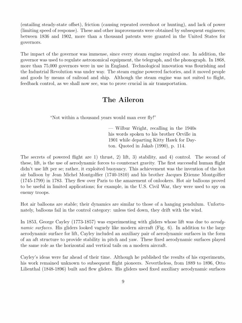
The secrets of powered flight are 1) thrust, 2) lift, 3) stability, and 4) control. The second ofthese, lift, is the use of aerodynamic forces to counteract gravity. The first successful human flightdidn’t use lift per se; rather, it exploited buoyancy. This achievement was the invention of the hotair balloon by Jean Michel Montgolfier (1740-1810) and his brother Jacques Etienne Montgolfier(1745-1799) in 1783. They flew over Paris to the amazement of onlookers. Hot air balloons provedto be useful in limited applications; for example, in the U.S. Civil War, they were used to spy onenemy troops.
Hot air balloons are stable; their dynamics are similar to those of a hanging pendulum. Unfortu-nately, balloons fail in the control category: unless tied down, they drift with the wind.
In 1853, George Cayley (1773-1857) was experimenting with gliders whose lift was due to aerody-
namic surfaces. His gliders looked vaguely like modern aircraft (Fig. 6). In addition to the largeaerodynamic surface for lift, Cayley included an auxiliary pair of aerodynamic surfaces in the formof an aft structure to provide stability in pitch and yaw. These fixed aerodynamic surfaces playedthe same role as the horizontal and vertical tails on a modern aircraft.
Cayley’s ideas were far ahead of their time. Although he published the results of his experiments,his work remained unknown to subsequent flight pioneers. Nevertheless, from 1889 to 1896, OttoLilienthal (1848-1896) built and flew gliders. His gliders used fixed auxiliary aerodynamic surfaces
9

for stability, and he was able to control the motion by shifting his weight. This knowledge camefrom extensive aerodynamic studies of lift and drag as well as experience: he built a symmetric hillfrom which he could glide regardless of the wind direction. Tragically, he died from injuries sufferedwhen his glider stalled and crashed.
During the 19th century, there were numerous enthusiasts interested in the possibility of mannedflight. Many ideas were sketched and few were built, of which fewer met with any success. OctaveChanute (1832-1910) collected an immense amount of information about these ideas and experi-ments. In 1894, he published this material in his book Progress in Flying Machines.
In 1899, the brothers Wilbur Wright (1867-1912) and Orville Wright (1871-1948), who ran a bicy-cle shop in Dayton, Ohio, read Chanute’s book. Two prophetic paragraphs can be found in theConclusions section of Chanute’s book. The first paragraph reads:
If a flying machine were only required to sail at one unvarying angle of incidence incalm air, the problem would be much easier of solution. The center of gravity wouldbe so adjusted as to coincide with the center of pressure at the particular angle of flightdesired, and the speed would be kept as regular as possible; but the flying machine,like the bird, must rise and must fall, and it must encounter whirls, eddies, and gustsfrom the wind. The bird meets these by constantly changing his center of gravity;he is an acrobat, and balances himself by instinct; but the problem is very muchmore difficult for an inanimate machine, and it requires an equipoise—automatic ifpossible—which shall be more stable than that of the bird.
Here Chanute makes an indisputable case for the importance of control. Stability is important, heasserts, but it is not enough; a flying machine must be able to maneuver, and it must be able toreact to disturbances.
Earlier researchers realized this need. Drawings of (sometimes fanciful) aircraft from as early as the1870s show a vertical rudder, presumably inspired by a ship’s rudder. Other drawings show a hori-zontal rudder as well. Unlike the fixed auxiliary surfaces for stability, these surfaces were movable,and they permitted control of the aircraft’s motion. Thus the importance of controlling motionabout multiple axes of rotation was clearly recognized. The second paragraph from Chanute’s bookreads:
The guidance in a vertical direction—i.e., up or down, depends in a great degree uponsuccess in changing the center of gravity which has just been alluded to. It may bepartly effected by changes in the speed or by horizontal rudders, but in such case theequilibrium will be disturbed. Guidance in a horizontal direction has been secured, aswe have seen in several experiments, by vertical rudders; but there are probably othermethods still more effective, although their merits cannot be tested until a practicalapparatus is experimented with. Upon the whole, this problem may give trouble, butit does not seem unsolvable.
10

Within five years of reading these very words, the Wrights demonstrated machine-powered mannedflight. They accomplished this feat with a variety of evolutionary and revolutionary innovations.They adopted the biplane wing structure with truss supports developed by Chanute himself; theysystematically developed a series of gliders with the aid of careful wind tunnel tests; they outfittedtheir gliders with movable aerodynamic surfaces for pitch and yaw control; they invented wingwarping for roll control, which was controlled jointly with yaw control for turning; they builtpowerful, lightweight engines and propellers; and, most importantly, they taught themselves to fly.They were self supporting, and they had little outside assistance aside from correspondence withChanute. In short, they combined the key existing elements of powered flight, and they suppliedthe needed innovations.
The key innovation, which had no clear predecessor, was the use of wing warping to effect lateralcontrol; that is, control for turning (Fig. 7). This innovation provided a full complement of movableaerodynamic surfaces to allow control over all three axes of rotational motion. This innovation wascritical, since it made controlled flight possible.
Wing warping was an innovation that deserved protection. The Wrights patented the technique,which was based on the mechanical coupling of wing warping and vertical rudder deflection. Suchcoupling is needed when turning to counteract adverse yaw, an aerodynamic effect that wouldotherwise cause the airplane to sideslip (not point along its velocity vector) during turning. Butthe Wrights’ patent was soon innovated. In 1908, Glenn Hammond Curtiss (1878-1930), a formermotorcycle racer turned airplane manufacturer, was in direct competition with the Wrights. Histechnique for lateral control did not employ wing warping coupled with rudder deflection; rather,Curtiss used a pair of ailerons, which were operated as separate, movable aerodynamic surfaces.
The idea of using movable aerodynamic surfaces for lateral control arose as early as 1904 in Francefor controlling a glider. In the United States, the idea was suggested in 1908 by Alexander GrahamBell (1847-1922), who, at age 69, was an aviation enthusiast. He suggested the use of movablewing tips for lateral balance control. Casey Baldwin, an associate of Curtiss, implemented aileronsin the form of wing tips on Curtiss’s White Wing aircraft, which he flew in May 1908. The pilotcontrolled the ailerons by means of a shoulder harness; by moving his body, the pilot effected lateralcontrol. Only later was one of the hands freed up for aileron control by using the feet to control theelevator. The word “aileron” derives from the French phrase for “little wings,” reflecting their firstappearance in France. In his 1909 airplane the June Bug, Curtiss mounted the ailerons midwaybetween the biplane wings (Fig. 8). The separation of lateral control from lift was now completein both form and function.
The use of ailerons had two distinct advantages over the Wrights’ patent. First, the ailerons hadthe sole purpose of providing a moment for rolling the aircraft, and their implementation effectivelyseparated lateral control from lift. Consequently, the main wings intended for lift no longer neededto be warped, and therefore could be stiffened. And second, the ailerons were controlled separatelyfrom the rudder to allow independent control of all three axes.
11

In 1905, the Wrights began to use separate hand controls for wing warping and rudder. They didnot protect this variation of their original patent on coupled wing warping and rudder control.Although Curtiss used separate three-axis controls, the Wrights sued him for infringement of theirpatent on coupled rudder and wing warping. In the court’s view, Curtiss’s system for independentthree-axis control infringed on the Wrights’ patent, since coupling of lateral and yaw control isnevertheless essential for turning.
Three-axis rotational control of the aircraft was now complete, and it depended on a complement ofmovable control surfaces, namely, the elevator, the rudder, and the ailerons. This technology alsocompleted the essential elements of flight: thrust, lift, stability, and control. The Age of Aviationhad been ushered in, and transportation and warfare were changed forever. The next step was todevelop devices to assist the pilot in controlling the aircraft as well as the means to venture intospace. To do this required yet another innovation—the gyro.
The Gyro
“. . . if there were no other immortality, you would live forever in that achievement.”
— Helen Keller, in a letter to Elmer Sperrydated February 27, 1930, after a tour ofthe Sperry Gyroscope Company. Quotedin Hughes (1971), p. 321.
“I saw a flock of birds lifting and wheeling in formation as they flew alongside thetrain. Suddenly I saw them as ‘devices’ with excellent vision and extraordinary ma-neuverability. Could they not guide a missile? Was the answer to the problem waitingfor me in my own backyard?”
— B. F. Skinner, describing his inspirationin 1940 for using pigeons for missile guid-ance. Quoted in Capshew (1993), p. 840.
On June 18, 1914, 21-year-old Lawrence Sperry (1893-1924) from Brooklyn, New York, piloted aCurtiss flying machine near Paris in a competition to demonstrate new technology for making flyingsafer. The aircraft carried Sperry and his French mechanic, Emile Cachin. In full view of the judges,Sperry stood up and placed his hands over his head. Cachin then stood up as well and proceededto walk six feet onto the lower wing. Observers expected the plane to roll; instead, they saw theailerons move automatically to maintain level flight (Fig. 9). They had witnessed the all-time mostdramatic demonstration of a feedback control system, as well as a new era in flight.
The key to this success was the practical implementation of a displacement gyroscope, or gyro, whichis a spinning wheel mounted on gimbals. The gyro had been developed by Lawrence’s father Elmer
12

Ambrose Sperry (1860-1930). The spin axis of the wheel maintains its orientation in space as thegimbals rotate around it (Fig. 10). For flight control, the outer gimbal can be aligned with the rollaxis, and the inner gimbal can be aligned with the pitch axis. When disturbances cause the planeto rotate, the gimbal angles provide measurements of the roll and pitch angles of the airplane.
In the system demonstrated in Paris, the gyro was connected to an electrical contact that closeda circuit when the airplane moved out of trim level flight. The electrical contact powered a valvethat released compressed air supplied by the engine. The force of this compressed air moved theelevator and ailerons to bring the airplane back to level flight. In this way, Curtiss’s ailerons andSperry’s gyro formed a feedback loop to stabilize the airplane’s motion.
Aircraft stabilization was not the first application of the gyro, although it was the most importantup to that time. Previously, Elmer Sperry and others had developed gyros for stabilizing automo-biles and ships. In these applications, gyros were used for actuation as well as for sensing. Theactuation was effected by a heavy flywheel that helped suppress roll motion. Although the auto-motive application was unsuccessful, the marine application met with good success on naval vesselsand ocean liners.
An alternative use of a gyro comes in the form of a rate gyro, which determines the angular velocityabout a given axis. A spinning wheel mounted on a single gimbal exerts a torque about an axisthat is perpendicular to the rotation axis. For example, when the base of the gimbal rolls, the gyropitches. This right-angle motion, called precession, is a consequence of the fact that applied torqueinduces a change in angular momentum. This torque can be measured by restraining the gimbalwith a spring and measuring the resulting gimbal angle (Fig. 11).
The development of the gyro for determining angular displacement and angular rates created theability to perform inertial navigation. Inertial navigation refers to navigation without using externalsignals such as radio beacons, magnetic compasses, or optical sightings. Gyrocompasses providethe means to determine heading, while the signals from rate gyros and accelerometers can benumerically integrated to determine location. These devices were essential to the development ofmissile guidance, submarine navigation, and space navigation technology. In addition, feedbackcontrol loops based on gyros have been used in autopilots for pilot assistance or fully autonomousoperation. In short, the gyro opened the door to the Space Age.
The Amplifier
The control technology discussed thus far has been almost entirely mechanical: the escapement ofa clock, the centrifugal governor of a windmill or steam engine, the aileron of an airplane, and thegyro of an aircraft stabilization system. Each of these inventions had a critical effect on the historyof technology. And yet, perhaps the most significant application of feedback control was still to
13
come. As we shall see, there were two distinct developments that shaped the Age of Electronics:the positive-feedback amplifier and the negative-feedback amplifier.
To begin, let us clarify that the amplifier is not inherently a feedback device. In fact, an amplifieris any device that takes an input signal of small amplitude and produces an output signal identicalto the input signal but with larger amplitude. By itself, this is not a surprising feat; a lever placedasymmetrically with respect to a fulcrum is an amplifier. Any movement of the shorter end of thelever will be reproduced by the longer end with a larger amplitude of motion. The lever amplifiesthe arc length of the motion as well as its speed. Similarly, any input force applied to the longerend of the lever will produce an output force of greater magnitude at the shorter end. Thus, a levercan be used to amplify displacement, speed, or force.
Although an amplifier is not inherently a feedback device, it is an essential component of a feedbackcontrol system. The sensor measurements and error signals, which are generally small-amplitude,low-power signals, must ultimately drive actuators that require large power. In the millstone forcecontrol system of a windmill, amplification of the centrifugal-to-millstone force is provided by aseries of levers. Similarly, Elmer Sperry’s aircraft stabilizer used a pneumatic amplifier in whichsmall angular displacements of the gyro gimbals modulated a valve, which released compressed air,and thereby produced large forces for moving the aerodynamic surfaces.
Electrification allowed engineers to operate electrical motors and lighting, but these developmentsdid not depend on amplifiers. However, engineers were also concerned with the transmission ofinformation; specifically, communication by telephone and radio. These technologies required am-plifiers since the signals were weak, and their waveform is of paramount importance. As we shallnow discuss, it was feedback control that was essential to critical developments in each case.
The Positive Feedback Amplifier
“1113149”
— The number of Armstrong’s U.S. patentfor the positive feedback amplifier, as em-blazoned on a flag flown from the aerialtower above his mother’s home in Yonkers,New York, and visible on clear days as faras the Bronx, where Lee de Forest lived.Recounted from Lewis (1991), p. 196.
While experimenting with lamps in 1880, Thomas Alva Edison (1847-1931) observed that a currentcould flow through a vacuum to a metal plate. He had no explanation for this phenomenon, calledthe Edison effect. In fact, only the discovery of the electron would provide a meaningful explanation.
14
Nevertheless, John Ambrose Fleming (1849-1945) studied the Edison effect while employed by theEdison Company in London. There was no immediate application of these studies.
The Edison effect proved to be but one, albeit crucial, step in the development of radio. Thedevelopment of radio went through many phases, from the electromagnetic theories of Maxwell(analyzer of the centrifugal governor) to the spark gap transmitters and receivers of Heinrich Hertz(1857-1894) to the frequency-selective circuits of Oliver Lodge (1851-1940) to the pulsating sparkgap of Guglielmo Marconi (1874-1937). Like all great inventions, the development of radio required along chain of brilliant inventors and scientists. Marconi’s advances, partly achieved by adapting thediscoveries of the great scientists and partly by the accidental discovery of the benefits of grounding,enabled long-distance wireless telegraphy, and became the basis of a new industry. He patentedthese inventions in 1896 when he was 22.
In 1904, Fleming was employed by the Marconi Company, and he returned to his studies of theEdison effect. He made a surprising discovery: an evacuated tube with a filament and plate had theability to rectify ac radio waves. More than a mere curiosity, his diode-rectified telegraph signalscould be heard through headphones. However, since the Marconi Company was interested in crystaldiodes, they did not pursue the development of the tube diode.
Lee de Forest (1873-1961), a young engineer, read of Fleming’s work and began experimenting withtubes. Like his predecessors, he did not understand their operation. But he made a momentousadvance: by including a third wire (the grid) between the filament and plate, he was able to controland amplify the signal applied to the grid. The electronic amplifier was born.
Like all new inventions, this electronic amplifier had limited performance (low gain), and it was notwell understood. Such was the case when Edwin Howard Armstrong (1890-1954) was an undergrad-uate at Columbia University, where he had access to test equipment and triode tubes. Armstronghad been an avid radio hobbyist, and he had considerable experience with radio circuits. Armstrongexperimented extensively with the triode tube, and, in 1912, he built a triode-based amplifier circuitthat had amazingly better performance characteristics than existing amplifiers.
The key to Armstrong’s invention was the use of positive feedback, which he called regeneration.By feeding the audio signal back to the grid, he was able to boost the amplification of the triodecircuit. In effect, the circuit reduced the damping of the oscillations. The amplification was over anarrow band of frequencies, but this was sufficient for radio applications.
Armstrong’s circuit was extremely valuable. Several inventors around the world had developedsimilar circuits, but there was only a single challenger to his patent: de Forest. Years prior, deForest had experimented with a circuit that “howled.” He had virtually no understanding of thecircuit, and he failed to pursue it. Yet his challenge set in motion what is perhaps the most bitterlycontested and lengthy patent litigation case in history. The Wright-Curtiss litigation paled bycomparison. The de Forest-Armstrong regeneration case lasted almost 20 years, and, amazingly, it
15

was decided by the Supreme Court not once, but twice (1928 and 1934). Armstrong lost both times.Nevertheless, the IRE (Institute of Radio Engineers and forerunner of IEEE) awarded Armstrongthe Medal of Honor for what his fellow engineers recognized as truly his invention.
While the ability to produce high gain was the major benefit of his circuit, Armstrong found thatthe positive feedback amplifier offered yet another feature that was critical to the development ofradio. If the gain of the amplifier is sufficiently increased, the circuit oscillates stably; that is, theoscillations can be produced indefinitely without increasing or decreasing in amplitude, and withconstant frequency. The ability to produce stable oscillations is not a mere curiosity; rather, it is anecessary component for modulating and demodulating signals.
The ability to transmit voice and music depended on high-frequency radio communication. Oneapproach to the requisite modulation for transmission was the development of a generator by ErnstAlexanderson (1878-1975) who worked with Charles Proteus Steinmetz (1865-1923) at GE. TheAlexanderson generator weighed many tons, and its spinning disk alone was massive. Yet thismachine succeeded in producing the first broadcast of voice and music. The date was ChristmasEve, 1906. However, the positive-feedback amplifier rendered the Alexanderson generator obsolete;an electronic feedback circuit replaced a massive machine.
The stable oscillations produced by a triode circuit with high-gain positive feedback were laterunderstood to be a result of the nonlinear characteristic of the triode tube. The nonlinear analysis,which was performed by Balthasar van der Pol (1889-1959) (Fig. 12), stands as a classic in nonlineardynamics.
Although many radio circuits had been proposed for demodulating signals, Armstrong’s circuit, thesuperheterodyne, was by far the most successful. This circuit, dating from 1917, incorporated anoscillator for signal demodulation at a frequency located a fixed distance from the incoming signal.The demodulation circuit took a high frequency signal and produced a low-frequency signal thatcould be easily filtered and amplified. This circuit survived the transition from vacuum tubes tosilicon chips.
The Negative Feedback Amplifier
“Black requested permission to work on amplifier design which was granted on thecondition that it did not interfere with his other work.”
— Quoted from Bennett (1993), p. 73.
By 1911, it was possible to place a long-distance call from Boston to Denver; however, there wereserious problems with distortion. Only after amplifier technology improved in the 1930s was long-distance telephone communication truly feasible. The solution to the distortion problem that would
16

improve amplifier technology was as radical as it was classical. Harold Stephen Black (1898-1983),an electrical engineer employed by American Telephone and Telegraph, wrestled with the problemfor a long time. He was especially influenced by a lecture given by Steinmetz in 1923, whereSteinmetz encouraged problem solving based on fundamental principles.
Black realized that he could solve the distortion problem if he could amplify signals with precisegain. Subtracting the suitably scaled (but distorted) output of an amplifier from the input wouldreveal the distortion; amplifying the distortion and subtracting it from the output would leavean undistorted signal. The concept was simple, but it would only work with precise amplifiers.Attempts to set the amplifier gain were invariably useless: drift could occur in a matter of hours.However, on his way to work, one Saturday morning in 1927, as he crossed the Hudson River on aferry, the key idea occurred to him: Use negative feedback to set the gain at a precise, albeit lower,value.
The basis of Black’s circuit was this: Let G denote the open-loop gain of an amplifier, and let kdenote the feedback gain. Then the closed-loop gain G̃ is given by
G̃ =G
1 + kG. (1)
When kG is much larger than 1, this yields
G̃ ≈1
k, (2)
a precise value in spite of uncertainty and drift in G. But making kG much large than 1 makes1/k much less than G. Therefore, this circuit uses negative feedback to reduce the amplifier gain.Fortunately, this reduction was not an obstacle, since amplifiers could be built with extremely large(but usually imprecise) gain.
As simple as this idea was, the patent office treated it with skepticism; nine years passed from patentapplication to granting. On the practical side was the psychological resistance to purposefully low-
ering the gain of an amplifier. On the mathematical side, there were questions about stability. Itwas difficult to understand how stability could hold when the loop gain |kG| was greater than unity;in fact, it was well known that oscillations occurred in high-gain positive-feedback amplifiers. Itfell to Harry Nyquist (1889-1976) to develop a stability theory that accounted for the frequency-dependent gain and phase of a transfer function (at least for stable loop transfer functions; the caseof an unstable loop transfer function was resolved later). Hendrik Wade Bode (1905-1982) eluci-dated the subtleties of amplifier design (limitations and tradeoffs) in subsequent classical research.Ironically, the centrifugal governor and gyro stabilizer had been used for years in negative feedbackloops; however, before the work of Nyquist and Bode, there was little theoretical understanding ofthe frequency-domain ramifications of stability.
AT&T recognized the value of the idea. Working models were built to convince the patent office,and the awarded patent had an astounding 126 claims.
17

The negative feedback amplifier had implications well beyond long-distance telephone communi-cation. William R. Hewlett (1913-2001) studied applications of negative feedback as a graduatestudent at Stanford University. Working with David Packard (1912-1996) in a garage in Palo Alto,Hewlett developed an audio oscillating device for testing sound equipment. Walt Disney Studiosused eight of the devices when they developed the soundtrack for Fantasia. The garage in whichHewlett and Packard worked became a California State Historical landmark, recognized as thebirthplace of Silicon Valley. An official plaque provides a tribute to the impact of feedback controlon modern technology:
BIRTHPLACE OF “SILICON VALLEY” This garage is the birthplace of the world’sfirst high-technology region, “Silicon Valley.” The idea for such a region originatedwith Dr. Frederick Terman, a Stanford University professor who encouraged hisstudents to start up their own electronics companies in the area instead of joiningestablished firms in the East. The first two students to follow his advice were WilliamR. Hewlett and David Packard, who in 1938 began developing their first product, anaudio oscillator, in this garage. California registered historical landmark no. 976.
Conclusions
Is feedback control merely a footnote in the history of technology? In this article I have attemptedto suggest otherwise. The mechanical clock was the most precise and sophisticated machine ofits time; its development had a profound impact on society, and it helped usher in the ScientificRevolution. Although the centrifugal governor was a convenience for operating a windmill, it wasa crucial component of the steam engine and hence of the Industrial Revolution.
The aileron completed the requirements for controlled flight, and it helped to usher in the Age ofAviation. Likewise, the gyro was a crucial component needed for guidance and control in the SpaceAge.
The Electronic Revolution owed much to feedback control. The positive-feedback amplifier providedincreased gain as well as a stable oscillator for modulation and demodulation, essential componentsof radio frequency circuits. The negative-feedback amplifier provided the means to build precisionamplifiers with low distortion. The “trick” of using negative feedback to increase the precision ofan inherently imprecise device was subtle and brilliant, and it was precisely this idea that had madethe steam engine practical and rendered the mechanical clock “better” than its individual parts.
The fact that the invisible technology of feedback control has had such a profound impact onthe history of technology should not be especially surprising. Feedback control has the ability tocombine components into larger, more complex systems with higher precision. An open-loop clockwould be unthinkable.
18

Finally, what does the history of control engineering augur for the future of technology? When thenext great wave of technology washes over civilization (nano/bio/quantum/· · ·), feedback controlwill surely lie at its heart.
Acknowledgments
This article is based on an invited talk I presented at the First NSF Workshop on Ideas and Technology of Control andSystems in High School Math and Science Education, June 27, 2000, Chicago, IL. I am indebted to Prof. B. Pasik-Duncan for the invitation. I also wish to thank Mark Headrick for numerous helpful discussions, Susan Kolovson forencouragement, and Scot and Tammy Osburn for helpful comments. I dedicate this article to my mother, ShorrieBernstein.
References
History of Technology and Engineering
G. Basalla, The Evolution of Technology. Cambridge: Cambridge University Press, 1988.
D.P. Billington, The Innovators: The Engineering Pioneers Who Made America Modern. New York: Wiley, 1996.
R. Burlingame, Scientists Behind the Inventors. New York: Avon, 1960.
J. Brockman, Editor, The Greatest Inventions of the Past 2,000 Years. New York: Simon & Schuster, 2000.
D. Cardwell, Wheels, Clocks, and Rockets: A History of Technology. New York: W.W. Norton & Co., 2001.
C.M. Cipolla, Guns, Sails, and Empires: Technological Innovation and the Early Phases of European Expansion
1400-1700. Manhattan, KS: Sunflower University Press, 1985.
M. Cocker, Rivers of Blood, Rivers of Gold: Europe’s Conquest of Indigenous Peoples. New York: Grove Press, 1998.
T.K. Derry and T.I. Williams, A Short History of Technology from the Earliest Times to A.D. 1900. Oxford: OxfordUniversity Press, 1961. Reprinted by New York: Dover, 1993.
J. Diamond, Guns, Germs, and Steel: The Fates of Human Societies. New York: W.W. Norton & Co., 1997.
E.S. Ferguson, Engineering and the Mind’s Eye. Cambridge: MIT Press, 1994.
F. Gies and J. Gies, Cathedral, Forge, and Waterwheel: Technology and Invention in the Middle Ages. New York:HarperCollins, 1995.
D.R. Headrick, The Tools of Empire. New York: Oxford University Press, 1981.
D. Hill, A History of Engineering in Classical and Medieval Times. London: Routledge, 1996.
E.J. Hobsbawm, Industry and Empire: From 1750 to the Present Day. New York: The New Press, 1999.
K.S. Kirby et al., Engineering in History. New York: McGraw-Hill, 1956. Reprinted by New York: Dover, 1990.
W.H. McNeill, The Pursuit of Power. Chicago: University of Chicago Press, 1982.
J. Mokyr, The Lever of Riches: Technological Creativity and Economic Progress. New York: Oxford UniversityPress, 1990.
19

L. Mumford, Technics and Civilization. San Diego: Harcourt Brace & Co., 1963.
L. Mumford, The Myth and the Machine: I Technics and Human Development. San Diego: Harcourt Brace & Co.,1967.
L. Mumford, The Myth and the Machine: II The Pentagon of Power. San Diego: Harcourt Brace & Co., 1970.
A.W.J.G. Ord-Hume, Perpetual Motion: The History of an Obsession. New York: St. Martin’s Press, 1977.
C. Pursell, The Machine in America: A Social History of Technology. Baltimore: Johns Hopkins University Press,1995.
R.S. Shelton et al., Engineering in History. New York: Dover, 1990.
D.L. Spar, Ruling the Waves. New York: Harcourt, Inc., 2001.
A.P. Usher, A History of Mechanical Inventions (rev. ed.). Cambridge: Harvard University Press, 1954. Reprintedby New York: Dover, 1988.
S. Vogel, Cats’ Paws and Catapults: Mechanical Worlds of Nature and People. New York: Norton, 1998.
N. Wiener, Invention: The Care and Feeding of Ideas. Cambridge: MIT Press, 1994.
History of Control Engineering
B.D.O. Anderson, “Control Engineering as an Integrating Discipline From the 17th To the 21st Century,” Int. J.
Soc. Materials Engineering for Resources, vol. 1, pp. 10-26, 1991.
D.M. Auslander, “Evolutions in automatic control,” Trans. ASME J. Dyn. Sys. Meas. Contr., vol. 93, pp. 4-9,1971.
R. Bellman, Eye of the Hurricane: An Autobiography. Singapore: World Scientific, 1984.
S. Bennett, A History of Control Engineering 1800-1930. London: Peter Peregrinus Ltd., 1979.
S. Bennett, A History of Control Engineering 1930-1955. London: Peter Peregrinus Ltd., 1993.
Editors of Scientific American, Automatic Control. New York: Simon and Schuster, 1955.
A.T. Fuller, “The early development of control theory,” ASME J. Dyn. Sys. Meas. Contr., vol. 98, pp. 109-118,June 1976.
A.T. Fuller, “The early development of control theory II,” ASME J. Dyn. Sys. Meas. Contr., vol. 98, pp. 224-235,September 1976.
K. Kelly, Out of Control. Reading: Addison-Wesley, 1994.
L. Maunder, Machines in Motion. Cambridge: Cambridge University Press, 1986.
O. Mayr, The Origins of Feedback Control. Cambridge: MIT Press, 1970.
O. Mayr, Authority, Liberty, & Automatic Machinery in Early Modern Europe. Baltimore: Johns Hopkins UniversityPress, 1986.
N. Wiener, Cybernetics: Or Control and Communication in the Animal and the Machine, (2nd ed.). Cambridge:MIT Press, 1961.
N. Wiener, The Human Use of Human Beings: Cybernetics and Society. Boston: Houghton Mifflin, 1954; Reprintedby New York: Da Capo Press, 1988.
20

Clocks
G.B. Airy, “On the disturbances of pendulums and balances, and on the theory of escapements,” Trans. Cambridge
Phil. Soc., vol. III, part 1, pp. 105-128, 1830.
W.J.H. Andrewes, Ed., The Quest for Longitude (2nd. ed.). Cambridge: Harvard University, Collection of HistoricalScientific Instruments, 1998.
A.A. Andronov, A.A. Vitt, and S.E. Khaikin, Theory of Oscillators. Oxford: Pergamon Press, 1966. Reprinted byNew York: Dover, 1987.
J.E. Barnett, Time’s Pendulum: From Sundials to Atomic Clocks, the Fascinating History of Timekeeping and How
Our Discoveries Changed the World. San Diego: Harcourt Brace, 1998.
F.J. Britton, The Escapements: Their Action, Construction, and Proportion. Chicago: Hazlitt, undated. Reprintedby Arlington: Arlington Books, 1984.
C.M. Cipolla, Clocks and Culture 1300-1700. New York: Norton, 1978.
G. Dohrn-van Rossum, History of the Hour: Clocks and Modern Temporal Orders. Chicago: University of ChicagoPress, 1996.
H.B. Fried, The Watch Escapement. New York: Columbia Communications, 1974.
W.J. Gazely, Clock and Watch Escapements. London: Heywood, 1956.
F. Gies and J. Gies, Cathedral, Forge, and Waterwheel: Technology and Invention in the Middle Ages. New York:Harper Perennial, 1994.
J. Gimpel, The Medieval Machine: The Industrial Revolution of the Middle Ages. New York: Penguin Books, 1976.
C. Schwartz and R. Gran, “Describing function analysis using MATLAB,” Contr. Sys. Mag., vol. 21, pp. 19-26,August 2001.
M.V. Headrick, Clock and Watch Escapement Mechanics. Unpublished, 1997.
L. Jardine, Ingenious Pursuits: Building the Scientific Revolution. New York: Doubleday, 1999.
M. Kesteven, “On the mathematical theory of clock escapements,” Amer. J. Physics, vol. 46, no. 2, pp. 125-129,1978.
D.S. Landes, Revolution in Time: Clocks and the Making of the Modern World (rev. ed.), Cambridge: HarvardUniversity Press, 2000.
A.M. Lepschy, G.A. Mian, and U. Viaro, “Feedback control in ancient water and mechanical clocks,” IEEE Trans.
Educ., vol. 35, no. 1, pp. 3-10, 1992.
R. Levine, A Geography of Time. New York: Basic Books, 1997.
H.A. Lloyd, Some Outstanding Clocks over Seven Hundred Years 1250-1950. London: Leonard Hill, 1958.
K. Maurice and O. Mayr, The Clockwork Universe: German Clocks and Automata, 1550-1650. Washington, D.C.:Smithsonian Institution, 1980.
J.C. Pellaton, Watch Escapements (3rd. ed.). London: NAG Press, undated.
L. Penman, Practical Clock Escapements. Shingle Springs: Clockworks Press Int., 1998.
J.H. Reid, “The measurement of time,” J. Royal Astronomical Soc. Canada, vol. 66, no. 3, pp. 135-148, 1972.
21

A. Roup and D.S. Bernstein, “On the dynamics of the escapement mechanism of a mechanical clock,” Proc. Conf.
Dec. Contr., Phoenix, AZ, December 1999, pp. 2599-2604.
A.V. Roup, D.S. Bernstein, S.G. Nersesov, W.M. Haddad, and V. Chellaboina, “Limit cycle analysis of the vergeand foliot clock escapement using impulsive differential equations and Poincare maps,” Proc. Amer. Contr. Conf.,Arlington, VA, June 2001, pp. 3245-3250
D. Sobel and W.J.H. Andrewes, The Illustrated Longitude: The True Story of a Lone Genius Who Solved the Greatest
Scientific Problem of His Time. New York: Walker and Co., 1998.
C. Sturridge, Director, Longitude, DVD or VHS, August 2000.
J.E.D. Williams, From Sails to Satellites: The Origin and Development of Navigational Science. New York: OxfordUniversity Press, 1992.
Governors
D.M. Auslander, “The computer as liberator: The rise of mechanical system control,” Trans. ASME J. Dyn. Sys.
Meas. Contr., vol. 115, pp. 234-238, 1993.
C.T.G. Boucher, John Rennie 1761-1821, The Life and Work of a Great Engineer. Manchester: Manchester Univer-sity Press, 1963.
T.A. Edison, “Centrifugal Speed Governor,” U.S. Patent 1,583,783.
S. Freese, Windmills and Millwrighting. South Brunswick: Great Albion Books, 1971.
A.T. Fuller, “Maxwell’s treatment of governors fitted with differential gears,” Int. J. Contr., vol. 65, pp. 385-408,1996.
A.T. Fuller, “Maxwell’s treatment of Siemens’s hydraulic governor,” Int. J. Contr., vol. 60, pp. 861-884, 1994.
R.L. Hills, Power from Steam. Cambridge: Cambridge University Press, 1989.
R.L. Hills, Power from Wind: A History of Windmill Technology. Cambridge: Cambridge University Press, 1994.
B. Hindle and S. Lubar, Engines of Change: The American Industrial Revolution 1790-1860. Washington, D.C.:Smithsonian Institution Press, 1986.
O. Mayr, Feedback Mechanisms in the Historical Collections of the National Museum of History and Technology.Washington, D.C.: Smithsonian Institution Press, 1971.
O. Mayr, “Victorian physicists and speed regulation: An encounter between science and technology.” Notes and
Records of the Royal Society of London, vol. 26, pp. 205-228, 1971.
O. Mayr, “James Clerk Maxwell and the origins of cybernetics,” Isis, vol. 62, pp. 425-444, 1971.
O. Mayr, “Yankee practice and engineering theory: Charles T. Porter and the dynamics of the high speed steamengine,” Technology and Culture, vol. 16, pp. 570-602, 1975.
M. Watts, “The Rise of the Governor,” Trans. International Molinological Soc. vol. 6, pp. 337-348, 1985.
Ailerons
M.J. Abzug and E.E. Larrabee, Airplane Stability and Control: A History of the Technologies That Made Aviation
Possible. Cambridge: Cambridge University Press, 1997.
22

J.D. Anderson, Jr., A History of Aerodynamics. Cambridge: Cambridge University Press, 1998.
J.D. Anderson, Introduction to Flight (4th ed.), New York: McGraw-Hill, 2000.
R.H. Barnard and D.R. Philpott, Aircraft Flight (2nd ed.). Essex: Longman, 1995.
W. Boyne et al., Flight. Alexandria: Time-Life Books, 1990.
R.V. Bruce, Bell: Alexander Graham Bell and the Conquest of Solitude. Ithaca: Cornell University Press, 1973.
O. Chanute, Progress in Flying Machines. New York: Dover, 1997.
T. Crouch, The Bishop’s Boys: A Life of the Wright Brothers. New York: Norton, 1989.
S. Dalton, The Miracle of Flight. Buffalo: Firefly Press, 1999.
M. Grosser, Gossamer Odyssey: The Triumph of Human-Powered Flight. New York: Dover, 1991.
F. Howard, Wilbur and Orville: A Biography of the Wright Brothers. Mineola: Dover, 1987.
P.L. Jakab, Visions of a Flying Machine: The Wright Brothers and the Process of Invention. Washington, D.C.:Smithsonian Institution Press, 1990.
F.G. Kelly, The Wright Brothers. New York: Dover, 1989.
B.R. Rich and L. Janos, Skunk Works. Boston: Little, Brown, and Co., 1994.
C.R. Roseberry, Glenn Curtiss: Pioneer of Flight. Syracuse: Syracuse University Press, 1972.
D. Stinton, The Anatomy of the Airplane (2nd ed.). Washington, D.C.: AIAA, 1998.
J. Stoff, Picture History of Early Aviation, 1903-1913. New York: Dover, 1996.
H. Tennekes, The Simple Science of Flight: From Insects to Jumbo Jets. Cambridge: MIT Press, 1997.
W.G. Vincenti, What Engineers Know and How They Know It: Analytical Studies from Aeronautical History. Bal-timore: Johns Hopkins University Press, 1990.
P.P. Wegener, What Makes Airplanes Fly? History, Science and Applications of Aerodynamics, (2nd ed.). New York:Springer, 1997.
O. Wright, How We Invented the Airplane. New York: Dover, 1953.
C. Yeager and L. Janos, Yeager. New York: Bantam Books, 1985.
Gyros
J. H. Capshew, “Engineering behavior: Project Pigeon, World War II, and the conditioning of B.F. Skinner,”Technology and Culture, vol. 34, pp. 835-857, 1993.
P.E. Ceruzzi, Beyond the Limits: Flight Enters the Computer Age. Cambridge: MIT Press, 1989.
R.F. Deimel, Mechanics of the Gyroscope: The Dynamics of Rotation. New York: Macmillan, 1929. Reprinted byNew York: Dover, 1950.
E.S. Ferry, Applied Gyrodynamics. New York: Wiley, 1932.
G. Greenhill, Gyroscopic Theory. Bronx: Chelsea, 1966.
T.P. Hughes, Elmer Sperry: Inventor and Engineer. Baltimore: Johns Hopkins University Press, 1971.
23

C. Machover, Basics of Gyroscopes. New York: Rider, 1960.
D. Mackenzie, Inventing Accuracy: A Historical Sociology of Nuclear Missile Guidance. Cambridge: MIT Press,1990.
S. Merhav, Aerospace Sensor Systems and Applications. New York: Springer, 1996.
J. Perry, Spinning Tops and Gyroscopic Motion. New York: Dover, 1957.
K.I.T. Richardson, The Gyroscope Applied. New York: The Philosophical Library, 1954.
P.H. Savet, Ed., Gyroscopes: Theory and Design. New York: McGraw-Hill Book Co., 1961.
J.B. Scarborough, The Gyroscope, Theory and Applications. New York: Interscience, 1958.
W.T. Thomson, Introduction to Space Dynamics. New York: Dover, 1961.
J. Walker, Roundabout: The Physics of Rotation in the Everyday World. New York: W.H. Freemand and Co., 1985.
The Positive-Feedback Amplifier
H.G.J. Aitken, Syntony and Spark: The Origins of Radio. New York: Wiley, 1976.
H.G.J. Aitken, The Continuous Wave: Technology and American Radio, 1900-1932. Princeton: Princeton UniversityPress, 1985.
H. Bremmer and C.J. Bouwkamp, Balthasar van der Pol: Selected Scientific Papers. Amsterdam: North-HollandPublishing Company, 1960.
J.E. Brittain, Alexanderson. Baltimore: The Johns Hopkins University Press, 1992.
J.Z. Buchwald, The Creation of Scientific Effects: Heinrich Hertz and Electric Waves. Chicago: The University ofChicago Press, 1994.
R. Conot, Thomas A. Edison: A Streak of Luck. New York: Seaview, 1979. Reprinted by New York: Da CapoPress, 1986.
S.J. Douglas, Inventing American Broadcasting 1899-1922. Baltimore: The Johns Hopkins University Press, 1987.
P. Israel, Edison: A Life of Invention. New York: Wiley, 1998.
J. Jespersen and J. Fitz-Randolph, From Sundials to Atomic Clocks: Understanding Time and Frequency (2nd ed.).Mineola: Dover, 1999.
R.R. Kline, Steinmetz: Engineer and Socialist. Baltimore: The Johns Hopkins University Press, 1992.
L. Lessing, Man of High Fidelity: Edwin Howard Armstrong. New York: Bantam Books, 1969.
T.S.W. Lewis, Empire of the Air: The Men Who Made Radio. New York: HarperCollins, 1991.
D. Marconi, My Father, Marconi. Toronto: Guernica, 1996.
P.J. Nahin, The Science of Radio. Woodbury: American Institute of Physics, 1996.
J.M. Thomas, Michael Faraday and the Royal Institution: The Genius of Man and Place. Bristol: Adam Hilger,1991.
D.G. Tucker, “The history of positive feedback: The oscillating audion, the regenerative receiver, and other applica-tions up to around 1923,” The Radio and Electronic Engineer, vol. 42, no. 2, pp. 69-80, 1972.
24

B. van der Pol, “A theory of the amplitude of free and forced triode vibrations,” The Radio Review, vol. I, pp.701-762, Nov. 1920.
The Negative-Feedback Amplifier
H.S. Black, “Stabilized feed-back amplifiers,” Electrical Engineering, vol. 53, no. 1, pp. 114-120, 1934. Reprinted inProc. IEEE, vol. 87, no. 2, pp. 379-385, 1999.
H.S. Black, “Stabilized feedback amplifiers,” Bell Sys. Tech. J., vol. 13, no. 3, pp. 1-18, 1934.
H.S. Black, “Inventing the negative feedback amplifier,” IEEE Spectrum, pp. 54-60, 1977.
H.W. Bode, “Obituary statement: Harry Nyquist,” IEEE Trans. Autom. Contr., vol. AC-22, pp. 897-898, 1977.
H.W. Bode, “Relations between attenuation and phase in feedback amplifier design,” Bell Sys. Tech. J., vol. 19, no.3, pp. 421-446, 1940.
B. Friedland, “Introduction to ‘Stabilized feed-back amplifiers,’” Proc. IEEE, vol. 87, no. 2, pp. 376-378, 1999.
P.J. Nahin, Oliver Heaviside, Sage in Solitude. New York: IEEE Press, 1988.
M.E. Van Valkenburg, “In memoriam: Hendrik W. Bode,” IEEE Trans. Autom. Contr., vol. AC-29, pp. 193-194,1984.
I. Yavetz, From Obscurity to Enigma: The Work of Oliver Heaviside, 1872-1889. Basel: Birkhauser, 1995.
25

Figures
Figure 1. The verge and foliot was the earliest clock escapement. Developed in the late 13th century, it remainedunchanged until the 17th century.
Figure 2. The first pendulum clock was developed by Huygens in 1657. This escapement was based on a verge andfoliot with the foliot replaced by a pendulum. (Barnett (1998), p. 89, reproduced with permission.)
Figure 3. The anchor escapement, which appeared in 1671, had an escape wheel and an escape lever that moved ina single plane. The escape lever is attached to a pendulum, and the escape wheel is attached to the hanging weightand clockwork. This compact design had many subsequent variations and, since the escape lever moves through onlya few degrees of arc, was considerably more precise than the verge-and-foliot escapement. (Barnett (1998), p. 90,reproduced with permission.)
Figure 4. The fantail mechanism of a windmill was a conspicuous use of feedback. This auxiliary set of blades reactedto the direction of the wind to turn the windmill so that the main set of blades faced directly into the wind.(Freese(1971), p. 18, reproduced with permission.)
Figure 5. The centrifugal governor was used to regulate the force between the millstones. The spinning weights,which respond to centrifugal force, are connected to a series of linkages that increase the force between the stonesat higher speeds. This is not a feedback mechanism, since there is no closed loop. However, a later patent by Meadused the centrifugal governor to furl and unfurl the cloth that covers the blades, thus using feedback to maintain adesired speed. (Freese (1971), p. 52, reproduced with permission.)
Figure 6. George Cayley’s aircraft designs used aerodynamic surfaces for lift as well as stability. In 1853, he built aglider that successfully carried a person. (Anderson (2000), p. 11, reproduced with permission.)
Figure 7. The Wrights’ key invention was the use of wing warping to effect lateral control. This innovation provideda full complement of movable aerodynamics surfaces to allow control over all three axes of rotational motion. (Wright(1953), p. 14, reproduced with permission.)
Figure 8. In 1908, Glenn Curtiss flew his Gold Bug airplane, which used ailerons mounted between the biplanewings to effect lateral control. This innovation separated lateral control from lift, but was close enough in spiritto wing warping to entail a bitter patent battle with the Wrights. (Roseberry (1972), Figure 39, reproduced withpermission.)
Figure 9. In the first public demonstration of gyroscopic stabilization, Lawrence Sperry, son of engineer ElmerSperry, removes his hands from the controls while his mechanic, Emile Chardin, walks onto the lower wing. Thisdemonstration occurred near Paris during a 1914 competition on innovative aircraft safety features. (Hughes (1971),p. 196, reproduced with permission.)
Figure 10. A displacement gyro is a spinning wheel mounted on a pair of gimbals. The spin axis of the wheelmaintains its orientation in space as the gimbals rotate. By aligning the outer gimbal with the roll axis and theinner gimbal with the pitch axis, it is possible to measure these angles during flight. (Machover (1960), p. 1—3,reproduced with permission.)
26

Figure 11. A rate gyro uses precession to measure angular rate about a desired axis. By aligning the gimbal axis withthe roll axis, a pitch rotation rate will produce a torque on the gimbal. This torque can be measured by restrainingthe gimbal by a spring and measuring the gimbal angle. (Machover (1960), p. 2—2, reproduced with permission.)
Figure 12. This positive-feedback circuit with the transformer output connected to the triode grid produces sustainedoscillations that can be used for radio signal modulation and demodulation. The governing equation is known as thevan der Pol oscillator.
27