Embed Size (px)
Citation preview
FIG Apparatus Norms Parts I - III June 2018
FÉDÉRATION INTERNATIONALE
DE GYMNASTIQUE
FIG Apparatus Norms
FIG Apparatus Norms Parts I - III June 2018
FÉDÉRATION INTERNATIONALE
DE GYMNASTIQUE
Apparatus Norms
FIG Apparatus Norms Parts I - III June 2018
Editorial In its commitment to serve its partners and performers ever better at the international competition level, the International Federation of Gymnastics (FIG) is exceptionally pleased to introduce the new edition of the Apparatus Norms for gymnastics. This publication is based on the revision of the 2017 edition and has been in effect since 01.06.2017. This document is the result of a team effort led by the members of the FIG Apparatus Commission in close cooperation with the concerned Technical Committees and both the Scientific and Medical Commissions. Mr. Ludwig Schweizer of the University of Freiburg (Germany), Director of the FIG Apparatus Testing Institute has managed the editing process. The new contents of this FIG Apparatus Manual offer a didactical approach, which allows the readers to learn about the particular functions of each apparatus and about the intricate process that surrounds certification and approval. This publication also serves as a source of official information for all National Federations and lays the foundation of the collaboration between the FIG and the apparatus manufacturers. The new concept of these regulations’ layout makes it possible to update the specific data pertaining to each apparatus used in the various gymnastic disciplines. It allows the technicians, the organizers, and above all the apparatus manufacturers to be kept abreast immediately on the latest developments in this important area. The drafting of these norms has taken into consideration our Technical Regulations, Codes of Points and Media Regulations. With this publication, the FIG is renewing its commitment to the absolute necessity of providing standards for the apparatus used in official events and to guaranteeing that consistent testing and certification procedures are provided by fully neutral institutes delivering certificates in due form. In this respect, the FIG is pleased to further contribute to the improvement of our gymnasts’ safety and to remain vigilant about fair play in competition. We wish to thank everyone who has contributed to the publication of this document. The FIG wishes to all of them much success and a prosperous future at the service of the gymnasts and their managers. With our compliments, INTERNATIONAL FEDERATION OF GYMNASTICS Morinari Watanabe André Gueisbuhler Ali Al-Hitmi President Secretary General Apparatus Commission President
FIG Apparatus Norms Parts I - III June 2018
Division of chapters
I General part II Apparatus Norms III Certificates and diplomas Appendix Impressum IV Testing procedures
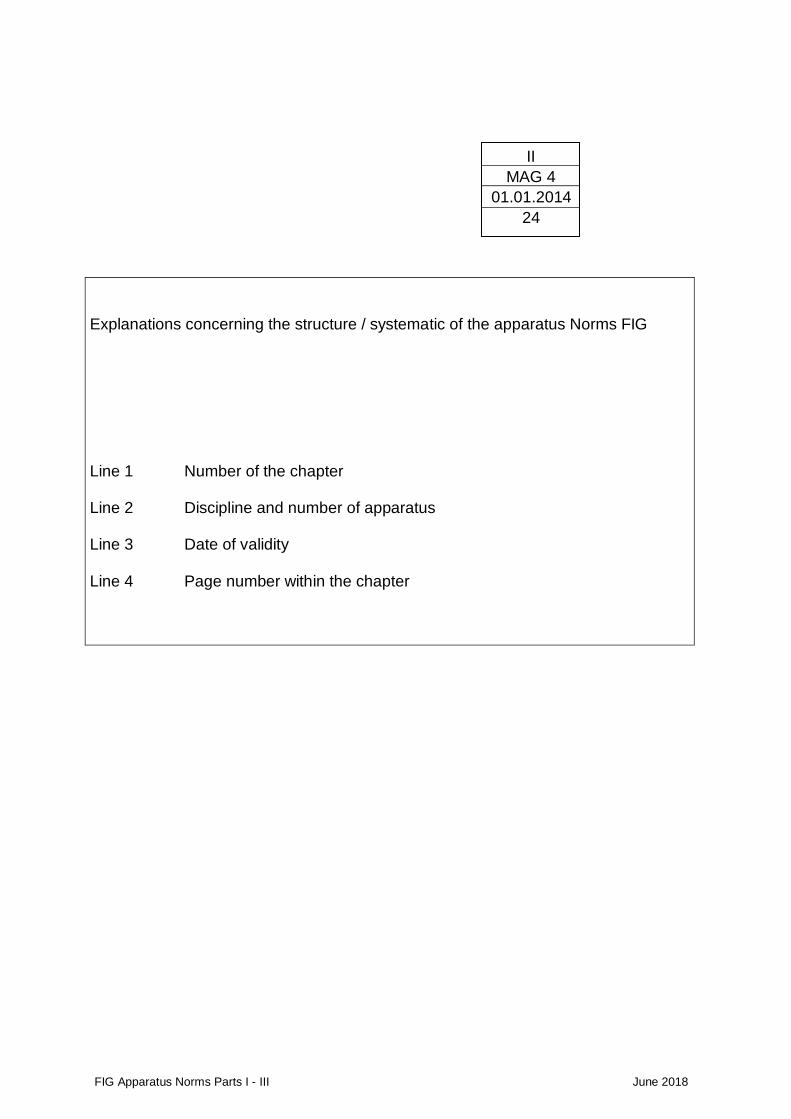
FIG Apparatus Norms Parts I - III June 2018
Explanations concerning the structure / systematic of the apparatus Norms FIG Line 1 Number of the chapter Line 2 Discipline and number of apparatus Line 3 Date of validity Line 4 Page number within the chapter
II
MAG 4
01.01.2014
24

FIG Apparatus Norms Parts I - III June 2018
FÉDÉRATION INTERNATIONALE
DE GYMNASTIQUE
I General Part
Content
FIG Apparatus Norms Parts I - III June 2018
I
01.01.2009
11
Page
1. Introduction / Layout
2. Purpose and Principles I/3
3. Validity of the Apparatus Norms I/4
4. Guarantee for quality I/5
FIG Apparatus Norms Parts I - III June 2018
I
01.01.2018
3
1. Introduction / Layout
The present booklet has four parts.
PART I. is the general part and contains the aim of these Rules, the introduction, the layout and general principles.
Part I is aimed at all users. PART II. contains the actual Apparatus Norms with drawings,
measurements, description of functional properties and testing norms.
Part II is also aimed at all users. PART III. contains the procedures for how to obtain FIG Certificates and
Diplomas. Part III is mainly oriented to the apparatus manufacturers. PART IV. contains the detailed description of the testing procedures and is
directed to the apparatus manufacturers and the FIG recognised Testing Institutes.
2. Purpose and Principles
• The purpose of these Apparatus Norms is first, to have equivalent apparatus at all competitions. It is essential for the competitors to have the same, optimal conditions for the preparations for competitions and at competitions all over the World. This is necessary for practical reasons, for competition fairness and comparison and for safety.
• All apparatus used at official FIG events; the Olympic Games and the World Games must have a valid FIG Certificate. This Certificate will be issued by the FIG, provided the apparatus has been tested successfully.
• The controlled certification by the FIG and the testing procedures guarantee, that the Apparatus Norms are respected. With the Diplomas issued by the FIG, a partnership between the FIG and the apparatus manufacturers is created.
FIG Apparatus Norms Parts I - III June 2018
I
01.01.2018
4
• The choice of material and construction must be left to the manufacturers, to allow the apparatus to adapt to progress, development and new construction techniques. Therefore, the FIG only prescribes measurements, functional properties, norms for testing and testing procedures.
• The FIG recognises neutral Testing Institutes, which have to follow the testing procedures decided by the FIG to test the functional properties, the norms and measurements of the apparatus.
• The testing procedures must be constantly developed with the purpose to have meaningful testing procedures for all apparatus and further develop existing procedures. It is important to develop testing procedures which guarantee, that the apparatus fulfil the norms also after intensive use.
• To enforce the Apparatus Norms and to guarantee the quality of apparatus after intensive use, the FIG may, before, during or after an event, control the apparatus and make re-tests at the Testing Institute.
• In case of contradictions between the Apparatus Norms and the Code of Points, the Apparatus Norms prevail.
3. Validity of the Apparatus Norms FIG Certificate compulsory for all Apparatus These Apparatus Norms were decided by the FIG Executive Committee and
are valid from 1st January 2018. They replace all previous editions as well as all previous decisions and
publications regarding apparatus norms from the Executive Committee, Technical Committees and the Apparatus Commission of the FIG.
They are compulsory for all FIG events, as well as at the Olympic Games, World Games, Commonwealth Games, Asian Games, Pan-American Games, University Games and other multi-sport Games with International participation. At all those events, no apparatus which does not have a valid FIG Certificate may be used.
The FIG strongly recommends that at all other national and international events, organised independently by its member federations or unions, only apparatus which have a valid FIG Certificate may be used.
At international events, apparatus without a valid FIG Certificate may only be used provided all participating member federations have agreed in writing and bear the full responsibility and liability for the use of such uncertified apparatus. The FIG waives all responsibility in the cases where apparatus without a valid FIG Certificate are used.
FIG Apparatus Norms Parts I - III June 2018
I
01.01.2018
5
4. Guarantee for quality To guarantee equal quality and fairness for the competitors and to guarantee
their safety and health, testing procedures for the quality of apparatus are necessary. Those testing procedures are defined in the Apparatus Norms part II and IV.
These apparatus norms as well as the requested norms and functional properties must not only be fulfilled at the time of the test at the Testing Institute. The apparatus manufacturers must guarantee to produce their apparatus in such a quality that the apparatus also fulfil the requested norms, functional properties and safety aspects after intensive use e.g. after a World Championship.
FIG Apparatus Norms Parts I - III June 2018
FÉDÉRATION INTERNATIONALE
DE GYMNASTIQUE
II Apparatus Norms
Content
FIG Apparatus Norms Parts I - III June 2018
II
01.06.2018
2
Page
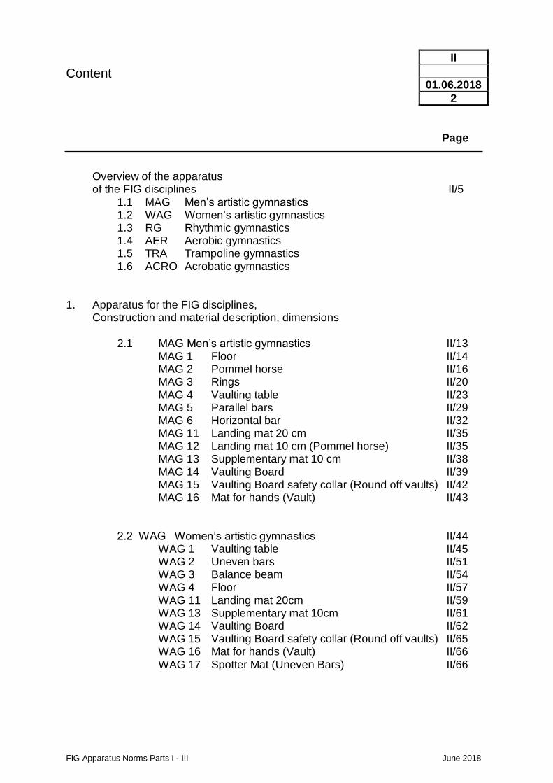
Overview of the apparatus of the FIG disciplines II/5
1.1 MAG Men’s artistic gymnastics 1.2 WAG Women’s artistic gymnastics 1.3 RG Rhythmic gymnastics 1.4 AER Aerobic gymnastics 1.5 TRA Trampoline gymnastics 1.6 ACRO Acrobatic gymnastics
1. Apparatus for the FIG disciplines,
Construction and material description, dimensions
2.1 MAG Men’s artistic gymnastics II/13 MAG 1 Floor II/14 MAG 2 Pommel horse II/16 MAG 3 Rings II/20 MAG 4 Vaulting table II/23 MAG 5 Parallel bars II/29 MAG 6 Horizontal bar II/32 MAG 11 Landing mat 20 cm II/35 MAG 12 Landing mat 10 cm (Pommel horse) II/35 MAG 13 Supplementary mat 10 cm II/38 MAG 14 Vaulting Board II/39 MAG 15 Vaulting Board safety collar (Round off vaults) II/42 MAG 16 Mat for hands (Vault) II/43
2.2 WAG Women’s artistic gymnastics II/44 WAG 1 Vaulting table II/45 WAG 2 Uneven bars II/51 WAG 3 Balance beam II/54 WAG 4 Floor II/57 WAG 11 Landing mat 20cm II/59 WAG 13 Supplementary mat 10cm II/61 WAG 14 Vaulting Board II/62 WAG 15 Vaulting Board safety collar (Round off vaults) II/65 WAG 16 Mat for hands (Vault) II/66 WAG 17 Spotter Mat (Uneven Bars) II/66
Content
FIG Apparatus Norms Parts I - III June 2018
II
01.06.2018
3
Page
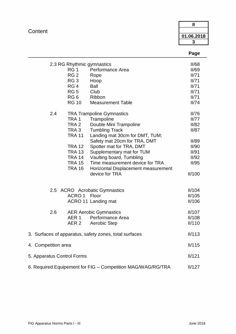
2.3 RG Rhythmic gymnastics II/68 RG 1 Performance Area II/69 RG 2 Rope II/71 RG 3 Hoop II/71 RG 4 Ball II/71 RG 5 Club II/71 RG 6 Ribbon II/71 RG 10 Measurement Table II/74
2.4 TRA Trampoline Gymnastics II/76 TRA 1 Trampoline II/77 TRA 2 Double Mini Trampoline II/82 TRA 3 Tumbling Track II/87 TRA 11 Landing mat 30cm for DMT, TUM; Safety mat 20cm for TRA, DMT II/89 TRA 12 Spotter mat for TRA, DMT II/90 TRA 13 Supplementary mat for TUM II/91 TRA 14 Vaulting board, Tumbling II/92 TRA 15 Time measurement device for TRA II/95 TRA 16 Horizontal Displacement measurement
device for TRA II/100 2.5 ACRO Acrobatic Gymnastics II/104 ACRO 1 Floor II/105 ACRO 11 Landing mat II/106 2.6 AER Aerobic Gymnastics II/107 AER 1 Performance Area II/108 AER 2 Aerobic Step II/110
3. Surfaces of apparatus, safety zones, total surfaces II/113 4. Competition area II/115 5. Apparatus Control Forms II/121 6. Required Equipement for FIG – Competition MAG/WAG/RG/TRA II/127
FIG Apparatus Norms Parts I - III June 2018
II
01.01.2017
5
1 Overview of the apparatus of the FIG disciplines
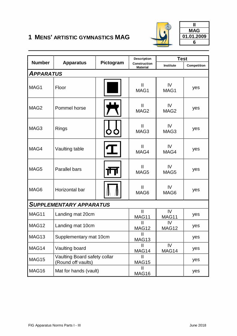
1 MENS' ARTISTIC GYMNASTICS MAG
FIG Apparatus Norms Parts I - III June 2018
II
MAG
01.01.2009
6
Number Apparatus Pictogram Description Test
Construction Material
Institute Competition
APPARATUS
MAG1 Floor
II MAG1
IV MAG1
yes
MAG2 Pommel horse
II MAG2
IV MAG2
yes
MAG3 Rings
II MAG3
IV MAG3
yes
MAG4 Vaulting table
II MAG4
IV MAG4
yes
MAG5 Parallel bars
II MAG5
IV MAG5
yes
MAG6 Horizontal bar
II MAG6
IV MAG6
yes
SUPPLEMENTARY APPARATUS
MAG11 Landing mat 20cm II
MAG11 IV
MAG11 yes
MAG12 Landing mat 10cm II
MAG12 IV
MAG12 yes
MAG13 Supplementary mat 10cm II
MAG13 yes
MAG14 Vaulting board II
MAG14 IV
MAG14 yes
MAG15 Vaulting Board safety collar (Round off vaults)
II MAG15
yes
MAG16 Mat for hands (vault) II
MAG16 yes
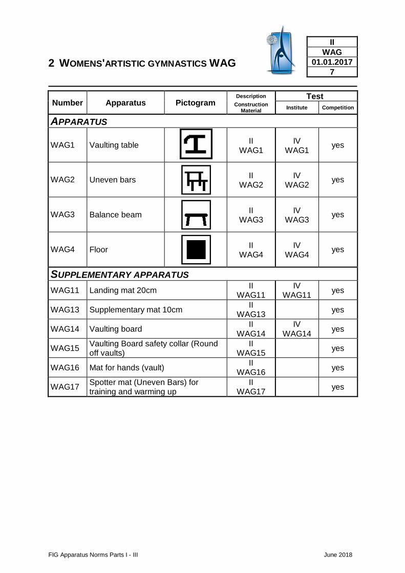
2 WOMENS'ARTISTIC GYMNASTICS WAG
FIG Apparatus Norms Parts I - III June 2018
II
WAG
01.01.2017
7
Number Apparatus Pictogram Description Test
Construction Material
Institute Competition
APPARATUS
WAG1 Vaulting table
II WAG1
IV WAG1
yes
WAG2 Uneven bars
II WAG2
IV WAG2
yes
WAG3 Balance beam
II WAG3
IV WAG3
yes
WAG4 Floor
II WAG4
IV WAG4
yes
SUPPLEMENTARY APPARATUS
WAG11 Landing mat 20cm II
WAG11 IV
WAG11 yes
WAG13 Supplementary mat 10cm II
WAG13 yes
WAG14 Vaulting board II
WAG14 IV
WAG14 yes
WAG15 Vaulting Board safety collar (Round off vaults)
II WAG15
yes
WAG16 Mat for hands (vault) II
WAG16 yes
WAG17 Spotter mat (Uneven Bars) for training and warming up
II WAG17
yes
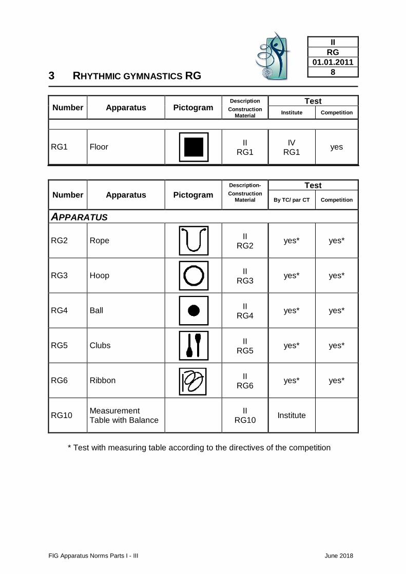
3 RHYTHMIC GYMNASTICS RG
FIG Apparatus Norms Parts I - III June 2018
II
RG
01.01.2011
8
Number Apparatus Pictogram Description Test
Construction Material
Institute Competition
RG1 Floor
II RG1
IV RG1
yes
Number Apparatus Pictogram
Description- Test Construction
Material
By TC/ par CT Competition
APPARATUS
RG2 Rope
II RG2
yes* yes*
RG3 Hoop
II RG3
yes* yes*
RG4 Ball
II RG4
yes* yes*
RG5 Clubs
II RG5
yes* yes*
RG6 Ribbon
II RG6
yes* yes*
RG10 Measurement Table with Balance
II
RG10 Institute
* Test with measuring table according to the directives of the competition
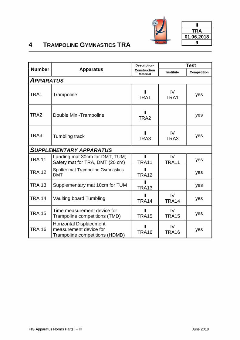
4 TRAMPOLINE GYMNASTICS TRA
FIG Apparatus Norms Parts I - III June 2018
II
TRA
01.06.2018
9
Number Apparatus Description- Test Construction
Material Institute Competition
APPARATUS
TRA1 Trampoline II
TRA1 IV
TRA1 yes
TRA2 Double Mini-Trampoline II
TRA2
yes
TRA3 Tumbling track II
TRA3 IV
TRA3 yes
SUPPLEMENTARY APPARATUS
TRA 11 Landing mat 30cm for DMT, TUM; Safety mat for TRA, DMT (20 cm)
II TRA11
IV TRA11
yes
TRA 12 Spotter mat Trampoline Gymnastics DMT
II TRA12
yes
TRA 13 Supplementary mat 10cm for TUM II
TRA13 yes
TRA 14 Vaulting board Tumbling II
TRA14 IV
TRA14 yes
TRA 15 Time measurement device for Trampoline competitions (TMD)
II TRA15
IV TRA15
yes
TRA 16 Horizontal Displacement measurement device for Trampoline competitions (HDMD)
II TRA16
IV TRA16
yes
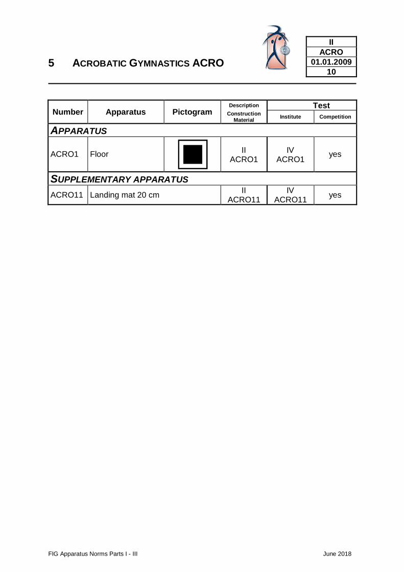
5 ACROBATIC GYMNASTICS ACRO
FIG Apparatus Norms Parts I - III June 2018
II
ACRO
01.01.2009
10
Number Apparatus Pictogram Description Test
Construction Material
Institute Competition
APPARATUS
ACRO1 Floor
II ACRO1
IV ACRO1
yes
SUPPLEMENTARY APPARATUS
ACRO11 Landing mat 20 cm II
ACRO11 IV
ACRO11 yes
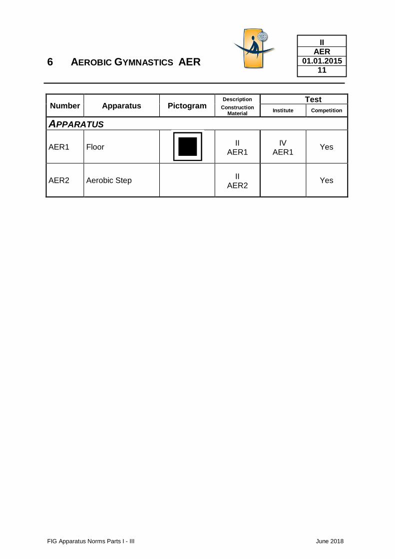
6 AEROBIC GYMNASTICS AER
FIG Apparatus Norms Parts I - III June 2018
II AER
01.01.2015 11
Number Apparatus Pictogram Description Test
Construction Material
Institute Competition
APPARATUS
AER1 Floor
II AER1
IV AER1
Yes
AER2 Aerobic Step
II
AER2
Yes
americanathletic.com
FIG Apparatus Norms Parts I - III June 2018
II
01.01.2009 13
2 Apparatus of the FIG disciplines
Construction and material description, dimensions
2.1 MAG Men’s artistic gymnastics
Floor
FIG Apparatus Norms Parts I - III June 2018
II MAG 1
01.01.2014 14
Use • Men‘s Artistic Gymnastics
Construction / Description of material, measurements
Form
Measurements
Functional Properties
Colours
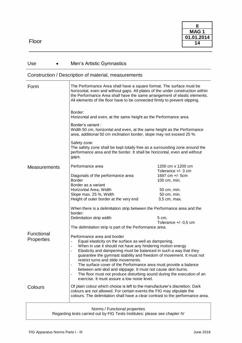
The Performance Area shall have a square format. The surface must be horizontal, even and without gaps. All plates of the under construction within the Performance Area shall have the same arrangement of elastic elements. All elements of the floor have to be connected firmly to prevent slipping.
Border: Horizontal and even, at the same height as the Performance area
Border‘s variant : Width 50 cm, horizontal and even, at the same height as the Performance area, additional 50 cm inclination border, slope may not exceed 25 %.
Safety zone: The safety zone shall be kept totally free as a surrounding zone around the performance area and the border. It shall be horizontal, even and without gaps. Performance area 1200 cm x 1200 cm Tolerance +/- 3 cm Diagonals of the performance area: 1697 cm +/- 5cm Border 100 cm, min. Border as a variant Horizontal Area, Width 50 cm, min. Slope max. 25 %, Width 50 cm, min. Height of outer border at the very end 3,5 cm, max. When there is a delimitation strip between the Performance area and the border: Delimitation strip width 5 cm, Tolerance +/- 0,5 cm The delimitation strip is part of the Performance area. Performance area and border - Equal elasticity on the surface as well as dampening. - When in use it should not have any hindering motion energy - Elasticity and dampening must be balanced in such a way that they
guarantee the gymnast stability and freedom of movement. It must not restrict turns and slide movements.
- The surface cover of the Performance area must provide a balance between anti-skid and slippage. It must not cause skin burns.
- The floor must not produce disturbing sound during the execution of an exercise. It must assure a low noise level.
Of plain colour which choice is left to the manufacturer‘s discretion. Dark colours are not allowed. For certain events the FIG may stipulate the colours. The delimitation shall have a clear contrast to the performance area.
Norms / Functional properties Regarding tests carried out by FIG Tests Institutes: please see chapter IV
Floor
FIG Apparatus Norms Parts I - III June 2018
II MAG 1
01.01.2014 15
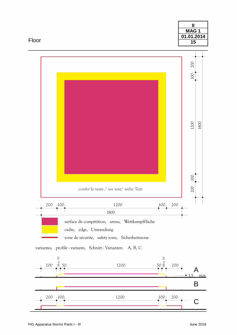
200 100 1200 100 200
200 100 1200 100 200
200 50 1200 50 200
1800
surface de compétition, arena, Wettkampffläche
cadre, edge, Umrandung
zone de sécurité, safety zone, Sicherheitszone
variantes, profile - variants, Schnitt - Varianten A, B, C
200
100
1200
100
200
1800
3,5 max
confer le texte / see text/ siehe Text
Min
50
Min
50
A
B
C
Pommel Horse
FIG Apparatus Norms Parts I - III June 2018
II MAG 2
01.01.2018 16
Use Men's Artistic Gymnastics
Construction / Description of material, measurements
Form
Measurements
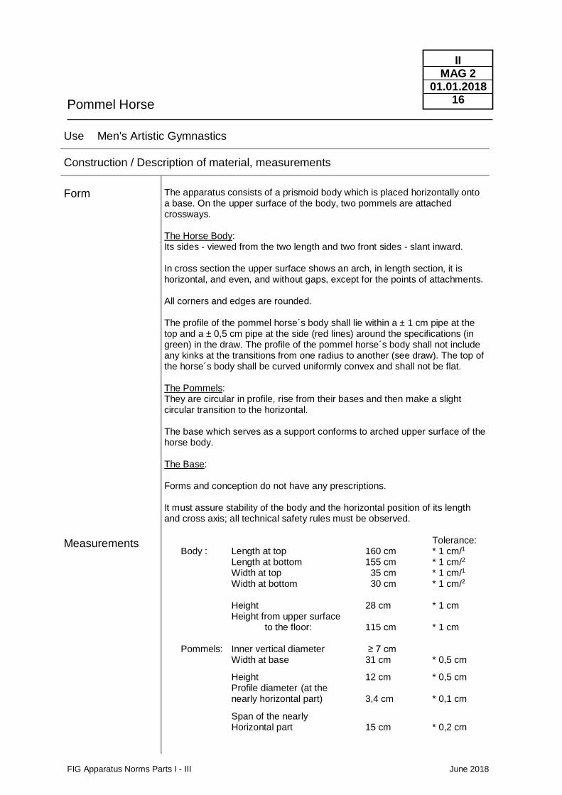
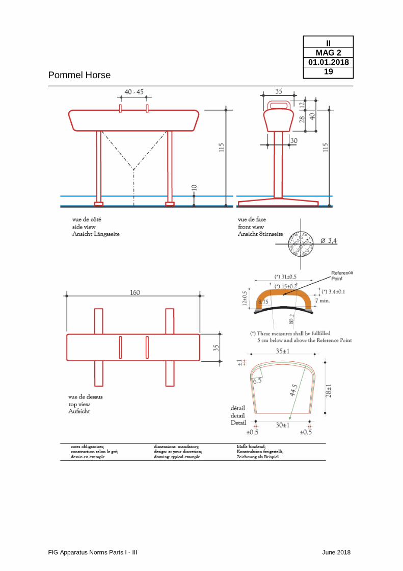
The apparatus consists of a prismoid body which is placed horizontally onto a base. On the upper surface of the body, two pommels are attached crossways. The Horse Body: Its sides - viewed from the two length and two front sides - slant inward. In cross section the upper surface shows an arch, in length section, it is horizontal, and even, and without gaps, except for the points of attachments. All corners and edges are rounded. The profile of the pommel horse´s body shall lie within a ± 1 cm pipe at the top and a ± 0,5 cm pipe at the side (red lines) around the specifications (in green) in the draw. The profile of the pommel horse´s body shall not include any kinks at the transitions from one radius to another (see draw). The top of the horse´s body shall be curved uniformly convex and shall not be flat. The Pommels: They are circular in profile, rise from their bases and then make a slight circular transition to the horizontal. The base which serves as a support conforms to arched upper surface of the horse body. The Base: Forms and conception do not have any prescriptions. It must assure stability of the body and the horizontal position of its length and cross axis; all technical safety rules must be observed. Tolerance: Body : Length at top 160 cm * 1 cm/1 Length at bottom 155 cm * 1 cm/2
Width at top 35 cm * 1 cm/1 Width at bottom 30 cm * 1 cm/2 Height 28 cm * 1 cm Height from upper surface to the floor: 115 cm * 1 cm Pommels: Inner vertical diameter ≥ 7 cm Width at base 31 cm * 0,5 cm
Height 12 cm * 0,5 cm Profile diameter (at the nearly horizontal part) 3,4 cm * 0,1 cm
Span of the nearly Horizontal part 15 cm * 0,2 cm
Pommel Horse
FIG Apparatus Norms Parts I - III June 2018
II MAG 2
01.01.2018 17
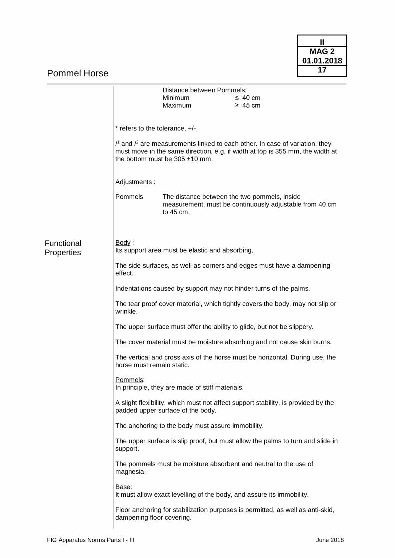
Functional Properties
Distance between Pommels: Minimum ≤ 40 cm Maximum ≥ 45 cm * refers to the tolerance, +/-, /1 and /2 are measurements linked to each other. In case of variation, they must move in the same direction, e.g. if width at top is 355 mm, the width at the bottom must be 305 ±10 mm. Adjustments : Pommels The distance between the two pommels, inside measurement, must be continuously adjustable from 40 cm to 45 cm. Body : Its support area must be elastic and absorbing. The side surfaces, as well as corners and edges must have a dampening effect. Indentations caused by support may not hinder turns of the palms. The tear proof cover material, which tightly covers the body, may not slip or wrinkle. The upper surface must offer the ability to glide, but not be slippery. The cover material must be moisture absorbing and not cause skin burns. The vertical and cross axis of the horse must be horizontal. During use, the horse must remain static. Pommels: In principle, they are made of stiff materials. A slight flexibility, which must not affect support stability, is provided by the padded upper surface of the body. The anchoring to the body must assure immobility. The upper surface is slip proof, but must allow the palms to turn and slide in support. The pommels must be moisture absorbent and neutral to the use of magnesia. Base: It must allow exact levelling of the body, and assure its immobility. Floor anchoring for stabilization purposes is permitted, as well as anti-skid, dampening floor covering.
Pommel Horse
FIG Apparatus Norms Parts I - III June 2018
II MAG 2
01.01.2018 18
Colours
Mats
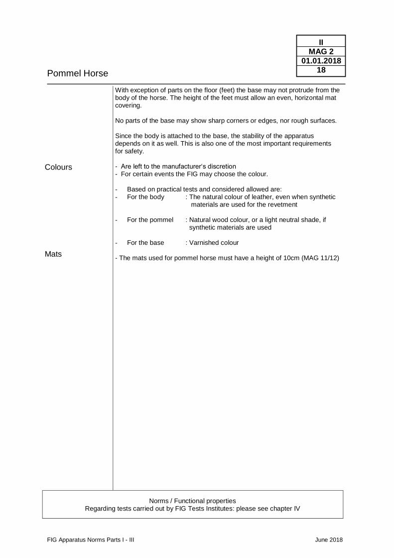
With exception of parts on the floor (feet) the base may not protrude from the body of the horse. The height of the feet must allow an even, horizontal mat covering. No parts of the base may show sharp corners or edges, nor rough surfaces. Since the body is attached to the base, the stability of the apparatus depends on it as well. This is also one of the most important requirements for safety. - Are left to the manufacturer‘s discretion - For certain events the FIG may choose the colour. - Based on practical tests and considered allowed are: - For the body : The natural colour of leather, even when synthetic
materials are used for the revetment
- For the pommel : Natural wood colour, or a light neutral shade, if synthetic materials are used
- For the base : Varnished colour - The mats used for pommel horse must have a height of 10cm (MAG 11/12)
Norms / Functional properties Regarding tests carried out by FIG Tests Institutes: please see chapter IV
Pommel Horse
FIG Apparatus Norms Parts I - III June 2018
II MAG 2
01.01.2018 19
Rings
FIG Apparatus Norms Parts I - III June 2018
II MAG 3
01.01.2015 20
Use • Men‘s Artistic Gymnastics
Construction / Description of material, measurements
Form Measurements
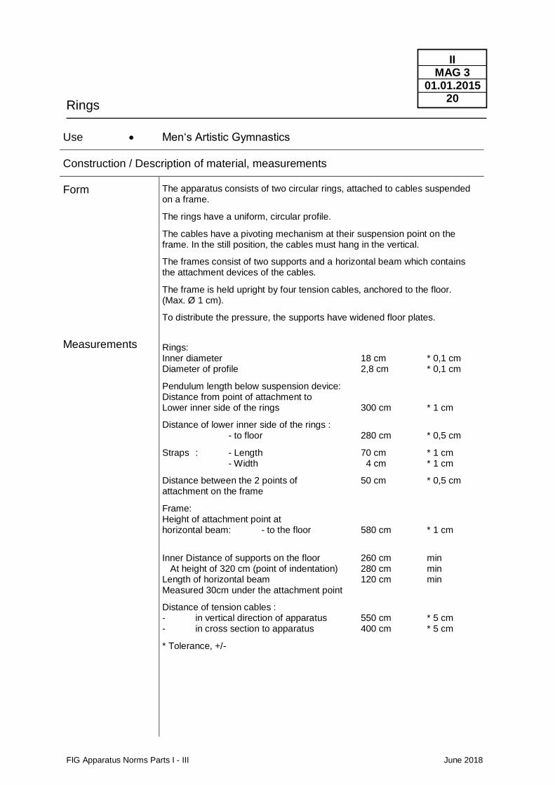
The apparatus consists of two circular rings, attached to cables suspended on a frame.
The rings have a uniform, circular profile.
The cables have a pivoting mechanism at their suspension point on the frame. In the still position, the cables must hang in the vertical.
The frames consist of two supports and a horizontal beam which contains the attachment devices of the cables.
The frame is held upright by four tension cables, anchored to the floor. (Max. Ø 1 cm).
To distribute the pressure, the supports have widened floor plates.
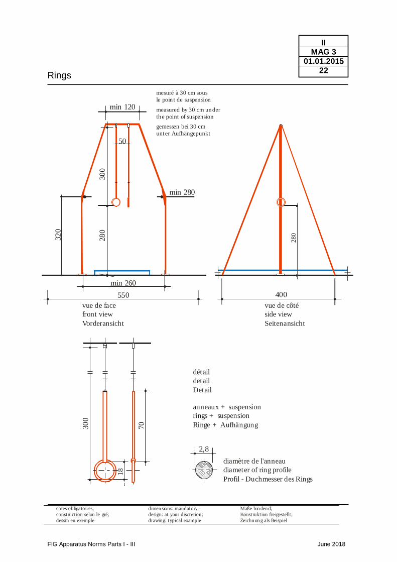
Rings: Inner diameter 18 cm * 0,1 cm Diameter of profile 2,8 cm * 0,1 cm
Pendulum length below suspension device: Distance from point of attachment to Lower inner side of the rings 300 cm * 1 cm
Distance of lower inner side of the rings : - to floor 280 cm * 0,5 cm
Straps : - Length 70 cm * 1 cm - Width 4 cm * 1 cm
Distance between the 2 points of 50 cm * 0,5 cm attachment on the frame
Frame: Height of attachment point at horizontal beam: - to the floor 580 cm * 1 cm
Inner Distance of supports on the floor 260 cm min At height of 320 cm (point of indentation) 280 cm min Length of horizontal beam 120 cm min Measured 30cm under the attachment point
Distance of tension cables : - in vertical direction of apparatus 550 cm * 5 cm - in cross section to apparatus 400 cm * 5 cm
* Tolerance, +/-
Rings
FIG Apparatus Norms Parts I - III June 2018
II MAG 3
01.01.2015 21
Functional Properties
Colour
The suspension device and the rings must be able to swing out freely in all directions. With the exception, of course, of the cable‘s direction. Even submitted to tension, the rings must rotate easily. For this purpose, the pivoting device exists. Under load both rings shall have the same height above the ground. The rings must guarantee a sure grip and therefore must not be slippery. The rings must absorb moisture. The rings as such are made of a stiff material; in effect however, the apparatus must have a certain elasticity, to protect the gymnast‘s joints. This is done partly through form and the method by which the frame is held, and can be helped by an elastic dampening device on the suspension cables. This device however may not produce springy or counter swings. Rings are either made of wood or synthetic material. Except for sanding, the rings' upper surfaces receive no other treatment. The material must remain natural in order to absorb magnesia and moisture so as to assure a sure grip. The pivoting mechanism, the elastic dampening device and the stepless height regulator are connected to the hanging points. The cables are protected by a smooth synthetic cover material. The straps, to which the rings are attached, are made of leather or of a sturdy equivalent material. Aside from the required resistance of materials, the stability of the apparatus must be assured. During the exercise, the frame and the suspension device must not move or cause hindering sways or vibrations. The required elasticity of the suspension device must not produce springy or counter swings. Sharp corners and edges and rough surfaces are to be avoided. The ring cables and fixations must be such that no shortening of the ring cables and straps can occur during the exercises of the gymnasts.
The rings retain the natural colour of the material.
Norms / Functional properties Regarding tests carried out by FIG Tests Institutes : please see chapter IV
Rings
FIG Apparatus Norms Parts I - III June 2018
II MAG 3
01.01.2015 22
Maße bin den d;
Konstruktion freigestellt;
Zeichn un g als Beispiel
vue de face
front view
Vorderansicht
vue de côté
side view
Seitenansicht
550
min 260
28
030
0
50
min 120
gemessen bei 30 cm
unter Aufhängepunkt
measured by 30 cm under
the point of suspension
mesuré à 30 cm sous
le poin t de suspension
min 280
400280
70
30
0
détail
detail
Detail
anneaux + suspension
rings + suspension
Ringe + Aufhängung
diamètre de l'anneau
diameter of ring profile
Profil - Duchmesser des Rings
2,8
18
dimen sions: mandatory;
design: at your discretion;
drawing: typical example
cotes obligatoires;
construction selon le gré;
dessin en exemple
32
0
Vaulting table
FIG Apparatus Norms Parts I - III June 2018
II MAG 4
01.01.2014 23
Use • Men’s Artistic Gymnastics
Construction / Description of material, measurements
Form
Measurements
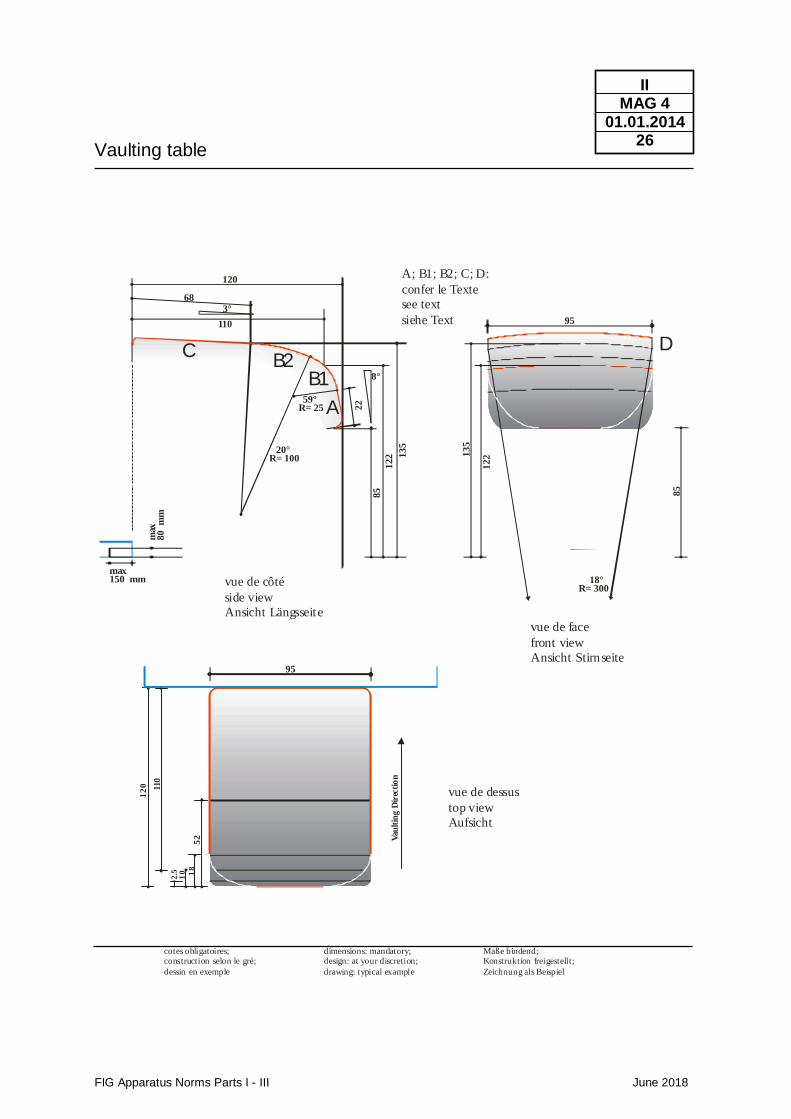
The apparatus consists of a slightly inclined table body which is mounted onto a “monostand” bottom frame. The table body consists of a front surface (A) which, seen from the direction of the vault, is inclined to 8° to the vertical and merges into two arched bends (B1 and B2) and then into a linear cover surface (C) which is inclined 3° to the horizontal. The table body is divided into a bounce area (A) and a push away area (B and C) with a clear colour contrast. The different surfaces merge into each other without any gaps in between. The push away area is slightly rounded in transversal direction (D). All corners and edges are rounded. The bottom frame must offer the table body a stable and secure supporting surface and must guarantee the abidance by the technical safety regulations. The bottom frame with cushioning may not present any parts that protrude from under the vaulting table's body except on the landing side. As a collision protection dangerous metal parts of the support must be cushioned. Recommendation: All levers and locking mechanisms should be incorporated into the under construction. At the landing side the legs of the bottom frame must be cushioned at the same height level as the landing mat (20cm, Tolerance +10cm). The vaulting table including the cushioning of the bottom frame must represent a “monostand” - construction.
Table body: length: 120 cm +/- 1 cm
width: 95 cm +/- 1 cm
Height at the given measurement point (see drawing) )1: 135 cm +/- 1cm
Upper height at the bounce area (see drawing) )1: 122 cm +/- 1 cm
Remark: For competitions the vaulting table must be positioned on a rigid board which has the same height as the run up area (see below) )1 : In competitions the apparatus height must correspond to the top level of the run up area. Maximal orthogonal deviations from the given profile lines in longitudinal
and transversal directions: 1 cm
Protrusion of the leg construction below the table body on the landing side (only allowed with appropriate cut-outs in the landing mat): 15 cm maximal Height of the leg frame 8 cm maximal Circumference of the (cushioned) bottom frame including all levers and fixation devices between the height of 50 cm up to 85 cm 1828mm maximal Distance between the (cushioned) leg construction including all levers and fixation devices and the projection of the table body on all four sides between the height of 50 cm up to 85 cm 25 cm minimal The adjusted height of the vaulting table must be clearly signed at the side.
Vaulting table
FIG Apparatus Norms Parts I - III June 2018
II MAG 4
01.01.2014 24
Functional Properties
Colour
Run up area
Additional Measurements see drawing. The profile lines towards A, B1, B2 and D are to be respected as indicated in the drawing. Maximum deviations
1 cm – measured at a right angle to the profile line. The push away area must be shock-absorbing so that shoulders and wrists are protected. The rebound properties must be guaranteed to be as homogeneously as possible for all the possible impact points on the table body. Extended time-shift for rebounding energy at the impact points caused by extreme deflections is not acceptable. The table body must be evenly cushioned over the entire push away area. The cover material must be non-slippery but not rough. It may not cause a burning sensation on sliding. The bounce area must be cushioned with a high-quality material in order to provide a good collision protection. Recommendation: Any protruding items covered by the cushioning of the stand should be avoided or sufficiently covered to prevent perforation through the cushioning during accidental impact. In order to avoid swaying, vibrations and shifting, the apparatus must have a device for fastening it to the floor.
The colour of the surface material may be chosen according to taste. For certain events the colour may be determined by the FIG.
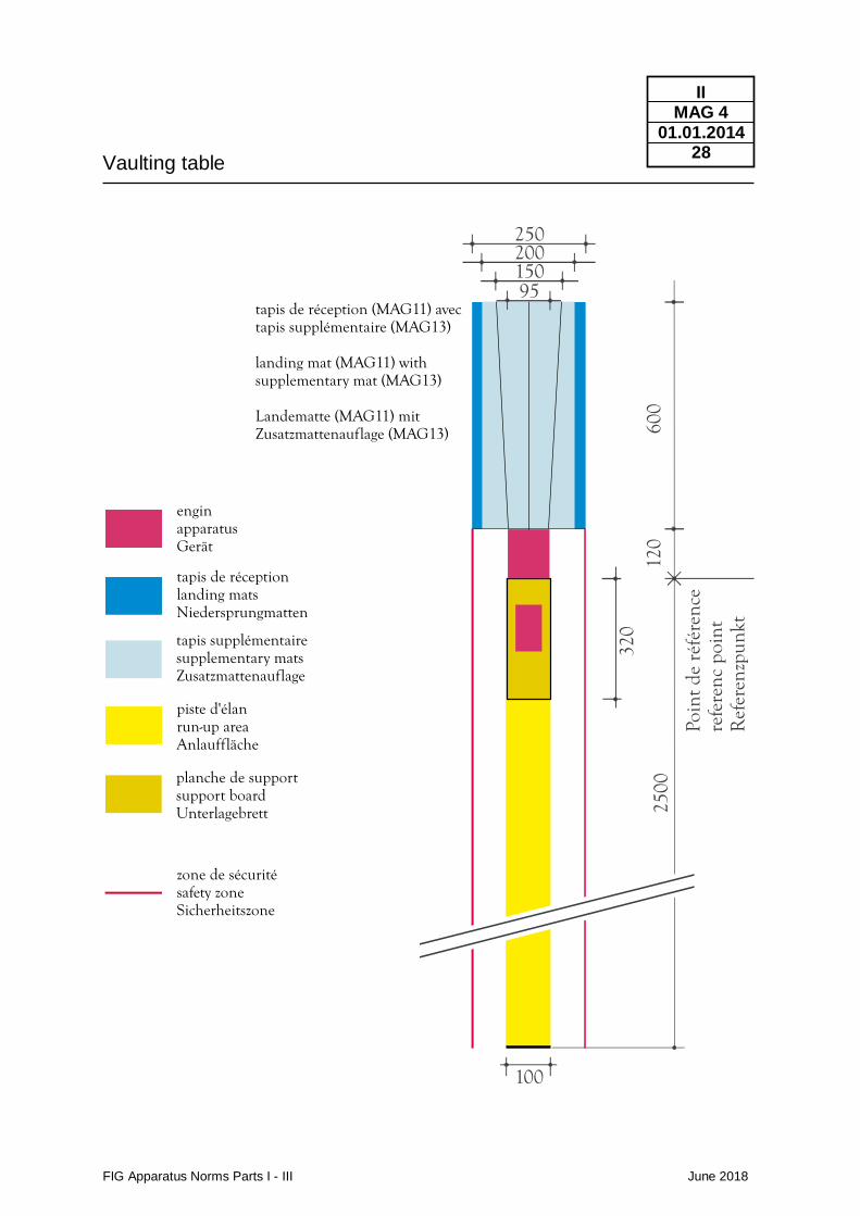
The run-up area is composed of a run-up mat and a rigid board underneath the vaulting board. The run up mat shall be positioned so the carpet threads open in the opposite direction of the gymnast run, offering the greatest friction between the feet and run up mat. The orientation of the run up mat shall be the same in the training halls, warm-up halls, and competition hall. The start of the run-up (2500 cm) shall be marked by a block, attached at the start of the vault run-up mat length (measured from the vertical projection of the beginning of the vaulting table, see “reference point” in the drawing, to the inner side of the block): 2500 + 10 cm width (run-up mat) 100 +/- 1 cm width (rigid board underneath) 100cm min height (same height for run-up mat and board underneath) max 2,5 cm length of the rigid board underneath the vaulting board 320 +/- 1 cm The colour of the run-up area must have a clear contrast to the colour of the vaulting board. The whole run up area (run-up mat and the rigid board underneath) shall have the same colour.
Vaulting table
FIG Apparatus Norms Parts I - III June 2018
II MAG 4
01.01.2014 25
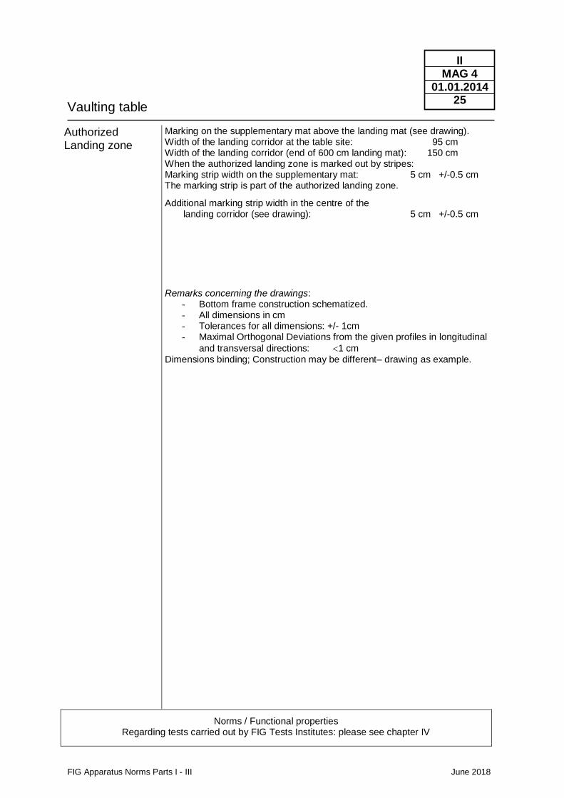
Authorized Landing zone
Marking on the supplementary mat above the landing mat (see drawing). Width of the landing corridor at the table site: 95 cm Width of the landing corridor (end of 600 cm landing mat): 150 cm When the authorized landing zone is marked out by stripes: Marking strip width on the supplementary mat: 5 cm +/-0.5 cm The marking strip is part of the authorized landing zone.
Additional marking strip width in the centre of the landing corridor (see drawing): 5 cm +/-0.5 cm Remarks concerning the drawings:
- Bottom frame construction schematized. - All dimensions in cm - Tolerances for all dimensions: +/- 1cm - Maximal Orthogonal Deviations from the given profiles in longitudinal
and transversal directions: 1 cm
Dimensions binding; Construction may be different– drawing as example.
Norms / Functional properties Regarding tests carried out by FIG Tests Institutes: please see chapter IV
Vaulting table
FIG Apparatus Norms Parts I - III June 2018
II MAG 4
01.01.2014 26
Maße bindend;Konstruktion freigestellt;
Zeichnung als Beispiel
dimensions: mandatory;design: at your discretion;
drawing: typical example
cotes obligatoires;construction selon le gré;
dessin en exemple
85
12
2
95
135
18°R= 300
95
Vau
ltin
g D
irec
tio
n
12
0 110
52
2.5
10 18
85
122 1
35
22
8°
59°R= 25
20°R= 100
3°
120
68
110
max150 mm
max
80
m
m
vue de côté
side view
Ansicht Längsseite
vue de face
front view
Ansicht Stirnseite
A; B1; B2; C; D:
confer le Texte
see text
siehe Text
vue de dessus
top view
Aufsicht
A
B1B2
C D

Vaulting table
FIG Apparatus Norms Parts I - III June 2018
II MAG 4
01.01.2014 27
M aße bin den d;
Kon st rukt ion freigestellt ;
Zeich n u n g als Beispiel
dimen sion s: m an da tory;
design : a t your discret ion ;
drawin g: typical exam ple
cotes obligatoires;
con st ruct ion selon le gré;
dessin en exem ple
Min. 250mm
Max. Length of circum-ference: 1828 mm
Min. 250mm
Min
. 2
50
mm
Min
. 2
50
mm
Vert
ical P
roje
tio
n
Vert
ica
l P
roje
tio
n85
0 m
m
500 m
m
Max. Length of circum-ference: 1828 mm
Vaulting table
FIG Apparatus Norms Parts I - III June 2018
II MAG 4
01.01.2014 28
600
120
320
2500
enginapparatusGerät
tapis de réceptionlanding matsNiedersprungmatten
tapis supplémentairesupplementary matsZusatzmattenauflage
piste d'élanrun-up areaAnlauffläche
planche de supportsupport boardUnterlagebrett
zone de sécuritésafety zoneSicherheitszone
100
25020015095
Poin
tde
réfé
renc
ere
fere
ncpo
int
Ref
eren
zpun
kt
tapis de réception (MAG11) avectapis supplémentaire (MAG13)
landing mat (MAG11) withsupplementary mat (MAG13)
Landematte (MAG11) mitZusatzmattenauflage (MAG13)
Parallel Bars
FIG Apparatus Norms Parts I - III June 2018
II MAG 5
01.01.2017 29
Use • Men‘s Artistic Gymnastics
Construction / Description of material, measurements
Form
Measurements
Functional Properties
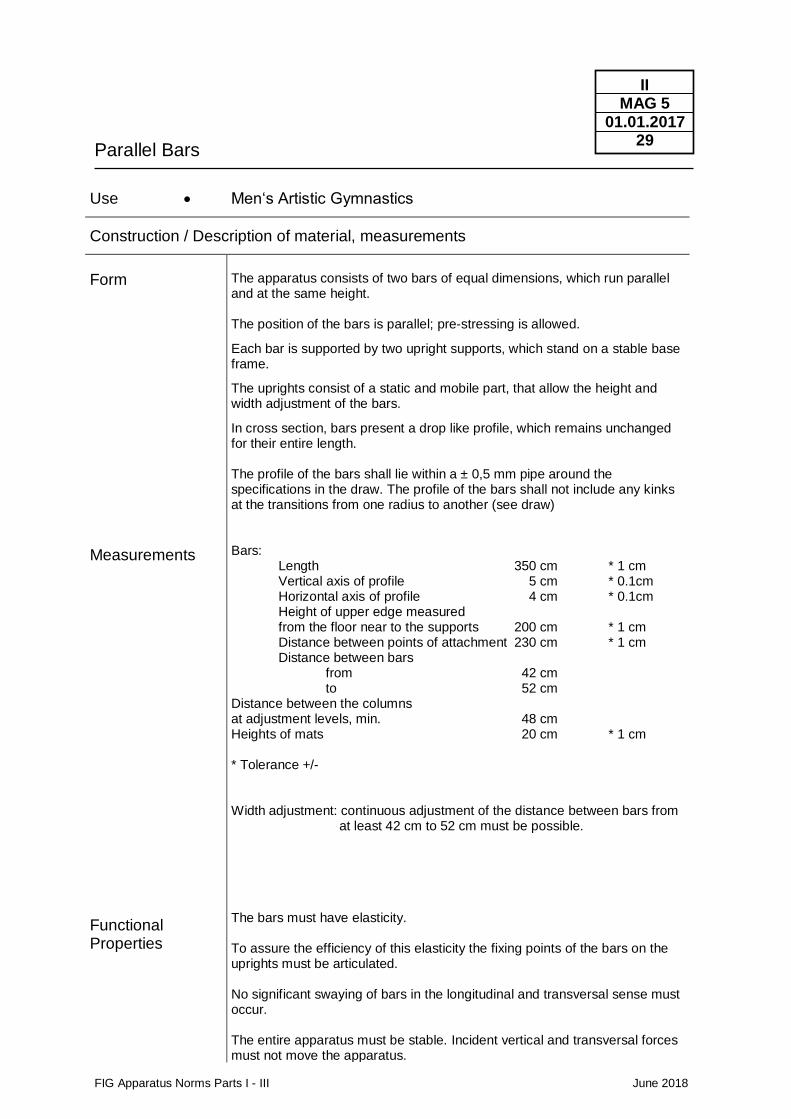
The apparatus consists of two bars of equal dimensions, which run parallel and at the same height. The position of the bars is parallel; pre-stressing is allowed.
Each bar is supported by two upright supports, which stand on a stable base frame.
The uprights consist of a static and mobile part, that allow the height and width adjustment of the bars.
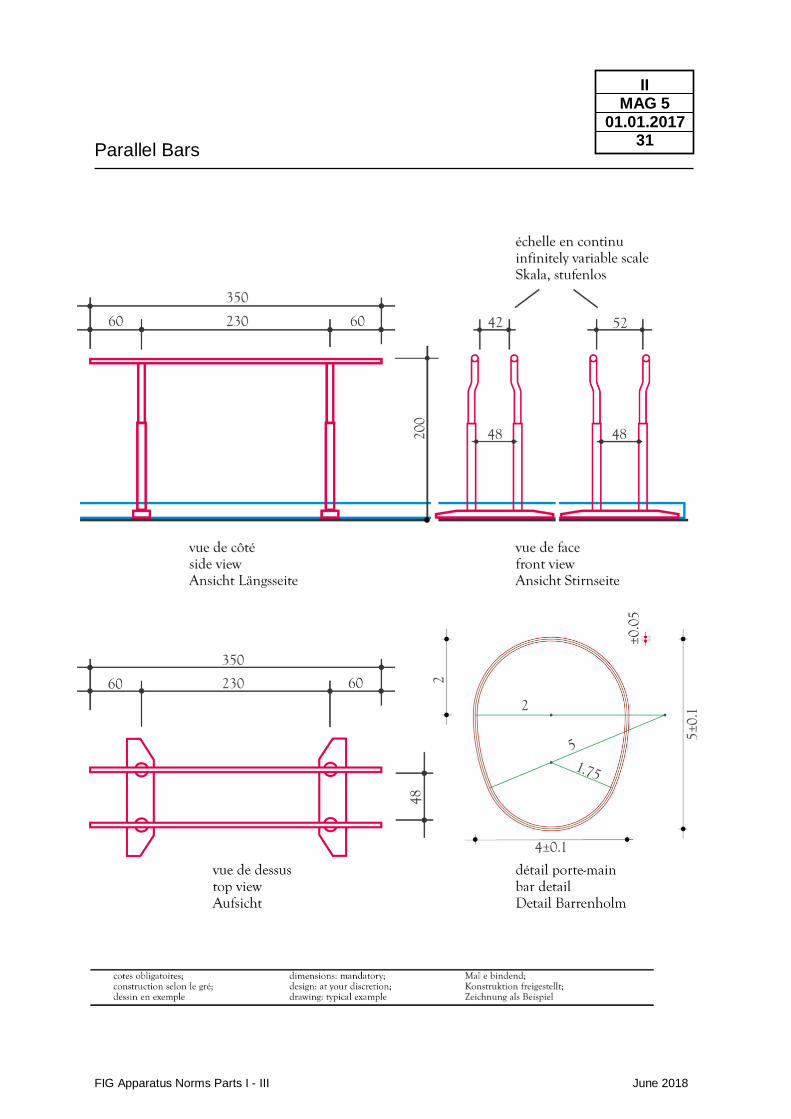
In cross section, bars present a drop like profile, which remains unchanged for their entire length. The profile of the bars shall lie within a ± 0,5 mm pipe around the specifications in the draw. The profile of the bars shall not include any kinks at the transitions from one radius to another (see draw) Bars: Length 350 cm * 1 cm Vertical axis of profile 5 cm * 0.1cm Horizontal axis of profile 4 cm * 0.1cm Height of upper edge measured from the floor near to the supports 200 cm * 1 cm Distance between points of attachment 230 cm * 1 cm Distance between bars from 42 cm to 52 cm Distance between the columns at adjustment levels, min. 48 cm Heights of mats 20 cm * 1 cm * Tolerance +/- Width adjustment: continuous adjustment of the distance between bars from at least 42 cm to 52 cm must be possible. The bars must have elasticity. To assure the efficiency of this elasticity the fixing points of the bars on the uprights must be articulated. No significant swaying of bars in the longitudinal and transversal sense must occur. The entire apparatus must be stable. Incident vertical and transversal forces must not move the apparatus.
Parallel Bars
FIG Apparatus Norms Parts I - III June 2018
II MAG 5
01.01.2017 30
Colours
The upper surface of the bars must be hygroscopic, and not be slippery. The surface of the bars must be made of wood or of other material with similar behaviour. If it is made of wood, it shall be free of errors (knots, fissure, etc.). Except for sanding, it receives no other treatment. The rails must be secured against breaking through. The apparatus must not have sharp corners of edges or any protruding parts. Rough surfaces are to be avoided. The adjustment screws must be warranted against unintended adjustments. The adjustment devices must be double locked to assure that they do not cede during use. The base girders as well as the space between them must be covered by mats. They must be even and without gaps and of the same height as the surrounding mats, forming a uniform surface, from which only the uprights rise. The rails retain the natural wood colour.
Norms / Functional properties Regarding tests carried out by FIG Tests Institutes: please see chapter IV
Parallel Bars
FIG Apparatus Norms Parts I - III June 2018
II MAG 5
01.01.2017 31
Horizontal bar
FIG Apparatus Norms Parts I - III June 2018
II MAG 6
01.01.2014 32
Use • Men‘s Artistic Gymnastics
Construction / Description of material, measurements
Form
Measurements
Functional Properties
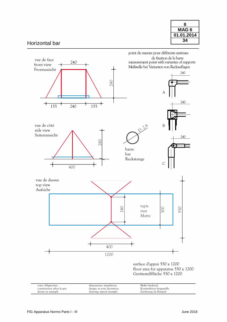
The Horizontal bar consists of a round bar with a constant diameter, which is held horizontally by two supports. The supports stand erect on the floor and have additional floor plates for displacing force. They are held upright by tension cables (Ø max. 1 cm), connected to four floor anchors. Horizontal bar : Diameter 2,8 cm * 0.01 cm Length between attachment points 240 cm * 1 cm Distance between the sockets min 200 cm * 1 cm Height of upper edge : - measured from floor 280 cm * 1 cm The height of the horizontal bar must be adjustable for additional 10 cm to the standard height (280+10 cm * 1 cm). Height changes at competitions to 280+10 cm must be possible by devices at the supports above the upper surface of the landing mat (20 cm). Wires and chains shall be long enough to increment the height. Height increases of 10 cm shall be allowed in competitions for gymnasts who touch the mat with their feet during the exercise. This must be announced to the organizers at the time of the nominative entry and verified by the President or a member of the Superior Jury during the training. Equipment suppliers / Organizers must provide trained staff for a safe, fast and competent height increment if necessary. Distance of floor anchors : - Lengthwise 550 cm * 5 cm - Crosswise 400 cm * 5 cm * Tolerance +/- The horizontal Bar must be elastic, and be secured against breaking through. The elasticity is not just determined by the bar but also by the apparatus, acting as a whole. That is why the placement of the floor anchors, the supports and the tension cables, as well as the degree of tension must be strictly observed to insure uniform elasticity. The bars attachment to the uprights must be articulated, to assure the effectiveness of its elasticity.
Horizontal bar
FIG Apparatus Norms Parts I - III June 2018
II MAG 6
01.01.2014 33
Colours
The bar must allow turn and glide movements without slipping. The apparatus must be stable. The supports must not move or sway during use. Neither the bar nor the tension cables should produce disturbing sounds during use. Preferably such materials should be used which guarantee a slim form and should not block the view. The bar retains the colour of natural polished steel. Colours or designs of the remaining parts are left to the discretion of the manufacturer. The FIG may designate the colour for specific events.
Norms / Functional properties Regarding tests carried out by FIG Tests Institutes: please see chapter IV
Horizontal bar
FIG Apparatus Norms Parts I - III June 2018
II MAG 6
01.01.2014 34
Maße bindend;Konstruktion freigestellt;Zeichnung als Beispiel
550
300
240
vue de facefront viewFrontansicht
vue de dessustop viewAufsicht
surface d'appui 550 x 1200floor area for apparatus 550 x 1200Gerätestellfläche 550 x 1200
barrebarReckstange
400
tapismatMatte
1200
D. 2.8
240
240 15515528
0
dimensions: mandatory;design: at your discretion;drawing: typical example
cotes obligatoires;construction selon le gré;dessin en exemple
vue de côtéside viewSeitenansicht
400
280
240
C
240
B
240
A
point du mesure pour différents systèmes de fixation de la barre
measurement point with variantes of supportsMeßstelle bei Varianten von Reckauflagen
Landing mats
FIG Apparatus Norms Parts I - III June 2018
II MAG 11/12
01.06.2018 35
Use • Men‘s Artistic Gymnastics
Construction / Description of material, measurements
Form
Measurements
Functional Properties
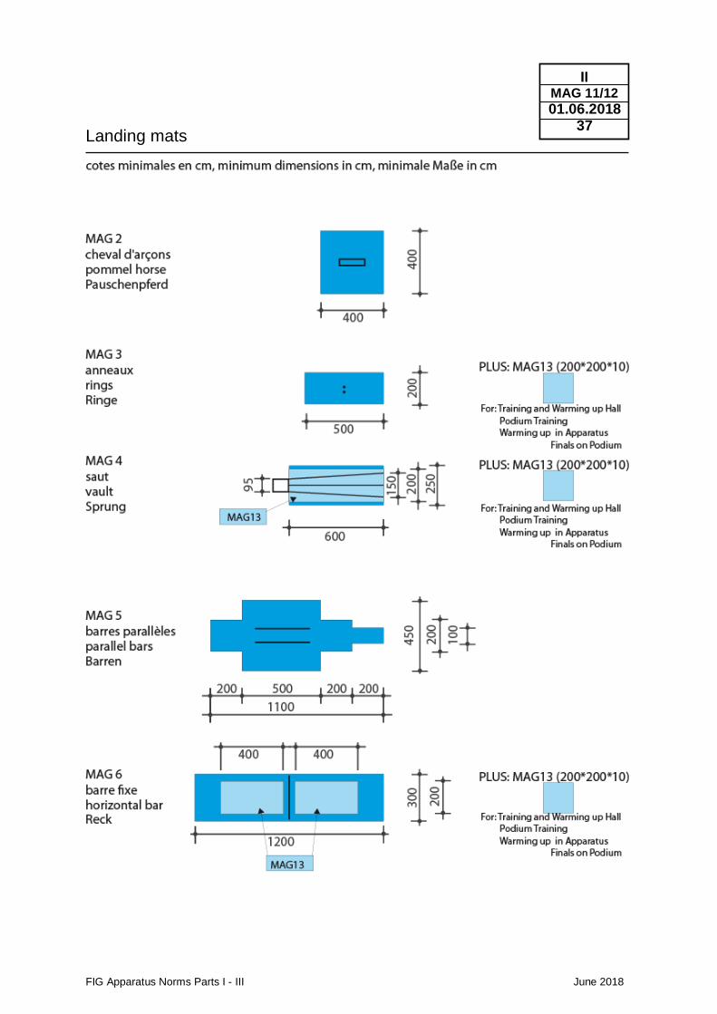
Their upper surface must be horizontal, even and without gaps. Specially designed mats must be used to cover the basis of the apparatus evenly. Height of the landing mats (MAG 3, 4, 5, 6): 20 cm * 1 cm Height of the landing mats pommel horse (MAG 2): 10 cm * 1 cm * Tolerance +/- lengths and widths see drawing Absorbency : Mats must absorb motion energy in order to reduce the reaction transmitted to the body of the landing gymnast to a tolerable proportion. They must respond to increased penetration with an evenly increasing resistance. Stability and Freedom of Movement : Absorbency of the mats must be balanced in order to guarantee standing, walking stability and freedom of movement. Indentations caused by the incidence of compressive forces must not encase the body parts, thereby hindering freedom of movements. They may not be too deep or narrow. If a cover is used, such cover may not plaid and create hindering folds. The mats' upper surface material must offer a balance between anti-slip and slippage. It should be neither slippery nor possess inhibiting resistance. By no means should mats be dislocated during performances. An anti-skid cover on the mats' underside may provide this condition. The border zones of the mats which are pushed together should practically have the same functional properties as the remaining surface. Impacts on the border zones should not cause different indentations than on the remaining surface. For this purpose, and to bridge joints, continuous runners are permitted.
Landing mats
FIG Apparatus Norms Parts I - III June 2018
II MAG 11/12
01.06.2018 36
Colour
Preference should be given to uniform colours. The upper surface must not show optically disturbing patterns or insignia. The FIG may designate the colour for certain events.
Norms / Functional properties Regarding tests carried out by FIG Tests Institutes : please see chapter IV
Landing mats
FIG Apparatus Norms Parts I - III June 2018
II MAG 11/12
01.06.2018 37
Supplementary mats
FIG Apparatus Norms Parts I - III June 2018
II MAG 13
01.01.2016 38
Use • Men‘s Artistic Gymnastics
Construction / Description of material, measurements
Use
Form
Measurements
Functional Properties
The use of a supplementary mat is compulsory in competition for the athletes on the Vault (600 x 200 cm) and on Horizontal Bar (two, 400 x 200 cm). For training (in the training hall and during podium training) and in the warming up hall (correspondingly during the warming up session on the podium before the Apparatus Finals - CIII) an additional supplementary mat (200 x 200 cm) shall be available at the Floor, Rings, Vault and Horizontal Bar. Their upper surface must be horizontal, even and without gaps. The supplementary mats have to be laid on the landing mats (MAG11). At the vault the supplementary mat (600 x 200 cm) shall be attached (i.e. using Velcro). Height of the supplementary mats: 10 cm * 1 cm Vault (MAG4): 600 x 200 cm * 1 cm For the marking of the landing zone see MAG4. Horizontal bar (MAG6, at both sides): 400 x 200 cm * 1 cm Additional supplementary mat for training and warming up: Floor (MAG1), Rings (MAG3), Vault (MAG4), Horizontal bar (MAG6) 200 x 200 cm * 1 cm * Tolerance +/- The foam of the supplementary mats shall have a density of 25 kg / m3 (+/- 2,5 kg /m3). The ultimate tensile strength of the foam (ISO 1798: 2008) shall be ≥ 115 kPa, the compression stress value 40% shall be 4,0 (+/- 1,0) kPa (ISO 3386-1 – Amd1: 2010). By no means should mats be dislocated during performances. At the vault the supplementary mat (600 x 200 cm) shall be attached to the landing mat.
Colour Preference should be given to uniform colours. The upper surface must not show optically disturbing patterns or insignia. The FIG may designate the colour for certain events.
Vaulting board
FIG Apparatus Norms Parts I - III June 2018
II MAG 14
01.01.2016 39
Use • Men’s Artistic Gymnastics - Vault (MAG4) – “hard” and “soft” - Parallel bars (MAG5) – “soft”
Construction / Description of material, measurements
Form
Measurements
Functional Properties
The profile of the vaulting board must adhere exactly to the respective blue print. Its upper surface rises in an arched form, approaching the horizontal between 75 cm and 95 cm, measured from the frontal angle. The height reached at this point, may not be exceeded. After this point, the upper surface may continue horizontally or slope downward. The rise of the arch is 3.5 cm +/- 0,5 cm. For competitions a “soft” and a “hard” vaulting board shall be available. The “hard” board shall be marked with a dot on the surface. - Length 120 cm * 1 cm - Width 60 cm * 1 cm - Height 20 cm * 1 cm - Height (run-up side) max 3 cm - Cushion Cover 2 cm * 0,5 cm - Total height with cushion cover 22 cm * 1,5 cm - Free space between floor and the lower edge of the vaulting board at the run-up side max. 1 cm *Tolerance +/- The stipulated length and height refers to the vertical projection of the upper plate, i.e. the take-off plate. The base may be larger, but cannot extend more than 2 cm beyond the projection of the board. Labelling of the “hard” vaulting bard on the surface by a dot with clear contrast on the longitudinal midline: Distance to the side of run up 5 cm Diameter 8 cm The functional properties of the vaulting board (hardness, damping, elasticity) shall not be adjustable (i.e. springs must be fixed so that they cannot be easily removed by hand). The elasticity of the vaulting board must be most effective in the area between 75 cm and 95 cm, measured horizontally from the frontal angle. The vaulting-board must dampen the counter pressure, i.e. reduce motion energy. Elasticity and absorbency must be evenly distributed, so that the effect of the vaulting board differs only slightly, regardless whether the force of the impact is at the middle axis, or away from it. The upper surface of the vaulting board must offer slip resistance.
Vaulting board
FIG Apparatus Norms Parts I - III June 2018
II MAG 14
01.01.2016 40
Colour
The vaulting board must not produce disturbing sounds during its use. The board shall not slide at the time of impact of the athlete. This shall be achieved by anti-slip devices at the bottom side of the board or at the board underneath the vaulting board. The slip resistance shall be provided especially when the board bottoms out at the middle part. The vaulting board and its base may not have any sharp corners, edges and no protruding parts. Mainly the upper and under edge of the upper part of the Vaulting board towards the apparatus side (Vaulting Table, Balance Beam of Uneven Bars) shall be cushioned and rounded. The choice of colour is left to the discretion of the manufacturer. With exception of the dot for “hard” vaulting boards optically disturbing patterns, stripes or insignia on the upper surface are not permitted. The FIG may designate the colour for certain events.
Norms / Functional properties Regarding tests carried out by FIG Tests Institutes : please see chapter IV

Vaulting board
FIG Apparatus Norms Parts I - III June 2018
II MAG 14
01.01.2016 41
Vaulting Board safety collar (Round off vaults)
FIG Apparatus Norms Parts I - III June 2018
II MAG 15
01.01.2018 42
Use • Men‘s Artistic Gymnastics
Construction / Description of material, measurements
Use
Form
Measurements
Functional Properties
The usage of the safety collar around the vaulting board is compulsory for round-off entries at the vault. It is not allowed to place the safety collar on the foot of the vaulting table or underneath the vaulting table. The safety collar is “u-shaped” and surrounds the vaulting board at the sides and the front toward the vaulting table. At the sides of the vaulting board its upper surface rises in an arched form in the same level as the vaulting board. At the front side of the vaulting board the surface of the safety collar is horizontal and even. The whole surface of the safety collar and the corresponding surface of the vaulting board need to be of the same height level. Overall length: 120 cm (±20 cm) Minimal width at the side of the vaulting board: 20 cm Length at the front part of the vaulting board: 20 cm (± 0,5 cm) Maximal Difference between the height of the safety collars’ and the boards’ surface (respecting the arched form): ±1 cm Maximal gap between the safety collar and the vaulting board on all three sides: 0,5 cm The safety collar has to provide a safe area around the vaulting board in case of an athlete misses the board for a take-off towards the vaulting table, therefore the safety collar must provide sufficient stability and cushioning at the whole upper surface. The bottom side shall have an “anti-slip” surface (i.e. Velcro) to prevent the safety collar from slipping away. The safety collar shall not hinder the vaulting board in its functional properties neither by restricting the airflow during the compression of the vaulting board nor hindering the movement of the upper parts during foot contact.
Colour The upper surface must not show optically disturbing patterns or insignia. The colour must be uniform and in contrast to the vaulting board. The FIG may designate the colour for certain events.
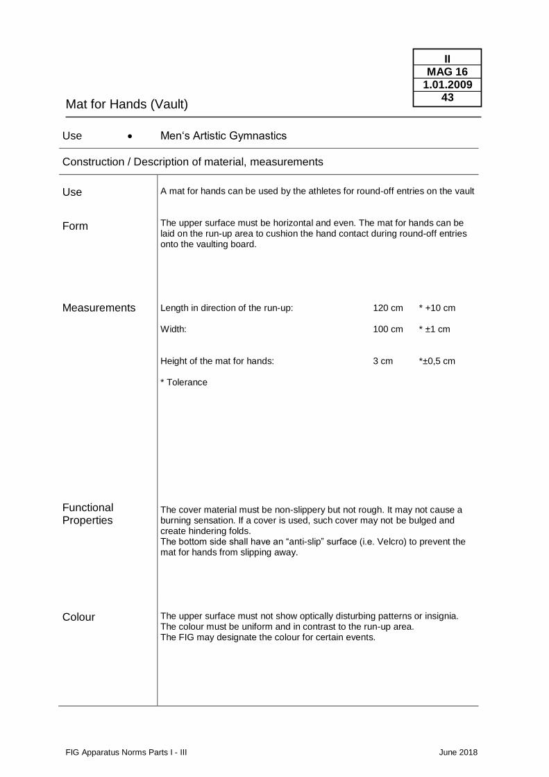
Mat for Hands (Vault)
FIG Apparatus Norms Parts I - III June 2018
II MAG 16
1.01.2009 43
Use • Men‘s Artistic Gymnastics
Construction / Description of material, measurements
Use
Form
Measurements
Functional Properties
A mat for hands can be used by the athletes for round-off entries on the vault The upper surface must be horizontal and even. The mat for hands can be laid on the run-up area to cushion the hand contact during round-off entries onto the vaulting board. Length in direction of the run-up: 120 cm * +10 cm Width: 100 cm * ±1 cm Height of the mat for hands: 3 cm *±0,5 cm * Tolerance The cover material must be non-slippery but not rough. It may not cause a burning sensation. If a cover is used, such cover may not be bulged and create hindering folds. The bottom side shall have an “anti-slip” surface (i.e. Velcro) to prevent the mat for hands from slipping away.
Colour The upper surface must not show optically disturbing patterns or insignia. The colour must be uniform and in contrast to the run-up area. The FIG may designate the colour for certain events.
FIG Apparatus Norms Parts I - III June 2018
II WAG
01.01.2014 44
2.2 WAG Women’s artistic gymnastics
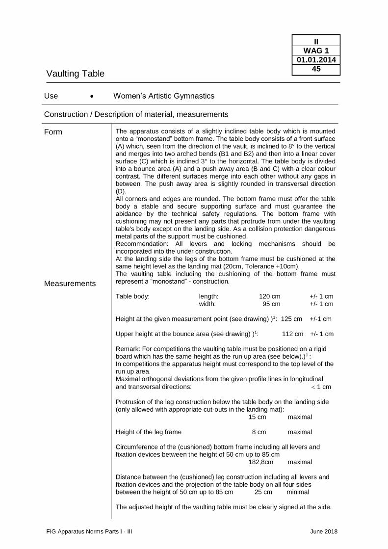
Vaulting Table
FIG Apparatus Norms Parts I - III June 2018
II WAG 1
01.01.2014 45
Use • Women’s Artistic Gymnastics
Construction / Description of material, measurements
Form
Measurements
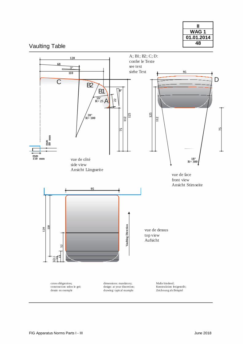
The apparatus consists of a slightly inclined table body which is mounted onto a “monostand” bottom frame. The table body consists of a front surface (A) which, seen from the direction of the vault, is inclined to 8° to the vertical and merges into two arched bends (B1 and B2) and then into a linear cover surface (C) which is inclined 3° to the horizontal. The table body is divided into a bounce area (A) and a push away area (B and C) with a clear colour contrast. The different surfaces merge into each other without any gaps in between. The push away area is slightly rounded in transversal direction (D). All corners and edges are rounded. The bottom frame must offer the table body a stable and secure supporting surface and must guarantee the abidance by the technical safety regulations. The bottom frame with cushioning may not present any parts that protrude from under the vaulting table's body except on the landing side. As a collision protection dangerous metal parts of the support must be cushioned. Recommendation: All levers and locking mechanisms should be incorporated into the under construction. At the landing side the legs of the bottom frame must be cushioned at the same height level as the landing mat (20cm, Tolerance +10cm). The vaulting table including the cushioning of the bottom frame must represent a “monostand” - construction.
Table body: length: 120 cm +/- 1 cm
width: 95 cm +/- 1 cm
Height at the given measurement point (see drawing) )1: 125 cm +/-1 cm
Upper height at the bounce area (see drawing) )1: 112 cm +/- 1 cm
Remark: For competitions the vaulting table must be positioned on a rigid board which has the same height as the run up area (see below).)1 : In competitions the apparatus height must correspond to the top level of the run up area. Maximal orthogonal deviations from the given profile lines in longitudinal
and transversal directions: 1 cm
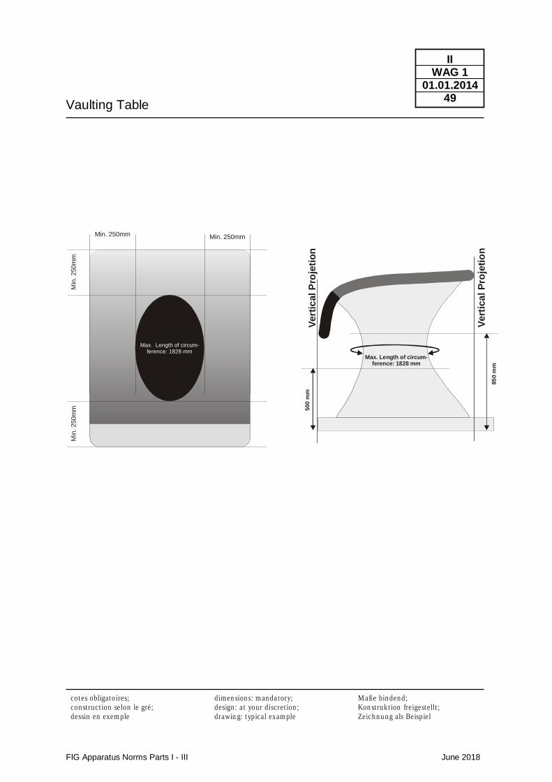
Protrusion of the leg construction below the table body on the landing side (only allowed with appropriate cut-outs in the landing mat): 15 cm maximal Height of the leg frame 8 cm maximal Circumference of the (cushioned) bottom frame including all levers and fixation devices between the height of 50 cm up to 85 cm 182,8cm maximal Distance between the (cushioned) leg construction including all levers and fixation devices and the projection of the table body on all four sides between the height of 50 cm up to 85 cm 25 cm minimal The adjusted height of the vaulting table must be clearly signed at the side.
Vaulting Table
FIG Apparatus Norms Parts I - III June 2018
II WAG 1
01.01.2014 46
Functional Properties
Colour
Run up area Authorized
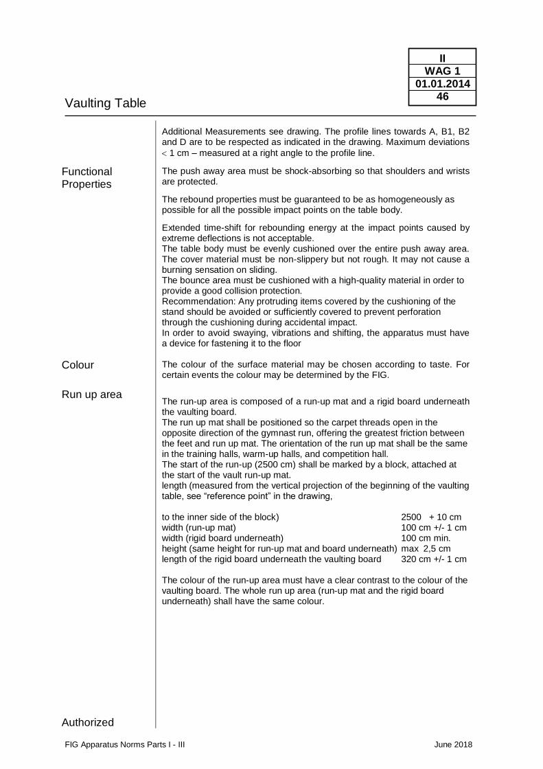
Additional Measurements see drawing. The profile lines towards A, B1, B2 and D are to be respected as indicated in the drawing. Maximum deviations
1 cm – measured at a right angle to the profile line.
The push away area must be shock-absorbing so that shoulders and wrists are protected.
The rebound properties must be guaranteed to be as homogeneously as possible for all the possible impact points on the table body.
Extended time-shift for rebounding energy at the impact points caused by extreme deflections is not acceptable. The table body must be evenly cushioned over the entire push away area. The cover material must be non-slippery but not rough. It may not cause a burning sensation on sliding. The bounce area must be cushioned with a high-quality material in order to provide a good collision protection. Recommendation: Any protruding items covered by the cushioning of the stand should be avoided or sufficiently covered to prevent perforation through the cushioning during accidental impact. In order to avoid swaying, vibrations and shifting, the apparatus must have a device for fastening it to the floor The colour of the surface material may be chosen according to taste. For certain events the colour may be determined by the FIG.
The run-up area is composed of a run-up mat and a rigid board underneath the vaulting board. The run up mat shall be positioned so the carpet threads open in the opposite direction of the gymnast run, offering the greatest friction between the feet and run up mat. The orientation of the run up mat shall be the same in the training halls, warm-up halls, and competition hall. The start of the run-up (2500 cm) shall be marked by a block, attached at the start of the vault run-up mat. length (measured from the vertical projection of the beginning of the vaulting table, see “reference point” in the drawing, to the inner side of the block) 2500 + 10 cm width (run-up mat) 100 cm +/- 1 cm width (rigid board underneath) 100 cm min. height (same height for run-up mat and board underneath) max 2,5 cm length of the rigid board underneath the vaulting board 320 cm +/- 1 cm The colour of the run-up area must have a clear contrast to the colour of the vaulting board. The whole run up area (run-up mat and the rigid board underneath) shall have the same colour.
Vaulting Table
FIG Apparatus Norms Parts I - III June 2018
II WAG 1
01.01.2014 47
Landing zone
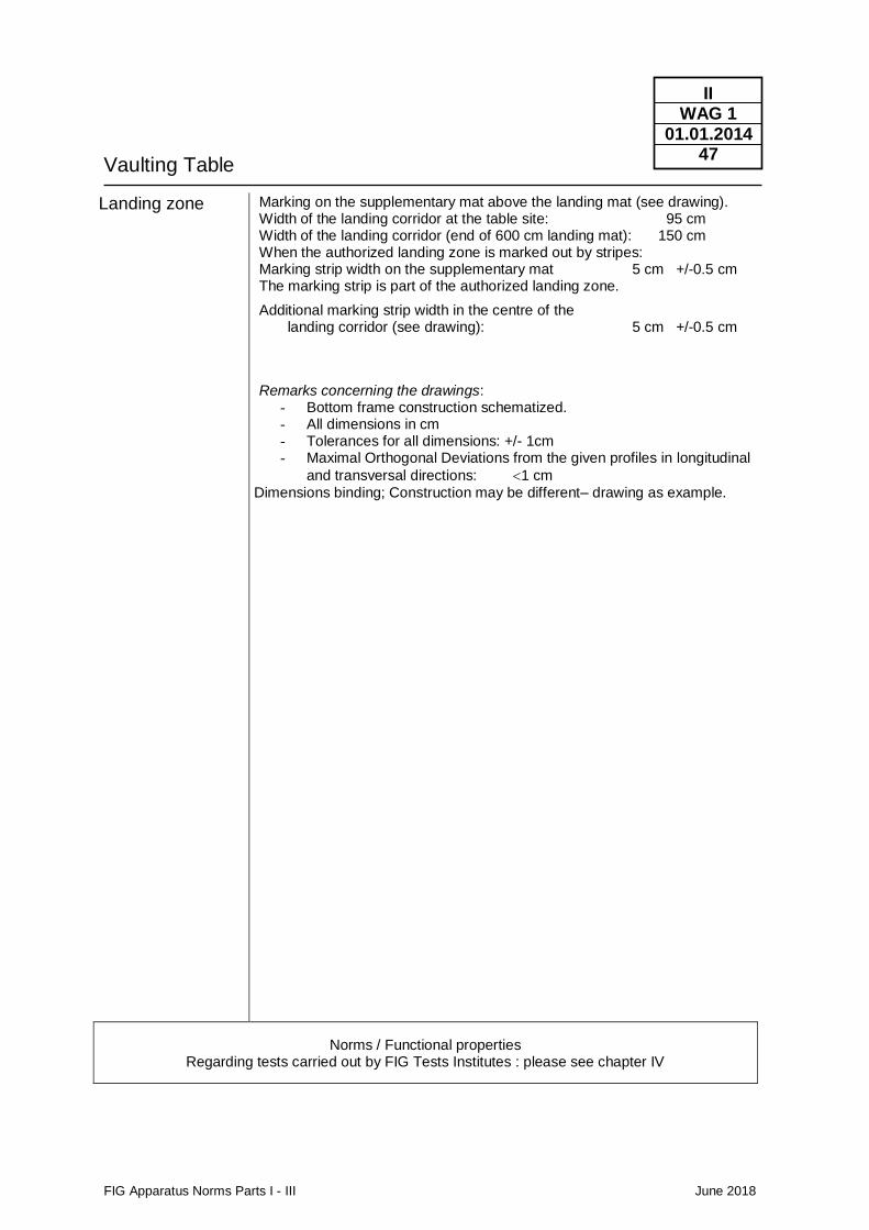
Marking on the supplementary mat above the landing mat (see drawing). Width of the landing corridor at the table site: 95 cm Width of the landing corridor (end of 600 cm landing mat): 150 cm When the authorized landing zone is marked out by stripes: Marking strip width on the supplementary mat 5 cm +/-0.5 cm The marking strip is part of the authorized landing zone.
Additional marking strip width in the centre of the landing corridor (see drawing): 5 cm +/-0.5 cm
Remarks concerning the drawings: - Bottom frame construction schematized. - All dimensions in cm - Tolerances for all dimensions: +/- 1cm - Maximal Orthogonal Deviations from the given profiles in longitudinal
and transversal directions: 1 cm
Dimensions binding; Construction may be different– drawing as example.
Norms / Functional properties Regarding tests carried out by FIG Tests Institutes : please see chapter IV
Vaulting Table
FIG Apparatus Norms Parts I - III June 2018
II WAG 1
01.01.2014 48
Maße bindend;Konstruktion freigestellt;
Zeichnung als Beispiel
dimensions: mandatory;design: at your discretion;
drawing: typical example
cotes obligatoires;construction selon le gré;
dessin en exemple
75
11
2
95
12
5
18°R= 300
95
Vau
ltin
g D
irec
tio
n
12
0 110
52
2.5
10 18
75
112 1
25
22
8°
59°R= 25
20°R= 100
3°
120
68
110
max150 mm
max
80
m
m
vue de côté
side view
Ansicht Längsseite
vue de face
front view
Ansicht Stirnseite
vue de dessus
top view
Aufsicht
A; B1; B2; C; D:
confer le Texte
see text
siehe Text
A
B1B2
C D
Vaulting Table
FIG Apparatus Norms Parts I - III June 2018
II WAG 1
01.01.2014 49
M aße bin den d;
Kon st rukt ion freigestellt ;
Zeich n u n g als Beispiel
dimen sion s: m an da tory;
design : a t your discret ion ;
drawin g: typical exam ple
cotes obligatoires;
con st ruct ion selon le gré;
dessin en exem ple
Min. 250mm
Max. Length of circum-ference: 1828 mm
Min. 250mm
Min
. 2
50
mm
Min
. 2
50
mm
Vert
ical P
roje
tio
n
Vert
ica
l P
roje
tio
n85
0 m
m
500 m
m
Max. Length of circum-ference: 1828 mm
Vaulting Table
FIG Apparatus Norms Parts I - III June 2018
II WAG 1
01.01.2014 50
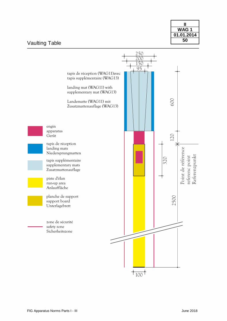
600
120
320
2500
enginapparatusGerät
tapis de réceptionlanding matsNiedersprungmatten
tapis supplémentairesupplementary matsZusatzmattenauflage
piste d'élanrun-up areaAnlauffläche
planche de supportsupport boardUnterlagebrett
zone de sécuritésafety zoneSicherheitszone
100
25020015095
Poin
tde
réfé
renc
ere
fere
ncpo
int
Ref
eren
zpun
kt
tapis de réception (WAG11)avectapis supplémentaire (WAG13)
landing mat (WAG11) withsupplementary mat (WAG13)
Landematte (WAG11) mitZusatzmattenauflage (WAG13)
Uneven Bars
FIG Apparatus Norms Parts I - III June 2018
II WAG 2
01.01.2018 51
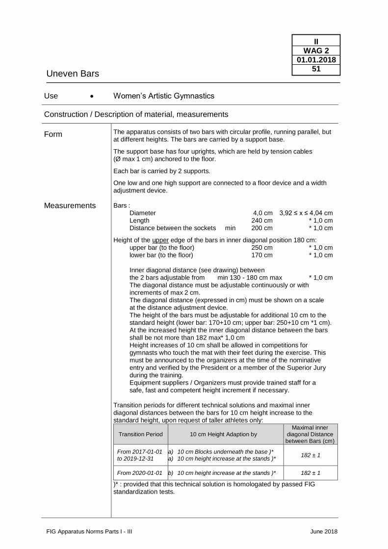
Use • Women’s Artistic Gymnastics
Construction / Description of material, measurements
Form
Measurements
The apparatus consists of two bars with circular profile, running parallel, but at different heights. The bars are carried by a support base.
The support base has four uprights, which are held by tension cables (Ø max 1 cm) anchored to the floor.
Each bar is carried by 2 supports.
One low and one high support are connected to a floor device and a width adjustment device. Bars : Diameter 4,0 cm 3,92 ≤ x ≤ 4,04 cm Length 240 cm * 1,0 cm Distance between the sockets min 200 cm * 1,0 cm
Height of the upper edge of the bars in inner diagonal position 180 cm: upper bar (to the floor) 250 cm * 1,0 cm lower bar (to the floor) 170 cm * 1,0 cm Inner diagonal distance (see drawing) between the 2 bars adjustable from min 130 - 180 cm max * 1,0 cm The diagonal distance must be adjustable continuously or with increments of max 2 cm. The diagonal distance (expressed in cm) must be shown on a scale at the distance adjustment device. The height of the bars must be adjustable for additional 10 cm to the standard height (lower bar: 170+10 cm; upper bar: 250+10 cm *1 cm). At the increased height the inner diagonal distance between the bars shall be not more than 182 max* 1,0 cm Height increases of 10 cm shall be allowed in competitions for gymnasts who touch the mat with their feet during the exercise. This must be announced to the organizers at the time of the nominative entry and verified by the President or a member of the Superior Jury during the training. Equipment suppliers / Organizers must provide trained staff for a safe, fast and competent height increment if necessary. Transition periods for different technical solutions and maximal inner diagonal distances between the bars for 10 cm height increase to the standard height, upon request of taller athletes only:
Transition Period 10 cm Height Adaption by Maximal inner
diagonal Distance between Bars (cm)
From 2017-01-01 to 2019-12-31
a) 10 cm Blocks underneath the base )* a) 10 cm height increase at the stands )*
182 ± 1
From 2020-01-01 b) 10 cm height increase at the stands )* 182 ± 1
)* : provided that this technical solution is homologated by passed FIG standardization tests.
Uneven Bars
FIG Apparatus Norms Parts I - III June 2018
II WAG 2
01.01.2018 52
Functional Properties
Colour
Distance of floor anchors : lengthwise 550 cm * 5 cm crosswise 400 cm * 5 cm
Both bars must have the same, uniform elasticity. To assure this, their supports must be articulated.
The bar surface must provide a good glide and turn capability but may not be slippery.
To ensure grip stability, the bars' surface must absorb moisture.
The bars must be secured (reinforced) against breaking through.
A safeguard system must prevent an unintended release of the movable components of the apparatus.
When the apparatus is used for performances, no hindering sways or vibrations and counter swings should occur.
The bars retain the natural colour of wood. They are neither lacquered, nor polished.
Norms / Functional properties Regarding tests carried out by FIG Tests Institutes : please see chapter IV
Uneven Bars
FIG Apparatus Norms Parts I - III June 2018
II WAG 2
01.01.2018 53
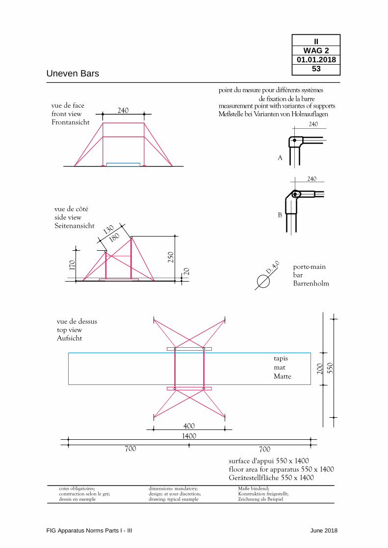
vue de facefront viewFrontansicht
vue de côtéside viewSeitenansicht
240
250
20
170
130
180
4001400
700 700
porte-mainbarBarrenholm
D. 4,0
surface d'appui 550 x 1400floor area for apparatus 550 x 1400Gerätestellfläche 550 x 1400
200
550
tapismatMatte
vue de dessustop viewAufsicht
Maße bindend;Konstruktion freigestellt;Zeichnung als Beispiel
cotes obligatoires;construction selon le gré;dessin en exemple
dimensions: mandatory;design: at your discretion;drawing: typical example
240
B
240
A
point du mesure pour différents systèmes de fixation de la barre
measurement point with variantes of supportsMeßstelle bei Varianten von Holmauflagen
Balance Beam
FIG Apparatus Norms Parts I - III June 2018
II WAG 3
01.01.2011 54
Use • Women’s Artistic Gymnastics
Construction / Description of material, measurements
Form
Measurements
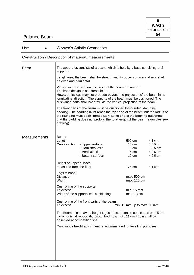
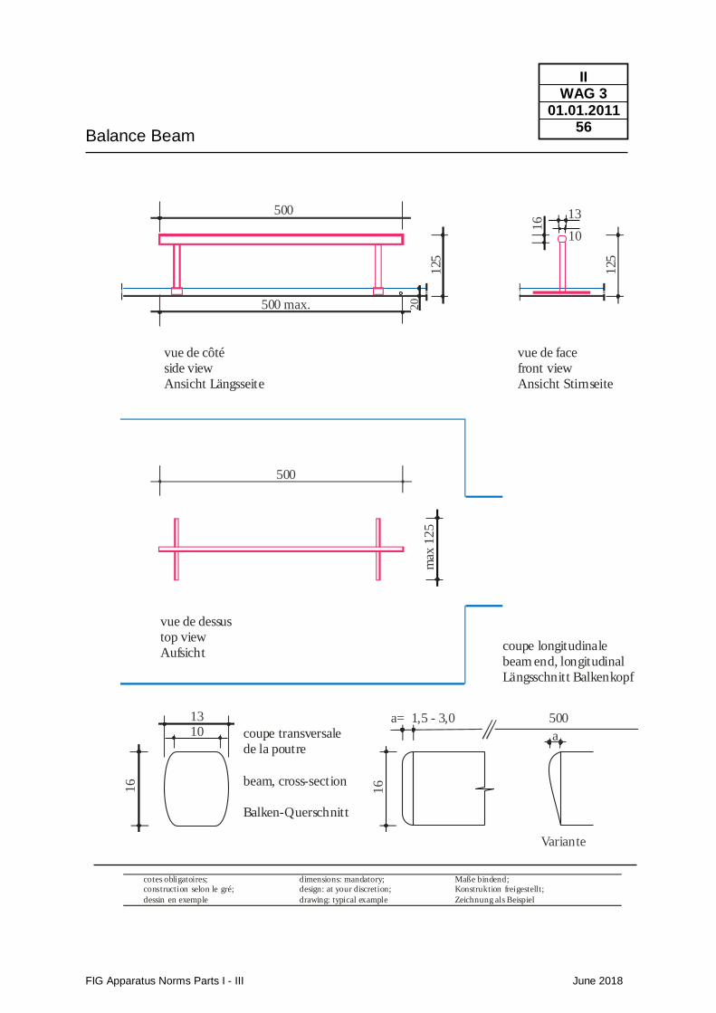
The apparatus consists of a beam, which is held by a base consisting of 2 supports.
Lengthwise, the beam shall be straight and its upper surface and axis shall be even and horizontal.
Viewed in cross section, the sides of the beam are arched. The base design is not prescribed. However, its legs may not protrude beyond the projection of the beam in its longitudinal direction. The supports of the beam must be cushioned. The cushioned parts shall not protrude the vertical projection of the beam.
The front parts of the beam must be cushioned by rounded, damping padding. The padding must reach the top edge of the beam, but the radius of the rounding must begin immediately at the end of the beam to guarantee that the padding does not prolong the total length of the beam (examples see drawing)
Beam: Length 500 cm * 1 cm Cross section: - Upper surface 10 cm * 0,5 cm - Horizontal axis 13 cm * 0,5 cm - Vertical axis 16 cm * 0,5 cm - Bottom surface 10 cm * 0,5 cm Height of upper surface measured from the floor 125 cm * 1 cm
Legs of base: Distance max. 500 cm Width max. 125 cm
Cushioning of the supports: Thickness min. 15 mm Width of the supports incl. cushioning max. 13 cm Cushioning of the front parts of the beam: Thickness min. 15 mm up to max. 30 mm The Beam might have a height adjustment. It can be continuous or in 5 cm increments. However, the prescribed height of 125 cm * 1cm shall be observed at competition site.
Continuous height adjustment is recommended for levelling purposes.
Balance Beam
FIG Apparatus Norms Parts I - III June 2018
II WAG 3
01.01.2011 55
Functional Properties
Colour
The surface must have impact absorbent characteristics to protect the gymnast‘s joints and limbs. It should also have elasticity to support the jumps.
One of the most important properties of the beam is that it must be step safe. Elasticity must be equally distributed and must not disturb a sure step.
The upper surface material of the beam must permit effortless gliding and turning, but not be slippery.
The front parts of the beam must be padded.
The cover material must not produce skin burns. The upper edge of the padding at the front parts of the beam shall not be harder than the surface of the beam. All protruding parts, especially screws underneath the balance beam shall be cushioned or hidden. During an exercise, the beam may not move, topple or sway.
The colour of the beam must distinctly differ from the colour of the mats.
Norms / Functional properties Regarding tests carried out by FIG Tests Institutes : please see chapter IV
Balance Beam
FIG Apparatus Norms Parts I - III June 2018
II WAG 3
01.01.2011 56
Maße bindend;Konstruktion freigestellt;
Zeichnung als Beispiel
vue de dessus
top view
Aufsicht
500
125
max
12
52
0500 max.
13
10
16
500
vue de côté
side view
Ansicht Längsseite
vue de face
front view
Ansicht Stirnseite
dimensions: mandatory;design: at your discretion;
drawing: typical example
cotes obligatoires;construction selon le gré;
dessin en exemple
125
13
16
16
50010 coupe transversale
de la poutre
beam, cross-section
Balken-Querschnitt
a= 1,5 - 3,0
a
Variante
coupe longitudinale
beam end, longitudinal
Längsschnitt Balkenkopf
Floor
FIG Apparatus Norms Parts I - III June 2018
II WAG 4
01.01.2014 57
Use • Women’s Artistic Gymnastics
Construction / Description of material, measurements
Form
Measurements
Functional Properties
Colour
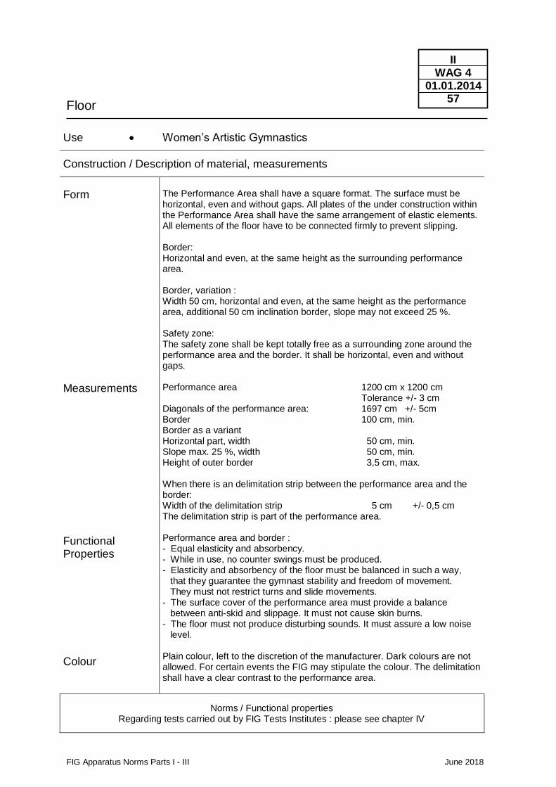
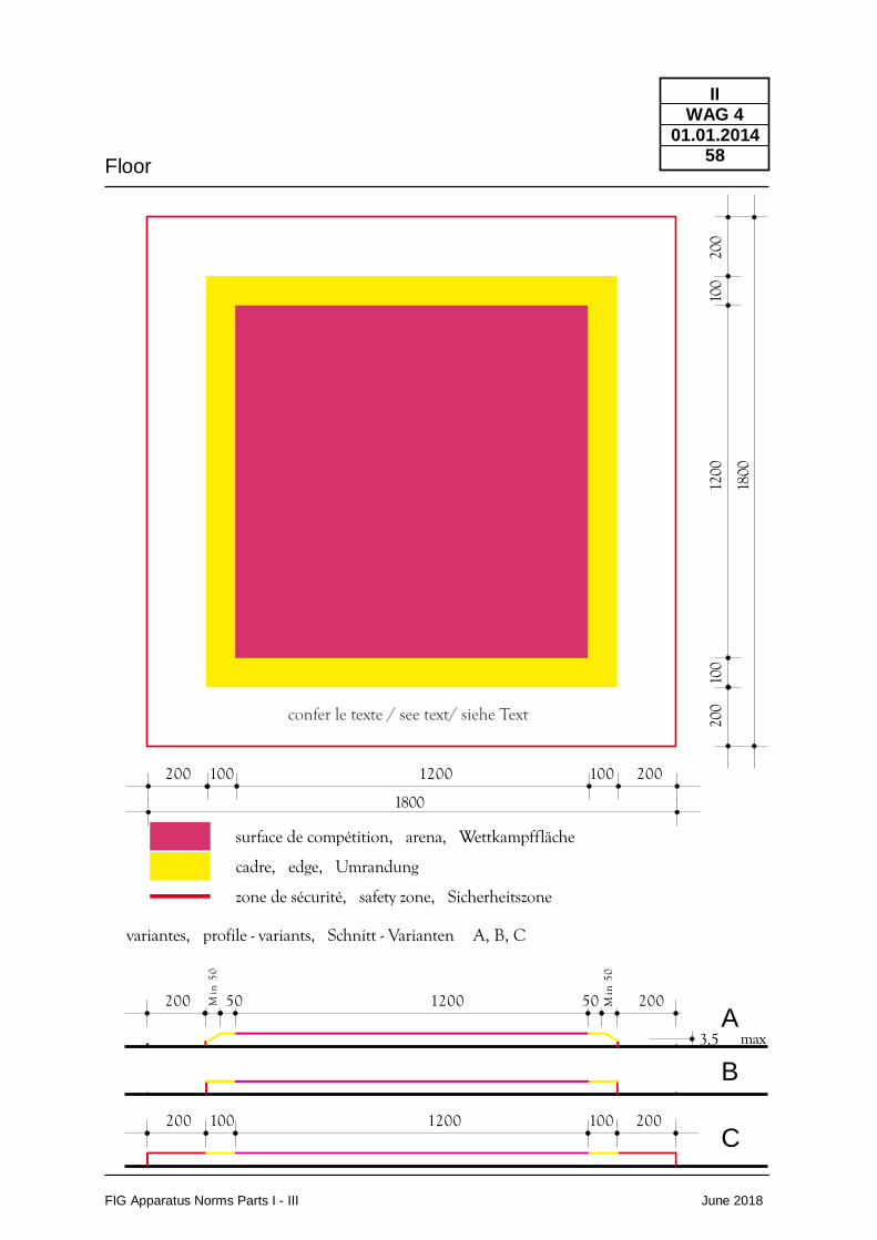
The Performance Area shall have a square format. The surface must be horizontal, even and without gaps. All plates of the under construction within the Performance Area shall have the same arrangement of elastic elements. All elements of the floor have to be connected firmly to prevent slipping. Border: Horizontal and even, at the same height as the surrounding performance area. Border, variation : Width 50 cm, horizontal and even, at the same height as the performance area, additional 50 cm inclination border, slope may not exceed 25 %. Safety zone: The safety zone shall be kept totally free as a surrounding zone around the performance area and the border. It shall be horizontal, even and without gaps. Performance area 1200 cm x 1200 cm Tolerance +/- 3 cm Diagonals of the performance area: 1697 cm +/- 5cm Border 100 cm, min. Border as a variant Horizontal part, width 50 cm, min. Slope max. 25 %, width 50 cm, min. Height of outer border 3,5 cm, max. When there is an delimitation strip between the performance area and the border: Width of the delimitation strip 5 cm +/- 0,5 cm The delimitation strip is part of the performance area. Performance area and border : - Equal elasticity and absorbency. - While in use, no counter swings must be produced. - Elasticity and absorbency of the floor must be balanced in such a way, that they guarantee the gymnast stability and freedom of movement. They must not restrict turns and slide movements. - The surface cover of the performance area must provide a balance between anti-skid and slippage. It must not cause skin burns. - The floor must not produce disturbing sounds. It must assure a low noise level. Plain colour, left to the discretion of the manufacturer. Dark colours are not allowed. For certain events the FIG may stipulate the colour. The delimitation shall have a clear contrast to the performance area.
Norms / Functional properties Regarding tests carried out by FIG Tests Institutes : please see chapter IV
Floor
FIG Apparatus Norms Parts I - III June 2018
II WAG 4
01.01.2014 58
200 100 1200 100 200
200 100 1200 100 200
200 50 1200 50 200
1800
surface de compétition, arena, Wettkampffläche
cadre, edge, Umrandung
zone de sécurité, safety zone, Sicherheitszone
variantes, profile - variants, Schnitt - Varianten A, B, C
200
100
1200
100
200
1800
3,5 max
confer le texte / see text/ siehe Text
Min
50
Min
50
A
B
C
Landing Mats
FIG Apparatus Norms Parts I - III June 2018
II WAG 11
1.06.2018 59
Use • Women’s Artistic Gymnastics
Construction / Description of material, measurements
Form
Measurements
Functional Properties
Colour
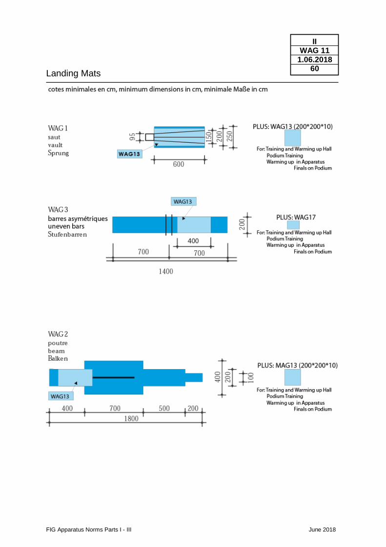
Their upper surface must be horizontal, even and without gaps. Specially designed mats must be used to cover the basis of the apparatus evenly.
Height of landing mats (WAG1, WAG2, WAG3): 20 cm +/- 1 cm Width and length see drawing
Absorbency: The mats must absorb motion energy, in order to reduce the reaction transmitted to the body of the landing gymnast, to a tolerable proportion. They must respond to increased penetration with an evenly increasing resistance. Stability and Freedom of Movement : Absorbency of the mats must be balanced in order to guarantee standing, walking stability and freedom of movement, there must be an equal balance between elasticity and absorbency properties. Indentations caused by the incidence of compressive forces must not encase the body parts, thereby hindering freedom of movements mainly of rolling a part of the body. If a cover is used, such cover may not cause hindering folds. The mats' upper surface material must offer a balance between anti-slip and slippage. It must be neither slippery nor possess inhibitory resistance. By no means should mats be dislocated during performances. An anti-skid cover on the mats' underside may provide this condition. The border zones of the mats which are pushed together should practically have the same functional properties as the remaining surface. Impacts on the border zones should not cause different indentations than on the remaining surface. For this purpose, and to bridge joints, continuous runners are permitted.
Preference should be given to uniform colours. The upper surface must not show optically disturbing patterns or insignia. The FIG may designate the colour of certain events.
Norms / Functional properties Regarding tests carried out by FIG Tests Institutes : please see chapter IV
Landing Mats
FIG Apparatus Norms Parts I - III June 2018
II WAG 11
1.06.2018 60
Supplementary Mats
FIG Apparatus Norms Parts I - III June 2018
II WAG 13
01.01.2017 61
Use • Women‘s Artistic Gymnastics
Construction / Description of material, measurements
Use
Form
Measurements
Functional Properties
Colour
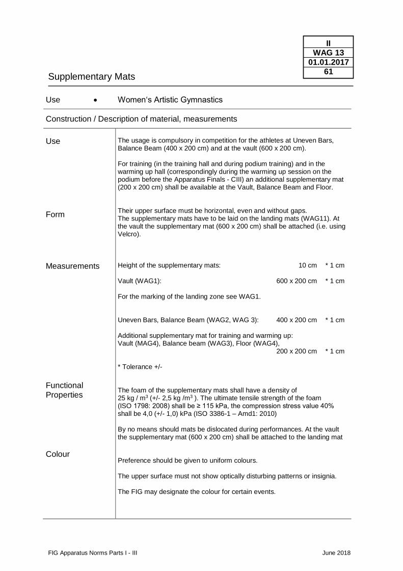
The usage is compulsory in competition for the athletes at Uneven Bars, Balance Beam (400 x 200 cm) and at the vault (600 x 200 cm). For training (in the training hall and during podium training) and in the warming up hall (correspondingly during the warming up session on the podium before the Apparatus Finals - CIII) an additional supplementary mat (200 x 200 cm) shall be available at the Vault, Balance Beam and Floor. Their upper surface must be horizontal, even and without gaps. The supplementary mats have to be laid on the landing mats (WAG11). At the vault the supplementary mat (600 x 200 cm) shall be attached (i.e. using Velcro). Height of the supplementary mats: 10 cm * 1 cm Vault (WAG1): 600 x 200 cm * 1 cm For the marking of the landing zone see WAG1. Uneven Bars, Balance Beam (WAG2, WAG 3): 400 x 200 cm * 1 cm Additional supplementary mat for training and warming up: Vault (MAG4), Balance beam (WAG3), Floor (WAG4), 200 x 200 cm * 1 cm * Tolerance +/- The foam of the supplementary mats shall have a density of 25 kg / m3 (+/- 2,5 kg /m3 ). The ultimate tensile strength of the foam (ISO 1798: 2008) shall be ≥ 115 kPa, the compression stress value 40% shall be 4,0 (+/- 1,0) kPa (ISO 3386-1 – Amd1: 2010) By no means should mats be dislocated during performances. At the vault the supplementary mat (600 x 200 cm) shall be attached to the landing mat Preference should be given to uniform colours. The upper surface must not show optically disturbing patterns or insignia. The FIG may designate the colour for certain events.
Vaulting Board
FIG Apparatus Norms Parts I - III June 2018
II WAG 14
01.01.2016 62
Use • Women’s Artistic Gymnastics - Vault (WAG1) – “hard” and “soft” - Uneven bars (WAG2) – “soft” - Balance beam (WAG3) – “soft”
Construction / Description of material, measurements
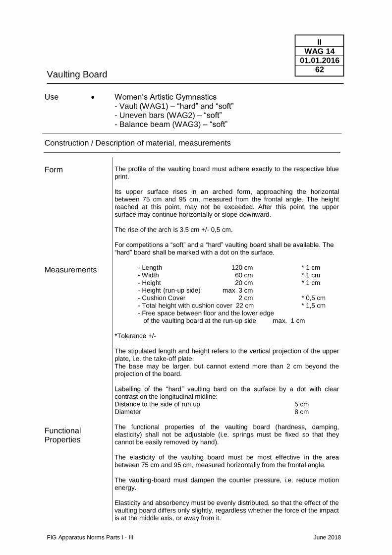
Form
Measurements
Functional Properties
The profile of the vaulting board must adhere exactly to the respective blue print. Its upper surface rises in an arched form, approaching the horizontal between 75 cm and 95 cm, measured from the frontal angle. The height reached at this point, may not be exceeded. After this point, the upper surface may continue horizontally or slope downward. The rise of the arch is 3.5 cm +/- 0,5 cm. For competitions a “soft” and a “hard” vaulting board shall be available. The “hard” board shall be marked with a dot on the surface. - Length 120 cm * 1 cm - Width 60 cm * 1 cm - Height 20 cm * 1 cm - Height (run-up side) max 3 cm - Cushion Cover 2 cm * 0,5 cm - Total height with cushion cover 22 cm * 1,5 cm - Free space between floor and the lower edge of the vaulting board at the run-up side max. 1 cm *Tolerance +/- The stipulated length and height refers to the vertical projection of the upper plate, i.e. the take-off plate. The base may be larger, but cannot extend more than 2 cm beyond the projection of the board. Labelling of the “hard” vaulting bard on the surface by a dot with clear contrast on the longitudinal midline: Distance to the side of run up 5 cm Diameter 8 cm The functional properties of the vaulting board (hardness, damping, elasticity) shall not be adjustable (i.e. springs must be fixed so that they cannot be easily removed by hand). The elasticity of the vaulting board must be most effective in the area between 75 cm and 95 cm, measured horizontally from the frontal angle. The vaulting-board must dampen the counter pressure, i.e. reduce motion energy. Elasticity and absorbency must be evenly distributed, so that the effect of the vaulting board differs only slightly, regardless whether the force of the impact is at the middle axis, or away from it.
Vaulting Board
FIG Apparatus Norms Parts I - III June 2018
II WAG 14
01.01.2016 63
Colour
The upper surface of the vaulting board must offer slip resistance. The vaulting board must not produce disturbing sounds during its use. The board shall not slide at the time of impact of the athlete. This shall be achieved by anti-slip devices at the bottom side of the board or at the board underneath the vaulting board. The slip resistance shall be provided especially when the board bottoms out at the middle part. The vaulting board and its base may not have any sharp corners, edges and no protruding parts. Mainly the upper and under edge of the upper part of the Vaulting board towards the apparatus side (Vaulting Table, Balance Beam or Uneven Bars) shall be cushioned and rounded. The choice of colour is left to the discretion of the manufacturer. With exception of the dot for “hard” vaulting boards optically disturbing patterns, stripes or insignia on the upper surface are not permitted. The FIG may designate the colour for certain events.
Norms / Functional properties Regarding tests carried out by FIG Tests Institutes : please see chapter IV
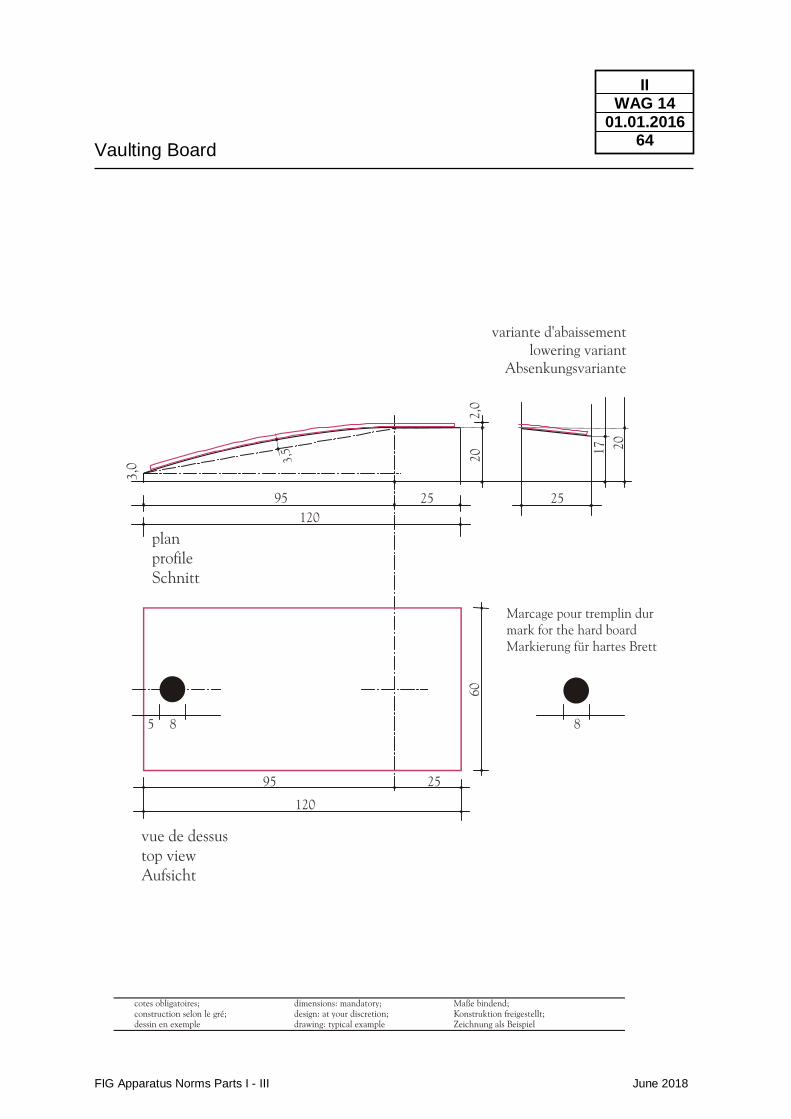
Vaulting Board
FIG Apparatus Norms Parts I - III June 2018
II WAG 14
01.01.2016 64
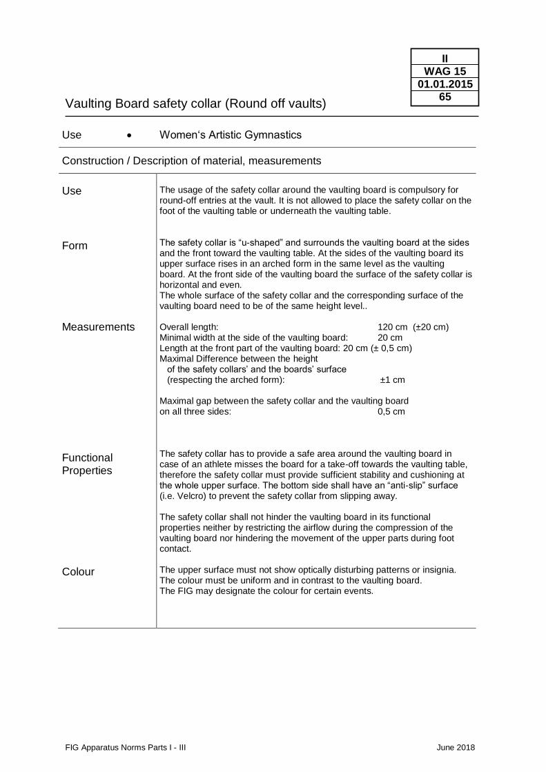
Vaulting Board safety collar (Round off vaults)
FIG Apparatus Norms Parts I - III June 2018
II WAG 15
01.01.2015 65
Use • Women‘s Artistic Gymnastics
Construction / Description of material, measurements
Use
Form
Measurements
Functional Properties
Colour
The usage of the safety collar around the vaulting board is compulsory for round-off entries at the vault. It is not allowed to place the safety collar on the foot of the vaulting table or underneath the vaulting table. The safety collar is “u-shaped” and surrounds the vaulting board at the sides and the front toward the vaulting table. At the sides of the vaulting board its upper surface rises in an arched form in the same level as the vaulting board. At the front side of the vaulting board the surface of the safety collar is horizontal and even. The whole surface of the safety collar and the corresponding surface of the vaulting board need to be of the same height level.. Overall length: 120 cm (±20 cm) Minimal width at the side of the vaulting board: 20 cm Length at the front part of the vaulting board: 20 cm (± 0,5 cm) Maximal Difference between the height of the safety collars’ and the boards’ surface (respecting the arched form): ±1 cm Maximal gap between the safety collar and the vaulting board on all three sides: 0,5 cm The safety collar has to provide a safe area around the vaulting board in case of an athlete misses the board for a take-off towards the vaulting table, therefore the safety collar must provide sufficient stability and cushioning at the whole upper surface. The bottom side shall have an “anti-slip” surface (i.e. Velcro) to prevent the safety collar from slipping away. The safety collar shall not hinder the vaulting board in its functional properties neither by restricting the airflow during the compression of the vaulting board nor hindering the movement of the upper parts during foot contact. The upper surface must not show optically disturbing patterns or insignia. The colour must be uniform and in contrast to the vaulting board. The FIG may designate the colour for certain events.
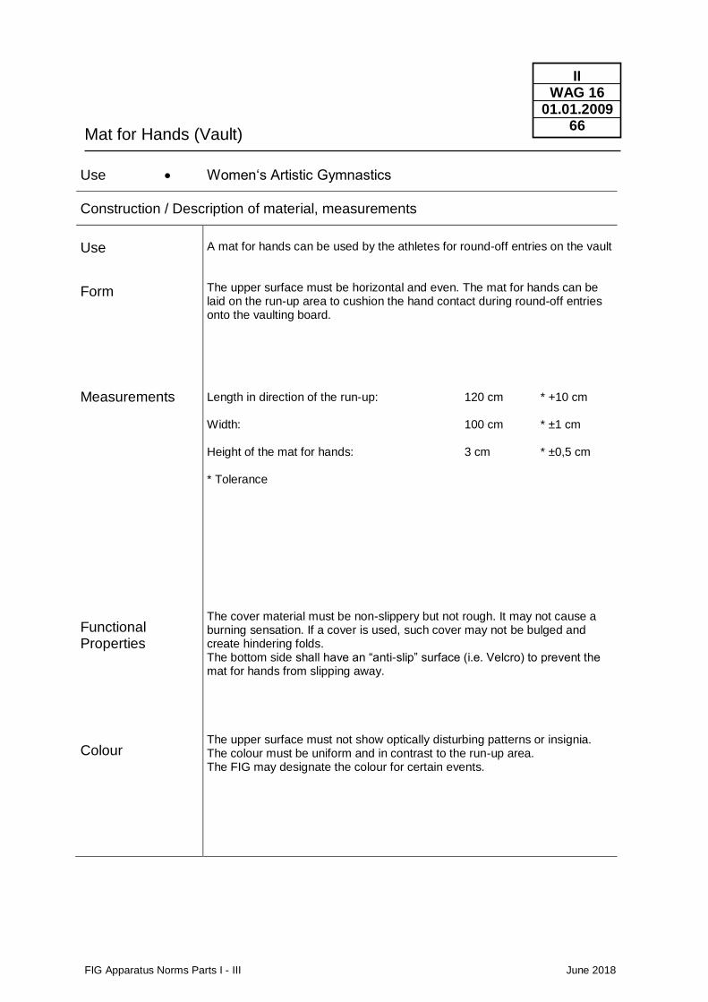
Mat for Hands (Vault)
FIG Apparatus Norms Parts I - III June 2018
II WAG 16
01.01.2009 66
Use • Women‘s Artistic Gymnastics
Construction / Description of material, measurements
Use
Form
Measurements
Functional Properties
Colour
A mat for hands can be used by the athletes for round-off entries on the vault The upper surface must be horizontal and even. The mat for hands can be laid on the run-up area to cushion the hand contact during round-off entries onto the vaulting board. Length in direction of the run-up: 120 cm * +10 cm Width: 100 cm * ±1 cm Height of the mat for hands: 3 cm * ±0,5 cm * Tolerance The cover material must be non-slippery but not rough. It may not cause a burning sensation. If a cover is used, such cover may not be bulged and create hindering folds. The bottom side shall have an “anti-slip” surface (i.e. Velcro) to prevent the mat for hands from slipping away. The upper surface must not show optically disturbing patterns or insignia. The colour must be uniform and in contrast to the run-up area. The FIG may designate the colour for certain events.
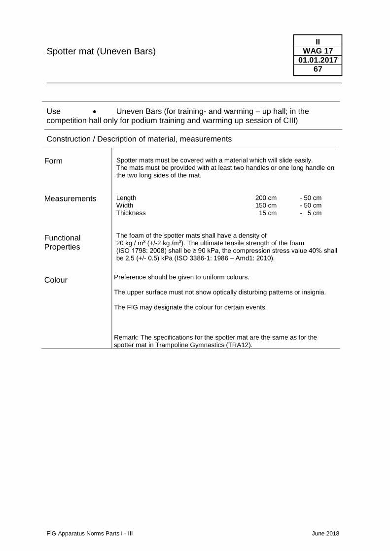
Spotter mat (Uneven Bars)
FIG Apparatus Norms Parts I - III June 2018
II WAG 17
01.01.2017 67
Use • Uneven Bars (for training- and warming – up hall; in the competition hall only for podium training and warming up session of CIII)
Construction / Description of material, measurements
Form
Measurements
Functional Properties
Colour
Spotter mats must be covered with a material which will slide easily. The mats must be provided with at least two handles or one long handle on the two long sides of the mat. Length 200 cm - 50 cm Width 150 cm - 50 cm Thickness 15 cm - 5 cm The foam of the spotter mats shall have a density of 20 kg / m3 (+/-2 kg /m3). The ultimate tensile strength of the foam (ISO 1798: 2008) shall be ≥ 90 kPa, the compression stress value 40% shall be 2,5 (+/- 0.5) kPa (ISO 3386-1: 1986 – Amd1: 2010).
Preference should be given to uniform colours. The upper surface must not show optically disturbing patterns or insignia. The FIG may designate the colour for certain events. Remark: The specifications for the spotter mat are the same as for the spotter mat in Trampoline Gymnastics (TRA12).
FIG Apparatus Norms Parts I - III June 2018
II RG
01.01.2014 68
2.3 RG Rhythmic gymnastics
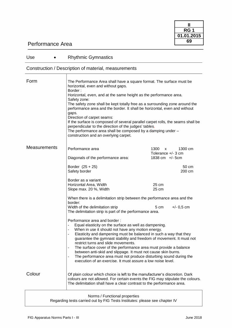
Performance Area
FIG Apparatus Norms Parts I - III June 2018
II RG 1
01.01.2015 69
Use • Rhythmic Gymnastics
Construction / Description of material, measurements
Form
Measurements
Colour
The Performance Area shall have a square format. The surface must be horizontal, even and without gaps. Border : Horizontal, even, and at the same height as the performance area. Safety zone: The safety zone shall be kept totally free as a surrounding zone around the performance area and the border. It shall be horizontal, even and without gaps. Direction of carpet seams: If the surface is composed of several parallel carpet rolls, the seams shall be perpendicular to the direction of the judges’ tables. The performance area shall be composed by a damping under – construction and an overlying carpet. Performance area 1300 x 1300 cm Tolerance +/- 3 cm Diagonals of the performance area: 1838 cm +/- 5cm Border (25 + 25) 50 cm Safety border 200 cm Border as a variant Horizontal Area, Width 25 cm Slope max. 20 %, Width 25 cm When there is a delimitation strip between the performance area and the border: Width of the delimitation strip 5 cm +/- 0,5 cm The delimitation strip is part of the performance area. Performance area and border : - Equal elasticity on the surface as well as dampening. - When in use it should not have any motion energy. - Elasticity and dampening must be balanced in such a way that they
guarantee the gymnast stability and freedom of movement. It must not restrict turns and slide movements.
- The surface cover of the performance area must provide a balance between anti-skid and slippage. It must not cause skin burns.
- The performance area must not produce disturbing sound during the execution of an exercise. It must assure a low noise level.
Of plain colour which choice is left to the manufacturer‘s discretion. Dark colours are not allowed. For certain events the FIG may stipulate the colours. The delimitation shall have a clear contrast to the performance area.
Norms / Functional properties Regarding tests carried out by FIG Tests Institutes: please see chapter IV
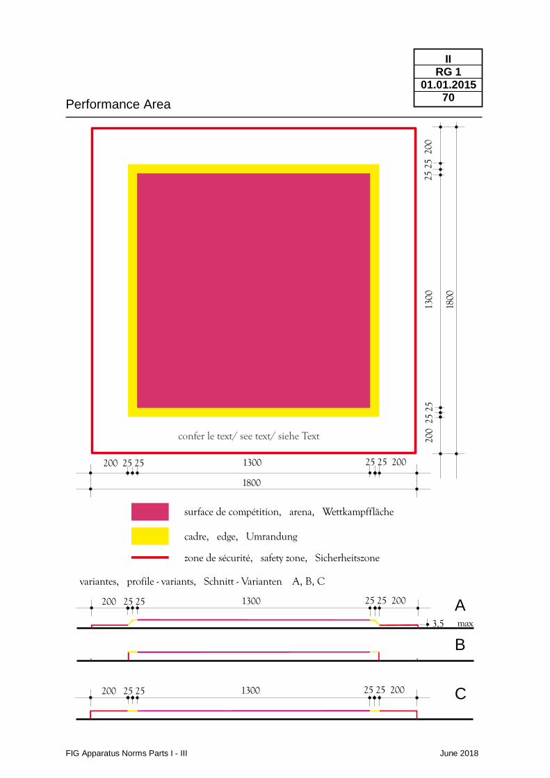
Performance Area
FIG Apparatus Norms Parts I - III June 2018
II RG 1
01.01.2015 70
25 25 2001300200 25 25
25 25 2001300200 25 25
25 25 2001300200 25 25
2525
200
200
2525
1300
1800
1800
cadre, edge, Umrandung
surface de compétition, arena, Wettkampffläche
zone de sécurité, safety zone, Sicherheitszone
variantes, profile - variants, Schnitt - Varianten A, B, C
3,5 max
confer le text/ see text/ siehe Text
A
B
C
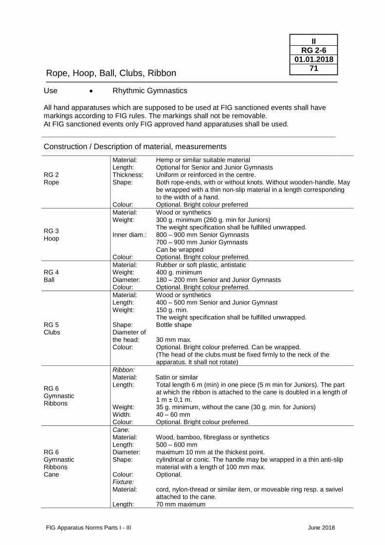
Rope, Hoop, Ball, Clubs, Ribbon
FIG Apparatus Norms Parts I - III June 2018
II RG 2-6
01.01.2018 71
Use • Rhythmic Gymnastics All hand apparatuses which are supposed to be used at FIG sanctioned events shall have markings according to FIG rules. The markings shall not be removable. At FIG sanctioned events only FIG approved hand apparatuses shall be used.
Construction / Description of material, measurements
RG 2 Rope
Material: Hemp or similar suitable material Length: Optional for Senior and Junior Gymnasts Thickness: Uniform or reinforced in the centre. Shape: Both rope-ends, with or without knots. Without wooden-handle. May
be wrapped with a thin non-slip material in a length corresponding to the width of a hand.
Colour: Optional. Bright colour preferred
RG 3 Hoop
Material: Wood or synthetics Weight: 300 g. minimum (260 g. min for Juniors) The weight specification shall be fulfilled unwrapped. Inner diam.: 800 – 900 mm Senior Gymnasts 700 – 900 mm Junior Gymnasts Can be wrapped Colour: Optional. Bright colour preferred.
RG 4 Ball
Material: Rubber or soft plastic, antistatic Weight: 400 g. minimum Diameter: 180 – 200 mm Senior and Junior Gymnasts Colour: Optional. Bright colour preferred.
RG 5 Clubs
Material: Wood or synthetics Length: 400 – 500 mm Senior and Junior Gymnast Weight: 150 g. min. The weight specification shall be fulfilled unwrapped. Shape: Bottle shape Diameter of the head: 30 mm max. Colour: Optional. Bright colour preferred. Can be wrapped. (The head of the clubs must be fixed firmly to the neck of the apparatus. It shall not rotate)
RG 6 Gymnastic Ribbons
Ribbon: Material: Satin or similar Length: Total length 6 m (min) in one piece (5 m min for Juniors). The part
at which the ribbon is attached to the cane is doubled in a length of 1 m ± 0,1 m.
Weight: 35 g. minimum, without the cane (30 g. min. for Juniors) Width: 40 – 60 mm Colour: Optional. Bright colour preferred.
RG 6 Gymnastic Ribbons Cane
Cane: Material: Wood, bamboo, fibreglass or synthetics Length: 500 – 600 mm Diameter: maximum 10 mm at the thickest point. Shape: cylindrical or conic. The handle may be wrapped in a thin anti-slip material with a length of 100 mm max. Colour: Optional. Fixture: Material: cord, nylon-thread or similar item, or moveable ring resp. a swivel attached to the cane. Length: 70 mm maximum
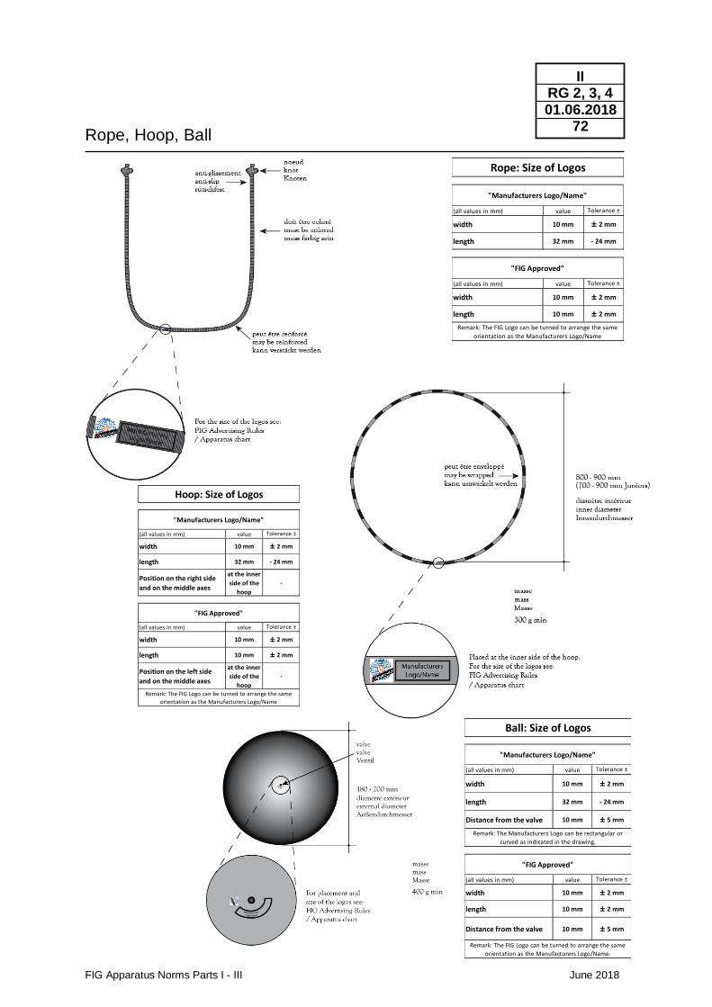
Rope, Hoop, Ball
FIG Apparatus Norms Parts I - III June 2018
II RG 2, 3, 4 01.06.2018
72
(all values in mm) value Tolerance ±
width 10 mm ± 2 mm
length 32 mm - 24 mm
Position on the right side
and on the middle axes
at the inner
side of the
hoop
-
(all values in mm) value Tolerance ±
width 10 mm ± 2 mm
length 10 mm ± 2 mm
Position on the left side
and on the middle axes
at the inner
side of the
hoop
-
Hoop: Size of Logos
"Manufacturers Logo/Name"
"FIG Approved"
Remark: The FIG Logo can be turned to arrange the same
orientation as the Manufacturers Logo/Name
(all values in mm) value Tolerance ±
width 10 mm ± 2 mm
length 32 mm - 24 mm
Distance from the valve 10 mm ± 5 mm
(all values in mm) value Tolerance ±
width 10 mm ± 2 mm
length 10 mm ± 2 mm
Distance from the valve 10 mm ± 5 mm
Ball: Size of Logos
"Manufacturers Logo/Name"
"FIG Approved"
Remark: The FIG Logo can be turned to arrange the same
orientation as the Manufacturers Logo/Name.
Remark: The Manufacturers Logo can be rectangular or
curved as indicated in the drawing.
(all values in mm) value Tolerance ±
width 10 mm ± 2 mm
length 32 mm - 24 mm
(all values in mm) value Tolerance ±
width 10 mm ± 2 mm
length 10 mm ± 2 mm
Rope: Size of Logos
"Manufacturers Logo/Name"
"FIG Approved"
Remark: The FIG Logo can be turned to arrange the same
orientation as the Manufacturers Logo/Name
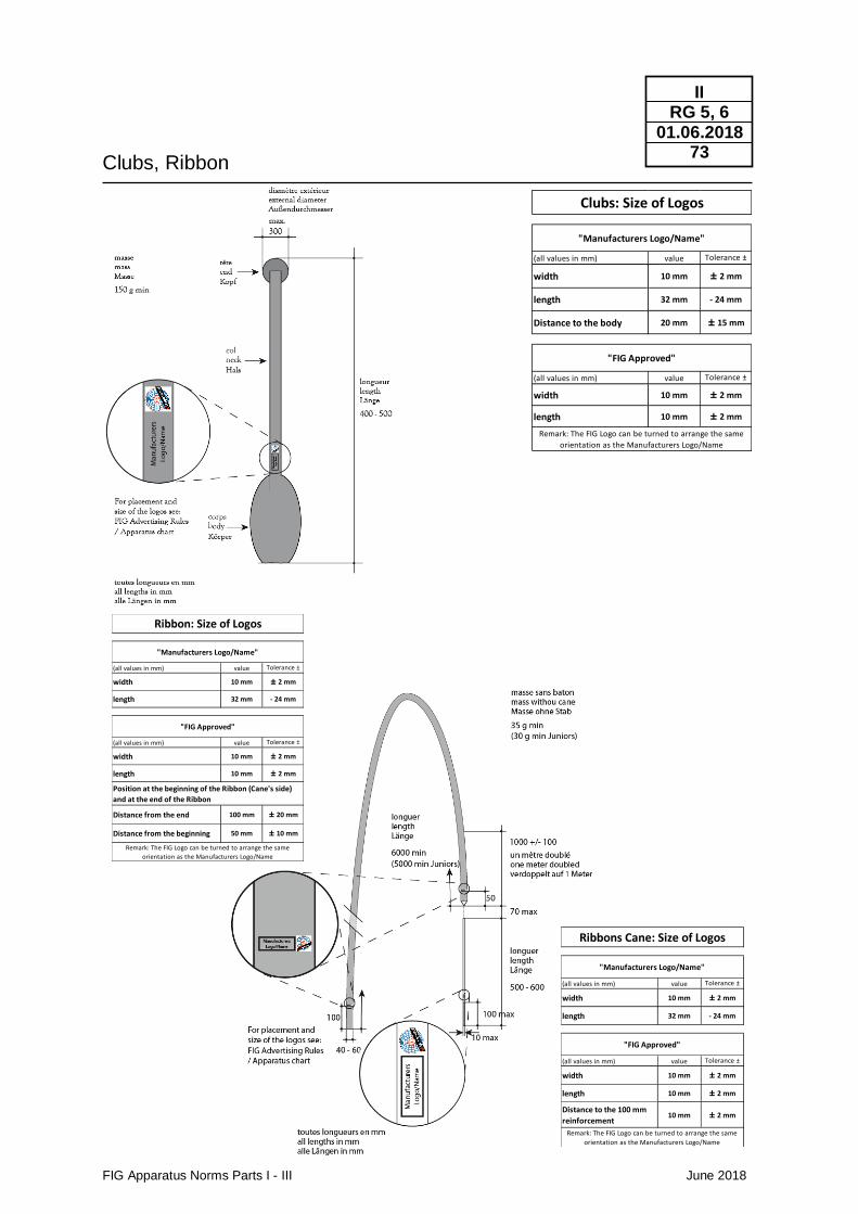
Clubs, Ribbon
FIG Apparatus Norms Parts I - III June 2018
II RG 5, 6
01.06.2018 73
(all values in mm) value Tolerance ±
width 10 mm ± 2 mm
length 32 mm - 24 mm
Distance to the body 20 mm ± 15 mm
(all values in mm) value Tolerance ±
width 10 mm ± 2 mm
length 10 mm ± 2 mm
Clubs: Size of Logos
"Manufacturers Logo/Name"
"FIG Approved"
Remark: The FIG Logo can be turned to arrange the same
orientation as the Manufacturers Logo/Name
(all values in mm) value Tolerance ±
width 10 mm ± 2 mm
length 32 mm - 24 mm
(all values in mm) value Tolerance ±
width 10 mm ± 2 mm
length 10 mm ± 2 mm
Distance from the end 100 mm ± 20 mm
Distance from the beginning 50 mm ± 10 mm
Ribbon: Size of Logos
"Manufacturers Logo/Name"
"FIG Approved"
Remark: The FIG Logo can be turned to arrange the same
orientation as the Manufacturers Logo/Name
Position at the beginning of the Ribbon (Cane's side)
and at the end of the Ribbon
(all values in mm) value Tolerance ±
width 10 mm ± 2 mm
length 32 mm - 24 mm
(all values in mm) value Tolerance ±
width 10 mm ± 2 mm
length 10 mm ± 2 mm
Distance to the 100 mm
reinforcement10 mm ± 2 mm
"Manufacturers Logo/Name"
Ribbons Cane: Size of Logos
"FIG Approved"
Remark: The FIG Logo can be turned to arrange the same
orientation as the Manufacturers Logo/Name
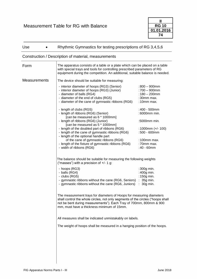
Measurement Table for RG with Balance
FIG Apparatus Norms Parts I - III June 2018
II RG 10
01.01.2016 74
Use • Rhythmic Gymnastics for testing prescriptions of RG 3,4,5,6
Construction / Description of material, measurements
Form
Measurements
The apparatus consists of a table or a plate which can be placed on a table with special trays and tools for controlling prescribed parameters of RG equipment during the competition. An additional, suitable balance is needed. The device should be suitable for measuring:
- interior diameter of hoops (RG3) (Senior) : 800 – 900mm - interior diameter of hoops (RG3) (Junior) : 700 – 900mm - diameter of balls (RG4) : 180 – 200mm - diameter of the end of clubs (RG5) : 30mm max. - diameter of the cane of gymnastic ribbons (RG6) : 10mm max.
- length of clubs (RG5) : 400 - 500mm - length of ribbons (RG6) (Senior) : 6000mm min.
[can be measured as 6 * 1000mm] - length of ribbons (RG6) (Junior) :5000mm min.
[can be measured as 5 * 1000mm] - length of the doubled part of ribbons (RG6) : 1000mm (+/- 100) - length of the cane of gymnastic ribbons (RG6) : 500 - 600mm - length of the optional handle part
of the cane of gymnastic ribbons (RG6) : 100mm max. - length of the fixture of gymnastic ribbons (RG6) : 70mm max. - width of ribbons (RG6) : 40 - 60mm
The The balance should be suitable for measuring the following weights (“masses”) with a precision of +/- 1 g:
- hoops (RG3) : 300g min. - balls (RG4) : 400g min. - clubs (RG5) : 150g min. - gymnastic ribbons without the cane (RG6, Seniors) : 35g min. - gymnastic ribbons without the cane (RG6, Juniors) : 30g min.
The measurement trays for diameters of Hoops for measuring diameters shall control the whole circles, not only segments of the circles (“hoops shall not be bent during measurements”). Each Tray of 700mm, 800mm & 900 mm, must have a thickness minimum of 15mm. All measures shall be indicated unmistakably on labels. The weight of hoops shall be measured in a hanging position of the hoops.
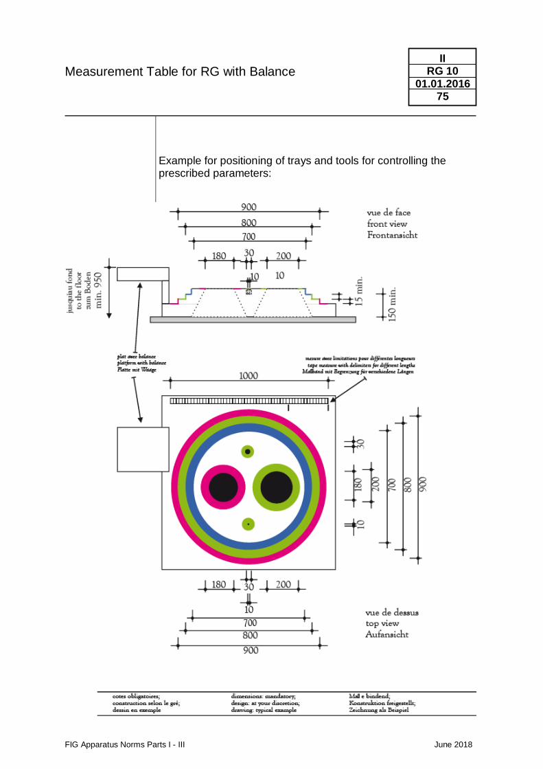
Measurement Table for RG with Balance
FIG Apparatus Norms Parts I - III June 2018
II RG 10
01.01.2016 75
Example for positioning of trays and tools for controlling the prescribed parameters:
FIG Apparatus Norms Parts I - III June 2018
II TRA
01.01.2014 76
2.4 TRA Trampoline Gymnastics
Trampoline
FIG Apparatus Norms Parts I - III June 2018
II TRA 1
01.01.2017 77
1. Frame 1.1. Interior measurements of the frame, with bed under tension, but without frame pads:
Length 505 cm +/-6 cm Width 291 cm +/-5 cm
1.2. For safety reasons the profile of the frame must have rounded edges. The radius must be min 15mm. The profile of the frame may also be oval or round, but in these cases, it must be guaranteed, that coaches are able to stand on the frame safely in order to give the necessary support to the athletes. Special attention must be given to the padding of the frame.
2. Trampoline Bed
2.1. The height of the bed, measured from the floor, shall meet all of the following three specifications:
2.1.1. At least one of the heights h1; h2; h3 or h4 (see figure) 115,5 cm +/-0,5 cm 2.1.2. All heights h1; h2; h3 and h4 (see figure) ≥ 115,0 cm
2.1.3. The heights h1; h2; h3 and h4 shall be adjusted, so that the bed is horizontal in all longitudinal and transversal directions with all four feet of the trampoline in firm contact to the ground.
2.2. Dimensions1 of the bed under tension ready for use, including attachment straps:
Length (bl1, bl2; bl3, see figure) 428 cm +/-6 cm with: max(bl1, bl2; bl3) – min(bl1, bl2; bl3) < 3 cm Width (bw1; bw2; bw3; see figure) 214 cm +/-5 cm with: max(bw1, bw2; bw3) – min(bw1, bw2; bw3) < 3 cm
2.3. The bed must be constructed from light coloured bands, webs, strings etc., which must be
held together in such a way that they are not displaced during use.
2.2.1. Web Construction: Width of web under tension 0,55 cm +/- 0,15 cm Distance between any two webs 1,6 cm (max.)
2.2.2. String Construction:
Width of strings under tension 0,3 cm +/- 0,1 cm Distance between any two strings no greater than 1 cm
2.4. The bed must be strong enough to withstand wear, and not tear when in use. 2.5. Two rectangular areas1 must be marked out clearly in red lines. Each area must be
symmetrically oriented to the middle of the bed. The width of the delimitation lines must be between 13 and 24 mm. The lines belong to the marked areas:
Area A (rectangle 215 * 108): - the delimitation lines for area A shall not only define the rectangle area of 215 * 108 cm, but shall also be continued to the end of the bed (see figure).
1 Trampoline beds are subject to considerable changes in dimensions due to the high tensions. All length specifications shall be fulfilled at the following instant of times: Competition: At the time of the officially announced apparatus control before the competitions and thereafter. During other official apparatus controls (i.e. test at a FIG test institute): After a period of 24h with the trampoline unfolded, ready for use and preconditioned with 20o ± 3o C and a humidity of < 60%.
Trampoline
FIG Apparatus Norms Parts I - III June 2018
II TRA 1
01.01.2017 78
Length (cl1, cl2, cl3, see figure) 215 +/- 4 cm with: max(cl1, cl2, cl3) – min(cl1, cl2, cl3) < 2 cm Width (dw1, dw2, dw3, see figure) 108 +/- 4 cm with: max(dw1, dw2, dw3) – min(dw1, dw2, dw3) < 2 cm Area B (quadratic 108 * 108): Length (el1, el2, el3, see figure) 108 +/- 4 cm with: max(el1, el2, el3) – min(el1, el2, el3) < 2 cm Width (dw1, dw2, dw3, see figure) 108 +/- 4 cm with: max(dw1, dw2, dw3) – min(dw1, dw2, dw3) < 2 cm The center of the bed must be indicated by a red cross.
Dimensions 70 cm +/- 3 cm
3. Suspension The bed must be suspended with springs in such a way as to present no danger to users. The tension on the bed should be such that the bed stabilises within a second after contact.
4. Area free of obstruction beneath the bed
The trampoline must be constructed so that the competitor will not touch any part of the frame beneath the bed.
5. Safety Padding
5.1. The frame and springs must be entirely covered by a shock absorbing padding, the thickness of which must be between 3,0 cm and 5,0 cm at the edge near the bed. At the edge over the frame the thickness must not be necessarily the same: It can increase up to 10 cm, however the maximum slope between the two edges shall not be higher than 10 degrees from horizontal plane. The padding must not touch any part of the bed. The padding may extend over the bed by up to 6 cm, but the available unobstructed jumping area may not be smaller than the minimum bed size (422 cm x 209 cm).
5.2. The padding should be firmly fixed to the frame without hindering the normal action of the bed and springs. It should not cause noise through flapping.
5.3. The bottom of the padding, at the side of the bed, should not protrude above the level of the bed by more than 6 cm. The padding must be stable enough to allow for a person to stand on it without protruding into the spaces between the springs.
5.4. The foam of the safety padding shall have a density of 30 kg / m3 (+/-3,0 kg /m3 ). The ultimate tensile strength of the foam (ISO 1798: 2008) shall be ≥ 260 kPa, the compression stress value 40% shall be 70,0 (+/- 15,0) kPa (ISO 3386-1 – Amd1: 2010).
6. Safety Platform
6.1. Platforms must be placed at both ends of the trampoline. The platform must be made of a framework which is firmly attached to the trampoline. The platforms must be constructed so that it is shock absorbent and the surface must be covered with a shock absorbing mat, firmly fixed to the platforms.
The mats must have the following dimensions: Width: 300 cm +/-2,5 cm Length (including wedge, 40 cm) 240 cm +/-2,5 cm Thickness at the bedside 7,5 cm +/-0,5 cm Thickness at the end 20 cm +/-2,0 cm The platforms dimensions must be such, that the mats are sufficiently supported to ensure, that on landing, it supports the weight of the competitor without collapsing or folding.
Trampoline
FIG Apparatus Norms Parts I - III June 2018
II TRA 1
01.01.2017 79
The foam of the mats shall have a density of 25 kg / m3 (+/-2,5 kg /m3 ). The ultimate tensile strength of the foam (ISO 1798: 2008) shall be ≥ 130 kPa, the compression stress value 40% shall be 4,0 (+/- 1,0) kPa (ISO 3386-1 – Amd1: 2010).
6.2. The mat covering the platform shall end between inner and outer edge of the frame pad.
The distance to the inner edge of the frame pad shall be 5 to 8 cm. (see figure) 7. Safety mats on the ground: Mats shall rest on the ground around and between the trampolines for
safety reasons. All mats shall be of the same height and type. One of the following two types shall be used: a) Mats which satisfy the specifications of MAG11/WAG11/TRA11. (measures: Height: 20 cm, Width: 200cm, Tolerance: +/- 1 cm). b) Mats with a core which shall have a density of 25 kg / m3 (+/-2,5 kg /m3 ). The ultimate tensile strength of the foam (ISO 1798: 2008) shall be ≥ 130 kPa, the compression stress value 40% shall be 4,0 (+/- 1,0) kPa (ISO 3386-1 – Amd1: 2010). Ultimate tensile strength (ISO 1798: 2008) of the cover material shall be 560-600 kPa. (measures: Height: 20 cm min , Width: 200cm, Tolerance: +/- 1 cm).
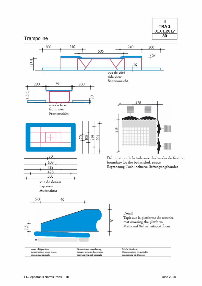
Trampoline
FIG Apparatus Norms Parts I - III June 2018
II TRA 1
01.01.2017 80
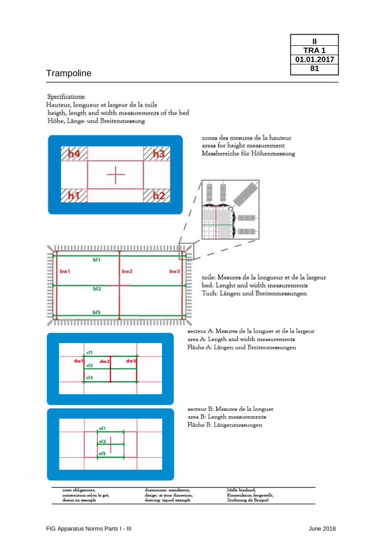
Trampoline
FIG Apparatus Norms Parts I - III June 2018
II TRA 1
01.01.2017 81
Double Mini - Trampoline
FIG Apparatus Norms Parts I - III June 2018
II TRA 2
01.01.2018 82
1. Frame
1.1. For safety reasons no metal bars or other firm fixings are allowed across the ends of the
Double Mini-Tramp other than at floor level. 1.2. For safety reasons the profile of the frame must have rounded edges. The radius must be
minimum 15mm. 1.3. Safety Padding
1.3.1. The frame and springs shall be entirely covered by shock absorbing padding, the
maximum Thickness of which shall be greater or equal 30mm and not be greater than 55mm. The padding must not cover any part of the bed.
1.3.2. The padding should be firmly fixed to the frame without hindering the normal
action of the bed and the springs. Nor should it cause noise through flapping. 1.3.3. The bottom of the padding at the side of the bed should not protrude above the
level of the bed by more than 6 cm. 1.3.4. The bars beneath the bed must be padded. 1.3.5. The frame ends on the dismount end must be covered with at least 50mm pads
firmly joined together with the other padding. 2. Bed
2.1. The bed must be constructed from light coloured bands, webs, strings etc., which must be
held together in such a way that they are not displaced during use. 2.2. Dimensions1 of the bed under tension
Length bl1; bl2; bl3 (see figure), edge to edge of included end markers 285 cm +/-5 cm with: max(bl1, bl2; bl3) – min(bl1, bl2; bl3) < 10 cm Width (bw1; bw2; bw3; see figure), including attachment straps: 92 cm +/-4 cm with: max(bw1, bw2; bw3) – min(bw1, bw2; bw3) < 2 cm
2.3. Height of bed, measured from the floor with bed under tension:
Mounting End 45 cm +/- 1,5 cm Dismounting End 70 cm +/- 1,5 cm
2.4. Width of web under tension: 0,4 cm min. 1,3 cm max.
Width of strings under tension: 0,3 cm +/- 0,1 cm 2.5. The strands of webbing (or string) must be sewn together, and the distance between any
two strands must not be greater than 1, 8 cm (max: 1 cm with string-construction). 2.6. The bed must be strong enough to withstand wear, and not tear when in use.
1 Double Mini Trampoline beds are subject to considerable changes in dimensions due to the high tensions. All length specifications shall be fulfilled at the following instant of times: Competition: At the time of the officially announced apparatus control before the competitions and thereafter. During other official apparatus controls (i.e. norm-control by TC members): After a period of 24h with the double mini trampoline unfolded, ready for use and preconditioned with 20o ± 3o C and a humidity of < 60%.
Double Mini - Trampoline
FIG Apparatus Norms Parts I - III June 2018
II TRA 2
01.01.2018 83
2.7. The Penalty Zones must be marked in red on the bed.
The dimensions of these zones are: End markers 13 cm +/- 2 cm Centre zone 39 cm +/- 1 cm Distance of the Centre Zone 90 cm +/- 2 cm (Measured from the mounting end)
3. Landing Area
3.1. The landing area shall be covered with a landing mat (TRA11) which is shock absorbent and which allows a stable landing on the feet. Dimensions of the landing area must be: Length (landing mat, TRA11) 600 cm +/- 1 cm Width (landing mat, TRA11) 300 cm +/- 1 cm Thickness (landing mat, TRA 11) 30 cm +/- 1 cm
3.2 Additional safety mat behind the landing area
An additional safety mat with the minimum dimensions of 300 * 200 * 20 cm must be placed directly behind the landing area.
3.3 Landing Zones
Two landing zones must be marked out in the landing area, with either the whole zone in a contrasting colour or, with lines 50mm wide in a contrasting colour. If lines are used, they have to belong to their zones.
3.3.1 Landing Zone C:
The size of landing zone C is identical to the size of the Landing Area (see 3.1 above)
3.3.2 Landing Zone B: The outer edge of the landing zone (or lines) marks the boundary of the landing zone, the dimensions of which must be: Length 400 cm +/- 1 cm Width 200 cm +/- 1 cm
3.3.3 Landing Zone A:
The outer edge of the landing zone (or lines) marks the boundary of the landing zone, the dimensions of which must be: Length 250 cm +/- 1 cm Width 100 cm +/- 1 cm
For certain events the FIG may stipulate the colours of the different zones.
4. Run-up
Floor mats shall be used on the run-up: Length 2000 cm + 250 cm Minimum Width 100 cm Thickness 2,5 cm +/-0,5 cm
5. Safety mats on the ground: On the two sides of the DMT a mat shall rest on the ground for safety reasons (measures: Height: 20 cm, Width: 200cm, Tolerance: +/- 1 cm). They have to satisfy the specifications of MAG11/WAG11/TRA11.
6. No testing procedures for Double Mini-Trampolines at a test institute are available at the moment. The test must be performed by a federation who qualified with a team for the Men´s Team Final in Double Mini-Trampoline at the last held World Championships. Further Procedures for Certification see Part III, 4.1. and 4.2.
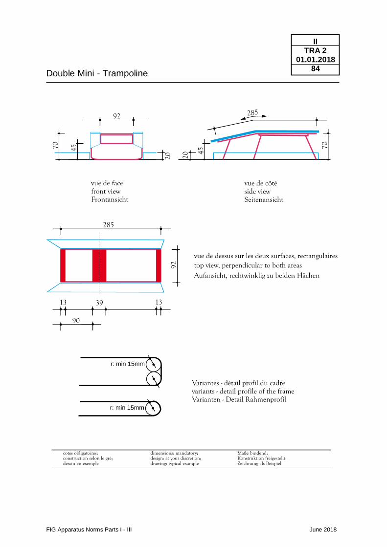
Double Mini - Trampoline
FIG Apparatus Norms Parts I - III June 2018
II TRA 2
01.01.2018 84
vue de facefront viewFrontansicht
Variantes - détail profil du cadrevariants - detail profile of the frameVarianten - Detail Rahmenprofil
vue de côtéside viewSeitenansicht
92 285
70 7045 45
2020
vue de dessus sur les deux surfaces, rectangulairestop view, perpendicular to both areasAufansicht, rechtwinklig zu beiden Flächen
Maße bindend;Konstruktion freigestellt;Zeichnung als Beispiel
cotes obligatoires;construction selon le gré;dessin en exemple
dimensions: mandatory;design: at your discretion;drawing: typical example
r: min 15mm
r: min 15mm
285
90
13 1339
92
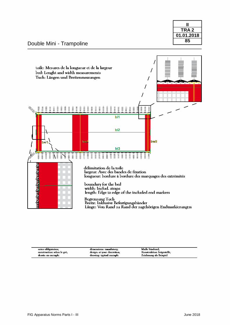
Double Mini - Trampoline
FIG Apparatus Norms Parts I - III June 2018
II TRA 2
01.01.2018 85
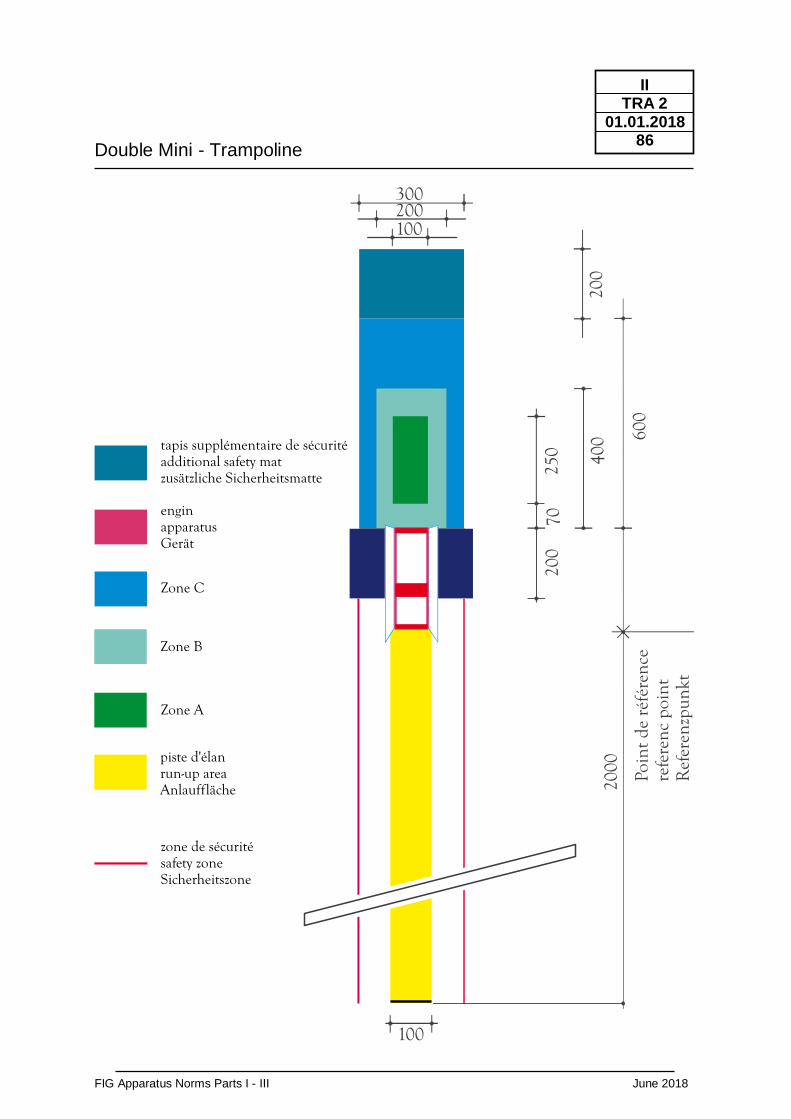
Double Mini - Trampoline
FIG Apparatus Norms Parts I - III June 2018
II TRA 2
01.01.2018 86
600
70
2000
enginapparatusGerät
Zone C
Zone B
Zone A
piste d'élanrun-up areaAnlauffläche
zone de sécuritésafety zoneSicherheitszone
100
300200100
Poin
tde
réfé
renc
ere
fere
ncpo
int
Ref
eren
zpun
kt
250 40
0
200
200
tapis supplémentaire de sécuritéadditional safety matzusätzliche Sicherheitsmatte
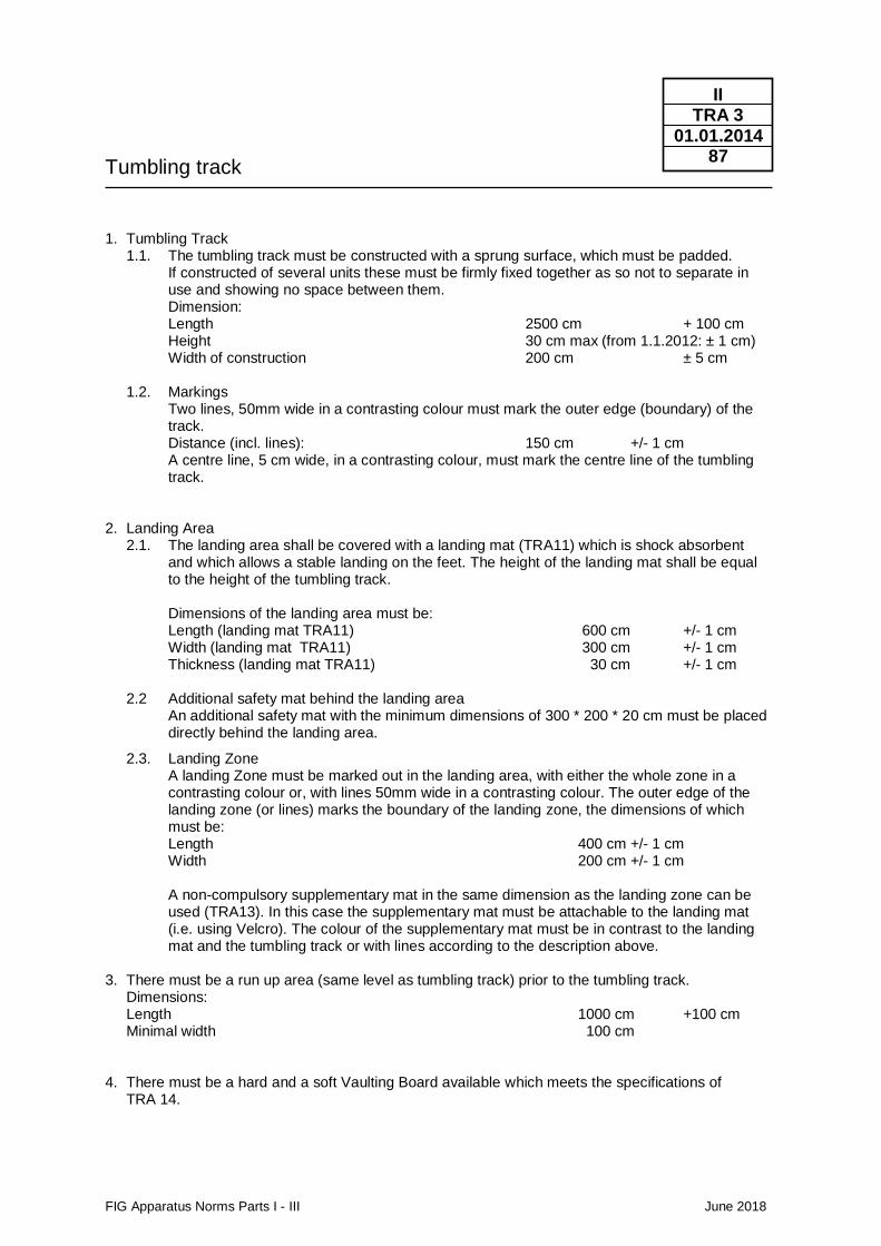
Tumbling track
FIG Apparatus Norms Parts I - III June 2018
II TRA 3
01.01.2014 87
1. Tumbling Track
1.1. The tumbling track must be constructed with a sprung surface, which must be padded. If constructed of several units these must be firmly fixed together as so not to separate in use and showing no space between them. Dimension: Length 2500 cm + 100 cm Height 30 cm max (from 1.1.2012: ± 1 cm) Width of construction 200 cm ± 5 cm
1.2. Markings Two lines, 50mm wide in a contrasting colour must mark the outer edge (boundary) of the track. Distance (incl. lines): 150 cm +/- 1 cm A centre line, 5 cm wide, in a contrasting colour, must mark the centre line of the tumbling track.
2. Landing Area
2.1. The landing area shall be covered with a landing mat (TRA11) which is shock absorbent and which allows a stable landing on the feet. The height of the landing mat shall be equal to the height of the tumbling track. Dimensions of the landing area must be: Length (landing mat TRA11) 600 cm +/- 1 cm Width (landing mat TRA11) 300 cm +/- 1 cm Thickness (landing mat TRA11) 30 cm +/- 1 cm
2.2 Additional safety mat behind the landing area An additional safety mat with the minimum dimensions of 300 * 200 * 20 cm must be placed directly behind the landing area.
2.3. Landing Zone
A landing Zone must be marked out in the landing area, with either the whole zone in a contrasting colour or, with lines 50mm wide in a contrasting colour. The outer edge of the landing zone (or lines) marks the boundary of the landing zone, the dimensions of which must be: Length 400 cm +/- 1 cm Width 200 cm +/- 1 cm A non-compulsory supplementary mat in the same dimension as the landing zone can be used (TRA13). In this case the supplementary mat must be attachable to the landing mat (i.e. using Velcro). The colour of the supplementary mat must be in contrast to the landing mat and the tumbling track or with lines according to the description above.
3. There must be a run up area (same level as tumbling track) prior to the tumbling track.
Dimensions: Length 1000 cm +100 cm Minimal width 100 cm
4. There must be a hard and a soft Vaulting Board available which meets the specifications of
TRA 14.
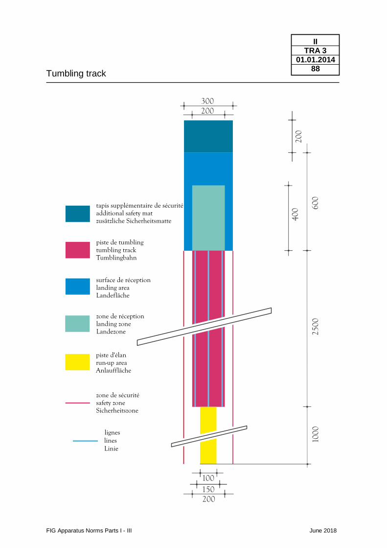
Tumbling track
FIG Apparatus Norms Parts I - III June 2018
II TRA 3
01.01.2014 88
600
2500
piste de tumblingtumbling trackTumblingbahn
piste d'élanrun-up areaAnlauffläche
zone de sécuritésafety zoneSicherheitszone
400
1000
300200
200
100150
lineslignes
Linie
surface de réceptionlanding areaLandefläche
zone de réceptionlanding zoneLandezone
200
tapis supplémentaire de sécuritéadditional safety matzusätzliche Sicherheitsmatte
Landing mat Double Mini-Trampoline + Tumbling Safety mat Trampoline, Double Mini-Trampoline
FIG Apparatus Norms Parts I - III June 2018
II TRA 11
01.01.2006 89
Use • Double Mini-Trampoline; Tumbling; Trampoline
Construction / Description of material, measurements
Form
Measurements
Functional Properties
Colour
The surface must be horizontal, even and without gaps. To arrange the whole area several mats can be composed. Height safety mat Trampoline; DMT (TRA1, TRA2): 20 cm +/- 1 cm Height landing mat DMT; Tumbling (TRA2, TRA3): 30 cm +/- 1 cm Absorbency: The mats must absorb motion energy, in order to reduce the reaction transmitted to the body of the landing gymnast, to a tolerable proportion. They must respond to increased penetration with an evenly increasing resistance. Stability and Freedom of Movement: Absorbency of the mats must be balanced in order to guarantee standing, walking stability and freedom of movement; there must be an equal balance between elasticity and absorbency properties. Indentations caused by the incidence of compressive forces must not encase the body parts, thereby hindering freedom of movements mainly of rolling a part of the body. If a cover is used, such cover may not cause any hindering folds. The mats' upper surface material must offer a balance between anti-slip and slippage. It must be neither slippery nor possess inhibitory resistance. By no means should mats be dislocated during performances. An anti-ski cover on the mats' underside may provide this condition. The border zones of the mats which are pushed together should practically have the same functional properties as the remaining surface. Impacts on the border zones should not cause different indentations than on the remaining surface. For this purpose, and to bridge joints, continuous runners are permitted. Preference should be given to uniform colours. The upper surface must not show optically disturbing patterns or insignia. The FIG may designate the colour for certain events.
Norms / Functional properties Regarding tests carried out by FIG Tests Institutes: please see chapter IV
Spotter mat Trampoline, Double Mini-Trampoline
FIG Apparatus Norms Parts I - III June 2018
II TRA 12
01.01.2016 90
Use • Trampoline; Double Mini-Trampoline
Construction / Description of material, measurements
Form
Measurements
Functional Properties
Colour
Spotter mats must be covered with a material which will slide easily. The mats must be provided with at least two handles or one long handle on the two long sides of the mat. Length 200 cm - 50 cm Width 150 cm - 50 cm Thickness 15 cm - 5 cm The foam of the spotter mats shall have a density of 20 kg / m3 (+/-2 kg /m3). The ultimate tensile strength of the foam (ISO 1798: 2008) shall be ≥ 90 kPa, the compression stress value 40% shall be 2,5 (+/- 0.5) kPa (ISO 3386-1: 1986 – Amd1: 2010).
Preference should be given to uniform colours. The upper surface must not show optically disturbing patterns or insignia. The FIG may designate the colour for certain events.
Supplementary mat Tumbling
FIG Apparatus Norms Parts I - III June 2018
II TRA 13
01.01.2016 91
Use • Tumbling
Construction / Description of material, measurements
Use
Form
Measurements
Functional Properties
Colour
A supplementary mat must be available for the landing area in Tumbling. The usage is not compulsory. Their upper surface must be horizontal, even and without gaps. It shall have the size of the landing zone. The supplementary mat can be laid on the landing mats (TRA11), if used it must be attachable to the landing mat (i.e. using Velcro). Height of the supplementary mat: 10 cm * 1 cm Surface: 400 x 200 cm * 1 cm * Tolerance +/- The foam of the supplementary mats shall have a density of 25 kg / m3 (+/- 2,5 kg /m3 ). The ultimate tensile strength of the foam (ISO 1798: 2008) shall be ≥ 115 kPa, the compression stress value 40% shall be 4,0 (+/- 1.0) kPa (ISO 3386-1: 1986 – Amd1: 2010). Their upper surface must be horizontal, even and without gaps. The supplementary mats have to be laid on the landing mats. The supplementary mat shall be attachable (i.e. using Velcro). The colour of the supplementary mat must be in contrast to the landing mat and the tumbling track or with lines according to the description of the landing zone (see TRA3). The upper surface must not show optically disturbing patterns or insignia. The FIG may designate the colour for certain events.
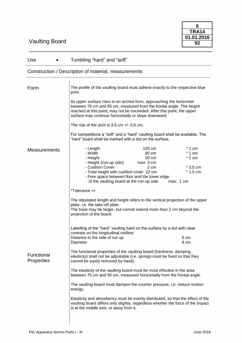
Vaulting Board
FIG Apparatus Norms Parts I - III June 2018
II TRA14
01.01.2016 92
Use • Tumbling “hard” and “soft”
Construction / Description of material, measurements
Form
Measurements
Functional Properties
The profile of the vaulting board must adhere exactly to the respective blue print. Its upper surface rises in an arched form, approaching the horizontal between 75 cm and 95 cm, measured from the frontal angle. The height reached at this point, may not be exceeded. After this point, the upper surface may continue horizontally or slope downward. The rise of the arch is 3.5 cm +/- 0,5 cm. For competitions a “soft” and a “hard” vaulting board shall be available. The “hard” board shall be marked with a dot on the surface. - Length 120 cm * 1 cm - Width 60 cm * 1 cm - Height 20 cm * 1 cm - Height (run-up side) max 3 cm - Cushion Cover 2 cm * 0,5 cm - Total height with cushion cover 22 cm * 1,5 cm - Free space between floor and the lower edge of the vaulting board at the run-up side max. 1 cm *Tolerance +/- The stipulated length and height refers to the vertical projection of the upper plate, i.e. the take-off plate. The base may be larger, but cannot extend more than 2 cm beyond the projection of the board. Labelling of the “hard” vaulting bard on the surface by a dot with clear contrast on the longitudinal midline: Distance to the side of run up 5 cm Diameter 8 cm The functional properties of the vaulting board (hardness, damping, elasticity) shall not be adjustable (i.e. springs must be fixed so that they cannot be easily removed by hand). The elasticity of the vaulting board must be most effective in the area between 75 cm and 95 cm, measured horizontally from the frontal angle. The vaulting-board must dampen the counter pressure, i.e. reduce motion energy. Elasticity and absorbency must be evenly distributed, so that the effect of the vaulting board differs only slightly, regardless whether the force of the impact is at the middle axis, or away from it.
Vaulting Board
FIG Apparatus Norms Parts I - III June 2018
II TRA14
01.01.2016 93
Colour
The upper surface of the vaulting board must offer slip resistance. The board must not produce disturbing sounds during its use. The board shall not slide at the time of impact of the athlete. This shall be achieved by anti-slip devices at the bottom side of the board. The slip resistance shall be provided especially when the board bottoms out at the middle part. The vaulting board and its base may not have any sharp corners, edges and no protruding parts. Mainly the upper and under edge of the upper part of the Vaulting board towards the apparatus side (Vaulting Table, Balance Beam of Uneven Bars) shall be cushioned and rounded. The choice of colour is left to the discretion of the manufacturer. With exception of the dot for “hard” vaulting boards optically disturbing patterns, stripes or insignia on the upper surface are not permitted. The FIG may designate the colour for certain events.
Norms / Functional properties Regarding tests carried out by FIG Tests Institutes: please see chapter IV
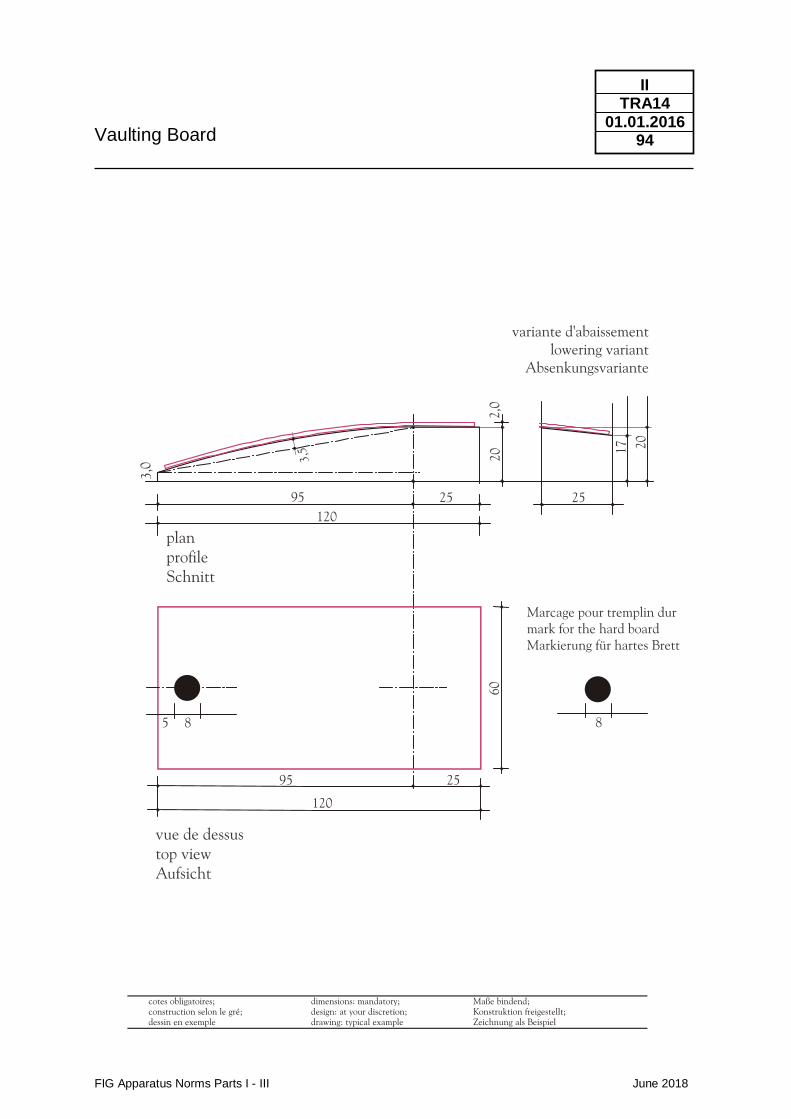
Vaulting Board
FIG Apparatus Norms Parts I - III June 2018
II TRA14
01.01.2016 94
Time measurement device for trampoline competitions - TMD
FIG Apparatus Norms Parts I - III June 2018
II TRA 15
01.06.2018 95
Use • Device for judging individual and synchronized competitions
Construction / Description of material
General Requirements
Variants General Functions
Definitions
The device must be able to measure a sum of the flight times for the skills in individual competitions as well as deductions due to asynchronous landing in synchronized competitions.
Different measuring methods result in two variants of the TMD:
Variant A:
Measurements up to 10 cm below the unloaded trampoline bed ( e.g. through photoelectric barriers along defined measurement lines).
Variant B:
Measurements relative to the unloaded surface of the trampoline bed. This variant can be used, for example, in combination with other measuring devices (HDMD - TRA 16).
1. Mode for individual competitions: The device is installed at the trampoline which is used for the competition. It has to be administrated by a specialized judge. After a “Start” during the flight phase of the first element the device shall register all time intervals between take-offs and the landings of the gymnast (flight times) including the flight time of the first element. At the end of the routine the device has to calculate, to indicate and to memorize the flight times of the elements as well as their sum (up to 10 skills).
2. Mode for synchronized competitions: The device is installed at the two trampolines which are used for the competition. It has to be administrated by a specialized judge who is responsible for the evaluation of the score of synchronization (S). After a “Start” during the flight phase of the first element the device shall register all time intervals between the landings of the gymnasts. After the end of the routine the device has to calculate, to indicate and to memorize the deductions for each skill and the total score for synchronization according to a conversion ratio between time intervals and deductions (TRA Code of Points).
Valid for TMD Variant A
Measurement Lines for Time of Flight and Synchronization Evaluation: At least three parallel lines along the longitudinal side of the trampoline’s bed. The lines are arranged ≤ 100 mm below the underside of the unloaded bed installed at a trampoline which is ready for use. One line (center line) shall be exactly below the longitudinal middle axis of the jumping zone and at least two others are running in a distance of 540 (±5)mm to the center of the bed directly below the lateral boundaries of the jumping zone (see drawing).
Starting point of the flight phase: The point in time of the release of the gymnast from all Measurement Lines by taking off from the trampoline’s bed. At that time a measurable signal for the TMD shall be provoked.
Time measurement device for trampoline competitions - TMD
FIG Apparatus Norms Parts I - III June 2018
II TRA 15
01.06.2018 96
Ending point of the flight phase: The point in time of the first contact of the gymnast with at least one of the Measurement Lines by impacting the trampoline’s bed. At that time a measurable signal for the TMD shall be provoked.
Time Difference in Landing: Time interval at the landing after the same synchronous jump between the Ending point of the flight phase of the first athlete and the Ending point of the flight phase of the second athlete, expressed in seconds rounded down to the next lower multiple of 0,005 s (e.g.: All values less than 0.005 s are rounded to 0.000 s, all values equal or higher than 0.005 s and less than 0.01 s are rounded to 0.005 s).
Valid for TMD Variant B
Measurement Plane for Time of Flight and Synchronization Evaluation: The surface of the unloaded trampoline’s bed.
Starting point of the flight phase: The point in time of the release of the gymnast from Measurement Plane by taking off to a flight phase.
Ending point of the flight phase: The point in time of the first contact of the gymnast with the Measurement Plane after a flight phase.
Time Difference in Landing: Time interval at the landing after the same synchronous jump between the Ending point of the flight phase of the first athlete and the Ending point of the flight phase of the second athlete, expressed in seconds rounded down to the next lower multiple of 0,005 s (e.g.: All values less than 0.005 s are rounded to 0.000 s, all values equal or higher than 0.005 s and less than 0.01 s are rounded to 0.005 s).
Time of Flight: Time interval during the flight phase of a jump between a Starting point of the flight phase and a succeeding Ending point of the flight phase, expressed in seconds rounded down to the next lower multiple of 0,005 s. (e.g.: All values less than 0.005 s are rounded to 0.000 s, all values equal or higher than 0.005 s and less than 0.01 s are rounded to 0.005 s).
Valid for TMD variants A and B
Time of Flight: Time interval during the flight phase of a jump between a Starting point of the flight phase and a succeeding Ending point of the flight phase, expressed in seconds rounded down to the next lower multiple of 0,005 s. (e.g.: All values less than 0.005 s are rounded to 0.000 s, all values equal or higher than 0.005 s and less than 0.01 s are rounded to 0.005 s).
Total Time of Flight: Sum of all measured Time of Flights during an exercise of an individual competition beginning with the first skill, expressed in seconds. This value in seconds is equivalent to the score for the total time of flight in points.
Start: The point in time fixed by a switch-key to be pressed by a specialized judge during the flight phase of the first element; from this time on the TMD records signals at landings of the athlete on the trampolines bed. For individual competitions the device has to remember the preceding Starting point of the flight phase to register the Time of Flight of the first element.
Stop: The point in time fixed by a switch-key to be pressed by a
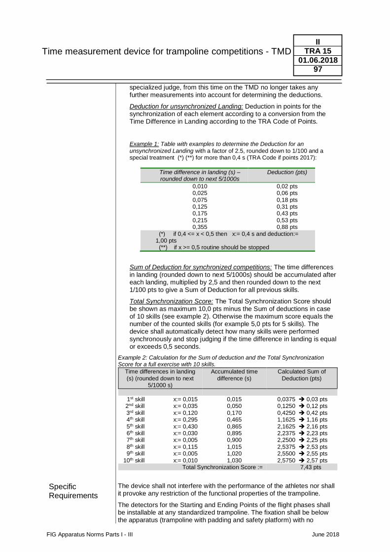
Time measurement device for trampoline competitions - TMD
FIG Apparatus Norms Parts I - III June 2018
II TRA 15
01.06.2018 97
Specific Requirements
specialized judge, from this time on the TMD no longer takes any further measurements into account for determining the deductions.
Deduction for unsynchronized Landing: Deduction in points for the synchronization of each element according to a conversion from the Time Difference in Landing according to the TRA Code of Points.
Example 1: Table with examples to determine the Deduction for an unsynchronized Landing with a factor of 2.5, rounded down to 1/100 and a special treatment (*) (**) for more than 0,4 s (TRA Code if points 2017):
Time difference in landing (s) – rounded down to next 5/1000s
Deduction (pts)
0,010 0,02 pts 0,025 0,06 pts 0,075 0,18 pts 0,125 0,31 pts 0,175 0,43 pts 0,215 0,53 pts 0,355 0,88 pts
(*) if 0,4 <= x < 0,5 then x:= 0,4 s and deduction:= 1,00 pts (**) if x >= 0,5 routine should be stopped
Sum of Deduction for synchronized competitions: The time differences in landing (rounded down to next 5/1000s) should be accumulated after each landing, multiplied by 2,5 and then rounded down to the next 1/100 pts to give a Sum of Deduction for all previous skills.
Total Synchronization Score: The Total Synchronization Score should be shown as maximum 10,0 pts minus the Sum of deductions in case of 10 skills (see example 2). Otherwise the maximum score equals the number of the counted skills (for example 5,0 pts for 5 skills). The device shall automatically detect how many skills were performed synchronously and stop judging if the time difference in landing is equal or exceeds 0,5 seconds.
Example 2: Calculation for the Sum of deduction and the Total Synchronization Score for a full exercise with 10 skills.
Time differences in landing (s) (rounded down to next
5/1000 s)
Accumulated time difference (s)
Calculated Sum of Deduction (pts)
1st skill x:= 0,015 0,015 0,0375 ➔ 0,03 pts 2nd skill x:= 0,035 0,050 0,1250 ➔ 0,12 pts 3rd skill x:= 0,120 0,170 0,4250 ➔ 0,42 pts 4th skill x:= 0,295 0,465 1,1625 ➔ 1,16 pts 5th skill x:= 0,430 0,865 2,1625 ➔ 2,16 pts 6th skill x:= 0,030 0,895 2,2375 ➔ 2,23 pts 7th skill x:= 0,005 0,900 2,2500 ➔ 2,25 pts 8th skill x:= 0,115 1,015 2,5375 ➔ 2,53 pts 9th skill x:= 0,005 1,020 2,5500 ➔ 2,55 pts 10th skill x:= 0,010 1,030 2,5750 ➔ 2,57 pts
Total Synchronization Score := 7,43 pts
The device shall not interfere with the performance of the athletes nor shall it provoke any restriction of the functional properties of the trampoline.
The detectors for the Starting and Ending Points of the flight phases shall be installable at any standardized trampoline. The fixation shall be below the apparatus (trampoline with padding and safety platform) with no
Time measurement device for trampoline competitions - TMD
FIG Apparatus Norms Parts I - III June 2018
II TRA 15
01.06.2018 98
Technical Features
protruding parts. If there are cable connections, they must be long enough to reach the displacement specifications given for the “Arena for Trampoline Competitions” (see: Part II 4. Competition area; TRA). All other components of the device shall be out of the area of the safety mats on the ground.
If emitters of sound, light or radio waves are used, they shall not harm participants, judges, spectators or other staff.
If the device needs external power, it must be provided with backup power, providing a battery life for at least 5 minutes after disconnecting the external power source.
The system must provide time measurements with an error lower than ± 0,005 s.
The TMD shall come with an English written documentation containing a user´s guide and all necessary technical descriptions.
The control device or the control of the computer-program shall contain a set of switches, indicators and components with the following features:
• SELECT MODE – individual or synchronized competition
• RESET – Preparation for a new measurement
• START– start the measurement of an exercise, indicated by a sound
• STOP – stop the measurement of an exercise
• VIEW – MODE – with the following possibilities: Synchronized competition mode: Selection for each skill (from 1 to 10) with the calculated deductions for unsynchronized landing as well as the Total Synchronization Score for the whole exercise. Individual competition mode: Selection for each skill (from 1 to 10) with the registered Times of Flight as well as the Total Time of Flight for the whole exercise.
• Possibilities for a manual change of the Preliminary Synchronization Score with an increment of 0,2 points.
• Components to ensure proper function of the sensors.
• Components to indicate proper function of the power supply.
• All data collected by the device shall be transferable to a personal computer using a standard method of data transmission (USB, Firewire etc.).
• Software to memorize and print all data on a personal computer with the following details:
- Time Differences in Landing and corresponding Deductions for unsynchronized Landing for all skills (from 1 to 10) as well as the Total Synchronization Score for the whole exercise for synchronized competitions.
- Times of Flight for all skills (from 1 to 10) as well as the Total Time of Flight for the whole exercise for individual competitions.
Time measurement device for trampoline competitions - TMD
FIG Apparatus Norms Parts I - III June 2018
II TRA 15
01.06.2018 99
Procedures for Approval
The approval of a TMD shall include the following steps:
- Confirmation by a member federation of the FIG (according to FIG Apparatus Norms Part III, clause 4).
Valid for TMD Variant A
- Presentation at a testing institute (forwarding a full technical documentation written in English and the complete equipment, if necessary with a special adapter according to: FIG Apparatus Norms Part IV TRA15 - TMD)
Valid for TMD Variant B
- Documented report by a TC member ordered by the FIG-TC-TRA-President about the functional status during a FIG competition. The testing procedure should consist of a video recording of at least 10 routines each of an individual and a synchronized FIG sanctioned Trampoline competition (selected by the FIG Secretary General). The video recording to evaluate Time of Flight and Synchro Deductions should be done with at least 400 fps and resolution at least 720p. This confirmation must include in particular the check of all calculation steps required by the TRA Code of Points. The maximum deviation of the results of the device and the video analysis may not exceed 0.2 points per exercise.
With successful fulfilment of all procedures the certification shall be given by the General Secretary.
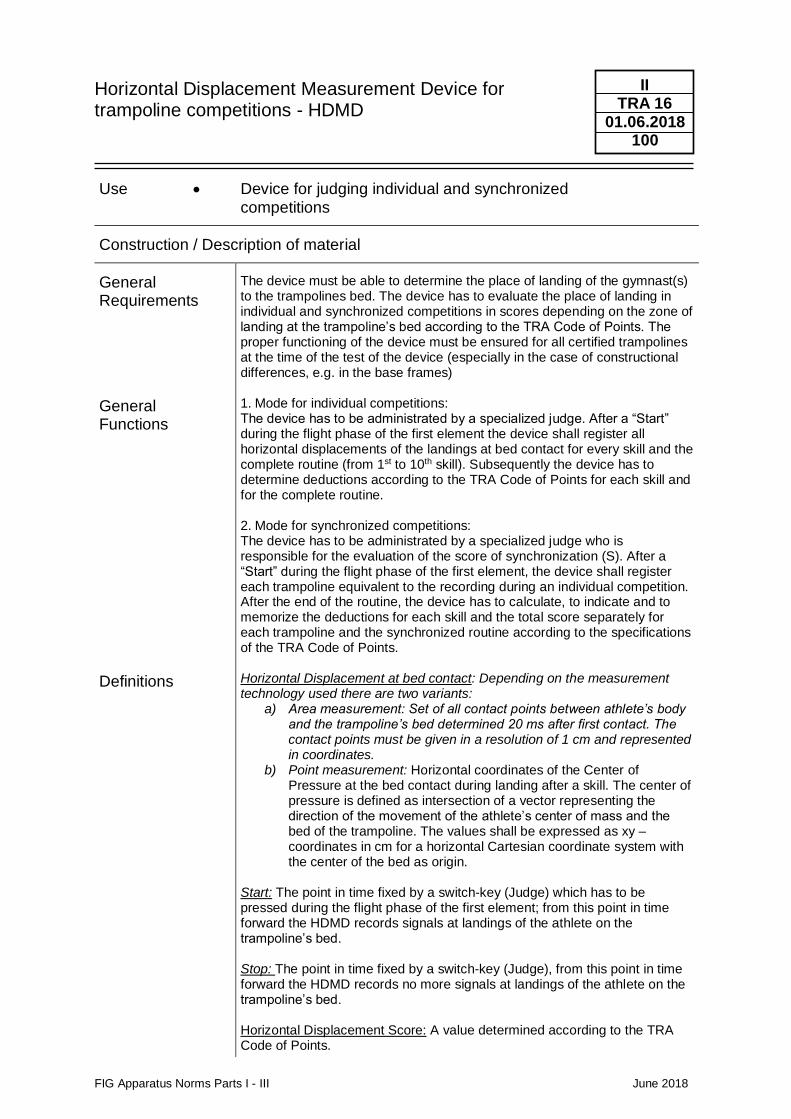
Horizontal Displacement Measurement Device for trampoline competitions - HDMD
FIG Apparatus Norms Parts I - III June 2018
II TRA 16
01.06.2018 100
Use • Device for judging individual and synchronized competitions
Construction / Description of material
General Requirements
General Functions Definitions
The device must be able to determine the place of landing of the gymnast(s) to the trampolines bed. The device has to evaluate the place of landing in individual and synchronized competitions in scores depending on the zone of landing at the trampoline’s bed according to the TRA Code of Points. The proper functioning of the device must be ensured for all certified trampolines at the time of the test of the device (especially in the case of constructional differences, e.g. in the base frames) 1. Mode for individual competitions: The device has to be administrated by a specialized judge. After a “Start” during the flight phase of the first element the device shall register all horizontal displacements of the landings at bed contact for every skill and the complete routine (from 1st to 10th skill). Subsequently the device has to determine deductions according to the TRA Code of Points for each skill and for the complete routine. 2. Mode for synchronized competitions: The device has to be administrated by a specialized judge who is responsible for the evaluation of the score of synchronization (S). After a “Start” during the flight phase of the first element, the device shall register each trampoline equivalent to the recording during an individual competition. After the end of the routine, the device has to calculate, to indicate and to memorize the deductions for each skill and the total score separately for each trampoline and the synchronized routine according to the specifications of the TRA Code of Points. Horizontal Displacement at bed contact: Depending on the measurement technology used there are two variants:
a) Area measurement: Set of all contact points between athlete’s body and the trampoline’s bed determined 20 ms after first contact. The contact points must be given in a resolution of 1 cm and represented in coordinates.
b) Point measurement: Horizontal coordinates of the Center of Pressure at the bed contact during landing after a skill. The center of pressure is defined as intersection of a vector representing the direction of the movement of the athlete’s center of mass and the bed of the trampoline. The values shall be expressed as xy – coordinates in cm for a horizontal Cartesian coordinate system with the center of the bed as origin.
Start: The point in time fixed by a switch-key (Judge) which has to be pressed during the flight phase of the first element; from this point in time forward the HDMD records signals at landings of the athlete on the trampoline’s bed. Stop: The point in time fixed by a switch-key (Judge), from this point in time forward the HDMD records no more signals at landings of the athlete on the trampoline’s bed. Horizontal Displacement Score: A value determined according to the TRA Code of Points.
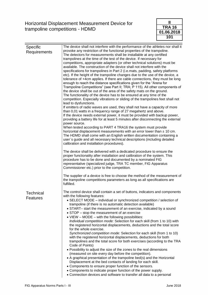
Horizontal Displacement Measurement Device for trampoline competitions - HDMD
FIG Apparatus Norms Parts I - III June 2018
II TRA 16
01.06.2018 101
Specific Requirements
Technical Features
The device shall not interfere with the performance of the athletes nor shall it provoke any restriction of the functional properties of the trampoline. The detectors for measurements shall be installable at any certified trampolines at the time of the test of the device. If necessary for competitions, appropriate adapters (or other technical solutions) must be available. The construction of the device shall not interfere with the specifications for trampolines in Part 2 (i.e.mats, padding, safety platforms etc). If the height of the trampoline changes due to the use of the device, a tolerance of +4cm applies. If there are cable connections, they must be long enough to reach the distance specifications given for the “Arena for Trampoline Competitions” (see Part II; TRA; P 115). All other components of the device shall be out of the area of the safety mats on the ground. The functionality of the device has to be ensured at any time of the competition. Especially vibrations or sliding of the trampolines feet shall not lead to dysfunctions. If emitters of radio waves are used, they shall not have a capacity of more than 0,01 watts in a frequency range of 27 megahertz and above. If the device needs external power, it must be provided with backup power, providing a battery life for at least 5 minutes after disconnecting the external power source. When tested according to PART 4 TRA16 the system must provide horizontal displacement measurements with an error lower than ± 10 cm. The HDMD shall come with an English written documentation containing a user´s guide and all necessary technical descriptions (including detailed calibration and installation procedures). The device shall be delivered with a dedicated procedure to ensure the proper functionality after installation and calibration of the system. This procedure has to be done and documented by a nominated FIG representative (specialized judge, TRA TC member, FIG Apparatus Commissioner etc.) prior to the competition. The supplier of a device is free to choose the method of the measurement of the trampoline competitions parameters as long as all specifications are fulfilled. The control device shall contain a set of buttons, indicators and components with the following features:
• SELECT MODE – individual or synchronized competition / selection of trampoline (if there is no automatic detection available)
• START– start the measurement of an exercise, indicated by a sound
• STOP – stop the measurement of an exercise
• VIEW – MODE – with the following possibilities: Individual competition mode: Selection for each skill (from 1 to 10) with the registered horizontal displacements, deductions and the total score for the whole exercise. Synchronized competition mode: Selection for each skill (from 1 to 10) with the registered horizontal displacements, deductions for both trampolines and the total score for both exercises (according to the TRA Code of Points)
• Possibility to adjust the size of the zones to the real dimensions (measured on site every day before the competition).
• A graphical presentation of the trampoline bed(s) and the Horizontal Displacement at the bed contacts of landing for each skill.
• Components to ensure proper function of the sensors.
• Components to indicate proper function of the power supply.
• Connection devices and software to transfer all data to a personal
Horizontal Displacement Measurement Device for trampoline competitions - HDMD
FIG Apparatus Norms Parts I - III June 2018
II TRA 16
01.06.2018 102
Procedures for Approval
computer. The data shall be available in a standard data format (i.e.csv, pdf, etc.).
• Software to memorize and print all data on a personal computer for each skill and the complete exercises.
If specific reference points or lines at the sensors are essential for the calibration process, they shall be indicated unmistakably at the devices. The approval of a HDMD shall meet the following requirements:
• Confirmation by a member federation of the FIG (according to FIG Apparatus Norms Part III, clause 4).
• Presentation at a testing institute (forwarding a full technical documentation written in English and the complete equipment, if necessary with a special adapter according to: FIG Apparatus Part IV, TRA16 - HDMD
• Confirmation by a TC member ordered by FIG-TC-TRA-President about the functional status during a FIG competition. This confirmation must include in particular the check of all calculation steps required by the TRA Code of Points.
With successful fulfilment of all procedures the certification shall be given by the General Secretary.

FIG Apparatus Norms Parts I - III June 2018
II ACRO
01.01.2006 103
2.5 ACRO Acrobatic Gymnastics
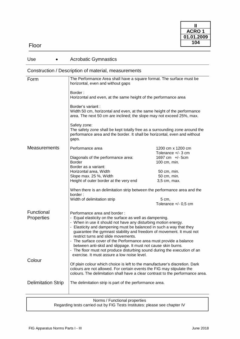
Floor
FIG Apparatus Norms Parts I - III June 2018
II ACRO 1
01.01.2009 104
Use • Acrobatic Gymnastics
Construction / Description of material, measurements
Form
Measurements
Functional Properties
Colour Delimitation Strip
The Performance Area shall have a square format. The surface must be horizontal, even and without gaps Border : Horizontal and even, at the same height of the performance area Border‘s variant : Width 50 cm, horizontal and even, at the same height of the performance area. The next 50 cm are inclined; the slope may not exceed 25%, max. Safety zone: The safety zone shall be kept totally free as a surrounding zone around the performance area and the border. It shall be horizontal, even and without gaps. Performance area 1200 cm x 1200 cm Tolerance +/- 3 cm Diagonals of the performance area: 1697 cm +/- 5cm Border 100 cm, min. Border as a variant: Horizontal area, Width 50 cm, min. Slope max. 25 %, Width 50 cm, min. Height of outer border at the very end 3,5 cm, max. When there is an delimitation strip between the performance area and the border : Width of delimitation strip 5 cm, Tolerance +/- 0,5 cm Performance area and border : - Equal elasticity on the surface as well as dampening. - When in use it should not have any disturbing motion energy. - Elasticity and dampening must be balanced in such a way that they guarantee the gymnast stability and freedom of movement. It must not restrict turns and slide movements. - The surface cover of the Performance area must provide a balance between anti-skid and slippage. It must not cause skin burns. - The floor must not produce disturbing sound during the execution of an exercise. It must assure a low noise level. Of plain colour which choice is left to the manufacturer‘s discretion. Dark colours are not allowed. For certain events the FIG may stipulate the colours. The delimitation shall have a clear contrast to the performance area. The delimitation strip is part of the performance area.
Norms / Functional properties Regarding tests carried out by FIG Tests Institutes: please see chapter IV
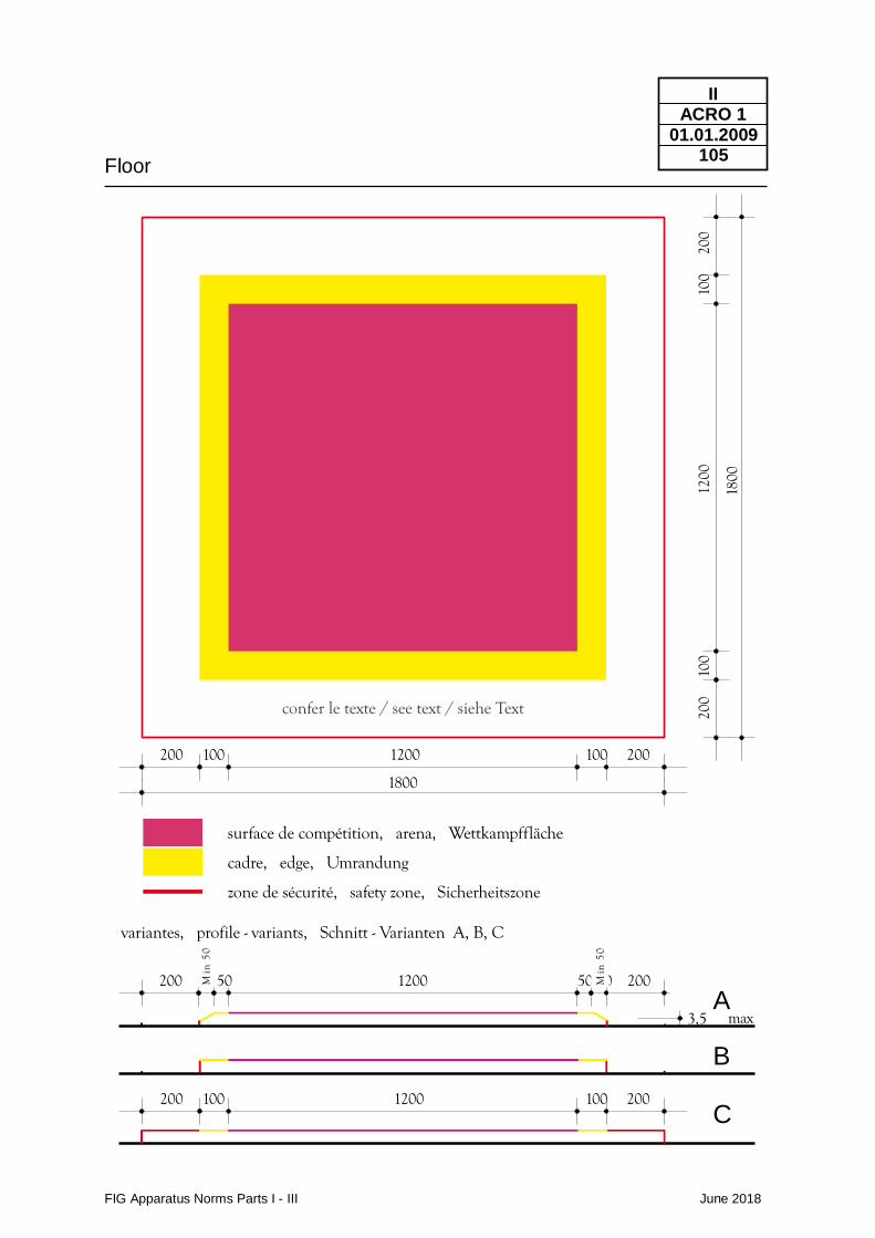
Floor
FIG Apparatus Norms Parts I - III June 2018
II ACRO 1
01.01.2009 105
200 100 1200 100 200
1800
surface de compétition, arena, Wettkampffläche
cadre, edge, Umrandung
zone de sécurité, safety zone, Sicherheitszone
200
100
1200
100
200
1800
confer le texte / see text / siehe Text
200 100 1200 100 200
200 50 50 1200 50 50 200
variantes, profile - variants, Schnitt - Varianten A, B, C
3,5 max
Min
50
Min
50
A
B
C
Landing Mat
FIG Apparatus Norms Parts I - III June 2018
II ACRO 11
01.01.2009 106
Use • Acrobatic Gymnastics
Construction / Description of material, measurements
Use Form and functional properties
Measurements
For landing a mat shall be available. The use is not compulsory. The functional properties of the landing mat must be identical to those of the landing mats MAG 11 and WAG 11. The minimum size of the landing mat is 200 cm x 150 cm x 20 cm
FIG Apparatus Norms Parts I - III June 2018
II AER
01.01.2009 107
2.6 AER Aerobic Gymnastics
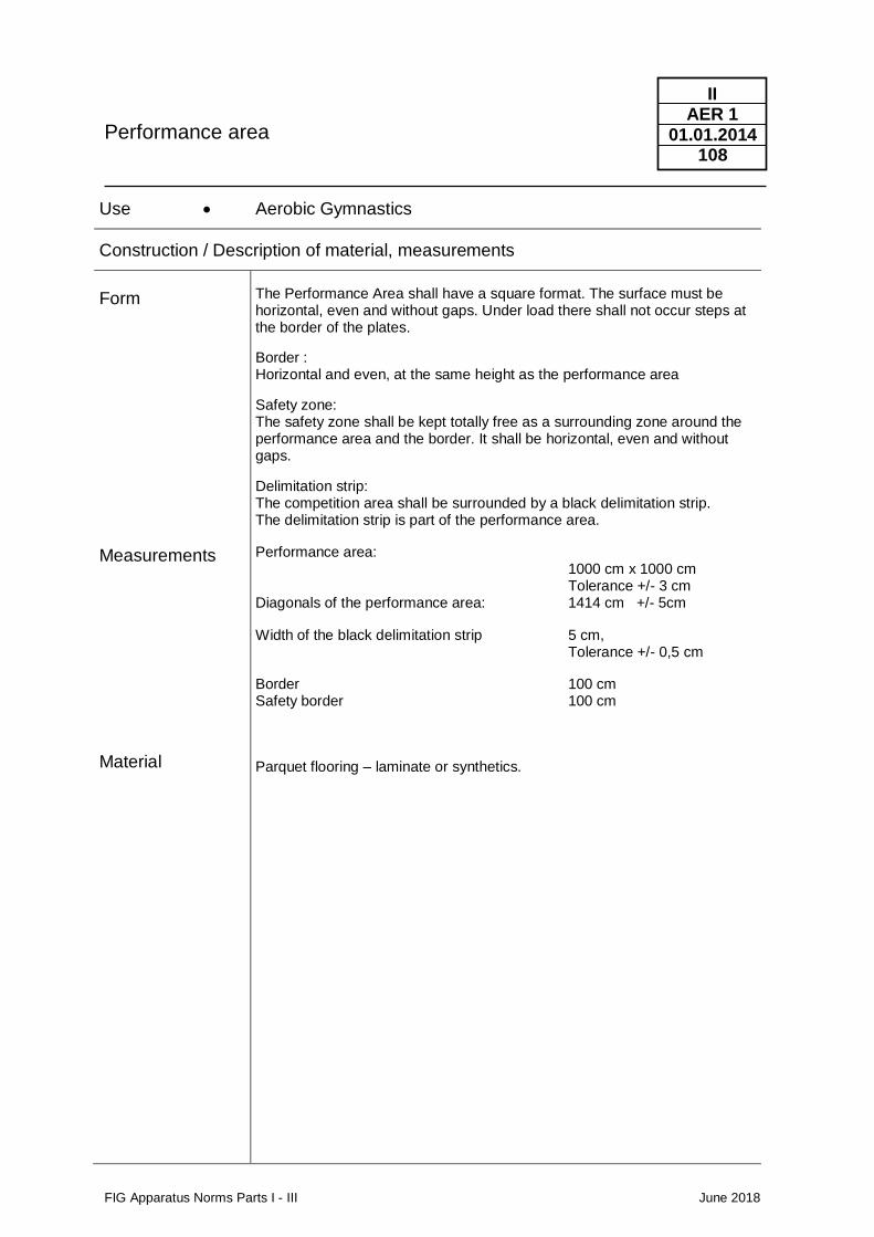
Performance area
FIG Apparatus Norms Parts I - III June 2018
II AER 1
01.01.2014 108
Use • Aerobic Gymnastics
Construction / Description of material, measurements
Form
Measurements
Material
The Performance Area shall have a square format. The surface must be horizontal, even and without gaps. Under load there shall not occur steps at the border of the plates.
Border : Horizontal and even, at the same height as the performance area
Safety zone: The safety zone shall be kept totally free as a surrounding zone around the performance area and the border. It shall be horizontal, even and without gaps.
Delimitation strip: The competition area shall be surrounded by a black delimitation strip. The delimitation strip is part of the performance area.
Performance area: 1000 cm x 1000 cm Tolerance +/- 3 cm Diagonals of the performance area: 1414 cm +/- 5cm
Width of the black delimitation strip 5 cm, Tolerance +/- 0,5 cm
Border 100 cm Safety border 100 cm
Parquet flooring – laminate or synthetics.
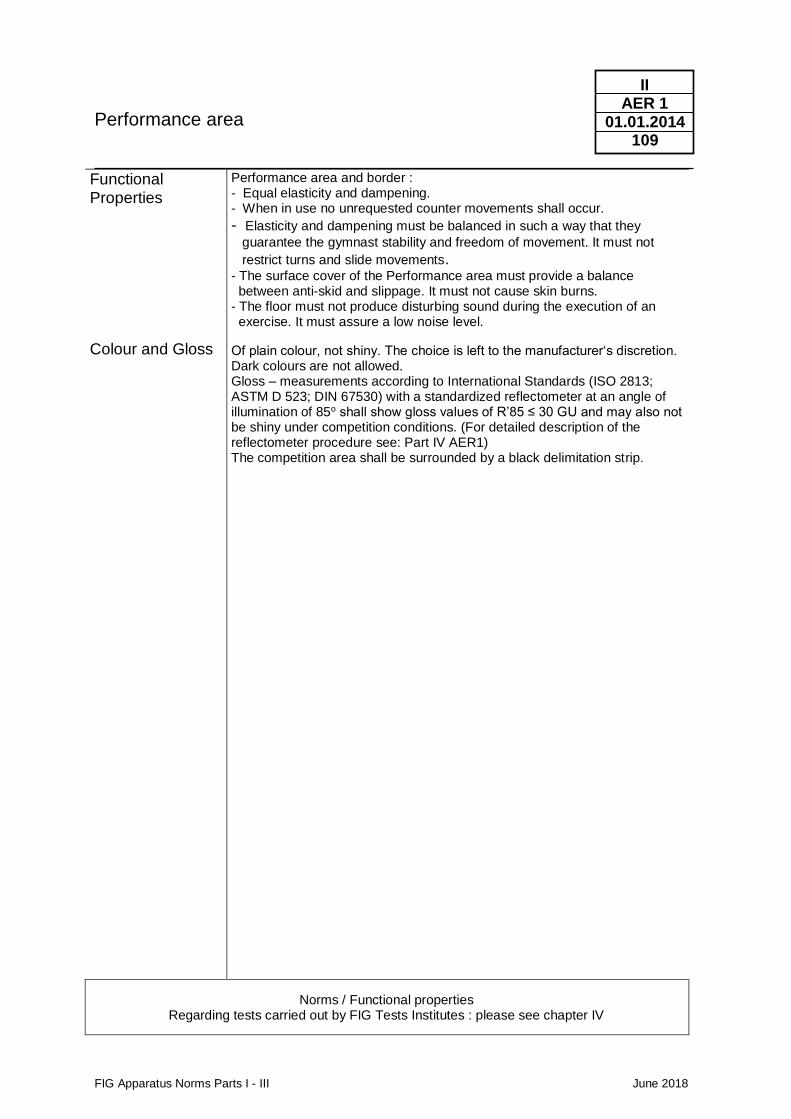
Performance area
FIG Apparatus Norms Parts I - III June 2018
II AER 1
01.01.2014 109
Functional Properties
Colour and Gloss
Performance area and border : - Equal elasticity and dampening. - When in use no unrequested counter movements shall occur.
- Elasticity and dampening must be balanced in such a way that they
guarantee the gymnast stability and freedom of movement. It must not
restrict turns and slide movements. - The surface cover of the Performance area must provide a balance between anti-skid and slippage. It must not cause skin burns. - The floor must not produce disturbing sound during the execution of an exercise. It must assure a low noise level.
Of plain colour, not shiny. The choice is left to the manufacturer‘s discretion. Dark colours are not allowed. Gloss – measurements according to International Standards (ISO 2813; ASTM D 523; DIN 67530) with a standardized reflectometer at an angle of illumination of 85o shall show gloss values of R’85 ≤ 30 GU and may also not be shiny under competition conditions. (For detailed description of the reflectometer procedure see: Part IV AER1) The competition area shall be surrounded by a black delimitation strip.
Norms / Functional properties Regarding tests carried out by FIG Tests Institutes : please see chapter IV
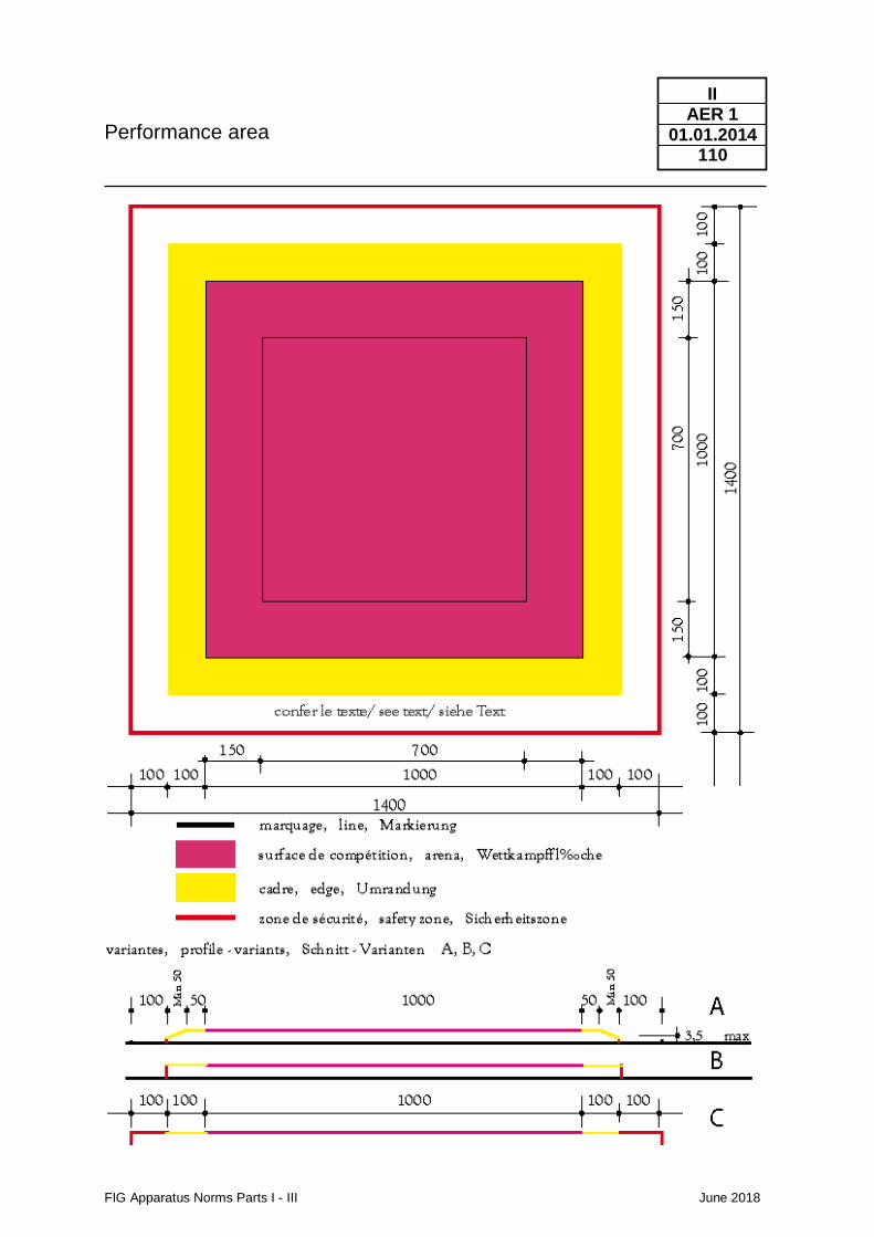
Performance area
FIG Apparatus Norms Parts I - III June 2018
II AER 1
01.01.2014 110
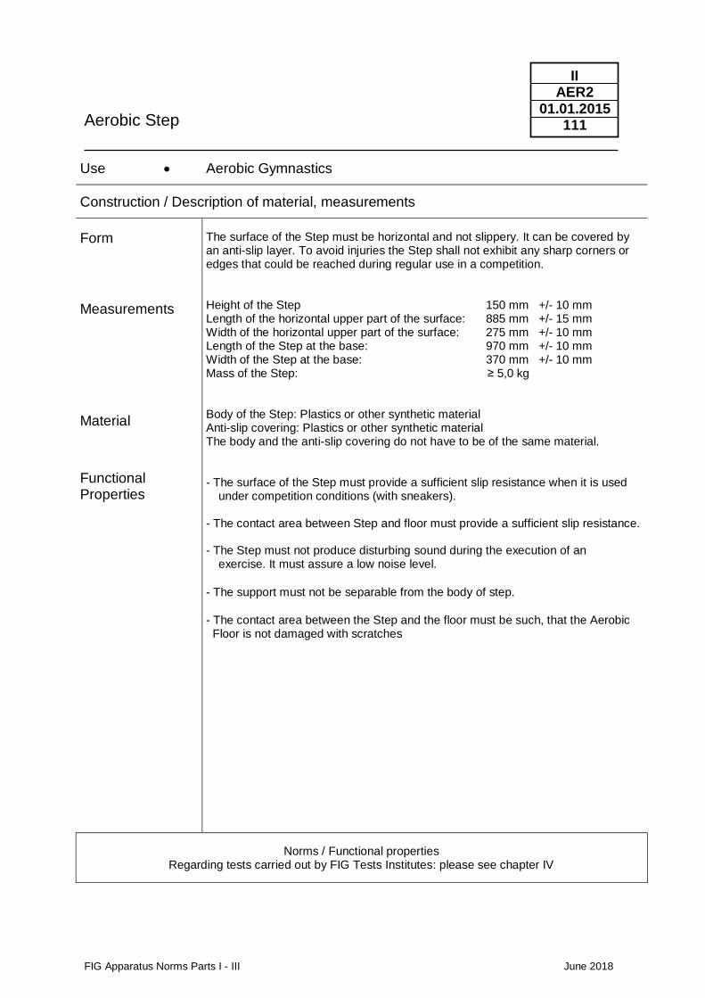
Aerobic Step
FIG Apparatus Norms Parts I - III June 2018
II AER2
01.01.2015 111
Use • Aerobic Gymnastics
Construction / Description of material, measurements
Form
Measurements
Material
Functional Properties
The surface of the Step must be horizontal and not slippery. It can be covered by an anti-slip layer. To avoid injuries the Step shall not exhibit any sharp corners or edges that could be reached during regular use in a competition. Height of the Step 150 mm +/- 10 mm Length of the horizontal upper part of the surface: 885 mm +/- 15 mm Width of the horizontal upper part of the surface: 275 mm +/- 10 mm Length of the Step at the base: 970 mm +/- 10 mm Width of the Step at the base: 370 mm +/- 10 mm Mass of the Step: ≥ 5,0 kg Body of the Step: Plastics or other synthetic material Anti-slip covering: Plastics or other synthetic material The body and the anti-slip covering do not have to be of the same material. - The surface of the Step must provide a sufficient slip resistance when it is used
under competition conditions (with sneakers). - The contact area between Step and floor must provide a sufficient slip resistance. - The Step must not produce disturbing sound during the execution of an
exercise. It must assure a low noise level.
- The support must not be separable from the body of step. - The contact area between the Step and the floor must be such, that the Aerobic Floor is not damaged with scratches
Norms / Functional properties Regarding tests carried out by FIG Tests Institutes: please see chapter IV
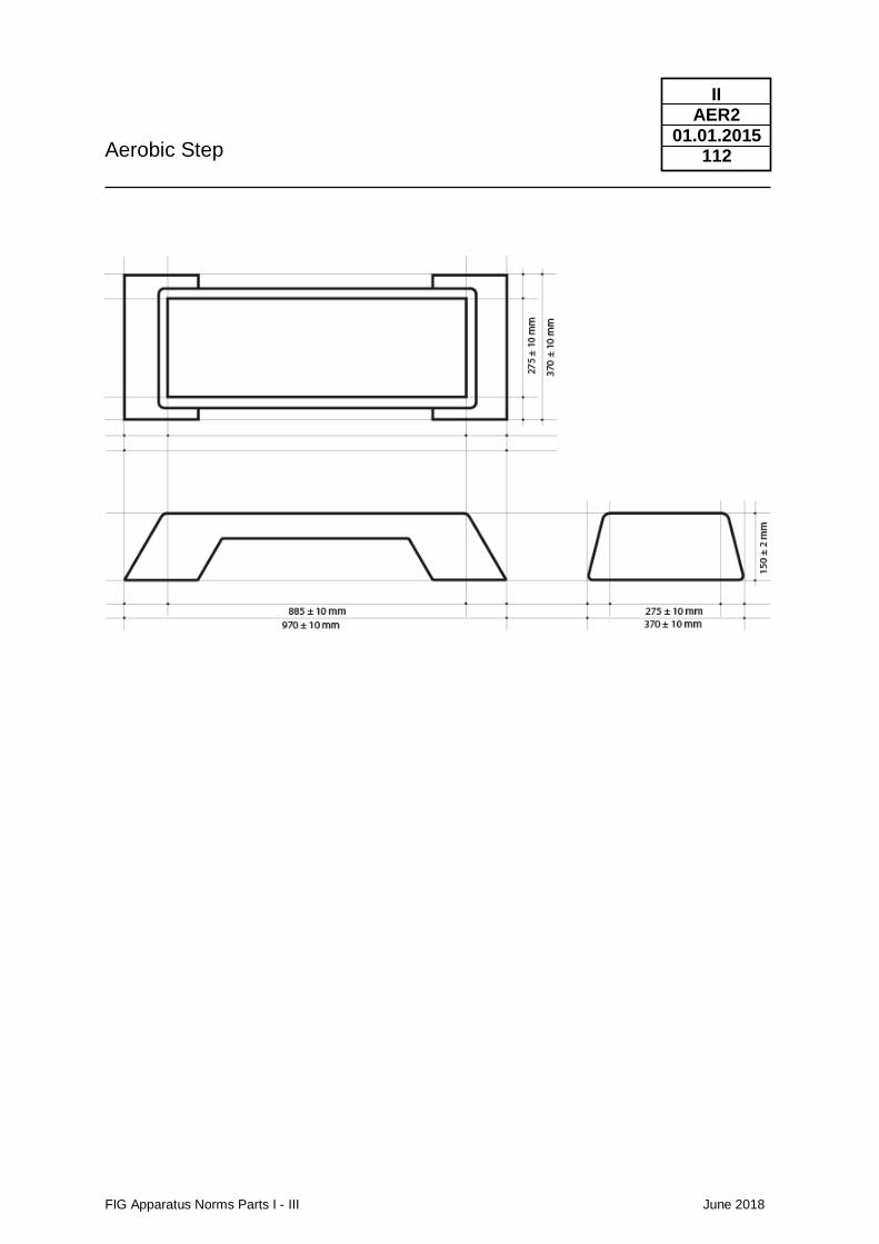
Aerobic Step
FIG Apparatus Norms Parts I - III June 2018
II AER2
01.01.2015 112
FIG Apparatus Norms Parts I - III June 2018
II
01.01.2009 113
3. Surfaces of apparatus, safety zones, total surfaces
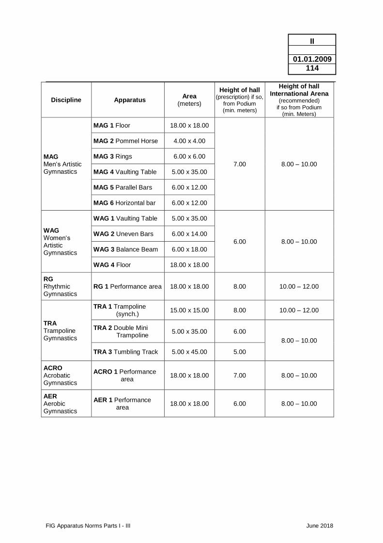
FIG Apparatus Norms Parts I - III June 2018
II
01.01.2009 114
Discipline Apparatus Area
(meters)
Height of hall (prescription) if so,
from Podium (min. meters)
Height of hall International Arena
(recommended) if so from Podium
(min. Meters)
MAG Men‘s Artistic Gymnastics
MAG 1 Floor 18.00 x 18.00
7.00 8.00 – 10.00
MAG 2 Pommel Horse 4.00 x 4.00
MAG 3 Rings 6.00 x 6.00
MAG 4 Vaulting Table 5.00 x 35.00
MAG 5 Parallel Bars 6.00 x 12.00
MAG 6 Horizontal bar 6.00 x 12.00
WAG Women‘s Artistic Gymnastics
WAG 1 Vaulting Table 5.00 x 35.00
6.00 8.00 – 10.00
WAG 2 Uneven Bars 6.00 x 14.00
WAG 3 Balance Beam 6.00 x 18.00
WAG 4 Floor 18.00 x 18.00
RG Rhythmic Gymnastics
RG 1 Performance area 18.00 x 18.00 8.00 10.00 – 12.00
TRA Trampoline Gymnastics
TRA 1 Trampoline (synch.)
15.00 x 15.00 8.00 10.00 – 12.00
TRA 2 Double Mini Trampoline
5.00 x 35.00 6.00
8.00 – 10.00
TRA 3 Tumbling Track 5.00 x 45.00 5.00
ACRO Acrobatic Gymnastics
ACRO 1 Performance area
18.00 x 18.00 7.00 8.00 – 10.00
AER Aerobic Gymnastics
AER 1 Performance area
18.00 x 18.00 6.00 8.00 – 10.00
FIG Apparatus Norms Parts I - III June 2018
II
01.01.2009 115
4. Competition area Recommended Standards. For FIG Events the Placement of the Apparatuses and Podiums has to be approved by the FIG.
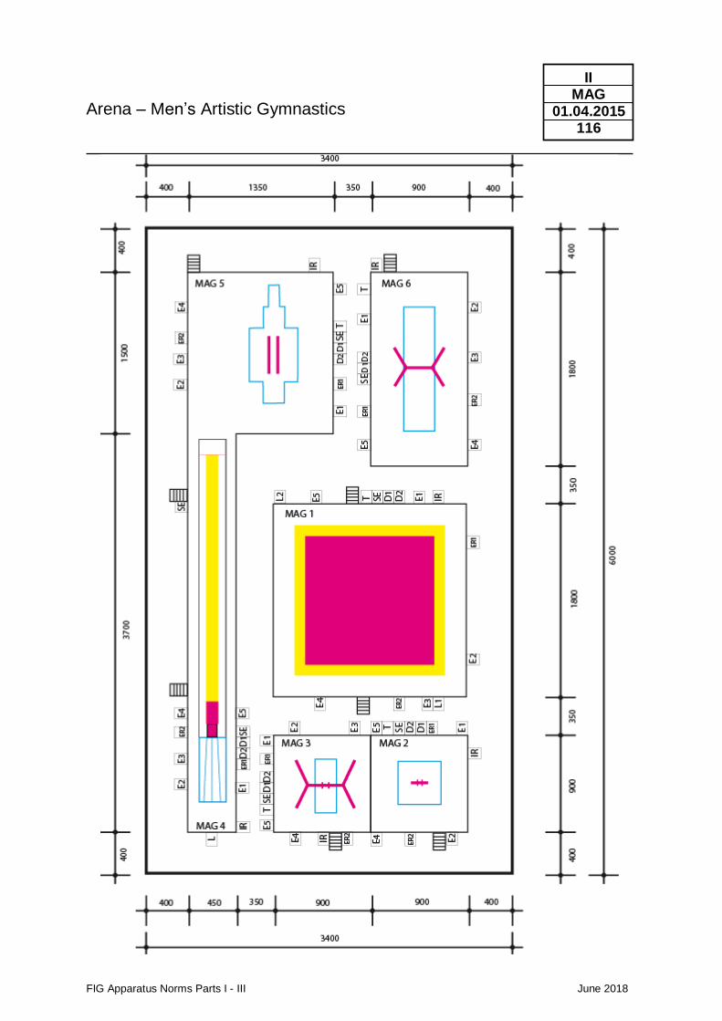
Arena – Men’s Artistic Gymnastics
FIG Apparatus Norms Parts I - III June 2018
II MAG
01.04.2015 116
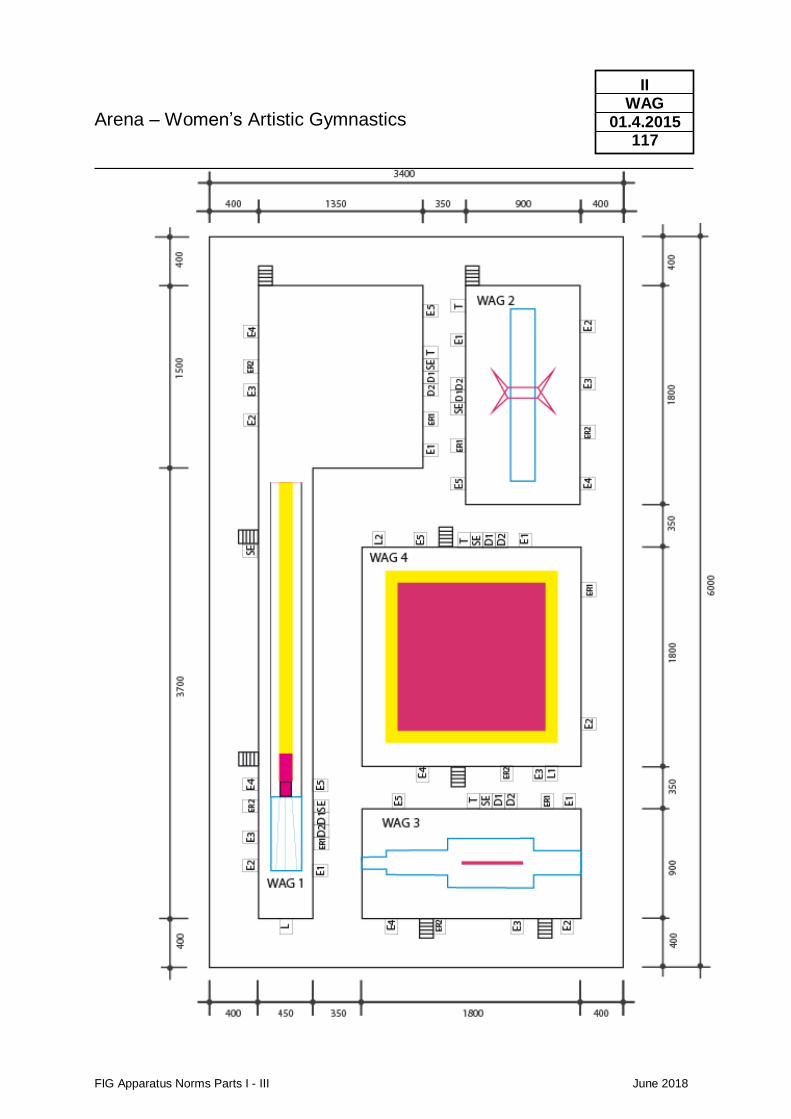
Arena – Women’s Artistic Gymnastics
FIG Apparatus Norms Parts I - III June 2018
II WAG
01.4.2015 117
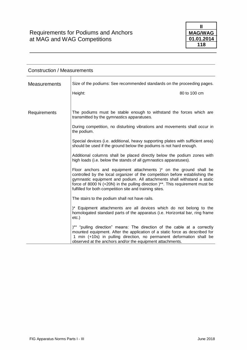
Requirements for Podiums and Anchors at MAG and WAG Competitions
FIG Apparatus Norms Parts I - III June 2018
II
MAG/WAG 01.01.2014
118
Construction / Measurements
Measurements Requirements
Size of the podiums: See recommended standards on the proceeding pages. Height: 80 to 100 cm The podiums must be stable enough to withstand the forces which are transmitted by the gymnastics apparatuses. During competition, no disturbing vibrations and movements shall occur in the podium. Special devices (i.e. additional, heavy supporting plates with sufficient area) should be used if the ground below the podiums is not hard enough. Additional columns shall be placed directly below the podium zones with high loads (i.e. below the stands of all gymnastics apparatuses). Floor anchors and equipment attachments )* on the ground shall be controlled by the local organizer of the competition before establishing the gymnastic equipment and podium. All attachments shall withstand a static force of 8000 N (+20N) in the pulling direction )**. This requirement must be fulfilled for both competition site and training sites. The stairs to the podium shall not have rails. )* Equipment attachments are all devices which do not belong to the homologated standard parts of the apparatus (i.e. Horizontal bar, ring frame etc.) )** “pulling direction” means: The direction of the cable at a correctly mounted equipment. After the application of a static force as described for 1 min (+10s) in pulling direction, no permanent deformation shall be observed at the anchors and/or the equipment attachments.
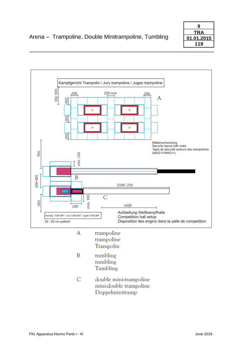
Arena – Trampoline, Double Minitrampoline, Tumbling
FIG Apparatus Norms Parts I - III June 2018
II
TRA 01.01.2015
119

FIG Apparatus Norms Parts I - III June 2018
II
TRA 01.01.2011
121
5. Apparatus Control Forms
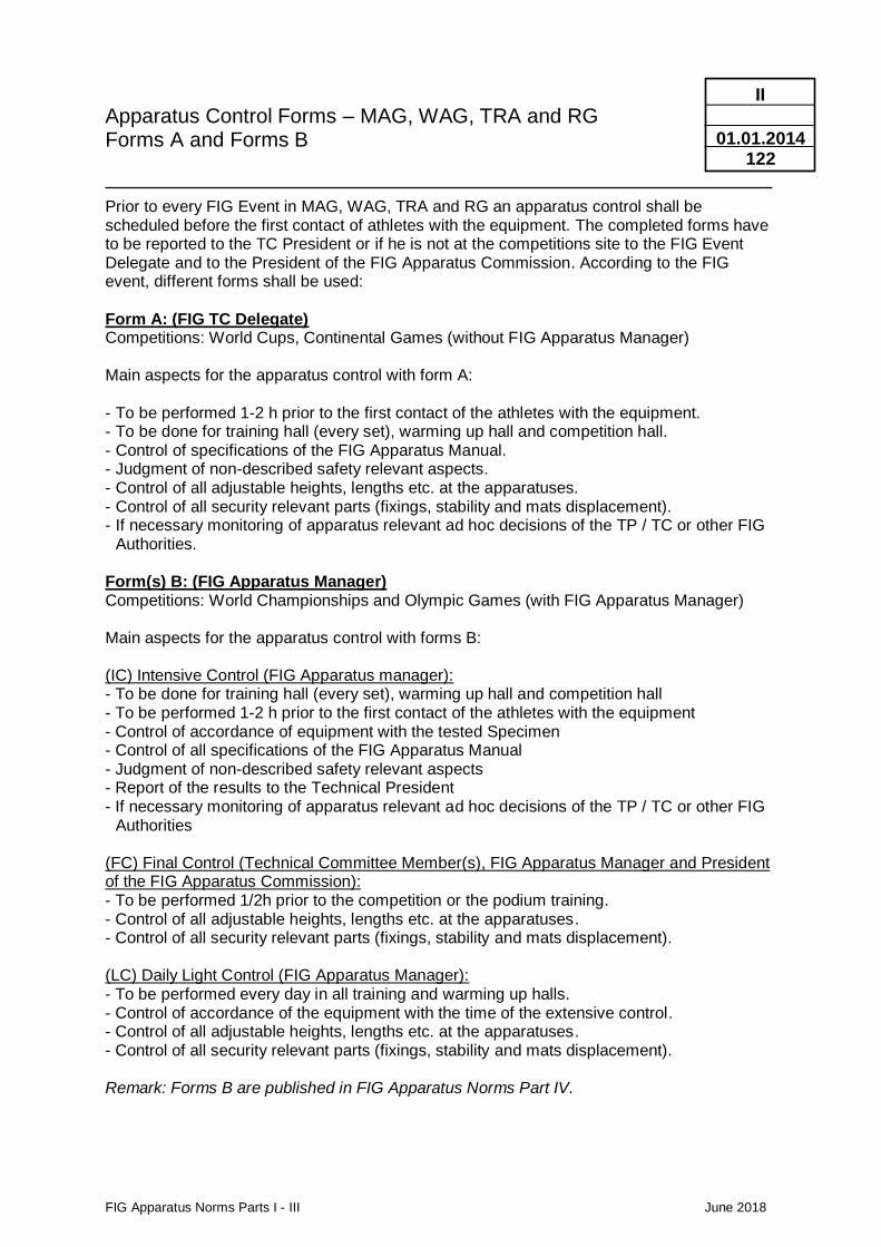
Apparatus Control Forms – MAG, WAG, TRA and RG Forms A and Forms B
FIG Apparatus Norms Parts I - III June 2018
II
01.01.2014
122
Prior to every FIG Event in MAG, WAG, TRA and RG an apparatus control shall be scheduled before the first contact of athletes with the equipment. The completed forms have to be reported to the TC President or if he is not at the competitions site to the FIG Event Delegate and to the President of the FIG Apparatus Commission. According to the FIG event, different forms shall be used: Form A: (FIG TC Delegate) Competitions: World Cups, Continental Games (without FIG Apparatus Manager) Main aspects for the apparatus control with form A: - To be performed 1-2 h prior to the first contact of the athletes with the equipment. - To be done for training hall (every set), warming up hall and competition hall. - Control of specifications of the FIG Apparatus Manual. - Judgment of non-described safety relevant aspects. - Control of all adjustable heights, lengths etc. at the apparatuses. - Control of all security relevant parts (fixings, stability and mats displacement). - If necessary monitoring of apparatus relevant ad hoc decisions of the TP / TC or other FIG
Authorities. Form(s) B: (FIG Apparatus Manager) Competitions: World Championships and Olympic Games (with FIG Apparatus Manager) Main aspects for the apparatus control with forms B: (IC) Intensive Control (FIG Apparatus manager): - To be done for training hall (every set), warming up hall and competition hall - To be performed 1-2 h prior to the first contact of the athletes with the equipment - Control of accordance of equipment with the tested Specimen - Control of all specifications of the FIG Apparatus Manual - Judgment of non-described safety relevant aspects - Report of the results to the Technical President - If necessary monitoring of apparatus relevant ad hoc decisions of the TP / TC or other FIG
Authorities (FC) Final Control (Technical Committee Member(s), FIG Apparatus Manager and President of the FIG Apparatus Commission): - To be performed 1/2h prior to the competition or the podium training. - Control of all adjustable heights, lengths etc. at the apparatuses. - Control of all security relevant parts (fixings, stability and mats displacement). (LC) Daily Light Control (FIG Apparatus Manager): - To be performed every day in all training and warming up halls. - Control of accordance of the equipment with the time of the extensive control. - Control of all adjustable heights, lengths etc. at the apparatuses. - Control of all security relevant parts (fixings, stability and mats displacement). Remark: Forms B are published in FIG Apparatus Norms Part IV.
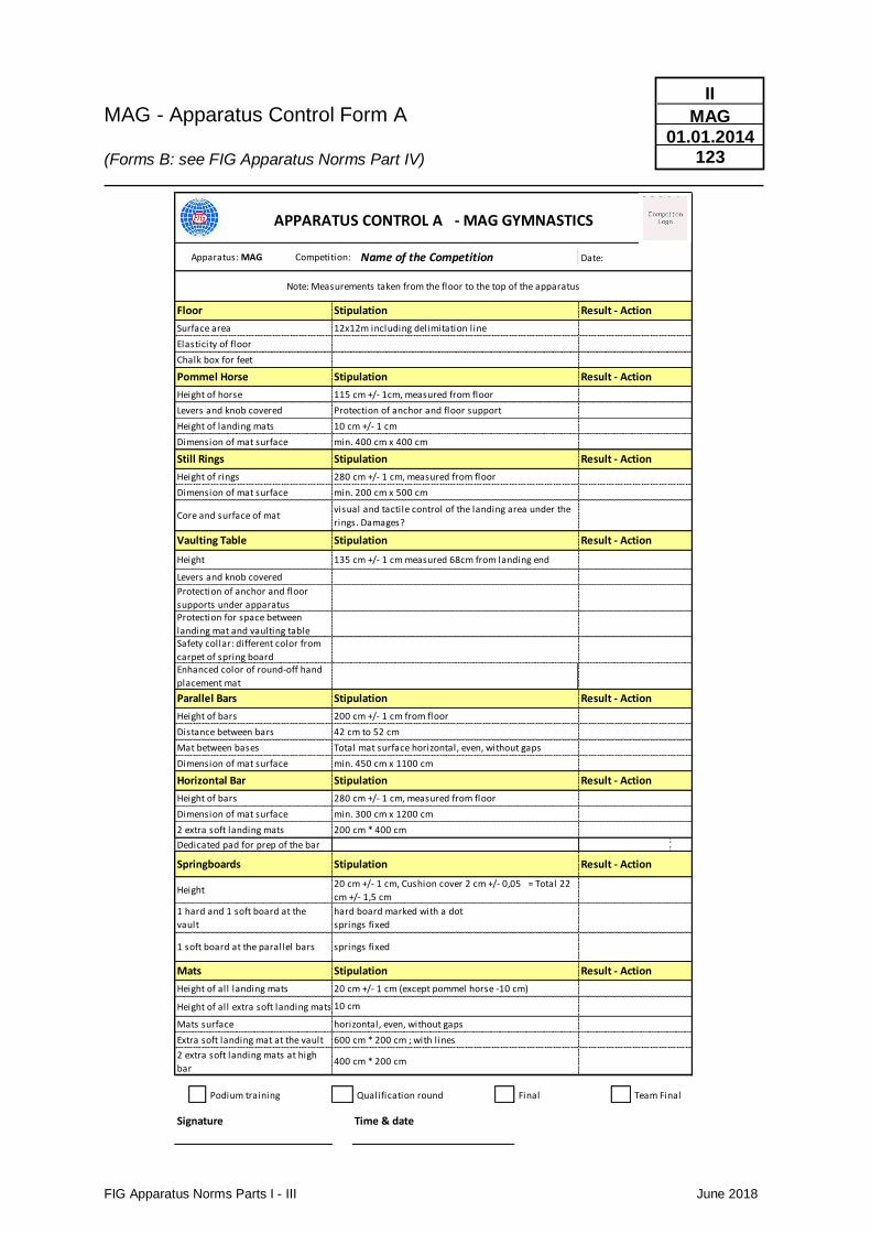
MAG - Apparatus Control Form A (Forms B: see FIG Apparatus Norms Part IV)
FIG Apparatus Norms Parts I - III June 2018
II
MAG 01.01.2014
123
Apparatus: MAG
2 extra soft landing mats 200 cm * 400 cm
Dedicated pad for prep of the bar
Height of all extra soft landing mats
Podium training Qualification round Final Team Final
Signature Time & date
APPARATUS CONTROL A - MAG GYMNASTICS
Competition: Date:
Note: Measurements taken from the floor to the top of the apparatus
Floor Stipulation Result - Action
Surface area 12x12m including delimitation line
Name of the Competition
1 hard and 1 soft board at the
vault
hard board marked with a dot
springs fixed
Elasticity of floor
Chalk box for feet
Vaulting Table Stipulation Result - Action
Height 135 cm +/- 1 cm measured 68cm from landing end
Levers and knob covered
Protection of anchor and floor
supports under apparatusProtection for space between
landing mat and vaulting table
Mat between bases Total mat surface horizontal, even, without gaps
Springboards Stipulation Result - Action
Height20 cm +/- 1 cm, Cushion cover 2 cm +/- 0,05 = Total 22
cm +/- 1,5 cm
Dimension of mat surface min. 450 cm x 1100 cm
Dimension of mat surface min. 300 cm x 1200 cm
1 soft board at the parallel bars springs fixed
Pommel Horse Stipulation Result - Action
Height of horse 115 cm +/- 1cm, measured from floor
Levers and knob covered Protection of anchor and floor support
Height of bars 200 cm +/- 1 cm from floor
Core and surface of matvisual and tactile control of the landing area under the
rings. Damages?
Distance between bars 42 cm to 52 cm
Safety collar: different color from
carpet of spring board
Height of rings 280 cm +/- 1 cm, measured from floor
Dimension of mat surface min. 200 cm x 500 cm
Parallel Bars Stipulation Result - Action
Enhanced color of round-off hand
placement mat
Height of landing mats 10 cm +/- 1 cm
Dimension of mat surface min. 400 cm x 400 cm
Still Rings Stipulation Result - Action
Horizontal Bar Stipulation Result - Action
Height of bars 280 cm +/- 1 cm, measured from floor
Extra soft landing mat at the vault 600 cm * 200 cm ; with l ines
2 extra soft landing mats at high
bar400 cm * 200 cm
Mats Stipulation Result - Action
Height of all landing mats 20 cm +/- 1 cm (except pommel horse -10 cm)
10 cm
Mats surface horizontal, even, without gaps
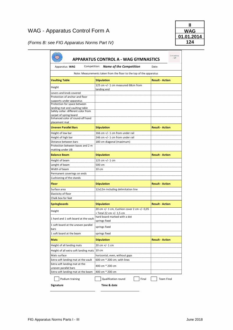
WAG - Apparatus Control Form A (Forms B: see FIG Apparatus Norms Part IV)
FIG Apparatus Norms Parts I - III June 2018
II
WAG 01.01.2014
124
Apparatus: WAG
Height of all extra soft landing mats
Podium training Qualification round Final Team Final
Signature Time & date
Extra soft landing mat at the
uneven parallel bars400 cm * 200 cm
Extra soft landing mat at the beam 400 cm * 200 cm
Mats surface horizontal, even, without gaps
Extra soft landing mat at the vault 600 cm * 200 cm; with lines
Height of all landing mats 20 cm +/- 1 cm
10 cm
1 soft board at the beam springs fixed
Mats Stipulation Result - Action
1 hard and 1 soft board at the vaulthard board marked with a dot
springs fixed
1 soft board at the uneven parallel
barssprings fixed
APPARATUS CONTROL A - WAG GYMNASTICS
Competition: Date:
Note: Measurements taken from the floor to the top of the apparatus
Floor Stipulation Result - Action
Name of the Competition
Surface area 12x12m including delimitation line
Elasticity of floor
Chalk box for feet
Vaulting Table Stipulation Result - Action
Height125 cm +/- 1 cm measured 68cm from
landing endLevers and knob covered
Protection of anchor and floor
supports under apparatusProtection for space between
landing mat and vaulting tableSafety collar: different color from
carpet of spring boardEnhanced color of round-off hand
placement mat
Uneven Parallel Bars Stipulation Result - Action
Height of low bar 166 cm +/- 1 cm from under rail
Height of high bar 246 cm +/- 1 cm from under rail
Distance between bars 180 cm diagonal (maximum)
Protection between bases and 2 m
matting under UB
Balance Beam Stipulation Result - Action
Height of beam 125 cm +/- 1 cm
Lenght of beam 500 cm
Width of beam 10 cm
Permanent coverings on ends
Cushioning of the stands
Springboards Stipulation Result - Action
Height20 cm +/- 1 cm, Cushion cover 2 cm +/- 0,05
= Total 22 cm +/- 1,5 cm
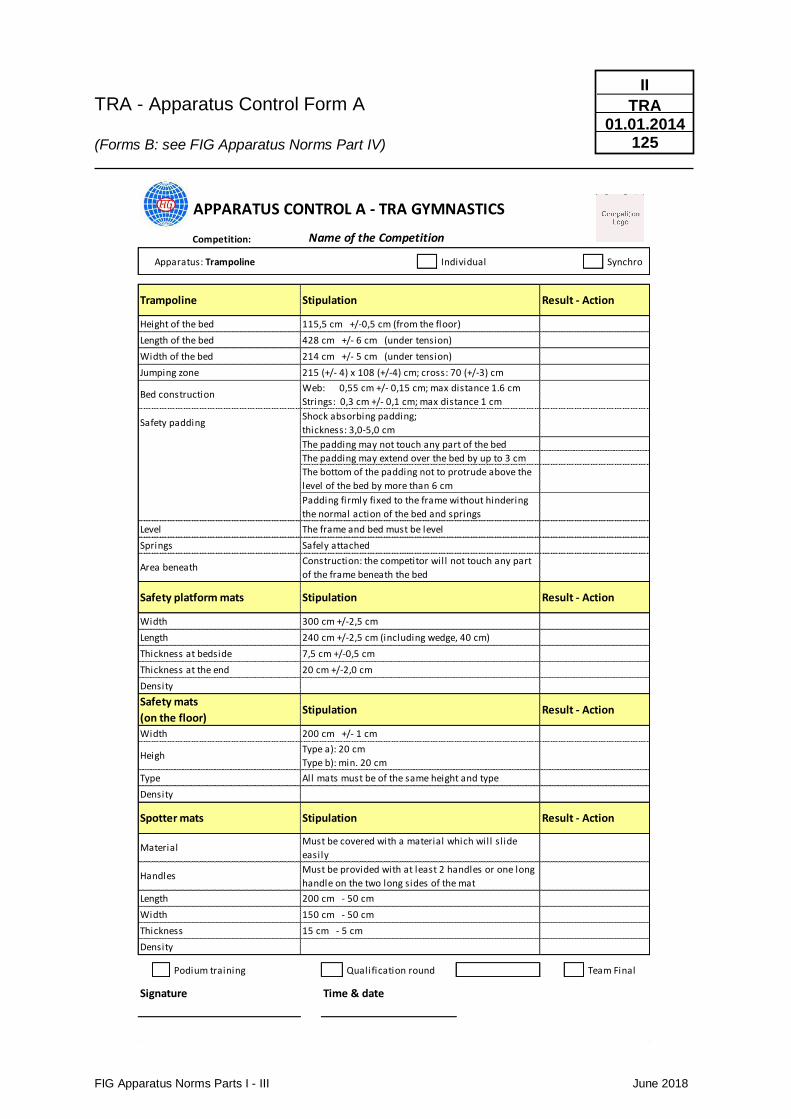
TRA - Apparatus Control Form A (Forms B: see FIG Apparatus Norms Part IV)
FIG Apparatus Norms Parts I - III June 2018
II
TRA 01.01.2014
125
Competition:
Apparatus: Trampoline Individual Synchro
Podium training Qualification round Team Final
Signature Time & date
APPARATUS CONTROL A - TRA GYMNASTICS
Trampoline Stipulation Result - Action
Height of the bed 115,5 cm +/-0,5 cm (from the floor)
Name of the Competition
Length of the bed 428 cm +/- 6 cm (under tension)
Width of the bed 214 cm +/- 5 cm (under tension)
Jumping zone 215 (+/- 4) x 108 (+/-4) cm; cross: 70 (+/-3) cm
Bed constructionWeb: 0,55 cm +/- 0,15 cm; max distance 1.6 cm
Strings: 0,3 cm +/- 0,1 cm; max distance 1 cm
Safety paddingShock absorbing padding;
thickness: 3,0-5,0 cm
The padding may not touch any part of the bed
The padding may extend over the bed by up to 3 cm
The bottom of the padding not to protrude above the
level of the bed by more than 6 cm
Padding firmly fixed to the frame without hindering
the normal action of the bed and springs
Level The frame and bed must be level
Springs Safely attached
Area beneathConstruction: the competitor will not touch any part
of the frame beneath the bed
Safety platform mats Stipulation Result - Action
Width 300 cm +/-2,5 cm
Length 240 cm +/-2,5 cm (including wedge, 40 cm)
Thickness at bedside 7,5 cm +/-0,5 cm
Thickness at the end 20 cm +/-2,0 cm
Density
Safety mats
(on the floor)Stipulation Result - Action
Width 200 cm +/- 1 cm
HeighType a): 20 cm
Type b): min. 20 cm
Type All mats must be of the same height and type
Density
Spotter mats Stipulation Result - Action
MaterialMust be covered with a material which will sl ide
easily
HandlesMust be provided with at least 2 handles or one long
handle on the two long sides of the mat
Length 200 cm - 50 cm
Width 150 cm - 50 cm
Thickness 15 cm - 5 cm
Density
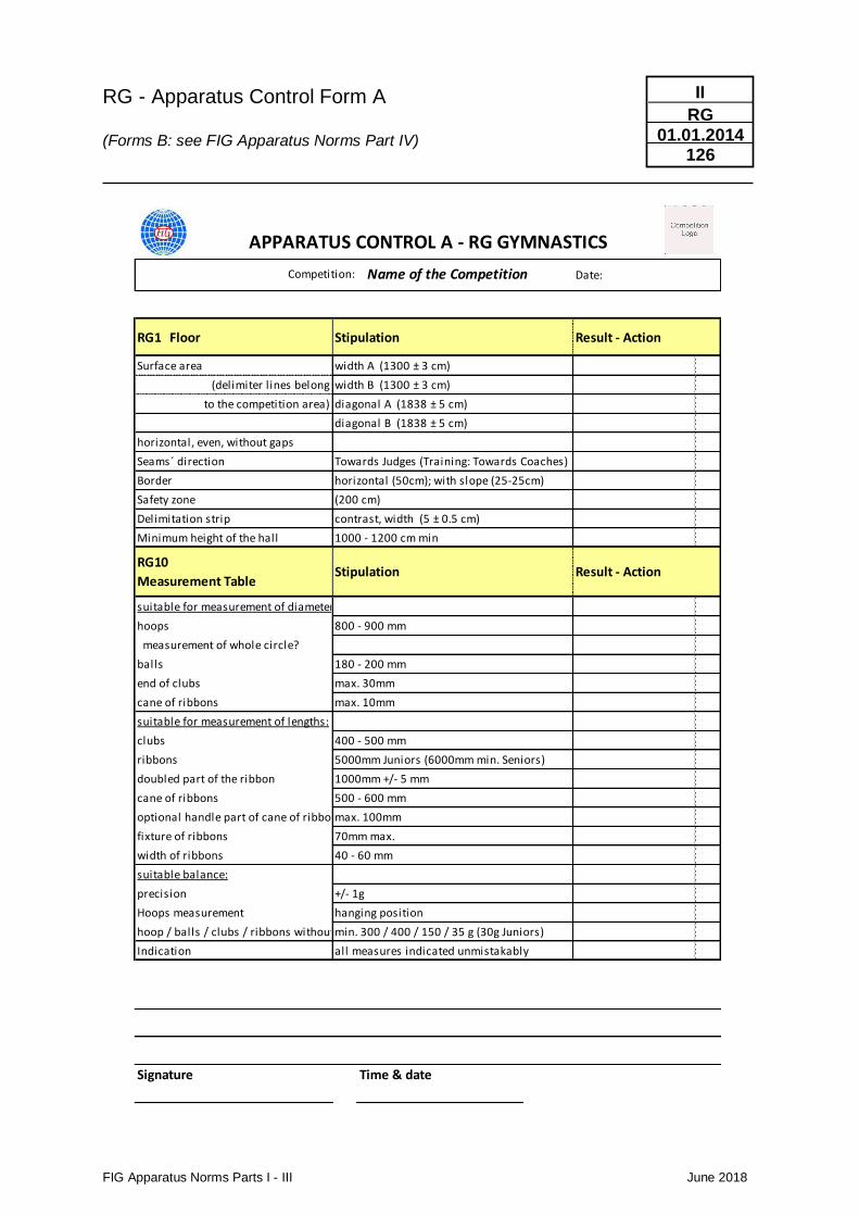
RG - Apparatus Control Form A (Forms B: see FIG Apparatus Norms Part IV)
FIG Apparatus Norms Parts I - III June 2018
II
RG 01.01.2014
126
Apparatus: WAG
Surface area
Delimitation strip
Minimum height of the hall
suitable for measurement of diameters:
hoops
measurement of whole circle?
balls
end of clubs
cane of ribbons
suitable for measurement of lengths:
clubs
ribbons
doubled part of the ribbon
cane of ribbons
optional handle part of cane of ribbons
fixture of ribbons
width of ribbons
suitable balance:
precision
Hoops measurement
hoop / balls / clubs / ribbons without cane
Indication
Signature Time & date
to the competition area) diagonal A (1838 ± 5 cm)
APPARATUS CONTROL A - RG GYMNASTICS
Competition: Date:
RG1 Floor Stipulation Result - Action
width A (1300 ± 3 cm)
(delimiter l ines belong width B (1300 ± 3 cm)
Name of the Competition
diagonal B (1838 ± 5 cm)
horizontal, even, without gaps
Seams´ direction Towards Judges (Training: Towards Coaches)
RG10
Measurement TableStipulation Result - Action
Border horizontal (50cm); with slope (25-25cm)
Safety zone (200 cm)
180 - 200 mm
contrast, width (5 ± 0.5 cm)
1000 - 1200 cm min
800 - 900 mm
max. 30mm
max. 10mm
400 - 500 mm
5000mm Juniors (6000mm min. Seniors)
1000mm +/- 5 mm
500 - 600 mm
max. 100mm
70mm max.
40 - 60 mm
+/- 1g
hanging position
min. 300 / 400 / 150 / 35 g (30g Juniors)
all measures indicated unmistakably
FIG Apparatus Norms Parts I - III June 2018
6. Required Equipment for FIG - Competitions
MAG / WAG / RG / TRA
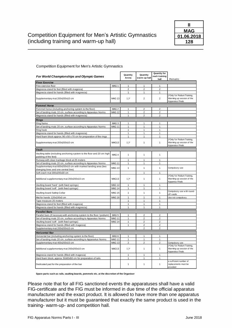
Competition Equipment for Men’s Artistic Gymnastics (including training and warm-up hall)
FIG Apparatus Norms Parts I - III June 2018
II
MAG 01.06.2018
128
Please note that for all FIG sanctioned events the apparatuses shall have a valid FIG-certificate and the FIG must be informed in due time of the official apparatus manufacturer and the exact product. It is allowed to have more than one apparatus manufacturer but it must be guaranteed that exactly the same product is used in the training- warm-up- and competition hall.
Competition Equipment for Men's Artistic Gymnastics
For World Championships and Olympic GamesQuantity
Arena
Quantity
warm-up hall
Quantity for
each training
hall Remarks
Floor Exercise
Free exercise floor MAG 1 1 1 1
Magnesia stand for feet (filled with magesia) 2 2 2
Magnesia stand for hands (filled with magnesia) 1 1 1
Supplementary mat 200x200x10 cm MAG 13 1 )* 2 2
)*Only for Podium Training,
Warming up session of the
Apparatus Finals
Pommel Horse
Pommel horse (including anchoring system to the floor) MAG 2 1 2 2
Set of landing mats 10 cm, surface according to Apparatus Norms MAG 12 1 2 2
Magnesia stand for hands (filled with magnesia) 1 2 2
Rings
Ring frame MAG 3 1 1 1
Set of landing mats 20 cm, surface according to Apparatus Norms MAG 11 1 1 1
Ring hook 1 1 1
Magnesia stand for hands (filled with magnesia) 1 1 1
Hard foam block approx. 90 x 50 x 70 cm for preparation of the rings 1 1 1
Supplementary mat 200x200x10 cm MAG13 1 )* 1 1
)*Only for Podium Training,
Warming up session of the
Apparatus Finals
Vault
Vaulting table (including anchoring system to the floor and 20 cm high
padding of the feet)MAG 4 1 1 1
Runway with clear markage block at 25 meters 1 1 1
Set of landing mats 20 cm, surface according to Apparatus Norms MAG 11 1 1 1
Supplementary mat 600x200x10 cm with marked landing area (two
diverging lines and one central line)MAG 13 1 1 1 Compulsory use
Soft crash mat 300x200x30 cm 1 1
Additional supplementary mat 200x200x10 cm MAG13 1 )* 1 1
)*Only for Podium Training,
Warming up session of the
Appartus Finals
Vaulting board 'hard' (with fixed springs) MAG 14 1 1 1
Vaulting board 'soft' (with fixed springs) MAG 14 1 1 1
Vaulting board Safety Collar MAG 15 1 1 1Compulsory use w ith round-
off vaults
Mat for hands 120x100x3 cm MAG 16 1 1 1 Use not compulsory
Tape measure 25 meters 1 1 1
Magnesia stand for feet (filled with magesia) 1 1 1
Magnesia stand for hands (filled with magnesia) 1 1 1
Parallel Bars
Parallel bars (if necesary with anchoring system to the floor / podium) MAG 5 1 2 2
Set of landing mats 20 cm, surface according to Apparatus Norms MAG 11 1 2 2
Vaulting board 'soft' (with fixed springs) MAG 14 1 2 2
Magnesia stand for hands (filled with magesia) 1 2 2
Supplementary mat 200x200x10 cm 2 2
Horizontal Bar
Horizontal bar (including anchoring system to the floor) MAG 6 1 1 1
Set of landing mats 20 cm, surface according to Apparartus Norms MAG 11 1 1 1
Supplementary mat 400x200x10 cm MAG 13 2 2 2 Compulsory use
Additional supplementary mat 200x200x10 cm MAG13 1 )* 1 1
)*Only for Podium Training,
Warming up session of the
Apparatus Finals
Magnesia stand for hands (filled with magesia) 1 1 1
Hard foam block, approx. 50x50x50 cm for preparation of rails 1 1 1
Dedicated pad for the preparation of the bar 1 1 1
a suff icient number of
replacements must be
provided
Spare parts such as rails, vaulting boards, pommels etc. at the discretion of the Organiser
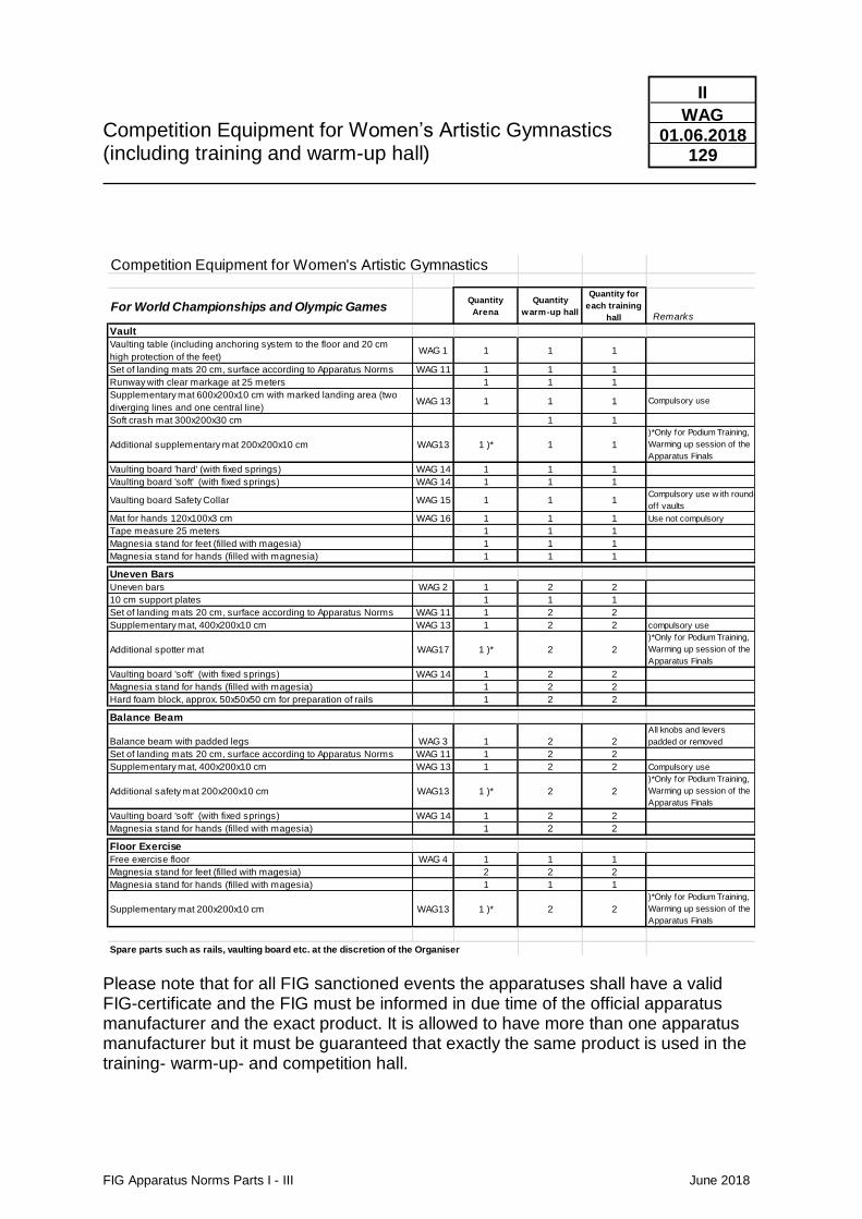
Competition Equipment for Women’s Artistic Gymnastics (including training and warm-up hall)
FIG Apparatus Norms Parts I - III June 2018
II
WAG 01.06.2018
129
Please note that for all FIG sanctioned events the apparatuses shall have a valid FIG-certificate and the FIG must be informed in due time of the official apparatus manufacturer and the exact product. It is allowed to have more than one apparatus manufacturer but it must be guaranteed that exactly the same product is used in the training- warm-up- and competition hall.
Competition Equipment for Women's Artistic Gymnastics
For World Championships and Olympic GamesQuantity
Arena
Quantity
warm-up hall
Quantity for
each training
hall Remarks
Vault
Vaulting table (including anchoring system to the floor and 20 cm
high protection of the feet)WAG 1 1 1 1
Set of landing mats 20 cm, surface according to Apparatus Norms WAG 11 1 1 1
Runway with clear markage at 25 meters 1 1 1
Supplementary mat 600x200x10 cm with marked landing area (two
diverging lines and one central line)WAG 13 1 1 1 Compulsory use
Soft crash mat 300x200x30 cm 1 1
Additional supplementary mat 200x200x10 cm WAG13 1 )* 1 1
)*Only for Podium Training,
Warming up session of the
Apparatus Finals
Vaulting board 'hard' (with fixed springs) WAG 14 1 1 1
Vaulting board 'soft' (with fixed springs) WAG 14 1 1 1
Vaulting board Safety Collar WAG 15 1 1 1Compulsory use w ith round-
off vaults
Mat for hands 120x100x3 cm WAG 16 1 1 1 Use not compulsory
Tape measure 25 meters 1 1 1
Magnesia stand for feet (filled with magesia) 1 1 1
Magnesia stand for hands (filled with magnesia) 1 1 1
Uneven Bars
Uneven bars WAG 2 1 2 2
10 cm support plates 1 1 1
Set of landing mats 20 cm, surface according to Apparatus Norms WAG 11 1 2 2
Supplementary mat, 400x200x10 cm WAG 13 1 2 2 compulsory use
Additional spotter mat WAG17 1 )* 2 2
)*Only for Podium Training,
Warming up session of the
Apparatus Finals
Vaulting board 'soft' (with fixed springs) WAG 14 1 2 2
Magnesia stand for hands (filled with magesia) 1 2 2
Hard foam block, approx. 50x50x50 cm for preparation of rails 1 2 2
Balance Beam
Balance beam with padded legs WAG 3 1 2 2
All knobs and levers
padded or removed
Set of landing mats 20 cm, surface according to Apparatus Norms WAG 11 1 2 2
Supplementary mat, 400x200x10 cm WAG 13 1 2 2 Compulsory use
Additional safety mat 200x200x10 cm WAG13 1 )* 2 2
)*Only for Podium Training,
Warming up session of the
Apparatus Finals
Vaulting board 'soft' (with fixed springs) WAG 14 1 2 2
Magnesia stand for hands (filled with magesia) 1 2 2
Floor Exercise
Free exercise floor WAG 4 1 1 1
Magnesia stand for feet (filled with magesia) 2 2 2
Magnesia stand for hands (filled with magesia) 1 1 1
Supplementary mat 200x200x10 cm WAG13 1 )* 2 2
)*Only for Podium Training,
Warming up session of the
Apparatus Finals
Spare parts such as rails, vaulting board etc. at the discretion of the Organiser
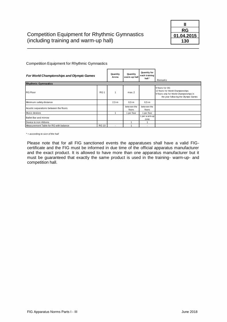
Competition Equipment for Rhythmic Gymnastics (including training and warm-up hall)
FIG Apparatus Norms Parts I - III June 2018
II
RG 01.04.2015
130
Please note that for all FIG sanctioned events the apparatuses shall have a valid FIG-certificate and the FIG must be informed in due time of the official apparatus manufacturer and the exact product. It is allowed to have more than one apparatus manufacturer but it must be guaranteed that exactly the same product is used in the training- warm-up- and competition hall.
Competition Equipment for Rhythmic Gymnastics
For World Championships and Olympic GamesQuantity
Arena
Quantity
warm-up hall
Quantity for
each training
hall * Remarks
Rhythmic Gymnastics
RG Floor RG 1 1 max. 2
9 floors for OG
12 floors for World Championships
9 floors only for World Championships in
the year follow ing the Olympic Games
Minimum safety distance 2,5 m 0,5 m 0,5 m
Acustic separations between the floorsbetw een the
f loors
betw een the
f loors
Music devices 1 1 per f loor 1 per f loor
Ballet Bar and mirrow1 per w arm-up
zone
Device to iron ribbons 1 1
Measurement Table for RG with balance RG 10 - 1 -
* = according to size of the hall
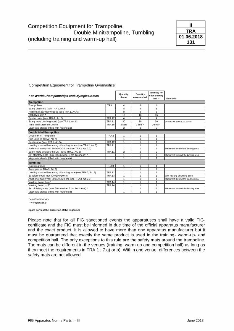
Competition Equipment for Trampoline, Double Minitrampoline, Tumbling (including training and warm-up hall)
FIG Apparatus Norms Parts I - III June 2018
II
TRA 01.06.2018
131
Please note that for all FIG sanctioned events the apparatuses shall have a valid FIG-certificate and the FIG must be informed in due time of the official apparatus manufacturer and the exact product. It is allowed to have more than one apparatus manufacturer but it must be guaranteed that exactly the same product is used in the training- warm-up- and competition hall. The only exceptions to this rule are the safety mats around the trampoline. The mats can be different in the venues (training, warm up and competition hall) as long as they meet the requirements in TRA 1 ; 7.a) or b). Within one venue, differences between the safety mats are not allowed.
Competition Equipment for Trampoline Gymnastics
For World Championships and Olympic GamesQuantity
Arena
Quantity
warm-up hall
Quantity for
each training
hall ** Remarks
Trampoline
Trampolines TRA 1 4 4 4
Safety platforms (see TRA 1, Art. 6) 8 8 8
Platform mats with wedges (see TRA 1, Art. 6) 8 8 8
Stability plates * 16 16 16
Spotter mats (see TRA 1, Art. 7) TRA 12 4 4 4
Safety mats on the ground (see TRA 1, Art. 8) TRA 11 30 30 30 30 mats of 300x200x20 cm
Time Measurement Device TRA 15 2 sets 2 sets * 2 sets *
Magnesia stands (filled with magnesia) 2 2 2
Double Mini-Trampoline
Double Mini-Trampoline TRA 2 1 1 1
Run-up (see TRA 2, Art. 4) 1 1 1
Spotter-mat (see TRA 2, Art. 5) TRA 12 1 1 1
Landing mats with marking of landing zones (see TRA 2, Art. 3) TRA 11 1 1 1
Additional safety mat 300x200x20 cm (see TRA 2, Art. 3.2) 1 1 1 Placement: behind the landing area
Safety mats besides the DMT (see TRA 2, Art. 6) TRA 11 2 2 2
Set of Safety mats (min. 50 cm wide; 5 cm thickness) * 1 1 1 Placement: around the landing area
Magnesia stands (filled with magnesia) 1 1 1
Tumbling
Tumbling track TRA 3 1 1 1
Run-up (see TRA 3, Art. 3) 1 1 1
Landing mats with marking of landing zone (see TRA 3, Art. 2) TRA 11 1 1 1
Supplementary mat 400x200x10 cm TRA 13 1 1 1 With marking of landing zone
Additional safety mat 300x200x20 cm (see TRA 3, Art. 2.2) 1 1 1 Placement: behind the landing area
Vaulting board 'hard' TRA 14 1 1 1
Vaulting board 'soft' TRA 14 1 1 1
Set of Safety mats (min. 50 cm wide; 5 cm thickness) * 1 1 1 Placement: around the landing area
Magnesia stands (filled with magnesia) 1 1 1
* = not compulsory
** = if applicable
Spare parts at the discretion of the Organiser

FIG Apparatus Norms Parts I - III June 2018
FÉDÉRATION INTERNATIONALE
DE GYMNASTIQUE
III Certificates and diplomas
Content
FIG Apparatus Norms Parts I - III June 2018
III
01.01.2018 1
Page
1. Each apparatus must have a valid FIG Certificate III/3 2. Validity of the Certificate III/3 3. Rights of the Apparatus Manufacturer with a valid FIG Certificate III/3 4. Procedure to obtain a Certificate III/3 4.1 Recognition of the FIG Statutes, Rules and Regulations, Applicable law and arbitration, Code of Auto discipline 4.2 Declaration concerning harmful substances 4.3 Practical Test 4.4 Testing by an FIG recognised Testing Institute 4.5 Issuing of FIG Certificate 5. Testing Fees of the FIG recognised Testing Institutes III/5 6. Fee for the Certificates III/5 7. Obtaining a certificate without testing for apparatus produced by another manufacturer III/5 8. FIG Diploma III/6 9. Reward for the suppliers of World Championships and III/6
World Cup Finals 10. Renewal of Certificates III/6 11. New Apparatus, Modified Apparatus, New Developments III/7 12. Publication of the FIG Certificates and Diplomas III/7 13. FIG Sticker - FIG APPROVED III/7 14. Control of apparatus at the competitions III/8 Re-testing of apparatus by the FIG at the Testing Institute 15. FIG recognised Testing Institutes III/8 16. Publicity and manufacturer's logo on apparatus III/9 17. Waiver of Liability III/9 18. Current Fees for FIG-Certificates III/9 19. Code of Auto discipline III/9
Content
FIG Apparatus Norms Parts I - III June 2018
III
01.01.2018 2
Page Appendix 1 Directives for the Use of
Official FIG Designations and Logos III/10 Appendix 2 FIG Recognised Testing Institutes
Addresses and Contact Persons III/14 Appendix 3 FIG Recognised Testing Institutes III/15 What can be tested where? Appendix 4 Testing Fees of the FIG Recognised Testing Institutes III/16
Appendix 5 Code of Auto discipline III/18 Appendix 6 Intermediate Rules III/26
FIG Apparatus Norms Parts I - III June 2018
III
01.01.2018 3
1. Each apparatus must have a valid FIG Certificate The definition of «Apparatus» for these Apparatus Norms is: All apparatus used at FIG competitions and listed in these Apparatus Norms. Each apparatus, including all hand apparatus used in Rhythmic Gymnastics, must
have its own, valid Certificate, to be used at FIG events, Olympic Games, World Games and international events.
For Olympic Games, World Championships, World Games and other multi-sports games (e.g. Commonwealth Games, Asian Games, Panam Games, University Games), the apparatus must have a valid certificate at least 1 year prior to the competitions. For all other competitions, the certificates must be valid at the latest at the moment of the invitation. Example: World Cup / World Challenge Cup: 3 months prior to the competitions.
2. Validity of the Certificate The Certificates have a validity of two years. The expiry date is indicated on the
certificate. The FIG may, at any time, prolong or shorten the validity of issued Certificates or
withdraw a Certificate. 3. Rights of the Apparatus Manufacturer with a valid FIG Certificate When receiving a FIG Certificate, the apparatus manufacturer obtains the following
rights:
• The right that the respective apparatus may be used at all official events of the FIG, its Continental Unions and member federations, as well as at the Olympic Games and World Games.
• The right to use the designation and the logo «FIG Approved» together in the catalogue and other publicity material, as prescribed in the respective directives of the FIG. (see Appendix 1)
• The use of the sticker « FIG Approved » on the respective apparatus.
• The regular publication in the list of certified apparatus in the FIG Bulletin and on FIG’s website.
• One free advertisement (1 x ½ page, black and white) in the FIG Bulletin during the period of validity of each Certificate.
4. Procedure to obtain a FIG Certificate The procedure consists of five steps:
• Declaration to be bound by the FIG’s Statutes, Rules and Regulations as well as the provisions concerning governing law and arbitration
• Declaration of safety regarding chemical additives and any other harmful material or substances
• Practical test
• Testing at one of the FIG recognised Testing Institutes
• Issuing of the Certificate by the FIG
FIG Apparatus Norms Parts I - III June 2018
III
01.01.2018 4
4.1 Recognition of the FIG Statutes, Rules and Regulations
Applicable law and arbitration Code of Auto discipline Apparatus manufacturers who wish an FIG Certificate have to confirm in writing, that they recognise and strictly follow the FIG Statutes, Rules and Regulations. For their relationship with the FIG, the Testing Institutes, FIG’s member federations, the Continental Unions and the organising committees, the apparatus manufacturer must accept to be governed by Swiss law and in case of disputes, to resolve such disputes to the exclusion of the ordinary courts by arbitration.
The following declaration must be made and signed: «We herewith confirm unequivocally to respect and strictly follow the FIG Statutes, Technical Regulations, Code of Points, Apparatus Norms including the Code of Auto discipline, the Rules for Advertising and Publicity the Accreditation Rules, the Directives and Work plans of the competitions and all other Rules and Regulations published on FIG’s website. This commitment is valid as long as we have a valid Certificate. » «All disputes arising out of or in connection with the Apparatus Norms, the testing and/or certification of our apparatus and in the relationship with the FIG, or one of their recognised Testing Institutes, Member Federations or Organising Committees shall be resolved, to the exclusion of the ordinary courts by an Arbitration Tribunal constituted in accordance with the Statutes and Regulations of the Court of Arbitration of Sport in Lausanne, Switzerland. We hereby undertake to comply with the said Statutes and Regulation, and to enforce in good faith the award to be rendered. The decision of the Arbitration Tribunal shall be final and binding on the parties.»
4.2 Declaration of safety regarding chemical additives and any other harmful material or substances Apparatus manufacturers who wish to obtain a certificate, must confirm the following in a written declaration: “We herewith confirm that all our products do not contain any known hazardous or harmful substances, material, and chemical additives and that they are of no health risk whatsoever for the intended use.”
4.3 Practical Test
Apparatus manufacturers who wish a Certificate must first have their apparatus tested practically by gymnasts and coaches. For this purpose, the manufacturer contacts directly the FIG Secretary General who, on a case by case bases, assigns one or several FIG’s member federations, which will test the apparatus in a training centre by elite gymnasts. The apparatus must be tested under competition conditions. The manufacturer must provide a confirmation signed by the President or Secretary General of respective the member federation(s) containing the following:
FIG Apparatus Norms Parts I - III June 2018
III
01.01.2018 5
«We confirm to have tested apparatus X under competition conditions at our training centre and/or at competitions. The apparatus is of the best quality, safe and suitable to be used at international competitions. We recommend that the FIG initiates the necessary procedures that this apparatus may be used at future international events. »
4.4 Testing by an FIG recognised Testing Institute
After the successful practical test by an FIG member federation, the apparatus must be announced at the FIG Secretary General to be tested by one of the FIG’s recognised Testing Institutes. For contact persons and addresses see Appendix 2). The Testing Institute informs the apparatus manufacturer and the FIG in writing, when the apparatus will be tested. The Testing Institute tests the apparatus following the norms and testing procedures and prepares and submits a test report on behalf of the FIG and the apparatus manufacturer. Manufacturers can raise an objection against descriptions and dimensions of their equipment in the test report within a period of 2 weeks after receiving the report. All costs in connection with the testing (transport and testing fee) are the responsibility of the apparatus manufacturer and have to be paid prior to the tests. (Testing fees see Appendix 4). For equipment with no existing test procedures the testing is done by the responsible Technical Committee after presentation of the confirmation according to 4.3. All costs are the responsibility of the apparatus manufacturer. The testing shall be announced to the FIG Secretary General.
4.5 Issuing of FIG Certificates The FIG Certificate will be issued by the Secretary General, provided the following conditions are met:
• Confirmation / declaration from the manufacturer to recognise the FIG Statutes, Rules and Regulations and confirmation concerning applicable law and arbitration (see 4.1)
• Declaration of safety regarding chemical additives and any other harmful material or substances (see 4.2)
• The confirmation/recommendation from a member federation concerning the practical test. (see 4.3).
• A positive test report from one of the FIG recognised Testing Institutes.
• Payment of the test fee and the Certificate fee. 5. Testing fees of the FIG recognised Testing Institutes The testing fees must be approved by the FIG and must be identical at all FIG
recognised Testing Institutes. The testing fees valid at this time are published in Appendix 4.
The Testing Institutes invoice the Apparatus Manufacturer directly with the testing fees and taxes and must be prepaid.
6. Fee for the Certificate The fee to be paid to the FIG to obtain a Certificate and the attached rights are listed in
Part III, § 18 and § 3.
FIG Apparatus Norms Parts I - III June 2018
III
01.01.2018 6
This fee is decided by the Executive Committee and may be adjusted every two years if necessary.
This fee must be paid by the Apparatus Manufactures in advance to the FIG. 7. Obtaining a certificate without testing for apparatus produced by another
manufacturer Apparatus manufacturers and retailers may obtain an FIG certificate in their name to sell apparatus produced by another manufacturer according to the following conditions:
• Written approval from the apparatus manufacturer who has produced and tested his
apparatus and has a valid certificate.
• Payment of the fee to the FIG for the requested certificate as per Art. 18 of Part III of
the FIG Apparatus Norms
• The validity of the certificate cannot exceed the expiry of the original certificate of the
manufacturer who has tested the apparatus
• The manufacturer who produces the apparatus may withdraw his approval at any
time with written notification to FIG
• The certificate cannot be extended without approval from the manufacturer who
produces the apparatus
The description of the apparatus on the certificate must contain the name of the apparatus and an article number which is identical to the one listed in the catalogue. It must also bear the name of the manufacturer as well as the article number and name of the respective apparatus
8. FIG Diploma Manufacturers, who are in possession of 12 or more valid Certificates, receive a FIG
Diploma free of charge. The Diploma is valid as long as the manufacturer has 12 or more valid Certificates.
The FIG Diploma gives the apparatus manufacturer the following additional rights:
• The right to have two VIP accreditations to the official FIG Competitions
• The right to attend the FIG Congress, Council, Gala and Symposium
• The right to be represented directly or indirectly to Apparatus Commission at the discretion of the FIG President (see art. 15.2 and 23 of FIG Statutes)
• The right to bear the designation «Official FIG Partner» and to use this on his letter head and promotional material.
• The right, to use the FIG Logo on his letter head and catalogue. The directives (Appendix 1) must be followed.
• A free advertisement (1 x 1/1 page, in colour) in World of Gymnastics every second year.
• A free advertisement in the FIG Bulletin (1 x 1/1 page, black and white) every second year.
• To be mentioned in the list of the Official FIG Partners and official Sponsors, this is published in every Bulletin, in the Directory and on the FIG website.
• The publication of the manufacturer’s logo in a composite page together with the official FIG sponsors in every issue of World of Gymnastics.
• A free advertisement (1/1 page, black and white) in the respective Code of Points
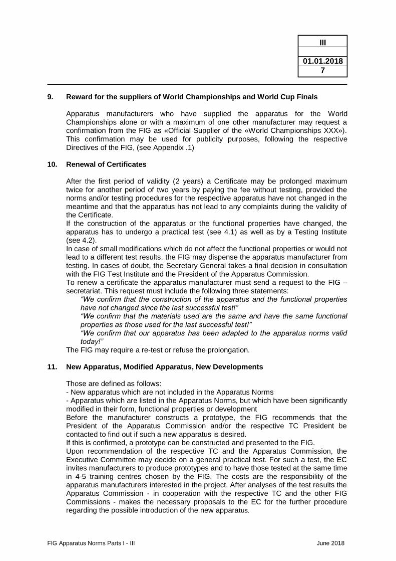
FIG Apparatus Norms Parts I - III June 2018
III
01.01.2018 7
9. Reward for the suppliers of World Championships and World Cup Finals Apparatus manufacturers who have supplied the apparatus for the World Championships alone or with a maximum of one other manufacturer may request a confirmation from the FIG as «Official Supplier of the «World Championships XXX»). This confirmation may be used for publicity purposes, following the respective Directives of the FIG, (see Appendix .1)
10. Renewal of Certificates After the first period of validity (2 years) a Certificate may be prolonged maximum
twice for another period of two years by paying the fee without testing, provided the norms and/or testing procedures for the respective apparatus have not changed in the meantime and that the apparatus has not lead to any complaints during the validity of the Certificate.
If the construction of the apparatus or the functional properties have changed, the apparatus has to undergo a practical test (see 4.1) as well as by a Testing Institute (see 4.2).
In case of small modifications which do not affect the functional properties or would not lead to a different test results, the FIG may dispense the apparatus manufacturer from testing. In cases of doubt, the Secretary General takes a final decision in consultation with the FIG Test Institute and the President of the Apparatus Commission.
To renew a certificate the apparatus manufacturer must send a request to the FIG – secretariat. This request must include the following three statements:
“We confirm that the construction of the apparatus and the functional properties have not changed since the last successful test!” “We confirm that the materials used are the same and have the same functional properties as those used for the last successful test!” “We confirm that our apparatus has been adapted to the apparatus norms valid today!”
The FIG may require a re-test or refuse the prolongation. 11. New Apparatus, Modified Apparatus, New Developments Those are defined as follows: - New apparatus which are not included in the Apparatus Norms - Apparatus which are listed in the Apparatus Norms, but which have been significantly
modified in their form, functional properties or development Before the manufacturer constructs a prototype, the FIG recommends that the
President of the Apparatus Commission and/or the respective TC President be contacted to find out if such a new apparatus is desired.
If this is confirmed, a prototype can be constructed and presented to the FIG. Upon recommendation of the respective TC and the Apparatus Commission, the
Executive Committee may decide on a general practical test. For such a test, the EC invites manufacturers to produce prototypes and to have those tested at the same time in 4-5 training centres chosen by the FIG. The costs are the responsibility of the apparatus manufacturers interested in the project. After analyses of the test results the Apparatus Commission - in cooperation with the respective TC and the other FIG Commissions - makes the necessary proposals to the EC for the further procedure regarding the possible introduction of the new apparatus.
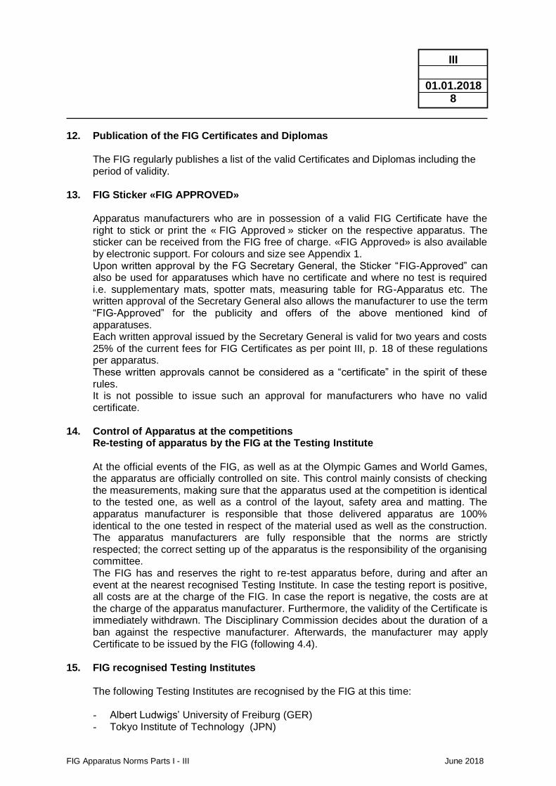
FIG Apparatus Norms Parts I - III June 2018
III
01.01.2018 8
12. Publication of the FIG Certificates and Diplomas The FIG regularly publishes a list of the valid Certificates and Diplomas including the
period of validity. 13. FIG Sticker «FIG APPROVED» Apparatus manufacturers who are in possession of a valid FIG Certificate have the
right to stick or print the « FIG Approved » sticker on the respective apparatus. The sticker can be received from the FIG free of charge. «FIG Approved» is also available by electronic support. For colours and size see Appendix 1. Upon written approval by the FG Secretary General, the Sticker “FIG-Approved” can also be used for apparatuses which have no certificate and where no test is required i.e. supplementary mats, spotter mats, measuring table for RG-Apparatus etc. The written approval of the Secretary General also allows the manufacturer to use the term “FIG-Approved” for the publicity and offers of the above mentioned kind of apparatuses. Each written approval issued by the Secretary General is valid for two years and costs 25% of the current fees for FIG Certificates as per point III, p. 18 of these regulations per apparatus. These written approvals cannot be considered as a “certificate” in the spirit of these rules. It is not possible to issue such an approval for manufacturers who have no valid certificate.
14. Control of Apparatus at the competitions Re-testing of apparatus by the FIG at the Testing Institute At the official events of the FIG, as well as at the Olympic Games and World Games,
the apparatus are officially controlled on site. This control mainly consists of checking the measurements, making sure that the apparatus used at the competition is identical to the tested one, as well as a control of the layout, safety area and matting. The apparatus manufacturer is responsible that those delivered apparatus are 100% identical to the one tested in respect of the material used as well as the construction. The apparatus manufacturers are fully responsible that the norms are strictly respected; the correct setting up of the apparatus is the responsibility of the organising committee.
The FIG has and reserves the right to re-test apparatus before, during and after an event at the nearest recognised Testing Institute. In case the testing report is positive, all costs are at the charge of the FIG. In case the report is negative, the costs are at the charge of the apparatus manufacturer. Furthermore, the validity of the Certificate is immediately withdrawn. The Disciplinary Commission decides about the duration of a ban against the respective manufacturer. Afterwards, the manufacturer may apply Certificate to be issued by the FIG (following 4.4).
15. FIG recognised Testing Institutes The following Testing Institutes are recognised by the FIG at this time:
- Albert Ludwigs’ University of Freiburg (GER) - Tokyo Institute of Technology (JPN)
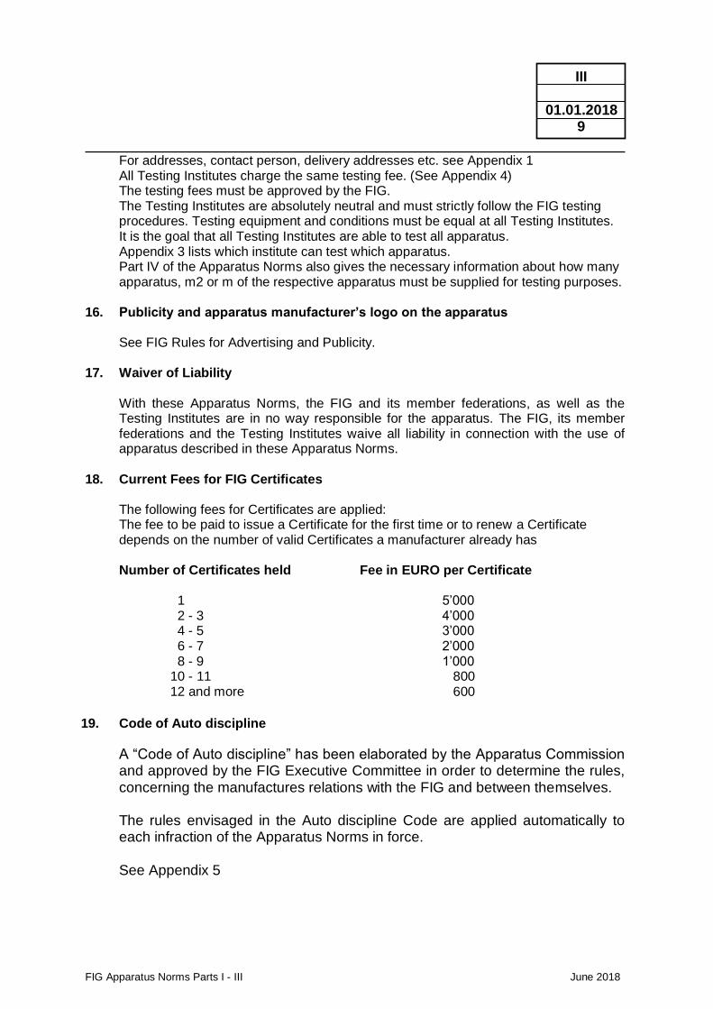
FIG Apparatus Norms Parts I - III June 2018
III
01.01.2018 9
For addresses, contact person, delivery addresses etc. see Appendix 1 All Testing Institutes charge the same testing fee. (See Appendix 4) The testing fees must be approved by the FIG. The Testing Institutes are absolutely neutral and must strictly follow the FIG testing
procedures. Testing equipment and conditions must be equal at all Testing Institutes. It is the goal that all Testing Institutes are able to test all apparatus. Appendix 3 lists which institute can test which apparatus. Part IV of the Apparatus Norms also gives the necessary information about how many
apparatus, m2 or m of the respective apparatus must be supplied for testing purposes. 16. Publicity and apparatus manufacturer’s logo on the apparatus See FIG Rules for Advertising and Publicity. 17. Waiver of Liability
With these Apparatus Norms, the FIG and its member federations, as well as the Testing Institutes are in no way responsible for the apparatus. The FIG, its member federations and the Testing Institutes waive all liability in connection with the use of apparatus described in these Apparatus Norms.
18. Current Fees for FIG Certificates
The following fees for Certificates are applied: The fee to be paid to issue a Certificate for the first time or to renew a Certificate depends on the number of valid Certificates a manufacturer already has
Number of Certificates held Fee in EURO per Certificate
1 5’000 2 - 3 4’000 4 - 5 3’000 6 - 7 2’000 8 - 9 1’000 10 - 11 800 12 and more 600
19. Code of Auto discipline
A “Code of Auto discipline” has been elaborated by the Apparatus Commission and approved by the FIG Executive Committee in order to determine the rules, concerning the manufactures relations with the FIG and between themselves.
The rules envisaged in the Auto discipline Code are applied automatically to each infraction of the Apparatus Norms in force. See Appendix 5
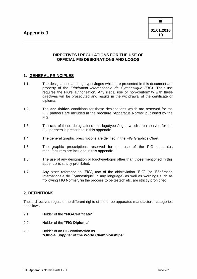
Appendix 1
FIG Apparatus Norms Parts I - III June 2018
III
01.01.2016 10
DIRECTIVES / REGULATIONS FOR THE USE OF OFFICIAL FIG DESIGNATIONS AND LOGOS
1. GENERAL PRINCIPLES
1.1. The designations and logotypes/logos which are presented in this document are property of the Fédération Internationale de Gymnastique (FIG). Their use requires the FIG's authorization. Any illegal use or non-conformity with these directives will be prosecuted and results in the withdrawal of the certificate or diploma.
1.2. The acquisition conditions for these designations which are reserved for the
FIG partners are included in the brochure "Apparatus Norms" published by the FIG.
1.3. The use of these designations and logotypes/logos which are reserved for the
FIG partners is prescribed in this appendix. 1.4. The general graphic prescriptions are defined in the FIG Graphics Chart. 1.5. The graphic prescriptions reserved for the use of the FIG apparatus
manufacturers are included in this appendix. 1.6. The use of any designation or logotype/logos other than those mentioned in this
appendix is strictly prohibited. 1.7. Any other reference to “FIG”, use of the abbreviation “FIG” (or “Fédération
Internationale de Gymnastique” in any language) as well as wordings such as “following FIG Norms”, “in the process to be tested” etc. are strictly prohibited.
2. DEFINITIONS These directives regulate the different rights of the three apparatus manufacturer categories as follows: 2.1. Holder of the "FIG-Certificate" 2.2. Holder of the "FIG-Diploma" 2.3. Holder of an FIG confirmation as "Official Supplier of the World Championships"
Appendix 1
FIG Apparatus Norms Parts I - III June 2018
III
01.01.2016 11
3. HOLDER OF THE FIG-CERTIFICATE The holder of the" FIG Certificate" may use the logotype "FIG Approved" respecting the following conditions: 3.1. The logotype may only and exclusively be associated with only one element
respectively one single article, apparatus or accessory duly certified by the FIG. 3.2. It may be used on an article respectively an apparatus or an accessory itself or it
may be integrated in any type of advertising or publicity but only in direct connection or relation with the respective certified apparatus. The logotype may also appear in a description of the certified apparatus (advertisement, publicity leaflet etc.)
3.3. It may not be used as an isolated element, separate from the apparatus. 3.4. Consequently it may not appear on letter heads, cover pages of catalogues, or in
editorial articles with advertising purposes, nor in any other institutional documents containing general information.
3.5. Graphics
3.5.1. Logotype FIG Approved: (respect the size as per 3.6.1)
3.5.2. Colours According to the range defined by the FIG Graphics Chart.
• Black
• Blue Pantone 3005 U
• Red Warm red CV 3.6. Use and size / Maximum dimensions 3.6.1. On printed matters
Formats: A5 14.8 x 21.0 cm ø 08 mm max. A4 21.0 x 29.7 cm ø 12 mm max. A3 29.7 x 42.0 cm ø 18 mm max. A2 42.0 x 59.4 cm ø 35 mm max. A1 59.4 x 84.1 cm ø 60 mm max.
Appendix 1
FIG Apparatus Norms Parts I - III June 2018
III
01.01.2016 12
3.6.2. On the apparatus The logotype "FIG Approved" may only be applied to the support surfaces
(supports, legs of apparatus) of the apparatus. Maximum diameter is 35 mm.
On the floor and on the mats the logotype may appear in one of the four corners with a maximum distance of 5 cm to the corner or on the side of the floor/mat with the exception of the surfaces which are reserved for advertising purposes as defined in the "FIG Rules for Advertising and Publicity ". Maximum diameter is 35 mm.
On the apparatus for rhythmic gymnastics the logotype/sticker "FIG Approved"
is described in RG, 2, 3, 4, 5 and 6, pages 71/72 in chapter II of the FIG Apparatus Norms.
4. HOLDER OF THE FIG DIPLOMA 4.1. The right to use the designation "Official FIG Partner" subject to article 1.5 of
the "FIG Rules for Advertising and Publicity". 4.2. The right to use the FIG Logo for advertising purposes only, strictly respecting
the FIG Graphics Chart. In addition to the rights listed in chapter 3, the holder of a FIG Diploma obtains:
FIG Logo: 4.3. The title "Official FIG Partner" and the FIG logotype may by no means be used
directly attached to or with a product but only with the company name or identity of the holder of the FIG Diploma. (e.g.: letter heads, envelopes, cover pages of catalogues, various kinds of printed material, newsletters, "give aways" etc.)
Appendix 1
FIG Apparatus Norms Parts I - III June 2018
III
01.01.2016 13
5. HOLDER OF AN FIG CONFIRMATION AS "OFFICIAL SUPPLIER FOR THE WORLD CHAMPIONSHIPS" 5.1. The apparatus manufacturer who has been duly confirmed by the FIG may use
the designation "Official Supplier of the World Championships X" 5.2. The use of the above-mentioned designation (for advertising purposes only) can
only be associated with the supplied apparatus and also with the company name of the manufacturer. (e.g.: letter heads, envelopes, cover pages of catalogues, various kinds of printed material, newsletters, "give aways" etc.)
5.3. The above-mentioned designation may be used together with the FIG logotype
according to the regulations of the FIG Graphics Chart and within the following dimensions:
5.4. Formats: A5 14.8 x 21.0 cm Ø 8 mm max. A4 21.0 x 29.7 cm Ø 12 mm max. A3 29.7 x 42.0 cm Ø 18 mm max. A2 42.0 x 59.4 cm Ø 35 mm max. A1 59.4 x 84.1 cm Ø 60 mm max. RECOMMENDATION We strongly recommend that the holder of a certificate or a diploma should send his drafts of all printed matters to the FIG to be proof-read prior to printing.
Appendix 2
FIG Apparatus Norms Parts I - III June 2018
III
01.06.2018 14
FIG RECOGNISED TESTING INSTITUTES
ADDRESSES AND CONTACT PERSONS Albert Ludwigs University Institute of Sport and Sport Science - GYMLAB Schwarzwaldstrasse 175 D-79117 Freiburg i. Br. Germany Phone +49 761 203 4554 e-mail [email protected] Contact Person Daniel Fesser Tokyo Institute of Technology Faculty of Engineering Department of Architecture and Building Engineering FIG Norm Testing Laboratory (Ono Lab.) 2-12-1 O-okayama Meguro-ku Tokyo 152-8552 Japan Fax +81 3 5734 3164 Phone +81 3 5734 3164 E-mail
[email protected] Contact Person Takamasa Mikami
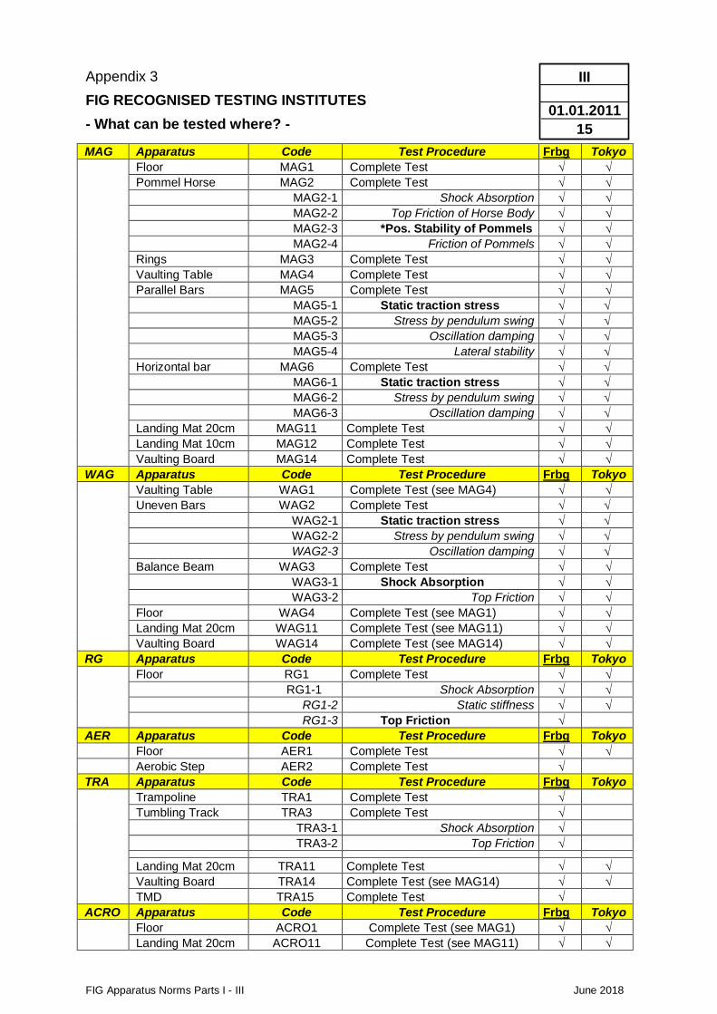
Appendix 3
FIG RECOGNISED TESTING INSTITUTES
- What can be tested where? -
FIG Apparatus Norms Parts I - III June 2018
III
01.01.2011
15
MAG Apparatus Code Test Procedure Frbg Tokyo
Floor MAG1 Complete Test
Pommel Horse MAG2 Complete Test
MAG2-1 Shock Absorption
MAG2-2 Top Friction of Horse Body
MAG2-3 *Pos. Stability of Pommels
MAG2-4 Friction of Pommels
Rings MAG3 Complete Test
Vaulting Table MAG4 Complete Test
Parallel Bars MAG5 Complete Test
MAG5-1 Static traction stress MAG5-2 Stress by pendulum swing MAG5-3 Oscillation damping MAG5-4 Lateral stability Horizontal bar MAG6 Complete Test MAG6-1 Static traction stress MAG6-2 Stress by pendulum swing MAG6-3 Oscillation damping Landing Mat 20cm MAG11 Complete Test
Landing Mat 10cm MAG12 Complete Test
Vaulting Board MAG14 Complete Test
WAG Apparatus Code Test Procedure Frbg Tokyo
Vaulting Table WAG1 Complete Test (see MAG4)
Uneven Bars WAG2 Complete Test WAG2-1 Static traction stress WAG2-2 Stress by pendulum swing WAG2-3 Oscillation damping Balance Beam WAG3 Complete Test
WAG3-1 Shock Absorption
WAG3-2 Top Friction
Floor WAG4 Complete Test (see MAG1)
Landing Mat 20cm WAG11 Complete Test (see MAG11)
Vaulting Board WAG14 Complete Test (see MAG14)
RG Apparatus Code Test Procedure Frbg Tokyo
Floor RG1 Complete Test
RG1-1 Shock Absorption
RG1-2 Static stiffness
RG1-3 Top Friction
AER Apparatus Code Test Procedure Frbg Tokyo
Floor AER1 Complete Test
Aerobic Step AER2 Complete Test
TRA Apparatus Code Test Procedure Frbg Tokyo
Trampoline TRA1 Complete Test
Tumbling Track TRA3 Complete Test
TRA3-1 Shock Absorption
TRA3-2 Top Friction
Landing Mat 20cm TRA11 Complete Test
Vaulting Board TRA14 Complete Test (see MAG14)
TMD TRA15 Complete Test
ACRO Apparatus Code Test Procedure Frbg Tokyo
Floor ACRO1 Complete Test (see MAG1)
Landing Mat 20cm ACRO11 Complete Test (see MAG11)
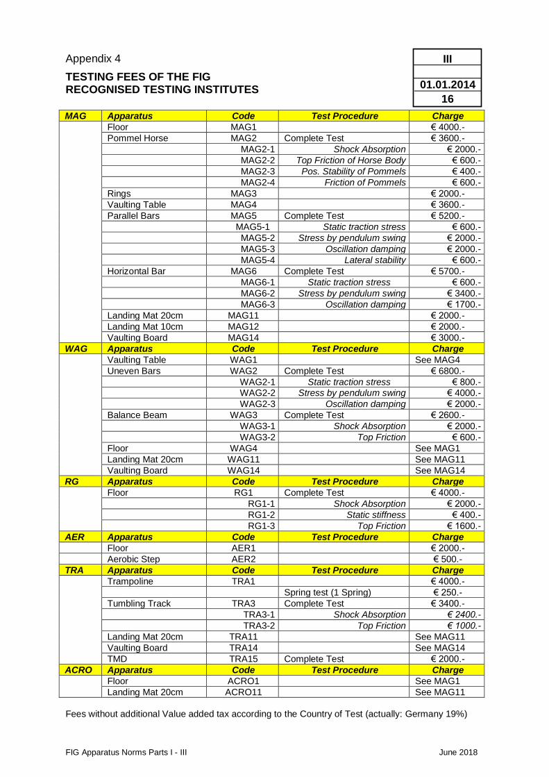
Appendix 4
TESTING FEES OF THE FIG RECOGNISED TESTING INSTITUTES
FIG Apparatus Norms Parts I - III June 2018
III
01.01.2014
16
MAG Apparatus Code Test Procedure Charge
Floor MAG1 € 4000.-
Pommel Horse MAG2 Complete Test € 3600.-
MAG2-1 Shock Absorption € 2000.-
MAG2-2 Top Friction of Horse Body € 600.-
MAG2-3 Pos. Stability of Pommels € 400.-
MAG2-4 Friction of Pommels € 600.-
Rings MAG3 € 2000.-
Vaulting Table MAG4 € 3600.-
Parallel Bars MAG5 Complete Test € 5200.-
MAG5-1 Static traction stress € 600.-
MAG5-2 Stress by pendulum swing € 2000.-
MAG5-3 Oscillation damping € 2000.-
MAG5-4 Lateral stability € 600.-
Horizontal Bar MAG6 Complete Test € 5700.-
MAG6-1 Static traction stress € 600.-
MAG6-2 Stress by pendulum swing € 3400.-
MAG6-3 Oscillation damping € 1700.-
Landing Mat 20cm MAG11 € 2000.-
Landing Mat 10cm MAG12 € 2000.-
Vaulting Board MAG14 € 3000.-
WAG Apparatus Code Test Procedure Charge
Vaulting Table WAG1 See MAG4
Uneven Bars WAG2 Complete Test € 6800.-
WAG2-1 Static traction stress € 800.-
WAG2-2 Stress by pendulum swing € 4000.-
WAG2-3 Oscillation damping € 2000.-
Balance Beam WAG3 Complete Test € 2600.-
WAG3-1 Shock Absorption € 2000.-
WAG3-2 Top Friction € 600.-
Floor WAG4 See MAG1
Landing Mat 20cm WAG11 See MAG11
Vaulting Board WAG14 See MAG14
RG Apparatus Code Test Procedure Charge
Floor RG1 Complete Test € 4000.-
RG1-1 Shock Absorption € 2000.-
RG1-2 Static stiffness € 400.-
RG1-3 Top Friction € 1600.-
AER Apparatus Code Test Procedure Charge
Floor AER1 € 2000.-
Aerobic Step AER2 € 500.-
TRA Apparatus Code Test Procedure Charge
Trampoline TRA1 € 4000.-
Spring test (1 Spring) € 250.-
Tumbling Track TRA3 Complete Test € 3400.-
TRA3-1 Shock Absorption € 2400.-
TRA3-2 Top Friction € 1000.-
Landing Mat 20cm TRA11 See MAG11
Vaulting Board TRA14 See MAG14
TMD TRA15 Complete Test € 2000.-
ACRO Apparatus Code Test Procedure Charge
Floor ACRO1 See MAG1
Landing Mat 20cm ACRO11 See MAG11
Fees without additional Value added tax according to the Country of Test (actually: Germany 19%)
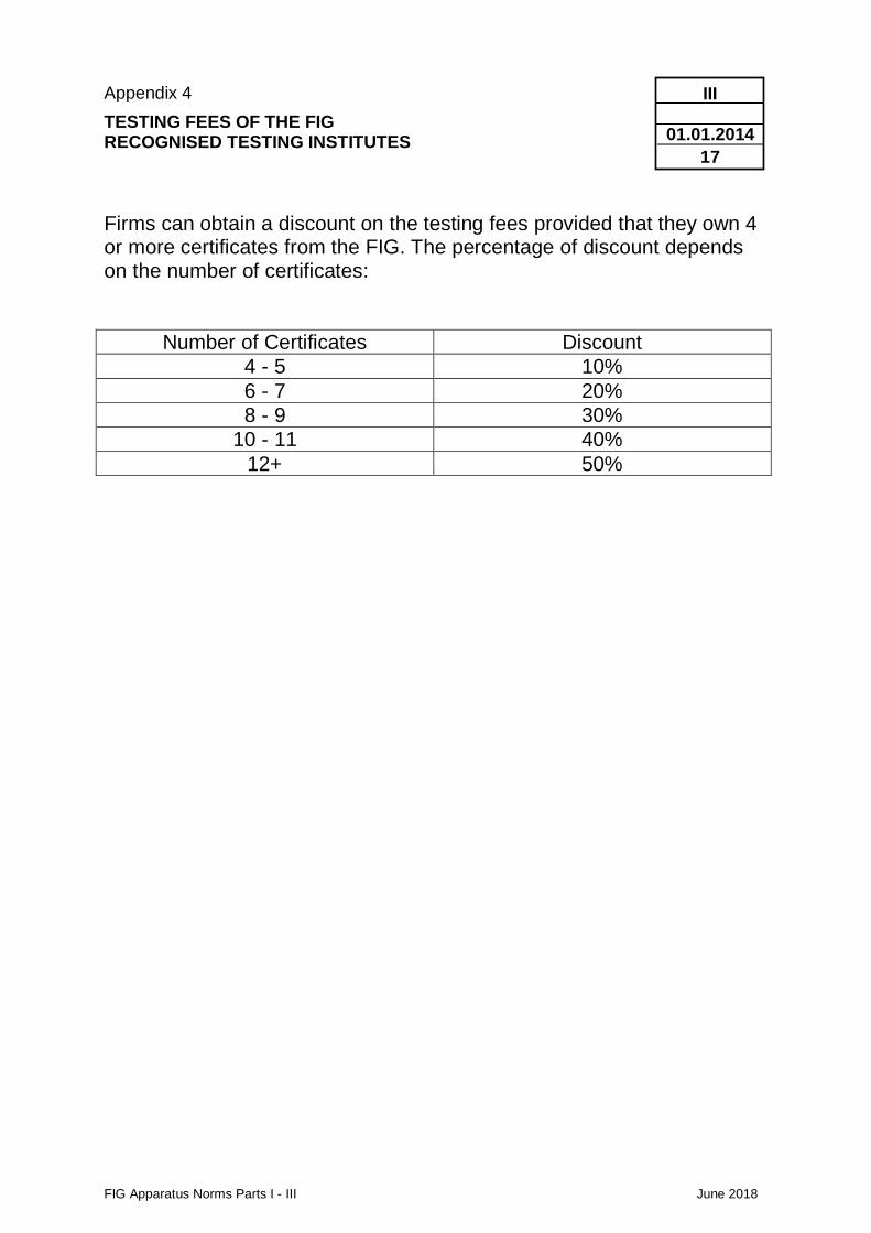
Appendix 4
TESTING FEES OF THE FIG RECOGNISED TESTING INSTITUTES
FIG Apparatus Norms Parts I - III June 2018
III
01.01.2014
17
Firms can obtain a discount on the testing fees provided that they own 4 or more certificates from the FIG. The percentage of discount depends on the number of certificates:
Number of Certificates Discount
4 - 5 10%
6 - 7 20%
8 - 9 30%
10 - 11 40%
12+ 50%
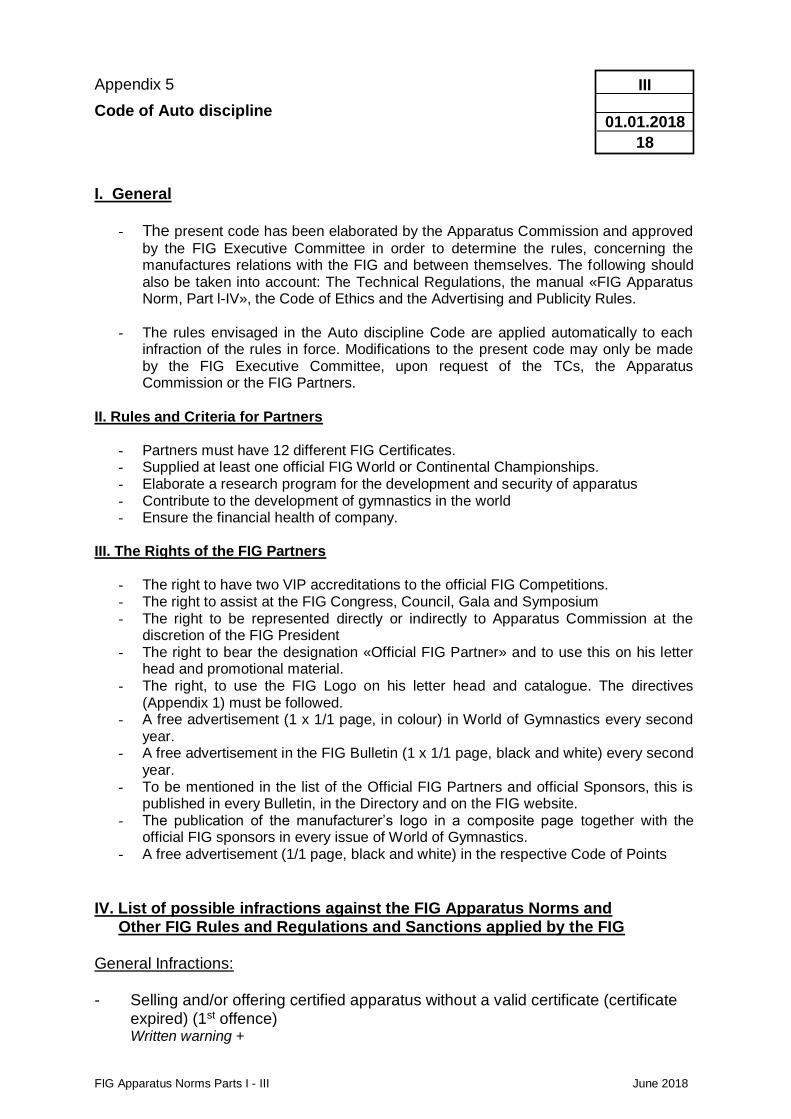
Appendix 5
Code of Auto discipline
FIG Apparatus Norms Parts I - III June 2018
III
01.01.2018
18
I. General
- The present code has been elaborated by the Apparatus Commission and approved
by the FIG Executive Committee in order to determine the rules, concerning the manufactures relations with the FIG and between themselves. The following should also be taken into account: The Technical Regulations, the manual «FIG Apparatus Norm, Part l-IV», the Code of Ethics and the Advertising and Publicity Rules.
- The rules envisaged in the Auto discipline Code are applied automatically to each
infraction of the rules in force. Modifications to the present code may only be made by the FIG Executive Committee, upon request of the TCs, the Apparatus Commission or the FIG Partners.
II. Rules and Criteria for Partners
- Partners must have 12 different FIG Certificates. - Supplied at least one official FIG World or Continental Championships. - Elaborate a research program for the development and security of apparatus - Contribute to the development of gymnastics in the world - Ensure the financial health of company.
III. The Rights of the FIG Partners
- The right to have two VIP accreditations to the official FIG Competitions. - The right to assist at the FIG Congress, Council, Gala and Symposium - The right to be represented directly or indirectly to Apparatus Commission at the
discretion of the FIG President - The right to bear the designation «Official FIG Partner» and to use this on his letter
head and promotional material. - The right, to use the FIG Logo on his letter head and catalogue. The directives
(Appendix 1) must be followed. - A free advertisement (1 x 1/1 page, in colour) in World of Gymnastics every second
year. - A free advertisement in the FIG Bulletin (1 x 1/1 page, black and white) every second
year. - To be mentioned in the list of the Official FIG Partners and official Sponsors, this is
published in every Bulletin, in the Directory and on the FIG website. - The publication of the manufacturer’s logo in a composite page together with the
official FIG sponsors in every issue of World of Gymnastics. - A free advertisement (1/1 page, black and white) in the respective Code of Points
IV. List of possible infractions against the FIG Apparatus Norms and
Other FIG Rules and Regulations and Sanctions applied by the FIG General Infractions: - Selling and/or offering certified apparatus without a valid certificate (certificate
expired) (1st offence) Written warning +
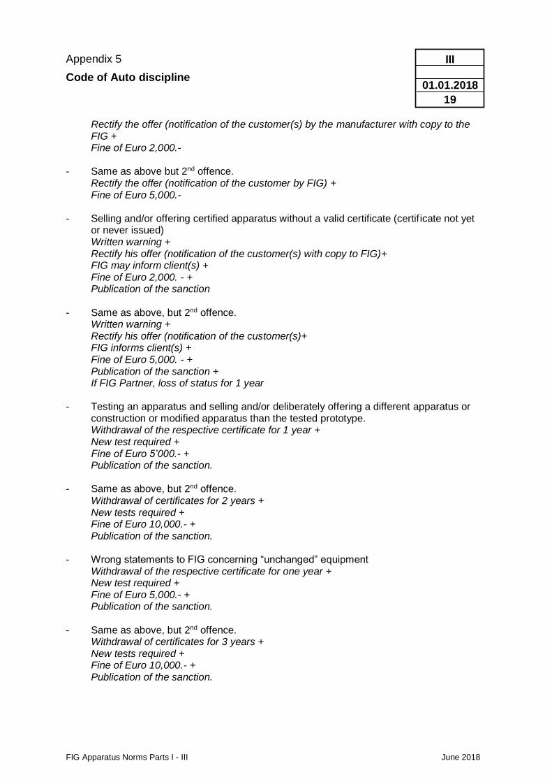
Appendix 5
Code of Auto discipline
FIG Apparatus Norms Parts I - III June 2018
III
01.01.2018
19
Rectify the offer (notification of the customer(s) by the manufacturer with copy to the FIG +
Fine of Euro 2,000.- - Same as above but 2nd offence. Rectify the offer (notification of the customer by FIG) + Fine of Euro 5,000.- - Selling and/or offering certified apparatus without a valid certificate (certif icate not yet
or never issued) Written warning + Rectify his offer (notification of the customer(s) with copy to FIG)+ FIG may inform client(s) + Fine of Euro 2,000. - + Publication of the sanction - Same as above, but 2nd offence. Written warning + Rectify his offer (notification of the customer(s)+ FIG informs client(s) + Fine of Euro 5,000. - + Publication of the sanction + If FIG Partner, loss of status for 1 year - Testing an apparatus and selling and/or deliberately offering a different apparatus or
construction or modified apparatus than the tested prototype. Withdrawal of the respective certificate for 1 year + New test required + Fine of Euro 5’000.- + Publication of the sanction. - Same as above, but 2nd offence. Withdrawal of certificates for 2 years + New tests required + Fine of Euro 10,000.- + Publication of the sanction. - Wrong statements to FIG concerning “unchanged” equipment Withdrawal of the respective certificate for one year + New test required + Fine of Euro 5,000.- + Publication of the sanction. - Same as above, but 2nd offence. Withdrawal of certificates for 3 years + New tests required + Fine of Euro 10,000.- + Publication of the sanction.
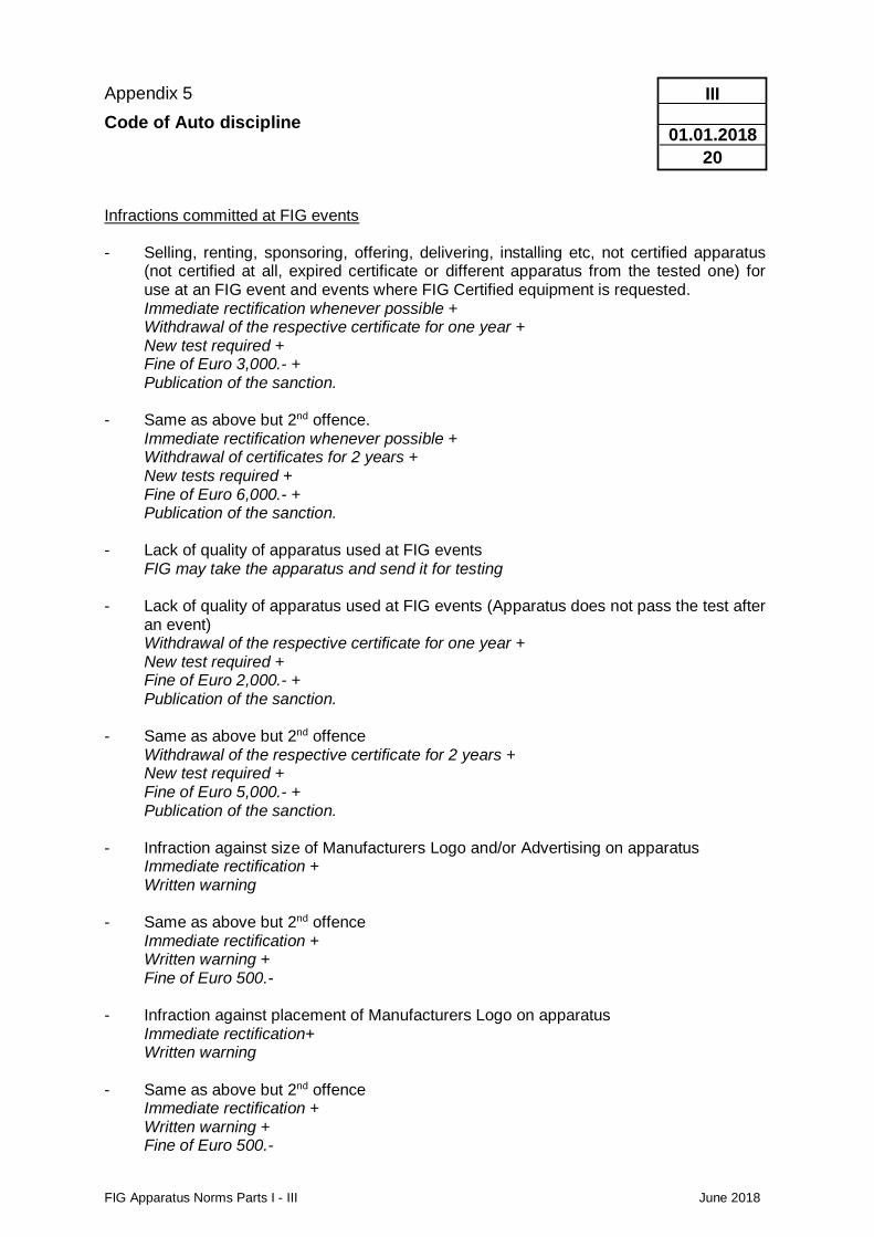
Appendix 5
Code of Auto discipline
FIG Apparatus Norms Parts I - III June 2018
III
01.01.2018
20
Infractions committed at FIG events - Selling, renting, sponsoring, offering, delivering, installing etc, not certified apparatus
(not certified at all, expired certificate or different apparatus from the tested one) for use at an FIG event and events where FIG Certified equipment is requested.
Immediate rectification whenever possible + Withdrawal of the respective certificate for one year + New test required + Fine of Euro 3,000.- + Publication of the sanction. - Same as above but 2nd offence. Immediate rectification whenever possible + Withdrawal of certificates for 2 years + New tests required + Fine of Euro 6,000.- + Publication of the sanction. - Lack of quality of apparatus used at FIG events FIG may take the apparatus and send it for testing - Lack of quality of apparatus used at FIG events (Apparatus does not pass the test after
an event) Withdrawal of the respective certificate for one year + New test required + Fine of Euro 2,000.- + Publication of the sanction. - Same as above but 2nd offence Withdrawal of the respective certificate for 2 years + New test required + Fine of Euro 5,000.- + Publication of the sanction. - Infraction against size of Manufacturers Logo and/or Advertising on apparatus Immediate rectification + Written warning - Same as above but 2nd offence Immediate rectification + Written warning + Fine of Euro 500.- - Infraction against placement of Manufacturers Logo on apparatus Immediate rectification+ Written warning - Same as above but 2nd offence
Immediate rectification + Written warning + Fine of Euro 500.-
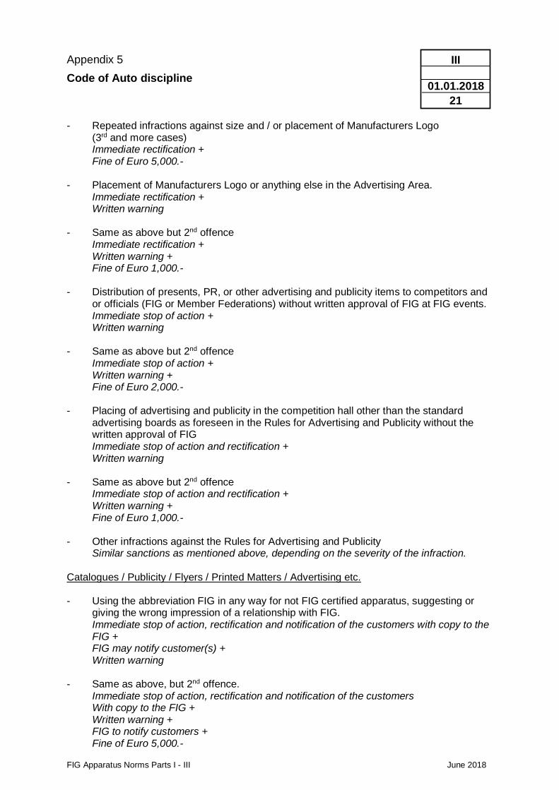
Appendix 5
Code of Auto discipline
FIG Apparatus Norms Parts I - III June 2018
III
01.01.2018
21
- Repeated infractions against size and / or placement of Manufacturers Logo (3rd and more cases) Immediate rectification + Fine of Euro 5,000.- - Placement of Manufacturers Logo or anything else in the Advertising Area. Immediate rectification + Written warning - Same as above but 2nd offence Immediate rectification + Written warning + Fine of Euro 1,000.- - Distribution of presents, PR, or other advertising and publicity items to competitors and
or officials (FIG or Member Federations) without written approval of FIG at FIG events. Immediate stop of action + Written warning - Same as above but 2nd offence Immediate stop of action + Written warning + Fine of Euro 2,000.- - Placing of advertising and publicity in the competition hall other than the standard
advertising boards as foreseen in the Rules for Advertising and Publicity without the written approval of FIG
Immediate stop of action and rectification + Written warning - Same as above but 2nd offence Immediate stop of action and rectification + Written warning + Fine of Euro 1,000.- - Other infractions against the Rules for Advertising and Publicity Similar sanctions as mentioned above, depending on the severity of the infraction. Catalogues / Publicity / Flyers / Printed Matters / Advertising etc. - Using the abbreviation FIG in any way for not FIG certified apparatus, suggesting or
giving the wrong impression of a relationship with FIG. Immediate stop of action, rectification and notification of the customers with copy to the
FIG + FIG may notify customer(s) + Written warning - Same as above, but 2nd offence. Immediate stop of action, rectification and notification of the customers With copy to the FIG + Written warning + FIG to notify customers + Fine of Euro 5,000.-
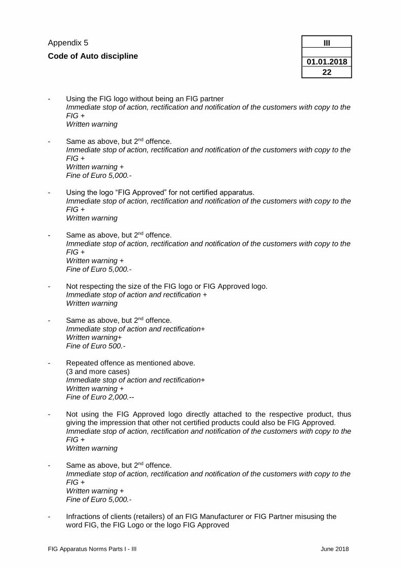
Appendix 5
Code of Auto discipline
FIG Apparatus Norms Parts I - III June 2018
III
01.01.2018
22
- Using the FIG logo without being an FIG partner Immediate stop of action, rectification and notification of the customers with copy to the
FIG + Written warning - Same as above, but 2nd offence. Immediate stop of action, rectification and notification of the customers with copy to the
FIG + Written warning + Fine of Euro 5,000.- - Using the logo “FIG Approved” for not certified apparatus. Immediate stop of action, rectification and notification of the customers with copy to the
FIG + Written warning - Same as above, but 2nd offence. Immediate stop of action, rectification and notification of the customers with copy to the
FIG + Written warning + Fine of Euro 5,000.- - Not respecting the size of the FIG logo or FIG Approved logo. Immediate stop of action and rectification + Written warning - Same as above, but 2nd offence.
Immediate stop of action and rectification+ Written warning+ Fine of Euro 500.-
- Repeated offence as mentioned above. (3 and more cases)
Immediate stop of action and rectification+ Written warning + Fine of Euro 2,000.--
- Not using the FIG Approved logo directly attached to the respective product, thus
giving the impression that other not certified products could also be FIG Approved. Immediate stop of action, rectification and notification of the customers with copy to the FIG + Written warning
- Same as above, but 2nd offence.
Immediate stop of action, rectification and notification of the customers with copy to the FIG + Written warning + Fine of Euro 5,000.-
- Infractions of clients (retailers) of an FIG Manufacturer or FIG Partner misusing the
word FIG, the FIG Logo or the logo FIG Approved
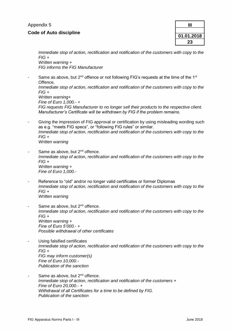
Appendix 5
Code of Auto discipline
FIG Apparatus Norms Parts I - III June 2018
III
01.01.2018
23
Immediate stop of action, rectification and notification of the customers with copy to the FIG +
Written warning + FIG informs the FIG Manufacturer - Same as above, but 2nd offence or not following FIG’s requests at the time of the 1st
Offence, Immediate stop of action, rectification and notification of the customers with copy to the
FIG + Written warning+ Fine of Euro 1,000.- + FIG requests FIG Manufacturer to no longer sell their products to the respective client.
Manufacturer’s Certificate will be withdrawn by FIG if the problem remains. - Giving the impression of FIG approval or certification by using misleading wording such
as e.g. “meets FIG specs”, or “following FIG rules” or similar. Immediate stop of action, rectification and notification of the customers with copy to the
FIG + Written warning - Same as above, but 2nd offence. Immediate stop of action, rectification and notification of the customers with copy to the
FIG + Written warning + Fine of Euro 1,000.- - Reference to “old” and/or no longer valid certificates or former Diplomas Immediate stop of action, rectification and notification of the customers with copy to the
FIG + Written warning - Same as above, but 2nd offence. Immediate stop of action, rectification and notification of the customers with copy to the
FIG + Written warning + Fine of Euro 5’000.- + Possible withdrawal of other certificates - Using falsified certificates Immediate stop of action, rectification and notification of the customers with copy to the
FIG + FIG may inform customer(s) Fine of Euro 10,000.- Publication of the sanction - Same as above, but 2nd offence. Immediate stop of action, rectification and notification of the customers + Fine of Euro 20,000.- + Withdrawal of all Certificates for a time to be defined by FIG. Publication of the sanction
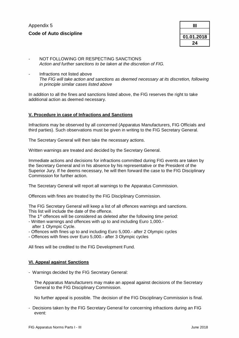
Appendix 5
Code of Auto discipline
FIG Apparatus Norms Parts I - III June 2018
III
01.01.2018
24
- NOT FOLLOWING OR RESPECTING SANCTIONS
Action and further sanctions to be taken at the discretion of FIG. - Infractions not listed above The FIG will take action and sanctions as deemed necessary at its discretion, following
in principle similar cases listed above In addition to all the fines and sanctions listed above, the FIG reserves the right to take additional action as deemed necessary. V. Procedure in case of Infractions and Sanctions Infractions may be observed by all concerned (Apparatus Manufacturers, FIG Officials and third parties). Such observations must be given in writing to the FIG Secretary General. The Secretary General will then take the necessary actions. Written warnings are treated and decided by the Secretary General. Immediate actions and decisions for infractions committed during FIG events are taken by the Secretary General and in his absence by his representative or the President of the Superior Jury. If he deems necessary, he will then forward the case to the FIG Disciplinary Commission for further action. The Secretary General will report all warnings to the Apparatus Commission. Offences with fines are treated by the FIG Disciplinary Commission. The FIG Secretary General will keep a list of all offences warnings and sanctions. This list will include the date of the offence. The 1st offences will be considered as deleted after the following time period: - Written warnings and offences with up to and including Euro 1,000.- after 1 Olympic Cycle. - Offences with fines up to and including Euro 5,000.- after 2 Olympic cycles - Offences with fines over Euro 5,000.- after 3 Olympic cycles All fines will be credited to the FIG Development Fund. VI. Appeal against Sanctions - Warnings decided by the FIG Secretary General:
The Apparatus Manufacturers may make an appeal against decisions of the Secretary General to the FIG Disciplinary Commission. No further appeal is possible. The decision of the FIG Disciplinary Commission is final.
- Decisions taken by the FIG Secretary General for concerning infractions during an FIG
event:
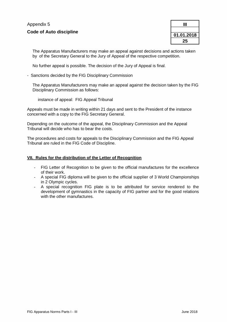
Appendix 5
Code of Auto discipline
FIG Apparatus Norms Parts I - III June 2018
III
01.01.2018
25
The Apparatus Manufacturers may make an appeal against decisions and actions taken by of the Secretary General to the Jury of Appeal of the respective competition. No further appeal is possible. The decision of the Jury of Appeal is final.
- Sanctions decided by the FIG Disciplinary Commission
The Apparatus Manufacturers may make an appeal against the decision taken by the FIG Disciplinary Commission as follows:
instance of appeal: FIG Appeal Tribunal
Appeals must be made in writing within 21 days and sent to the President of the instance concerned with a copy to the FIG Secretary General. Depending on the outcome of the appeal, the Disciplinary Commission and the Appeal Tribunal will decide who has to bear the costs. The procedures and costs for appeals to the Disciplinary Commission and the FIG Appeal Tribunal are ruled in the FIG Code of Discipline. VII. Rules for the distribution of the Letter of Recognition
- FIG Letter of Recognition to be given to the official manufactures for the excellence of their work.
- A special FIG diploma will be given to the official supplier of 3 World Championships in 2 Olympic cycles.
- A special recognition FIG plate is to be attributed for service rendered to the development of gymnastics in the capacity of FIG partner and for the good relations with the other manufactures.
Appendix 6
Intermediate Rules
FIG Apparatus Norms Parts I - III June 2018
III
01.01.2014
26
Intermediate Rules re.
FIG Apparatus Norms Parts I - III June 2018
Impressum Edition 2017: Publisher Fédération Internationale de Gymnastique Responsible FIG - Apparatus Commission Drawings Karl - Heinz Schwirtz / Ludwig Schweizer Translations FIG Secretariat / GYMLAB – University of Freiburg © Fédération Internationale de Gymnastique


![External Commercial Borrowings [ECBs] norms.pdf(SIDBI). iv. Units in Special Economic Zones (SEZs). v. Export Import Bank of India (Exim Bank) (only under the approval route). vi](https://img.pdfslide.us/doc/110x75/5e6c84979a2deb128012d053/external-commercial-borrowings-ecbs-normspdf-sidbi-iv-units-in-special-economic.jpg)