Embed Size (px)
Citation preview

This solution guide describes the disaster recovery modular add-on to the
Federation Enterprise Hybrid Cloud Foundation solution for SAP. It introduces
the solution architecture and features that ensure disaster recovery of SAP
services and operations in the cloud.
October 2015

2
Copyright © 2015 EMC Corporation. All rights reserved. Published in the USA.
Published October 2015
EMC believes the information in this publication is accurate as of its publication date. The
information is subject to change without notice.
THE INFORMATION IN THIS PUBLICATION IS PROVIDED AS IS. EMC CORPORATION MAKES
NO REPRESENTATIONS OR WARRANTIES OF ANY KIND WITH RESPECT TO THE
INFORMATION IN THIS PUBLICATION, AND SPECIFICALLY DISCLAIMS IMPLIED
WARRANTIES OF MERCHANTABILITY OR FITNESS FOR A PARTICULAR PURPOSE. Use,
copying, and distribution of any EMC software described in this publication requires an
applicable software license.
EMC2, EMC, VMAX, VNX, ViPR, RecoverPoint, and the EMC logo are registered
trademarks or trademarks of EMC Corporation in the United States and other
countries. All other trademarks used herein are the property of their respective
owners.
For the most up-to-date listing of EMC product names, see EMC Corporation Trademarks
on EMC.com.
Federation Enterprise Hybrid Cloud 3.1 — Data Protection for SAP: Disaster Recovery
Solution Guide
Part Number H14563
Contents
3
Chapter 1 Executive Summary ............................................................. 4
Document purpose .............................................................................................. 5
Audience ............................................................................................................ 5
Essential reading ................................................................................................ 5
Solution purpose ................................................................................................. 5
The business challenge ........................................................................................ 5
The technology solution ....................................................................................... 6
Terminology ....................................................................................................... 6
Chapter 2 Solution Overview ................................................................ 8
Overview ........................................................................................................... 9
Storage ......................................................................................................... 9
Orchestration ................................................................................................. 9
Solution architecture ........................................................................................... 9
Logical architecture ......................................................................................... 9
DR operational cycle ...................................................................................... 11
Software resources ............................................................................................ 14
Chapter 3 Use Cases and Validation .................................................... 15
Overview .......................................................................................................... 16
Implementing DR for SAP applications .................................................................. 16
Composing an SAP provisioning service on DR-enabled infrastructure .................. 16
Setting costs for DR-enabled storage ............................................................... 19
Validation.......................................................................................................... 21
Use case 1: Failover after disaster ................................................................... 22
Use case 2: Reprotection for Data Center B ...................................................... 25
Use case 3: Planned migration ........................................................................ 26
Use case 4: Reprotection for Data Center A ...................................................... 27
Use case 5: Test recovery ............................................................................... 28
Chapter 4 Conclusion ........................................................................ 30
Conclusion ........................................................................................................ 31
Appendix A References ........................................................................ 32
References ........................................................................................................ 33
EMC documentation ....................................................................................... 33
Other product documentation .......................................................................... 33

Chapter 1: Executive Summary
4
This chapter presents the following topics:
Document purpose .............................................................................................. 5
Audience ............................................................................................................ 5
Essential reading ................................................................................................ 5
Solution purpose ................................................................................................. 5
The business challenge ........................................................................................ 5
The technology solution ....................................................................................... 6
Terminology ....................................................................................................... 6
Chapter 1: Executive Summary
5
This solution guide describes a disaster recovery (DR) add-on solution for the Federation
Enterprise Hybrid Cloud for SAP. It is a companion to the Federation Enterprise Hybrid Cloud
3.1: Foundation for SAP Solution Guide.
The guide:
Introduces the technical components needed to implement and operate the
solution
Describes EMC’s testing and validation of the solution’s functionality
Evaluates the technical and business value of the solution
This guide is intended for executives, managers, SAP architects, cloud administrators, and
technical administrators of IT environments who want to implement DR for a hybrid cloud
infrastructure-as-a-service (IaaS) platform for managing SAP landscapes. Readers should be
familiar with the VMware® vRealizeTM Suite of products, storage technologies, and general IT
functions and requirements and how they fit into a hybrid cloud architecture.
This guide provides critical reference information for planning and designing a data
protection solution for the hybrid cloud. To understand the concepts, architecture, and
functionalities of the Federation Enterprise Hybrid Cloud and how to operate SAP on top of
it, you are advised to read the following documents:
Federation Enterprise Hybrid Cloud 3.1: Foundation for SAP Solution Guide
Federation Enterprise Hybrid Cloud 3.1: Foundation Infrastructure Reference
Architecture Guide
Federation Enterprise Hybrid Cloud 3.1: Concepts and Architecture Solution Guide
Federation Enterprise Hybrid Cloud 3.1: Operations Solution Guide
Federation Enterprise Hybrid Cloud 3.1: Security Management Solution Guide
Organizations using SAP as a major part of their core business operations require a business
continuity strategy to manage risks and prepare for recovery in the event of a disaster. The
plan should include specific measures for:
Safeguarding the continuity of business operations and protecting revenue
Recovering systems to at least a minimum level of operation if an outage occurs
A business continuity strategy has three components: backup, continuous availability (CA),
and disaster recovery (DR). This solution focuses on the DR component, which aims to
increase the availability of SAP landscapes and provide rapid recovery after a severe,
isolated technical failure in one or more infrastructure or application components.
Enterprises are increasingly transferring mission-critical SAP applications to cloud
infrastructures to gain cost savings, simplified management, and data center efficiencies.

Chapter 1: Executive Summary
6
DR is essential for mission-critical SAP applications. At the same time, a proper strategy
typically requires a significant time and budget investment to meet a company’s recovery
time objectives (RTOs) and recovery point objectives (RPOs) during disasters. The
challenges of designing DR-capable solutions include:
Ensuring RTOs and RPOs for a variety of SAP applications in different organizations in a cloud environment
Performing periodic recovery plan testing without incurring a huge cost or disruption to the business
Minimizing the manual work and reconfiguration effort needed to prepare another site for DR
Minimizing the human intervention needed to carry out DR for hundreds of systems
Ensuring “application consistency” for a federated application landscape
This solution addresses these challenges by offering automated rapid DR for SAP
applications running on the Federation Enterprise Hybrid Cloud.
The Federation Enterprise Hybrid Cloud integrates DR as a protection option for applications
and virtual machines. You can easily consume the DR option by selecting it when deploying
SAP applications from the vRealize Automation self-service catalog. The provisioning process
automatically places these systems on storage that is protected remotely by EMC
RecoverPoint®. Through tight integration with the EMC ViPR® Storage Replication Adapter,
VMware vCenter™ Site Recovery Manager™ interacts with EMC RecoverPoint and
orchestrates the whole DR process. The DR integration also automates the recovery of all
virtual storage and virtual machines at a recovery or failover site.
This DR solution for SAP provides:
Increased resilience during disasters by automating failover and failback and by orchestrating the startup sequences for SAP applications
Well-organized and highly coordinated recovery plans for a trouble-free failover
The convenience of triggering the failover and failback from any surviving site with a few clicks of a button
Minimized network overhead during replication
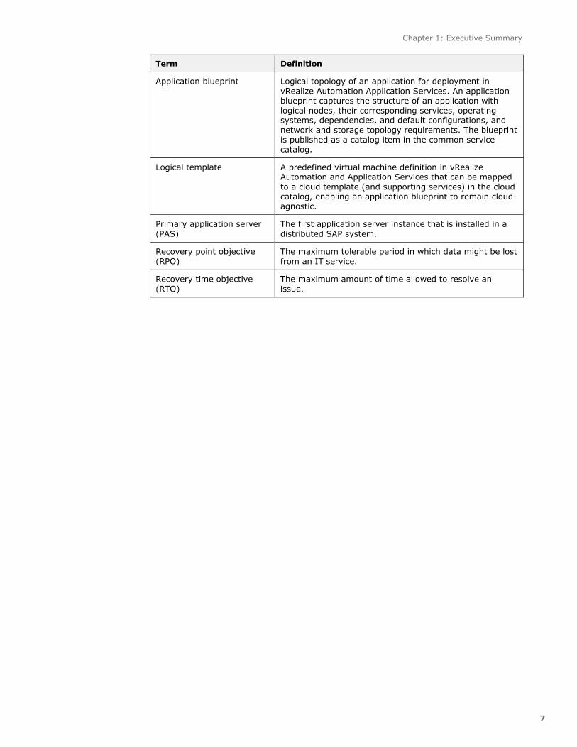
Table 1 defines key terms relevant to this solution that are used in this guide.
Terminology Table 1.
Term Definition
ABAP SAP Central Service
(ASCS)
An instance in a distributed SAP system that hosts the
message server and enqueuer server.
Additional application
server (AAS)
An SAP application server instance that is installed in a
distributed SAP system.
Chapter 1: Executive Summary
7
Term Definition
Application blueprint Logical topology of an application for deployment in vRealize Automation Application Services. An application blueprint captures the structure of an application with logical nodes, their corresponding services, operating systems, dependencies, and default configurations, and network and storage topology requirements. The blueprint is published as a catalog item in the common service catalog.
Logical template A predefined virtual machine definition in vRealize Automation and Application Services that can be mapped
to a cloud template (and supporting services) in the cloud catalog, enabling an application blueprint to remain cloud-agnostic.
Primary application server
(PAS)
The first application server instance that is installed in a
distributed SAP system.
Recovery point objective
(RPO)
The maximum tolerable period in which data might be lost
from an IT service.
Recovery time objective
(RTO)
The maximum amount of time allowed to resolve an
issue.

Chapter 2: Solution Overview
8
This chapter presents the following topics:
Overview ........................................................................................................... 9
Solution architecture ........................................................................................... 9
Software resources ............................................................................................ 14

Chapter 2: Solution Overview
9
This solution focuses on the implementation, management, and automation of DR for SAP
applications in the Federation Enterprise Hybrid Cloud. It builds on the proven design and
integration of EMC RecoverPoint and VMware vCenter Site Recovery Manager to offer the
following benefits in a hybrid cloud environment:
Continuous data protection for any point-in-time (PIT) recovery
Centralized recovery plans
Automated failover and failback
Nondisruptive testing
Planned migration
EMC VMAX® or VNX® storage systems provide the storage at two data centers: a primary
data center (Site A) and a recovery data center (Site B). The storage is presented to
RecoverPoint appliances (RPAs) at both sites. The RPAs replicate changes from the primary
site to the recovery site in accordance with predefined RPOs and RTOs. The storage is kept
synchronized between the two sites in an active/passive manner, with synchronization and
visibility coordinated by recovery plans in Site Recovery Manager.
VMware vCenter OrchestratorTM is central to all the customizations and operations used in
this solution. vCenter Orchestrator manages operations across several EMC and VMware
products, including:
EMC ViPR
EMC RecoverPoint
VMware vRealize Automation
VMware vCenter
VMware vCenter Site Recovery Manager
VMware NSX for vSphere
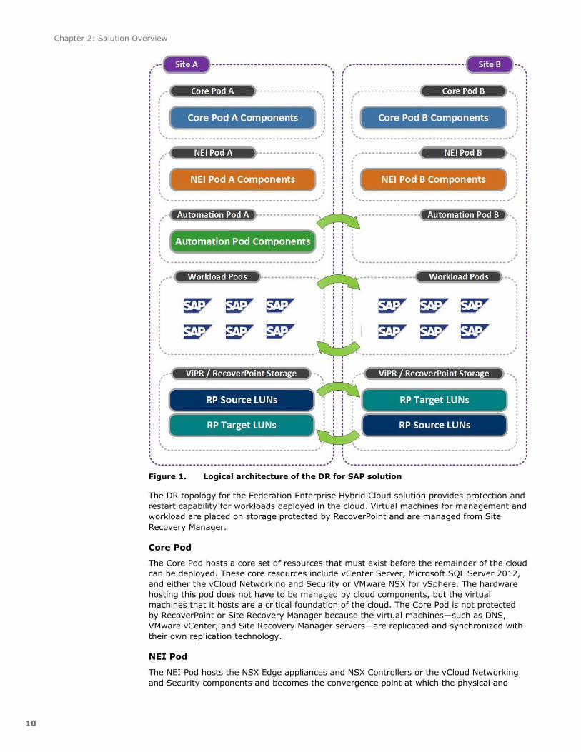
Figure 1 shows the logical architecture of the solution.
Storage
Orchestration
Logical
architecture
Chapter 2: Solution Overview
10
Figure 1. Logical architecture of the DR for SAP solution
The DR topology for the Federation Enterprise Hybrid Cloud solution provides protection and
restart capability for workloads deployed in the cloud. Virtual machines for management and
workload are placed on storage protected by RecoverPoint and are managed from Site
Recovery Manager.
Core Pod
The Core Pod hosts a core set of resources that must exist before the remainder of the cloud
can be deployed. These core resources include vCenter Server, Microsoft SQL Server 2012,
and either the vCloud Networking and Security or VMware NSX for vSphere. The hardware
hosting this pod does not have to be managed by cloud components, but the virtual
machines that it hosts are a critical foundation of the cloud. The Core Pod is not protected
by RecoverPoint or Site Recovery Manager because the virtual machines—such as DNS,
VMware vCenter, and Site Recovery Manager servers—are replicated and synchronized with
their own replication technology.
NEI Pod
The NEI Pod hosts the NSX Edge appliances and NSX Controllers or the vCloud Networking
and Security components and becomes the convergence point at which the physical and

Chapter 2: Solution Overview
11
virtual networks connect. The NEI Pod is not protected by RecoverPoint or Site Recovery
Manager. The objects in the NEI Pod are created manually to mirror functionality—such as
NSX distributed logical switches and routers, NSX dynamic routing, NSX security groups,
and NSX security policies (firewall rules)—between the two sites.
Automation Pod
The Automation Pod hosts the virtual machines that automate and manage the cloud
infrastructure that supports the workloads consumed by the cloud tenants. The Automation
Pod supports the components responsible for functions such as the user portal and
automated provisioning, monitoring, metering, and reporting.
Workload Pods
The Workload Pods are configured and assigned as shared resources in vRealize Automation,
to host SAP virtual machines deployed by the different business groups in the hybrid cloud
environment. These Workload Pods are deployed as VMware vSphere clusters in VMware
vCenter endpoints.
ViPR and RecoverPoint
Site Recovery Manager integrates with RecoverPoint storage replication and ViPR automated
storage services via EMC Storage Replication Adapters (SRAs). The SRAs control the
RecoverPoint replication process.
All protected systems undergo a series of six states from failover to failback. Figure 2 shows
transitions from one state to another: “S1” through “S6” represent the protection states at
the data centers (DCs).
DR operational
cycle
Chapter 2: Solution Overview
12
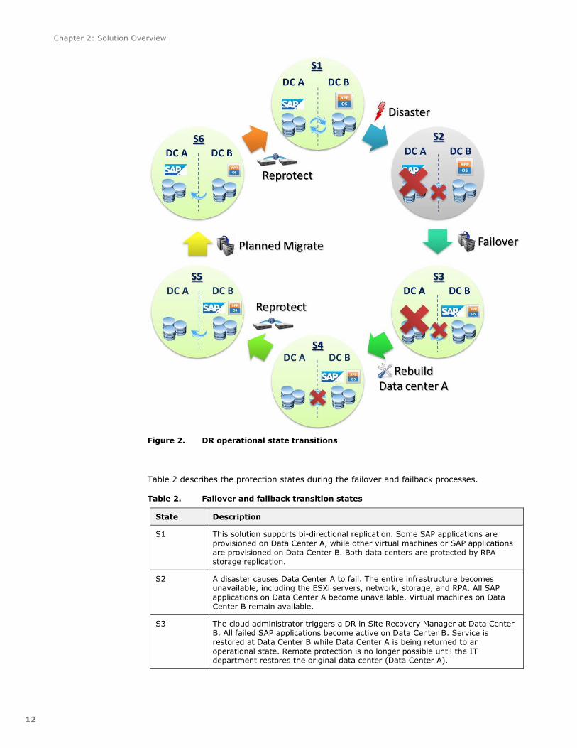
Figure 2. DR operational state transitions
Table 2 describes the protection states during the failover and failback processes.
Failover and failback transition states Table 2.
State Description
S1 This solution supports bi-directional replication. Some SAP applications are provisioned on Data Center A, while other virtual machines or SAP applications are provisioned on Data Center B. Both data centers are protected by RPA storage replication.
S2 A disaster causes Data Center A to fail. The entire infrastructure becomes unavailable, including the ESXi servers, network, storage, and RPA. All SAP applications on Data Center A become unavailable. Virtual machines on Data Center B remain available.
S3 The cloud administrator triggers a DR in Site Recovery Manager at Data Center B. All failed SAP applications become active on Data Center B. Service is restored at Data Center B while Data Center A is being returned to an operational state. Remote protection is no longer possible until the IT department restores the original data center (Data Center A).

Chapter 2: Solution Overview
13
State Description
S4 Data Center A recovers and becomes functional. The Site Recovery Manager server and vCenter server in Data Center A are back online and resynchronized with Data Center B. Storage replication has not yet started.
The effort required to rebuild and configure Data Center A depends on the impact on the site. In the worst case, where all hardware devices are irrecoverably damaged, a complete DC rebuild is necessary.
S5 The cloud administrator triggers a reprotect operation in Site Recovery Manager to replicate storage data from Data Center B to Data Center A. After reprotection, RPA protects both SAP applications and other virtual machines on Data Center B. No workloads run on Data Center A at this stage.
S6 A downtime maintenance operation is scheduled. The cloud administrator triggers a planned migration for SAP applications. After the planned migration, SAP applications run on Data Center A but have yet to re-establish replication as a final post-procedure.
Back to S1 Finally, reprotection is triggered again to restore the replication from Data Center A to Data Center B. When this operation is complete, Data Center A becomes protected once again and the environment is now considered to be fully restored to its normal state.

Chapter 2: Solution Overview
14
Table 3 lists the main elements of the six states during the failover and failback processes.
Major elements of the failover and failback processes Table 3.
State Activity Role of Data
Center A
Role of Data
Center B
Replication Workloads
run on
S1 Normal activity Production
Recovery
Recovery
Production
A -> B
B -> A
Data Center
A
Data Center B
S2 A full data center outage occurs after a disaster.
Outage Production None Data Center B
S3 Workloads fail
over to Data Center B.
Outage Production None Data Center
B
S4 IT rebuilds Data
Center A.
Standby Production None Data Center
B
S5 Reprotection Recovery Production B -> A Data Center
B
S6 Migrate workload back to Data Center A.
Production
Recovery
Production B -> A Data Center A
Data Center B
S1 Reprotection Production
Recovery
Recovery
Production
A -> B
B -> A
Data Center
A
Data Center B
Table 4 lists the software resources that are used in the solution.
Solution software resources Table 4.
Software Version Purpose
Federation Enterprise Hybrid Cloud, Foundation module
3.1.0 Customization package for storage as a service (STaaS) and foundation workflows
EMC Federation Enterprise Hybrid Cloud Disaster Recovery Module
3.1.0 Customization package for DR-as-a-service (DRaaS) workflows
VMware vRealize Automation Application Services
6.2.1 Application provisioning
SAP provisioning module 3.1.0 Customization package for provisioning SAP systems, including SAP autostart.
For a complete, up-to-date list of the software requirements for the Federation Enterprise
Hybrid Cloud, go to the E-Lab Navigator home page.

Chapter 3: Use Cases and Validation
15
This chapter presents the following topics:
Overview .......................................................................................................... 16
Implementing DR for SAP applications .................................................................. 16
Validation.......................................................................................................... 21
Chapter 3: Use Cases and Validation
16
This chapter describes use cases that show how to provision an SAP system on a DR-
enabled infrastructure, including:
Composing an SAP provisioning service on DR-enabled infrastructure
Setting costs for DR-enabled storage
The chapter also describes how to protect SAP applications from different failure scenarios
and shows the flexibility of planned nondisruptive host maintenance. The following scenarios
are described and validated:
Failover after disaster
Reprotection for Data Center B
Planned migration
Reprotection for Data Center A
Test recovery
Before creating SAP provisioning services on a DR-enabled infrastructure, refer to the
Federation Enterprise Hybrid Cloud 3.1: Operations Solution Guide for instructions for
configuring DR services in the vRealize Automation portal. The high-level steps you must
perform are the following:
1. Provision DR-enabled storage on both data centers and assign the DR-enabled
storage to business group reservations.
2. Create blueprints for SAP production (PRD), development (DEV), and quality
assurance (QA) systems by copying from an existing SAP blueprint. Enable a virtual
machine restart priority for recovery.
3. Set a storage reservation policy that uses the DR-enabled storage.
A DR environment presents new considerations for auto provisioning SAP systems. After
configuring a reservation and blueprint in the vRealize Automation Center portal, you must
compose the SAP provisioning service on vRealize Automation Application Services to deploy
an SAP application on the DR-enabled infrastructure. Configurations in this section are
changes and enhancements to the existing components that were created in accordance
with the specifications in the Federation Enterprise Hybrid Cloud 3.1: Foundation for SAP
Solution.
To enable an SAP provisioning service on the DR-enabled infrastructure:
1. Log in to the vRealize Automation Application Services portal as a service
architect.
2. Select Cloud Providers, and then select the cloud provider for the HR
business group. Add the blueprints from vRealize Automation that use DR-
enabled infrastructure to this group, as shown in Figure 3.
Composing an
SAP provisioning
service on DR-
enabled
infrastructure

Chapter 3: Use Cases and Validation
17
Figure 3. Adding a cloud template from vRealize Automation blueprints
3. Select Logical Templates, and then select the SLES11 SP3 for SAP
Application logical template. Add the cloud template mappings you created in
step 2, as shown in Figure 4.
Figure 4. Adding cloud template mappings in the Logical Templates screen
Chapter 3: Use Cases and Validation
18
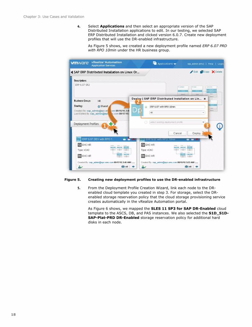
4. Select Applications and then select an appropriate version of the SAP Distributed Installation applications to edit. In our testing, we selected SAP
ERP Distributed Installation and clicked version 6.0.7. Create new deployment profiles that will use the DR-enabled infrastructure.
As Figure 5 shows, we created a new deployment profile named ERP 6.07 PRD with RPO 10min under the HR business group.
Figure 5. Creating new deployment profiles to use the DR-enabled infrastructure
5. From the Deployment Profile Creation Wizard, link each node to the DR-
enabled cloud template you created in step 3. For storage, select the DR-
enabled storage reservation policy that the cloud storage provisioning service
creates automatically in the vRealize Automation portal.
As Figure 6 shows, we mapped the SLES 11 SP3 for SAP DR-Enabled cloud
template to the ASCS, DB, and PAS instances. We also selected the S1D_S1D-
SAP-Plat-PRD DR-Enabled storage reservation policy for additional hard
disks in each node.

Chapter 3: Use Cases and Validation
19
Figure 6. Mapping cloud templates enabled for DR
6. Finish the wizard by assigning appropriate values for vCPUs, memory, and disk
size for each node.
7. Publish the deployment profile to the vRealize Automation portal.
8. Repeat steps 4 to 7 to create additional deployment profiles as necessary. For
example, you may need to provision SAP systems with different RPO
requirements.
9. Repeat steps 4 to 8 to configure SAP Standard Installation and SAP AAS
Installation.
10. Log in to the vRealize Automation portal as a tenant administrator. Assign the
published SAP provisioning applications to an appropriate service and assign
the required entitlements in the vRealize Automation portal.
From now on, the new SAP items are available in the service catalog, and the SAP system
with DR option requested by an end user is provisioned on the DR-enabled infrastructure.
This solution uses VMware vRealize Business, with its integration with vCenter and vRealize
Automation, to provide chargeback information on the storage provisioned to, and
consumed in, the hybrid cloud.
The ViPR storage provider running in vCenter automatically captures the underlying
capabilities of storage provisioned by ViPR. The storage administrator creates storage
profiles based on the storage capabilities of the ViPR storage, which is configured to provide
multiple storage service offerings. This integration enables vRealize Business to
automatically discover and group datastores based on predefined service levels of storage.
In this solution, we created separate virtual machine storage profiles for each of the storage
capabilities that were automatically captured by the ViPR storage provider, as Figure 7
shows.
Setting costs for
DR-enabled
storage

Chapter 3: Use Cases and Validation
20
Figure 7. Creating a virtual machine storage profile
After the ViPR storage provider has automatically configured the datastores with the
appropriate storage capability, these datastores can be grouped and managed in vRealize
Business according to their storage profile. As Figure 8 shows, the cost profiles created in
vCenter are discovered by vRealize Business.
Figure 8. Setting the cost for DR-enabled storage
The business management administrator can group tiered datastores provisioned with ViPR
and set the monthly cost per GB as needed to differentiate the cost of various storage
service levels. For example, to differentiate DR-enabled storages, we set the monthly cost
per GB of S1-DR-Silver DR-enabled storage to $0.4 to reflect the additional cost of
RecoverPoint and other hardware required to build the solution.

Chapter 3: Use Cases and Validation
21
In designing the use cases described in this section, our key business objectives were:
Operations: 24 hours a day, 7 days a week
RTO: 1 hour
RPO: As required for the relevant SAP system. Refer to Table 6 for details.
In the test environment, we1 configured six ESXi hosts for a tenant workload pod, three on
each DC. Table 5 shows the host details.
List of ESXi hosts Table 5.
DC ESXi hostnames
A S1vdccomp55, s1vdccomp56, s1vdccomp57
B s2vdccomp55, s2vdccomp56, s2vdccomp57
The two data centers were configured in accordance with the solution architecture shown in
Figure 1. We provisioned three 750GB DR-enabled storages with different RPOs for the HR
business group on Data Center A. We then deployed three distributed SAP ERP 6.07 systems
on those DR-enabled storages to build a typical three-system landscape with production
(PRD), development (DEV), and quality assurance (QAS).
Table 6 lists the RPO requirements for the provisioned SAP systems:
RPO requirements for SAP systems Table 6.
SAP system RPO (in minutes)
PRD 10
DEV 10
QAS 30
The RPO is defined in the ViPR virtual pool. Figure 9 shows the RPO setting for the virtual
pool in which we provisioned a datastore for the SAP PRD system.
Figure 9. RPO setting in the ViPR virtual pool
1 In this guide, “we” refers to the EMC engineering team that tested and validated the solution.

Chapter 3: Use Cases and Validation
22
When provisioning SAP systems from the vRealize Automation self-service portal, you can
specify the SRM Power On Priority for SAP instances so that ASCS is started first, followed
by DB, and finally PAS and AAS. Figure 10 shows the start priority for SAP instances.
Figure 10. Start priority for SAP instances
The workload generator T-code SGEN is used on all SAP systems to simulate workloads. To
measure RPO, we developed a customized program to generate one database record per
second on all SAP systems.
Note:
Benchmark results are highly dependent upon workload, specific application requirements, and
system design and implementation. Relative system performance will vary as a result of these
and other factors. Therefore, this workload should not be used as a substitute for a specific
customer application benchmark when critical capacity planning and/or product evaluation
decisions are contemplated.
All performance data contained in this report was obtained in a rigorously controlled
environment. Results obtained in other operating environments may vary significantly.
EMC Corporation does not warrant or represent that a user can or will achieve similar
performance expressed in transactions per minute.
Test scenario
A disaster occurred and resulted in a site outage at Data Center A. This outage could not be
recovered within the RTO in Data Center A. A failover to Data Center B was therefore
performed to bring services back online. To simulate this hardware failure scenario, we
powered off all the ESXi hosts and RPAs in Data Center A.
Objectives
All the SAP systems must be restored and back in service within the RTO and RPO.
Virtual machines such as DB, ASCS, PAS, and AAS within a SAP system must be started automatically after failover.
No errors should appear in the SAP systems.
Procedure
1. Run the workload generator (SGEN) on all SAP systems for at least 30 minutes.
2. Run the customized program to generate one record per second on all SAP systems.
3. Power off all ESXi servers of workload pods and RPAs in Data Center A.
Use case 1:
Failover after
disaster
Chapter 3: Use Cases and Validation
23
4. Log in to the vSphere web client in Data Center B and run the recovery operation.
Make a note of the failover procedure and timestamp.
5. After the failover, log in to the SAP systems and check the table to determine data
loss. Note the data loss time period.
6. Log in to all SAP systems using SAPGUI and check the transactions for errors,
including SICK, SM51, SM50, SM21, ST22, and DB02.
7. Log in to the PAS of all SAP systems and check the log file
/usr/sap/<SID>/DVEBMGS00/work/available.log to determine the duration of SAP
service unavailability.
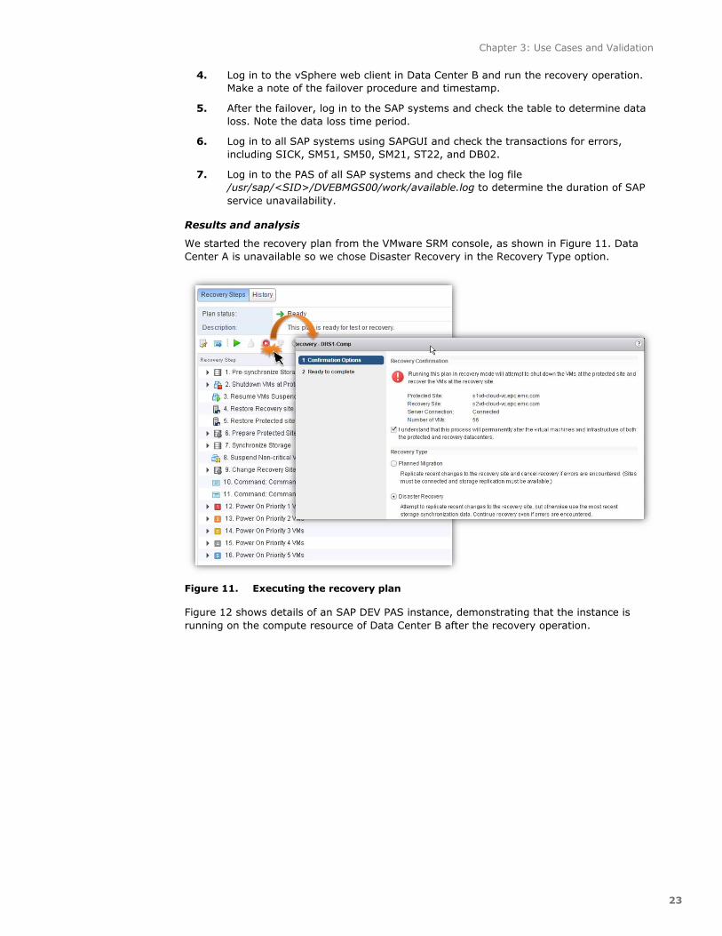
Results and analysis
We started the recovery plan from the VMware SRM console, as shown in Figure 11. Data
Center A is unavailable so we chose Disaster Recovery in the Recovery Type option.
Figure 11. Executing the recovery plan
Figure 12 shows details of an SAP DEV PAS instance, demonstrating that the instance is
running on the compute resource of Data Center B after the recovery operation.

Chapter 3: Use Cases and Validation
24
Figure 12. SAP instance running on Data Center B
Table 7 shows the observed behaviors of the system when the ESXi hosts failed, along with
the reference metrics in minutes.
Failover test results: Use case 1 Table 7.
Test item Success criterion Results
PRD RTO (minutes) <= 60 20
DEV RTO (minutes) <= 60 20
QAS RTO (minutes) <= 60 20
PRD RPO (minutes) <= 10 2
DEV RPO (minutes) <= 10 2
QAS RPO (minutes) <= 30 13
Autostart of SAP instances
SAP instances are started in the correct order. Autostart scripts are executed along with the OS boot. SAP systems are started automatically.
Success
Errors in the SAP systems
0 0
Final evaluation PASSED
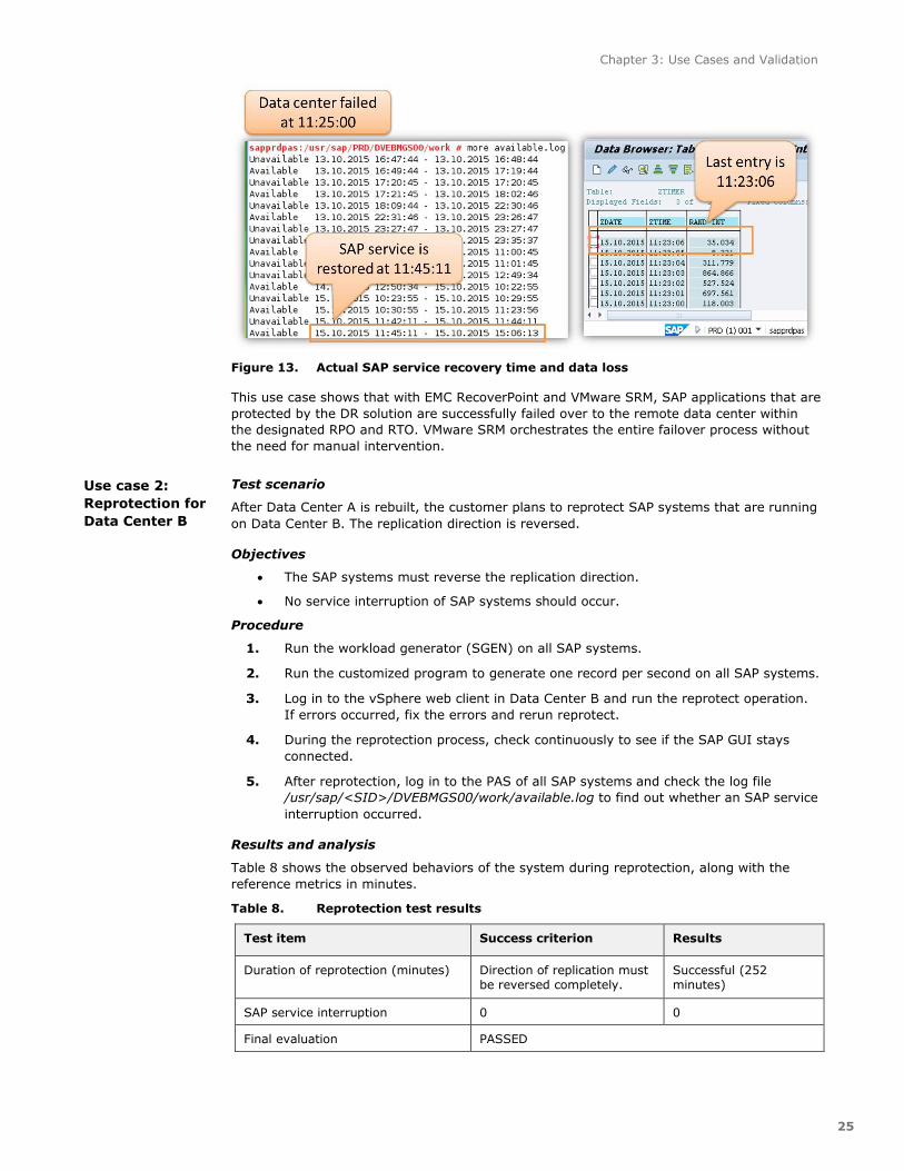
The simulated disaster was triggered at 11:25:00. Figure 13 shows the actual recovery time
and data loss of the SAP PRD system.
Chapter 3: Use Cases and Validation
25
Figure 13. Actual SAP service recovery time and data loss
This use case shows that with EMC RecoverPoint and VMware SRM, SAP applications that are
protected by the DR solution are successfully failed over to the remote data center within
the designated RPO and RTO. VMware SRM orchestrates the entire failover process without
the need for manual intervention.
Test scenario
After Data Center A is rebuilt, the customer plans to reprotect SAP systems that are running
on Data Center B. The replication direction is reversed.
Objectives
The SAP systems must reverse the replication direction.
No service interruption of SAP systems should occur.
Procedure
1. Run the workload generator (SGEN) on all SAP systems.
2. Run the customized program to generate one record per second on all SAP systems.
3. Log in to the vSphere web client in Data Center B and run the reprotect operation.
If errors occurred, fix the errors and rerun reprotect.
4. During the reprotection process, check continuously to see if the SAP GUI stays
connected.
5. After reprotection, log in to the PAS of all SAP systems and check the log file
/usr/sap/<SID>/DVEBMGS00/work/available.log to find out whether an SAP service
interruption occurred.
Results and analysis
Table 8 shows the observed behaviors of the system during reprotection, along with the
reference metrics in minutes.
Reprotection test results Table 8.
Test item Success criterion Results
Duration of reprotection (minutes) Direction of replication must
be reversed completely.
Successful (252
minutes)
SAP service interruption 0 0
Final evaluation PASSED
Use case 2:
Reprotection for
Data Center B

Chapter 3: Use Cases and Validation
26
A full initial replication is triggered on RPA. The total duration of reprotection depends on the
total capacity of the volumes in the consistency groups and the WAN bandwidth between
two DCs.
Test scenario
After Data Center B is reprotected, the customer plans to migrate SAP applications from
Data Center B back to Data Center A to balance resource usage. A planned downtime is
required.
Objectives
All the SAP systems must be migrated and back in service within the RTO. The RPO must be zero.
Virtual machines within an SAP system, such as DB, ASCS, PAS, and AAS, must be started automatically after failover.
No errors should appear in the SAP systems.
Procedure
1. Note the latest entries in the database table for all SAP systems, and then shut
down all SAP systems.
2. Log in to the vSphere web client in Data Center A and run the planned migration
operation. Note the migration procedure and timestamp.
3. After the planned migration, log in to the SAP system using the SAP GUI and check
the transactions for any errors, including SICK, SM51, SM50, SM21, ST22, and
DB02.
4. Check the latest entries for all SAP systems in the database table to determine data
loss.
5. Log in to the PAS of all SAP systems and check the log file
/usr/sap/<SID>/DVEBMGS00/work/available.log to determine the duration of SAP
service unavailability.
Results and analysis
We started the recovery plan from the VMware SRM console. In the Recovery Type option,
we chose Planned migration so that VMware SRM would gracefully shut down SAP systems
before migration.
Table 9 shows the observed behaviors of the system during planned migration, along with
reference metrics in minutes.
Planned migration test results Table 9.
Test item Success criterion Results
PRD RTO (minutes) <= 60 21
DEV RTO (minutes) <= 60 20
QAS RTO (minutes) <= 60 21
PRD RPO (minutes) 0 0
DEV RPO (minutes) 0 0
QAS RPO (minutes) 0 0
Use case 3:
Planned
migration

Chapter 3: Use Cases and Validation
27
Test item Success criterion Results
Auto start of SAP instances
SAP instances are started in the correct order.
Autostart scripts are executed along with the operating system boot.
SAP systems are started automatically.
Success
Errors in the SAP systems
0 0
Final evaluation PASSED
Figure 14 shows the database record of three SAP systems before and after planned
migration, indicating no data loss.
Figure 14. Actual recovery time and data loss
This use case shows that with RecoverPoint and SRM, SAP applications that are protected by
the DR solution are successfully migrated to the remote data center within the designated
RTO and with no data loss.
Test scenario
After Data Center A is rebuilt, the customer plans to reprotect SAP systems that are running
on Data Center B. The replication direction is reversed.
Use case 4:
Reprotection for
Data Center A

Chapter 3: Use Cases and Validation
28
Objectives and procedure
The test objectives and procedure are the same as in Use case 2: Reprotection for Data Center B.
Results and analysis
Table 10 shows the observed behaviors of the system during reprotection, along with
reference metrics in minutes.
Reprotection test results for Data Center A Table 10.
Test item Success criterion Results
Duration of reprotection
(minutes)
Direction of replication must be
reversed completely
Successful (4 minutes)
SAP Service interruption 0 0
Final evaluation PASSED
Test scenario
To ensure a successful failover after a real disaster, the customer must validate the recovery
plan without interrupting the running SAP systems.
Objectives
The recovery plan is executed successfully in test mode.
The SAP virtual machines are powered on at the remote data center with the network isolated.
The running SAP systems are not affected.
Procedure
1. Log in to the vSphere web client in Data Center A and run the recovery plan in test
mode. Note the test recovery procedure and timestamp.
2. Check whether the SAP virtual machines are powered on at the remote data center.
3. Check whether the network of SAP virtual machines is isolated.
Results and analysis
We started the recovery plan in test mode from the VMware SRM console. After successful
execution of the recovery plan, the replicated datastores were mounted on the ESXi hosts at
the remote DC and the SAP virtual machines were powered on. During the test, the running
SAP systems at the production data center were not affected. Figure 15 shows that the
networks of SAP virtual machines in test recovery are isolated.
Use case 5: Test
recovery

Chapter 3: Use Cases and Validation
29
Figure 15. Isolated network of SAP virtual machines in test recovery
This use case demonstrates that with the test recovery, customers can perform periodic
validation of a recovery plan without incurring a huge cost or disruption to the business.
Chapter 4: Conclusion
30
This chapter presents the following topics:
Conclusion ........................................................................................................ 31
Chapter 4: Conclusion
31
This solution offers effective, efficient, and affordable DR protection for critical business
functions. This strategy significantly improves business agility and scales out for SAP
production systems with varying needs.
The Federation Enterprise Hybrid Cloud for SAP integrates the best of EMC and VMware
products and enables customers to protect SAP system landscapes from disasters such as
the outage of an entire Data Center. With the integration of ViPR, vCenter Orchestrator, and
vRealize Automation, cloud administrators can request DR-enabled storage through the
vRealize Automation self-service portal and end users can provision SAP systems on DR-
enabled infrastructures with just a few clicks. With the integration of RecoverPoint and
vCenter Site Recovery Manager, the DR processes are automated and orchestrated in their
entirety with just a few clicks.
The solution provides the following protection benefits for SAP systems:
Business continuity for mission-critical SAP applications in a cloud environment.
Cloud tenants have the option to easily deploy their most critical SAP systems on the
DR infrastructures described in this solution. The DR costs are captured in the
chargeback report. The failover and failback processes do not require additional
intervention from the tenants.
Rapid and automated DR in a cloud environment.
The DR administrator can easily complete the entire DR process with a few clicks. This
is critical to ensuring RTO in a large-scale cloud environment.

Appendix A: References
32
This appendix presents the following topics:
References ........................................................................................................ 33

Appendix A: References
33
The following documents are available on EMC.com or EMC Online Support. Access to online
support depends on your login credentials. If you do not have access to a document, contact
your Federation representative.
Federation Enterprise Hybrid Cloud 3.1: Foundation Infrastructure Reference
Architecture Guide
Federation Enterprise Hybrid Cloud 3.1: Concepts and Architecture Solution Guide
Federation Enterprise Hybrid Cloud 3.1: Operations Solution Guide
Federation Enterprise Hybrid Cloud 3.1: Security Management Solution Guide
Federation Enterprise Hybrid Cloud 3.1: Foundation for SAP Solution Guide
EMC Cloud-Enabled Infrastructure for SAP: HA and Application Mobility Bundle
RecoverPoint 4.1 Administrator's Guide
The following document is available from www.vmware.com.
Site Recovery Manager Administration: vCenter Site Recovery Manager 5.8
EMC
documentation
Other product
documentation