Embed Size (px)
Citation preview
FEDERATION CYNOLOGIQUE INTERNATIONALE (AISBL) Place Albert 1
er, 13 – B – 6530 Thuin, tel : +32.71.59.12.38, fax : +32.71.59.22.29, internet : http://www.fci.be
AGILITY OBSTACLE GUIDELINES
January 1 2018
Agility Obstacle Guidelines 2
TABLE OF CONTENTS
1. Introduction .............................................................................................................................. 3
2. Obstacle safety ........................................................................................................................ 4
3. Tolerances ............................................................................................................................... 4
4. Specific Obstacles .................................................................................................................... 5
4.1 Hurdles ............................................................................................................................... 5
4.1.1 Drawings and rules ...................................................................................................... 5
4.1.2 Specifications for construction ...................................................................................... 6
4.2 Wall/Viaduct........................................................................................................................ 8
4.2.1 Drawing and rules ........................................................................................................ 8
4.2.2 Specifications for construction ...................................................................................... 8
4.3 Tyre .................................................................................................................................... 8
4.3.1 Drawings and rules ...................................................................................................... 8
4.3.2 Specifications for construction .................................................................................... 10
4.4 Long jump ......................................................................................................................... 11
4.4.1 Drawing and rules ...................................................................................................... 11
4.4.2 Specifications for construction .................................................................................... 12
4.5 Contact obstacles ............................................................................................................. 12
4.5.1 Drawings and rules .................................................................................................... 12
4.5.2 Specifications for construction .................................................................................... 14
4.6 Flat tunnel ......................................................................................................................... 15
4.6.1 Drawing and rules ...................................................................................................... 15
4.6.2 Specifications for construction .................................................................................... 15
4.7 Tube tunnel ...................................................................................................................... 16
4.7.1 Drawing and rules ...................................................................................................... 16
4.7.2 Specifications for construction .................................................................................... 16
4.8 Weave poles ..................................................................................................................... 17
4.8.1 Drawing and rules ...................................................................................................... 17
4.8.2 Specifications for construction .................................................................................... 17
Agility Obstacle Guidelines 3
1. Introduction
These “Obstacle Guidelines” are meant to help people in FCI member countries, who work with Agility obstacles, to come to the same understanding and interpretation of the rules.
The Guidelines do not intend to change existing rules or to be in contradiction with them, but they should help to clarify the gaps in interpretation left by the wording and/or drawings in the rules. The application of these Guidelines is compulsory at FCI events such as the World Championships, the European Open, the Junior Agility European Open and CACIAg competitions.
The English text of these Guidelines in the latest version is always the reference one. Different interpretations can be caused by the translation into different languages.
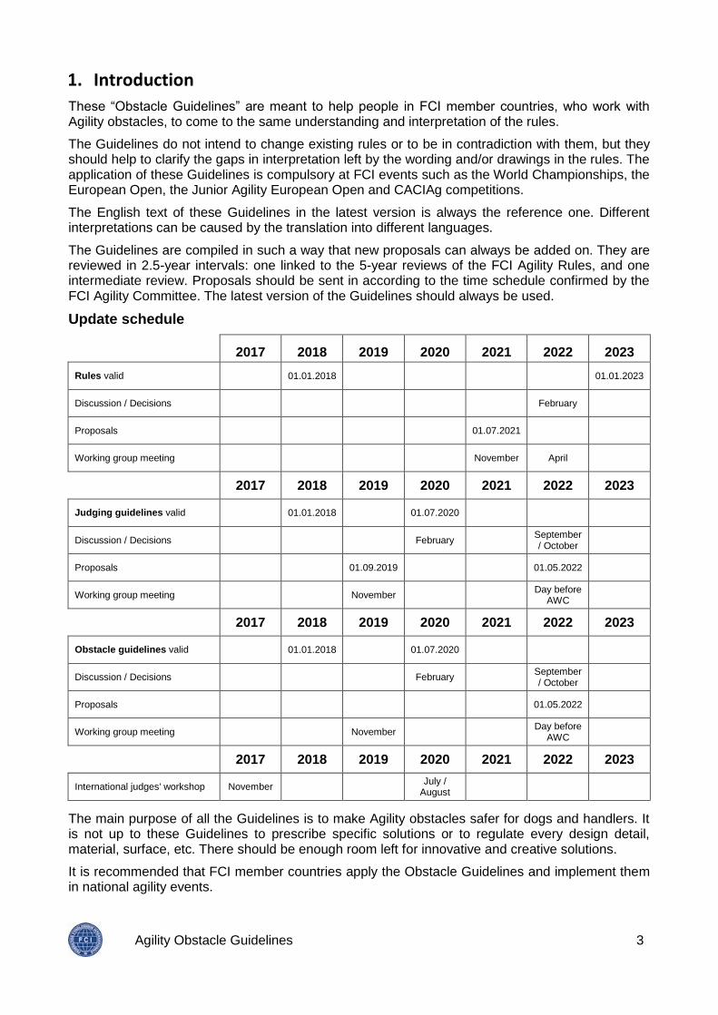
The Guidelines are compiled in such a way that new proposals can always be added on. They are reviewed in 2.5-year intervals: one linked to the 5-year reviews of the FCI Agility Rules, and one intermediate review. Proposals should be sent in according to the time schedule confirmed by the FCI Agility Committee. The latest version of the Guidelines should always be used.
Update schedule
2017 2018 2019 2020 2021 2022 2023
Rules valid 01.01.2018 01.01.2023
Discussion / Decisions February
Proposals 01.07.2021
Working group meeting November April
2017 2018 2019 2020 2021 2022 2023
Judging guidelines valid 01.01.2018 01.07.2020
Discussion / Decisions February September / October
Proposals 01.09.2019 01.05.2022
Working group meeting November Day before
AWC
2017 2018 2019 2020 2021 2022 2023
Obstacle guidelines valid 01.01.2018 01.07.2020
Discussion / Decisions February September / October
Proposals 01.05.2022
Working group meeting November Day before
AWC
2017 2018 2019 2020 2021 2022 2023
International judges' workshop November July /
August
The main purpose of all the Guidelines is to make Agility obstacles safer for dogs and handlers. It is not up to these Guidelines to prescribe specific solutions or to regulate every design detail, material, surface, etc. There should be enough room left for innovative and creative solutions.
It is recommended that FCI member countries apply the Obstacle Guidelines and implement them in national agility events.
Agility Obstacle Guidelines 4
2. Obstacle safety
Ultimate responsibility for the welfare and safety of the dog lies always with the owner/handler. The risk of accidents and injuries can only be reduced, but never completely eliminated.
Obstacles should not only be safe for dogs and handlers, but also for everyone else that has to work with or handle them (assembling, course-building, transportation, storage, etc.).
Agility obstacles should be useable under the various external conditions (temperature, wind, rain, mud, snow, ice, etc.) for which they have been designed.
No part of any obstacle should be dangerous for a dog, even when it goes underneath it, past it or through it. When hollow metal profiles are used, all holes should be closed (covered). Furthermore, there should not be any protruding parts on which the dog could get caught or stuck.
3. Tolerances
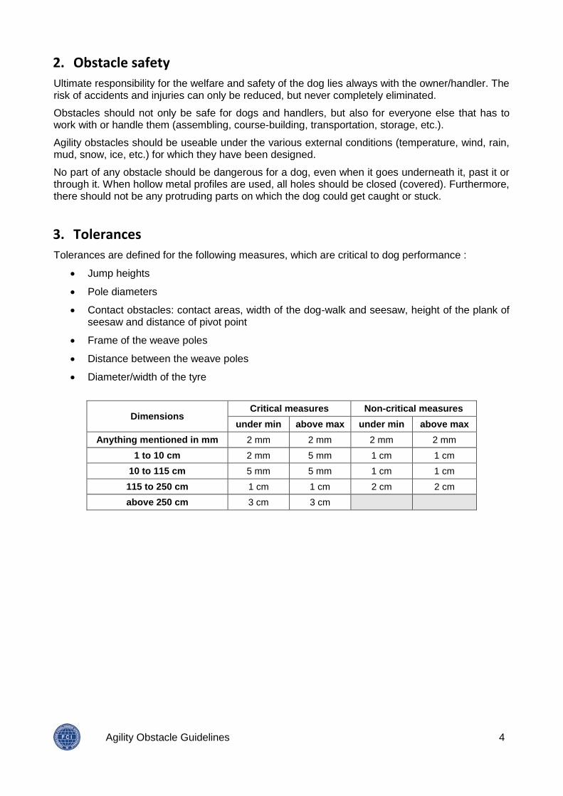
Tolerances are defined for the following measures, which are critical to dog performance :
Jump heights
Pole diameters
Contact obstacles: contact areas, width of the dog-walk and seesaw, height of the plank of seesaw and distance of pivot point
Frame of the weave poles
Distance between the weave poles
Diameter/width of the tyre
Dimensions Critical measures Non-critical measures
under min above max under min above max
Anything mentioned in mm 2 mm 2 mm 2 mm 2 mm
1 to 10 cm 2 mm 5 mm 1 cm 1 cm
10 to 115 cm 5 mm 5 mm 1 cm 1 cm
115 to 250 cm 1 cm 1 cm 2 cm 2 cm
above 250 cm 3 cm 3 cm
Agility Obstacle Guidelines 5
4. Specific Obstacles
4.1 Hurdles
4.1.1 Drawings and rules
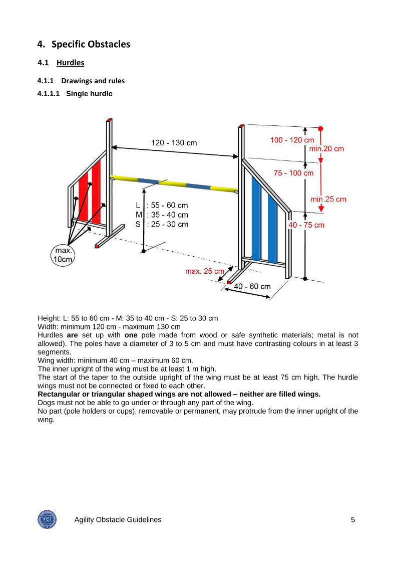
4.1.1.1 Single hurdle
Height: L: 55 to 60 cm - M: 35 to 40 cm - S: 25 to 30 cm Width: minimum 120 cm - maximum 130 cm Hurdles are set up with one pole made from wood or safe synthetic materials; metal is not allowed). The poles have a diameter of 3 to 5 cm and must have contrasting colours in at least 3 segments. Wing width: minimum 40 cm – maximum 60 cm. The inner upright of the wing must be at least 1 m high. The start of the taper to the outside upright of the wing must be at least 75 cm high. The hurdle wings must not be connected or fixed to each other. Rectangular or triangular shaped wings are not allowed – neither are filled wings. Dogs must not be able to go under or through any part of the wing. No part (pole holders or cups), removable or permanent, may protrude from the inner upright of the wing.
Agility Obstacle Guidelines 6
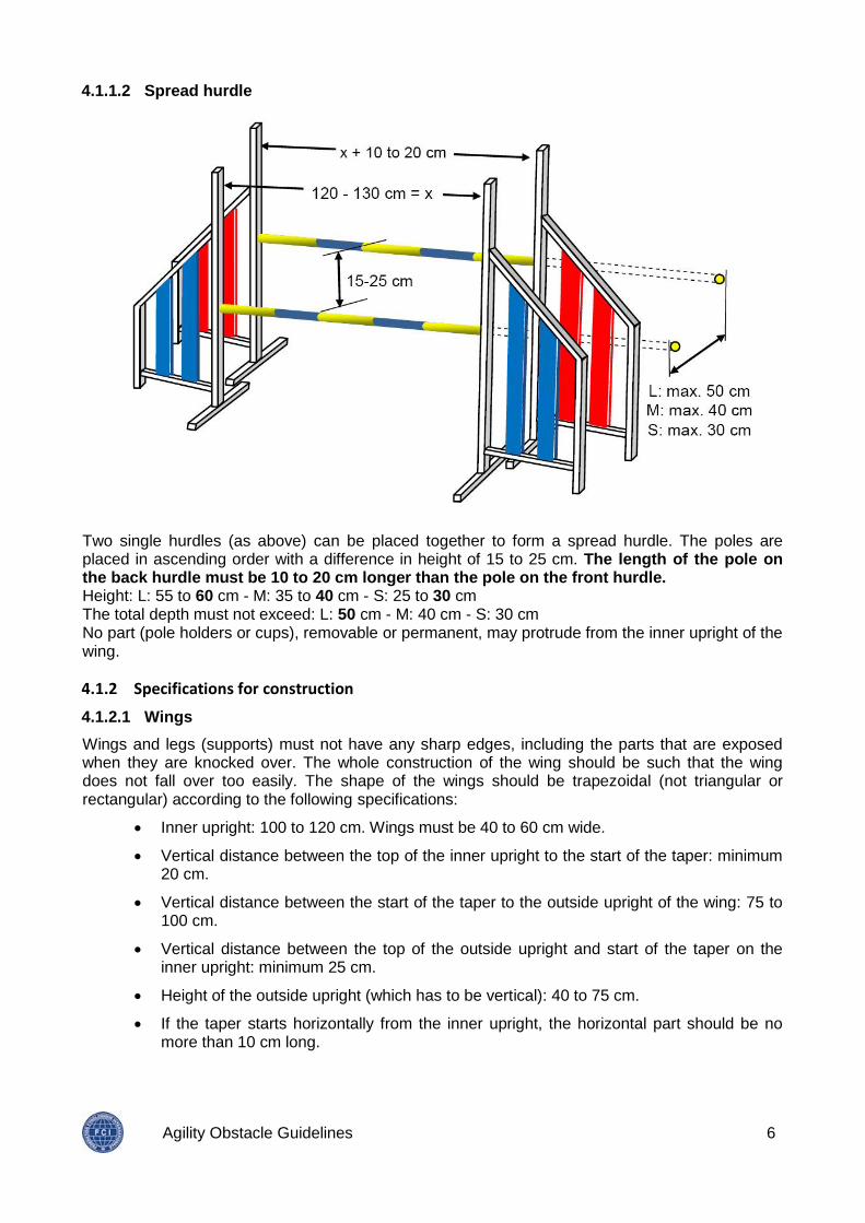
4.1.1.2 Spread hurdle
Two single hurdles (as above) can be placed together to form a spread hurdle. The poles are placed in ascending order with a difference in height of 15 to 25 cm. The length of the pole on the back hurdle must be 10 to 20 cm longer than the pole on the front hurdle. Height: L: 55 to 60 cm - M: 35 to 40 cm - S: 25 to 30 cm The total depth must not exceed: L: 50 cm - M: 40 cm - S: 30 cm No part (pole holders or cups), removable or permanent, may protrude from the inner upright of the wing.
4.1.2 Specifications for construction
4.1.2.1 Wings
Wings and legs (supports) must not have any sharp edges, including the parts that are exposed when they are knocked over. The whole construction of the wing should be such that the wing does not fall over too easily. The shape of the wings should be trapezoidal (not triangular or rectangular) according to the following specifications:
Inner upright: 100 to 120 cm. Wings must be 40 to 60 cm wide.
Vertical distance between the top of the inner upright to the start of the taper: minimum 20 cm.
Vertical distance between the start of the taper to the outside upright of the wing: 75 to 100 cm.
Vertical distance between the top of the outside upright and start of the taper on the inner upright: minimum 25 cm.
Height of the outside upright (which has to be vertical): 40 to 75 cm.
If the taper starts horizontally from the inner upright, the horizontal part should be no more than 10 cm long.

Agility Obstacle Guidelines 7
The gap underneath the wing and between the slats in the frame of the wing should be between 5 and 10 cm. The slats must be wider than the gaps between them
Corners of the trapezoid can be rounded. Horizontal parts/slats in the wing should be avoided.
The leg on each side of the inner upright should be long enough to ensure stability of the wing, but not more than 25 cm. The width of the legs should be 3-5 cm. The height of the legs should be as low as possible consistent with mechanical stability, e.g., 3 cm for metal legs. If the legs are made from wood, they may be up to 15 cm high, but at most 20 cm long. In this case, an additional wooden leg, maximum 10 cm long, may be added on the base of outer upright.
It must be possible to fit pole holders to the wing to ensure jump heights of 10, 15, 20, 25, 30, 35, 40, 45, 50, 55 and 60 cm.
4.1.2.2 Poles/Bars
Poles must be round (no rectangular poles) with a diameter of 3 to 5 cm.
The poles must have a smooth surface. Plastic poles must be made of thick walled, non-splintering, UV-resistant and temperature-resistant synthetic material. The contrast between the colours must be easily recognizable for the dogs (e.g., contrast between a light and a dark colour is more visible to dogs than two colours in the middle of the colour scale).
Filled panels are not allowed.
4.1.2.3 Pole holders
Pole holders should fit onto the upright in such a way that there is no residual movement greater than 2 mm. The connection between pole holder and upright of the wing should be firm enough so that the pole holder itself does not drop each time a pole is knocked down.
Pole holders may be curved or V-shaped (no horizontal pole holders). They should hold the poles correctly, even when the temperature changes, in such a way that all dogs are able to knock down the pole, but firmly enough so that the pole does not fall due to:
a slight wind
a mere touch
vibrations of a wooden floor in a hall, caused by a running handler a shifting carpet, etc.
The best compromise between the two extreme situations of flat holders (which don't hold the pole at all) and semi-circular pole holders (which hold the pole too firmly) is given by the following dimensions relative to the pole diameter:
Agility Obstacle Guidelines 8
4.2 Wall/Viaduct
4.2.1 Drawing and rules
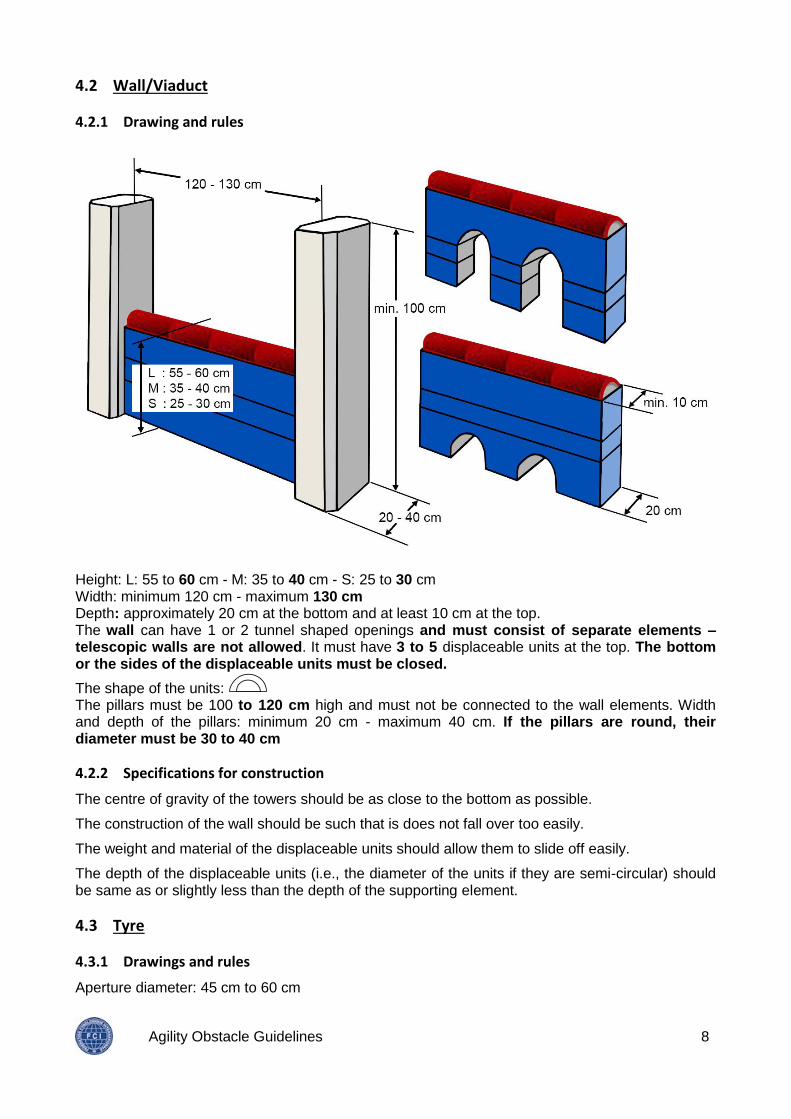
Height: L: 55 to 60 cm - M: 35 to 40 cm - S: 25 to 30 cm Width: minimum 120 cm - maximum 130 cm Depth: approximately 20 cm at the bottom and at least 10 cm at the top. The wall can have 1 or 2 tunnel shaped openings and must consist of separate elements – telescopic walls are not allowed. It must have 3 to 5 displaceable units at the top. The bottom or the sides of the displaceable units must be closed.
The shape of the units: The pillars must be 100 to 120 cm high and must not be connected to the wall elements. Width and depth of the pillars: minimum 20 cm - maximum 40 cm. If the pillars are round, their diameter must be 30 to 40 cm
4.2.2 Specifications for construction
The centre of gravity of the towers should be as close to the bottom as possible.
The construction of the wall should be such that is does not fall over too easily.
The weight and material of the displaceable units should allow them to slide off easily.
The depth of the displaceable units (i.e., the diameter of the units if they are semi-circular) should be same as or slightly less than the depth of the supporting element.
4.3 Tyre
4.3.1 Drawings and rules
Aperture diameter: 45 cm to 60 cm
Agility Obstacle Guidelines 9
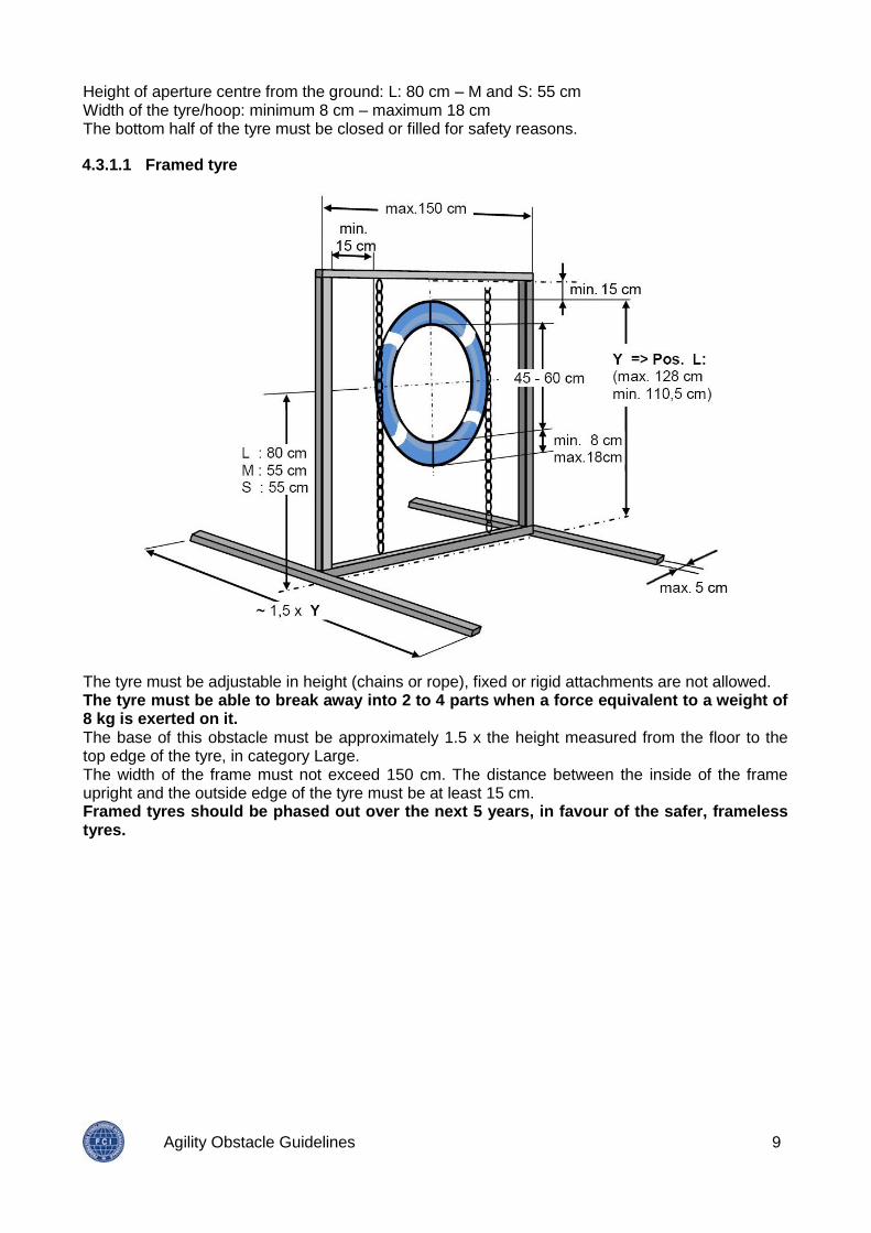
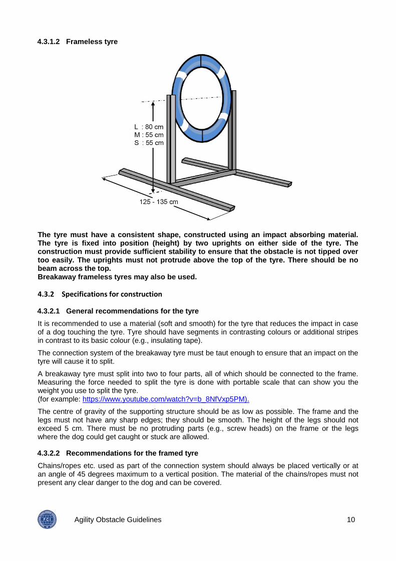
Height of aperture centre from the ground: L: 80 cm – M and S: 55 cm Width of the tyre/hoop: minimum 8 cm – maximum 18 cm The bottom half of the tyre must be closed or filled for safety reasons.
4.3.1.1 Framed tyre
The tyre must be adjustable in height (chains or rope), fixed or rigid attachments are not allowed. The tyre must be able to break away into 2 to 4 parts when a force equivalent to a weight of 8 kg is exerted on it. The base of this obstacle must be approximately 1.5 x the height measured from the floor to the top edge of the tyre, in category Large. The width of the frame must not exceed 150 cm. The distance between the inside of the frame upright and the outside edge of the tyre must be at least 15 cm. Framed tyres should be phased out over the next 5 years, in favour of the safer, frameless tyres.
Agility Obstacle Guidelines 10
4.3.1.2 Frameless tyre
The tyre must have a consistent shape, constructed using an impact absorbing material. The tyre is fixed into position (height) by two uprights on either side of the tyre. The construction must provide sufficient stability to ensure that the obstacle is not tipped over too easily. The uprights must not protrude above the top of the tyre. There should be no beam across the top. Breakaway frameless tyres may also be used.
4.3.2 Specifications for construction
4.3.2.1 General recommendations for the tyre
It is recommended to use a material (soft and smooth) for the tyre that reduces the impact in case of a dog touching the tyre. Tyre should have segments in contrasting colours or additional stripes in contrast to its basic colour (e.g., insulating tape).
The connection system of the breakaway tyre must be taut enough to ensure that an impact on the tyre will cause it to split.
A breakaway tyre must split into two to four parts, all of which should be connected to the frame. Measuring the force needed to split the tyre is done with portable scale that can show you the weight you use to split the tyre. (for example: https://www.youtube.com/watch?v=b_8NfVxp5PM).
The centre of gravity of the supporting structure should be as low as possible. The frame and the legs must not have any sharp edges; they should be smooth. The height of the legs should not exceed 5 cm. There must be no protruding parts (e.g., screw heads) on the frame or the legs where the dog could get caught or stuck are allowed.
4.3.2.2 Recommendations for the framed tyre
Chains/ropes etc. used as part of the connection system should always be placed vertically or at an angle of 45 degrees maximum to a vertical position. The material of the chains/ropes must not present any clear danger to the dog and can be covered.
Agility Obstacle Guidelines 11
4.3.2.3 Recommendations for the frameless tyre
The structure of the uprights and legs must be stable and safe, especially the upper parts of the uprights when the tyre is set up for small or medium dogs.
Connection of the tyre to the uprights must be rigid.
4.3.2.4 Recommendations for a non-breakable tyre if used in national competition
The material on the inner side of the tyre should be smooth, so that if the dog happens to touch it, it will just slide through.
The frame of non-breakable tyre must not be too heavy. The connection system of the tyre with the frame should be adjusted so that the impact on a dog that hits the tyre is not so intensive.
4.4 Long jump
4.4.1 Drawing and rules
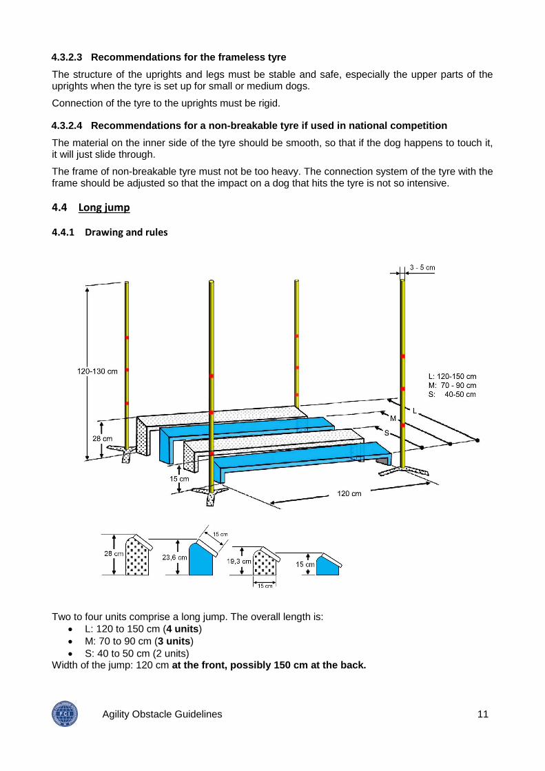
Two to four units comprise a long jump. The overall length is:
L: 120 to 150 cm (4 units)
M: 70 to 90 cm (3 units)
S: 40 to 50 cm (2 units) Width of the jump: 120 cm at the front, possibly 150 cm at the back.
Agility Obstacle Guidelines 12
The units are placed in ascending order. Height of the lowest unit: 15 cm. Height of the highest unit: 28 cm. Depth of each unit: 15 cm, rising in height. The angle of inclination of the units must be such that the front edge of each unit is no higher than the back edge of the previous unit. All the planks (but not necessarily the feet) of the long jump must be made of wood or safe synthetic material (metal not allowed). Corner poles, height 120 to 130 cm – diameter 3-5 cm, must be placed at all four corners (not fixed to any of the units). The top of these poles should be covered to protect dog and handler if necessary. The marker poles are not considered to be part of the obstacle; they are only a judging aid.
4.4.2 Specifications for construction
The surface of the units should be non-reflective. Contrasting colours in the units are recommended.
The diameter of the marker poles should be 3-5 cm. The legs and the top of the marker poles should not present any obvious danger, even when the marker poles are knocked down. The marker poles should have segments in contrasting colours or additional stripes in a contrasting colour.
4.5 Contact obstacles
4.5.1 Drawings and rules
4.5.1.1 Dog-walk
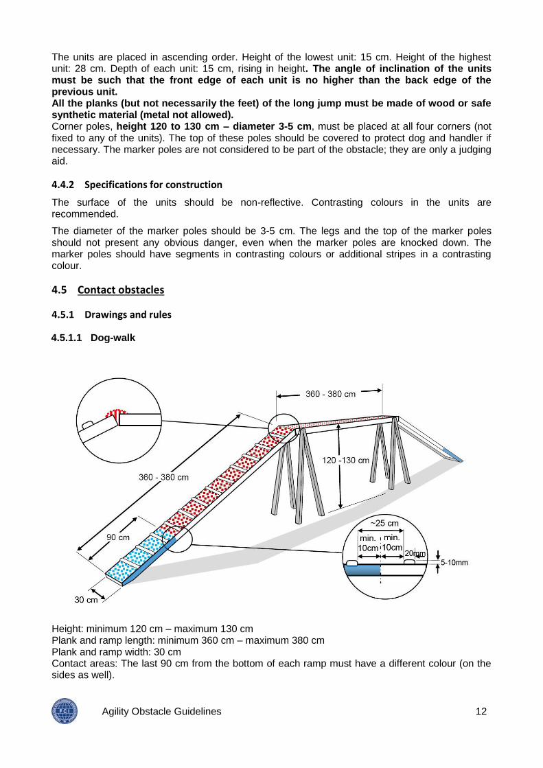
Height: minimum 120 cm – maximum 130 cm Plank and ramp length: minimum 360 cm – maximum 380 cm Plank and ramp width: 30 cm Contact areas: The last 90 cm from the bottom of each ramp must have a different colour (on the sides as well).
Agility Obstacle Guidelines 13
The surface of the obstacle must be non-slip. Each ramp must have anti-slip slats at regular intervals (about every 25 cm) to avoid slipping and making the climb easier, but not within 10 cm of the start of a contact area. These slats must be 2 cm wide and 0.5 to 1 cm thick, and must not have sharp edges. The bottom of the contact zone must be filled (no gaps) and not flattened too much (no sharp edges). The legs of the dog walk must not protrude above the top of the obstacle. The legs and other supporting structures must not prevent the tunnel from being placed safely under the dog-walk.
4.5.1.2 See-saw
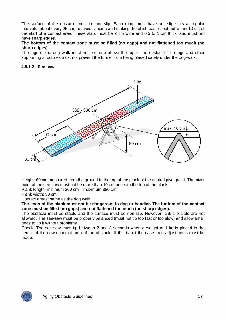
Height: 60 cm measured from the ground to the top of the plank at the central pivot point. The pivot point of the see-saw must not be more than 10 cm beneath the top of the plank. Plank length: minimum 360 cm – maximum 380 cm Plank width: 30 cm Contact areas: same as the dog walk. The ends of the plank must not be dangerous to dog or handler. The bottom of the contact zone must be filled (no gaps) and not flattened too much (no sharp edges). The obstacle must be stable and the surface must be non-slip. However, anti-slip slats are not allowed. The see-saw must be properly balanced (must not tip too fast or too slow) and allow small dogs to tip it without problems. Check: The see-saw must tip between 2 and 3 seconds when a weight of 1 kg is placed in the centre of the down contact area of the obstacle. If this is not the case then adjustments must be made.
Agility Obstacle Guidelines 14
4.5.1.3 A-frame
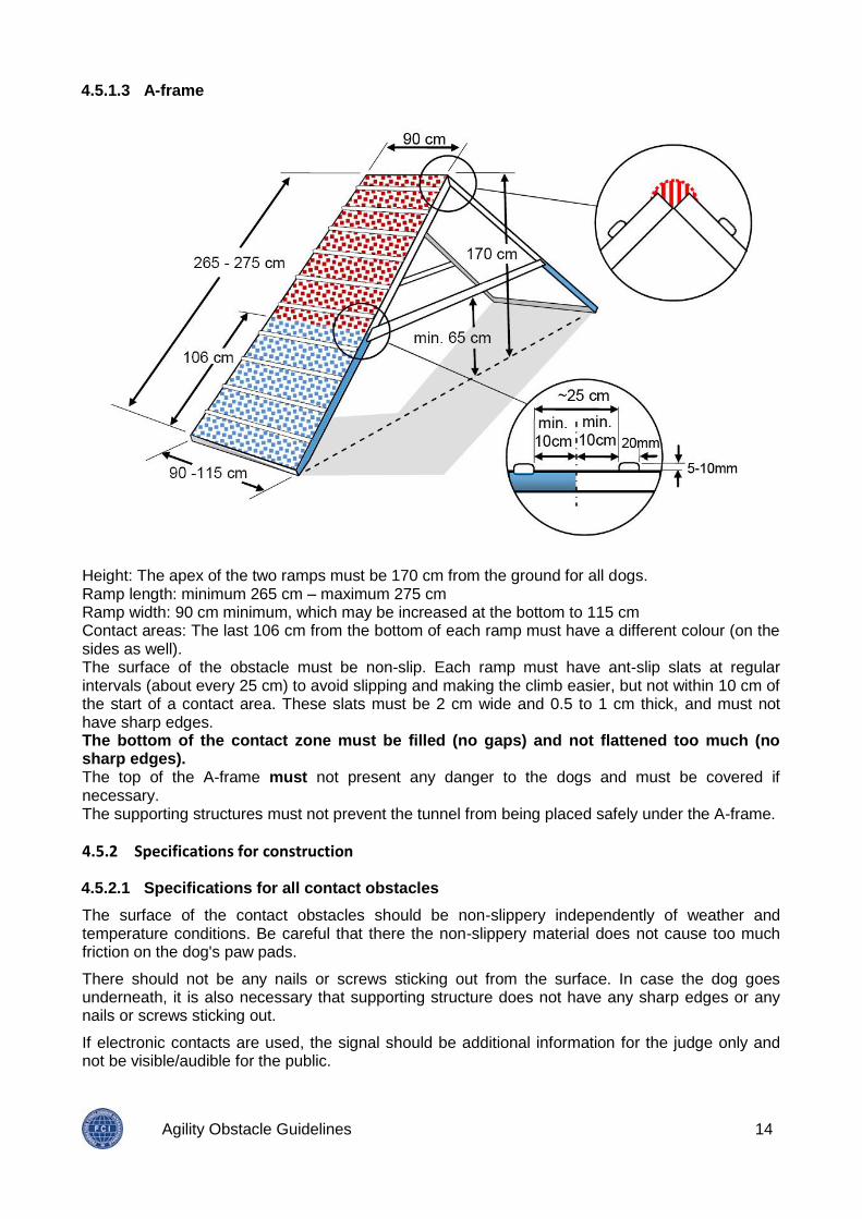
Height: The apex of the two ramps must be 170 cm from the ground for all dogs. Ramp length: minimum 265 cm – maximum 275 cm Ramp width: 90 cm minimum, which may be increased at the bottom to 115 cm Contact areas: The last 106 cm from the bottom of each ramp must have a different colour (on the sides as well). The surface of the obstacle must be non-slip. Each ramp must have ant-slip slats at regular intervals (about every 25 cm) to avoid slipping and making the climb easier, but not within 10 cm of the start of a contact area. These slats must be 2 cm wide and 0.5 to 1 cm thick, and must not have sharp edges. The bottom of the contact zone must be filled (no gaps) and not flattened too much (no sharp edges). The top of the A-frame must not present any danger to the dogs and must be covered if necessary. The supporting structures must not prevent the tunnel from being placed safely under the A-frame.
4.5.2 Specifications for construction
4.5.2.1 Specifications for all contact obstacles
The surface of the contact obstacles should be non-slippery independently of weather and temperature conditions. Be careful that there the non-slippery material does not cause too much friction on the dog's paw pads.
There should not be any nails or screws sticking out from the surface. In case the dog goes underneath, it is also necessary that supporting structure does not have any sharp edges or any nails or screws sticking out.
If electronic contacts are used, the signal should be additional information for the judge only and not be visible/audible for the public.
Agility Obstacle Guidelines 15
4.5.2.2 Special specifications
Dog-walk
The up and down ramps must be securely connected to the horizontal plank without any gaps.
The up and down ramps can be stabilized by an additional support if necessary.
See-saw
The material used for the see-saw must make the plank rigid enough to avoid any bending.
A-frame
The supporting structures connecting the two ramps must be positioned high enough to allow a tunnel to be placed safely under the A-frame and not to present a potential danger to dogs running underneath the obstacle.
There should be no gaps at the apex of the A-frame.
4.6 Flat tunnel
4.6.1 Drawing and rules
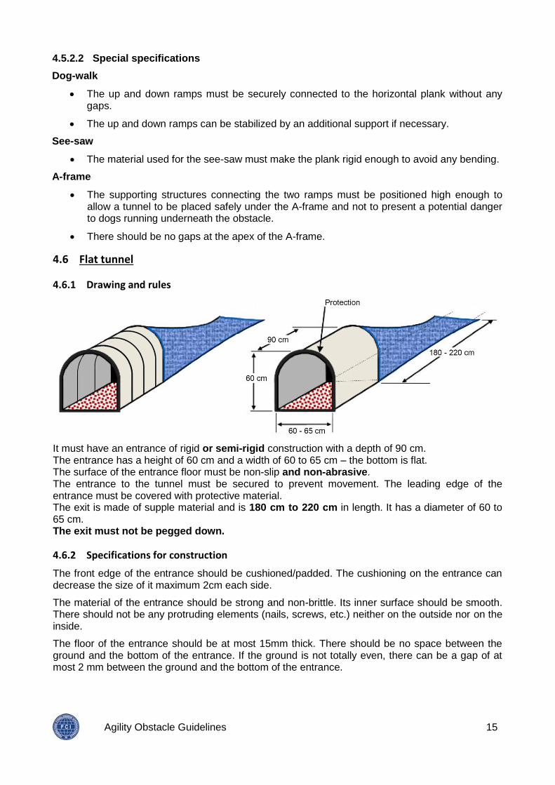
It must have an entrance of rigid or semi-rigid construction with a depth of 90 cm. The entrance has a height of 60 cm and a width of 60 to 65 cm – the bottom is flat. The surface of the entrance floor must be non-slip and non-abrasive. The entrance to the tunnel must be secured to prevent movement. The leading edge of the entrance must be covered with protective material. The exit is made of supple material and is 180 cm to 220 cm in length. It has a diameter of 60 to 65 cm. The exit must not be pegged down.
4.6.2 Specifications for construction
The front edge of the entrance should be cushioned/padded. The cushioning on the entrance can decrease the size of it maximum 2cm each side.
The material of the entrance should be strong and non-brittle. Its inner surface should be smooth. There should not be any protruding elements (nails, screws, etc.) neither on the outside nor on the inside.
The floor of the entrance should be at most 15mm thick. There should be no space between the ground and the bottom of the entrance. If the ground is not totally even, there can be a gap of at most 2 mm between the ground and the bottom of the entrance.
Agility Obstacle Guidelines 16
The material used for the exit/flat part of the tunnel has to be light and such that the top and bottom parts do not stick together. The bottom part should ideally be heavier than the top part; this can be achieved by using different materials. Light colours are recommended.
The entrance must be fixed in place (e.g., with sandbags) to prevent any movement. If the entrance is pegged down, then be aware for protruding material.
4.7 Tube tunnel
4.7.1 Drawing and rules
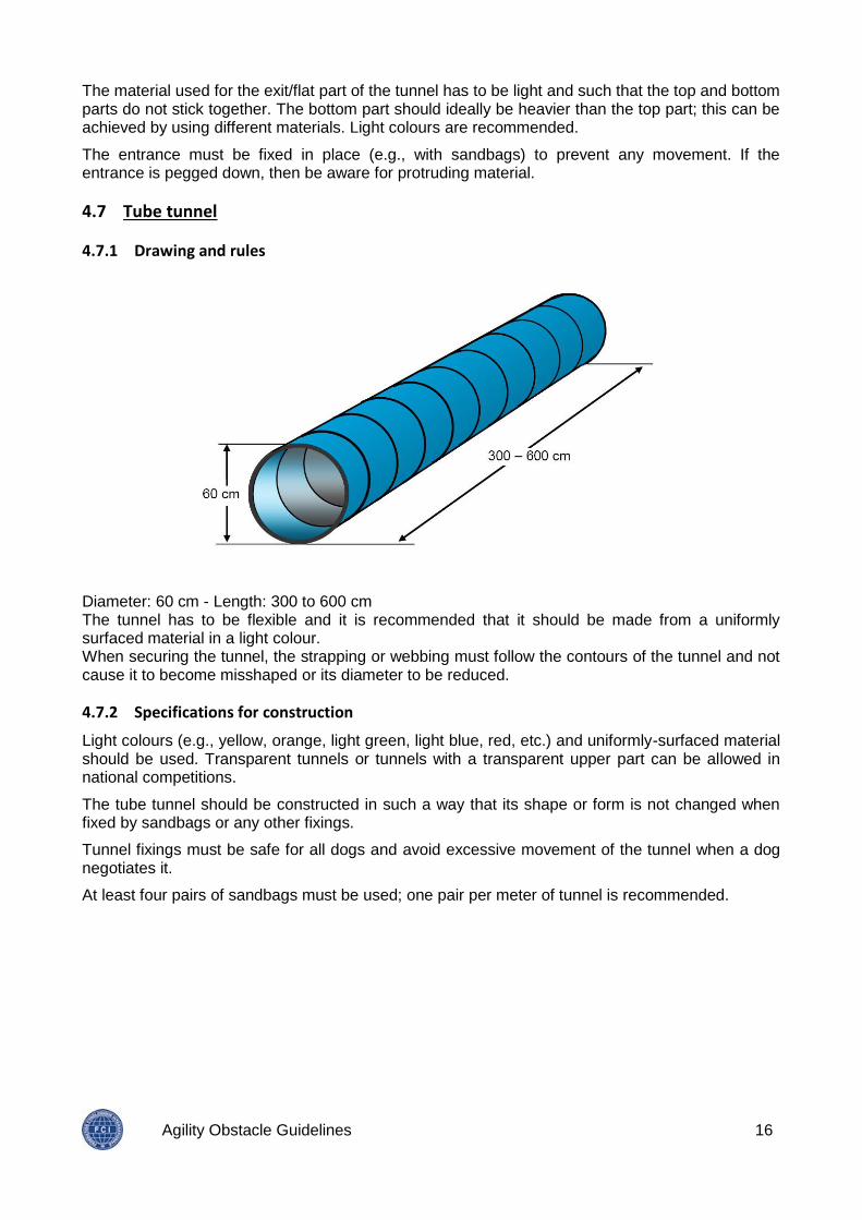
Diameter: 60 cm - Length: 300 to 600 cm The tunnel has to be flexible and it is recommended that it should be made from a uniformly surfaced material in a light colour. When securing the tunnel, the strapping or webbing must follow the contours of the tunnel and not cause it to become misshaped or its diameter to be reduced.
4.7.2 Specifications for construction
Light colours (e.g., yellow, orange, light green, light blue, red, etc.) and uniformly-surfaced material should be used. Transparent tunnels or tunnels with a transparent upper part can be allowed in national competitions.
The tube tunnel should be constructed in such a way that its shape or form is not changed when fixed by sandbags or any other fixings.
Tunnel fixings must be safe for all dogs and avoid excessive movement of the tunnel when a dog negotiates it.
At least four pairs of sandbags must be used; one pair per meter of tunnel is recommended.
Agility Obstacle Guidelines 17
4.8 Weave poles
4.8.1 Drawing and rules
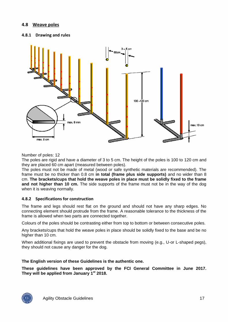
Number of poles: 12 The poles are rigid and have a diameter of 3 to 5 cm. The height of the poles is 100 to 120 cm and they are placed 60 cm apart (measured between poles). The poles must not be made of metal (wood or safe synthetic materials are recommended). The frame must be no thicker than 0.8 cm in total (frame plus side supports) and no wider than 8 cm. The brackets/cups that hold the weave poles in place must be solidly fixed to the frame and not higher than 10 cm. The side supports of the frame must not be in the way of the dog when it is weaving normally.
4.8.2 Specifications for construction
The frame and legs should rest flat on the ground and should not have any sharp edges. No connecting element should protrude from the frame. A reasonable tolerance to the thickness of the frame is allowed when two parts are connected together.
Colours of the poles should be contrasting either from top to bottom or between consecutive poles.
Any brackets/cups that hold the weave poles in place should be solidly fixed to the base and be no higher than 10 cm.
When additional fixings are used to prevent the obstacle from moving (e.g., U-or L-shaped pegs), they should not cause any danger for the dog.
The English version of these Guidelines is the authentic one.
These guidelines have been approved by the FCI General Committee in June 2017. They will be applied from January 1st 2018.