Embed Size (px)
Citation preview
Federal Aviation Administration
EFB Electromagnetic Compatibility Assessment - Revision – Original – 08-22-2013 Page 1 of 18
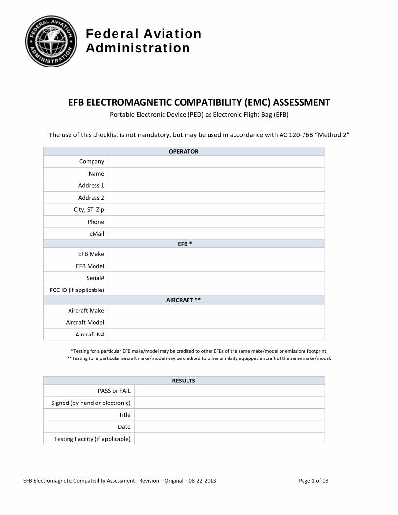
EFB ELECTROMAGNETIC COMPATIBILITY (EMC) ASSESSMENT Portable Electronic Device (PED) as Electronic Flight Bag (EFB)
The use of this checklist is not mandatory, but may be used in accordance with AC 120-76B “Method 2”
OPERATOR Company
Name Address 1 Address 2
City, ST, Zip Phone eMail
EFB * EFB Make
EFB Model Serial#
FCC ID (if applicable) AIRCRAFT **
Aircraft Make Aircraft Model
Aircraft N#
*Testing for a particular EFB make/model may be credited to other EFBs of the same make/model or emissions footprint. **Testing for a particular aircraft make/model may be credited to other similarly equipped aircraft of the same make/model.
RESULTS PASS or FAIL
Signed (by hand or electronic) Title Date
Testing Facility (if applicable)
Federal Aviation Administration
EFB Electromagnetic Compatibility Assessment - Revision – Original – 08-22-2013 Page 2 of 18
TABLE OF CONTENTS
INTRODUCTION ................................................................................................................................................ 3
APPLICABILITY .................................................................................................................................................. 3
REFERENCE DOCUMENTS ................................................................................................................................. 4
GENERAL .......................................................................................................................................................... 4
TEST REQUIREMENTS ................................................................................................................................. 4 TEST ENVIRONMENT .................................................................................................................................. 4 INSTRUCTIONS FOR COMPLETING THE REPORT ........................................................................................ 4
PHASE 1 – GROUND TEST PROCEDURE ............................................................................................................ 5
TEST SETUP................................................................................................................................................. 5 GROUND TESTING AND RESULTS ............................................................................................................... 6
A. VHF COMM RECEIVER ................................................................................................................... 6 B. VHF COMM TRANSMITTER ............................................................................................................ 6 C. VHF NAV AND DME TRANSMITTER/RECEIVER .............................................................................. 7 D. MARKER BEACON .......................................................................................................................... 9 E. ADF RECEIVER .............................................................................................................................. 10 F. FLIGHT DIRECTOR/AUTOPILOT .................................................................................................... 11 G. CABIN PAGING SYSTEM ............................................................................................................... 11 H. COMPASS SYSTEMS ..................................................................................................................... 11 I. HF RECEIVER ................................................................................................................................. 12 J. HF TRANSMITTER ......................................................................................................................... 12 K. GPS/FMS POSITION ..................................................................................................................... 12 L. OTHER AIRCRAFT SYSTEMS .......................................................................................................... 13
PHASE 2 – FLIGHT TEST PROCEDURE ............................................................................................................. 14
APPENDIX A: VHF, UHF & DME FREQUENCY PAIRING INFORMATION .......................................................... 15
Federal Aviation Administration
EFB Electromagnetic Compatibility Assessment - Revision – Original – 08-22-2013 Page 3 of 18
INTRODUCTION This document provides step-by-step test procedures to demonstrate electromagnetic compatibility for a portable (secured and viewable) or mounted Electronic Flight Bag. These checks ensure that the PED/EFB will not have any adverse effects on previously installed aircraft systems, or that the airplane equipment will induce a change in the PED/EFB display or other functions.
NOTE: This checklist is not intended to replace or supersede the aircraft certification requirements for High Intensity Radiated Fields (HIRF) or PED tolerance (RTCA DO-307). The objective of this checklist is to aid the operator in an assessment of risk in the operation of an FCC compliant portable electronic device used as an EFB or portable GNSS source. Unique from other PEDs, these devices are controlled by the operator, with known emissions, tested in specific locations, and subject to ground and flight checks. Additionally, EFB program implementation requires direct surveillance by the flight crew and line validation to ensure that the PED meets its intended function.
This test procedure must be performed and submitted for each model of EFB used and each model of aircraft you operate. Testing for a particular EFB make/model may be credited to other EFB make/model of similar emissions footprint. Testing for a particular aircraft make/model may be credited to other similarly equipped aircraft of the same make/model. Information pertaining to the emissions characteristics of PEDs is typically obtained from test reports resulting from qualification to standards such as RTCA/DO-160 section 21 (or equivalent) or applicable Federal Communications Commission (FCC) requirements. FCC test report data may be found at: http://transition.fcc.gov/oet/ea/fccid/. Examining the test data allows the operator relief from checking the listed frequencies for the avionics component; leaving only frequencies for which the test data depicts unusual peaks or is of particular interest. Applicable sections of the FCC test report include, but may not be limited to, those sections related to spurious and/or radiated emissions, addressing the requirements of CFR 47 15.205 and/or 15.209, 15.247(d).
NOTE 1: The test procedures in this checklist are not necessary if the aircraft and applicable avionics equipment has been demonstrated to be compliant RTCA/DO-307, Aircraft Design and Certification for Portable Electronic Device (PED) Tolerance, for both back door and front door coupling.”
“NOTE 2: Due to differences in production and certification standards, some PED devices intended for general consumer use meet applicable FCC regulations, but may not be fully compliant to RTCA/DO-160 section 21 aircraft equipment standards. In that case, the operator may use this document as an acceptable means of determining electromagnetic compatibility. Alternately, the operator may analyze a formal report on the device model, completed according to RTCA DO-160 section 21, and use the method of testing outlined here, against the specific frequencies from the test report that exceed the envelope of the DO-160 standard.
APPLICABILITY Electromagnetic compatibility (EMC) testing, also known as EMI/Electromagnetic non-interference testing, is required for certain operators (e.g., 14 CFR Part 91K, Part 135 and Part 121) that intend to use an Electronic Flight Bag during critical phases of flight. Refer to the policy documents, below. FAA policy [AC 120-76B, 11.f.(2)] outlines two acceptable methods for achieving the objective. This document is used in conjunction with “Method 2”.
Test results are submitted to your Principle Operations Inspector (POI) as part of your EFB application package, in pursuit of OpSpec or MSpec A061 authorization for use of Electronic Flight Bags. For users operating under 14 CFR Part 91 Subpart F, test records are retained as part of “self compliance.”
Federal Aviation Administration
EFB Electromagnetic Compatibility Assessment - Revision – Original – 08-22-2013 Page 4 of 18
REFERENCE DOCUMENTS Compliance with these procedures is in accordance with the following FAA documents.
• FAA AC 120-76B, “Guidelines for the Certification, Airworthiness, & Operational Use of Portable Electronic Flight Bags”
• FAA AC 91.21-1B, “Use of Portable Electronic Devices Aboard Aircraft” • FAA Order 8900.1 Volume 4, Chapter 15, Section 1, “Electronic Flight Bag Operational Authorization
Process” • FAA Information for Operators (InFO 11011), “The Apple iPad and Other Suitable Tablet Computing
Devices as Electronic Flight Bags (EFB)”
These policies are subject to change in the future, which could impact the validity of this test procedure. You are required to follow current EFB policies, so we recommend that you monitor and review policies as they are revised.
GENERAL
TEST REQUIREMENTS Prior to performing Ground and Flight checks, verify that the EFB(s) and all aircraft systems are working properly.
TEST ENVIRONMENT The test environment should be free from electromagnetic influence that has the potential to affect test results. All ground checks should be conducted away from other operating aircraft, with sufficient power applied to enable all aircraft systems, with engines running and all lighting on.
INSTRUCTIONS FOR COMPLETING THE REPORT • Complete the cover page with all requested details about the aircraft operator, the representative EFB(s),
the aircraft fleet, the specific aircraft used, and the person(s) performing the test. • In the spaces designated "RESULTS“, place a checkmark or an “X” in the field under “SAT” if the step
produced satisfactory results, under “UNSAT” if the results were unsatisfactory, or under “N/A” if the test section is Not Applicable. For any N/A response, add a short comment as to why it is not applicable.
• In the space called “COMMENTS,” add any additional written comments if appropriate to explain a situation or to add clarity.
(continued)
Federal Aviation Administration
EFB Electromagnetic Compatibility Assessment - Revision – Original – 08-22-2013 Page 5 of 18
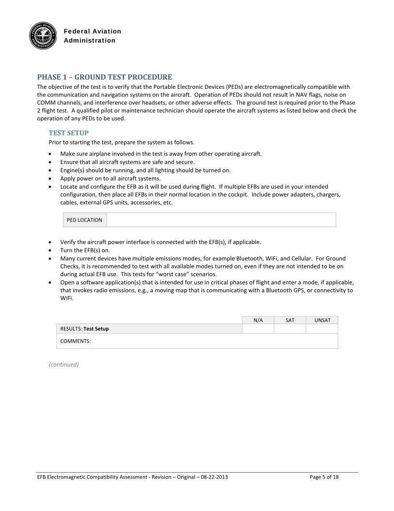
PHASE 1 – GROUND TEST PROCEDURE The objective of the test is to verify that the Portable Electronic Devices (PEDs) are electromagnetically compatible with the communication and navigation systems on the aircraft. Operation of PEDs should not result in NAV flags, noise on COMM channels, and interference over headsets, or other adverse effects. The ground test is required prior to the Phase 2 flight test. A qualified pilot or maintenance technician should operate the aircraft systems as listed below and check the operation of any PEDs to be used.
TEST SETUP Prior to starting the test, prepare the system as follows.
• Make sure airplane involved in the test is away from other operating aircraft. • Ensure that all aircraft systems are safe and secure. • Engine(s) should be running, and all lighting should be turned on. • Apply power on to all aircraft systems. • Locate and configure the EFB as it will be used during flight. If multiple EFBs are used in your intended
configuration, then place all EFBs in their normal location in the cockpit. Include power adapters, chargers, cables, external GPS units, accessories, etc.
PED LOCATION
• Verify the aircraft power interface is connected with the EFB(s), if applicable. • Turn the EFB(s) on. • Many current devices have multiple emissions modes, for example Bluetooth, WiFi, and Cellular. For Ground
Checks, it is recommended to test with all available modes turned on, even if they are not intended to be on during actual EFB use. This tests for “worst case” scenarios.
• Open a software application(s) that is intended for use in critical phases of flight and enter a mode, if applicable, that invokes radio emissions, e.g., a moving map that is communicating with a Bluetooth GPS, or connectivity to WiFi.
N/A SAT UNSAT RESULTS: Test Setup
COMMENTS:
(continued)
Federal Aviation Administration
EFB Electromagnetic Compatibility Assessment - Revision – Original – 08-22-2013 Page 6 of 18
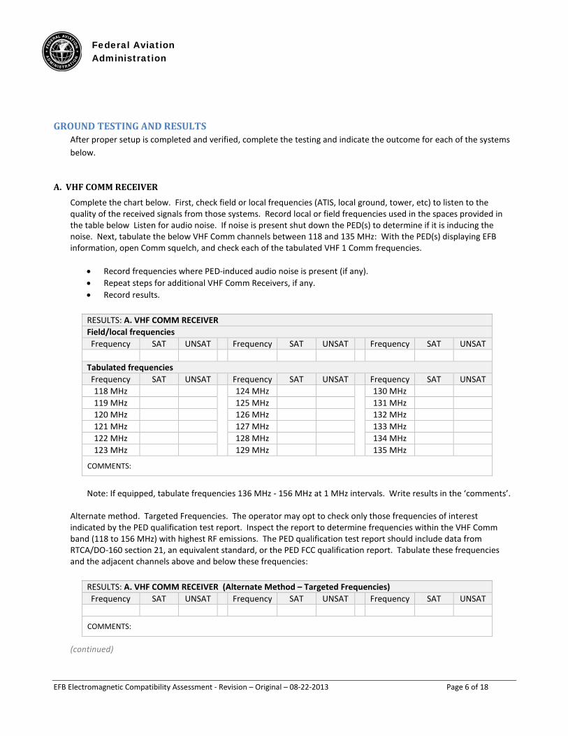
GROUND TESTING AND RESULTS After proper setup is completed and verified, complete the testing and indicate the outcome for each of the systems below.
A. VHF COMM RECEIVER Complete the chart below. First, check field or local frequencies (ATIS, local ground, tower, etc) to listen to the quality of the received signals from those systems. Record local or field frequencies used in the spaces provided in the table below Listen for audio noise. If noise is present shut down the PED(s) to determine if it is inducing the noise. Next, tabulate the below VHF Comm channels between 118 and 135 MHz: With the PED(s) displaying EFB information, open Comm squelch, and check each of the tabulated VHF 1 Comm frequencies.
• Record frequencies where PED-induced audio noise is present (if any). • Repeat steps for additional VHF Comm Receivers, if any. • Record results.
RESULTS: A. VHF COMM RECEIVER Field/local frequencies Frequency SAT UNSAT Frequency SAT UNSAT Frequency SAT UNSAT
Tabulated frequencies Frequency SAT UNSAT Frequency SAT UNSAT Frequency SAT UNSAT 118 MHz 124 MHz 130 MHz 119 MHz 125 MHz 131 MHz 120 MHz 126 MHz 132 MHz 121 MHz 127 MHz 133 MHz 122 MHz 128 MHz 134 MHz 123 MHz 129 MHz 135 MHz
COMMENTS:
Note: If equipped, tabulate frequencies 136 MHz - 156 MHz at 1 MHz intervals. Write results in the ‘comments’.
Alternate method. Targeted Frequencies. The operator may opt to check only those frequencies of interest indicated by the PED qualification test report. Inspect the report to determine frequencies within the VHF Comm band (118 to 156 MHz) with highest RF emissions. The PED qualification test report should include data from RTCA/DO-160 section 21, an equivalent standard, or the PED FCC qualification report. Tabulate these frequencies and the adjacent channels above and below these frequencies:
RESULTS: A. VHF COMM RECEIVER (Alternate Method – Targeted Frequencies) Frequency SAT UNSAT Frequency SAT UNSAT Frequency SAT UNSAT
COMMENTS:
(continued)
Federal Aviation Administration
EFB Electromagnetic Compatibility Assessment - Revision – Original – 08-22-2013 Page 7 of 18
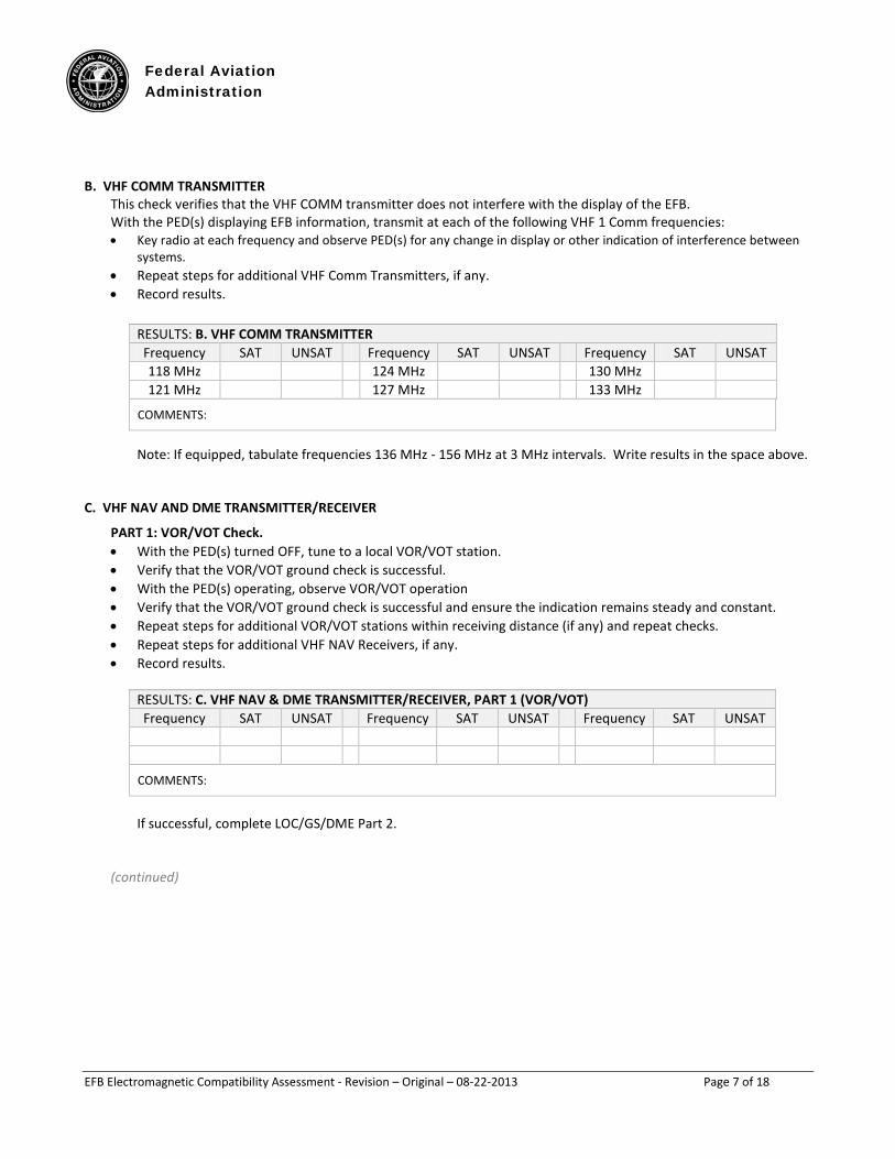
B. VHF COMM TRANSMITTER This check verifies that the VHF COMM transmitter does not interfere with the display of the EFB. With the PED(s) displaying EFB information, transmit at each of the following VHF 1 Comm frequencies: • Key radio at each frequency and observe PED(s) for any change in display or other indication of interference between
systems. • Repeat steps for additional VHF Comm Transmitters, if any. • Record results.
RESULTS: B. VHF COMM TRANSMITTER Frequency SAT UNSAT Frequency SAT UNSAT Frequency SAT UNSAT 118 MHz 124 MHz 130 MHz 121 MHz 127 MHz 133 MHz
COMMENTS: Note: If equipped, tabulate frequencies 136 MHz - 156 MHz at 3 MHz intervals. Write results in the space above.
C. VHF NAV AND DME TRANSMITTER/RECEIVER
PART 1: VOR/VOT Check. • With the PED(s) turned OFF, tune to a local VOR/VOT station. • Verify that the VOR/VOT ground check is successful. • With the PED(s) operating, observe VOR/VOT operation • Verify that the VOR/VOT ground check is successful and ensure the indication remains steady and constant. • Repeat steps for additional VOR/VOT stations within receiving distance (if any) and repeat checks. • Repeat steps for additional VHF NAV Receivers, if any. • Record results.
RESULTS: C. VHF NAV & DME TRANSMITTER/RECEIVER, PART 1 (VOR/VOT) Frequency SAT UNSAT Frequency SAT UNSAT Frequency SAT UNSAT
COMMENTS:
If successful, complete LOC/GS/DME Part 2.
(continued)
Federal Aviation Administration
EFB Electromagnetic Compatibility Assessment - Revision – Original – 08-22-2013 Page 8 of 18
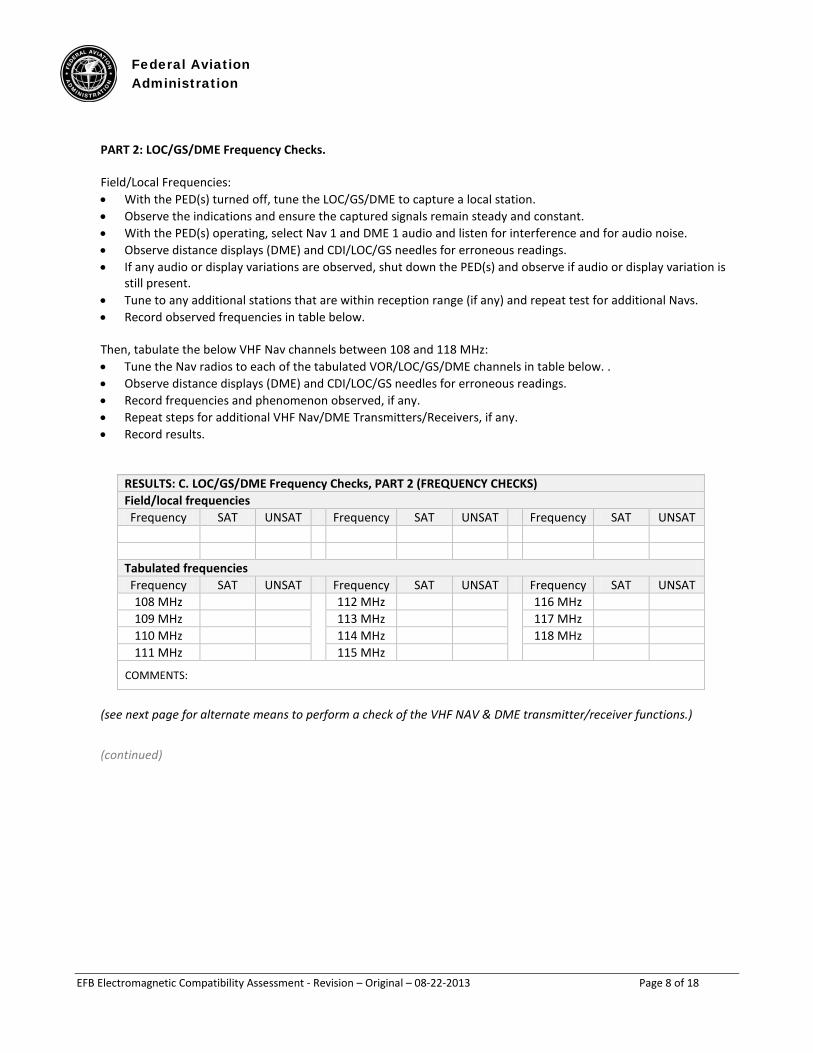
PART 2: LOC/GS/DME Frequency Checks. Field/Local Frequencies: • With the PED(s) turned off, tune the LOC/GS/DME to capture a local station. • Observe the indications and ensure the captured signals remain steady and constant. • With the PED(s) operating, select Nav 1 and DME 1 audio and listen for interference and for audio noise. • Observe distance displays (DME) and CDI/LOC/GS needles for erroneous readings. • If any audio or display variations are observed, shut down the PED(s) and observe if audio or display variation is
still present. • Tune to any additional stations that are within reception range (if any) and repeat test for additional Navs. • Record observed frequencies in table below.
Then, tabulate the below VHF Nav channels between 108 and 118 MHz: • Tune the Nav radios to each of the tabulated VOR/LOC/GS/DME channels in table below. . • Observe distance displays (DME) and CDI/LOC/GS needles for erroneous readings. • Record frequencies and phenomenon observed, if any. • Repeat steps for additional VHF Nav/DME Transmitters/Receivers, if any. • Record results.
RESULTS: C. LOC/GS/DME Frequency Checks, PART 2 (FREQUENCY CHECKS) Field/local frequencies Frequency SAT UNSAT Frequency SAT UNSAT Frequency SAT UNSAT
Tabulated frequencies Frequency SAT UNSAT Frequency SAT UNSAT Frequency SAT UNSAT 108 MHz 112 MHz 116 MHz 109 MHz 113 MHz 117 MHz 110 MHz 114 MHz 118 MHz 111 MHz 115 MHz
COMMENTS:
(see next page for alternate means to perform a check of the VHF NAV & DME transmitter/receiver functions.)
(continued)
Federal Aviation Administration
EFB Electromagnetic Compatibility Assessment - Revision – Original – 08-22-2013 Page 9 of 18
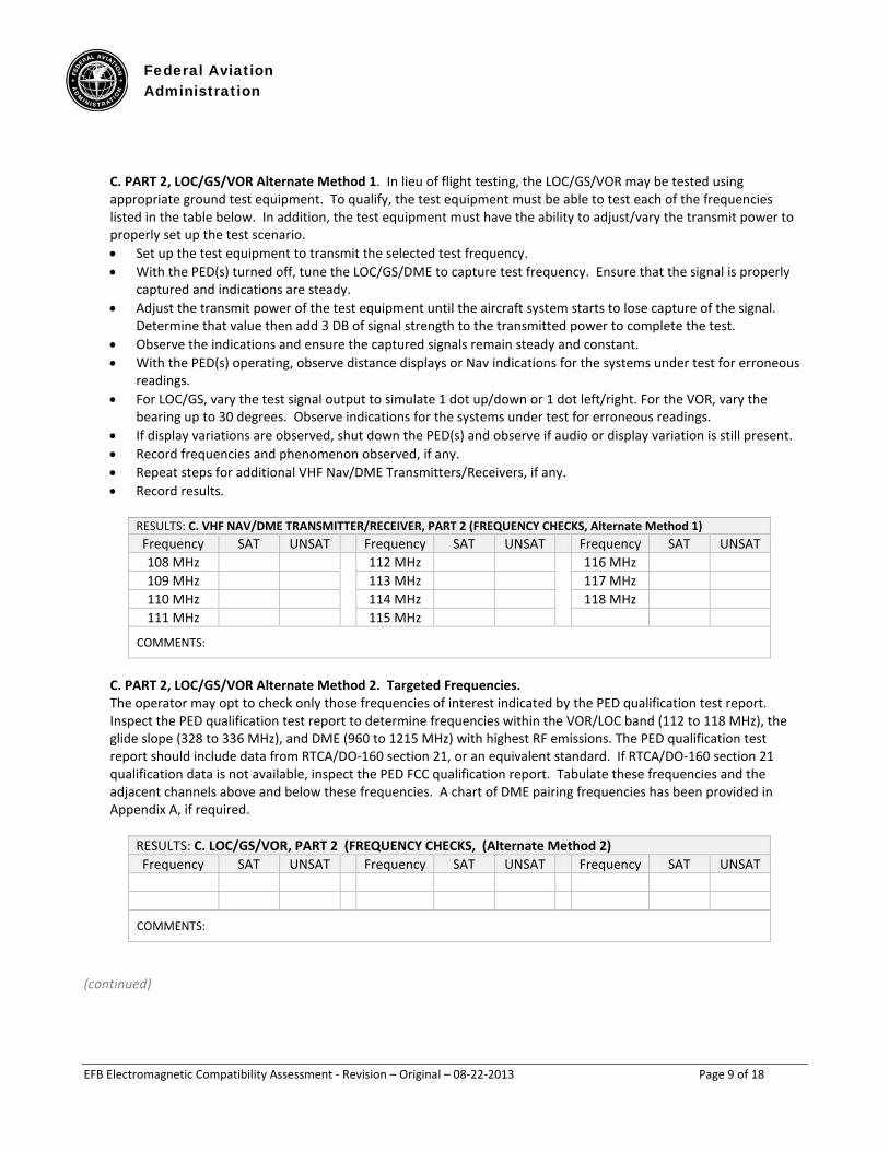
C. PART 2, LOC/GS/VOR Alternate Method 1. In lieu of flight testing, the LOC/GS/VOR may be tested using appropriate ground test equipment. To qualify, the test equipment must be able to test each of the frequencies listed in the table below. In addition, the test equipment must have the ability to adjust/vary the transmit power to properly set up the test scenario. • Set up the test equipment to transmit the selected test frequency. • With the PED(s) turned off, tune the LOC/GS/DME to capture test frequency. Ensure that the signal is properly
captured and indications are steady. • Adjust the transmit power of the test equipment until the aircraft system starts to lose capture of the signal.
Determine that value then add 3 DB of signal strength to the transmitted power to complete the test. • Observe the indications and ensure the captured signals remain steady and constant. • With the PED(s) operating, observe distance displays or Nav indications for the systems under test for erroneous
readings. • For LOC/GS, vary the test signal output to simulate 1 dot up/down or 1 dot left/right. For the VOR, vary the
bearing up to 30 degrees. Observe indications for the systems under test for erroneous readings. • If display variations are observed, shut down the PED(s) and observe if audio or display variation is still present. • Record frequencies and phenomenon observed, if any. • Repeat steps for additional VHF Nav/DME Transmitters/Receivers, if any. • Record results.
RESULTS: C. VHF NAV/DME TRANSMITTER/RECEIVER, PART 2 (FREQUENCY CHECKS, Alternate Method 1) Frequency SAT UNSAT Frequency SAT UNSAT Frequency SAT UNSAT 108 MHz 112 MHz 116 MHz 109 MHz 113 MHz 117 MHz 110 MHz 114 MHz 118 MHz 111 MHz 115 MHz
COMMENTS:
C. PART 2, LOC/GS/VOR Alternate Method 2. Targeted Frequencies. The operator may opt to check only those frequencies of interest indicated by the PED qualification test report. Inspect the PED qualification test report to determine frequencies within the VOR/LOC band (112 to 118 MHz), the glide slope (328 to 336 MHz), and DME (960 to 1215 MHz) with highest RF emissions. The PED qualification test report should include data from RTCA/DO-160 section 21, or an equivalent standard. If RTCA/DO-160 section 21 qualification data is not available, inspect the PED FCC qualification report. Tabulate these frequencies and the adjacent channels above and below these frequencies. A chart of DME pairing frequencies has been provided in Appendix A, if required.
RESULTS: C. LOC/GS/VOR, PART 2 (FREQUENCY CHECKS, (Alternate Method 2) Frequency SAT UNSAT Frequency SAT UNSAT Frequency SAT UNSAT
COMMENTS:
(continued)
Federal Aviation Administration
EFB Electromagnetic Compatibility Assessment - Revision – Original – 08-22-2013 Page 10 of 18
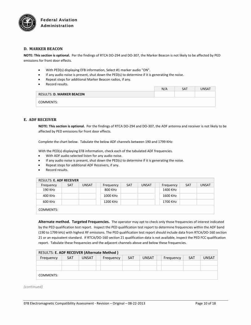
D. MARKER BEACON NOTE: This section is optional. Per the findings of RTCA DO-294 and DO-307, the Marker Beacon is not likely to be affected by PED emissions for front door effects.
• With PED(s) displaying EFB information, Select #1 marker audio "ON". • If any audio noise is present, shut down the PED(s) to determine if it is generating the noise. • Repeat steps for additional Marker Beacon radios, if any. • Record results. N/A SAT UNSAT RESULTS: D. MARKER BEACON
COMMENTS:
E. ADF RECEIVER NOTE: This section is optional. Per the findings of RTCA DO-294 and DO-307, the ADF antenna and receiver is not likely to be affected by PED emissions for front door effects. Complete the chart below. Tabulate the below ADF channels between 190 and 1799 KHz:
With the PED(s) displaying EFB information, check each of the tabulated ADF frequencies. • With ADF audio selected listen for any audio noise. • If any audio noise is present, shut down the PED(s) to determine if it is generating the noise. • Repeat steps for additional ADF Receivers, if any. • Record results.
RESULTS: E. ADF RECEIVER Frequency SAT UNSAT Frequency SAT UNSAT Frequency SAT UNSAT
190 KHz 800 KHz 1400 KHz
400 KHz 1000 KHz 1600 KHz
600 KHz 1200 KHz 1700 KHz
COMMENTS:
Alternate method. Targeted Frequencies. The operator may opt to check only those frequencies of interest indicated by the PED qualification test report. Inspect the PED qualification test report to determine frequencies within the ADF band (190 to 1799 kHz) with highest RF emissions. The PED qualification test report should include data from RTCA/DO-160 section 21 or an equivalent standard. If RTCA/DO-160 section 21 qualification data is not available, inspect the PED FCC qualification report. Tabulate these frequencies and the adjacent channels above and below these frequencies.
RESULTS: E. ADF RECEIVER (Alternate Method ) Frequency SAT UNSAT Frequency SAT UNSAT Frequency SAT UNSAT
COMMENTS:
(continued)
Federal Aviation Administration
EFB Electromagnetic Compatibility Assessment - Revision – Original – 08-22-2013 Page 11 of 18
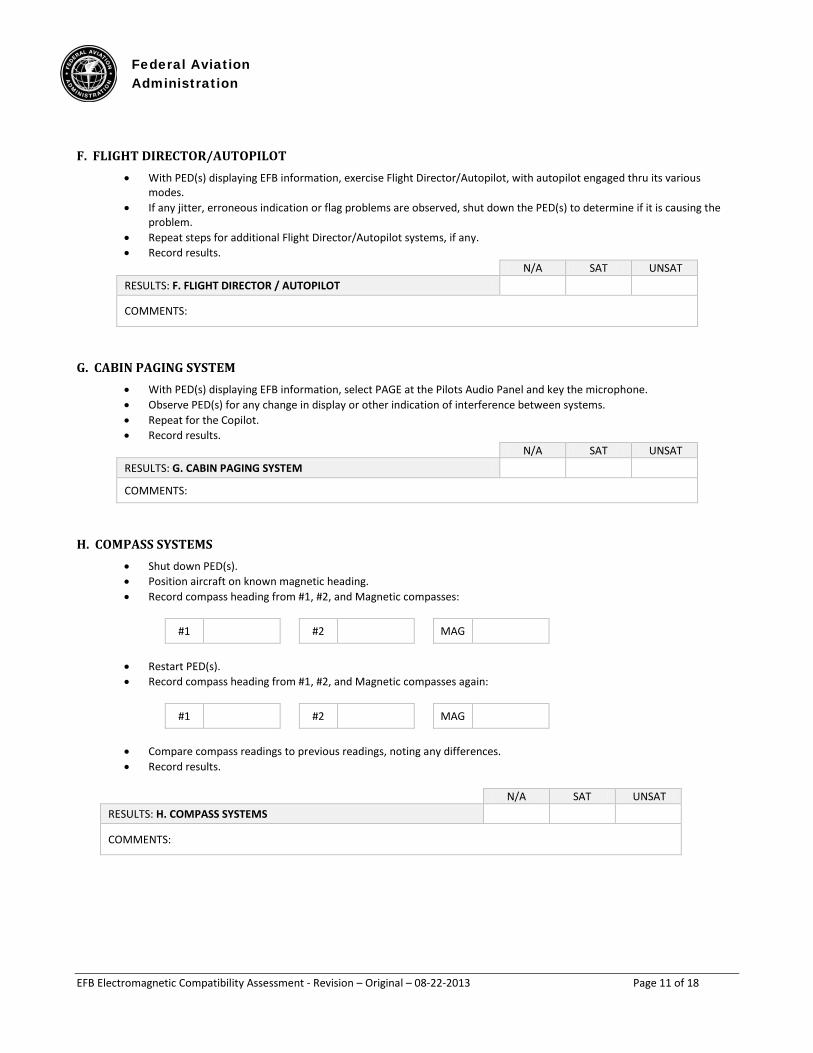
F. FLIGHT DIRECTOR/AUTOPILOT • With PED(s) displaying EFB information, exercise Flight Director/Autopilot, with autopilot engaged thru its various
modes. • If any jitter, erroneous indication or flag problems are observed, shut down the PED(s) to determine if it is causing the
problem. • Repeat steps for additional Flight Director/Autopilot systems, if any. • Record results. N/A SAT UNSAT RESULTS: F. FLIGHT DIRECTOR / AUTOPILOT
COMMENTS:
G. CABIN PAGING SYSTEM • With PED(s) displaying EFB information, select PAGE at the Pilots Audio Panel and key the microphone. • Observe PED(s) for any change in display or other indication of interference between systems. • Repeat for the Copilot. • Record results. N/A SAT UNSAT RESULTS: G. CABIN PAGING SYSTEM
COMMENTS:
H. COMPASS SYSTEMS • Shut down PED(s). • Position aircraft on known magnetic heading. • Record compass heading from #1, #2, and Magnetic compasses:
#1 #2 MAG
• Restart PED(s). • Record compass heading from #1, #2, and Magnetic compasses again:
#1 #2 MAG
• Compare compass readings to previous readings, noting any differences. • Record results.
N/A SAT UNSAT RESULTS: H. COMPASS SYSTEMS
COMMENTS:
Federal Aviation Administration
EFB Electromagnetic Compatibility Assessment - Revision – Original – 08-22-2013 Page 12 of 18
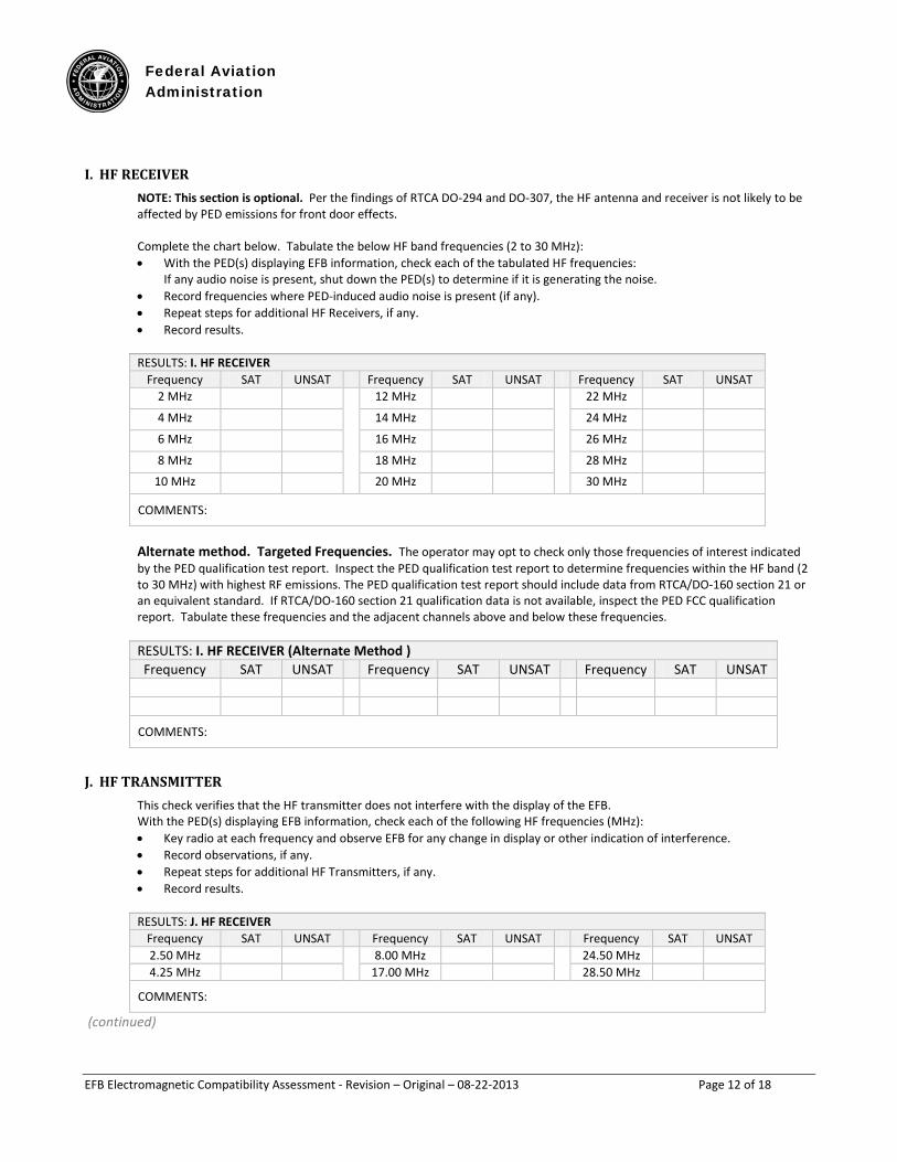
I. HF RECEIVER NOTE: This section is optional. Per the findings of RTCA DO-294 and DO-307, the HF antenna and receiver is not likely to be affected by PED emissions for front door effects. Complete the chart below. Tabulate the below HF band frequencies (2 to 30 MHz): • With the PED(s) displaying EFB information, check each of the tabulated HF frequencies:
If any audio noise is present, shut down the PED(s) to determine if it is generating the noise. • Record frequencies where PED-induced audio noise is present (if any). • Repeat steps for additional HF Receivers, if any. • Record results. RESULTS: I. HF RECEIVER
Frequency SAT UNSAT Frequency SAT UNSAT Frequency SAT UNSAT 2 MHz 12 MHz 22 MHz
4 MHz 14 MHz 24 MHz
6 MHz 16 MHz 26 MHz
8 MHz 18 MHz 28 MHz
10 MHz 20 MHz 30 MHz
COMMENTS:
Alternate method. Targeted Frequencies. The operator may opt to check only those frequencies of interest indicated by the PED qualification test report. Inspect the PED qualification test report to determine frequencies within the HF band (2 to 30 MHz) with highest RF emissions. The PED qualification test report should include data from RTCA/DO-160 section 21 or an equivalent standard. If RTCA/DO-160 section 21 qualification data is not available, inspect the PED FCC qualification report. Tabulate these frequencies and the adjacent channels above and below these frequencies.
RESULTS: I. HF RECEIVER (Alternate Method ) Frequency SAT UNSAT Frequency SAT UNSAT Frequency SAT UNSAT
COMMENTS:
J. HF TRANSMITTER This check verifies that the HF transmitter does not interfere with the display of the EFB. With the PED(s) displaying EFB information, check each of the following HF frequencies (MHz): • Key radio at each frequency and observe EFB for any change in display or other indication of interference. • Record observations, if any. • Repeat steps for additional HF Transmitters, if any. • Record results.
RESULTS: J. HF RECEIVER
Frequency SAT UNSAT Frequency SAT UNSAT Frequency SAT UNSAT 2.50 MHz 8.00 MHz 24.50 MHz 4.25 MHz 17.00 MHz 28.50 MHz
COMMENTS:
(continued)
Federal Aviation Administration
EFB Electromagnetic Compatibility Assessment - Revision – Original – 08-22-2013 Page 13 of 18
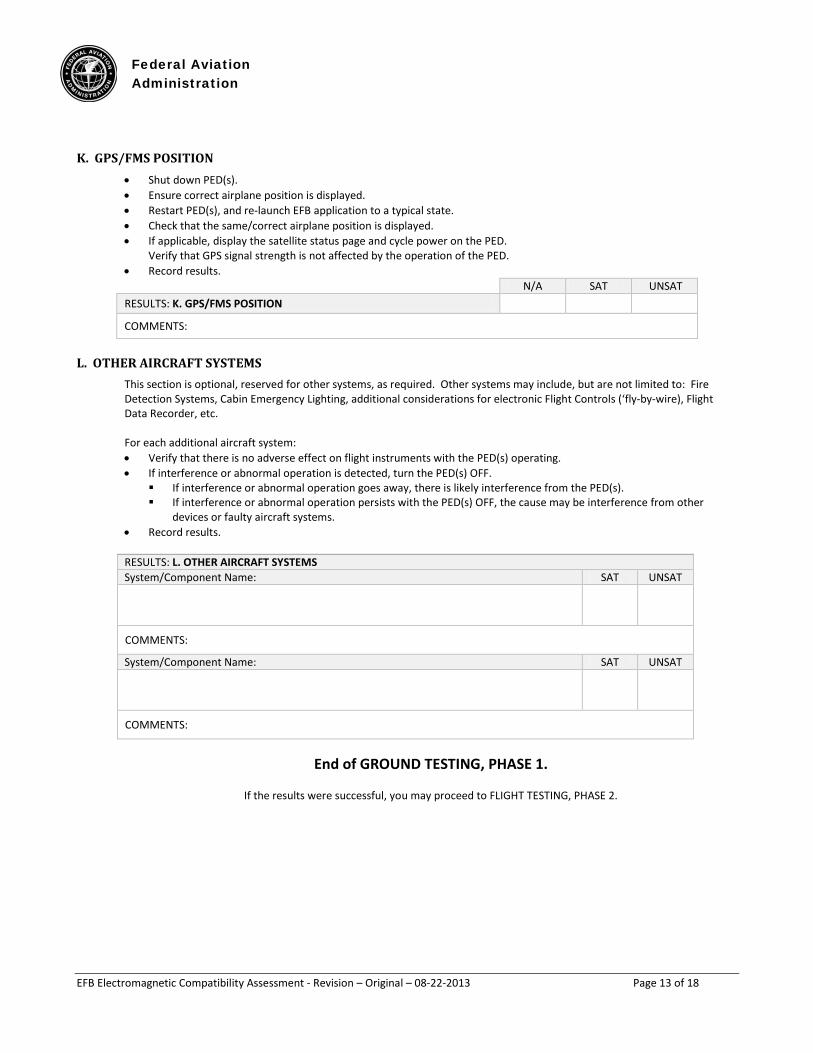
K. GPS/FMS POSITION • Shut down PED(s). • Ensure correct airplane position is displayed. • Restart PED(s), and re-launch EFB application to a typical state. • Check that the same/correct airplane position is displayed. • If applicable, display the satellite status page and cycle power on the PED.
Verify that GPS signal strength is not affected by the operation of the PED. • Record results. N/A SAT UNSAT RESULTS: K. GPS/FMS POSITION
COMMENTS:
L. OTHER AIRCRAFT SYSTEMS This section is optional, reserved for other systems, as required. Other systems may include, but are not limited to: Fire Detection Systems, Cabin Emergency Lighting, additional considerations for electronic Flight Controls (‘fly-by-wire), Flight Data Recorder, etc. For each additional aircraft system: • Verify that there is no adverse effect on flight instruments with the PED(s) operating. • If interference or abnormal operation is detected, turn the PED(s) OFF.
If interference or abnormal operation goes away, there is likely interference from the PED(s). If interference or abnormal operation persists with the PED(s) OFF, the cause may be interference from other
devices or faulty aircraft systems. • Record results. RESULTS: L. OTHER AIRCRAFT SYSTEMS System/Component Name: SAT UNSAT
COMMENTS:
System/Component Name: SAT UNSAT
COMMENTS:
End of GROUND TESTING, PHASE 1.
If the results were successful, you may proceed to FLIGHT TESTING, PHASE 2.
Federal Aviation Administration
EFB Electromagnetic Compatibility Assessment - Revision – Original – 08-22-2013 Page 14 of 18
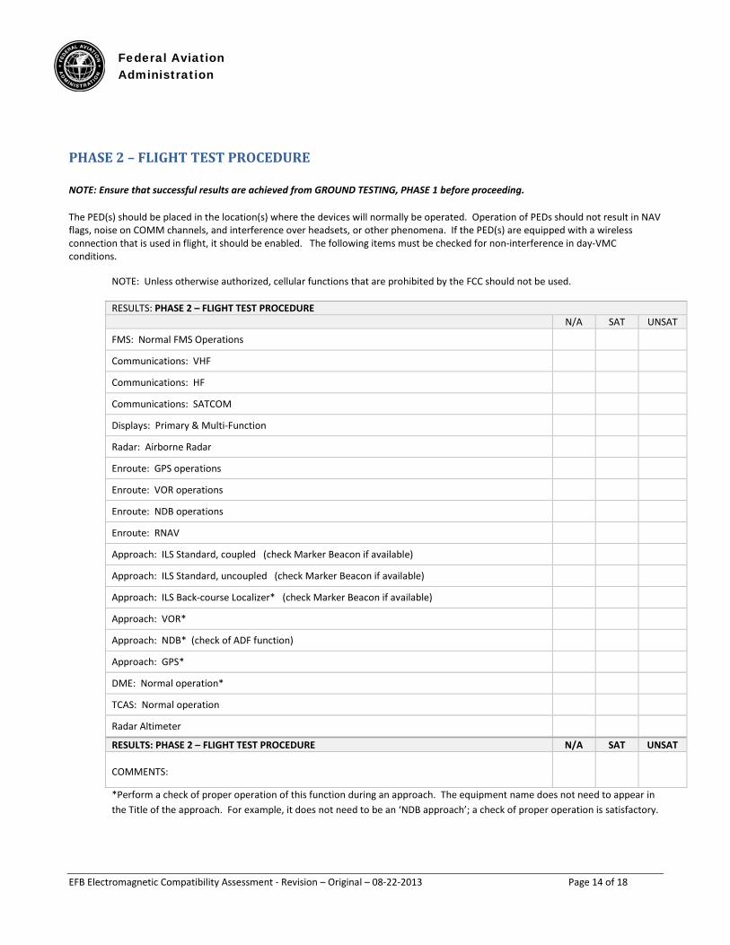
PHASE 2 – FLIGHT TEST PROCEDURE NOTE: Ensure that successful results are achieved from GROUND TESTING, PHASE 1 before proceeding.
The PED(s) should be placed in the location(s) where the devices will normally be operated. Operation of PEDs should not result in NAV flags, noise on COMM channels, and interference over headsets, or other phenomena. If the PED(s) are equipped with a wireless connection that is used in flight, it should be enabled. The following items must be checked for non-interference in day-VMC conditions.
NOTE: Unless otherwise authorized, cellular functions that are prohibited by the FCC should not be used. RESULTS: PHASE 2 – FLIGHT TEST PROCEDURE N/A SAT UNSAT
FMS: Normal FMS Operations
Communications: VHF
Communications: HF
Communications: SATCOM
Displays: Primary & Multi-Function
Radar: Airborne Radar
Enroute: GPS operations
Enroute: VOR operations
Enroute: NDB operations
Enroute: RNAV
Approach: ILS Standard, coupled (check Marker Beacon if available)
Approach: ILS Standard, uncoupled (check Marker Beacon if available)
Approach: ILS Back-course Localizer* (check Marker Beacon if available)
Approach: VOR*
Approach: NDB* (check of ADF function)
Approach: GPS*
DME: Normal operation*
TCAS: Normal operation
Radar Altimeter
RESULTS: PHASE 2 – FLIGHT TEST PROCEDURE N/A SAT UNSAT COMMENTS:
*Perform a check of proper operation of this function during an approach. The equipment name does not need to appear in the Title of the approach. For example, it does not need to be an ‘NDB approach’; a check of proper operation is satisfactory.
Federal Aviation Administration
EFB Electromagnetic Compatibility Assessment - Revision – Original – 08-22-2013 Page 15 of 18
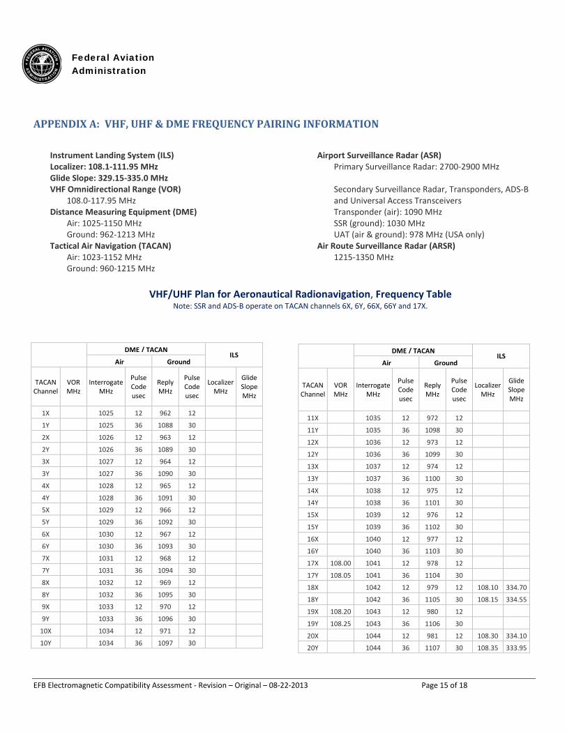
APPENDIX A: VHF, UHF & DME FREQUENCY PAIRING INFORMATION
Instrument Landing System (ILS) Localizer: 108.1-111.95 MHz Glide Slope: 329.15-335.0 MHz VHF Omnidirectional Range (VOR)
108.0-117.95 MHz Distance Measuring Equipment (DME)
Air: 1025-1150 MHz Ground: 962-1213 MHz
Tactical Air Navigation (TACAN) Air: 1023-1152 MHz Ground: 960-1215 MHz
Airport Surveillance Radar (ASR) Primary Surveillance Radar: 2700-2900 MHz Secondary Surveillance Radar, Transponders, ADS-B and Universal Access Transceivers Transponder (air): 1090 MHz SSR (ground): 1030 MHz UAT (air & ground): 978 MHz (USA only)
Air Route Surveillance Radar (ARSR) 1215-1350 MHz
VHF/UHF Plan for Aeronautical Radionavigation, Frequency Table
Note: SSR and ADS-B operate on TACAN channels 6X, 6Y, 66X, 66Y and 17X.
DME / TACAN
ILS Air Ground
TACAN Channel
VOR MHz
Interrogate MHz
Pulse Code usec
Reply MHz
Pulse Code usec
Localizer MHz
Glide Slope MHz
1X 1025 12 962 12 1Y 1025 36 1088 30 2X 1026 12 963 12 2Y 1026 36 1089 30 3X 1027 12 964 12 3Y 1027 36 1090 30 4X 1028 12 965 12 4Y 1028 36 1091 30 5X 1029 12 966 12 5Y 1029 36 1092 30 6X 1030 12 967 12 6Y 1030 36 1093 30 7X 1031 12 968 12 7Y 1031 36 1094 30 8X 1032 12 969 12 8Y 1032 36 1095 30 9X 1033 12 970 12 9Y 1033 36 1096 30
10X 1034 12 971 12 10Y 1034 36 1097 30
DME / TACAN
ILS Air Ground
TACAN Channel
VOR MHz
Interrogate MHz
Pulse Code usec
Reply MHz
Pulse Code usec
Localizer MHz
Glide Slope MHz
11X 1035 12 972 12 11Y 1035 36 1098 30 12X 1036 12 973 12 12Y 1036 36 1099 30 13X 1037 12 974 12 13Y 1037 36 1100 30 14X 1038 12 975 12 14Y 1038 36 1101 30 15X 1039 12 976 12 15Y 1039 36 1102 30 16X 1040 12 977 12 16Y 1040 36 1103 30 17X 108.00 1041 12 978 12 17Y 108.05 1041 36 1104 30 18X 1042 12 979 12 108.10 334.70
18Y 1042 36 1105 30 108.15 334.55
19X 108.20 1043 12 980 12 19Y 108.25 1043 36 1106 30 20X 1044 12 981 12 108.30 334.10
20Y 1044 36 1107 30 108.35 333.95
Federal Aviation Administration
EFB Electromagnetic Compatibility Assessment - Revision – Original – 08-21-2013 Page 16 of 18
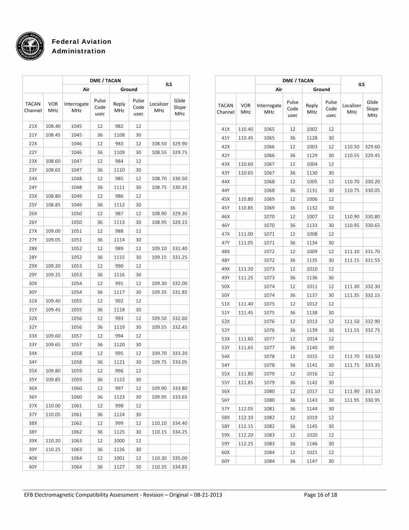
DME / TACAN
ILS Air Ground
TACAN Channel
VOR MHz
Interrogate MHz
Pulse Code usec
Reply MHz
Pulse Code usec
Localizer MHz
Glide Slope MHz
21X 108.40 1045 12 982 12 21Y 108.45 1045 36 1108 30 22X 1046 12 983 12 108.50 329.90
22Y 1046 36 1109 30 108.55 329.75
23X 108.60 1047 12 984 12 23Y 108.65 1047 36 1110 30 24X 1048 12 985 12 108.70 330.50
24Y 1048 36 1111 30 108.75 330.35
25X 108.80 1049 12 986 12 25Y 108.85 1049 36 1112 30 26X 1050 12 987 12 108.90 329.30
26Y 1050 36 1113 30 108.95 329.15
27X 109.00 1051 12 988 12 27Y 109.05 1051 36 1114 30 28X 1052 12 989 12 109.10 331.40
28Y 1052 36 1115 30 109.15 331.25
29X 109.20 1053 12 990 12 29Y 109.25 1053 36 1116 30 30X 1054 12 991 12 109.30 332.00
30Y 1054 36 1117 30 109.35 331.85
31X 109.40 1055 12 992 12 31Y 109.45 1055 36 1118 30 32X 1056 12 993 12 109.50 332.60
32Y 1056 36 1119 30 109.55 332.45
33X 109.60 1057 12 994 12 33Y 109.65 1057 36 1120 30 34X 1058 12 995 12 109.70 333.20
34Y 1058 36 1121 30 109.75 333.05
35X 109.80 1059 12 996 12 35Y 109.85 1059 36 1122 30 36X 1060 12 997 12 109.90 333.80
36Y 1060 36 1123 30 109.95 333.65
37X 110.00 1061 12 998 12 37Y 110.05 1061 36 1124 30 38X 1062 12 999 12 110.10 334.40
38Y 1062 36 1125 30 110.15 334.25
39X 110.20 1063 12 1000 12 39Y 110.25 1063 36 1126 30 40X 1064 12 1001 12 110.30 335.00
40Y 1064 36 1127 30 110.35 334.85
DME / TACAN
ILS Air Ground
TACAN Channel
VOR MHz
Interrogate MHz
Pulse Code usec
Reply MHz
Pulse Code usec
Localizer MHz
Glide Slope MHz
41X 110.40 1065 12 1002 12 41Y 110.45 1065 36 1128 30 42X 1066 12 1003 12 110.50 329.60
42Y 1066 36 1129 30 110.55 329.45
43X 110.60 1067 12 1004 12 43Y 110.65 1067 36 1130 30 44X 1068 12 1005 12 110.70 330.20
44Y 1068 36 1131 30 110.75 330.05
45X 110.80 1069 12 1006 12 45Y 110.85 1069 36 1132 30 46X 1070 12 1007 12 110.90 330.80
46Y 1070 36 1133 30 110.95 330.65
47X 111.00 1071 12 1008 12 47Y 111.05 1071 36 1134 30 48X 1072 12 1009 12 111.10 331.70
48Y 1072 36 1135 30 111.15 331.55
49X 111.20 1073 12 1010 12 49Y 111.25 1073 36 1136 30 50X 1074 12 1011 12 111.30 332.30
50Y 1074 36 1137 30 111.35 332.15
51X 111.40 1075 12 1012 12 51Y 111.45 1075 36 1138 30 52X 1076 12 1013 12 111.50 332.90
52Y 1076 36 1139 30 111.55 332.75
53X 111.60 1077 12 1014 12 53Y 111.65 1077 36 1140 30 54X 1078 12 1015 12 111.70 333.50
54Y 1078 36 1141 30 111.75 333.35
55X 111.80 1079 12 1016 12 55Y 111.85 1079 36 1142 30 56X 1080 12 1017 12 111.90 331.10
56Y 1080 36 1143 30 111.95 330.95
57Y 112.05 1081 36 1144 30 58X 112.10 1082 12 1019 12 58Y 112.15 1082 36 1145 30 59X 112.20 1083 12 1020 12 59Y 112.25 1083 36 1146 30 60X 1084 12 1021 12 60Y 1084 36 1147 30
Federal Aviation Administration
EFB Electromagnetic Compatibility Assessment - Revision – Original – 08-21-2013 Page 17 of 18
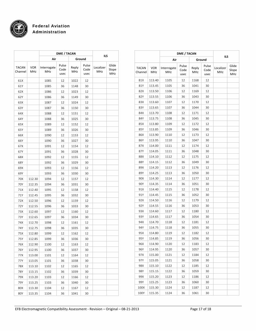
DME / TACAN
ILS Air Ground
TACAN Channel
VOR MHz
Interrogate MHz
Pulse Code usec
Reply MHz
Pulse Code usec
Localizer MHz
Glide Slope MHz
61X 1085 12 1022 12 61Y 1085 36 1148 30 62X 1086 12 1023 12 62Y 1086 36 1149 30 63X 1087 12 1024 12 63Y 1087 36 1150 30 64X 1088 12 1151 12 64Y 1088 36 1025 30 65X 1089 12 1152 12 65Y 1089 36 1026 30 66X 1090 12 1153 12 66Y 1090 36 1027 30 67X 1091 12 1154 12 67Y 1091 36 1028 30 68X 1092 12 1155 12 68Y 1092 36 1029 30 69X 1093 12 1156 12 69Y 1093 36 1030 30 70X 112.30 1094 12 1157 12 70Y 112.35 1094 36 1031 30 71X 112.40 1095 12 1158 12 71Y 112.45 1095 36 1032 30 72X 112.50 1096 12 1159 12 72Y 112.55 1096 36 1033 30 73X 112.60 1097 12 1160 12 73Y 112.65 1097 36 1034 30 74X 112.70 1098 12 1161 12 74Y 112.75 1098 36 1035 30 75X 112.80 1099 12 1162 12 75Y 112.85 1099 36 1036 30 76X 112.90 1100 12 1163 12 76Y 112.95 1100 36 1037 30 77X 113.00 1101 12 1164 12 77Y 113.05 1101 36 1038 30 78X 113.10 1102 12 1165 12 78Y 113.15 1102 36 1039 30 79X 113.20 1103 12 1166 12 79Y 113.25 1103 36 1040 30 80X 113.30 1104 12 1167 12 80Y 113.35 1104 36 1041 30
DME / TACAN
ILS Air Ground
TACAN Channel
VOR MHz
Interrogate MHz
Pulse Code usec
Reply MHz
Pulse Code usec
Localizer MHz
Glide Slope MHz
81X 113.40 1105 12 1168 12 81Y 113.45 1105 36 1041 30 82X 113.50 1106 12 1169 12 82Y 113.55 1106 36 1043 30 83X 113.60 1107 12 1170 12 83Y 113.65 1107 36 1044 30 84X 113.70 1108 12 1171 12 84Y 113.75 1108 36 1045 30 85X 113.80 1109 12 1172 12 85Y 113.85 1109 36 1046 30 86X 113.90 1110 12 1173 12 86Y 113.95 1110 36 1047 30 87X 114.00 1111 12 1174 12 87Y 114.05 1111 36 1048 30 88X 114.10 1112 12 1175 12 88Y 114.15 1112 36 1049 30 89X 114.20 1113 12 1176 12 89Y 114.25 1113 36 1050 30 90X 114.30 1114 12 1177 12 90Y 114.35 1114 36 1051 30 91X 114.40 1115 12 1178 12 91Y 114.45 1115 36 1052 30 92X 114.50 1116 12 1179 12 92Y 114.55 1116 36 1053 30 93X 114.60 1117 12 1180 12 93Y 114.65 1117 36 1054 30 94X 114.70 1118 12 1181 12 94Y 114.75 1118 36 1055 30 95X 114.80 1119 12 1182 12 95Y 114.85 1119 36 1056 30 96X 114.90 1120 12 1183 12 96Y 114.95 1120 36 1057 30 97X 115.00 1121 12 1184 12 97Y 115.05 1121 36 1058 30 98X 115.10 1122 12 1185 12 98Y 115.15 1122 36 1059 30 99X 115.20 1123 12 1186 12 99Y 115.25 1123 36 1060 30
100X 115.30 1124 12 1187 12 100Y 115.35 1124 36 1061 30
Federal Aviation Administration
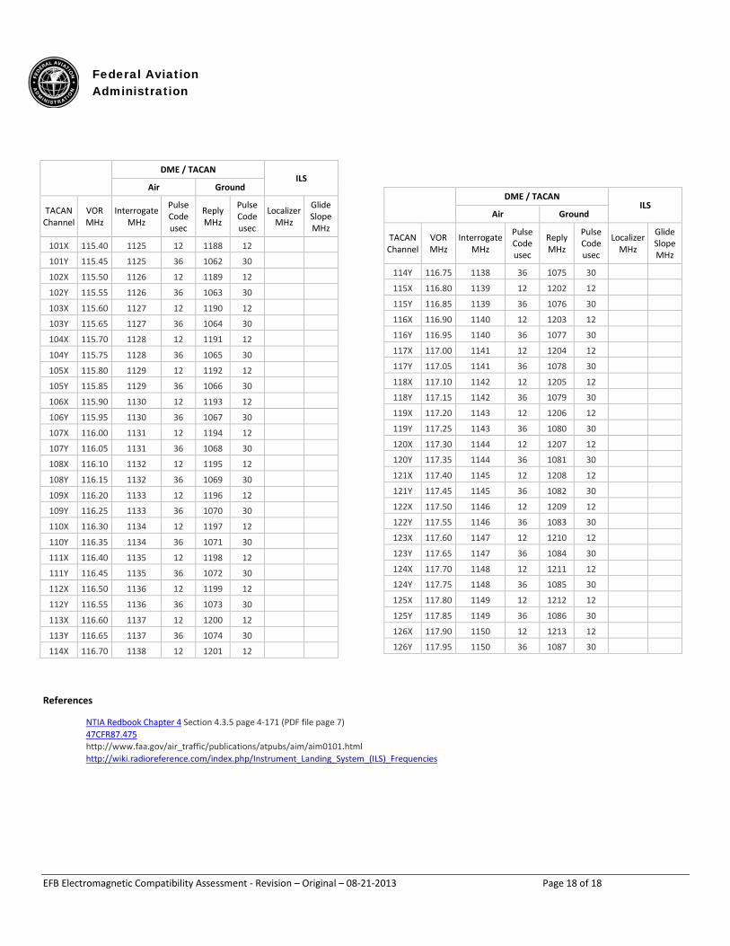
EFB Electromagnetic Compatibility Assessment - Revision – Original – 08-21-2013 Page 18 of 18
DME / TACAN
ILS Air Ground
TACAN Channel
VOR MHz
Interrogate MHz
Pulse Code usec
Reply MHz
Pulse Code usec
Localizer MHz
Glide Slope MHz
101X 115.40 1125 12 1188 12 101Y 115.45 1125 36 1062 30 102X 115.50 1126 12 1189 12 102Y 115.55 1126 36 1063 30 103X 115.60 1127 12 1190 12 103Y 115.65 1127 36 1064 30 104X 115.70 1128 12 1191 12 104Y 115.75 1128 36 1065 30 105X 115.80 1129 12 1192 12 105Y 115.85 1129 36 1066 30 106X 115.90 1130 12 1193 12 106Y 115.95 1130 36 1067 30 107X 116.00 1131 12 1194 12 107Y 116.05 1131 36 1068 30 108X 116.10 1132 12 1195 12 108Y 116.15 1132 36 1069 30 109X 116.20 1133 12 1196 12 109Y 116.25 1133 36 1070 30 110X 116.30 1134 12 1197 12 110Y 116.35 1134 36 1071 30 111X 116.40 1135 12 1198 12 111Y 116.45 1135 36 1072 30 112X 116.50 1136 12 1199 12 112Y 116.55 1136 36 1073 30 113X 116.60 1137 12 1200 12 113Y 116.65 1137 36 1074 30 114X 116.70 1138 12 1201 12
DME / TACAN
ILS Air Ground
TACAN Channel
VOR MHz
Interrogate MHz
Pulse Code usec
Reply MHz
Pulse Code usec
Localizer MHz
Glide Slope MHz
114Y 116.75 1138 36 1075 30 115X 116.80 1139 12 1202 12 115Y 116.85 1139 36 1076 30 116X 116.90 1140 12 1203 12 116Y 116.95 1140 36 1077 30 117X 117.00 1141 12 1204 12 117Y 117.05 1141 36 1078 30 118X 117.10 1142 12 1205 12 118Y 117.15 1142 36 1079 30 119X 117.20 1143 12 1206 12 119Y 117.25 1143 36 1080 30 120X 117.30 1144 12 1207 12 120Y 117.35 1144 36 1081 30 121X 117.40 1145 12 1208 12 121Y 117.45 1145 36 1082 30 122X 117.50 1146 12 1209 12 122Y 117.55 1146 36 1083 30 123X 117.60 1147 12 1210 12 123Y 117.65 1147 36 1084 30 124X 117.70 1148 12 1211 12 124Y 117.75 1148 36 1085 30 125X 117.80 1149 12 1212 12 125Y 117.85 1149 36 1086 30 126X 117.90 1150 12 1213 12 126Y 117.95 1150 36 1087 30
References
NTIA Redbook Chapter 4 Section 4.3.5 page 4-171 (PDF file page 7) 47CFR87.475
http://www.faa.gov/air_traffic/publications/atpubs/aim/aim0101.html http://wiki.radioreference.com/index.php/Instrument_Landing_System_(ILS)_Frequencies