Embed Size (px)
Citation preview
Dra
ft fo
r C
omm
ent
NMRA Technical Note
Layout Command Control® (LCC)
CAN Physical Layer
Feb 8, 2016 TN-9.7.1.1
Adopted as a NMRA Technical NoteThe OpenLCB Standard document appended to this cover sheet has been formally adopted as a NMRA Standard by the NMRA Board of Directors on the date shown in the Adopted column in the Version History table below.
Version HistoryDate Adopted Summary of Changes
Sep 17, 2010 Initial version prepared for Feb-2011 NMRA BoD meeting.
Jun 11, 2012 Aug 2, 2012 Changes from Feb-2011, Jul-2011 & Feb 2012 NMRA BoD meetings and community feedback. Formatting changes to facilitate adding a cover sheet and date disambiguation.
Feb 17, 2015 Feb 20, 2016 Changed title to “Layout Command Control”
Changed document numbering and file name
Feb 8, 2016 Minor grammatical corrections and readability improvements aswell as the following specific changes:
• Changed 4 Physical Interconnection (Normative) to:
◦ change pins 4&5 from "Reserved" to "ALT_L" & "ALT_H"
◦ reduce the maximum voltage ratings down from 100V down to 27V on pins 4&5
• Added new 6 ALT_L / ALT_H section
• Added 6.1 DCC Signal section
• Added 9 Injection Current (Normative) section
5
Submitted for public comment as NMRA Technical Note TN-9.7.1.1
OpenLCB Technical Note
CAN Physical Layer
Feb 8, 2016 Adopted
1 IntroductionThis Technical Note contains informative discussion and background for the corresponding OpenLCB Standard. This Technical Note is not normative in any way.
2 Annotations to the StandardThis section provides background information on corresponding sections of the OpenLCB CAN Standard document. It's expected that the two documents will be read together.
2.1 Introduction
The CAN Physical Layer provides a means by which to transport OpenLCB data over a CAN bus using a standardized mechanical connection and cabling.
2.2 Intended Use
Users can expect to be able to form networks within limitations. For example, reliable operations on a single CAN segment is subject to multiple limitations, including:
• Maximum CAN segment cable length is 1000 ft / 300m
• The max cable length is reduced by 20 ft / 6m for each physical node attached to the segment
• The max cable length is further reduced by double the length of each stub cable attached to the segment
• There may never be less than 1 ft / 30cm of cable between nodes, nor between a stub connection and a node.
This implies that there is a limit of about 48 nodes on a single segment.
These expectations are based on CAN documentation, component-vendor specifications & application notes, and industrial experience with CAN. The intent is to set expectations that can be met essentially all of the time. The Standard does not restrict users from building, or attempting to build, networks that exceed these expectations. Often, OpenLCB CAN layouts that somewhat exceed these expectations will be able to operate reliably.
These expectations are based on UTP/RJ45 wiring of equipment that conforms to the Standard. Wiring and/or equipment that exceeds the Standard may result in being able to reliably build larger networks; alternate wiring or equipment may work well on smaller networks, but may not be able to reach the network sizes listed in that section.
Copyright 2010-2016. All rights reserved. See http://openlcb.org/Licensing.html for license terms. Page 1 of 20 - Feb 8, 2016
5
10
15
20
25

Submitted for public comment as NMRA Technical Note TN-9.7.1.1OpenLCB CAN Physical Layer Technical Note
Manufacturers may want to use CAN transceiver chips with either reduced load, or increased drive capability relative to the CAN specification.
• The CAN specifications require the receiver input impedance Rdiff must be 10k ohms or greater. Transceivers with e.g. 20k ohm input impedance reduce the total bus load and can allow significantly more nodes. They will generally not allow greater maximum lengths.
• The CAN transmitter output drive capability is expressed as a minimum bus resistance of 45 ohms. Bus transmitters with improved drive capability, e.g. 42.5 ohms, can allow significantly more nodes because the bus termination resistance provides much of the total load. Improved transmitters will generally not allow greater maximum lengths.
The Standard permits, but does not require, the use of improved transceivers.
The Standard discusses single CAN segments, and is silent on interconnecting multiple segments. For more discussion of options for interconnection, see the “Repeaters, Bridges and Gateways” section below.
2.3 References and Context
Conformance testing is simplified when it can be done by referring to vendor documentation, rather than requiring specific tests of parameters. The Standard therefore refers to other existing standards, where possible, instead of repeating the information.
2.4 Physical Interconnection
The Standard envisions two basic kinds of nodes: A board with 2 connectors and a box with a pig-tail cable, e.g. a handheld throttle. At the same time, the Standard should not rule out other implementations such as a board with two connectors and three pig-tails for attaching throttles, hence the somewhat complex wording in this section.
The Standard permits providing a terminal block for an alternate wiring of the CAN bus, for example toreduce the cost of small networks, so long as an RJ45 connector or connectors is provided for Standard-compliant wiring. For example, a manufacturer using a terminal block or blocks would provide an adapter board with the two RJ45s which will fit into the terminal block to make a Standard-conformingproduct. This adapter board may have provision for a termination resistors circuit. For mechanical simplicity, a pluggable terminal block could be used to connect the adapter board. As a by-product, if a pluggable RJ45 adapter were used, it would allow the module to be removed without any disturbance to the CAN segment and no need to link the two floating ends of the cable.
The signal names refer back to the signal definitions in the CAN specifications. UTP is unshielded cable, so the CAN_SHIELD conductor is being used as a second conductor for the CAN ground reference, CAN_GND.
The conductor assignments are based on industry practice for RJ45 connectors on CAN networks, c.f. Recommendation CiA 303 (2009) of the CAN in Automation e.V. group.
High-quality RJ45 connections are reliable even after thousands of connections and disconnections. (c.f. An HP survey of RJ45 use as a strain guage connector, a much more demanding application than
Copyright 2010-2016. All rights reserved. See http://openlcb.org/Licensing.html for license terms. Page 2 of 20 - Feb 8, 2016
30
35
40
45
50
55
60
65
Submitted for public comment as NMRA Technical Note TN-9.7.1.1OpenLCB CAN Physical Layer Technical Note
this one1). It's recommended that manufacturers use high-quality RJ45 jacks. They should also recommend that customers assemble CAN segments using high-quality RJ45 cables and plugs. In particular, cables with strain-relief boots and tab protectors will reduce connection problems for e.g. modular layouts.
The assignments of particular wire colors are for information only. These are the wire colors that users will encounter in the two popular ways of wiring commercial cables. When building a product using commercial cable, using one of these two color assignments will reduce confusion, but most OpenLCB CAN users will never need to refer to the wire colors in their cables.
The Standard does not require that all eight conductors be present in cables, but only the four that are minimally necessary for CAN communications. The reserved and power conductors are optional. This is because some low-cost CAT-3 “Ethernet” cables have only those required pairs present. Model railroaders who want to minimize cost, do not need distributed power, and are willing to forego future use of the reserved conductors can use these four-conductor CAT-3 “Ethernet” cables between nodes.
The discussion of connecting in parallel is to make sure that all 8 wires go through a board, whether it'sgot connectors, pig-tail cables or a combination of the two, so long as it's got more than one connectionto other nodes.
The requirement to have all eight conductors present in nodes is so users can add power later, or an updated Standard can define the reserved conductors later, and still use them. The 1A requirement on interconnects is to make sure they're at least as robust as the connectors and cable.
For information on sizing circuit board traces to carry the required interconnection current, please see “IPC-2152 — Specification for Determining Current-carrying Capacity in Printed Board Design, 2009.”
All 8 wires don't have to go through the board if there's only one connection, e.g. a throttle with a single jack or pig-tail cable with plug. In that case, only two pairs are required.
If a conforming device is providing power and has e.g. two jacks, the device can either connect them together and provide a max of 0.5A to both combined, or separately power them up to 0.5A each. This is the only case where a conductor doesn't have to pass through the board as a continuous electrical circuit. Note that this means that the device has to provide power, however; if providing power is an option, not always present, the device should connect conductor 8 across the board to ensure that downstream nodes aren't cut off from power when it's not provided by the device.
Note that the Standard permits, but does not require, connecting the CAN signal ground on conductors 3 & 6 with the PWR_NEG power distribution ground on conductor 7. Power-supplying and power-consuming boards can connect PWR_NEG and the 3/6 grounds to simplify their internal structure. Designers should carefully consider noise immunity, the possibility of ground loops, and voltage offsetswhen doing this. A straight copper connection is within the letter of the requirement. An alternative to connecting them directly is a filtered connection, e.g. a 10 ohm resistor and a small RF choke or ferrite bead choke to isolate high frequency energy on the ground path.
Nodes that need a connection between conductor 7 and conductors 3 & 6 for proper operation are required to connect those conductors to avoid situations where the necessary connection is made on some other node, because that results in hard-to-diagnose bugs as the other node is connected and 1http://www.vtiinstruments.com/Catalog/Technotes/RJ-45_Excels_For_Stria_Gage_Connection.pdf
Copyright 2010-2016. All rights reserved. See http://openlcb.org/Licensing.html for license terms. Page 3 of 20 - Feb 8, 2016
70
75
80
85
90
95
100
105
Submitted for public comment as NMRA Technical Note TN-9.7.1.1OpenLCB CAN Physical Layer Technical Note
disconnected. It's also meant to avoid situations where the remote ground connection results in large ground currents and/or reduced noise margin.
The 27V value in the no-damage requirement for the power connection comes from the S9.1 limitation on track voltage. In the unlikely case that a OpenLCB CAN RJ45 connector is plugged into a telephonesystem, a ringing telephone line can provide as much as 100 volts.
Note that the ISO 11898-2 CAN specification for maximum rating of CAN drivers is -3.0, +16.0 or +32.0 volts. Some CAN transceiver parts have higher maximum input voltage ratings. Implementors should check the specifications of their selected CAN transceivers, and consider whether additional protection against over-voltage damage might be worthwhile if the maximum rating of the component is less than the maximum DCC track voltage.
2.5 Data Transport
A reduced slew rate is preferred to reduce the effect of stubs on the network (c.f. the calculation in section 4.8 of TI SLLA 2702). It's expected that model railroad networks will eventually use stubs to e.g. connect to handheld devices, so it's important to build support for a reasonable number of stubs into the network specification from the start. Note that many off-the-shelf CAN transceiver parts have slew rates greater than 10V/microsecond by default. The recommended value for the slew rate is 4V/microsecond. A design range of 10V/microsecond to 3.5V/microsecond lower limit would allow some manufacturing margin below the 4V/microsecond recommendation.
The Standard only requires that termination meet the CAN requirements, which are limited to the differential total resistance of the terminators. Industry uses some improved termination practices which are discussed in the “Bus Termination” section below.
The Standard is silent on the use of specific CAN frame formats or features.
2.6 ALT_L / ALT_H
After meeting the requirements to carry CAN data and power, there remains a spare conductor pair available for use. The use of these conductors is not fixed, and additional uses may be defined in the future. It is also possible that a given OpenLCB CAN installation may choose to take advantage of more than one of the additional uses. This is allowed, so long as the two uses are not electrically tied toone another. In other words, the OpenLCB ALT_L / ALT_H conductor path would need to be broken between differing uses.
Several methods may be used to break the conduction path of ALT_L / ALT_H, and no one method is prescribed by the standard. For example:
1. A custom cable can be made that does not carry conductors 4 & 5
2. A node manufacturer might choose to provide a node with jumpers for passing conductors 4 & 5 through the node
2http://focus.ti.com/lit/an/slla270/slla270.pdf
Copyright 2010-2016. All rights reserved. See http://openlcb.org/Licensing.html for license terms. Page 4 of 20 - Feb 8, 2016
110
115
120
125
130
135
140
5
Submitted for public comment as NMRA Technical Note TN-9.7.1.1OpenLCB CAN Physical Layer Technical Note
Though OpenLCB cabling is not required to carry conductors 4 & 5, it is important to note that all nodes that do not use conductors 4 & 5 must still pass these signals through their node so as to not disturb the conduction path.
2.6.1 DCC Signal
For this use case, conductors 4 & 5 carry the DCC signal typically sourced by a DCC command station and typically consumed by a DCC power station, commonly known as a DCC Booster. Either one of the signaling methods mentioned by the NMRA standard S-9.1.2 may be used:
• Opto-isolated (Current) Interface
• Driver/Receiver (Voltage) Interface
It is important to note that in order to be compliant to the CAN Physical Standard, an OpenLCB node that sources or consumes the DCC signal must also conform to the requirements in NMRA standard S-9.1.2. This includes:
1. Labeling requirements which identify the type of signal(s) that a command station is capable ofsourcing as well as the type of signal(s) that a power station is capable of consuming.
2. Current limits on what source nodes are allowed to output. This requirement makes the ALT_L/ALT_H unsuitable as a low impedance return path for current between power stations.
3. Current limits on what consumer nodes are allowed to consume. This requirement makes the ALT_L/ALT_H unsuitable as a low impedance return path for current between power stations.
4. Consumers must provide a user accessible connection for the common side of their DC power supplies. The intent is provide a low impedance return path for current between power stationswhen a load is transitioning from one power station to another. This is sometimes referred to as a common ground. The intent is to prevent large asymmetric currents from traveling across the CAN Physical Interconnection conductors, which could lead to exceeding their current carrying capacity and producing unwanted hazards.
The DCC signal use case of conductors 4 & 5 is intended to be used such that there is exactly one DCCsignal source and one or more DCC signal consumers.
It is possible, and relatively straight forward, for a DCC source to produce a signal that is voltage level compatible with both signaling methods outlined in NMRA standard S-9.1.2. Manufacturers of DCC signal source and consumer nodes are encouraged, but not required, to consider these points when producing their products.
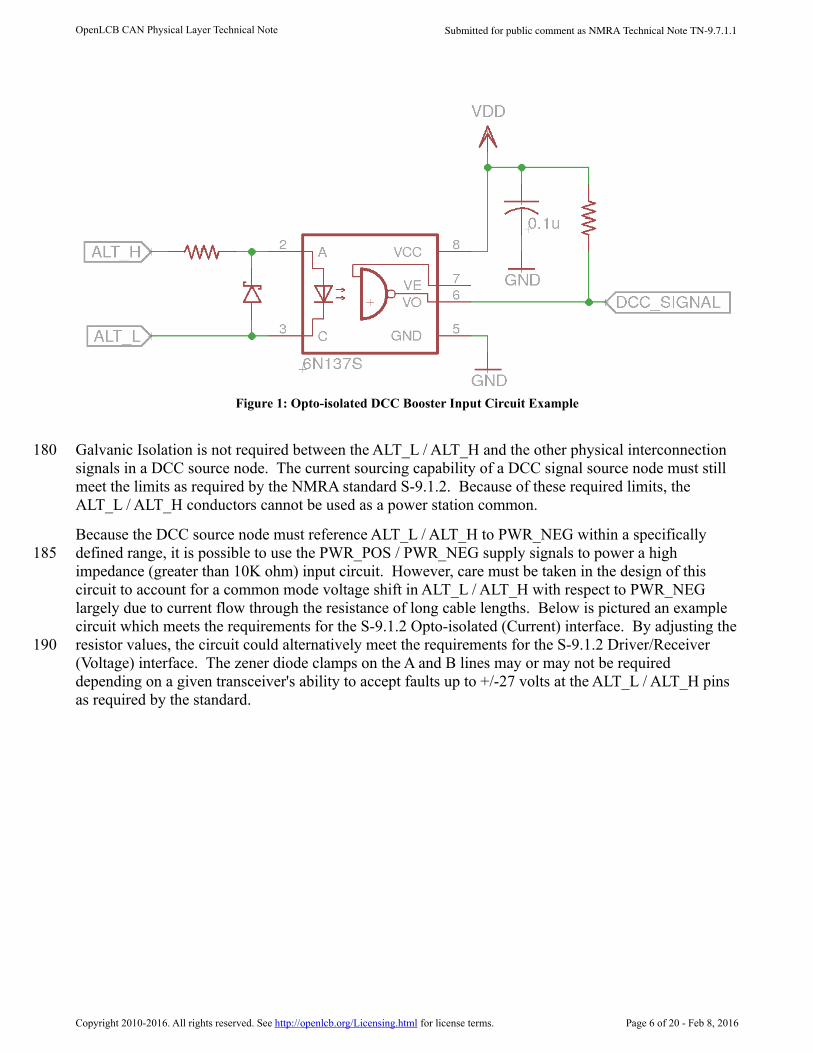
It is strongly encouraged that manufacturers consider galvanic isolation, especially in DCC signal consumer nodes that have a high current potential which exceeds the limits of the CAN Physical Interconnection's capabilities. Galvanic isolation on conductors 1, 2, 3, 6, 7, and 8 from the high current potential portion of the DCC signal consumer's circuitry should also be considered, though not explicitly required, if these signals are used. Below is pictured an example circuit that is commonly used in many existing DCC power stations which meets these requirements for the S-9.1.2 Opto-isolated (Current) interface.
Copyright 2010-2016. All rights reserved. See http://openlcb.org/Licensing.html for license terms. Page 5 of 20 - Feb 8, 2016
145
150
155
160
165
170
175
Submitted for public comment as NMRA Technical Note TN-9.7.1.1OpenLCB CAN Physical Layer Technical Note
Galvanic Isolation is not required between the ALT_L / ALT_H and the other physical interconnection signals in a DCC source node. The current sourcing capability of a DCC signal source node must still meet the limits as required by the NMRA standard S-9.1.2. Because of these required limits, the ALT_L / ALT_H conductors cannot be used as a power station common.
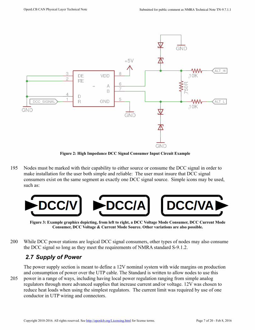
Because the DCC source node must reference ALT_L / ALT_H to PWR_NEG within a specifically defined range, it is possible to use the PWR_POS / PWR_NEG supply signals to power a high impedance (greater than 10K ohm) input circuit. However, care must be taken in the design of this circuit to account for a common mode voltage shift in ALT_L / ALT_H with respect to PWR_NEG largely due to current flow through the resistance of long cable lengths. Below is pictured an example circuit which meets the requirements for the S-9.1.2 Opto-isolated (Current) interface. By adjusting theresistor values, the circuit could alternatively meet the requirements for the S-9.1.2 Driver/Receiver (Voltage) interface. The zener diode clamps on the A and B lines may or may not be required depending on a given transceiver's ability to accept faults up to +/-27 volts at the ALT_L / ALT_H pins as required by the standard.
Copyright 2010-2016. All rights reserved. See http://openlcb.org/Licensing.html for license terms. Page 6 of 20 - Feb 8, 2016
Figure 1: Opto-isolated DCC Booster Input Circuit Example
180
185
190
Submitted for public comment as NMRA Technical Note TN-9.7.1.1OpenLCB CAN Physical Layer Technical Note
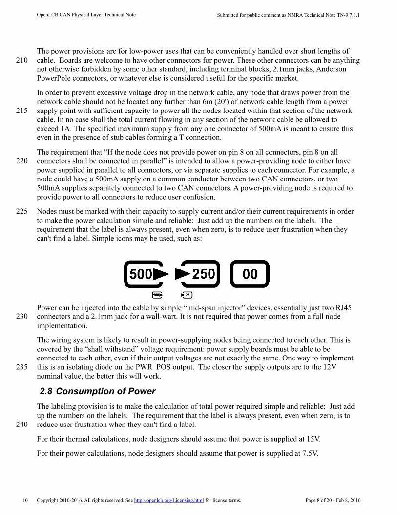
Nodes must be marked with their capability to either source or consume the DCC signal in order to make installation for the user both simple and reliable: The user must insure that DCC signal consumers exist on the same segment as exactly one DCC signal source. Simple icons may be used, such as:
While DCC power stations are logical DCC signal consumers, other types of nodes may also consume the DCC signal so long as they meet the requirements of NMRA standard S-9.1.2.
2.7 Supply of Power
The power supply section is meant to define a 12V nominal system with wide margins on production and consumption of power over the UTP cable. The Standard is written to allow nodes to use this power in a range of ways, including having local power regulation ranging from simple analog regulators through more advanced supplies that increase current and/or voltage. 12V was chosen to reduce heat loads when using the simplest regulators. The current limit was required by use of one conductor in UTP wiring and connectors.
Copyright 2010-2016. All rights reserved. See http://openlcb.org/Licensing.html for license terms. Page 7 of 20 - Feb 8, 2016
Figure 2: High Impedance DCC Signal Consumer Input Circuit Example
Figure 3: Example graphics depicting, from left to right, a DCC Voltage Mode Consumer, DCC Current ModeConsumer, DCC Voltage & Current Mode Source. Other variations are also possible.
195
200
205
Submitted for public comment as NMRA Technical Note TN-9.7.1.1OpenLCB CAN Physical Layer Technical Note
The power provisions are for low-power uses that can be conveniently handled over short lengths of cable. Boards are welcome to have other connectors for power. These other connectors can be anythingnot otherwise forbidden by some other standard, including terminal blocks, 2.1mm jacks, Anderson PowerPole connectors, or whatever else is considered useful for the specific market.
In order to prevent excessive voltage drop in the network cable, any node that draws power from the network cable should not be located any further than 6m (20') of network cable length from a power supply point with sufficient capacity to power all the nodes located within that section of the network cable. In no case shall the total current flowing in any section of the network cable be allowed to exceed 1A. The specified maximum supply from any one connector of 500mA is meant to ensure this even in the presence of stub cables forming a T connection.
The requirement that “If the node does not provide power on pin 8 on all connectors, pin 8 on all connectors shall be connected in parallel” is intended to allow a power-providing node to either have power supplied in parallel to all connectors, or via separate supplies to each connector. For example, a node could have a 500mA supply on a common conductor between two CAN connectors, or two 500mA supplies separately connected to two CAN connectors. A power-providing node is required to provide power to all connectors to reduce user confusion.
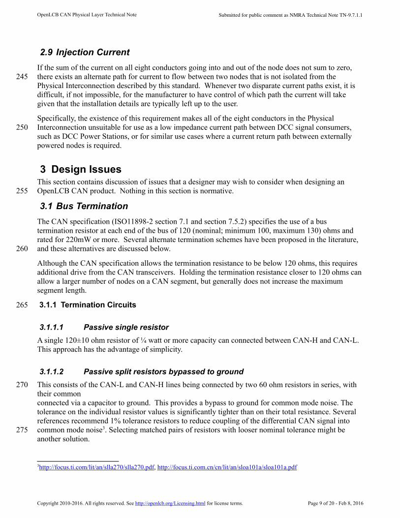
Nodes must be marked with their capacity to supply current and/or their current requirements in order to make the power calculation simple and reliable: Just add up the numbers on the labels. The requirement that the label is always present, even when zero, is to reduce user frustration when they can't find a label. Simple icons may be used, such as:
Power can be injected into the cable by simple “mid-span injector” devices, essentially just two RJ45 connectors and a 2.1mm jack for a wall-wart. It is not required that power comes from a full node implementation.
The wiring system is likely to result in power-supplying nodes being connected to each other. This is covered by the “shall withstand” voltage requirement: power supply boards must be able to be connected to each other, even if their output voltages are not exactly the same. One way to implement this is an isolating diode on the PWR_POS output. The closer the supply outputs are to the 12V nominal value, the better this will work.
2.8 Consumption of Power
The labeling provision is to make the calculation of total power required simple and reliable: Just add up the numbers on the labels. The requirement that the label is always present, even when zero, is to reduce user frustration when they can't find a label.
For their thermal calculations, node designers should assume that power is supplied at 15V.
For their power calculations, node designers should assume that power is supplied at 7.5V.
Copyright 2010-2016. All rights reserved. See http://openlcb.org/Licensing.html for license terms. Page 8 of 20 - Feb 8, 2016
210
215
220
225
230
235
240
10
Submitted for public comment as NMRA Technical Note TN-9.7.1.1OpenLCB CAN Physical Layer Technical Note
2.9 Injection Current
If the sum of the current on all eight conductors going into and out of the node does not sum to zero, there exists an alternate path for current to flow between two nodes that is not isolated from the Physical Interconnection described by this standard. Whenever two disparate current paths exist, it is difficult, if not impossible, for the manufacturer to have control of which path the current will take given that the installation details are typically left up to the user.
Specifically, the existence of this requirement makes all of the eight conductors in the Physical Interconnection unsuitable for use as a low impedance current path between DCC signal consumers, such as DCC Power Stations, or for similar use cases where a current return path between externally powered nodes is required.
3 Design IssuesThis section contains discussion of issues that a designer may wish to consider when designing an OpenLCB CAN product. Nothing in this section is normative.
3.1 Bus Termination
The CAN specification (ISO11898-2 section 7.1 and section 7.5.2) specifies the use of a bus termination resistor at each end of the bus of 120 (nominal; minimum 100, maximum 130) ohms and rated for 220mW or more. Several alternate termination schemes have been proposed in the literature,and these alternatives are discussed below.
Although the CAN specification allows the termination resistance to be below 120 ohms, this requires additional drive from the CAN transceivers. Holding the termination resistance closer to 120 ohms canallow a larger number of nodes on a CAN segment, but generally does not increase the maximum segment length.
3.1.1 Termination Circuits
3.1.1.1 Passive single resistor
A single 120±10 ohm resistor of ¼ watt or more capacity can connected between CAN-H and CAN-L. This approach has the advantage of simplicity.
3.1.1.2 Passive split resistors bypassed to ground
This consists of the CAN-L and CAN-H lines being connected by two 60 ohm resistors in series, with their commonconnected via a capacitor to ground. This provides a bypass to ground for common mode noise. The tolerance on the individual resistor values is significantly tighter than on their total resistance. Several references recommend 1% tolerance resistors to reduce coupling of the differential CAN signal into common mode noise3. Selecting matched pairs of resistors with looser nominal tolerance might be another solution.
3http://focus.ti.com/lit/an/slla270/slla270.pdf, h ttp://focus.ti.com.cn/cn/lit/an/sloa101a/sloa101a.pdf
Copyright 2010-2016. All rights reserved. See http://openlcb.org/Licensing.html for license terms. Page 9 of 20 - Feb 8, 2016
245
250
255
260
265
270
275
Submitted for public comment as NMRA Technical Note TN-9.7.1.1OpenLCB CAN Physical Layer Technical Note
3.1.1.3 Biased split termination
As in (3.1.1.2), but the common of the resistors is also tied to a fixed voltage. This can be to nominal 2.5V via a voltage divider4, or by using a voltage reference5. If there is a significant offset of ground between two nodes, then this offset will be transmitted to the CAN lines with consequent degradation of common-mode rejection.
3.1.1.4 Active termination
This termination is accomplished by using active elements, such as transistors or op-amps, to actively drive the bus to its proper state. Because of the recessive component of the ISO 11898-2 CAN signal, this form of termination is not appropriate.
3.1.1.5 Distributed termination
This technique requires a fixed number of custom-impedance nodes, and is therefore not suitable for model railroad applications that are based on user-specific ad-hoc networks made from standard components.
3.1.2 Terminator Placement
Termination can be supplied as an on-board option, or as a terminator housed within an RJ45 plug, or as a separate terminator device, depending on the preferences of the manufacturer andusers.
Using plug-resident terminators would seem to provide the maximum flexibility, but it may be difficult to build a split terminator into a RJ45 plug.
If on-board terminators are provided, the Standard requires it be possible to enable or disable them depending on where the node is installed on the CAN segment. Termination should only occur at the two distant ends of the bus. Termination in the middle of a significant-length CAN bus is very disruptive because it causes reflections. The one downside to on-board termination is that it makes it much easier to have multiple terminators (customers think more must be good, and mistakenly turn them all on). It's required that nodes be shipped with on-board terminators disabled to reduce the chance that a termination load will be attached in the middle of the segment. Note that ISO11898-2 states “The locating of the termination within a CAN node should be avoided because the bus lines losetermination if this node is disconnected from the bus line.” (Section 5.2.1) and “It is not recommended to integrate the termination into a CAN node.” (Section 7.1)
Manufacturers may want to provide a special termination node to provide some indication of bus health as well as providing termination. Industrial diagnostic equipment provides some examples of what can be done6.
4http://ww1.microchip.com/downloads/en/AppNotes/00228a.pdf
5http://focus.ti.com.cn/cn/lit/an/sloa101a/sloa101a.pdf
http://www.nxp.com/documents/application_note/AN10211.pdf
6http://www.microchip.com/stellent/idcplg?IdcService=SS_GET_PAGE&nodeId=1406&dDocName=en546534
http://www.ixxat.com/cancheck_en.html?markierung=cancheck
Copyright 2010-2016. All rights reserved. See http://openlcb.org/Licensing.html for license terms. Page 10 of 20 - Feb 8, 2016
280
285
290
295
300
305
15
Submitted for public comment as NMRA Technical Note TN-9.7.1.1OpenLCB CAN Physical Layer Technical Note
3.2 EMC Management and Noise Immunity
Electro-Magnetic Compatibility (EMC) refers to ensuring that a system, e.g. a CAN bus, does not cause interference with other systems. CAN is a robust signaling method developed for use in the difficult environment of automobiles. Issues of EMC, noise immunity, etc have been discussed in numerous vendor application notes7.
See also the “References” section below.
3.2.1 Chokes
A series choke or transformer can improve the noise immunity of a CAN transceiver. The Standard permits the use of one, but doesn't require it. The advantages and disadvantages of including one are discussed in the NXP (Philips) and Texas Instruments application notes referenced above. See also the footnote below8.
Typical parts are the TDK ZJYS81RS-2PL51(T)-G01 and the ZJYS51-2PT.
3.2.2 ESD and surge protection
The CAN Standard requires a certain level of over-voltage protection in CAN transceivers. External parts may be used to provide additional protection. The Standard is silent on this, requiring nothing beyond the CAN Standard, and OpenLCB makes no recommendations. Manufacturers may want to consider including additional protection, but have to balance the costs and benefits of that. For a longer discussion, see:
J. Lepkowski and B. Wolfe, ON Semiconductor: EMI/ESD protection solutions for the CAN bus; CANin Automation, iCC 20059
For an example of external protection, see the footnote below10.
http://www.ixxat.com/can_bus_tester_cbt_en.html
http://www.can-cia.org/pg/can/categories/generic_tool/physical/none/none/index.html
7http://www.nxp.com/documents/application_note/AN10211.pdf
http://focus.ti.com/lit/an/slla270/slla270.pdf
8http://www.ti.com/lit/an/slla271/slla271.pdf
9www.can-cia.org/fileadmin/cia/files/icc/10/cia_paper_lepkowski.pdf
10http://www.nxp.com/documents/data_sheet/PESD1CAN.pdf
Copyright 2010-2016. All rights reserved. See http://openlcb.org/Licensing.html for license terms. Page 11 of 20 - Feb 8, 2016
310
315
320
325
330
20
25
Submitted for public comment as NMRA Technical Note TN-9.7.1.1OpenLCB CAN Physical Layer Technical Note
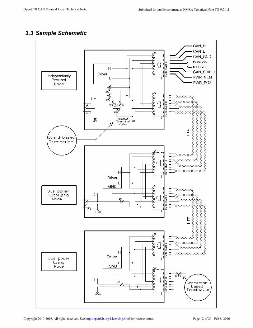
3.3 Sample Schematic
Copyright 2010-2016. All rights reserved. See http://openlcb.org/Licensing.html for license terms. Page 12 of 20 - Feb 8, 2016
Submitted for public comment as NMRA Technical Note TN-9.7.1.1OpenLCB CAN Physical Layer Technical Note
The following informative schematic is a sample of various possible design choices, and not normative in any way.
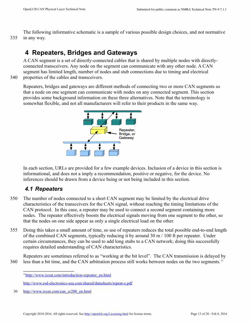
4 Repeaters, Bridges and GatewaysA CAN segment is a set of directly-connected cables that is shared by multiple nodes with directly-connected transceivers. Any node on the segment can communicate with any other node. A CAN segment has limited length, number of nodes and stub connections due to timing and electrical properties of the cables and transceivers.
Repeaters, bridges and gateways are different methods of connecting two or more CAN segments so that a node on one segment can communicate with nodes on any connected segment. This section provides some background information on these three alternatives. Note that the terminology is somewhat flexible, and not all manufacturers will refer to their products in the same way.
In each section, URLs are provided for a few example devices. Inclusion of a device in this section is informational, and does not a imply a recommendation, positive or negative, for the device. No inferences should be drawn from a device being or not being included in this section.
4.1 Repeaters
The number of nodes connected to a short CAN segment may be limited by the electrical drive characteristics of the transceivers for the CAN signal, without reaching the timing limitations of the CAN protocol. In this case, a repeater may be used to connect a second segment containing more nodes. The repeater effectively boosts the electrical signals moving from one segment to the other, so that the nodes on one side appear as only a single electrical load on the other.
Doing this takes a small amount of time, so use of repeaters reduces the total possible end-to-end lengthof the combined CAN segments, typically reducing it by around 30 m / 100 ft per repeater. Under certain circumstances, they can be used to add long stubs to a CAN network; doing this successfully requires detailed understanding of CAN characteristics.
Repeaters are sometimes referred to as “working at the bit level”. The CAN transmission is delayed byless than a bit time, and the CAN arbitration process still works between nodes on the two segments.11
11http://www.ixxat.com/introduction-repeater_en.html
http://www.esd-electronics-usa.com/shared/datasheets/repeat-e.pdf
http://www.ixxat.com/can_cr200_en.html
Copyright 2010-2016. All rights reserved. See http://openlcb.org/Licensing.html for license terms. Page 13 of 20 - Feb 8, 2016
335
340
350
355
360
30
Submitted for public comment as NMRA Technical Note TN-9.7.1.1OpenLCB CAN Physical Layer Technical Note
4.2 Bridges
A bridge looks like an independent CAN node on each of two or more CAN segments, receiving frames on a segment and sending them independently on the others. As such, it allows connection of two or more full size, full node-count CAN segments.
Bridges are sometimes referred to as “working at the frame level”. The CAN transmission is delayed by much more than a bit time, usually a frame time or longer.
The CAN arbitration process takes place on each segment independently, and is not shared between theseparate segments; frames will appear in different order on the various segments. RTR frames generallycannot be used across bridges. The protocol(s) running on the CAN segments must be compatible with these constraints if bridges are to be used.
Because bridges break the timing connection between the connected segments, they can also be used for remote connections via non-CAN cables, wireless, etc. In this case, a bridge device is usually used at each end of the remote link, and the protocol between the two devices is specific to the CAN bridge function12.
4.3 Gateways
Gateways connect a CAN segment to another communication technology, such as IP over wireless, Ethernet or some other. In the process, they may reformat or translate the CAN frames as needed. For example, a USB-CAN adapter may convert the CAN frame bytes into some form of human-readable text.
This reformatting may be independent of the CAN frame content information, or specific to some protocol that defines meaning for the CAN frames13.
5 ReferencesThis section provides references, and when possible URLs, that may be of use to OpenLCB-CAN implementors.
12http://www.ixxat.com/introduction_bridges_en.html
http://www.ieee-icnp.org/1996/papers/1996-21.pdf
http://doi.ieeecomputersociety.org/10.1109/ISPAN.1996.509033
http://www.ixxat.com/can_bridge_en.html
http://www.wrcakron.com/devicenet/CAN_Bus_Applications.pdf
http://www.matric.com/canbridge.html
13http://www.phytec.com/products/can/pc-can-interfaces/CAN-Ethernet-Gateway.html
http://news.thomasnet.com/fullstory/Gateway-converts-from-CAN-into-Ethernet-529941
http://www.icpdas-usa.com/products.php?PID=3075
Copyright 2010-2016. All rights reserved. See http://openlcb.org/Licensing.html for license terms. Page 14 of 20 - Feb 8, 2016
365
370
375
380
35
40
Submitted for public comment as NMRA Technical Note TN-9.7.1.1OpenLCB CAN Physical Layer Technical Note
5.1 Standards
The OpenLCB CAN Physical Layer Standard references ISO 11898-1 and ISO 11898-2 for CAN specifications. The ISO14 sells PDF and paper copies of these. Copies can generally be found in engineering libraries15.
Note that ISO 11898-3, 11898-4 and 11898-5 specify different variants of the CAN standard that are not relevant to OpenLCB CAN-compliant implementations. The original 1995 Bosch CAN standard, which can be found online, is similar to ISO 11898-1 and -2, but not identical.
The OpenLCB CAN Physical Layer Standard references TIA/EIA-568-B or the successor TIA/EIA- 568-C for unshielded twisted pair (UTP) cable, and TIA-968-A for RJ45 modular plugs and jacks. The TIA16 sells PDF and paper copies of these. Copies can generally be found in engineering libraries.
5.2 Books
This section is an informal list of books that may or may not be useful for people building OpenLCB CAN devices. The brief reviews are just opinion, and you should make up your own mind about the correctness and usefulness of the book.
5.2.1 Recommended
“Controller Area Network: Basics, Protocols, Chips and Applications”, Prof. Dr.-Ing. K. Etschberger, IXXAT Press, Weingarten, Germany 2001 – a little dated now, but has excellent discussions of theory, particularly for complex networks.
"Embedded Networking with CAN and CANopen", Pfeiffer, Ayre and Keydel, Copperhill Technologies, 2008 – generally considered the gold standard in CAN books.
“A Comprehensible Guide to Controller Area Network”, Wilfried Voss, Copperhill Technologies, 2005
“Multiplexed Networks for Embedded Systems”, Dominique Paret, Wiley, 2007 – good coverage of CAN through first half of volume, including protocol and physical layer issues.
5.2.2 Not Recommended
“Designing Embedded Systems with PIC Microcontrollers”, Tim Wilmhurst, Newnes (Elsevier), 2010 – very brief coverage of CAN issues on pages 581 through 586.
“Embedded Systems Design and Applications with the 68HC12 and HCS12”, S.F. Barret and D.J. Pack, Pearson Prentice Hall, 2005 – limited coverage of CAN from pages 595 through 600, with coverage of the details of the specific msCAN12 controller through page 634. Of limited value unless one is writing a low-level library for that controller.
14http://www.iso.org
15http://www.iso.org/iso/iso_catalogue/catalogue_tc/catalogue_detail.htm?csnumber=33422
http://www.iso.org/iso/iso_catalogue/catalogue_tc/catalogue_detail.htm?csnumber=33423
16http://www.tiaonline.org
Copyright 2010-2016. All rights reserved. See http://openlcb.org/Licensing.html for license terms. Page 15 of 20 - Feb 8, 2016
385
390
395
400
405
410
45
Submitted for public comment as NMRA Technical Note TN-9.7.1.1OpenLCB CAN Physical Layer Technical Note
5.3 Application Notes
A number of component manufacturers have written application notes that may be useful to OpenLCB CAN developers. A list is provided here for reference, but note that none of these are normative; for specific values, etc, please refer to the standards listed above.
5.3.1 Anixter
“ANSI/TIA/EIA-568-B Standards Reference Guide”17
5.3.2 Mohawk.com
“ANSI/TIA/EIA-568-B (B.1, B.2 and B.3) Commercial Building Telecommunications Cabling Standard”18
5.3.3 Microchip Corp
AN713 “Controller Area Network (CAN) Basics”19
AN228 “A CAN Physical Layer Discussion”20
AN853 “PIC18XXX8 CAN Driver with Prioritized Transmit Buffer”21
5.3.4 ON Semiconductor
AND8376/D “AMIS-30660/42000 - Topology Aspects of a High-Speed CAN Bus”22
5.3.5 NXP Electronics (Philips)
AN96116 “PCA82C250 / 251 CAN Transceiver”23
AN10211 “TJA1040 high speed CAN transceiver”24
5.3.6 Texas Instruments
Analog Applications Journal, August 1999, TI SLYT197 “TIA/EIA-568A Category 5 cables in low-voltage differential signaling (LVDS)”25
Application Report SLOA101A “Introduction to the Controller Area Network (CAN)”26
17https://www.anixter.com/content/dam/Anixter/Guide/12H0001X00-Anixter-Standard-Ref-Guide-ECS-US.pdf
18http://www.mohawk-cable.com/support/ansi-tia-eia-568-b.html
19http://ww1.microchip.com/downloads/en/AppNotes/00713a.pdf
20http://ww1.microchip.com/downloads/en/AppNotes/00228a.pdf
21http://ww1.microchip.com/downloads/en/AppNotes/00853a.pdf
22http://www.onsemi.com/pub_link/Collateral/AND8376-D.PDF
23http://www.nxp.com/documents/application_note/AN96116.pdf
24http://www.nxp.com/documents/application_note/AN10211.pdf
25http://focus.ti.com/lit/an/slyt197/slyt197.pdf
26http://focus.ti.com.cn/cn/lit/an/sloa101a/sloa101a.pdf
Copyright 2010-2016. All rights reserved. See http://openlcb.org/Licensing.html for license terms. Page 16 of 20 - Feb 8, 2016
415
420
425
430
435
50
55
Submitted for public comment as NMRA Technical Note TN-9.7.1.1OpenLCB CAN Physical Layer Technical Note
Application Report SLLA270 “Controller Area Network Physical Layer Requirements”27
Application Report SLLA298B “Isolated CAN Reference Design”28
Application Report SLOU262 “Isolated CAN Transceiver EVM”29
Application Report SLLA271 “Common Mode Chokes in CAN Networks: Source of Unexpected Transients”30
Analog Applications Journal, 3Q 2006, TI SLYT249 “Improved CAN network security with TI’s SN65HVD1050 transceiver”31
5.4 Component data sheets
This section lists component data sheets that may be of value to the OpenLCB CAN implementor. Inclusion of a component data sheet in this section is informational, and does not a imply a recommendation, positive or negative, for the component or data sheet. No inferences should be drawn from a component data sheet being or not being included in this section.
5.4.1 Microchip
MCP2551 High-Speed CAN Transceiver32
MCP2561, MCP2562 High-Speed CAN Transceiver33
MCP2515 Stand-Alone CAN Controller With SPI Interface34
5.4.2 NXP Electronics (Philips)
PCA82C250 CAN controller interface35
TJA1043 High-speed CAN transceiver36
PESD1CAN CAN bus ESD protection diode37
27http://focus.ti.com/lit/an/slla270/slla270.pdf
28http://focus.ti.com/lit/an/slla298b/slla298b.pdf
29http://focus.tij.co.jp/jp/lit/ug/slou262/slou262.pdf
30http://www.ti.com/lit/an/slla271/slla271.pdf
31http://focus.ti.com/lit/an/slyt249/slyt249.pdf
32http://ww1.microchip.com/downloads/en/DeviceDoc/21667f.pdf
33http://ww1.microchip.com/downloads/en/DeviceDoc/20005167C.pdf
34http://ww1.microchip.com/downloads/en/DeviceDoc/21801e.pdf
35http://www.nxp.com/documents/data_sheet/PCA82C250.pdf
36http://www.nxp.com/documents/data_sheet/TJA1043.pdf
37http://www.nxp.com/documents/data_sheet/PESD1CAN.pdf
Copyright 2010-2016. All rights reserved. See http://openlcb.org/Licensing.html for license terms. Page 17 of 20 - Feb 8, 2016
440
445
450
455
60
65
Submitted for public comment as NMRA Technical Note TN-9.7.1.1OpenLCB CAN Physical Layer Technical Note
5.4.3 STMicroelectronics
L9615 transceiver38
5.4.4 Texas Instruments
ISO1050 Isolated CAN Transceiver39
SN55HVD251, SN65HVD251 Industrial CAN Transceiver40
SN65HVD1050 EMC Optimized CAN Transceiver41
SN55HVD230, SN55HVD231, SN55HVD232 3.3-V CAN Transceivers42
5.5 Tools
This section lists tools and diagnostic equipment that may be of value to the OpenLCB CAN implementor. Inclusion of an item in this section is informational, and does not a imply a recommendation, positive or negative, for the item. No inferences should be drawn from an item being or not being included in this section.
5.5.1 Microchip
CAN BUS Analyzer Tool “simple to use low cost CAN bus monitor”43
5.5.2 IXAAT
CANcheck “Installation tester for CAN networks”44
CAN Bus Tester “Diagnostic tool for long-term monitoring of CAN bus systems”45
38http://www.st.com/st-web-ui/static/active/en/resource/technical/document/datasheet/CD00001375.pdf
39http://focus.ti.com/lit/ds/symlink/iso1050.pdf
40http://focus.ti.com/lit/ds/symlink/sn55hvd251.pdf
41http://focus.ti.com/lit/ds/symlink/sn65hvd1050.pdf
42http://www.ti.com/lit/ds/symlink/sn65hvd230.pdf
43h ttp://www.microchip.com/stellent/idcplg?IdcService=SS_GET_PAGE&nodeId=1406&dDocName=en546534
44http://www.ixxat.com/cancheck_en.html?markierung=cancheck
45http://www.ixxat.com/can_bus_tester_cbt_en.html
Copyright 2010-2016. All rights reserved. See http://openlcb.org/Licensing.html for license terms. Page 18 of 20 - Feb 8, 2016
460
465
470
70
75

Submitted for public comment as NMRA Technical Note TN-9.7.1.1OpenLCB CAN Physical Layer Technical Note
Table of Contents 1 Introduction............................................................................................................................................ 1
2 Annotations to the Standard................................................................................................................... 1
2.1 Introduction.................................................................................................................................... 1
2.2 Intended Use...................................................................................................................................1
2.3 References and Context..................................................................................................................2
2.4 Physical Interconnection................................................................................................................ 2
2.5 Data Transport................................................................................................................................ 4
2.6 ALT_L / ALT_H............................................................................................................................. 4
2.6.1 DCC Signal.............................................................................................................................5
2.7 Supply of Power............................................................................................................................. 7
2.8 Consumption of Power...................................................................................................................8
2.9 Injection Current.............................................................................................................................9
3 Design Issues..........................................................................................................................................9
3.1 Bus Termination............................................................................................................................. 9
3.1.1 Termination Circuits............................................................................................................... 9
3.1.1.1 Passive single resistor..................................................................................................... 9
3.1.1.2 Passive split resistors bypassed to ground...................................................................... 9
3.1.1.3 Biased split termination................................................................................................ 10
3.1.1.4 Active termination.........................................................................................................10
3.1.1.5 Distributed termination................................................................................................. 10
3.1.2 Terminator Placement........................................................................................................... 10
3.2 EMC Management and Noise Immunity......................................................................................11
3.2.1 Chokes.................................................................................................................................. 11
3.2.2 ESD and surge protection..................................................................................................... 11
3.3 Sample Schematic........................................................................................................................ 12
4 Repeaters, Bridges and Gateways........................................................................................................ 13
Copyright 2010-2016. All rights reserved. See http://openlcb.org/Licensing.html for license terms. Page 19 of 20 - Feb 8, 2016
Submitted for public comment as NMRA Technical Note TN-9.7.1.1OpenLCB CAN Physical Layer Technical Note
4.1 Repeaters...................................................................................................................................... 13
4.2 Bridges..........................................................................................................................................14
4.3 Gateways...................................................................................................................................... 14
5 References............................................................................................................................................ 14
5.1 Standards...................................................................................................................................... 15
5.2 Books............................................................................................................................................15
5.2.1 Recommended...................................................................................................................... 15
5.2.2 Not Recommended............................................................................................................... 15
5.3 Application Notes......................................................................................................................... 16
5.3.1 Anixter.................................................................................................................................. 16
5.3.2 Mohawk.com........................................................................................................................ 16
5.3.3 Microchip Corp.....................................................................................................................16
5.3.4 ON Semiconductor............................................................................................................... 16
5.3.5 NXP Electronics (Philips).....................................................................................................16
5.3.6 Texas Instruments................................................................................................................. 16
5.4 Component data sheets.................................................................................................................17
5.4.1 Microchip..............................................................................................................................17
5.4.2 NXP Electronics (Philips).....................................................................................................17
5.4.3 STMicroelectronics...............................................................................................................18
5.4.4 Texas Instruments................................................................................................................. 18
5.5 Tools............................................................................................................................................. 18
5.5.1 Microchip..............................................................................................................................18
5.5.2 IXAAT.................................................................................................................................. 18
Copyright 2010-2016. All rights reserved. See http://openlcb.org/Licensing.html for license terms. Page 20 of 20 - Feb 8, 2016
475
80

![[RTF] 25 f w Tn William 24 m w /200 Tn Alfred 18 m w Tn 807/809 Albert ROUGHMONT 38 m w farmer 1200/820 Switzerland Rebecca 38 f w Tn Isabell 11 f w Tn Abercrombe 8 m w Tn Emaline](https://img.pdfslide.us/doc/110x75/5b4743837f8b9a3a058c1239/rtf-25-f-w-tn-william-24-m-w-200-tn-alfred-18-m-w-tn-807809-albert-roughmont.jpg)