Embed Size (px)
Citation preview

ProLight PM2L-3LLx-SD
3W UV Power LED
Technical Datasheet
Version: 1.2
Features● Instant light (less than 100ns)
● Lead free reflow soldering
● RoHS compliant
● Cool beam, safe to the touch
Typical Applications● UV gluing, UV curing, UV marking
● UV drying of printing inks and lacquers
● Currency inspection
● Forensic analysis - urine, protein stains
● Leak detection using fluorescent dyes
● Detects fluorescing minerals and gems
● Indoor Lighting
● Outdoor Lighting
2014/03
1 DS-0035
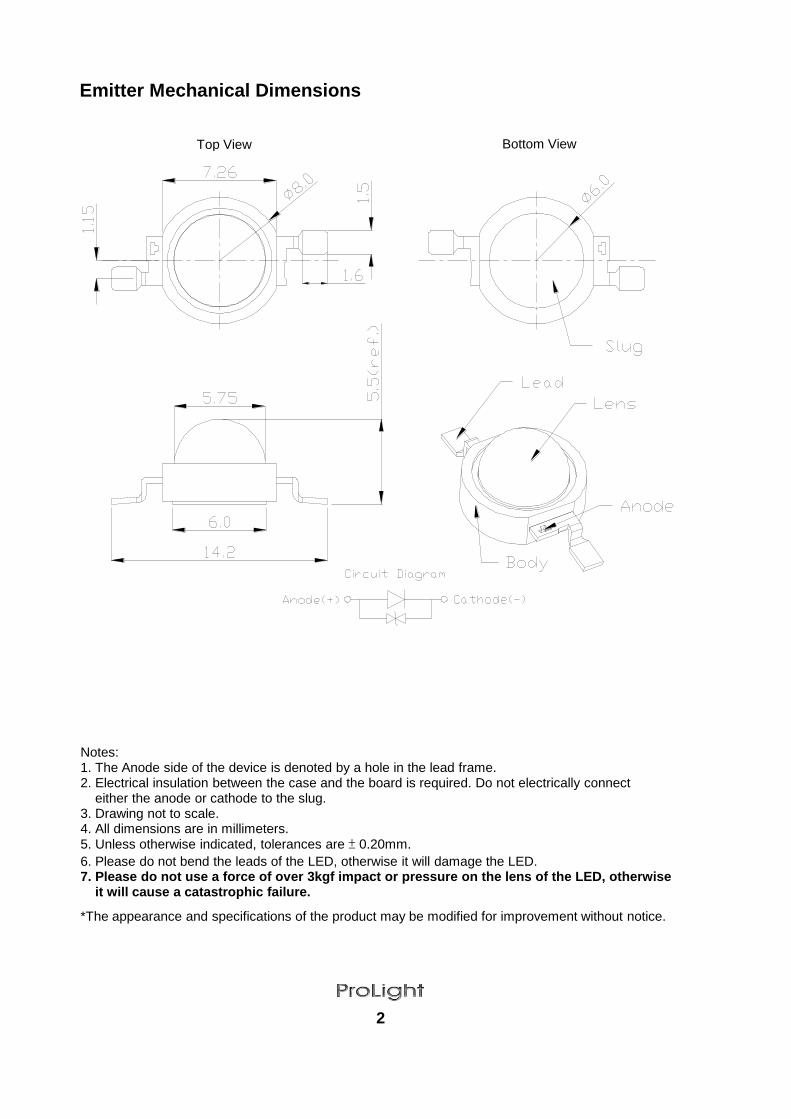
Emitter Mechanical Dimensions
2
Notes: 1. The Anode side of the device is denoted by a hole in the lead frame. 2. Electrical insulation between the case and the board is required. Do not electrically connect either the anode or cathode to the slug. 3. Drawing not to scale. 4. All dimensions are in millimeters. 5. Unless otherwise indicated, tolerances are ± 0.20mm.
6. Please do not bend the leads of the LED, otherwise it will damage the LED. 7. Please do not use a force of over 3kgf impact or pressure on the lens of the LED, otherwise it will cause a catastrophic failure.
*The appearance and specifications of the product may be modified for improvement without notice.
Top View Bottom View

Star Mechanical Dimensions
3
Notes: 1. Slots in aluminum-core PCB for M3 or #4 mounting screw. 2. Electrical interconnection pads labeled on the aluminum-core PCB with "+" and "-" to denote positive and negative, respectively. All positive pads are interconnected, as are all negative pads, allowing for flexibility in array interconnection. 3. Drawing not to scale. 4. All dimensions are in millimeters. 5. Unless otherwise indicated, tolerances are ± 0.20mm.
6. Please do not use a force of over 3kgf impact or pressure on the lens of the LED, otherwise it will cause a catastrophic failure.
*The appearance and specifications of the product may be modified for improvement without notice.
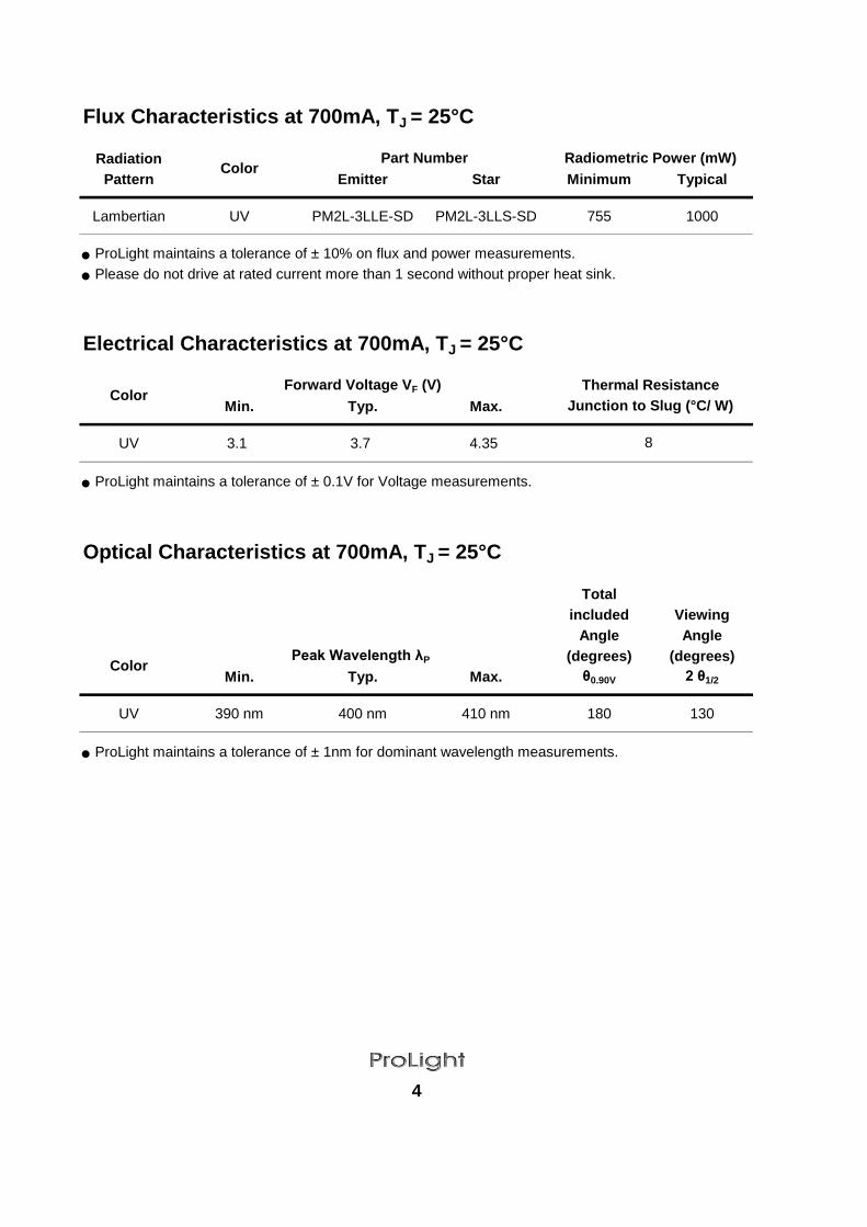
Flux Characteristics at 700mA, TJ = 25°C
Radiation
Pattern Emitter Star Minimum Typical
Lambertian UV PM2L-3LLE-SD PM2L-3LLS-SD 755 1000
● ProLight maintains a tolerance of ± 10% on flux and power measurements.
● Please do not drive at rated current more than 1 second without proper heat sink.
Electrical Characteristics at 700mA, TJ = 25°C
Min. Typ. Max.
UV 3.1 3.7 4.35
● ProLight maintains a tolerance of ± 0.1V for Voltage measurements.
Optical Characteristics at 700mA, TJ = 25°C
Total
included Viewing
Angle Angle
(degrees) (degrees)
Min. Typ. Max. θ0.90V 2 θ1/2
UV 390 nm 400 nm 410 nm 180 130
● ProLight maintains a tolerance of ± 1nm for dominant wavelength measurements.
Forward Voltage VF (V) Thermal Resistance
Junction to Slug (°C/ W)
8
ColorPart Number
4
Radiometric Power (mW)
Peak Wavelength λP,Color
Color

Absolute Maximum Ratings
Parameter
DC Forward Current (mA)
Peak Pulsed Forward Current (mA)
Average Forward Current (mA)
ESD Sensitivity
(HBM per MIL-STD-883E Method 3015.7)
LED Junction Temperature
Operating Board Temperature
at Maximum DC Forward Current
Storage Temperature
Soldering Temperature
Allowable Reflow Cycles
Reverse Voltage
Radiometric Power Bin Structure
T
U
V
● ProLight maintains a tolerance of ± 10% on flux and power measurements.
● The flux bin of the product may be modified for improvement without notice.
● 【1】
The rest of color bins are not 100% ready for order currently. Please ask for quote and order possibility.
Peak Wavelength Bin Structure
1
2
3
4
● ProLight maintains a tolerance of ± 1nm for peak wavelength measurements.
Forward Voltage Bin Structure
Color Bin Code
B
D
E
F
G
● ProLight maintains a tolerance of ± 0.1V for Voltage measurements.
Note: Although several bins are outlined, product availability in a particular bin varies by production run
and by product performance. Not all bins are available in all colors.
5
875 1050 2,3,4 【1】
-40°C - 100°C
JEDEC 020c 260°C
3
Not designed to be driven in reverse bias
-40°C - 120°C
755
Wavelength (nm)
405
Bin CodeMinimum Maximum Available
2,3,4 【1】
【1】1050
Radiometric Power (mW)
> ±500V
Color Bin CodeMinimum Peak Maximum Peak
395 400
400 405
875
1225
Wavelength (nm)
410
UV
700
1000 (less than 1/10 duty cycle@1KHz)
700
120°C
Radiometric Power (mW) Color BinsColor
3.60 3.85
3.85
UV
390 395
UV
Minimum Voltage (V) Maximum Voltage (V)
UV
3.10 3.35
3.35 3.60
4.35
4.10
4.10

Color Spectrum, TJ = 25°C
1. UV
Light Output Characteristics
Relative Light Output vs. Junction Temperature at 700mA
6
Figure 1 Relative Intensity vs. Wavelength Figure 1b. White Color Spectrum of Typical 5500K Part. Figure 1c. Warm White Color Spectrum of Typical 3300K
0.0
0.2
0.4
0.6
0.8
1.0
350 400 450 500 550 600 650 700 750 800
Rela
tive S
pectr
al P
ow
er
Dis
trib
ution
Wavelength (nm)
0
20
40
60
80
100
120
140
160
1 2 3 4 5 6 7 8
Rela
tive L
ight
Outp
ut
(%)
Junction Temperature, TJ (℃)
-20 0 20 40 60 80 100 120
UV
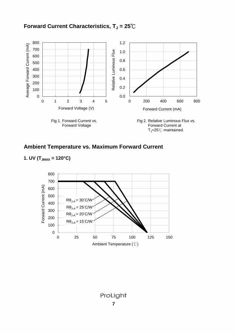
Forward Current Characteristics, TJ = 25℃
Ambient Temperature vs. Maximum Forward Current
1. UV (TJMAX = 120°C)
7
RθJ-A = 60°C/W RθJ-A = 50°C/W RθJ-A = 30°C/W RθJ-A = 40°C/W RθJ-A = 60°C/W RθJ-A = 50°C/W RθJ-A = 30°C/W RθJ-A = 40°C/W
0
100
200
300
400
500
600
700
800
0 1 2 3 4 5
Avera
ge F
orw
ard
Curr
ent
(mA
)
Forward Voltage (V)
Fig 1. Forward Current vs. Forward Voltage
Fig 2. Relative Luminous Flux vs. Forward Current at TJ=25℃ maintained.
0
100
200
300
400
500
600
700
800
0 25 50 75 100 125 150
Forw
ard
Curr
ent
(mA
)
Ambient Temperature (℃)
RθJ-A = 30°C/W
RθJ-A = 25°C/W
RθJ-A = 15°C/W
RθJ-A = 20°C/W
0.0
0.2
0.4
0.6
0.8
1.0
1.2
0 200 400 600 800
Rela
tive L
um
inous F
lux
Forward Current (mA)

Typical Representative Spatial Radiation Pattern
Lambertian Radiation Pattern
8
0
0.1
0.2
0.3
0.4
0.5
0.6
0.7
0.8
0.9
1
-90 -80 -70 -60 -50 -40 -30 -20 -10 0 10 20 30 40 50 60 70 80 90
Rela
tive I
nte
nsity
Angular Displacement (Degrees)

Qualification Reliability Testing
Stress Test Stress Duration Failure Criteria
Room Temperature
Operating Life (RTOL)
Wet High Temperature
Operating Life (WHTOL)
Wet High Temperature
Storage Life (WHTSL)
High Temperature
Storage Life (HTSL)
Low Temperature
Storage Life (LTSL)
Non-operating
Temperature Cycle (TMCL)
Non-operating
Thermal Shock (TMSK)
Variable Vibration
Frequency
Solder Heat Resistance
(SHR)
Solder coverage
on lead
Notes:
1. Depending on the maximum derating curve.
2. Criteria for judging failure
Min.
IF = max DC -
* The test is performed after the LED is cooled down to the room temperature.
3. A failure is an LED that is open or shorted.
9
Test Condition
Solderability
-Initial Level x 0.7
ItemMax.
Initial Level x 1.1
at 260°C for 5 sec.
IF = max DC
Criteria for Judgement
Forward Voltage (VF)
10-2000-10 Hz, log or linear sweep rate,
20 G about 1 min., 1.5 mm, 3X/axis
260°C ± 5°C, 10 sec.
Steam age for 16 hrs., then solder dip
Luminous Flux or
Radiometric Power (ΦV)
Stress Conditions
25°C, IF = max DC (Note 1)
85°C/60%RH, IF = max DC (Note 1)
110°C, non-operating
85°C/85%RH, non-operating
-40°C, non-operating
-40°C to 120°C, 30 min. dwell,
<5 min. transfer
-40°C to 120°C, 20 min. dwell,
Natural Drop
<20 sec. transfer
1500 G, 0.5 msec. pulse,
5 shocks each 6 axis
On concrete from 1.2 m, 3X
Mechanical Shock
1000 hours
1000 hours
Note 2
Note 2
Note 3
Note 3
Note 2
Note 2
1000 hours Note 2
Note 3
Note 3
Note 2
Note 2
1000 hours
1000 hours
200 cycles
200 cycles
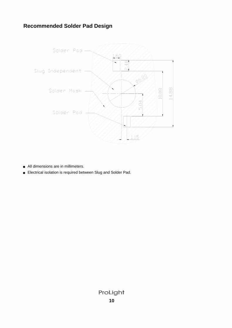
Recommended Solder Pad Design
● All dimensions are in millimeters.
● Electrical isolation is required between Slug and Solder Pad.
10

Reflow Soldering Condition
● We recommend using the M705-S101-S4 solder paste from SMIC (Senju Metal Industry Co., Ltd.)
for lead-free soldering.
● All temperatures refer to topside of the package, measured on the package body surface.
● Repairing should not be done after the LEDs have been soldered. When repairing is unavoidable, a
double-head soldering iron should be used. It should be confirmed beforehand whether the
characteristics of the LEDs will or will not be damaged by repairing.
● Reflow soldering should not be done more than three times.
● When soldering, do not put stress on the LEDs during heating.
● After soldering, do not warp the circuit board.
Time 25°C to Peak Temperature 6 minutes max. 8 minutes max.
11
Time Within 5°C of Actual Peak10-30 seconds 20-40 seconds
Temperature (tP)
Ramp-Down Rate 6°C/second max. 6°C/second max.
– Time (tL) 60-150 seconds 60-150 seconds
Peak/Classification Temperature (TP) 240°C 260°C
– Time (tSmin to tSmax) 60-120 seconds 60-180 seconds
Time maintained above:
– Temperature (TL) 183°C 217°C
Preheat
– Temperature Min (TSmin) 100°C 150°C
– Temperature Max (TSmax) 150°C 200°C
Profile Feature Sn-Pb Eutectic Assembly Pb-Free Assembly
Average Ramp-Up Rate3°C / second max. 3°C / second max.
(TSmax to TP)
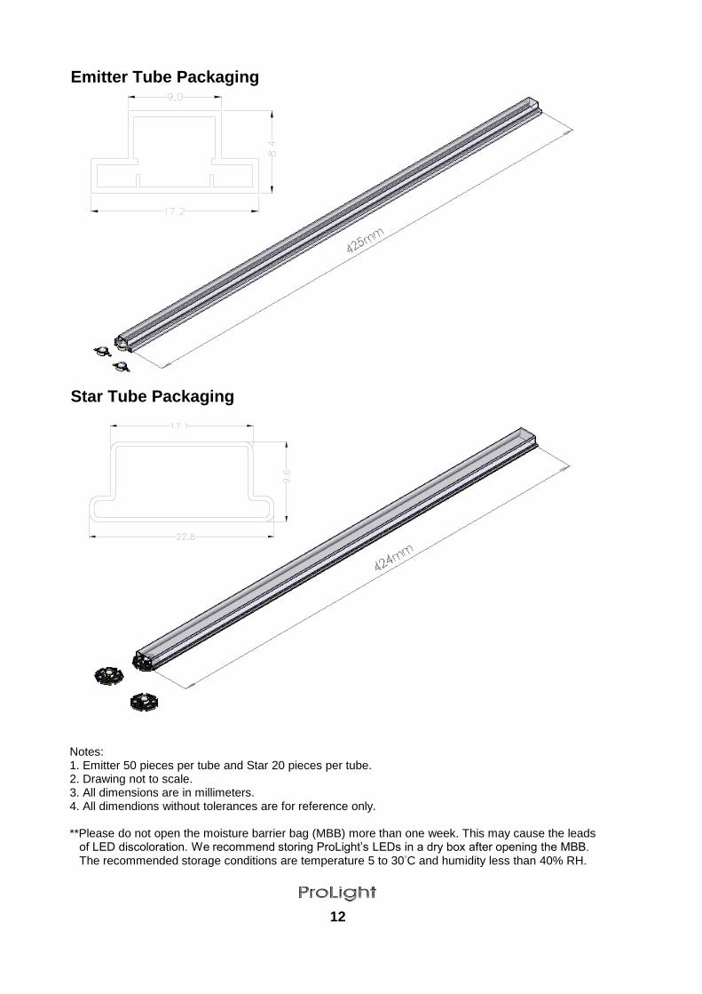
Emitter Tube Packaging
Star Tube Packaging
12
Notes: 1. Emitter 50 pieces per tube and Star 20 pieces per tube. 2. Drawing not to scale. 3. All dimensions are in millimeters. 4. All dimendions without tolerances are for reference only. **Please do not open the moisture barrier bag (MBB) more than one week. This may cause the leads of LED discoloration. We recommend storing ProLight’s LEDs in a dry box after opening the MBB. The recommended storage conditions are temperature 5 to 30°C and humidity less than 40% RH.

Precaution for Use
Handling of Silicone Lens LEDs
13
Notes for handling of silicone lens LEDs ● Please do not use a force of over 3kgf impact or pressure on the silicone lens, otherwise it will cause a catastrophic failure. ● The LEDs should only be picked up by making contact with the sides of the LED body. ● Avoid touching the silicone lens especially by sharp tools such as Tweezers. ● Avoid leaving fingerprints on the silicone lens. ● Please store the LEDs away from dusty areas or seal the product against dust. ● When populating boards in SMT production, there are basically no restrictions regarding the form of the pick and place nozzle, except that mechanical pressure on the silicone lens must be prevented. ● Please do not mold over the silicone lens with another resin. (epoxy, urethane, etc)
╳ ○
● Storage Please do not open the moisture barrier bag (MBB) more than one week. This may cause the leads of LED discoloration. We recommend storing ProLight’s LEDs in a dry box after opening the MBB. The recommended storage conditions are temperature 5 to 30°C and humidity less
than 40% RH. It is also recommended to return the LEDs to the MBB and to reseal the MBB. ● The slug is is not electrically neutral. Therefore, we recommend to isolate the heat sink. ● The LEDs are sensitive to electrostatic discharge. Appropriate ESD protection measures must be taken when working with the LEDs. Non-compliance with ESD protection measures may lead to damage or destruction of the LEDs. ● We recommend using the M705-S101-S4 solder paste from SMIC (Senju Metal Industry Co., Ltd.) for lead-free soldering. ● Any mechanical force or any excess vibration shall not be accepted to apply during cooling process to normal temperature after soldering. ● Please avoid rapid cooling after soldering. ● Components should not be mounted on warped direction of PCB. ● Repairing should not be done after the LEDs have been soldered. When repairing is unavoidable, a heat plate should be used. It should be confirmed beforehand whether the characteristics of the LEDs will or will not be damaged by repairing. ● This device should not be used in any type of fluid such as water, oil, organic solvent and etc. When cleaning is required, isopropyl alcohol should be used. ● When the LEDs are illuminating, operating current should be decide after considering the package maximum temperature. ● The appearance, specifications and flux bin of the product may be modified for improvement without notice. Please refer to the below website for the latest datasheets. http://www.prolightopto.com/