Embed Size (px)
Citation preview

FEATURES
PTC-15
� Equivalent Noise Resistance:
� Operating temperature**: �40°C + 90°C (�40°F + 194°F)
� Mechanical rotation angle: 265° ± 5°
ELECTRICAL SPECIFICATIONSMECHANICAL SPECIFICATIONS
PTC15
Series
(See note 1)
(See note 4)
2020
Tolerance
0505 = ± 5%
0707 = ± 7%
1010 = ± 10%
2020 = ± 20%
3030 = ± 30%
Value
504 = 500 K
(See note 3)
505 = 5 M
223 = 22 K
000 = C M
Torque
� = Standard
L= Low Torque
(See note 7)
Detents
Rotors
CFGLMNRTXWYZ
H01L A
Taper
A = Lin.
B = Log.
C = Alog.
Magazine
T
(See note 6)
RO= RedNE= BlackVE= GreenAM= YellowAZ= BlueMA= BrownGR= GreyNA= Orange
Shaft/rotor colour
Long Life
E= Long life
(See note 5)
Shaft Thum.
01 � Fig. 1
28 � Fig. 28
Wiper position
PM = 50%
PF = Final
(See note 2)
H01 H2.5H05 H5H15 HA5H06 BH02 H2.5PH10 H5PV02 V12.5V12 VAV15 V15V17 V17.5V18 DV21 V12.5PV22 VAPV23 V15P
MountingMethod
Code
NOTES (1) "Z" adjustment only available on "H" versions. Standard colour for the �T� rotor: Orange
(2) Terminals styles: "P" are crimped terminals. V=Vertical adjust; H=Horizontal Adjust
000 = CM: SPDT switch 45°
Example: +7% -5%
07 05negative tolerance
(4) Non standard tolerance, check availability.
Example: 10 1Numb of zeros
(3) Value
(7)
NOTE: The information contained here should be used for reference purposes only.
If you wish to use your own custom plastic shaft/knob/actuator please contact Piher for advice about compatible materials.(9)
* Others check availability.
� Life*: Up to 10K cycles
PAIPAMPAFP1IP1FP02
P38
(See note 9)
- -
** Up to +120ºC depending on application. Check availability.
56
� Range of values*
� Max. Voltage: 250 VDC (lin) 125 VDC (no lin)
� Nominal Power 70°C (158°F) (see power rating curve)
0.50 W (lin) 0.25 W (no lin)
� Tolerance*: ± 20%± 30%
� Taper* (Log. & Alog. only Rn 1K) Lin ; Log; Alog.
www.piher.net
(See note 8)
First two digits of the value.
Code:
positive tolerance
Code:
(5) Life Standard: 1K cyclesLong life: 10K cycles
(6) Colour shaft/ rotor: Potentiometer without shaft: only rotorPotentiometer with shaft: only shaft
15 mm CermetPotentiometer
� Stop torque: > 10 Ncm. ( >14 in-oz)
� Torque: 0.5 to 2.5 Ncm.(0.7 to 3.4 in-oz)
� Electrical rotation angle: 240° ± 20°
(8) Magazines (35 pcs/mag): available for VA (12.5), V (12.5), V (12.5P), V (15), V15 (P) and H models.For more information please contact your nearest Piher supplier.
� Residual resistance*:
HOW TO ORDER
OPTIONAL EXTRAS
223
- Cermet resistive element.
- Plastic material according to UL94V-0.
- Alumina substrate.
- IP54 protection according to IEC 60529.
- Also upon request:
� Wiper positioned at initial, 50% or fully clockwise.
� Long life model for low cost control pot. applications.
� Supplied in magazines for automatic insertion.
� Low torque option.
� Available as SPDT switch.
� Laser trimming for tighter tolerances.
� Mechanical detents.
� Special tapers.

www.piher.net
(Max. 16 digits)
This way of ordering should be used for options which are not includedin the "How to order" standard and optional extras.
PTC-15 LH 01 + DRAWING NUMBER
STANDARD OPTIONSHOW TO ORDER CUSTOM DRAWING
1000 cyclesLife
Wiper position Initial
StandardTorque
Shaft colour Natural
Rotor colour Natural
Detents None
57
Wipers positioned at initial (without shaft) Wipers positioned at 50% (without shaft)
ROTORS
3.35 ±0.05
3.3
5±0
.05 ±0.05
3.0
5±0
.05
1.2Ø4.05±0.05
Rotor C Rotor F Rotor R Rotor T
54°
Ø4.4±0.05
23°
L = Screw driver
thru hole
Wiperposition
3.05
4.05
42.5°
Wiperposition
N =Removable shaftor thumbwheel
G =Removable shaftor thumbwheel
M =Hexagonal thru hole
4
Y =Adjustable from terminal side
Z =Adjustable from collector side
1.4
+0.5 +0.5
A S E
A = Initial S = Wiper E = Final
A = Initial S = Wiper E = Final
A
S
E
D 13.5
1.3
v (12.5)
4
12.5
12.5
1.3
5
X = Adjustable from collector side
L
W = Adjustable from terminal side
L
7.5 +0.3 7.5 +0.36
0.8
With shaft With thumbwheel
3.5
2
Ø4.02
±0
.05
-0.11-0
.1 3.8
±0.05
± 0.05
± 0.05
4.05 ±0.05
3.05
42.5°
2.5
5
B
4.4+0.1
4.4+0.1
6
4
+0.2 15+0.2
41+0.1
9.6
+0
.2
17.1
+0
.2
8.8
1.3+0.1
4
5+0.1 5+0.1
15+0.2
4
1+0.1
12
+0
.2
19.5
+0
.2
10
1.3+0.1
5
h a 5
5+0.1 5
+0.1
6
5
+0.2 15+0.2
4
1+0.1
10
+0
.2
17.5
+0
.2
10
1.3+0.1
5
h (5)
15+0.2
4
1+0.1
6
7.5
+0.2
+0.24
18.5
+0.1
8.8
11
1.3
3.2
7
6
7
+0.2
±0.2
15+0.2
4
1+0.1
7.5
7
+0.1
10
8.8+0.2
11
+0.1
VERTICAL MOUNTING � HORIZONTAL ADJUSTMENT
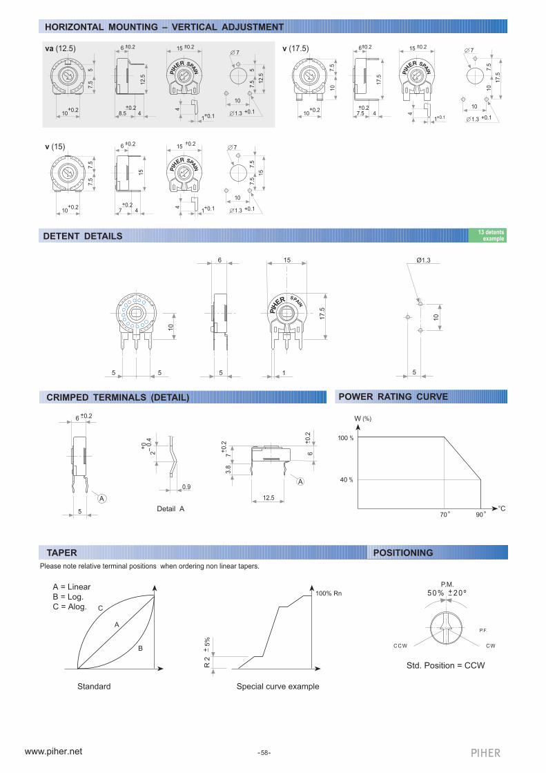
HORIZONTAL MOUNTING � VERTICAL ADJUSTMENT
5+0.1 5
+0.1
6
2.5
+0.2 15+0.2
4
1+0.1
10
+0
.2
17.5
+0
.2
10
1.3+0.1
2.5
h (2.5)
10+0.2
7.5
5
13.5
6
5
±0.2
HORIZONTAL MOUNTING � VERTICAL ADJUSTMENT
v (17.5)
4
17.5
17.5
1.3
7.5
±0.2
www.piher.net
6
7.5
15 ±0.2
4
1+0.1
±0.2±0.26
8.5
15+0.2
4
1+0.1
6
7
+0.2
va (12.5)
10+0.2
7.5
5
+0.24
12.5
15
4
1+0.1
7.5
7
+0.1
10
12.5
1.3
5
+0.2
10
7
+0.1
1010
+0.2
10
7.5
+0.2
7.5
7
+0.1
10
10+0.2
58
v (15)
4
15
15
1.3
7.5
7.5
7.5
5
10
Ø1.3
10
5 5
6
5
15
17.5
1
PIH
ERSPA
IN
DETENT DETAILS13 detents
example
3.8
A
6
12.5
+0.2
7+
0.2
A
6
5
+0.2
Detail A
2� 0
.4+
0
0.9
W
100 %
(%)
40 %
70 90C
POWER RATING CURVECRIMPED TERMINALS (DETAIL)
Please note relative terminal positions when ordering non linear tapers.
A
B
R 2
+ 5
%
A = Linear
B = Log.
C = Alog.
Standard Special curve example
100% Rn
C
TAPER
Std. Position = CCW
C C W C W
5 0 % + 2 0 º
P.F.
P.M.
POSITIONING
www.piher.net
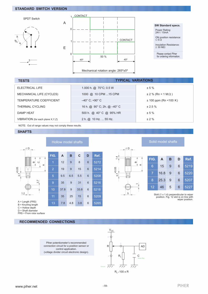
TESTS TYPICAL VARIATIONS
SHAFTS
Solid model shafts
A = Length (FRS)
B = Knurling length
C = Hollow depth
D = Shaft diameterFRS = From rotor surface
C
8
31
15
5.5
33.8
15
3.8
FIG.
12
A B D
1
2
5
9
19
9.5
35
9
9
9
6.5
6
6
6
6
10 37.8 9 6
11 35 25 6
13 7.8 4.8 6
Ref.
5272
5214
5208
5216
5218
5209
5265
Slott (1 x 1.4) perpendicular to wiperposition. Fig. 12 slot is on line with
wiper position.
ELECTRICAL LIFE
MECHANICAL LIFE (CYCLES)
TEMPERATURE COEFFICIENT
THERMAL CYCLING
DAMP HEAT
VIBRATION (for each plane X,Y,Z)
NOTE: Out of range values may not comply these results.
SHAFTS
DD
59
Hollow model shafts
B
5
1
3.7
+0.0
5
A
1.4
B
1.2
3.7
3.7
+0.0
5
A
C
± 5 %
± 2 % (Rn < 1 M )
± 100 ppm (Rn <100 K)
± 2.5 %
± 5 %
± 2 %
1.000 h. @ 70°C; 0.5 W
1000 @ 10 CPM ...15 CPM
�40° C; +90° C
16 h. @ 90° C; 2h. @ �40° C
500 h. @ 40° C @ 95% HR
2 h. @ 10 Hz. ... 55 Hz.
FIG.
6
7
8
12
A
15
16.8
25.3
46
B
9
9
9
5
D
6
6
6
6
Ref.
5219
5220
5207
5227
STANDARD SWITCH VERSION
SPDT Switch
45 0
1
1
0
0
A
E
50 %
Mechanical rotation angle: 265º±5º
CONTACT
CONTACT
45º45º
SW Standard specs.
Please contact Piherfor ordering information.
Power Rating:24V / 15mA
ON position resistance: 5
Insulation Resistance: 30 M
RECOMMENDED CONNECTIONS
Piher potentiometer�s recommended
connection circuit for a position sensor or
control application.
(voltage divider circuit electronic design).
R AD
RL
RL 100 x R
VCC
CNoise filter.
Ground.
E
A
S

www.piher.net
SHAFTSSHAFTS
Fig. 20 / Ref. 5369* Fig. 21 / Ref. 6031* Fig. 22 / Ref. 6029 Fig. 23 / Ref. 6022 Fig. 29 / Ref.6162 Fig. 25 / Ref. 6059
40
o
Ø 6 Ø 6
42o
4.6
4.6
By default shafts, knobs & & thumweels are delivered unassembled.
Mounted shafts, knobs & thumbweels are delivered at random position. Positioning available check availability..
If you wish to use your own plastic shaft/knob/actuator please contact Piher for advice about compatible materials.
* Not available in self extinguishable plastic
By default shafts, knobs & & thumweels are delivered unassembled.
Mounted shafts, knobs & thumbweels are delivered at random position. Positioning available check availability..
If you wish to use your own plastic shaft/knob/actuator please contact Piher for advice about compatible materials.
SHAFTS
12
Ø6
Ø4
28
Ø6
37,8
Ø6
15
60
13.8
36
o
4,6
THUMBWHEEL
1.316
Fig. 4 / Ref. 5371
Fig. 27 / Ref. 5268* Fig. 28 / Ref. 6055
9.5
Ø6
41.5
Fig. 15 / Ref. 5217
12
Ø4
8
3
5º
Fig. 17 / Ref. 5210
23.1
Ø5.9
Fig. 18 / Ref. 5271
11.3
Ø4
Fig. 19 / Ref. 6032*
28.7
Ø6
10.7
4,1
Fig. 3 / Ref. 5372
12
Ø4
23.4
261
0
www.piher.net
P13P09 P10 P11 P12
P08P07P06P05P04
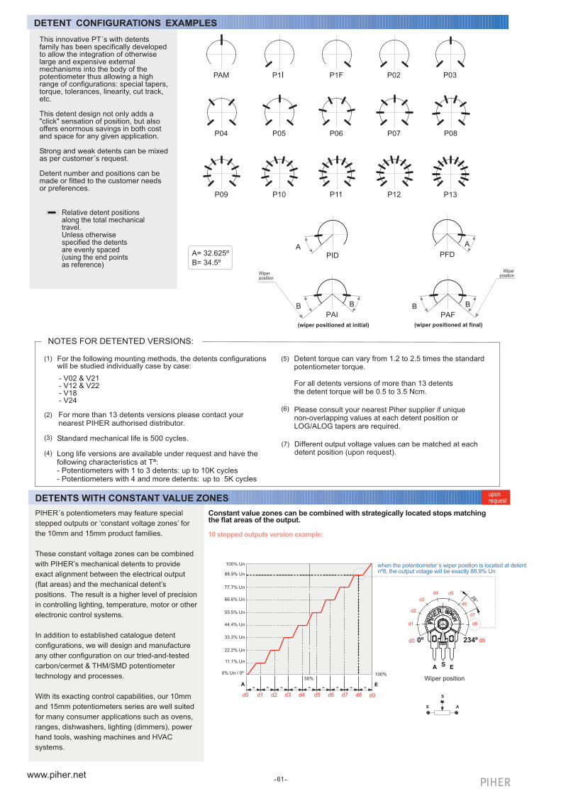
Long life versions are available under request and have thefollowing characteristics at Tª: - Potentiometers with 1 to 3 detents: up to 10K cycles- Potentiometers with 4 and more detents: up to 5K cycles
Different output voltage values can be matched at eachdetent position (upon request).
For the following mounting methods, the detents configurationswill be studied individually case by case:
- V02 & V21- V12 & V22- V18- V24
NOTES FOR DETENTED VERSIONS:
Standard mechanical life is 500 cycles.
Detent torque can vary from 1.2 to 2.5 times the standardpotentiometer torque.
For all detents versions of more than 13 detentsthe detent torque will be 0.5 to 3.5 Ncm.
Please consult your nearest Piher supplier if uniquenon-overlapping values at each detent position orLOG/ALOG tapers are required.
For more than 13 detents versions please contact yournearest PIHER authorised distributor.
d1 d2 d3 d4 d5 d6 d7 d8
Wiper position
d1
d2
d3
d4 d5
d6
d7
d8
d0 d9
d0 d9
61
E A
S
EA== = = = = ===
°62
EA
(1)
(3)
(5)
(2)(6)
(7)
(4)
DETENT CONFIGURATIONS EXAMPLES
DETENTS WITH CONSTANT VALUE ZONESuponrequest
Constant value zones can be combined with strategically located stops matchingthe flat areas of the output.
when the potentiometer´s wiper position is located at detentnº8, the output votage will be exactly 88.9% Un
10 stepped outputs version example:
P02P1FP1I P03PAM
PAIB B
PAFB B
Wiperposition
Wiperposition
A= 32.625º
B= 34.5ºPID
APFD
A
(wiper positioned at initial) (wiper positioned at final)
Relative detent positionsalong the total mechanicaltravel.Unless otherwisespecified the detentsare evenly spaced(using the end pointsas reference)
This innovative PT´s with detentsfamily has been specifically developedto allow the integration of otherwiselarge and expensive externalmechanisms into the body of thepotentiometer thus allowing a highrange of configurations: special tapers,torque, tolerances, linearity, cut track,etc.
This detent design not only adds a"click" sensation of position, but alsooffers enormous savings in both costand space for any given application.
Strong and weak detents can be mixedas per customer´s request.
Detent number and positions can bemade or fitted to the customer needsor preferences.
PIHER´s potentiometers may feature special
stepped outputs or �constant voltage zones� for
the 10mm and 15mm product families.
These constant voltage zones can be combined
with PIHER�s mechanical detents to provide
exact alignment between the electrical output
(flat areas) and the mechanical detent�s
positions. The result is a higher level of precision
in controlling lighting, temperature, motor or other
electronic control systems.
In addition to established catalogue detent
configurations, we will design and manufacture
any other configuration on our tried-and-tested
carbon/cermet & THM/SMD potentiometer
technology and processes.
With its exacting control capabilities, our 10mm
and 15mm potentiometers series are well suited
for many consumer applications such as ovens,
ranges, dishwashers, lighting (dimmers), power
hand tools, washing machines and HVAC
systems.
100%
88.9% Un
77.7% Un
66.6% Un
55.5% Un
44.4% Un
33.3% Un
22.2% Un
11.1% Un
0% Un / 0º
100% Un
50%
0º 234º
S

www.piher.net
Piher Sensors & Controls SA
Polígono Industrial MunicipalVial T2 Nº2231500 Tudela - SpainTel: +34-948-820450
www.piher.net
Contact
Improved repeatability
DETENTS WITH CONSTANT VALUE ZONESapplicationnotes
Unique, non-overlapping values at each stop (detent position)
Prevents output value change due to light vibration or accidental rotor micro-movements
Fully customisable according to customer´s needs
Cost effective replacement for absolute encoders
Main advantages
Absolute encoders can easily be
replaced connecting the potentiometer to
the microprocessor´s
analogue input.
Design tip. Cost-effectiveness
All Piher products can be adapted to meet customer´s requirements.Due to continuous process improvement, specifications are subject to change without notice.Please always use the datasheets published at our website www.piher.net for the most up-to-date information.
Disclaimer
v190218
Pb
A
ccord
ing
toE
LV(2
000/53/EC) / RoH
S3
(201
5/8
63/E
U
)
The product information in this catalogue is for reference purposes. Please consult for the most up to date and accurate designinformation.
Piher Sensors & Controls S.A., its affiliates, agents, and employees, and all persons acting on its or their behalf (collectively, �Piher�),disclaim any and all liability for any errors, inaccuracies or incompleteness contained herein or in any other disclosure relating to anyproduct described herein.
Piher disclaims any and all liability arising out of the use or application of any product described herein or of any information providedherein to the maximum extent permitted by law. The product specifications do not expand or otherwise modify Piher�s terms andconditions of sale, including but not limited to the warranty expressed therein, which apply to these products.
No licence, express or implied, by estoppel or otherwise, to any intellectual property rights is granted by this document or by anyconduct of Piher.
The products shown herein are not designed for use in medical, life-saving, or life-sustaining applications unless otherwise expresslyindicated. Customers using or selling Piher products not expressly indicated for use in such applications do so entirely at their ownrisk and agree to fully indemnify Piher for any damages arising or resulting from such use or sale. Please contact authorised Piherpersonnel to obtain written terms and condit ions regarding products designed for such appl icat ions.
Product names and markings noted herein may be trademarks of their respective owners.
Information contained in and/or attached to this catalogue may be subject to export control regulations of the European Community,USA, or other countries. Each recipient of this document is responsible to ensure that usage and/or transfer of any informationcontained in this document complies with all relevant export control regulations. If you are in any doubt about the export controlrestrictions that apply to this information, please contact the sender immediately. For any Piher Exports, Note: All products / technologiesare EAR99 Classified commodities. Exports from the United States are in accordance with the Export Administration Regulations.Diversion contrary to US law is prohibited.
Piher is an AmphenolTM company.
By combining the constant value zones with the detents, engineers can align the samevoltage values with each of the detent stops when rotating the control both forward andbackward.
This provides clear mechanical positions that are not only repeatable, but perfectly alignedelectrical outputs at each of the (detent) angles.
Piher´s detents also prevent output values from changing due to vibration or accidentalrotor movements, furthering reliable control consistency.