Embed Size (px)
Citation preview
Requirements Engineeringdoi: 10.1007/s00766-013-0169-4
Features meet Scenarios: Modeling and Consistency-CheckingScenario-Based Product Line Specifications
Joel Greenyer · Amir Molzam Sharifloo · Maxime Cordy∗ · Patrick
Heymans
Received: 22nd November 2012 / Accepted: 26 March 2013
Abstract Modern software-intensive systems typically
consist of multiple components that provide many func-
tions by their interaction. Moreover, often not only a
single product, but a whole product line with different
compositions of components and functions must be de-
veloped. To cope with this complexity, engineers need
intuitive, but precise means for specifying the require-
ments for these systems and require tools for automat-
ically finding inconsistencies within the requirements,
because inconsistencies could lead to costly iterations
in the later development. In recent work, we proposed
a technique for the scenario-based specification of inter-
actions in product lines by a combination of Modal Se-
quence Diagrams and Feature Diagrams. Furthermore,
we elaborated an efficient consistency-checking tech-
nique based on a dedicated model-checking approachfor product lines. In this paper, we report on further
evaluations that underline significant performance ben-
efits of our approach. We describe further optimizations
and detail on how we encode the consistency-checking
problem for a model-checker.
Many modern software-intensive systems consist of
multiple components interacting together to deliver the
intended functionality. Often, these systems come in
many variants (products) and are managed together as
a software product line. This variability is the source of
* FNRS research fellow
Joel Greenyer · Amir Molzam ShariflooDependable Evolvable Pervasive Software Engineering,Dipartimento di Elettronica e Informazione,Politecnico di Milano, ItalyE-mail: {greenyer|molzam}@elet.polimi.it
Maxime Cordy · Patrick HeymanPReCISE Research Center,University of Namur, BelgiumE-mail: {mcr|phe}@info.fundp.ac.be
additional complexity which can cause inconsistencies
and offset the economies of scale promised by product-
line engineering. Engineers thus need intuitive, yet pre-
cise means for specifying requirements and require tools
for automatically detecting inconsistencies within these
requirements. In recent work, we proposed a technique
for the scenario-based specification of interactions in
product lines by a combination of Modal Sequence Di-
agrams and Feature Diagrams. Furthermore, we elabo-
rated an efficient consistency-checking technique based
on a dedicated model-checking approach especially tai-
lored for product lines. In this paper, we report on fur-
ther evaluations that underline significant performance
benefits of our approach. We describe further optimiza-
tions and detail on how we encode the consistency-
checking problem for a model-checker.
Keywords scenario-based specification; product lines;
feature compositions; consistency
1 Introduction
Modern software-intensive systems in areas like trans-
portation or manufacturing, but also information sys-
tems, typically consist of many components that pro-
vide functions by their interaction. These interactions
are sometimes safety-, security-, or business-critical and
must satisfy complex protocol specifications.
Moreover, often today not only a single software
product, but a whole product line, i.e., many variants of
a product, must be developed. Doing this individually
is often impractical, so the goal of product line engineer-
ing [28] is to consider all the variants together through-
out the whole development process. One widespread ap-
proach to organize a product line is to capture the sets
2 Joel Greenyer et al.
of components and functions that may or may not be
present in different variants into features.
Creating a precise specification of a product line,
however, is a major requirements engineering challenge.
Not only complex interactions and many product vari-
ants must be specified, but the behavioral requirements
usually induce dependencies and conflicts among fea-
tures. Consequently, the requirements have to be care-
fully revised to ensure that the features can be consis-
tently combined. If inconsistencies remain undetected,
desired product variants may not be realizable without
late, and thus costly, iterations.
As an example we consider a simplified specification
of an autonomous rail vehicle, inspired by the RailCab
project at the University of Paderborn1. The RailCab
track system is divided in sections. For every variant of
the system we specify that the vehicles, called RailCabs,
must request a switch controller the permission to enter
a switch. The switch controller must then acknowledge
or deny such a request. Let us now consider different
variants. In one, the switch controller allows only one
RailCab to pass at a time. In another variant, two Rail-
Cabs shall be able to coordinate for a joint entry. There
shall be also a third variant where both functions are
present. However, suppose that the requirements for the
joint entry strictly require the switch control to grant
two RailCabs the permission to enter, but the blocking
feature allows this under no circumstances. In this case,
the product line specification is inconsistent.
We propose a scenario-based approach for the in-
tuitive, but precise specification of the interaction be-
havior of components in product lines. We also present
a novel, efficient approach for checking the consistency
of such product line specifications via model checking.
Our approach is based on specifying product lines by a
combination of Modal Sequence Diagrams (MSDs) and
feature diagrams [24,30].
MSDs are a flexible variant of Live Sequence Charts
(LSCs) [11], proposed by Harel and Maoz [19]. They are
an intuitive, visual language for specifying sequences of
messages that may, must, or must not occur in a sys-
tem. The advantage of this approach is that it allows
the requirements engineers to focus on the requirements
during one particular scenario in the system at a time.
This is a natural way to conceive and communicate re-
quirements. Moreover, the behavioral aspects can be
specified separately for each feature. For a particular
product, the overall specification can then be composed
by simply forming the union of the MSDs correspond-
ing to the selected features. Thus, no elaborate feature
composition mechanisms are required.
1 Neue Bahntechnik Paderborn/RailCab, http://www-nbp.upb.de
In a scenario-based approach, however, contradic-
tions among the different scenarios may be easily in-
troduced. We therefore elaborated a novel technique
for the efficient consistency checking of the specifica-
tions for all the variants in a product line. Inspired by
an earlier approach by Harel et al. [18], we formulate
the consistency checking problem as a model-checking
problem. The novelties that we introduce are to (1) re-
late the MSDs to the features they belong to, (2) con-
sider the constraints that determine the valid feature
combinations as expressed in a feature diagram (see
Section 2.1).
Then, we employ a recently developed dedicated
model-checking technique for product lines [7,8], which
is capable of checking properties for many product vari-
ants at once. This approach is generally much more effi-
cient than the alternative “brute force” approach, called
the enumarative approach, which consists in checking
each individual product’s model separately. This is be-
cause costly multiple verifications of “common” behav-
ior between the products are now avoided. If the specifi-
cation is inconsistent, the model checking will generate
counterexamples, which support the engineer in under-
standing the inconsistencies among the MSDs of dif-
ferent features. Here another benefit of the dedicated
model-checking approach is that it presents concisely
to the engineer the combinations of features that con-
tain a particular contradiction. If the MSD specification
is consistent, our technique can even help the require-
ments engineer in refining the specification so that a
state-based implementation for the components can be
derived for every product. The latter capability, how-
ever, remains an outlook of this paper.
To illustrate the applicability of our approach, we
developed a tool that allows one to model the variabil-
ity and the behavior of a product line in the form of
a feature diagram and a set of MSDs. Then, it trans-
forms these models into a NuSMV model. NuSMV is
an industry-strength symbolic model checker that was
recently extended with efficient algorithms for product
line verification [7]. The key idea of these algorithms is
to introduce one Boolean variable per feature, and to as-
sociate the effect of each feature with the corresponding
variable. Thanks to that information, the algorithms
check only once the bevahiors that are common among
multiple products. This leads to improvements in effi-
ciency.
However, NuSMV is a symbolic model checker, and
its efficiency highly depends on the number of vari-
ables. Therefore, the dedicated algorithms may not al-
ways perform better than an individual verification of
each variant, which does not require the introduction
of additional variables. In our previous work [15], we
Features meet Scenarios: Modeling and Consistency-Checking Scenario-Based Product Line Specifications 3
performed a series of experiments that showed that
the dedicated approach outperforms the enumerative
approach in most cases, but not always. On the ba-
sis of the experiments performed, however, we could
only speculate why in certain cases the enumerative ap-
proach performed better.
In this paper, we extend previous work [15]. The
contribution is the following
1. Extended evaluation (Section 5.3). We perform
further experiments with the object of answering
the open question about when exactly the dedicated
approach performs better than the enumerative one.
For this purpose, we check further technical exam-
ples that we can scale systematically in the number
of features, product, and scenarios. The results al-
low us to revise our previous conclusions and infer
a set of factors that affect the performance.
2. Encoding scenarios and features in NuSMV
(Sections 4.1 and 4.2). We explain the principles of
our transformation from MSDs to the input for the
NuSMV model-checker, as well as how we encode
the dependencies between features into the resulting
NuSMV model. Of particular interest here is how
we used the NuSMV language constructs to encode
the dependencies between MSDs and features in an
efficient way.
3. Optimization of the encoding (Sections 4.2 and
4.3). We explain optimizations in our encoding from
MSDs and feature diagrams to the input for the
NuSMV model-checker that further increase the per-
formance benefits of the dedicated model-checking
approach.
Moreover, we included new foundations that are pre-
requisites for understanding the new contributions, and
are thus necessary for this paper to be self-contained
(Section 2.4). We briefly present NuSMV’s input lan-
guage. We also overview the principles of symbolic model
checking algorithms as they are implemented in NuSMV.
Finally, we added a brief discussion of very recent re-
lated work.
The paper is structured as follows. We introduce the
foundations in Sect. 2 and present our scenario-based
product line specification approach in Sect. 3. We then
explain the consistency checking technique in Sect. 4.
In Sect. 5, we report the evaluation of our approach and
discuss the related work in Sect. 6. Last, we conclude
and provide an outlook in Sect. 7.
2 Foundations
Our approach relies on feature diagrams and MSDs as
well as a behavioral modeling and model-checking tech-
�����������
���� ������ �����������
�����������
���� ������ ������
�����������
������� ������ �������
�����������
����������� ������ �����
���������������
�������
Legend:a a= And = Or = Optional
Fig. 1 The feature diagram for the RailCab example
nique for product lines. This section briefly recalls these
concepts.
2.1 Representing Variability with Feature Diagrams
A popular approach to describe commonality and vari-
ability in product lines is to use feature diagrams [24]. A
feature diagram is essentially a hierarchical decomposi-
tion of features. Nodes in the diagram are features and
edges specify how features are decomposed into child
features. A parent-child relationship can have differ-
ent types, which constrain the valid combinations of
features that can make up a product. The usual de-
composition types are AND, OR, and XOR. An AND
decomposition means that when the parent feature is
present in the product, all its children must be present
as well except those explicitly labelled as optional2. An
OR (resp. XOR) relationship implies that at least (resp.
exactly) one child feature must be present when the par-
ent feature is. There also exist cross-tree relationships
among the features: the presence of one feature may
require or exclude the presence of another feature. Ad-
ditionally, we can define arbitrary Boolean constraints
over the set of features. We stick to the formal seman-
tics extensively defined in [30].
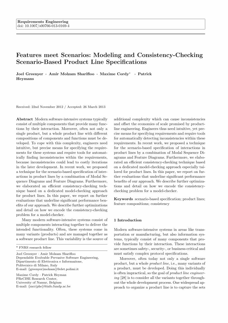
Figure 1 shows the feature diagram of our RailCab
example. The root feature RailCab is always mandatory.
It has two compulsory child features, namely Mergingswitch policy and Merging switch registration. The for-
mer has two additional child features with an OR re-
lationship. Altogether, the diagram thus defines three
product variants.
2.2 Scenario-Based Modeling with MSDs
MSDs were proposed by Harel and Maoz as a formal in-
terpretation of UML sequence diagrams, based on the
concepts of LSCs [19]. In the following, we explain the
2 Optional features are not used in the example appearingin this paper
4 Joel Greenyer et al.
basics of MSDs using our running example, and detail
the interpretation of MSDs that we consider in our ap-
proach.
An MSD specification consists of a set of MSDs. An
MSD can be existential or universal. Existential dia-
grams specify sequences of events that must be possi-
ble to occur in the system. Universal diagrams specify
requirements that must be satisfied by all sequences of
events that occur. In this paper, we focus on universal
MSDs.be extended to support existential MSDs.
Each lifeline in an MSD represents an object in an
object system that consists of environment objects and
system objects. The set of system objects is called the
system; the set of environment objects is called the en-
vironment.
The objects can interchange messages. A message
has a name and a sending and receiving object. In this
paper, we consider only synchronous messages where
the sending and receiving of the message is a single
event. Our approach can, however, be easily extended
to support asynchronous communication. We call the
sending and receiving of a message a message event or
simply event.
The messages in a universal MSD can have a tem-
perature and an execution kind. The temperature can
be either hot or cold ; the execution kind can be either
monitored or executed. The temperature and execution
kind encode safety resp. liveness properties for message
events intuitively as follows. If during the scenario mod-
eled by an MSD we reach a monitored messages, this
means that this event may happen. If instead we reach
an executed message, this event must eventually hap-
pen (liveness). If we reach a cold message, this message
may be violated. A violation is when an event occurs
that is also represented by another message in the same
MSD that is expected to occur at another time in the
scenario, i.e., before or after. Events that are not rep-
resented by a message in the MSD do not lead to vio-
lations (they are ignored). If we reach a hot message,
no violation must occur. Violations of cold messages
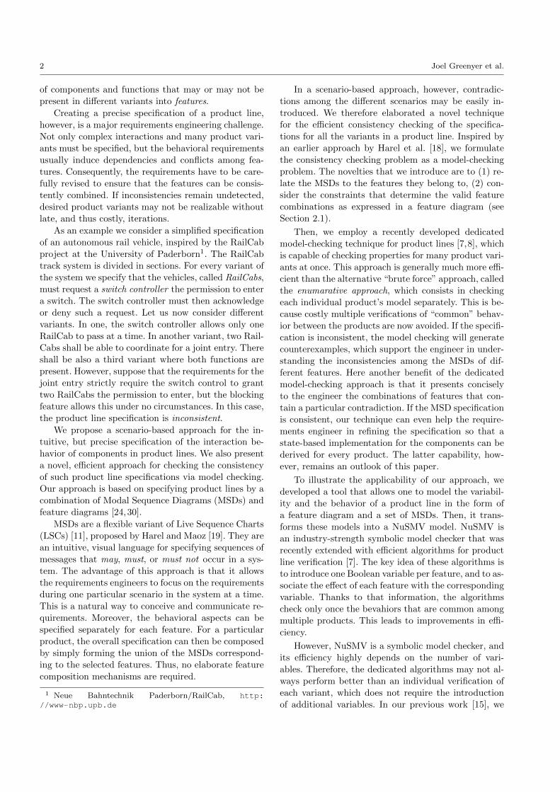
lead to the termination or “reset” of the scenario. Fig-
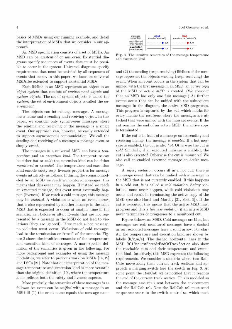
ure 2 shows the intuitive semantics of the temperature
and execution kind of messages. A more specific def-
inition of the semantics is given in the following. For
more background and examples of using the message
modalities, we refer to previous work on MSDs [14, 19]
and LSCs [21]. Note that our interpretation of the mes-
sage temperature and execution kind is more versatile
than the original definition [19], where the temperature
alone reflects both the safety and liveness aspects.
More precisely, the semantics of these messages is as
follows: An event can be unified with a message in an
MSD iff (1) the event name equals the message name
cold(can be “violated”)
hot(must not be “violated”)
monitored(may happen)
executed(must happen)
c,m
c,e
h,m
h,e
message semantics:
Fig. 2 The intuitive semantics of the message temperatureand execution kind
and (2) the sending (resp. receiving) lifelines of the mes-
sage represent the objects sending (resp. receiving) the
event. When an event occurs in the system that can be
unified with the first message in an MSD, an active copy
of the MSD or active MSD is created. (We consider
that an MSD has only one first message.) As further
events occur that can be unified with the subsequent
messages in the diagram, the active MSD progresses.
This progress is captured by the cut, which marks for
every lifeline the locations where the messages are at-
tached that were unified with the message events. If the
cut reaches the end of an active MSD, the active copy
is terminated.
If the cut is in front of a message on its sending and
receiving lifeline, the message is enabled. If a hot mes-
sage is enabled, the cut is also hot. Otherwise the cut is
cold. Similarly, if an executed message is enabled, the
cut is also executed. Otherwise the cut is monitored. We
also call an enabled executed message an active mes-
sage.
A safety violation occurs iff in a hot cut, there is
a message event that can be unified with a message in
the MSD that is not currently enabled. If this happens
in a cold cut, it is called a cold violation. Safety vio-
lations must never happen, while cold violations may
occur and result in terminating the active copy of the
MSD (see also Harel and Marelly [21, Sect. 5]). If the
cut is executed, this means that the active MSD must
progress and it is a liveness violation if an active MSD
never terminates or progresses to a monitored cut.
Figure 3 shows an MSD. Cold messages are blue, hot
messages are red; monitored messages have a dashed
arrow, executed messages have a solid arrow. For clar-
ity, the temperature and execution kind are shown by
labels (h/c,m/e). The dashed horizontal lines in the
MSD RC1RequestEnterAtEndOfTrackSection also show
the reachable cuts and their temperature and execu-
tion kind. Intuitively, this MSD expresses the following
requirements. We consider a scenario where two Rail-
Cabs move along their current track sections and ap-
proach a merging switch (see the sketch in Fig. 3. At
some point the RailCab rc1 is notified that it reaches
the end of the current track section. This is modeled as
the message endOfTS sent between the environment
and the RailCab rc1. Now the RailCab rc1 must send
requestEnter to the switch control sc, which must
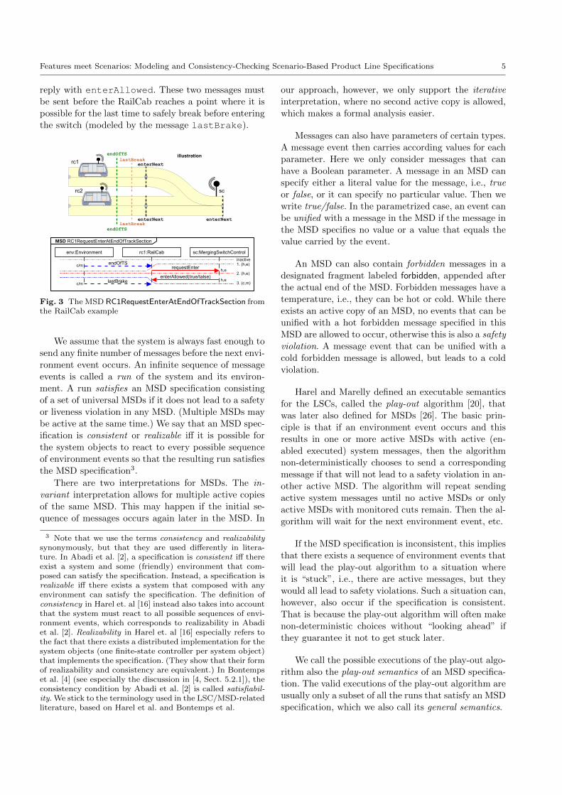
Features meet Scenarios: Modeling and Consistency-Checking Scenario-Based Product Line Specifications 5
reply with enterAllowed. These two messages must
be sent before the RailCab reaches a point where it is
possible for the last time to safely break before entering
the switch (modeled by the message lastBrake).
rc1
rc2 sc
illustrationendOfTSlastBreak
endOfTSlastBreak
enterNext
enterNext
enterNext
endOfTS
env:Environment rc1:RailCab sc:MergingSwitchControl
requestEnter
enterAllowed(true/talse)
MSD RC1RequestEnterAtEndOfTrackSection
lastBrake
1. (h,e)
2. (h,e)
3. (c,m)
inactive
h,e
h,ec/m
c/m
Fig. 3 The MSD RC1RequestEnterAtEndOfTrackSection fromthe RailCab example
We assume that the system is always fast enough to
send any finite number of messages before the next envi-
ronment event occurs. An infinite sequence of message
events is called a run of the system and its environ-
ment. A run satisfies an MSD specification consisting
of a set of universal MSDs if it does not lead to a safety
or liveness violation in any MSD. (Multiple MSDs may
be active at the same time.) We say that an MSD spec-
ification is consistent or realizable iff it is possible for
the system objects to react to every possible sequence
of environment events so that the resulting run satisfies
the MSD specification3.
There are two interpretations for MSDs. The in-
variant interpretation allows for multiple active copies
of the same MSD. This may happen if the initial se-
quence of messages occurs again later in the MSD. In
3 Note that we use the terms consistency and realizabilitysynonymously, but that they are used differently in litera-ture. In Abadi et al. [2], a specification is consistent iff thereexist a system and some (friendly) environment that com-posed can satisfy the specification. Instead, a specification isrealizable iff there exists a system that composed with anyenvironment can satisfy the specification. The definition ofconsistency in Harel et. al [16] instead also takes into accountthat the system must react to all possible sequences of envi-ronment events, which corresponds to realizability in Abadiet al. [2]. Realizability in Harel et. al [16] especially refers tothe fact that there exists a distributed implementation for thesystem objects (one finite-state controller per system object)that implements the specification. (They show that their formof realizability and consistency are equivalent.) In Bontempset al. [4] (see especially the discussion in [4, Sect. 5.2.1]), theconsistency condition by Abadi et al. [2] is called satisfiabil-ity. We stick to the terminology used in the LSC/MSD-relatedliterature, based on Harel et al. and Bontemps et al.
our approach, however, we only support the iterative
interpretation, where no second active copy is allowed,
which makes a formal analysis easier.
Messages can also have parameters of certain types.
A message event then carries according values for each
parameter. Here we only consider messages that can
have a Boolean parameter. A message in an MSD can
specify either a literal value for the message, i.e., true
or false, or it can specify no particular value. Then we
write true/false. In the parametrized case, an event can
be unified with a message in the MSD if the message in
the MSD specifies no value or a value that equals the
value carried by the event.
An MSD can also contain forbidden messages in a
designated fragment labeled forbidden, appended after
the actual end of the MSD. Forbidden messages have a
temperature, i.e., they can be hot or cold. While there
exists an active copy of an MSD, no events that can be
unified with a hot forbidden message specified in this
MSD are allowed to occur, otherwise this is also a safety
violation. A message event that can be unified with a
cold forbidden message is allowed, but leads to a cold
violation.
Harel and Marelly defined an executable semantics
for the LSCs, called the play-out algorithm [20], that
was later also defined for MSDs [26]. The basic prin-
ciple is that if an environment event occurs and this
results in one or more active MSDs with active (en-
abled executed) system messages, then the algorithm
non-deterministically chooses to send a corresponding
message if that will not lead to a safety violation in an-
other active MSD. The algorithm will repeat sending
active system messages until no active MSDs or only
active MSDs with monitored cuts remain. Then the al-
gorithm will wait for the next environment event, etc.
If the MSD specification is inconsistent, this implies
that there exists a sequence of environment events that
will lead the play-out algorithm to a situation where
it is “stuck”, i.e., there are active messages, but they
would all lead to safety violations. Such a situation can,
however, also occur if the specification is consistent.
That is because the play-out algorithm will often make
non-deterministic choices without “looking ahead” if
they guarantee it not to get stuck later.
We call the possible executions of the play-out algo-
rithm also the play-out semantics of an MSD specifica-
tion. The valid executions of the play-out algorithm are
usually only a subset of all the runs that satisfy an MSD
specification, which we also call its general semantics.
6 Joel Greenyer et al.
s00 s10
s01 s11
f
f
!f
!f
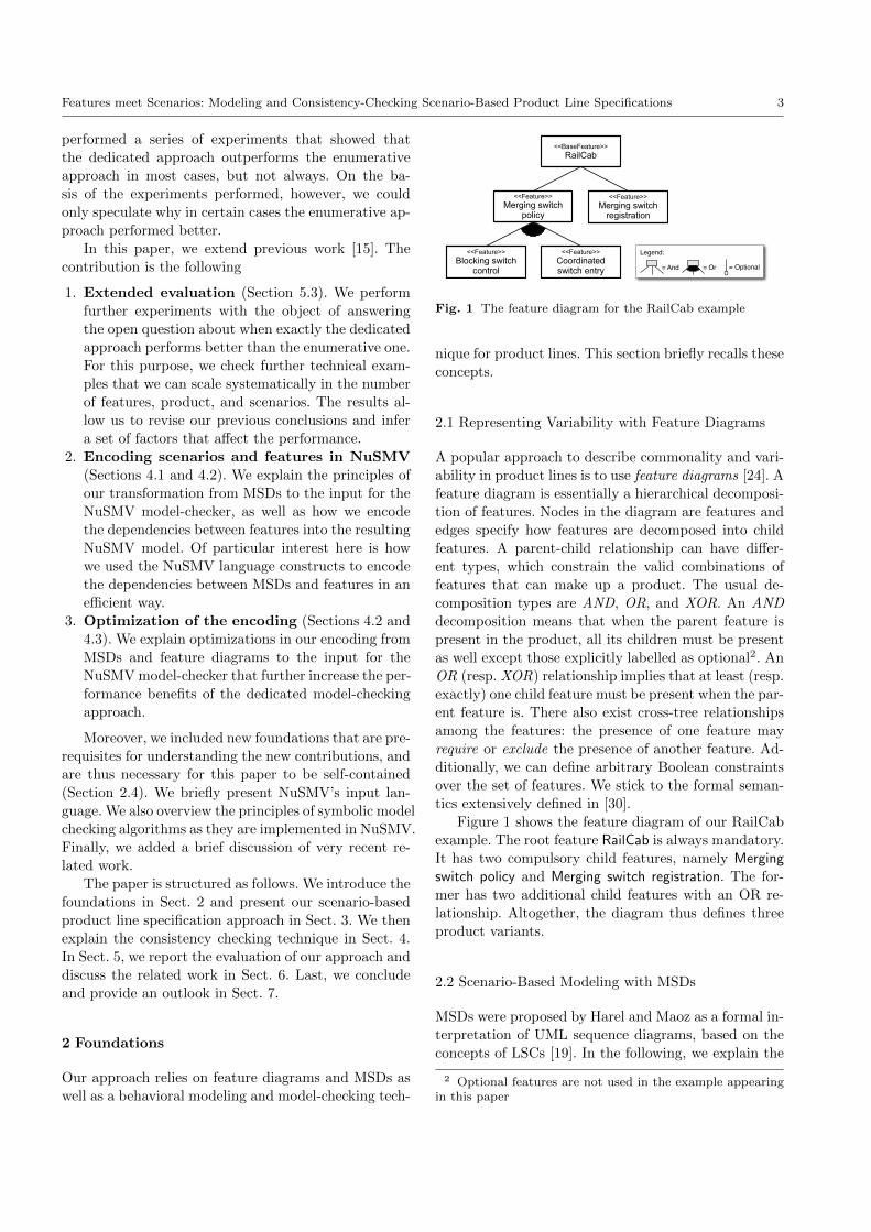
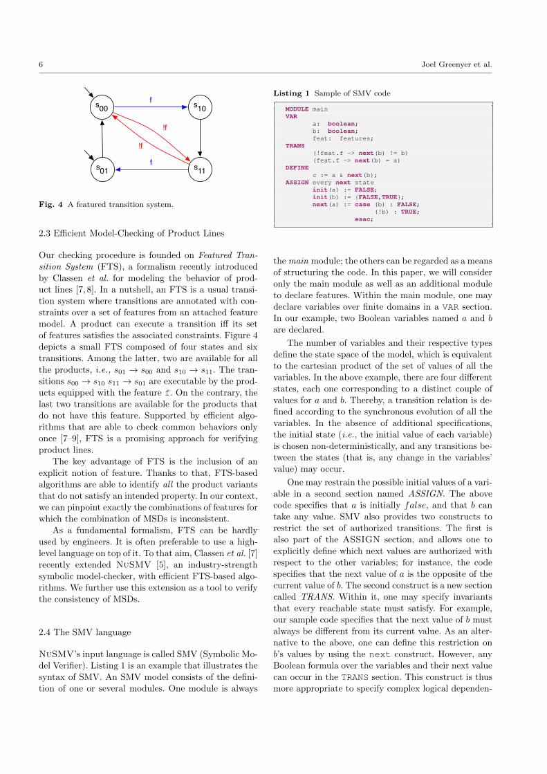
Fig. 4 A featured transition system.
2.3 Efficient Model-Checking of Product Lines
Our checking procedure is founded on Featured Tran-
sition System (FTS), a formalism recently introduced
by Classen et al. for modeling the behavior of prod-
uct lines [7, 8]. In a nutshell, an FTS is a usual transi-
tion system where transitions are annotated with con-
straints over a set of features from an attached feature
model. A product can execute a transition iff its set
of features satisfies the associated constraints. Figure 4
depicts a small FTS composed of four states and six
transitions. Among the latter, two are available for all
the products, i.e., s01 → s00 and s10 → s11. The tran-
sitions s00 → s10 s11 → s01 are executable by the prod-
ucts equipped with the feature f. On the contrary, the
last two transitions are available for the products that
do not have this feature. Supported by efficient algo-
rithms that are able to check common behaviors only
once [7–9], FTS is a promising approach for verifying
product lines.
The key advantage of FTS is the inclusion of an
explicit notion of feature. Thanks to that, FTS-based
algorithms are able to identify all the product variants
that do not satisfy an intended property. In our context,
we can pinpoint exactly the combinations of features for
which the combination of MSDs is inconsistent.
As a fundamental formalism, FTS can be hardly
used by engineers. It is often preferable to use a high-
level language on top of it. To that aim, Classen et al. [7]
recently extended NuSMV [5], an industry-strength
symbolic model-checker, with efficient FTS-based algo-
rithms. We further use this extension as a tool to verify
the consistency of MSDs.
2.4 The SMV language
NuSMV’s input language is called SMV (Symbolic Mo-
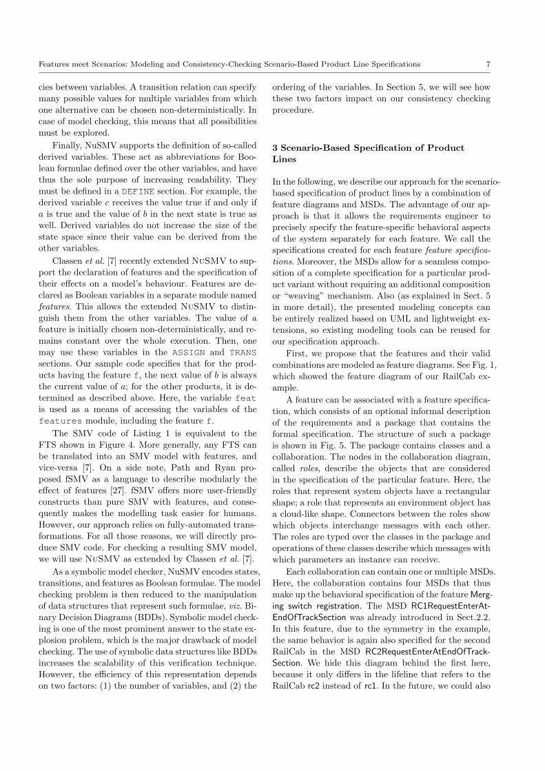
del Verifier). Listing 1 is an example that illustrates the
syntax of SMV. An SMV model consists of the defini-
tion of one or several modules. One module is always
Listing 1 Sample of SMV code
MODULE mainVAR
a: boolean;b: boolean;feat: features;
TRANS(!feat.f -> next(b) != b)(feat.f -> next(b) = a)
DEFINEc := a & next(b);
ASSIGN every next stateinit(a) := FALSE;init(b) := {FALSE,TRUE};next(a) := case (b) : FALSE;
(!b) : TRUE;esac;
the main module; the others can be regarded as a means
of structuring the code. In this paper, we will consider
only the main module as well as an additional module
to declare features. Within the main module, one may
declare variables over finite domains in a VAR section.
In our example, two Boolean variables named a and b
are declared.
The number of variables and their respective types
define the state space of the model, which is equivalent
to the cartesian product of the set of values of all the
variables. In the above example, there are four different
states, each one corresponding to a distinct couple of
values for a and b. Thereby, a transition relation is de-
fined according to the synchronous evolution of all the
variables. In the absence of additional specifications,
the initial state (i.e., the initial value of each variable)
is chosen non-deterministically, and any transitions be-
tween the states (that is, any change in the variables’
value) may occur.
One may restrain the possible initial values of a vari-
able in a second section named ASSIGN. The above
code specifies that a is initially false, and that b can
take any value. SMV also provides two constructs to
restrict the set of authorized transitions. The first is
also part of the ASSIGN section, and allows one to
explicitly define which next values are authorized with
respect to the other variables; for instance, the code
specifies that the next value of a is the opposite of the
current value of b. The second construct is a new section
called TRANS. Within it, one may specify invariants
that every reachable state must satisfy. For example,
our sample code specifies that the next value of b must
always be different from its current value. As an alter-
native to the above, one can define this restriction on
b’s values by using the next construct. However, any
Boolean formula over the variables and their next value
can occur in the TRANS section. This construct is thus
more appropriate to specify complex logical dependen-
Features meet Scenarios: Modeling and Consistency-Checking Scenario-Based Product Line Specifications 7
cies between variables. A transition relation can specify
many possible values for multiple variables from which
one alternative can be chosen non-deterministically. In
case of model checking, this means that all possibilities
must be explored.
Finally, NuSMV supports the definition of so-called
derived variables. These act as abbreviations for Boo-
lean formulae defined over the other variables, and have
thus the sole purpose of increasing readability. They
must be defined in a DEFINE section. For example, the
derived variable c receives the value true if and only if
a is true and the value of b in the next state is true as
well. Derived variables do not increase the size of the
state space since their value can be derived from the
other variables.
Classen et al. [7] recently extended NuSMV to sup-
port the declaration of features and the specification of
their effects on a model’s behaviour. Features are de-
clared as Boolean variables in a separate module named
features. This allows the extended NuSMV to distin-
guish them from the other variables. The value of a
feature is initially chosen non-deterministically, and re-
mains constant over the whole execution. Then, one
may use these variables in the ASSIGN and TRANSsections. Our sample code specifies that for the prod-
ucts having the feature f, the next value of b is always
the current value of a; for the other products, it is de-
termined as described above. Here, the variable featis used as a means of accessing the variables of the
features module, including the feature f.
The SMV code of Listing 1 is equivalent to the
FTS shown in Figure 4. More generally, any FTS can
be translated into an SMV model with features, and
vice-versa [7]. On a side note, Path and Ryan pro-
posed fSMV as a language to describe modularly the
effect of features [27]. fSMV offers more user-friendly
constructs than pure SMV with features, and conse-
quently makes the modelling task easier for humans.
However, our approach relies on fully-automated trans-
formations. For all those reasons, we will directly pro-
duce SMV code. For checking a resulting SMV model,
we will use NuSMV as extended by Classen et al. [7].
As a symbolic model checker, NuSMV encodes states,
transitions, and features as Boolean formulae. The model
checking problem is then reduced to the manipulation
of data structures that represent such formulae, viz. Bi-
nary Decision Diagrams (BDDs). Symbolic model check-
ing is one of the most prominent answer to the state ex-
plosion problem, which is the major drawback of model
checking. The use of symbolic data structures like BDDs
increases the scalability of this verification technique.
However, the efficiency of this representation depends
on two factors: (1) the number of variables, and (2) the
ordering of the variables. In Section 5, we will see how
these two factors impact on our consistency checking
procedure.
3 Scenario-Based Specification of Product
Lines
In the following, we describe our approach for the scenario-
based specification of product lines by a combination of
feature diagrams and MSDs. The advantage of our ap-
proach is that it allows the requirements engineer to
precisely specify the feature-specific behavioral aspects
of the system separately for each feature. We call the
specifications created for each feature feature specifica-
tions. Moreover, the MSDs allow for a seamless compo-
sition of a complete specification for a particular prod-
uct variant without requiring an additional composition
or “weaving” mechanism. Also (as explained in Sect. 5
in more detail), the presented modeling concepts can
be entirely realized based on UML and lightweight ex-
tensions, so existing modeling tools can be reused for
our specification approach.
First, we propose that the features and their valid
combinations are modeled as feature diagrams. See Fig. 1,
which showed the feature diagram of our RailCab ex-
ample.
A feature can be associated with a feature specifica-
tion, which consists of an optional informal description
of the requirements and a package that contains the
formal specification. The structure of such a package
is shown in Fig. 5. The package contains classes and a
collaboration. The nodes in the collaboration diagram,
called roles, describe the objects that are considered
in the specification of the particular feature. Here, the
roles that represent system objects have a rectangular
shape; a role that represents an environment object has
a cloud-like shape. Connectors between the roles show
which objects interchange messages with each other.
The roles are typed over the classes in the package and
operations of these classes describe which messages with
which parameters an instance can receive.
Each collaboration can contain one or multiple MSDs.
Here, the collaboration contains four MSDs that thus
make up the behavioral specification of the feature Merg-ing switch registration. The MSD RC1RequestEnterAt-EndOfTrackSection was already introduced in Sect.2.2.
In this feature, due to the symmetry in the example,
the same behavior is again also specified for the second
RailCab in the MSD RC2RequestEnterAtEndOfTrack-Section. We hide this diagram behind the first here,
because it only differs in the lifeline that refers to the
RailCab rc2 instead of rc1. In the future, we could also
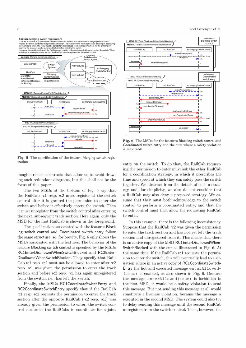
8 Joel Greenyer et al.
MSD RC2RegisterAndUnregister
MSD RC2RequestEnterAtEndOfTrackSection
Feature Merging switch registration:If a RailCab (rc1 or rc2) approaches the end of the track section and approaches a merging swtich, it must request the switch control for the permission to enter. The switch control must reply, either allowing or disallowing the RailCab to enter. The reply must be sent before the RailCab reaches the point where for the last time by applying the brakes it can be guranteed to halt before entering the switch.If entering the switch is allowed, the RailCab must register at the switch control before it enters the swtich. When entering the subsequent track section, the RailCab must unregister from the switch control.
endOfTS
env:Environment rc1:RailCab sc:MergingSwitchControl
requestEnter
enterAllowed(true/talse)
MSD RC1RequestEnterAtEndOfTrackSection
lastBrake
package Merging switch registration
Environment
MergingSwitchControl
requestEnter()
RailCab
endOfTS()enterAllowed( isAllowed:Boolean)lastBrake()
SwitchSystem
CollaborationSwitch System
rc2:RailCab
sc:MergingSwitchControl
env:Environment
rc1:RailCab
enterNext
env:Environment rc1:RailCab sc:MergingSwitchControl
MSD RC1RegisterAndUnregister
enterAllowed(true)
register
enterNextunregister
c,m
c,m
c,m
c,m
h,e
h,e
c,m
h,e
h,e
Fig. 5 The specification of the feature Merging switch regis-tration
imagine richer constructs that allow us to avoid draw-
ing such redundant diagrams, but this shall not be the
focus of this paper.
The two MSDs at the bottom of Fig. 5 say that
the RailCab rc1 resp. rc2 must register at the switch
control after it is granted the permission to enter the
switch and before it effectively enters the switch. Then
it must unregister from the switch control after entering
the next, subsequent track section. Here again, only the
MSD for the first RailCab is shown in the foreground.
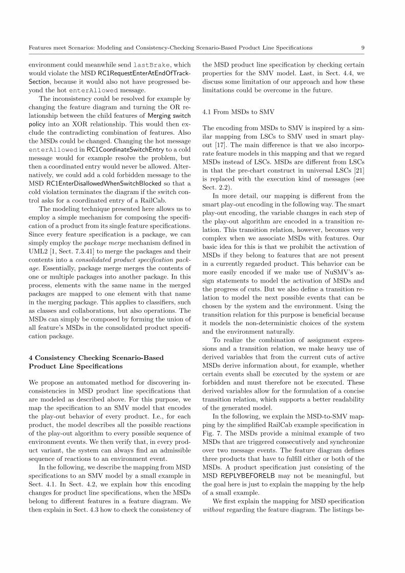
The specifications associated with the features Block-ing switch control and Coordinated switch entry follow
the same structure, so, for brevity, Fig. 6 only shows the
MSDs associated with the features. The behavior of the
feature Blocking switch control is specified by the MSDs
RC1EnterDisallowedWhenSwitchBlocked and RC2Enter-DisallowedWhenSwitchBlocked. They specify that Rail-
Cab rc1 resp. rc2 must not be allowed to enter after rc2resp. rc1 was given the permission to enter the track
section and before rc2 resp. rc1 has again unregistered
from the switch, i.e., has left the switch.
Finally, the MSDs RC1CoordinateSwitchEntry and
RC2CoordinateSwitchEntry specify that if the RailCab
rc1 resp. rc2 requests the permission to enter the track
section after the opposite RailCab (rc2 resp. rc1) was
already given the permission to enter, the switch con-
trol can order the RailCabs to coordinate for a joint
MSD RC2CoordinateSwitchEntry
MSD RC2EnterDisallowedWhenSwitchBlocked
enterAllowed(true)
rc1:RailCab rc2:RailCab sc:MergingSwitchControl
unregister
enterAllowed(true)
MSD RC1EnterDisallowedWhenSwitchBlocked
forbidden
<<Feature>>
Blocking switch control
rc1:RailCab rc2:RailCab sc:MergingSwitchControl
requestEnter
enterAllowed(true)
MSD RC1CoordinateSwitchEntry
coordinateEntry
requestStrategy()
coordinationStrategy()
ackCoordinatedEntry
unregisterforbidden
enterAllowed(true)
<<Feature>>
Coordinated switch entry
ackCoordinatedEntry
MSD RC1EnterDisallowedWhenSwitchBlocked
(c,m)
(h,e)
h,e
h,e
h,e
h,e
h,e
h,e
c
c,m
c,m
c,m
c,m
h
Fig. 6 The MSDs for the features Blocking switch control andCoordinated switch entry and the cuts where a safety violationis inevitable
entry on the switch. To do that, the RailCab request-
ing the permission to enter must ask the other RailCab
for a coordination strategy, in which it prescribes the
time and speed at which they can safely pass the switch
together. We abstract from the details of such a strat-
egy and, for simplicity, we also do not consider that
a RailCab may also deny a proposed strategy. We as-
sume that they must both acknowledge to the switch
control to perform a coordinated entry, and that the
switch control must then allow the requesting RailCab
to enter.
In this example, there is the following inconsistency.
Suppose that the RailCab rc2 was given the permission
to enter the track section and has not yet left the track
section and unregistered from it. This means that there
is an active copy of the MSD RC1EnterDisallowedWhen-SwitchBlocked with the cut as illustrated in Fig. 6. At
the same time, if the RailCab rc1 requests the permis-
sion to enter the switch, this will eventually lead to a sit-
uation where in an active copy of RC1CoordinateSwitch-Entry the hot and executed message enterAllowed-(true) is enabled, as also shown in Fig. 6. Because
the message enterAllowed(true) is forbidden in
the first MSD, it would be a safety violation to send
this message. But not sending this message at all would
constitute a liveness violation, because the message is
executed in the second MSD. The system could also try
to delay sending this message until the second RailCab
unregisters from the switch control. Then, however, the
Features meet Scenarios: Modeling and Consistency-Checking Scenario-Based Product Line Specifications 9
environment could meanwhile send lastBrake, which
would violate the MSD RC1RequestEnterAtEndOfTrack-Section, because it would also not have progressed be-
yond the hot enterAllowed message.
The inconsistency could be resolved for example by
changing the feature diagram and turning the OR re-
lationship between the child features of Merging switchpolicy into an XOR relationship. This would then ex-
clude the contradicting combination of features. Also
the MSDs could be changed. Changing the hot message
enterAllowed in RC1CoordinateSwitchEntry to a cold
message would for example resolve the problem, but
then a coordinated entry would never be allowed. Alter-
natively, we could add a cold forbidden message to the
MSD RC1EnterDisallowedWhenSwitchBlocked so that a
cold violation terminates the diagram if the switch con-
trol asks for a coordinated entry of a RailCab.
The modeling technique presented here allows us to
employ a simple mechanism for composing the specifi-
cation of a product from its single feature specifications.
Since every feature specification is a package, we can
simply employ the package merge mechanism defined in
UML2 [1, Sect. 7.3.41] to merge the packages and their
contents into a consolidated product specification pack-
age. Essentially, package merge merges the contents of
one or multiple packages into another package. In this
process, elements with the same name in the merged
packages are mapped to one element with that name
in the merging package. This applies to classifiers, such
as classes and collaborations, but also operations. The
MSDs can simply be composed by forming the union of
all feature’s MSDs in the consolidated product specifi-
cation package.
4 Consistency Checking Scenario-Based
Product Line Specifications
We propose an automated method for discovering in-
consistencies in MSD product line specifications that
are modeled as described above. For this purpose, we
map the specification to an SMV model that encodes
the play-out behavior of every product. I.e., for each
product, the model describes all the possible reactions
of the play-out algorithm to every possible sequence of
environment events. We then verify that, in every prod-
uct variant, the system can always find an admissible
sequence of reactions to an environment event.
In the following, we describe the mapping from MSD
specifications to an SMV model by a small example in
Sect. 4.1. In Sect. 4.2, we explain how this encoding
changes for product line specifications, when the MSDs
belong to different features in a feature diagram. We
then explain in Sect. 4.3 how to check the consistency of
the MSD product line specification by checking certain
properties for the SMV model. Last, in Sect. 4.4, we
discuss some limitation of our approach and how these
limitations could be overcome in the future.
4.1 From MSDs to SMV
The encoding from MSDs to SMV is inspired by a sim-
ilar mapping from LSCs to SMV used in smart play-
out [17]. The main difference is that we also incorpo-
rate feature models in this mapping and that we regard
MSDs instead of LSCs. MSDs are different from LSCs
in that the pre-chart construct in universal LSCs [21]
is replaced with the execution kind of messages (see
Sect. 2.2).
In more detail, our mapping is different from the
smart play-out encoding in the following way. The smart
play-out encoding, the variable changes in each step of
the play-out algorithm are encoded in a transition re-
lation. This transition relation, however, becomes very
complex when we associate MSDs with features. Our
basic idea for this is that we prohibit the activation of
MSDs if they belong to features that are not present
in a currently regarded product. This behavior can be
more easily encoded if we make use of NuSMV’s as-
sign statements to model the activation of MSDs and
the progress of cuts. But we also define a transition re-
lation to model the next possible events that can be
chosen by the system and the environment. Using the
transition relation for this purpose is beneficial because
it models the non-deterministic choices of the system
and the environment naturally.
To realize the combination of assignment expres-
sions and a transition relation, we make heavy use of
derived variables that from the current cuts of active
MSDs derive information about, for example, whether
certain events shall be executed by the system or are
forbidden and must therefore not be executed. These
derived variables allow for the formulation of a concise
transition relation, which supports a better readability
of the generated model.
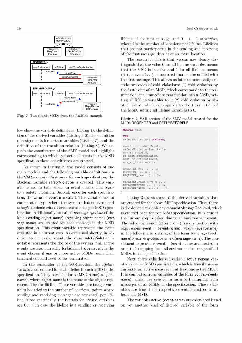
In the following, we explain the MSD-to-SMV map-
ping by the simplified RailCab example specification in
Fig. 7. The MSDs provide a minimal example of two
MSDs that are triggered consecutively and synchronize
over two message events. The feature diagram defines
three products that have to fulfill either or both of the
MSDs. A product specification just consisting of the
MSD REPLYBEFORELB may not be meaningful, but
the goal here is just to explain the mapping by the help
of a small example.
We first explain the mapping for MSD specification
without regarding the feature diagram. The listings be-
10 Joel Greenyer et al.
endOfTS
env:Environment rc:RailCab next:TrackSectionControl
requestEnter
enterAllowed(t/f)
REQENTER
lastBreak
env:Environment rc:RailCab next:TrackSectionControl
requestEnter
enterAllowed(t/f)
REPLYBEFORELB
<<Feature>>
ReplyBeforeLBFeature
<<Feature>>
ReqEnterFeature
<<BaseFeature>>
BaseFeature
<<Feature>>
ReqEnterFeature
<<Feature>>
ReplyBeforeLBFeature
Fig. 7 Two simple MSDs from the RailCab example
low show the variable definitions (Listing 2), the defini-
tion of the derived variables (Listing 3-6), the definition
of assignments for certain variables (Listing 7), and the
definition of the transition relation (Listing 8). We ex-
plain the constituents of the SMV model and highlight
corresponding to which syntactic elements in the MSD
specification these constituents are created.
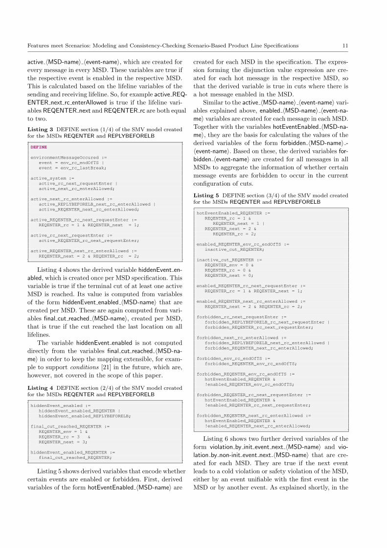
As shown in Listing 2, the model consists of one
main module and the following variable definitions (in
the VAR section): First, once for each specification, the
Boolean variable safetyViolation is created. This vari-
able is set to true when an event occurs that leads
to a safety violation. Second, once for each specifica-
tion, the variable event is created. This variable has an
enumerated type where the symbols hidden event and
safetyViolationInevitable are created once per MSD spec-
ification. Additionally, so-called message-symbols of the
kind 〈sending-object-name〉 〈receiving-object-name〉 〈mes-sage-name〉 are created for each message in the MSD
specification. This event variable represents the event
executed in a current step. As explained shortly, in ad-
dition to a message event, the value safetyViolationIn-evitable represents the choice of the system if all active
events are also currently forbidden. hidden event is the
event chosen if one or more active MSDs reach their
terminal cut and need to be terminated.
In the remainder of the VAR section, the lifeline
variables are created for each lifeline in each MSD in the
specification. They have the form 〈MSD-name〉 〈object-name〉, where object-name is the name of the object rep-
resented by the lifeline. These variables are integer vari-
ables bounded to the number of locations (points where
sending and receiving messages are attached) per life-
line. More specifically, the bounds for lifeline variables
are 0 . . . i in case the lifeline is a sending or receiving
lifeline of the first message and 0 . . . i + 1 otherwise,
where i is the number of locations per lifeline. Lifelines
that are not participating in the sending and receiving
of the first message thus have an extra location.
The reason for this is that we can now clearly dis-
tinguish that the value 0 for all lifeline variables means
that the MSD is inactive and 1 for all lifelines means
that an event has just occurred that can be unified with
the first message. This allows us later to more easily en-
code two cases of cold violations: (1) cold violation by
the first event of an MSD, which corresponds to the ter-
mination and immediate reactivation of an MSD, set-
ting all lifeline variables to 1; (2) cold violation by an-
other event, which corresponds to the termination of
the MSD, setting all lifeline variables to 0.
Listing 2 VAR section of the SMV model created for theMSDs REQENTER and REPLYBEFORELB
MODULE main
VARsafetyViolation: boolean;
event: { hidden_Event,safetyViolationInevitable,env_rc_endOfTS,rc_next_requestEnter,next_rc_enterAllowed,env_rc_lastBreak };
REQENTER_env: 0 .. 1;REQENTER_rc: 0 .. 3;REQENTER_next: 0 .. 3;
REPLYBEFORELB_env: 0 .. 2;REPLYBEFORELB_rc: 0 .. 3;REPLYBEFORELB_next: 0 .. 2;
Listing 3 shows some of the derived variables that
are created for the above MSD specification. First, there
is the derived variable environmentMessageOccurred, which
is created once for per MSD specification. It is true if
the current step is taken due to an environment event.
The value expression (after the =) is a disjunction with
expressions event = 〈event-name〉, where 〈event-name〉in the following is a string of the form 〈sending-object-name〉 〈receiving-object-name〉 〈message-name〉. The con-
stituent expressions event = 〈event-name〉 are created in
an n-to-1 mapping from all environment messages of all
MSDs in the specification.
Next, there is the derived variable active system, cre-
ated once per MSD specification, which is true if there is
currently an active message in at least one active MSD.
It is computed from variables of the form active 〈event-name〉, which are created in an n-to-1 mapping from
messages of all MSDs in the specification. These vari-
ables are true if the respective event is enabled in at
least one MSD.
The variables active 〈event-name〉 are calculated based
on yet another kind of derived variable of the form
Features meet Scenarios: Modeling and Consistency-Checking Scenario-Based Product Line Specifications 11
active 〈MSD-name〉 〈event-name〉, which are created for
every message in every MSD. These variables are true if
the respective event is enabled in the respective MSD.
This is calculated based on the lifeline variables of the
sending and receiving lifeline. So, for example active REQ-ENTER next rc enterAllowed is true if the lifeline vari-
ables REQENTER next and REQENTER rc are both equal
to two.
Listing 3 DEFINE section (1/4) of the SMV model createdfor the MSDs REQENTER and REPLYBEFORELB
DEFINE
environmentMessageOccured :=event = env_rc_endOfTS |event = env_rc_lastBreak;
active_system :=active_rc_next_requestEnter |active_next_rc_enterAllowed;
active_next_rc_enterAllowed :=active_REPLYBEFORELB_next_rc_enterAllowed |active_REQENTER_next_rc_enterAllowed;
active_REQENTER_rc_next_requestEnter :=REQENTER_rc = 1 & REQENTER_next = 1;
active_rc_next_requestEnter :=active_REQENTER_rc_next_requestEnter;
active_REQENTER_next_rc_enterAllowed :=REQENTER_next = 2 & REQENTER_rc = 2;
Listing 4 shows the derived variable hiddenEvent en-abled, which is created once per MSD specification. This
variable is true if the terminal cut of at least one active
MSD is reached. Its value is computed from variables
of the form hiddenEvent enabled 〈MSD-name〉 that are
created per MSD. These are again computed from vari-
ables final cut reached 〈MSD-name〉, created per MSD,
that is true if the cut reached the last location on alllifelines.
The variable hiddenEvent enabled is not computed
directly from the variables final cut reached 〈MSD-na-me〉 in order to keep the mapping extensible, for exam-
ple to support conditions [21] in the future, which are,
however, not covered in the scope of this paper.
Listing 4 DEFINE section (2/4) of the SMV model createdfor the MSDs REQENTER and REPLYBEFORELB
hiddenEvent_enabled :=hiddenEvent_enabled_REQENTER |hiddenEvent_enabled_REPLYBEFORELB;
final_cut_reached_REQENTER :=REQENTER_env = 1 &REQENTER_rc = 3 &REQENTER_next = 3;
hiddenEvent_enabled_REQENTER :=final_cut_reached_REQENTER;
Listing 5 shows derived variables that encode whether
certain events are enabled or forbidden. First, derived
variables of the form hotEventEnabled 〈MSD-name〉 are
created for each MSD in the specification. The expres-
sion forming the disjunction value expression are cre-
ated for each hot message in the respective MSD, so
that the derived variable is true in cuts where there is
a hot message enabled in the MSD.
Similar to the active 〈MSD-name〉 〈event-name〉 vari-
ables explained above, enabled 〈MSD-name〉 〈event-na-me〉 variables are created for each message in each MSD.
Together with the variables hotEventEnabled 〈MSD-na-me〉, they are the basis for calculating the values of the
derived variables of the form forbidden 〈MSD-name〉 -〈event-name〉. Based on these, the derived variables for-bidden 〈event-name〉 are created for all messages in all
MSDs to aggregate the information of whether certain
message events are forbidden to occur in the current
configuration of cuts.
Listing 5 DEFINE section (3/4) of the SMV model createdfor the MSDs REQENTER and REPLYBEFORELB
hotEventEnabled_REQENTER :=REQENTER_rc = 1 &
REQENTER_next = 1 |REQENTER_next = 2 &
REQENTER_rc = 2;
enabled_REQENTER_env_rc_endOfTS :=inactive_cut_REQENTER;
inactive_cut_REQENTER :=REQENTER_env = 0 &REQENTER_rc = 0 &REQENTER_next = 0;
enabled_REQENTER_rc_next_requestEnter :=REQENTER_rc = 1 & REQENTER_next = 1;
enabled_REQENTER_next_rc_enterAllowed :=REQENTER_next = 2 & REQENTER_rc = 2;
forbidden_rc_next_requestEnter :=forbidden_REPLYBEFORELB_rc_next_requestEnter |forbidden_REQENTER_rc_next_requestEnter;
forbidden_next_rc_enterAllowed :=forbidden_REPLYBEFORELB_next_rc_enterAllowed |forbidden_REQENTER_next_rc_enterAllowed;
forbidden_env_rc_endOfTS :=forbidden_REQENTER_env_rc_endOfTS;
forbidden_REQENTER_env_rc_endOfTS :=hotEventEnabled_REQENTER &!enabled_REQENTER_env_rc_endOfTS;
forbidden_REQENTER_rc_next_requestEnter :=hotEventEnabled_REQENTER &!enabled_REQENTER_rc_next_requestEnter;
forbidden_REQENTER_next_rc_enterAllowed :=hotEventEnabled_REQENTER &!enabled_REQENTER_next_rc_enterAllowed;
Listing 6 shows two further derived variables of the
form violation by init event next 〈MSD-name〉 and vio-lation by non-init event next 〈MSD-name〉 that are cre-
ated for each MSD. They are true if the next event
leads to a cold violation or safety violation of the MSD,
either by an event unifiable with the first event in the
MSD or by another event. As explained shortly, in the
12 Joel Greenyer et al.
case of a cold violation by the first event, all lifeline
variables for this MSD will be reset to one: in case of a
cold violation by another event, all lifeline variables for
this MSD will be reset to zero.
Note that a range of derived variables that are cre-
ated specifically for the MSD REPLYBEFORELB are
omitted here.
Listing 6 DEFINE section (4/4) of the SMV model createdfor the MSDs REQENTER and REPLYBEFORELB
violation_by_init_event_next_REQENTER :=next(event) = env_rc_endOfTS &!enabled_REQENTER_env_rc_endOfTS;
violation_by_non-init_event_next_REQENTER :=next(event) = rc_next_requestEnter &
!enabled_REQENTER_rc_next_requestEnter |next(event) = next_rc_enterAllowed &
!enabled_REQENTER_next_rc_enterAllowed);
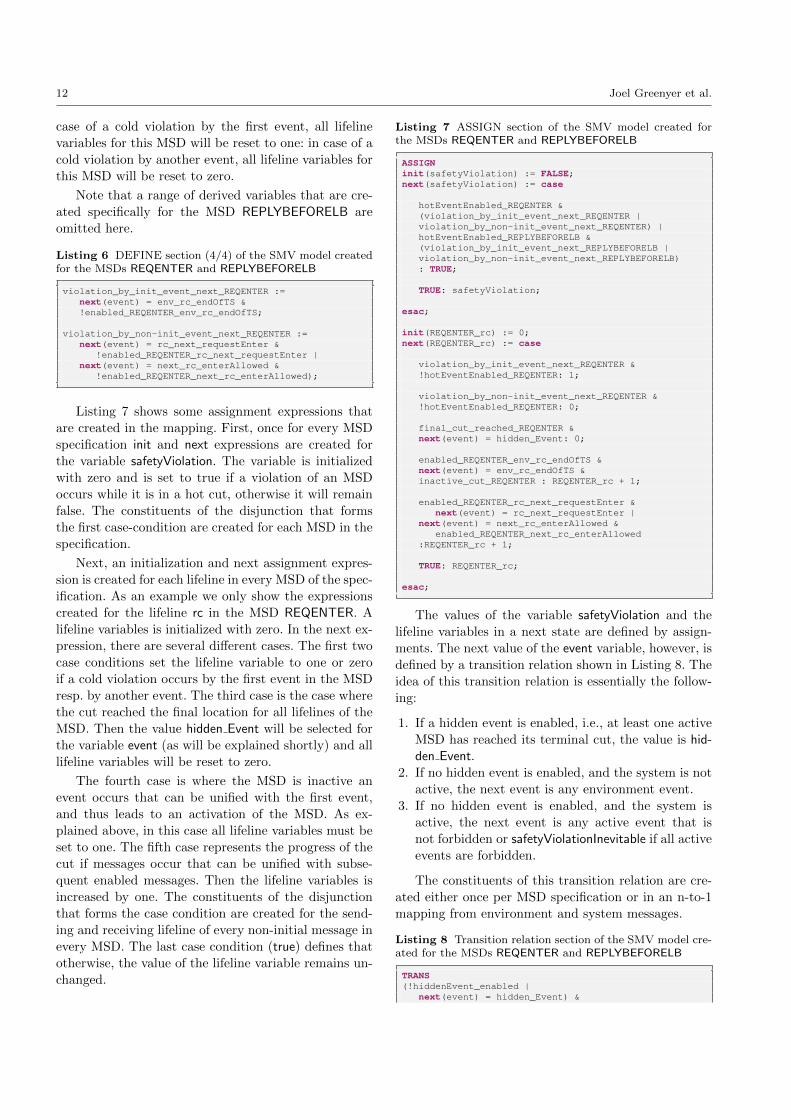
Listing 7 shows some assignment expressions that
are created in the mapping. First, once for every MSD
specification init and next expressions are created for
the variable safetyViolation. The variable is initialized
with zero and is set to true if a violation of an MSD
occurs while it is in a hot cut, otherwise it will remain
false. The constituents of the disjunction that forms
the first case-condition are created for each MSD in the
specification.
Next, an initialization and next assignment expres-
sion is created for each lifeline in every MSD of the spec-
ification. As an example we only show the expressions
created for the lifeline rc in the MSD REQENTER. A
lifeline variables is initialized with zero. In the next ex-
pression, there are several different cases. The first two
case conditions set the lifeline variable to one or zero
if a cold violation occurs by the first event in the MSD
resp. by another event. The third case is the case where
the cut reached the final location for all lifelines of the
MSD. Then the value hidden Event will be selected for
the variable event (as will be explained shortly) and all
lifeline variables will be reset to zero.
The fourth case is where the MSD is inactive an
event occurs that can be unified with the first event,
and thus leads to an activation of the MSD. As ex-
plained above, in this case all lifeline variables must be
set to one. The fifth case represents the progress of the
cut if messages occur that can be unified with subse-
quent enabled messages. Then the lifeline variables is
increased by one. The constituents of the disjunction
that forms the case condition are created for the send-
ing and receiving lifeline of every non-initial message in
every MSD. The last case condition (true) defines that
otherwise, the value of the lifeline variable remains un-
changed.
Listing 7 ASSIGN section of the SMV model created forthe MSDs REQENTER and REPLYBEFORELB
ASSIGNinit(safetyViolation) := FALSE;next(safetyViolation) := case
hotEventEnabled_REQENTER &(violation_by_init_event_next_REQENTER |violation_by_non-init_event_next_REQENTER) |hotEventEnabled_REPLYBEFORELB &(violation_by_init_event_next_REPLYBEFORELB |violation_by_non-init_event_next_REPLYBEFORELB): TRUE;
TRUE: safetyViolation;
esac;
init(REQENTER_rc) := 0;next(REQENTER_rc) := case
violation_by_init_event_next_REQENTER &!hotEventEnabled_REQENTER: 1;
violation_by_non-init_event_next_REQENTER &!hotEventEnabled_REQENTER: 0;
final_cut_reached_REQENTER &next(event) = hidden_Event: 0;
enabled_REQENTER_env_rc_endOfTS &next(event) = env_rc_endOfTS &inactive_cut_REQENTER : REQENTER_rc + 1;
enabled_REQENTER_rc_next_requestEnter &next(event) = rc_next_requestEnter |
next(event) = next_rc_enterAllowed &enabled_REQENTER_next_rc_enterAllowed
:REQENTER_rc + 1;
TRUE: REQENTER_rc;
esac;
The values of the variable safetyViolation and the
lifeline variables in a next state are defined by assign-
ments. The next value of the event variable, however, is
defined by a transition relation shown in Listing 8. The
idea of this transition relation is essentially the follow-
ing:
1. If a hidden event is enabled, i.e., at least one active
MSD has reached its terminal cut, the value is hid-den Event.
2. If no hidden event is enabled, and the system is not
active, the next event is any environment event.
3. If no hidden event is enabled, and the system is
active, the next event is any active event that is
not forbidden or safetyViolationInevitable if all active
events are forbidden.
The constituents of this transition relation are cre-
ated either once per MSD specification or in an n-to-1
mapping from environment and system messages.
Listing 8 Transition relation section of the SMV model cre-ated for the MSDs REQENTER and REPLYBEFORELB
TRANS(!hiddenEvent_enabled |
next(event) = hidden_Event) &
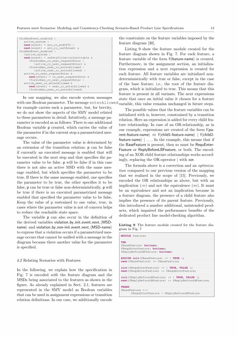
Features meet Scenarios: Modeling and Consistency-Checking Scenario-Based Product Line Specifications 13
(hiddenEvent_enabled |active_system |next(event) = env_rc_endOfTS |next(event) = env_rc_lastBreak) &
(hiddenEvent_enabled |!active_system |next(event) = safetyViolationInevitable &
(forbidden_rc_next_requestEnter |!active_rc_next_requestEnter) &
(forbidden_next_rc_enterAllowed |!active_next_rc_enterAllowed) |
active_rc_next_requestEnter &next(event) = rc_next_requestEnter &!forbidden_rc_next_requestEnter |
active_next_rc_enterAllowed &next(event) = next_rc_enterAllowed &!forbidden_next_rc_enterAllowed)
In our mapping, we also encode system messages
with one Boolean parameter. The message enterAllowedfor example carries such a parameter, but, for brevity,
we do not show the aspects of the SMV model related
to these parameters in detail. Intuitively, a message pa-
rameter is encoded as as follows: There is one additional
Boolean variable p created, which carries the value of
the parameter if in the current step a parametrized mes-
sage occurs.
The value of the parameter value is determined by
an extension of the transition relation: p can be false
if currently an executed message is enabled that will
be executed in the next step and that specifies the pa-
rameter value to be false. p will be false if in this case
there is not also an active MSD with the same mes-
sage enabled, but which specifies the parameter to be
true. If there is the same message enabled, one specifies
the parameter to be true, the other specifies it to be
false, p can be true or false non-deterministically. p will
be true if there is no executed parametrized message
enabled that specified the parameter value to be false.
Keep the value of p restrained to one value, true, in
cases where the parameter value is not of concern helps
to reduce the reachable state space.
The variable p can also occur in the definition of
the derived variables violation by init event next 〈MSD-name〉 and violation by non-init event next 〈MSD-name〉to express that a violation occurs if a parametrized mes-
sage occurs that cannot be unified with a message in the
diagram because there another value for the parameter
is specified.
4.2 Relating Scenarios with Features
In the following, we explain how the specification in
Fig. 7 is encoded with the feature diagram and the
MSDs being associated to the features as shown in the
figure. As already explained in Sect. 2.1, features are
represented in the SMV model as Boolean variables
that can be used in assignment expressions or transition
relation definitions. In our case, we additionally encode
the constraints on the feature variables imposed by the
feature diagram [30].
Listing 9 show the feature module created for the
feature diagram shown in Fig. 7. For each feature, a
feature variable of the form f〈feature-name〉 is created.
Furthermore, in the assignment section, an initializa-
tion expression and a next expression is created for
each feature. All feature variables are initialized non-
deterministically with true or false, except in the case
of the base feature, i.e., the root of the feature dia-
gram, which is initialized to true. This means that this
feature is present in all variants. The next expressions
state that once an initial value it chosen for a feature
variable, this value remains unchanged in future steps.
The possible values that the feature variables can be
initialized with is, however, constrained by a transition
relation. Here an expression is added for every child fea-
ture relationship. In case of an OR-relationship, as in
our example, expressions are created of the form f〈pa-rent-feature-name〉 ⇔ f〈child1-feature-name〉 | f〈child2-feature-name〉 | . . . . In the example, this means that if
the BaseFeature is present, then so must be RequEnter-Feature or ReplyBeforeLBFeature, or both. The encod-
ing of an XOR child feature relationships works accord-
ingly, replacing the OR-operator | with xor.
The formula above is a correction and an optimiza-
tion compared to our previous version of the mapping
that we realized in the scope of [15]. Previously, we
encoded the OR relationships as above, but with an
implication (⇒) and not the equivalence (⇔). It must
be an equivalence and not an implication because in
a feature diagram, the presence of a child feature also
implies the presence of its parent feature. Previously,this introduced a number additional, unintended prod-
ucts, which impaired the performance benefits of the
dedicated product line model-checking algorithm.
Listing 9 The feature module created for the feature dia-gram in Fig. 7
MODULE features
VARfBaseFeature: boolean;fRequEnterFeature: boolean;fReplyBeforeLBFeature: boolean;
ASSIGN init(fBaseFeature) := { TRUE };next(fBaseFeature) := fBaseFeature;
init(fRequEnterFeature) := { TRUE, FALSE };next(fRequEnterFeature) := fRequEnterFeature;
init(fReplyBeforeLBFeature) := { TRUE, FALSE };next(fReplyBeforeLBFeature) := fReplyBeforeLBFeature;
TRANSfBaseFeature <->
fRequEnterFeature | fReplyBeforeLBFeature
14 Joel Greenyer et al.
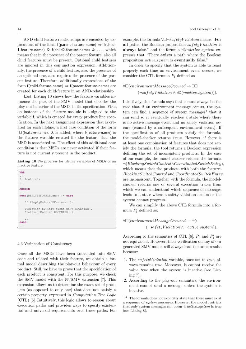
AND child feature relationships are encoded by ex-
pressions of the form f〈parent-feature-name〉 ⇒ f〈child-1-feature-name〉 & f〈child2-feature-name〉 & . . . , which
means that in the presence of the parent feature, also all
child features must be present. Optional child features
are ignored in this conjunction expression. Addition-
ally, the presence of a child feature, also the presence of
an optional one, also requires the presence of the par-
ent feature. Therefore, additionally expressions of the
form f〈child-feature-name〉 ⇒ f〈parent-feature-name〉 are
created for each child-feature in an AND-relationship.
Last, Listing 10 shows how the feature variables in-
fluence the part of the SMV model that encodes the
play-out behavior of the MSDs in the specification. First,
an instance of the feature module is assigned to the
variable f, which is created for every product line spec-
ification. In the next assignment expression that is cre-
ated for each lifeline, a first case condition of the form
!f.f〈feature-name〉: 0; is added, where f〈feature-name〉 is
the feature variable created for the feature that the
MSD is associated to. The effect of this additional case
condition is that MSDs are never activated if their fea-
ture is not currently present in the product.
Listing 10 No progress for lifeline variables of MSDs of aninactive feature
VAR...f: features;...
ASSIGN...next(REPLYBEFORELB_env) := case
!f.fReplyBeforeLBFeature: 0;
violation_by_init_event_next_REQENTER &!hotEventEnabled_REQENTER: 1;
...esac;...
4.3 Verification of Consistency
Once all the MSDs have been translated into SMV
code and related with their feature, we obtain a for-
mal model describing the play-out behaviour of every
product. Still, we have to prove that the specification of
each product is consistent. For this purpose, we check
the SMV model with the NuSMV extension [7]. This
extension allows us to determine the exact set of prod-
ucts (as opposed to only one) that does not satisfy a
certain property, expressed in Computation Tree Logic
(CTL) [6]. Intuitively, this logic allows to reason about
execution paths and provides ways to specify existen-
tial and universal requirements over these paths. For
example, the formula ∀�¬safetyV iolation means “For
all paths, the Boolean proposition safetyV iolation is
always false.” and the formula ∃♦¬active system ex-
presses that “There exists a path where the Boolean
proposition active system is eventually false.”
In order to specify that the system is able to react
properly each time an environment event occurs, we
consider the CTL formula P1 defined as
∀�(environmentMessageOccured→ ∃�(¬safetyV iolation ∧ ∃♦(¬active system))).
Intuitively, this formula says that it must always be the
case that if an environment message occurs, the sys-
tem can find a sequence of system messages4 that it
can send so it eventually reaches a state where there
is no active message event and no safety violation oc-
curs (caused by a subsequent environment event). If
the specification of all products satisfy the formula,
the model-checker returns True. However, if there is
at least one combination of features that does not sat-
isfy the formula, the tool returns a Boolean expression
defining the set of inconsistent products. In the case
of our example, the model-checker returns the formula
¬(BlockingSwitchControl∧CoordinatedSwitchEntry),
which means that the products with both the features
BlockingSwitchControl and CoordinatedSwitchEntry
are inconsistent. Together with the formula, the model-
checker returns one or several execution traces from
which we can understand which sequence of messages
leads to a state where a safety violation occurs or the
system cannot progress.
We can simplify the above CTL formula into a for-
mula P ′1 defined as:
∀�(environmentMessageOccured→ ∃♦(¬safetyV iolation ∧ ¬active system)).
According to the semantics of CTL [6], P1 and P ′1 are
not equivalent. However, their verification on any of our
generated SMV model will always lead the same results
because:
1. The safetyV iolation variable, once set to true, al-
ways remains true. Moreover, it cannot receive the
value true when the system is inactive (see List-
ing 7).
2. According to the play-out semantics, the environ-
ment cannot send a message unless the system is
inactive.
4 The formula does not explicitly state that there must exista sequence of system messages. However, the model restrictsthat only system messages can occur if active system is true(see Listing 8).
Features meet Scenarios: Modeling and Consistency-Checking Scenario-Based Product Line Specifications 15
Thus, P ′1 is an appropriate alternative to P1. It is also
more concise and easy to understand. During our ex-
periments (further described in Section 5.3), however,
we observed that checking P ′1 instead of P1 only leads
to negligible variations in performance. Consequently,
we stick to P1 in the rest of this paper.
4.4 Discussion
Our approach has a number of restrictions. First of all,
the SMV model encodes the play-out semantics of the
MSD specification. This means that we consider that a
system can only send messages that correspond to exe-
cuted message currently enabled in an active MSD—the
system cannot decide to send other messages or not to
execute an enabled executed message. This restriction is
necessary for our approach to remain feasible. Further-
more, it is a meaningful restriction, because we only
consider the execution of messages that are explicitly
marked to be executed. Anything else may even be re-
garded as an unintended behavior by the requirements
engineer. However, it makes the approach incomplete,
i.e., there may be a system that behaves differently than
the play-out algorithm, but implements the specifica-
tion.
Furthermore, the property P1 checks that from a
state where an environment message occurred, the sys-
tem can find a valid sequence of system messages in
reaction to that event. But if there does not exist such
a reaction, it will not consider if it could have avoided
that state by choosing another order among steps in a
previous sequence of system messages that it sent in re-
action to some earlier environment event. This require-
ment cannot be expressed in CTL, which motivates the
need for extending our approach: we would have to view
the problem as an infinite two-player game [4,14].
Harel et al. show that, if it can be ensured that every
execution of play-out avoids safety violation or getting
stuck, then statecharts can be transformed from the
scenarios for every object in the system [18]. With our
approach, we can also prove an according property P2:
∀�(¬safetyV iolation ∧ ∀♦(¬system is active)).
Note that the previous formula is weaker than this one.
When it is satisfied, it means that we can refine the
specification so that the other formula is satisfied as
well. Inspired by the synthesis method of Harel et al.,
we can thus provide RE engineers with automated tech-
niques for deriving implementations for product lines.
The derivation of state-charts is, however, out of the
scope of the current paper.
The correctness of our mapping in combination with
the above formulae, i.e., that the constructed model-
checking problem correctly encodes the consistency-checking
problem, is hard to prove. To validate the correctness
of the encoding, we conducted tests with a number of
small product line specifications which we designed to
be consistent or to contain certain kinds of inconsisten-
cies. In all the tests, the model checker returned the
expected results.
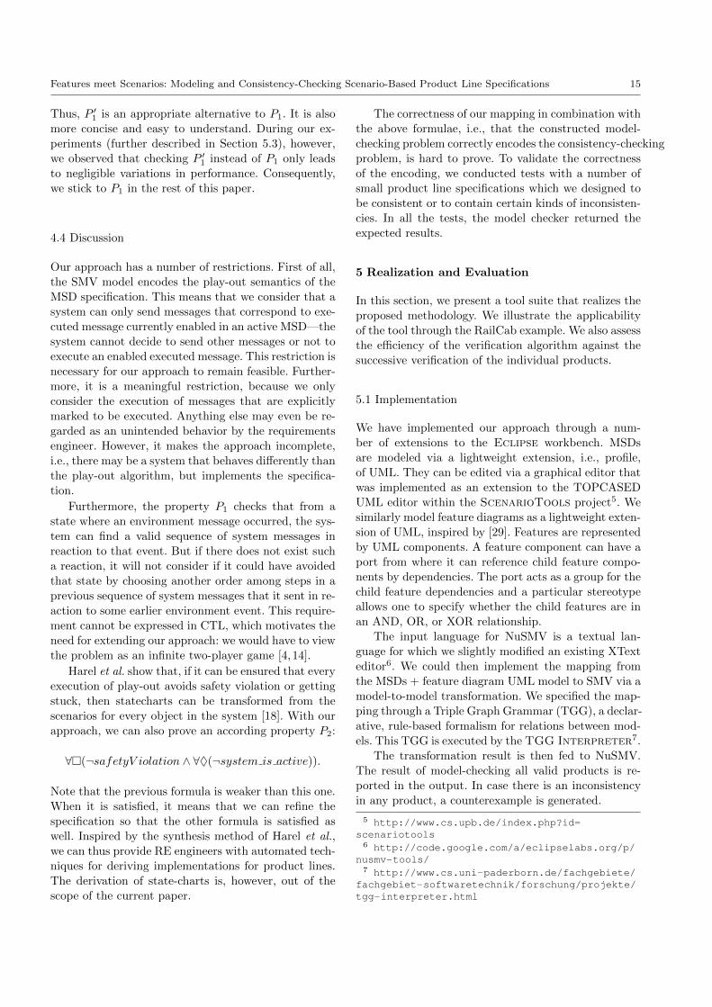
5 Realization and Evaluation
In this section, we present a tool suite that realizes the
proposed methodology. We illustrate the applicability
of the tool through the RailCab example. We also assess
the efficiency of the verification algorithm against the
successive verification of the individual products.
5.1 Implementation
We have implemented our approach through a num-
ber of extensions to the Eclipse workbench. MSDs
are modeled via a lightweight extension, i.e., profile,
of UML. They can be edited via a graphical editor that
was implemented as an extension to the TOPCASED
UML editor within the ScenarioTools project5. We
similarly model feature diagrams as a lightweight exten-
sion of UML, inspired by [29]. Features are represented
by UML components. A feature component can have a
port from where it can reference child feature compo-
nents by dependencies. The port acts as a group for the
child feature dependencies and a particular stereotype
allows one to specify whether the child features are in
an AND, OR, or XOR relationship.
The input language for NuSMV is a textual lan-
guage for which we slightly modified an existing XText
editor6. We could then implement the mapping from
the MSDs + feature diagram UML model to SMV via a
model-to-model transformation. We specified the map-
ping through a Triple Graph Grammar (TGG), a declar-
ative, rule-based formalism for relations between mod-
els. This TGG is executed by the TGG Interpreter7.
The transformation result is then fed to NuSMV.
The result of model-checking all valid products is re-
ported in the output. In case there is an inconsistency
in any product, a counterexample is generated.
5 http://www.cs.upb.de/index.php?id=scenariotools6 http://code.google.com/a/eclipselabs.org/p/
nusmv-tools/7 http://www.cs.uni-paderborn.de/fachgebiete/
fachgebiet-softwaretechnik/forschung/projekte/tgg-interpreter.html

16 Joel Greenyer et al.
Instructions to download and install our implemen-
tation can be found on our website 8.
5.2 Application to the RailCab Example
We applied our methodology to model and verify the
consistency of the RailCab example. As presented in
Section 3, the product exhibiting all the features is in-
consistent, because the MSDs RC1EnterDisallowedWhen-SwitchBlocked and RC1CoordinateSwitchEntry are incom-
patible.
We modeled this example in our tool, produced the
corresponding SMV model, and subsequently fed the
model into the NuSMV extension. When we verified
the model against the formula P1 (see Section 4.3),
NuSMV identified the inconsistent product and the
execution trace illustrating the violation. According to
this trace, we must avoid the following sequence of
events : envendOfTS−−−−−−−→ rc2, rc2
requestEnter−−−−−−−−−−→ sc,
scenterAllowed−−−−−−−−−−→ rc2, rc2
register−−−−−−→ sc, envendOfTS−−−−−−−→ rc1.
It means that if rc1 reaches the track section while rc2
is between rc1 and the switch, it is impossible for the
system to ensure the satisfaction of all the specifications
regardless of the (uncontrolled) environment events.
We decided to change the feature model in order
to forbid this combination of features. To that aim, we
replaced the OR relationship between the two features
with a XOR relationship. Once this is done, NuSMV
does not notice a violation of formula P1 anymore, nei-
ther of the formula P2. Hence, the play-out of the MSD
specification for any remaining product will never run
into any violation.
5.3 Performance Evaluation
Although checking the consistency of our running ex-
ample takes less than a second, this verification proce-
dure can be very time-consuming for larger models. The
selection of a specific algorithm and its optimizations
is thus of utmost importance. As stated by Classen et
al. [7, 8], there are two methods for model checking an
FTS. The first one, the enumerative approach consists
in deriving, from the FTS, the models corresponding to
each of the valid products and then verifying them in-
dividually. The second method, the dedicated approach,
relies on the dedicated algorithms proposed by Classen
et al.. A first and very significant advantage of the ded-
icated approach is that at the end of the verification, it
returns a concise formula that expresses which features
8 http://info.fundp.ac.be/fts/implementations/msd2smv
create inconsistencies in the MSD specifications. In con-
trast to the enumerative approach, this allows engineers
to clearly observe which feature combinations cannot be
realized.
What remains to evaluate is the relative performance
of the two approaches. The enumerative approach ver-
ifies a behavior common to several products as many
times as the number of products that exhibit this be-
havior; this is a major threat to performance and scal-
ability, especially given that the number of products
is, in the worst case, exponential in the number of fea-
tures. On the contrary, the dedicated approach checks
common behavior only once. However, it requires the
introduction of additional variables (one per feature).
Classen et al. showed that their extension of NuSMV
often overcomes an enumerative application of the stan-
dard NuSMV algorithm, but not always. It is thus im-
portant to evaluate whether this approach is appropri-
ate for our own purpose and under which conditions it
is better than the other approach. Moreover, although
we do not optimize the algorithm of Classen et al. [7]
per se, we improve it by automatically encoding the fea-
ture interdependencies defined by the feature diagram
as part of the SMV model. This encoding makes the
verification procedure ignore execution paths available
to invalid products only, and thus increases its overall
performance.
Our evaluation focuses on the following research
questions:
1. What is the most efficient approach to check the
consistency of MSD specifications? How do factors
like number of products and number of MSDs affect
the performance of these two algorithms?
2. Is is possible to automatically derive an efficient
variable ordering from the MSD specifications and
the structure of the feature diagram? Is this order-
ing pattern more efficient than NuSMV’s native dy-
namic reordering?
In the following experiments, we compare the time needed
by both algorithms to verify the SMV models against
formulae P1 and P2. To obtain the SMV model related
to a particular product, we first remove the declaration
of the feature variables in the original model. Then,
we replace every feature variable by true if the feature
belongs to the considered product, and by false oth-
erwise. In the subsequent evaluations, we do not count
the time needed for computing these individual models.
5.3.1 Previous results and open questions
In our previous work [15], we conducted experiments
with a technical example as also documented in this
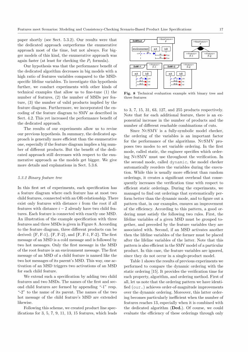
Features meet Scenarios: Modeling and Consistency-Checking Scenario-Based Product Line Specifications 17
paper shortly (see Sect. 5.3.2). Our results were that
the dedicated approach outperforms the enumerative
approach most of the time, but not always. For big-
ger models of this kind, the enumerative approach was
again faster (at least for checking the P1 formula).
Our hypothesis was that the performance benefit of
the dedicated algorithm decreases in big models with a
high ratio of features variables compared to the MSD-
specific lifeline variables. To investigate this hypothesis
further, we conduct experiments with other kinds of
technical examples that allow us to fine-tune (1) the
number of features, (2) the number of MSDs per fea-
ture, (3) the number of valid products implied by the
feature diagram. Furthermore, we incorporated the en-
coding of the feature diagram to SMV as described in
Sect. 4.2. This yet increased the performance benefit of
the dedicated approach.
The results of our experiments allow us to revise
our previous hypothesis. In summary, the dedicated ap-
proach is generally more efficient than the enumerative
one, especially if the feature diagram implies a big num-
ber of different products. But the benefit of the dedi-
cated approach still decreases with respect to the enu-
merative approach as the models get bigger. We give
more details and explanations in Sect. 5.3.6.
5.3.2 Binary feature tree
In this first set of experiments, each specification has
a feature diagram where each feature has at most two
child features, connected with an OR-relationship. There
exist only features with distance i from the root if all
features with distance i− 2 already have two child fea-
tures. Each feature is connected with exactly one MSD.
An illustration of the example specification with three
features and three MSDs is given in Figure 8. According
to the feature diagram, three different products can be
derived: {F, F-1}, {F, F-2}, and {F, F-1, F-2}. The first
message of an MSD is a cold message and is followed by
two hot messages. Only the first message in the MSD
of the root feature is an environment message. The first
message of an MSD of a child feature is named like the
two hot messages of its parent’s MSD. This way, one ac-
tivation of an MSD triggers two activations of an MSD
for each child feature.
We extend such a specification by adding two child
features and two MSDs. The names of the first and sec-
ond child features are formed by appending “-1” resp.
“-2” to the name of its parent. The names of the two
hot message of the child feature’s MSD are extended
likewise.
Following this scheme, we created product line spec-
ifications for 3, 5, 7, 9, 11, 13, 15 features, which leads
do
env:Environment a:A b:B
DoMRoot
m
m
m
a:A b:B
DoM1-1
m-1
m-1
m
a:A b:B
DoM1-2
m-2
m-2
<<Feature>>
F-2<<Feature>>
F-1
<<BaseFeature>>
F
<<BaseFeature>>
F
<<Feature>>
F-1<<Feature>>
F-2
h,e
h,e
c,m
h,e
h,e
c,m
c,mh,e
h,e
Fig. 8 Technical evaluation example with binary tree andthree features
to 3, 7, 15, 31, 63, 127, and 255 products respectively.
Note that for each additional feature, there is an ex-
ponential increase in the number of products and the
number of different reachable combinations of cuts.
Since NuSMV is a fully-symbolic model checker,
the ordering of the variables is an important factor
for the performance of the algorithms. NuSMV pro-
poses two modes to set variable ordering. In the first
mode, called static, the engineer specifies which order-
ing NuSMV must use throughout the verification. In
the second mode, called dynamic, the model checker
automatically reorders the variables during the execu-
tion. While this is usually more efficient than random
orderings, it creates a significant overhead that conse-
quently increases the verification time with respect to
efficient static orderings. During the experiments, we
managed to find out orderings that systematically per-
form better than the dynamic mode, and to figure out a
pattern that, in our examples, ensures an improvement
of the efficiency. According to this pattern, a good or-
dering must satisfy the following two rules. First, the
lifeline variables of a given MSD must be grouped to-
gether, and preceded by the feature variables they are
associated with. Second, if an MSD activates another
then the lifeline variables of the former must be placed
after the lifeline variables of the latter. Note that this
pattern is also efficient in the SMV model of a particular
product. In this case, the feature variables are ignored,
since they do not occur in a single-product model.
Table 1 shows the results of previous experiments we
performed to compare the dynamic ordering with the
static ordering [15]. It provides the verification time for
each property, algorithm, and ordering method. First of
all, let us note that the ordering pattern we have identi-
fied (our.) achieves order-of-magnitude improvements
over the dynamic ordering. Moreover, this latter order-
ing becomes particularly inefficient when the number of
features reaches 13, especially when it is combined with
the dedicated algorithm (Ded.). Of course, we could
evaluate the efficiency of these orderings through only
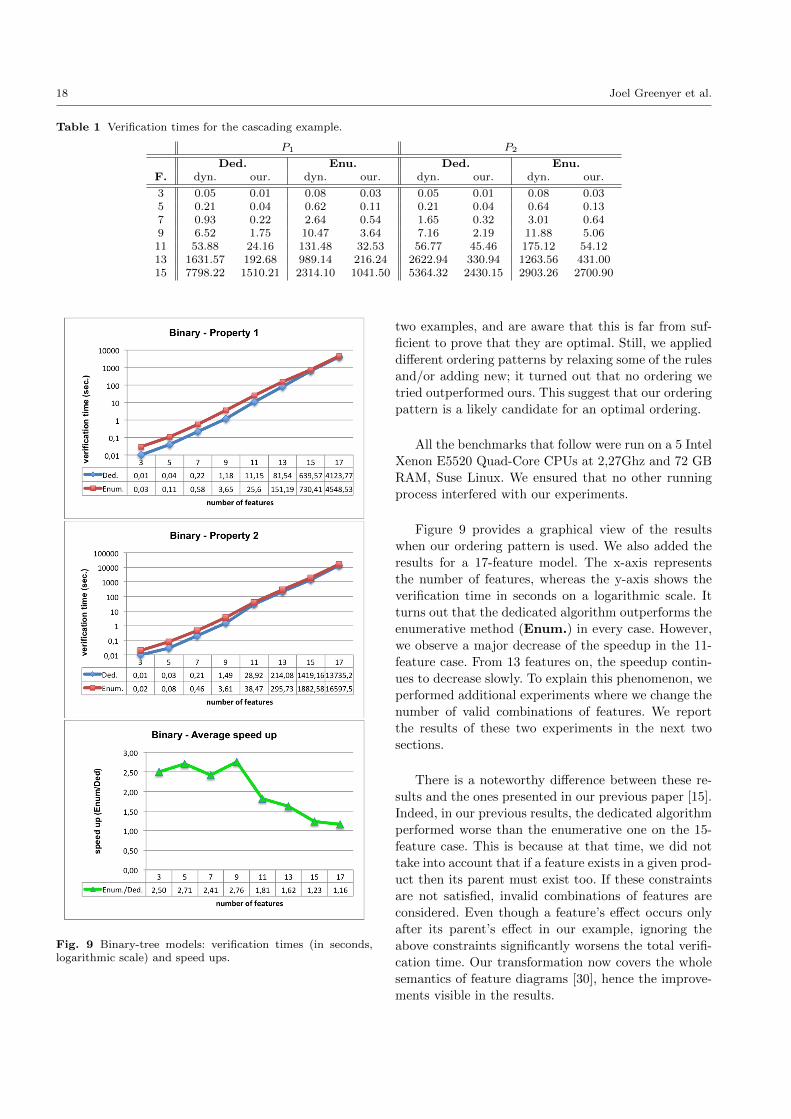
18 Joel Greenyer et al.
Table 1 Verification times for the cascading example.
P1 P2
Ded. Enu. Ded. Enu.F. dyn. our. dyn. our. dyn. our. dyn. our.
3 0.05 0.01 0.08 0.03 0.05 0.01 0.08 0.035 0.21 0.04 0.62 0.11 0.21 0.04 0.64 0.137 0.93 0.22 2.64 0.54 1.65 0.32 3.01 0.649 6.52 1.75 10.47 3.64 7.16 2.19 11.88 5.0611 53.88 24.16 131.48 32.53 56.77 45.46 175.12 54.1213 1631.57 192.68 989.14 216.24 2622.94 330.94 1263.56 431.0015 7798.22 1510.21 2314.10 1041.50 5364.32 2430.15 2903.26 2700.90
Fig. 9 Binary-tree models: verification times (in seconds,logarithmic scale) and speed ups.
two examples, and are aware that this is far from suf-
ficient to prove that they are optimal. Still, we applied
different ordering patterns by relaxing some of the rules
and/or adding new; it turned out that no ordering we
tried outperformed ours. This suggest that our ordering
pattern is a likely candidate for an optimal ordering.
All the benchmarks that follow were run on a 5 Intel
Xenon E5520 Quad-Core CPUs at 2,27Ghz and 72 GB
RAM, Suse Linux. We ensured that no other running
process interfered with our experiments.
Figure 9 provides a graphical view of the results
when our ordering pattern is used. We also added the
results for a 17-feature model. The x-axis represents
the number of features, whereas the y-axis shows the
verification time in seconds on a logarithmic scale. It
turns out that the dedicated algorithm outperforms the
enumerative method (Enum.) in every case. However,
we observe a major decrease of the speedup in the 11-
feature case. From 13 features on, the speedup contin-
ues to decrease slowly. To explain this phenomenon, we
performed additional experiments where we change the
number of valid combinations of features. We report
the results of these two experiments in the next two
sections.
There is a noteworthy difference between these re-
sults and the ones presented in our previous paper [15].
Indeed, in our previous results, the dedicated algorithm
performed worse than the enumerative one on the 15-
feature case. This is because at that time, we did not
take into account that if a feature exists in a given prod-
uct then its parent must exist too. If these constraints
are not satisfied, invalid combinations of features are
considered. Even though a feature’s effect occurs only
after its parent’s effect in our example, ignoring the
above constraints significantly worsens the total verifi-
cation time. Our transformation now covers the whole
semantics of feature diagrams [30], hence the improve-
ments visible in the results.
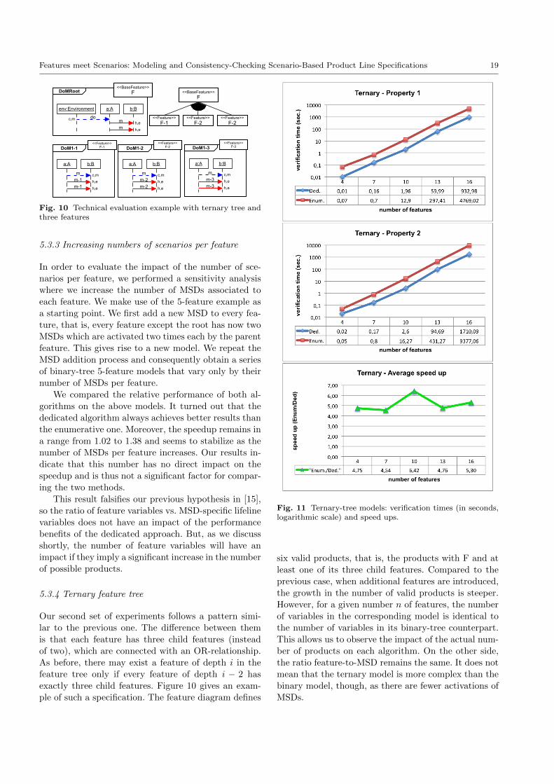
Features meet Scenarios: Modeling and Consistency-Checking Scenario-Based Product Line Specifications 19
do
env:Environment a:A b:B
DoMRoot
m
m
m
a:A b:B
DoM1-1
m-1
m-1
m
a:A b:B
DoM1-2
m-2
m-2
<<Feature>>
F-2<<Feature>>
F-1
<<BaseFeature>>
F
<<BaseFeature>>
F
<<Feature>>F-1
<<Feature>>F-2
h,e
h,e
c,m
h,e
h,e
c,m
c,mh,e
h,e
m
a:A b:B
DoM1-3
m-3
m-3
<<Feature>>F-3
h,e
h,e
c,m
<<Feature>>
F-2
Fig. 10 Technical evaluation example with ternary tree andthree features
5.3.3 Increasing numbers of scenarios per feature
In order to evaluate the impact of the number of sce-
narios per feature, we performed a sensitivity analysis
where we increase the number of MSDs associated to
each feature. We make use of the 5-feature example as
a starting point. We first add a new MSD to every fea-
ture, that is, every feature except the root has now two
MSDs which are activated two times each by the parent
feature. This gives rise to a new model. We repeat the
MSD addition process and consequently obtain a series
of binary-tree 5-feature models that vary only by their
number of MSDs per feature.
We compared the relative performance of both al-
gorithms on the above models. It turned out that the
dedicated algorithm always achieves better results than
the enumerative one. Moreover, the speedup remains in
a range from 1.02 to 1.38 and seems to stabilize as the
number of MSDs per feature increases. Our results in-
dicate that this number has no direct impact on the
speedup and is thus not a significant factor for compar-
ing the two methods.
This result falsifies our previous hypothesis in [15],
so the ratio of feature variables vs. MSD-specific lifeline
variables does not have an impact of the performance
benefits of the dedicated approach. But, as we discuss
shortly, the number of feature variables will have an
impact if they imply a significant increase in the number
of possible products.
5.3.4 Ternary feature tree
Our second set of experiments follows a pattern simi-
lar to the previous one. The difference between them
is that each feature has three child features (instead
of two), which are connected with an OR-relationship.
As before, there may exist a feature of depth i in the
feature tree only if every feature of depth i − 2 has
exactly three child features. Figure 10 gives an exam-
ple of such a specification. The feature diagram defines
Fig. 11 Ternary-tree models: verification times (in seconds,logarithmic scale) and speed ups.
six valid products, that is, the products with F and at
least one of its three child features. Compared to the
previous case, when additional features are introduced,
the growth in the number of valid products is steeper.
However, for a given number n of features, the number
of variables in the corresponding model is identical to
the number of variables in its binary-tree counterpart.
This allows us to observe the impact of the actual num-
ber of products on each algorithm. On the other side,
the ratio feature-to-MSD remains the same. It does not
mean that the ternary model is more complex than the
binary model, though, as there are fewer activations of
MSDs.
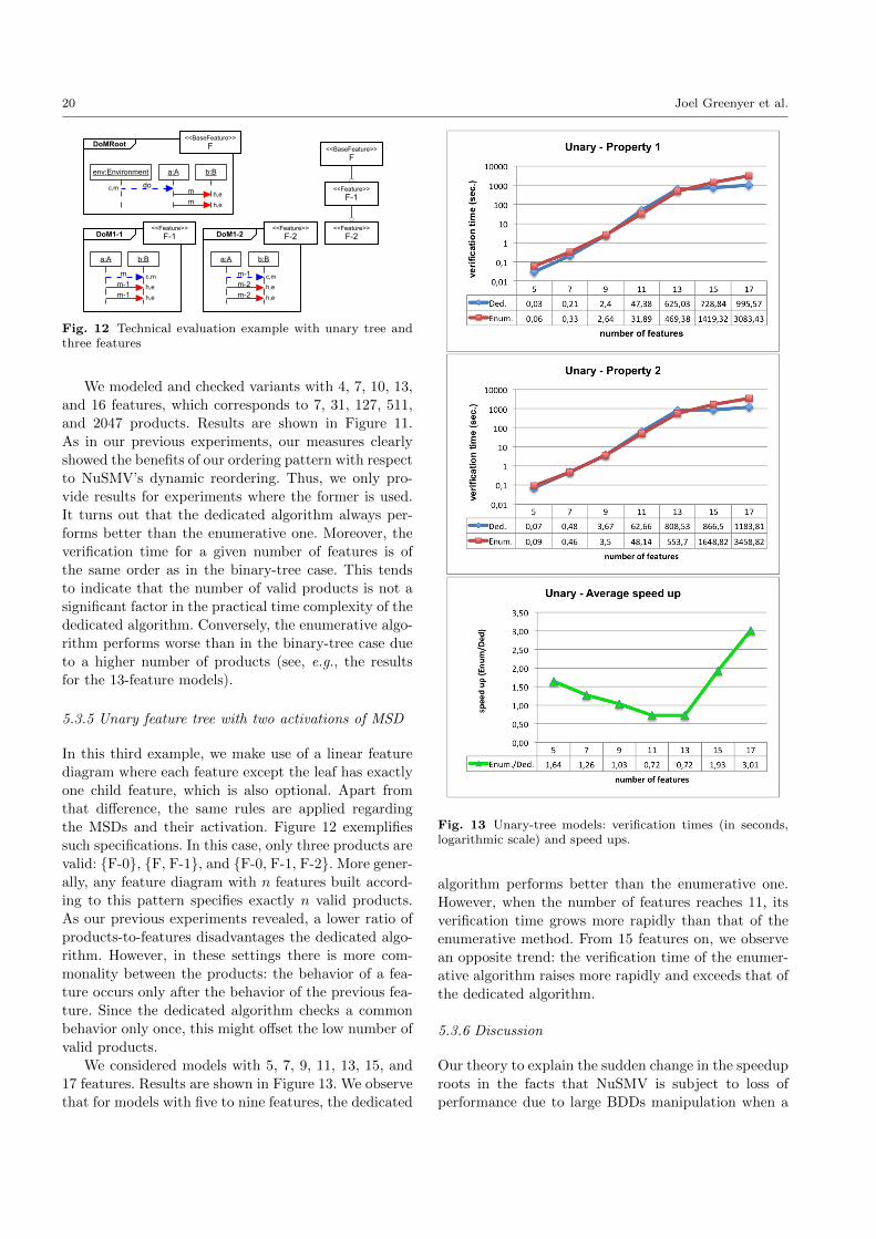
20 Joel Greenyer et al.
do
env:Environment a:A b:B
DoMRoot
m
m
m
a:A b:B
DoM1-1
m-1
m-1
m-1
a:A b:B
DoM1-2
m-2
m-2
<<Feature>>
F-2
<<Feature>>
F-1
<<BaseFeature>>
F
<<BaseFeature>>
F
<<Feature>>
F-1<<Feature>>
F-2
h,e
h,e
c,m
h,e
h,e
c,m
c,mh,e
h,e
Fig. 12 Technical evaluation example with unary tree andthree features
We modeled and checked variants with 4, 7, 10, 13,
and 16 features, which corresponds to 7, 31, 127, 511,
and 2047 products. Results are shown in Figure 11.
As in our previous experiments, our measures clearly
showed the benefits of our ordering pattern with respect
to NuSMV’s dynamic reordering. Thus, we only pro-
vide results for experiments where the former is used.
It turns out that the dedicated algorithm always per-
forms better than the enumerative one. Moreover, the
verification time for a given number of features is of
the same order as in the binary-tree case. This tends
to indicate that the number of valid products is not a
significant factor in the practical time complexity of the
dedicated algorithm. Conversely, the enumerative algo-
rithm performs worse than in the binary-tree case due
to a higher number of products (see, e.g., the results
for the 13-feature models).
5.3.5 Unary feature tree with two activations of MSD
In this third example, we make use of a linear feature
diagram where each feature except the leaf has exactly
one child feature, which is also optional. Apart from
that difference, the same rules are applied regarding
the MSDs and their activation. Figure 12 exemplifies
such specifications. In this case, only three products are
valid: {F-0}, {F, F-1}, and {F-0, F-1, F-2}. More gener-
ally, any feature diagram with n features built accord-
ing to this pattern specifies exactly n valid products.
As our previous experiments revealed, a lower ratio of
products-to-features disadvantages the dedicated algo-
rithm. However, in these settings there is more com-
monality between the products: the behavior of a fea-
ture occurs only after the behavior of the previous fea-
ture. Since the dedicated algorithm checks a common
behavior only once, this might offset the low number of
valid products.
We considered models with 5, 7, 9, 11, 13, 15, and
17 features. Results are shown in Figure 13. We observe
that for models with five to nine features, the dedicated
Fig. 13 Unary-tree models: verification times (in seconds,logarithmic scale) and speed ups.
algorithm performs better than the enumerative one.
However, when the number of features reaches 11, its
verification time grows more rapidly than that of the
enumerative method. From 15 features on, we observe
an opposite trend: the verification time of the enumer-
ative algorithm raises more rapidly and exceeds that of
the dedicated algorithm.
5.3.6 Discussion
Our theory to explain the sudden change in the speedup
roots in the facts that NuSMV is subject to loss of
performance due to large BDDs manipulation when a
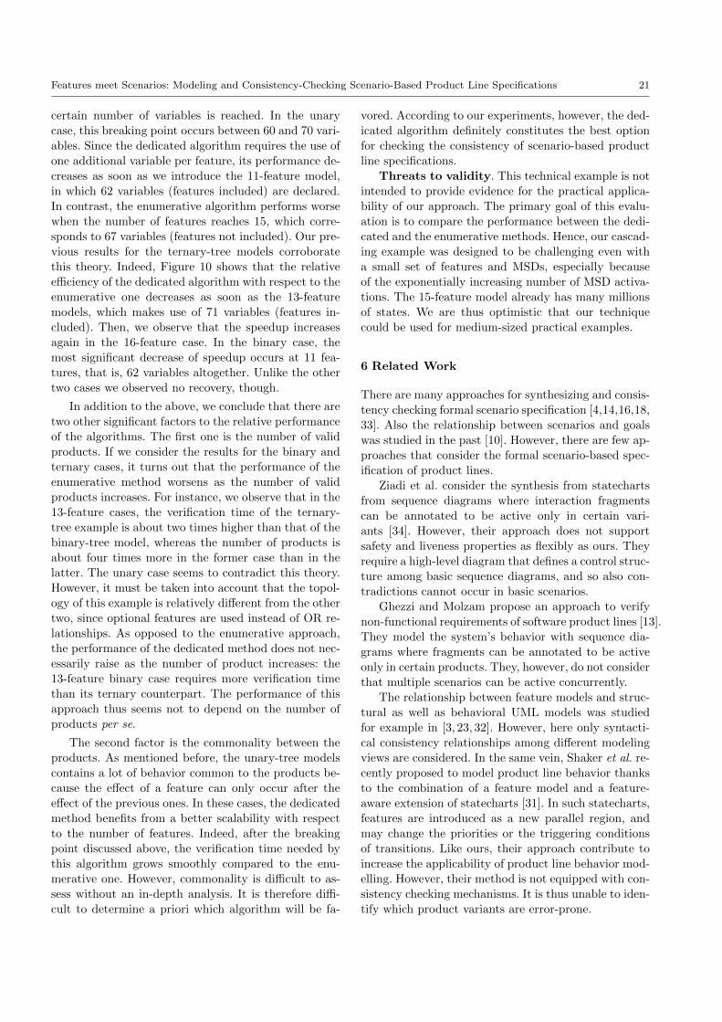
Features meet Scenarios: Modeling and Consistency-Checking Scenario-Based Product Line Specifications 21
certain number of variables is reached. In the unary
case, this breaking point occurs between 60 and 70 vari-
ables. Since the dedicated algorithm requires the use of
one additional variable per feature, its performance de-
creases as soon as we introduce the 11-feature model,
in which 62 variables (features included) are declared.
In contrast, the enumerative algorithm performs worse
when the number of features reaches 15, which corre-
sponds to 67 variables (features not included). Our pre-
vious results for the ternary-tree models corroborate
this theory. Indeed, Figure 10 shows that the relative
efficiency of the dedicated algorithm with respect to the
enumerative one decreases as soon as the 13-feature
models, which makes use of 71 variables (features in-
cluded). Then, we observe that the speedup increases
again in the 16-feature case. In the binary case, the
most significant decrease of speedup occurs at 11 fea-
tures, that is, 62 variables altogether. Unlike the other
two cases we observed no recovery, though.
In addition to the above, we conclude that there are
two other significant factors to the relative performance
of the algorithms. The first one is the number of valid
products. If we consider the results for the binary and
ternary cases, it turns out that the performance of the
enumerative method worsens as the number of valid
products increases. For instance, we observe that in the
13-feature cases, the verification time of the ternary-
tree example is about two times higher than that of the
binary-tree model, whereas the number of products is
about four times more in the former case than in the
latter. The unary case seems to contradict this theory.
However, it must be taken into account that the topol-
ogy of this example is relatively different from the other
two, since optional features are used instead of OR re-
lationships. As opposed to the enumerative approach,
the performance of the dedicated method does not nec-
essarily raise as the number of product increases: the
13-feature binary case requires more verification time
than its ternary counterpart. The performance of this
approach thus seems not to depend on the number of
products per se.
The second factor is the commonality between the
products. As mentioned before, the unary-tree models
contains a lot of behavior common to the products be-
cause the effect of a feature can only occur after the
effect of the previous ones. In these cases, the dedicated
method benefits from a better scalability with respect
to the number of features. Indeed, after the breaking
point discussed above, the verification time needed by
this algorithm grows smoothly compared to the enu-
merative one. However, commonality is difficult to as-
sess without an in-depth analysis. It is therefore diffi-
cult to determine a priori which algorithm will be fa-
vored. According to our experiments, however, the ded-
icated algorithm definitely constitutes the best option
for checking the consistency of scenario-based product
line specifications.
Threats to validity. This technical example is not
intended to provide evidence for the practical applica-
bility of our approach. The primary goal of this evalu-
ation is to compare the performance between the dedi-
cated and the enumerative methods. Hence, our cascad-
ing example was designed to be challenging even with
a small set of features and MSDs, especially because
of the exponentially increasing number of MSD activa-
tions. The 15-feature model already has many millions
of states. We are thus optimistic that our technique
could be used for medium-sized practical examples.
6 Related Work
There are many approaches for synthesizing and consis-
tency checking formal scenario specification [4,14,16,18,
33]. Also the relationship between scenarios and goals
was studied in the past [10]. However, there are few ap-
proaches that consider the formal scenario-based spec-
ification of product lines.
Ziadi et al. consider the synthesis from statecharts
from sequence diagrams where interaction fragments
can be annotated to be active only in certain vari-
ants [34]. However, their approach does not support
safety and liveness properties as flexibly as ours. They
require a high-level diagram that defines a control struc-
ture among basic sequence diagrams, and so also con-
tradictions cannot occur in basic scenarios.
Ghezzi and Molzam propose an approach to verify
non-functional requirements of software product lines [13].
They model the system’s behavior with sequence dia-
grams where fragments can be annotated to be active
only in certain products. They, however, do not consider
that multiple scenarios can be active concurrently.
The relationship between feature models and struc-
tural as well as behavioral UML models was studied
for example in [3, 23, 32]. However, here only syntacti-
cal consistency relationships among different modeling
views are considered. In the same vein, Shaker et al. re-
cently proposed to model product line behavior thanks
to the combination of a feature model and a feature-
aware extension of statecharts [31]. In such statecharts,
features are introduced as a new parallel region, and
may change the priorities or the triggering conditions
of transitions. Like ours, their approach contribute to
increase the applicability of product line behavior mod-
elling. However, their method is not equipped with con-
sistency checking mechanisms. It is thus unable to iden-
tify which product variants are error-prone.
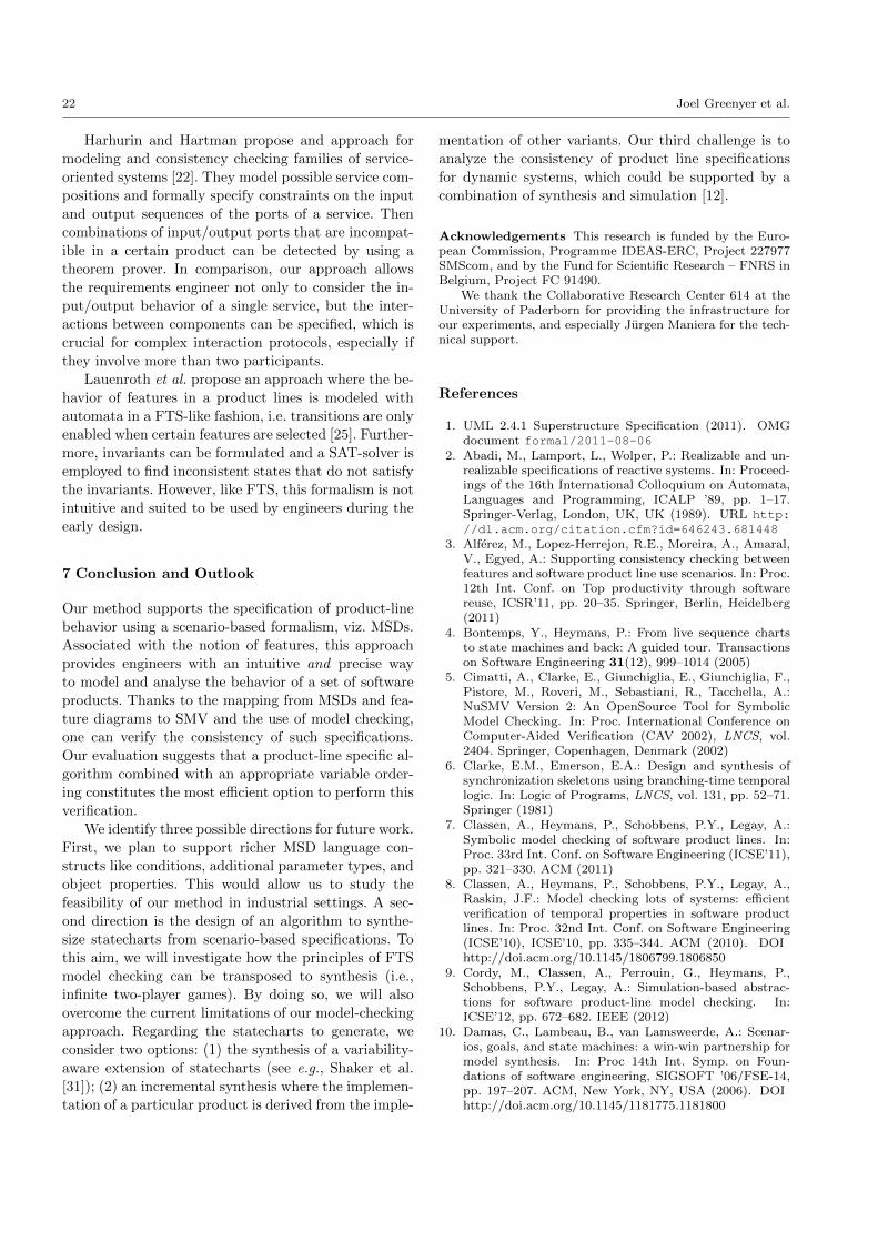
22 Joel Greenyer et al.
Harhurin and Hartman propose and approach for
modeling and consistency checking families of service-
oriented systems [22]. They model possible service com-
positions and formally specify constraints on the input
and output sequences of the ports of a service. Then
combinations of input/output ports that are incompat-
ible in a certain product can be detected by using a
theorem prover. In comparison, our approach allows
the requirements engineer not only to consider the in-
put/output behavior of a single service, but the inter-
actions between components can be specified, which is
crucial for complex interaction protocols, especially if
they involve more than two participants.
Lauenroth et al. propose an approach where the be-
havior of features in a product lines is modeled with
automata in a FTS-like fashion, i.e. transitions are only
enabled when certain features are selected [25]. Further-
more, invariants can be formulated and a SAT-solver is
employed to find inconsistent states that do not satisfy
the invariants. However, like FTS, this formalism is not
intuitive and suited to be used by engineers during the
early design.
7 Conclusion and Outlook
Our method supports the specification of product-line
behavior using a scenario-based formalism, viz. MSDs.
Associated with the notion of features, this approach
provides engineers with an intuitive and precise way
to model and analyse the behavior of a set of software
products. Thanks to the mapping from MSDs and fea-
ture diagrams to SMV and the use of model checking,
one can verify the consistency of such specifications.
Our evaluation suggests that a product-line specific al-
gorithm combined with an appropriate variable order-
ing constitutes the most efficient option to perform this
verification.
We identify three possible directions for future work.
First, we plan to support richer MSD language con-
structs like conditions, additional parameter types, and
object properties. This would allow us to study the
feasibility of our method in industrial settings. A sec-
ond direction is the design of an algorithm to synthe-
size statecharts from scenario-based specifications. To
this aim, we will investigate how the principles of FTS
model checking can be transposed to synthesis (i.e.,
infinite two-player games). By doing so, we will also
overcome the current limitations of our model-checking
approach. Regarding the statecharts to generate, we
consider two options: (1) the synthesis of a variability-
aware extension of statecharts (see e.g., Shaker et al.
[31]); (2) an incremental synthesis where the implemen-
tation of a particular product is derived from the imple-
mentation of other variants. Our third challenge is to
analyze the consistency of product line specifications
for dynamic systems, which could be supported by a
combination of synthesis and simulation [12].
Acknowledgements This research is funded by the Euro-pean Commission, Programme IDEAS-ERC, Project 227977SMScom, and by the Fund for Scientific Research – FNRS inBelgium, Project FC 91490.
We thank the Collaborative Research Center 614 at theUniversity of Paderborn for providing the infrastructure forour experiments, and especially Jurgen Maniera for the tech-nical support.
References
1. UML 2.4.1 Superstructure Specification (2011). OMGdocument formal/2011-08-06
2. Abadi, M., Lamport, L., Wolper, P.: Realizable and un-realizable specifications of reactive systems. In: Proceed-ings of the 16th International Colloquium on Automata,Languages and Programming, ICALP ’89, pp. 1–17.Springer-Verlag, London, UK, UK (1989). URL http://dl.acm.org/citation.cfm?id=646243.681448
3. Alferez, M., Lopez-Herrejon, R.E., Moreira, A., Amaral,V., Egyed, A.: Supporting consistency checking betweenfeatures and software product line use scenarios. In: Proc.12th Int. Conf. on Top productivity through softwarereuse, ICSR’11, pp. 20–35. Springer, Berlin, Heidelberg(2011)
4. Bontemps, Y., Heymans, P.: From live sequence chartsto state machines and back: A guided tour. Transactionson Software Engineering 31(12), 999–1014 (2005)
5. Cimatti, A., Clarke, E., Giunchiglia, E., Giunchiglia, F.,Pistore, M., Roveri, M., Sebastiani, R., Tacchella, A.:NuSMV Version 2: An OpenSource Tool for SymbolicModel Checking. In: Proc. International Conference onComputer-Aided Verification (CAV 2002), LNCS, vol.2404. Springer, Copenhagen, Denmark (2002)
6. Clarke, E.M., Emerson, E.A.: Design and synthesis ofsynchronization skeletons using branching-time temporallogic. In: Logic of Programs, LNCS, vol. 131, pp. 52–71.Springer (1981)
7. Classen, A., Heymans, P., Schobbens, P.Y., Legay, A.:Symbolic model checking of software product lines. In:Proc. 33rd Int. Conf. on Software Engineering (ICSE’11),pp. 321–330. ACM (2011)
8. Classen, A., Heymans, P., Schobbens, P.Y., Legay, A.,Raskin, J.F.: Model checking lots of systems: efficientverification of temporal properties in software productlines. In: Proc. 32nd Int. Conf. on Software Engineering(ICSE’10), ICSE’10, pp. 335–344. ACM (2010). DOIhttp://doi.acm.org/10.1145/1806799.1806850
9. Cordy, M., Classen, A., Perrouin, G., Heymans, P.,Schobbens, P.Y., Legay, A.: Simulation-based abstrac-tions for software product-line model checking. In:ICSE’12, pp. 672–682. IEEE (2012)
10. Damas, C., Lambeau, B., van Lamsweerde, A.: Scenar-ios, goals, and state machines: a win-win partnership formodel synthesis. In: Proc 14th Int. Symp. on Foun-dations of software engineering, SIGSOFT ’06/FSE-14,pp. 197–207. ACM, New York, NY, USA (2006). DOIhttp://doi.acm.org/10.1145/1181775.1181800
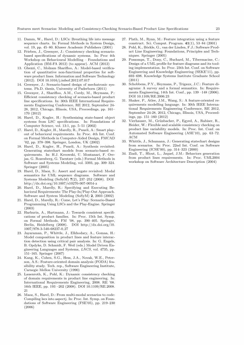
Features meet Scenarios: Modeling and Consistency-Checking Scenario-Based Product Line Specifications 23
11. Damm, W., Harel, D.: LSCs: Breathing life into messagesequence charts. In: Formal Methods in System Design,vol. 19, pp. 45–80. Kluwer Academic Publishers (2001)
12. Frieben, J., Greenyer, J.: Consistency checking scenario-based specifications of dynamic systems. In: Proc 4thWorkshop on Behavioural Modelling – Foundations andApplication (BM-FA 2012) (to appear). ACM (2012)
13. Ghezzi, C., Molzam Sharifloo, A.: Model-based verifica-tion of quantitative non-functional properties for soft-ware product lines. Information and Software Technology(2012). DOI 10.1016/j.infsof.2012.07.017
14. Greenyer, J.: Scenario-based design of mechatronic sys-tems. Ph.D. thesis, University of Paderborn (2011)
15. Greenyer, J., Sharifloo, A.M., Cordy, M., Heymans, P.:Efficient consistency checking of scenario-based productline specifications. In: 30th IEEE International Require-ments Engineering Conference, RE 2012, September 24-28, 2012, Chicago, Illinois, USA, Proceedings, pp. 161–170 (2012)
16. Harel, D., Kugler, H.: Synthesizing state-based objectsystems from LSC specifications. In: Foundations ofComputer Science, vol. 13:1, pp. 5–51 (2002)
17. Harel, D., Kugler, H., Marelly, R., Pnueli, A.: Smart play-out of behavioral requirements. In: Proc. 4th Int. Conf.on Formal Methods in Computer-Aided Design, FMCAD’02, pp. 378–398. Springer, London, UK (2002)
18. Harel, D., Kugler, H., Pnueli, A.: Synthesis revisited:Generating statechart models from scenario-based re-quirements. In: H.J. Kreowski, U. Montanari, F. Ore-jas, G. Rozenberg, G. Taentzer (eds.) Formal Methods inSoftware and Systems Modeling, vol. 3393, pp. 309–324.Springer (2005)
19. Harel, D., Maoz, S.: Assert and negate revisited: Modalsemantics for UML sequence diagrams. Software andSystems Modeling (SoSyM) 7(2), 237–252 (2008). DOIhttp://dx.doi.org/10.1007/s10270-007-0054-z
20. Harel, D., Marelly, R.: Specifying and Executing Be-havioral Requirements: The Play-In/Play-Out Approach.Software and System Modeling (SoSyM) 2, 2003 (2002)
21. Harel, D., Marelly, R.: Come, Let’s Play: Scenario-BasedProgramming Using LSCs and the Play-Engine. Springer(2003)
22. Harhurin, A., Hartmann, J.: Towards consistent specifi-cations of product families. In: Proc. 15th Int. Symp.on Formal Methods, FM ’08, pp. 390–405. Springer,Berlin, Heidelberg (2008). DOI http://dx.doi.org/10.1007/978-3-540-68237-0 27
23. Jayaraman, P., Whittle, J., Elkhodary, A., Gomaa, H.:Model composition in product lines and feature interac-tion detection using critical pair analysis. In: G. Engels,B. Opdyke, D. Schmidt, F. Weil (eds.) Model Driven En-gineering Languages and Systems, LNCS, vol. 4735, pp.151–165. Springer (2007)
24. Kang, K., Cohen, S.G., Hess, J.A., Novak, W.E., Peter-son, A.S.: Feature-oriented domain analysis (FODA) fea-sibility study. Tech. rep., Software Engineering Institute,Carnegie Mellon University (1990)
25. Lauenroth, K., Pohl, K.: Dynamic consistency checkingof domain requirements in product line engineering. In:International Requirements Engineering, 2008. RE ’08.16th IEEE, pp. 193 –202 (2008). DOI 10.1109/RE.2008.21
26. Maoz, S., Harel, D.: From multi-modal scenarios to code:Compiling lscs into aspectj. In: Proc. Int. Symp. on Foun-dations of Software Engineering (FSE’05), pp. 219–230(2006)
27. Plath, M., Ryan, M.: Feature integration using a featureconstruct. Sci. Comput. Program. 41(1), 53–84 (2001)
28. Pohl, K., Bockle, G., van der Linden, F.J.: Software Prod-uct Line Engineering: Foundations, Principles and Tech-niques. Springer (2005)
29. Possomps, T., Dony, C., Huchard, M., Tibermacine, C.:Design of a UML profile for feature diagrams and its tool-ing implementation. In: Proc. 23th Int. Conf. on SoftwareEngineering and Knowledge Engineering (SEKE’11), pp.693–698. Knowledge Systems Institute Graduate School(2011)
30. Schobbens, P.Y., Heymans, P., Trigaux, J.C.: Feature di-agrams: A survey and a formal semantics. In: Require-ments Engineering, 14th Int. Conf., pp. 139 –148 (2006).DOI 10.1109/RE.2006.23
31. Shaker, P., Atlee, J.M., Wang, S.: A feature-oriented re-quirements modelling language. In: 30th IEEE Interna-tional Requirements Engineering Conference, RE 2012,September 24-28, 2012, Chicago, Illinois, USA, Proceed-ings, pp. 151–160 (2012)
32. Vierhauser, M., Grunbacher, P., Egyed, A., Rabiser, R.,Heider, W.: Flexible and scalable consistency checking onproduct line variability models. In: Proc. Int. Conf. onAutomated Software Engineering (ASE’10), pp. 63–72.ACM
33. Whittle, J., Schumann, J.: Generating statechart designsfrom scenarios. In: Proc. 22nd Int. Conf. on SoftwareEngineering (ICSE’00), pp. 314–323 (2000)
34. Ziadi, T., Hlout, L., Jzquel, J.M.: Behaviors generationfrom product lines requirements. In: Proc. UML2004workshop on Software Architecture Description (2004)