Embed Size (px)
Citation preview
da
tamodel 777T
productguide
features• 181 mton (200 ton) capacity
• 698 mton-m (5,050 kips) Maximum Load Moment
• 82,3 m (270') Heavy-Lift Boom
• 90,8 m (298') Long-Reach Boom
• 91,4 m (300') Fixed Jibon Heavy-Lift Boom
• 96,9 m (318') Fixed Jibon Long-Reach Boom
• 106,7 m (350') Luffing Jibon Heavy-Lift Boom
• 125,0 m (410') Fixed Jib on Luffing Jibon Heavy-Lift Boom
• 195 kW (260 HP) engine upperworks
• 373 kW (500 HP) engine carrier
• EPIC5 controls
• 135 m/min (442 fpm) line speed standard
• 177 m/min (581 fpm) line speed optional
• 131 kN (29,500 lb) line pull standard
• Hydraulic-cylinder Boom Hoist for maximum performance with minimum maintenance
• Fast, efficient self-assembly
• 10x6 Carrier travels with upperworks in place.96,6 kph (60 mph) travel speed.
• Manitowoc CraneCARE5
contentsSpecifications 3
Outline Dimensions 7
Transport / Assembly 13
Performance Data 16Boom Combinations 24Main BoomRange / Load Charts 27Long ReachRange / Load Charts 31Fixed Jib Range / Load Charts 33Luffing JibRange / Load Charts 39Luffing Jib on Luffing JibRange / Load Charts 43
CraneCARESM 47
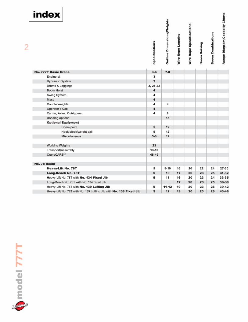
No. 777T Basic Crane 3-6 7-8
Engine(s) 3
Hydraulic System 3
Drums & Laggings 3, 21-22
Boom Hoist 4
Swing System 4
Mast 4
Counterweights 4 9
Operator’s Cab 4
Carrier, Axles, Outriggers 4 9
Roading options 13
Optional Equipment
Boom point 5 12
Hook block/weight ball 5 12
Miscellaneous 5-6 12
Working Weights 23
Transport/Assembly 13-15
CraneCARESM 48-49
No. 78 Boom
Heavy-Lift No. 78T 5 9-10 16 20 22 24 27-30
Long-Reach No. 78T 5 10 17 20 23 25 31-32
Heavy-Lift No. 78T with No. 134 Fixed Jib 5 11 16 20 23 24 33-35
Long-Reach No. 78T with No. 134 Fixed Jib 17 20 23 25 36-38
Heavy-Lift No. 78T with No. 139 Luffing Jib 5 11-12 19 20 23 26 39-42
Heavy-Lift No. 78T with No, 139 Luffing Jib with No. 138 Fixed Jib 5 12 19 20 23 26 43-46
2
indexm
od
el
77
7T
Sp
ec
ific
ati
on
s
Ou
tlin
e D
ime
ns
ion
s/W
eig
hts
Wir
e R
op
e L
en
gth
s
Wir
e R
op
e S
pe
cif
ica
tio
ns
Bo
om
Ra
isin
g
Bo
om
Co
mb
ina
tio
ns
Ra
ng
e D
iag
ram
/Ca
pa
cit
y C
ha
rts
Upperworks
Engine
Cummins Model 6CTA 8.3 – C260 diesel, 6 cylinder,195 kW (260 BHP) @ 2200 governed RPM.
Optional: Caterpillar Model C-9 diesel, 6 cylinder,253 kW (340 BHP) @ 2100 governed RPM.
Includes engine block heater (120 V), ether starting aid,manually operated disconnect clutch for cold weatherstarting, high silencing muffler, hydraulic oil cooler,radiator and fan.
Multiple hydraulic pump drive transmission providesindependent power for all machine functions.
Two 12 volt maintenance-free, Group 8D batteries, 1400CCA at -18°C (0° F), 24 volt starting and 120 ampalternator.
One 469 l (124 gal) capacity diesel fuel tank, mounted onrear of upperworks, with level indicator in operator’s cab.
Controls
Modulating electronic-over-hydraulic controls provideinfinite speed response directly proportional to controllever movement. Controls include Manitowoc's exclusiveEPIC® Electronically Processed Independent Control systemproviding microprocessor driven control logic, pumpcontrol, on-board diagnostics, and service information.
Block-up limit control is standard for hoist and auxiliary lines.
Integrated Load Moment Indicator system (LMI) isstandard for main boom. “Function cut-out” or “warningonly” operation is selected via a keyed switch on the LMIconsole. Includes travel and swing alarms.
Optional: Upper boom point assembly with LMI.
Optional: Anemometer (wind indicator).
Hydraulic System
Four high-pressure piston pumps are driven through amulti-hydraulic pump transmission. These six pumpsprovide independent “closed loop” hydraulic power forfront drum, rear drum, boom hoist system, swing system,and both left and right crawler operation.
System kg/cm2 (psi) lpm (gpm)Front Drum 422 (6,000) 300 (79)Rear Drum 422 (6,000) 300 (79)Boom Hoist 422 (6,000) 300 (79)Swing System 386 (5,500) 225 (59)Auxiliary Pump* 422 (6,000) 390 (102)
*Optional pump powers auxiliary drum on liftcrane.
Hydraulic reservoir capacity is 469 l (124 gal) and isequipped with breather, dipstick, clean out access, andinternal diffuser.
Each function is equipped with relief valves to protect thehydraulic circuit from overload or shock.
Replaceable, spin on ten micron (absolute) full flow linefilter is furnished in the hydraulic circuit. All oil is filteredprior to return to the hydraulic reservoir.
Hydraulic system also includes pump transmissiondisconnect clutch & hydraulic oil cooler.
Drums
Two equal width winches 770 mm (30-1/8") wide and495 mm (19-1/2") diameter are driven by independentvariable displacement axial piston hydraulic motorsthrough planetary reduction mounted on separate frontand rear shafts with anti-friction bearings. Drums aregrooved for 25,4 mm (1") rope.
Powered hoisting/lowering operation is standard withautomatic (spring applied, hydraulically released) multi-disc brakes, and drum rotation indicators.
Optional: Free-fall operation for front and/or reardrum(s). External contracting band brake mounted ondrum manually applied by foot pedal with locking latchin operator’s cab. Operator may select free-fall orpowered lowering mode using a selector switch.
Optional: High line speed drum 207m/min (581fpm) can be ordered in place of standard front or reardrum.
Optional: Auxiliary (third) hydraulic powered drumrated at 89,0 kN (20,000 lb) line pull mounted in boombutt. Includes third drum control system.
Optional: Auxiliary drum preparation includeselectric wiring, controls, hydraulic pump and plumbing.
Optional: Bolt-on liftcrane/clamshell laggings.
Optional: Wire rope for various applications.
3
specifications
mo
de
l7
77
T
Mast
Moving mast is 7,9 m (26') long and connects the boomhoist cylinders to the boom-support pendants.
Spring cushioned boom stop and automatic boom stopstandard.
Boom Hoist
Independent boom hoist is provided by two double-actinghydraulic cylinders connected to the mast. Boom hoistprovides full range of boom angles from horizontal to 88degrees, with or without load.
Boom hoist speed: raise 82,3 m (270') full main boomfrom 0˚- 82˚ in 1 minute, 40 seconds.
Swing System
High strength fabricated steel rotating bed is mounted on2,15 m (84-1/2") diameter turntable single-row ballbearing.
Independent swing powered by a fixed displacementhydraulic motor coupled to a planetary gearbox withinternal brake. 360˚ positive swing lock.
Swing system maximum speed: 2.7 rpm.
Counterweight
Includes connecting pins, brackets, and stops.
Operator’s Cab
Fully enclosed and insulated steel module located at theleft front corner of rotating bed. Module is equippedwith sliding door, large safety glass windows on all sidesand roof. Signal horn, cab space heater, front and roofwindshield wipers, dome light, sun visor and shade, fireextinguisher and air circulating fan are standard.
Optional: Air conditioner.
Optional: Nylon protective window covers.
Truck Chassis
Carrier
10 x 6 carrier has an overall length of 12,2 m (40' 0") andis 3,35 m (11' 0") wide with the rear outrigger assemblyremoved. The carrier is powered by a Detroit Diesel Series60 diesel engine rated at 373 kW (500 HP) at 2100 RPMand an Allison HD4560 automatic transmission (6 speedsforward, 1 reverse) with a four speed auxiliarytransmission. A Jacob’s “Jake Brake” engine retarder isincluded as standard on the engine. Carrier fuel tank of100 gallon capacity is provided as standard.
Axles
Axles 1 and 2 are steerable, single wheel type, 2 972 mm(117") track and mounted on a spring-over-walking beamsuspension. Axles 3, 4, and 5 are planetary, dual wheeltype, 2 540 mm (100") track and mounted on a walkingbeam suspension.
Outriggers
The rear outriggers are bypassing tunnel out-and-downtype, FACTTM connected to the rear of the carrier, andhydraulically extended and retracted. The front outriggersare radial type and are FACT connected to the mid-section of the carrier. The front outriggers are hinged toswing radially and can be either removed or swungforward hydraulically to provide and 3,35 m (11' 0")travel width. All outriggers are equipped with hydraulicjacks with check valves and 91cm (36") diametercomposite outrigger pads. Front hydraulic jack assembly ismounted on front of carrier to support carrier engine anddriver’s cab weight during crane operation, and isequipped with 64cm (24") diameter. composite pad.Outrigger controls are located on each side of carrier andin carrier cab as standard equipment.
Chassis Operator’s Cab
The large one-man cab is an insulated module withadequate ventilation to provide excellent driver comfortand visibility. Left side window (in door) rolls down.Right side window slides open. Cab accessories includenormal vehicle accessories, instrumentation, and an air-ride seat.
4
specificationsm
od
el
77
7T
UNIT WEIGHT TOTAL WEIGHTQTY. ITEM kg lb kg lb
Upper1 Tray 4 717 10,400 4 717 10,4005 Upper Box 7 699 16,975 38 495 84,875
UPPER TOTAL 47 628 95,400
Front Bumper1 Adapter 3 649 8,045 3 649 8,0451 Front Box 7 699 16,975 7 699 16,975
FRONT BUMPER TOTAL 11 340 25,000
COMBINED TOTAL 54 613 120,400
Attachments
No. 78T Heavy-Lift Main Boom
The liftcrane is equipped with a 18,3 m (60') No. 78Tbasic heavy-lift angle chord boom consisting of a 6,9 m(22' 6") No. 78T two-piece butt, 5,3 m (17' 6") No. 78Tbasic insert and 6,1 m (20') No. 78T quick reave top withsix 76,2 cm (30") diameter roller bearing sheaves on oneshaft. Includes rope guides, boom angle indicator, and13,6 mton (15 ton) swivel hook and weight ball. The No.78T boom utilizes steel suspension straps andManitowoc’s patented, exclusive FACTTM connectionsystem. The FACT connection system consists of twovertical pins, two horizontal connection pins andalignment pads for each boom connection location.
Luffing jib preparation included as standard.
Optional: 3,05 m (10'), 6,1 m (20'), and 12,2 m(40') No. 78T boom inserts with pendant rigging andFACTTM connection system.
Optional: No. 78T detachable upper boom pointwith one 76,2 cm (30") diameter tapered roller bearingsteel sheave grooved for 1-1/8" rope with rope guard forliftcrane.
No. 78T Long-Reach Boom
The long-reach top option requires a 15,2 m (50')transition insert and 14,6 m (48') tapered top with three68,6 cm (27") straight roller bearing sheaves and wirerope guide. Includes LMI hardware. Optional No. 78Tinserts can be added for long-reach top lengths from 42,1 m (138') to 90,8 m (298'). Intermediate strutsuspension parts are required for boom lengths of 51,2 m(168') and greater.
No. 134 Fixed Jib
Optional: No. 134 basic fixed jib 9,1 m (30') lengthconsisting of 4,6 m (15') jib butt and 4,6 m (15') jib topwith 3,7 m (12') jib strut, pendants and backstay.Includes LMI hardware.
Optional: No. 134 fixed jib inserts 3,05 m (10') and6,1 m (20') with pendants.
Utilize fixed jib inserts in combination with the No. 134basic fixed jib for total lengths up to 24,4 m (80').
Note: Jib lengths greater than 18,3 m (60') require the useof at least one 6,1 m (20') No. 134 fixed jib insert.
No. 139 Luffing Jib
Optional: 21,3 m (70') basic No. 139 luffing jibassembly with LMI hardware consisting of 8,2 m (27')butt, 6,1 m (20') insert and 7,0 m (23') top with two68,6 cm (27") straight roller bearing sheaves, pinconnected jib sections, pendant rigging, fixed strut, jibstrut, backstay straps, jib point wheel, 26 mm or (1")luffing jib hoist line, and 54 cm (21-1/4") groovedlagging for rear luffing drum.
Optional: 3,05 m (10'), 6,1 m (20'), and 12,2 m(40') No. 139 inserts with steel boom suspension straps.
No. 138 Fixed Jib
Optional: No. 138 basic fixed jib 9,1 m (30') lengthconsisting of 4,6 m (15') jib butt and 4,6 m (15') jib topwith 5,4 m (17' 9-7/16") jib strut, pendants and backstay.For use with No. 139 Luffing Jib.
Optional: No. 138 fixed jib inserts 3,0 m (10') and6,1 m (20’) with pendants.
Utilize fixed jib inserts in combination with the No. 138basic fixed jib for total lengths up to 18,3 m (60').
Optional Equipment
Optional: Blocks and Hooks, each with 762 mm(30’’) roller-bearing sheaves for 26 mm or (1’’) wire rope,a roller-bearing swivel hook, a hook latch, and a swivellock.
13,6 mton (15 ton) swivel hook and weight ball.
54,4 mton (60 ton) hook block with two 76,2 cm(30’’) sheaves.
90,7 mton (100 ton) hook block with three 76,2 cm(30’’) sheaves .
160 mton (175 ton) hook block with six 76,2 cm(30’’) sheaves.
Optional: Wire rope for various applications.
Optional: Rolling outrigger attachments for rearout-and-down outriggers.
Optional: Equipment and testing for special codecompliance.
Optional: Hydraulic Test Kit: required to properlyanalyze the performance of the EPIC® control system.
5
specifications
mo
de
l7
77
T
Optional: Service Interval Kits: for the regularlyscheduled maintenance of general crane operations.
Optional: Lighting Packages: consult dealer foravailable options.
Optional: Special paint colors other thanManitowoc standard red and black.
Optional: Custom vinyl decals of customer nameand/or logo from artwork supplied by customer.
Optional: Export Packaging: basic crane, boom and jibsections.
Optional Application
Optional: For limited clamshell work: guide bars forlower boom point; Rud-O-Matic® No. 1866 spring-powered three-barrel tagline with 76,2 cm (36’’) diameterwheel; and pressure rollers for the front and rear hoistingdrums. Front drum is closing line. Rear drum is holdingline. Manitowoc’s EPIC® controls can be changed fromliftcrane to clamshell mode with the flip of a switch.
6
specificationsm
od
el
77
7T

7
mo
de
l7
77
T
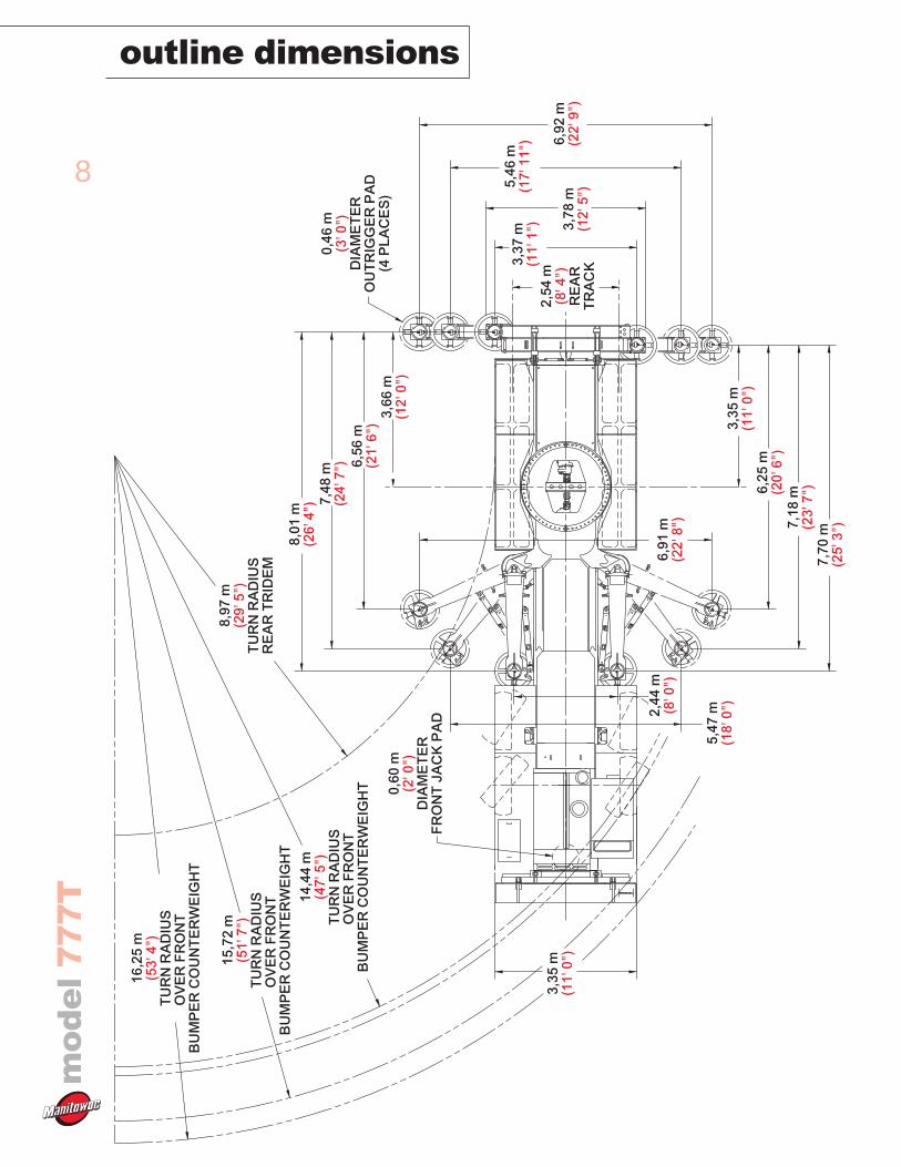
outline dimensions
18,7
1 m
(61'
5")
12,1
9 m
(40'
0")
0,73
m(2
' 5")
0,75
m(2
' 6")
0,00
m(1
7' 1
1'')
WIT
HO
UT
FLO
AT
6,25
m(2
0' 6
")C
OU
NT
ER
WE
IGH
TT
AIL
SW
ING
11,4
0 m
(37'
5")
4,23
m(1
3' 1
1")
WIT
H R
EA
RO
UT
RIG
GE
R B
OX
2,72
m(8
' 11"
)
1,47
m(4
' 10"
)0,
74 m
(2' 5
")
0,3
m(1
' 0")
GR
OU
ND
CLE
AR
AN
CE
0,37
m(1
' 3")
5,53
m(1
8' 2
")
1,88
m(6
' 2")
0,27
m(1
0' 1
")
5,03
m(1
6' 6
")
5,03
m(1
6' 6
")
5,03
m(1
6' 6
")
7,04
m(2
3' 1
")W
HE
ELB
AS
E
5,03
m(1
6' 6
")
5,03
m(1
6' 6
")4,63
m(1
5' 3
")
4,12
m(1
3' 7
")
1,47
m(4
' 10"
)
4,09
m(1
3' 5
")W
ITH
RE
AR
OU
TR
IGG
ER
BO
X
5,16
m(1
6' 1
1")
MA
CH
INE
TA
ILS
WIN
G
RO
TA
TIO
N
1,07
m(3
' 6")
BO
OM
HIN
GE
BACK OF CARRIER
BACK OF OUTRIGGER BOX
0,00
m(1
4'14
'')W
ITH
FLO
AT
0,00
m(1
7' 1
5'')
WIT
HO
UT
FLO
AT
0,00
m(1
2' 4
1'')
WIT
HF
LOA
T
8
mo
de
l7
77
Toutline dimensions
0,46
m(3
' 0")
DIA
ME
TE
RO
UT
RIG
GE
R P
AD
(4 P
LAC
ES
)
8,01
m(2
6' 4
") 7,48
m(2
4' 7
") 6,56
m(2
1' 6
")3,
66 m
(12'
0")
6,92
m(2
2' 9
")
5,46
m(1
7' 1
1")
3,78
m(1
2' 5
")
3,37
m(1
1' 1
")2,
54 m
(8' 4
")R
EA
RT
RA
CK
3,35
m(1
1' 0
")6,
25 m
(20'
6")
7,18
m(2
3' 7
")7,
70 m
(25'
3")
6,91
m(2
2' 8
")
5,47
m(1
8' 0
")2,44
m(8
' 0")
3,35
m(1
1' 0
")
14,4
4 m
(47'
5")
TU
RN
RA
DIU
SO
VE
R F
RO
NT
B
UM
PE
R C
OU
NT
ER
WE
IGH
T
8,97
m(2
9' 5
")T
UR
N R
AD
IUS
RE
AR
TR
IDE
M
15,7
2 m
(51'
7")
TU
RN
RA
DIU
SO
VE
R F
RO
NT
B
UM
PE
R C
OU
NT
ER
WE
IGH
T
16,2
5 m
(53'
4")
TU
RN
RA
DIU
SO
VE
R F
RO
NT
B
UM
PE
R C
OU
NT
ER
WE
IGH
T
0,60
m(2
' 0")
DIA
ME
TE
RF
RO
NT
JA
CK
PA
D
9
mo
de
l7
77
T
outline dimensions
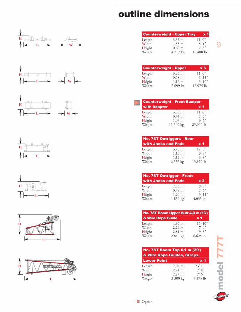
Counterweight - Upper Tray x 1
Length 3,35 m 11' 0"Width 1,55 m 5' 1"Height 0,69 m 2' 3" Weight 4 717 kg 10,400 lb
Counterweight - Upper x 5
Length 3,35 m 11' 0"Width 0,58 m 1' 11"Height 1,16 m 3' 10" Weight 7 699 kg 16,975 lb
Counterweight - Front Bumper with Adapter x 1
Length 3,35 m 11' 0"Width 0,74 m 2' 5"Height 1,07 m 3' 6" Weight 11 340 kg 25,000 lb
No. 78T Outriggers - Rear with Jacks and Pads x 1
Length 3,78 m 12' 5"Width 1,13 m 3' 9"Height 1,12 m 3' 8" Weight 6 336 kg 13,970 lb
No. 78T Outrigger - Front with Jacks and Pads x 2
Length 2,96 m 9' 9"Width 0,78 m 2' 6"Height 1,20 m 3' 11" Weight 1 830 kg 4,035 lb
No. 78T Boom Upper Butt 4,0 m (13')& Wire Rope Guide x 1
Length 4,86 m 15' 10"Width 2,24 m 7' 4"Height 2,81 m 9' 3" Weight 2 840 kg 6,625 lb
No. 78T Boom Top 6,1 m (20')& Wire Rope Guides, Straps,& Wire Rope Guide, Pendants,Lower Point x 1
Length 7,04 m 23' 1"Width 2,24 m 7' 4"Height 2,27 m 7' 6"Weight 3 300 kg 7,275 lb
Option
WL
H
L
H
L
H
L
H
L
H
L
H
L
H
W
W
10
mo
de
l7
77
Toutline dimensions
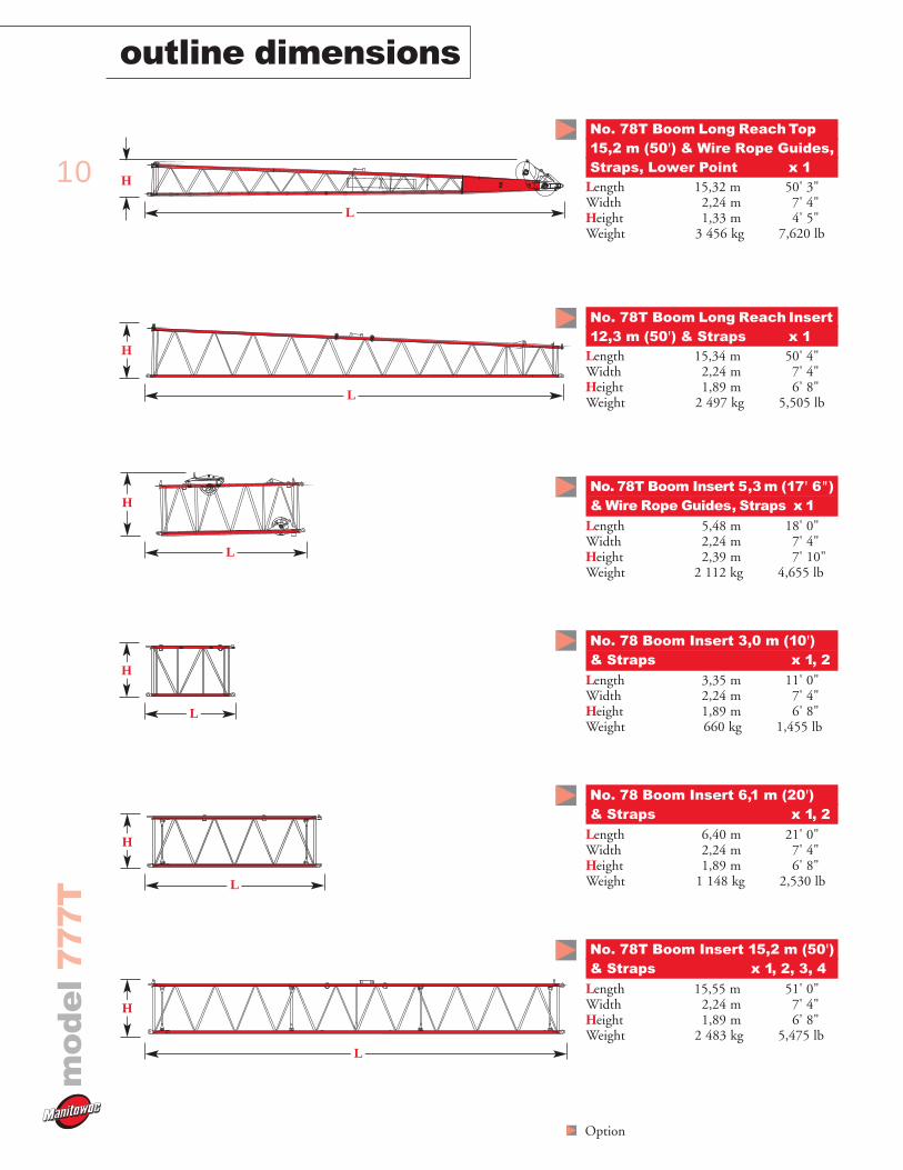
No. 78T Boom Long Reach Top 15,2 m (50') & Wire Rope Guides,Straps, Lower Point x 1
Length 15,32 m 50' 3"Width 2,24 m 7' 4"Height 1,33 m 4' 5" Weight 3 456 kg 7,620 lb
No. 78T Boom Long Reach Insert 12,3 m (50') & Straps x 1
Length 15,34 m 50' 4"Width 2,24 m 7' 4"Height 1,89 m 6' 8"Weight 2 497 kg 5,505 lb
No. 78T Boom Insert 5,3 m (17' 6") & Wire Rope Guides, Straps x 1
Length 5,48 m 18' 0"Width 2,24 m 7' 4"Height 2,39 m 7' 10"Weight 2 112 kg 4,655 lb
No. 78 Boom Insert 3,0 m (10')& Straps x 1, 2
Length 3,35 m 11' 0"Width 2,24 m 7' 4"Height 1,89 m 6' 8"Weight 660 kg 1,455 lb
No. 78 Boom Insert 6,1 m (20')& Straps x 1, 2
Length 6,40 m 21' 0"Width 2,24 m 7' 4"Height 1,89 m 6' 8"Weight 1 148 kg 2,530 lb
No. 78T Boom Insert 15,2 m (50')& Straps x 1, 2, 3, 4
Length 15,55 m 51' 0"Width 2,24 m 7' 4"Height 1,89 m 6' 8"Weight 2 483 kg 5,475 lb
Option
L
H
L
H
L
H
L
H
L
L
H
H
11
mo
de
l7
77
T
outline dimensions
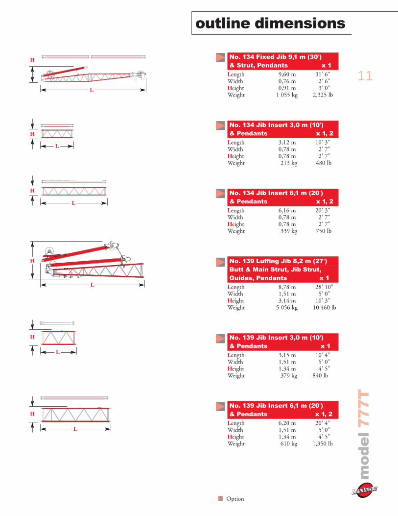
No. 134 Fixed Jib 9,1 m (30')& Strut, Pendants x 1
Length 9,60 m 31' 6"Width 0,76 m 2' 6"Height 0,91 m 3' 0"Weight 1 055 kg 2,325 lb
No. 134 Jib Insert 3,0 m (10')
No. 134 Jib Insert 3,0 m (10')& Pendants x 1, 2
Length 3,12 m 10' 3"Width 0,78 m 2' 7"Height 0,78 m 2' 7"Weight 213 kg 480 lb
No. 134 Jib Insert 6,1 m (20')& Pendants x 1, 2
Length 6,16 m 20' 3"Width 0,78 m 2' 7"Height 0,78 m 2' 7"Weight 339 kg 750 lb
No. 139 Luffing Jib 8,2 m (27')Butt & Main Strut, Jib Strut,Guides, Pendants x 1
Length 8,78 m 28' 10"Width 1,51 m 5' 0"Height 3,14 m 10' 3"Weight 5 056 kg 10,460 lb
No. 139 Jib Insert 3,0 m (10')& Pendants x 1
Length 3,15 m 10' 4"Width 1,51 m 5' 0"Height 1,34 m 4' 5"Weight 379 kg 840 lb
No. 139 Jib Insert 6,1 m (20')& Pendants x 1, 2
Length 6,20 m 20' 4"Width 1,51 m 5' 0"Height 1,34 m 4' 5"Weight 610 kg 1,350 lb
H
L
L
L
H
L
H
H
L
H
Option
L
H
12
mo
de
l7
77
Toutline dimensions
Option
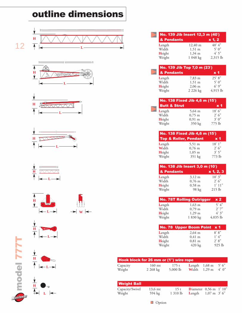
No. 139 Jib Insert 12,3 m (40')& Pendants x 1, 2
Length 12,40 m 40' 4"Width 1,51 m 5' 0"Height 1,34 m 4' 5"Weight 1 048 kg 2,315 lb
No. 139 Jib Top 7,0 m (23')& Pendants x 1
Length 7,83 m 25' 8"Width 1,51 m 5' 0"Height 2,06 m 6' 9"Weight 2 226 kg 4,915 lb
No. 138 Fixed Jib 4,6 m (15')Butt & Strut x 1
Length 5,64 m 18' 6"Width 0,75 m 2' 6"Height 0,91 m 3' 0"Weight 350 kg 775 lb
No. 138 Fixed Jib 4,6 m (15')Top & Roller, Pendant x 1
Length 5,51 m 18' 1"Width 0,76 m 2' 6"Height 1,05 m 3' 5"Weight 351 kg 773 lb
No. 138 Jib Insert 3,0 m (10')& Pendants x 1, 2, 3
Length 3,12 m 10' 3"Width 0,76 m 2' 6"Height 0,58 m 1' 11"Weight 98 kg 215 lb
No. 78T Rolling Outrigger x 2Length 1,63 m 5' 4"Width 0,79 m 2' 7"Height 1,29 m 4' 3" Weight 1 830 kg 4,035 lb
No. 78 Upper Boom Point x 1Length 2,64 m 8' 8"Width 0,41 m 1' 4"Height 0,81 m 2' 8" Weight 420 kg 925 lb
L
H
L
H
L
H
Hook block for 26 mm or (1") wire ropeCapacity 160 mt 175 t Length 1,68 m 5' 6"Weight 2 268 kg 5,000 lb Width 1,29 m 4' 0"
Weight BallCapacity/Swivel 13,6 mt 15 t Diameter 0,56 m 1' 10"Weight 594 kg 1 310 lb Length 1,07 m 3' 6"
L
H
L
H
L
H
W
L
H
L
H
L
H
13
transport data
mo
de
l7
77
T
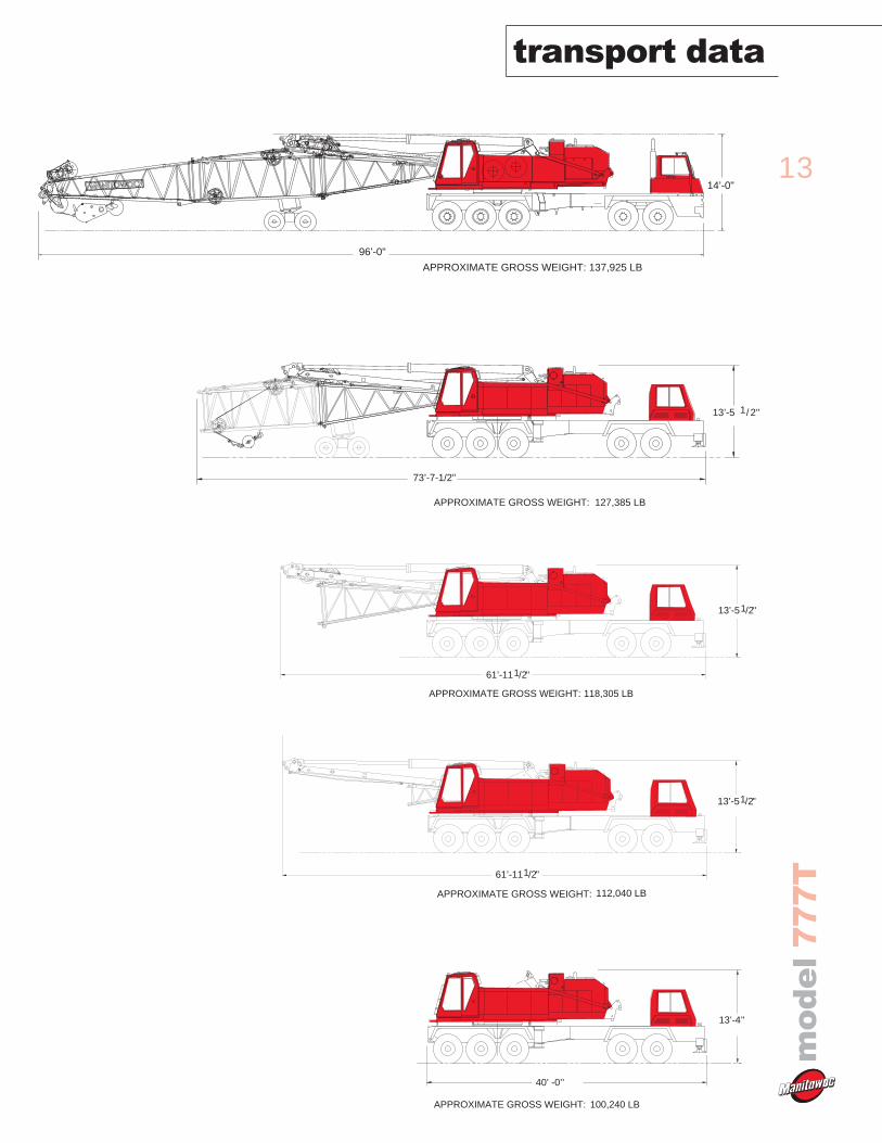
APPROXIMATE GROSS WEIGHT: 137,925 LB
96’-0"
14’-0"
APPROXIMATE GROSS WEIGHT: 127,385 LB
73’-7-1/2"
"2/113’-5
APPROXIMATE GROSS WEIGHT: 118,305 LB
"2/113’-5
"2/161’-11
APPROXIMATE GROSS WEIGHT: 112,040 LB
"2/161’-11
"2/113’-5
APPROXIMATE GROSS WEIGHT: 100,240 LB
"13’-4
40’ -0’’
0
1
1
1
1
1
1
1
2
1
2
1
1
3
2
1
4
2
1
5
1
1
1
1
6
1
2
1
1
1
14
transport datam
od
el
77
7T
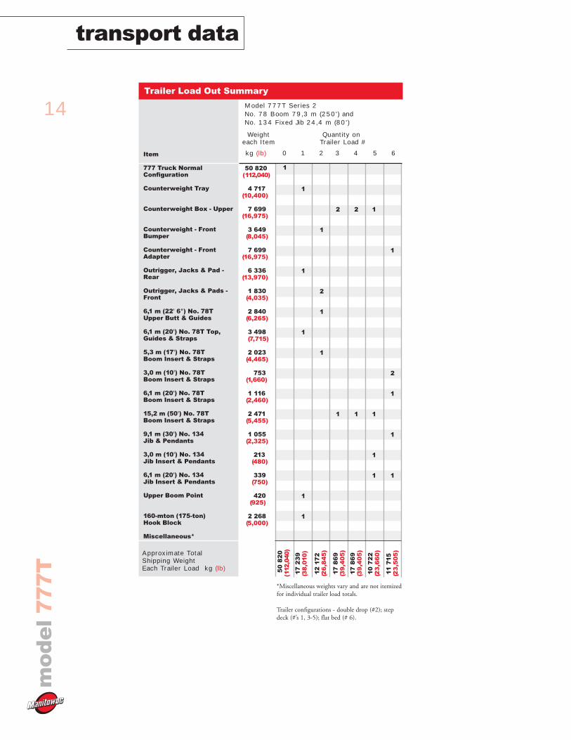
Item
777 Truck NormalConfiguration
Counterweight Tray
Counterweight Box - Upper
Counterweight - FrontBumper
Counterweight - FrontAdapter
Outrigger, Jacks & Pad -Rear
Outrigger, Jacks & Pads -Front
6,1 m (22' 6") No. 78TUpper Butt & Guides
6,1 m (20') No. 78T Top,Guides & Straps
5,3 m (17') No. 78T Boom Insert & Straps
3,0 m (10') No. 78T Boom Insert & Straps
6,1 m (20') No. 78T Boom Insert & Straps
15,2 m (50') No. 78TBoom Insert & Straps
9,1 m (30') No. 134 Jib & Pendants
3,0 m (10') No. 134 Jib Insert & Pendants
6,1 m (20') No. 134 Jib Insert & Pendants
Upper Boom Point
160-mton (175-ton) Hook Block
Miscellaneous*
Approximate Total Shipping WeightEach Trailer Load kg (lb)
kg (lb)
50 820(112,040)
4 717(10,400)
7 699(16,975)
3 649(8,045)
7 699(16,975)
6 336(13,970)
1 830(4,035)
2 840(6,265)
3 498(7,715)
2 023(4,465)
753(1,660)
1 116(2,460)
2 471(5,455)
1 055(2,325)
213(480)
339(750)
420(925)
2 268(5,000)
Trailer Load Out Summary
Model 777T Series 2No. 78 Boom 79,3 m (250') and No. 134 Fixed Jib 24,4 m (80')
Weight Quantity oneach Item Trailer Load #
*Miscellaneous weights vary and are not itemizedfor individual trailer load totals.
Trailer configurations - double drop (#2); stepdeck (#’s 1, 3-5); flat bed (# 6).
50
82
0(1
12,0
40)
17
23
9(3
8,0
10
)
12
17
2(2
6,8
45
)
17
86
9(3
9,4
05
)
17
86
9(3
9,4
05
)
10
72
2(2
3,6
60
)
11
71
5(2
3,5
05
)
15
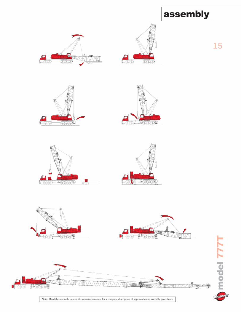
assembly
mo
de
l7
77
T
Note: Read the assembly folio in the operator’s manual for a complete description of approved crane assembly procedures.
16
performance datam
od
el
77
7T
Boom or Boom and Jib
Length
m (ft)
13,0 (42.5)
18,3 (60)
21,3 (70)
24,4 (80)
27,4 (90)
30,5 (100)
33,5 (110)
36,6 (120)
39,6 (130)
42,7 (140)
45,7 (150)
48,8 (160)
51,8 (170)
54,9 (180)
57,9 (190)
61,0 (200)
64,0 (210)
67,1 (220)
70,1 (230)
73,2 (240)
76,2 (250)
79,2 (260)
82,3 (270)
85,3 (280)
88,4 (290)
91,4 (300)
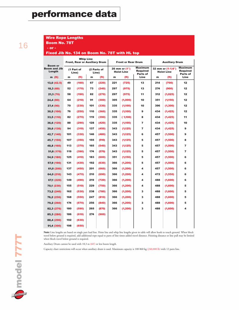
Wire Rope LengthsBoom No. 78T- or -
Fixed Jib No. 134 on Boom No. 78T with HL top
m
49
52
58
64
70
76
82
88
94
101
107
113
119
125
131
137
143
149
155
162
168
174
180
186
192
198
(ft)
(160)
(170)
(190)
(210)
(230)
(250)
(270)
(290)
(310)
(330)
(350)
(370)
(390)
(410)
(430)
(450)
(470)
(490)
(510)
(530)
(550)
(570)
(590)
(610)
(630)
(650)
m
221
297
297
305
335
335
335
335
343
343
343
343
343
351
366
366
366
366
366
366
366
366
366
(ft)
(725)
(975)
(975)
(1,000)
(1,100)
(1,100)
( 1,100)
(1,100)
(1,125)
(1,125)
(1,125)
(1,125)
(1,125)
(1,150)
(1,200)
(1,200)
(1,200)
(1,200)
(1,200)
(1,200)
(1,200)
(1,200)
(1,200)
MaximumRequiredParts of
Line
13
13
11
10
10
9
8
7
7
6
5
5
5
5
5
4
4
4
4
3
3
3
3
(1 Part ofLine)
m
67
73
82
91
101
110
119
128
137
146
155
165
174
183
192
201
210
219
229
238
247
256
265
274
(ft)
(220)
(240)
(270)
(300)
(330)
(360)
(390)
(420)
(450)
(480)
(510)
(540)
(570)
(600)
(630)
(660)
(690)
(720)
(750)
(780)
(810)
(840)
(870)
(900)
(2 Parts ofLine)
26 mm or (1")Hoist Line
32 mm or (1-1/4")Hoist Line
m
214
274
312
351
396
434
434
434
434
457
457
457
457
457
457
457
472
488
488
488
488
488
488
(ft)
(700)
(900)
(1,025)
(1,150)
(1,300)
(1,425)
(1,425)
(1,425)
(1,425)
(1,500)
(1,500)
(1,500)
(1,500)
(1,500)
(1,500)
(1,500)
(1,550)
(1,600)
(1,600)
(1,600)
(1,600)
(1,600)
(1,600)
MaximumRequiredParts of
Line
12
12
12
12
12
12
11
10
9
9
8
7
7
6
6
6
6
6
5
5
5
5
4
Note: Line lengths are based on single part lead line. Hoist line and whip line lengths given in table will allow hook to touch ground. When blocktravel below ground is required, add additional rope equal to parts of line times added travel distance. Hoisting distance or line pull may be limitedwhen block travel below ground is required.
Auxiliary Drum cannot be used with 18,3 m (60') or less boom length.
Capacity chart restrictions will occur when auxiliary drum is used. Maximum capacity is 108 860 kg (240,000 lb) with 12 parts line.
Whip LineFront, Rear or Auxiliary Drum Front or Rear Drum Auxiliary Drum
17
mo
de
l7
77
T
performance data
Boom or Boom and Jib
Length
m (ft)
42,1 (138)
45,1 (148)
48,2 (158)
51,2 (168)
54,3 (178)
57,3 (188)
60,4 (198)
63,4 (208)
66,4 (218)
69,5 (228)
72,5 (238)
75,6 (248)
78,6 (258)
81,7 (268)
84,7 (278)
87,8 (288)
90,8 (298)
93,9 (308)
96,9 (318)
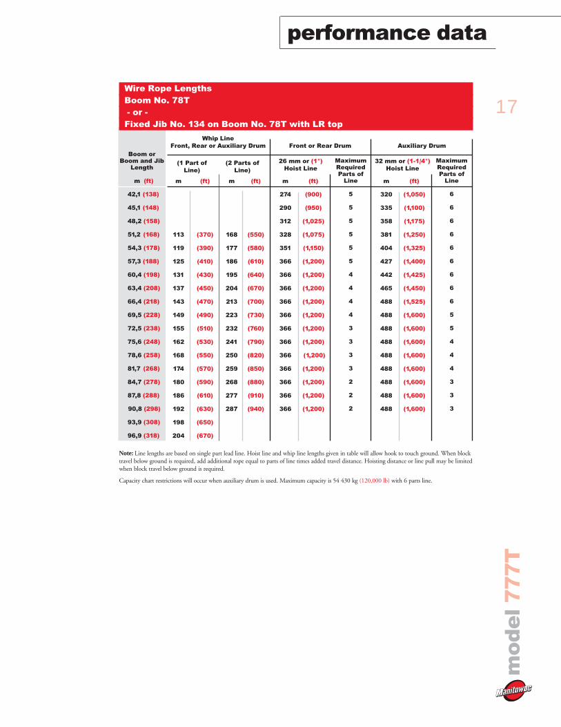
Wire Rope LengthsBoom No. 78T- or -
Fixed Jib No. 134 on Boom No. 78T with LR top
m
113
119
125
131
137
143
149
155
162
168
174
180
186
192
198
204
(ft)
(370)
(390)
(410)
(430)
(450)
(470)
(490)
(510)
(530)
(550)
(570)
(590)
(610)
(630)
(650)
(670)
m
274
290
312
328
351
366
366
366
366
366
366
366
366
366
366
366
366
(ft)
(900)
(950)
(1,025)
(1,075)
(1,150)
(1,200)
(1,200)
(1,200)
(1,200)
(1,200)
(1,200)
(1,200)
(1,200)
(1,200)
(1,200)
(1,200)
(1,200)
MaximumRequiredParts of
Line
5
5
5
5
5
5
4
4
4
4
3
3
3
3
2
2
2
(1 Part ofLine)
m
168
177
186
195
204
213
223
232
241
250
259
268
277
287
(ft)
(550)
(580)
(610)
(640)
(670)
(700)
(730)
(760)
(790)
(820)
(850)
(880)
(910)
(940)
(2 Parts ofLine)
26 mm or (1")Hoist Line
32 mm or (1-1/4")Hoist Line
m
320
335
358
381
404
427
442
465
488
488
488
488
488
488
488
488
488
(ft)
(1,050)
(1,100)
(1,175)
(1,250)
(1,325)
(1,400)
(1,425)
(1,450)
(1,525)
(1,600)
(1,600)
(1,600)
(1,600)
(1,600)
(1,600)
(1,600)
(1,600)
MaximumRequiredParts of
Line
6
6
6
6
6
6
6
6
6
5
5
4
4
4
3
3
3
Note: Line lengths are based on single part lead line. Hoist line and whip line lengths given in table will allow hook to touch ground. When blocktravel below ground is required, add additional rope equal to parts of line times added travel distance. Hoisting distance or line pull may be limitedwhen block travel below ground is required.
Capacity chart restrictions will occur when auxiliary drum is used. Maximum capacity is 54 430 kg (120,000 lb) with 6 parts line.
Whip LineFront, Rear or Auxiliary Drum Front or Rear Drum Auxiliary Drum
18
performance datam
od
el
77
7T
Boom andLuffing Jib
Length
m (ft)
39,6 (130)
42,7 (140)
45,7 (150)
48,8 (160)
51,8 (170)
54,9 (180)
57,9 (190)
61,0 (200)
64,0 (210)
67,1 (220)
70,1 (230)
73,2 (240)
76,2 (250)
79,2 (260)
82,3 (270)
85,3 (280)
88,4 (290)
91,4 (300)
94,5 (310)
97,5 (320)
100,6 (330)
103,6 (340)
106,7 (350)
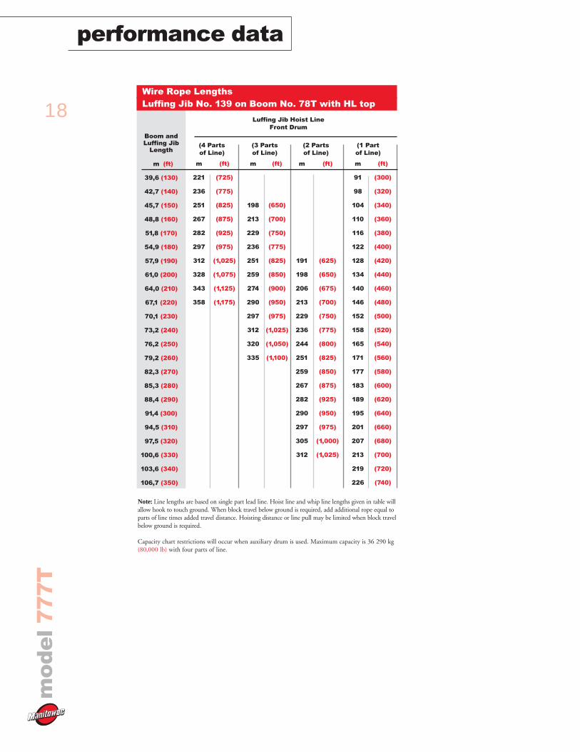
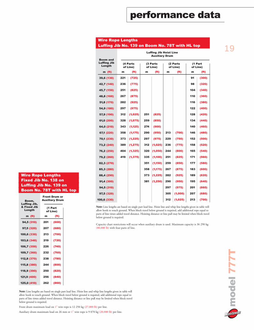
Wire Rope Lengths Luffing Jib No. 139 on Boom No. 78T with HL top
m
221
236
251
267
282
297
312
328
343
358
(ft)
(725)
(775)
(825)
(875)
(925)
(975)
(1,025)
(1,075)
(1,125)
(1,175)
(4 Partsof Line)
m
198
213
229
236
251
259
274
290
297
312
320
335
(ft)
(650)
(700)
(750)
(775)
(825)
(850)
(900)
(950)
(975)
(1,025)
(1,050)
(1,100)
(3 Partsof Line)
m
191
198
206
213
229
236
244
251
259
267
282
290
297
305
312
(ft)
(625)
(650)
(675)
(700)
(750)
(775)
(800)
(825)
(850)
(875)
(925)
(950)
(975)
(1,000)
(1,025)
(2 Partsof Line)
m
91
98
104
110
116
122
128
134
140
146
152
158
165
171
177
183
189
195
201
207
213
219
226
(ft)
(300)
(320)
(340)
(360)
(380)
(400)
(420)
(440)
(460)
(480)
(500)
(520)
(540)
(560)
(580)
(600)
(620)
(640)
(660)
(680)
(700)
(720)
(740)
(1 Partof Line)
Note: Line lengths are based on single part lead line. Hoist line and whip line lengths given in table willallow hook to touch ground. When block travel below ground is required, add additional rope equal toparts of line times added travel distance. Hoisting distance or line pull may be limited when block travelbelow ground is required.
Capacity chart restrictions will occur when auxiliary drum is used. Maximum capacity is 36 290 kg(80,000 lb) with four parts of line.
Luffing Jib Hoist LineFront Drum
19
mo
de
l7
77
T
performance data
Boom andLuffing Jib
Length
m (ft)
39,6 (130)
42,7 (140)
45,7 (150)
48,8 (160)
51,8 (170)
54,9 (180)
57,9 (190)
61,0 (200)
64,0 (210)
67,1 (220)
70,1 (230)
73,2 (240)
76,2 (250)
79,2 (260)
82,3 (270)
85,3 (280)
88,4 (290)
91,4 (300)
94,5 (310)
97,5 (320)
100,6 (330)
Wire Rope Lengths Luffing Jib No. 139 on Boom No. 78T with HL top
m
221
236
251
267
282
297
312
328
343
358
373
389
404
419
(ft)
(725)
(775)
(825)
(875)
(925)
(975)
(1,025)
(1,075)
(1,125)
(1,175)
(1,225)
(1,275)
(1,325)
(1,375)
(4 Partsof Line)
m
251
259
274
290
297
312
320
335
351
358
373
381
(ft)
(825)
(850)
(900)
(950)
(975)
(1,025)
(1,050)
(1,100)
(1,150)
(1,175)
(1,225)
(1,250)
(3 Partsof Line)
m
213
229
236
244
251
259
267
282
290
297
305
312
(ft)
(700)
(750)
(775)
(800)
(825)
(850)
(875)
(925)
(950)
(975)
(1,000)
(1,025)
(2 Partsof Line)
m
91
98
104
110
116
122
128
134
140
146
152
158
165
171
177
183
189
195
201
207
213
(ft)
(300)
(320)
(340)
(360)
(380)
(400)
(420)
(440)
(460)
(480)
(500)
(520)
(540)
(560)
(580)
(600)
(620)
(640)
(660)
(680)
(700)
(1 Partof Line)
Note: Line lengths are based on single part lead line. Hoist line and whip line lengths given in table willallow hook to touch ground. When block travel below ground is required, add additional rope equal toparts of line times added travel distance. Hoisting distance or line pull may be limited when block travelbelow ground is required.
Capacity chart restrictions will occur when auxiliary drum is used. Maximum capacity is 36 290 kg(80,000 lb) with four parts of line.
Luffing Jib Hoist LineAuxiliary Drum
Boom, Luffing Jib, & Fixed Jib
Length
m (ft)
94,5 (310)
97,5 (320)
100,6 (330)
103,6 (340)
106,7 (350)
109,7 (360)
112,8 (370)
115,8 (380)
118,9 (390)
121,9 (400)
125,0 (410)
Wire Rope Lengths Fixed Jib No. 138 onLuffing Jib No. 139 onBoom No. 78T with HL top
m
201
207
213
219
226
232
238
244
250
256
262
(ft)
(600)
(680)
(700)
(720)
(740)
(760)
(780)
(800)
(820)
(840)
(860)
(1 Partof Line)
Note: Line lengths are based on single part lead line. Hoist line and whip line lengths given in table willallow hook to touch ground. When block travel below ground is required, add additional rope equal toparts of line times added travel distance. Hoisting distance or line pull may be limited when block travelbelow ground is required.
Front drum maximum load on 1" wire rope is 12 250 kg (27,000 lb) per line.
Auxiliary drum maximum load on 26 mm or 1" wire rope is 9 070 kg (20,000 lb) per line.
Front Drum orAuxiliary Drum
20
performance datam
od
el
77
7T
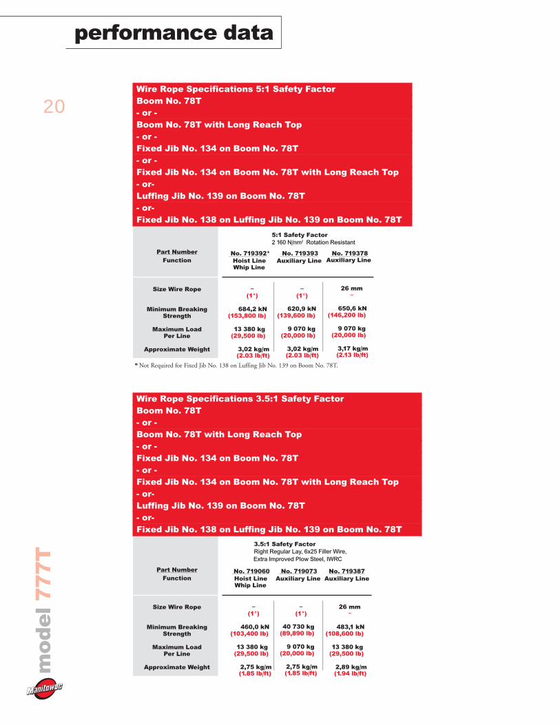
Part NumberFunction
Size Wire Rope
Minimum BreakingStrength
Maximum LoadPer Line
Approximate Weight
No. 719387Auxiliary Line
26 mm–
483,1 kN(108,600 lb)
13 380 kg(29,500 lb)
2,89 kg/m (1.94 lb/ft)
No. 719060Hoist LineWhip Line
–(1")
460,0 kN(103,400 lb)
13 380 kg(29,500 lb)
2,75 kg/m (1.85 lb/ft)
No. 719073Auxiliary Line
–(1")
40 730 kg(89,890 lb)
9 070 kg(20,000 lb)
2,75 kg/m (1.85 lb/ft)
3.5:1 Safety FactorRight Regular Lay, 6x25 Filler Wire,Extra Improved Plow Steel, IWRC
Wire Rope Specifications 3.5:1 Safety FactorBoom No. 78T- or - Boom No. 78T with Long Reach Top- or -Fixed Jib No. 134 on Boom No. 78T - or -Fixed Jib No. 134 on Boom No. 78T with Long Reach Top- or- Luffing Jib No. 139 on Boom No. 78T - or- Fixed Jib No. 138 on Luffing Jib No. 139 on Boom No. 78T
Part NumberFunction
Size Wire Rope
Minimum BreakingStrength
Maximum LoadPer Line
Approximate Weight
No. 719392*Hoist LineWhip Line
–(1")
684,2 kN(153,800 lb)
13 380 kg(29,500 lb)
3,02 kg/m (2.03 lb/ft)
No. 719378Auxiliary Line
26 mm–
650,6 kN(146,200 lb)
9 070 kg(20,000 lb)
3,17 kg/m (2.13 lb/ft)
5:1 Safety Factor2 160 N/nm2 Rotation Resistant
Wire Rope Specifications 5:1 Safety FactorBoom No. 78T- or - Boom No. 78T with Long Reach Top- or -Fixed Jib No. 134 on Boom No. 78T - or -Fixed Jib No. 134 on Boom No. 78T with Long Reach Top- or- Luffing Jib No. 139 on Boom No. 78T - or- Fixed Jib No. 138 on Luffing Jib No. 139 on Boom No. 78T
No. 719393Auxiliary Line
–(1")
620,9 kN(139,600 lb)
9 070 kg(20,000 lb)
3,02 kg/m (2.03 lb/ft)
* Not Required for Fixed Jib No. 138 on Luffing Jib No. 139 on Boom No. 78T.
21
mo
de
l7
77
T
performance data
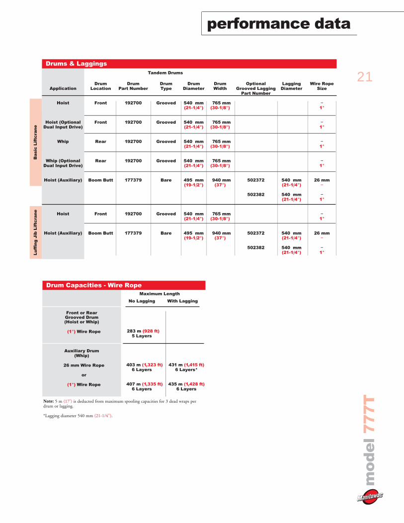
21Front or Rear Grooved Drum (Hoist or Whip)
(1") Wire Rope
Auxiliary Drum (Whip)
26 mm Wire Rope
or
(1") Wire Rope
283 m (928 ft)5 Layers
403 m (1,323 ft)6 Layers
407 m (1,335 ft)6 Layers
431 m (1,415 ft)6 Layers*
435 m (1,428 ft)6 Layers
Drum Capacities - Wire RopeMaximum Length
No Lagging With Lagging
Note: 5 m (17') is deducted from maximum spooling capacities for 3 dead wraps perdrum or lagging.
*Lagging diameter 540 mm (21-1/4").
Ba
sic
Lif
tcra
ne
Lu
ffin
g J
ib L
iftc
ran
e
Ba
sic
L
iftc
ran
e
Application
Hoist
Hoist (OptionalDual Input Drive)
Whip
Whip (OptionalDual Input Drive)
Hoist (Auxiliary)
Hoist
Hoist (Auxiliary)
Drums & LaggingsTandem Drums
DrumLocation
Front
Front
Rear
Rear
Boom Butt
Front
Boom Butt
Drum Part Number
192700
192700
192700
192700
177379
192700
177379
DrumType
Grooved
Grooved
Grooved
Grooved
Bare
Grooved
Bare
DrumDiameter
540 mm(21-1/4")
540 mm(21-1/4")
540 mm(21-1/4")
540 mm(21-1/4")
495 mm(19-1/2")
540 mm(21-1/4")
495 mm(19-1/2")
DrumWidth
765 mm(30-1/8")
765 mm(30-1/8")
765 mm(30-1/8")
765 mm(30-1/8")
940 mm(37")
765 mm(30-1/8")
940 mm(37")
OptionalGrooved Lagging
Part Number
502372
502382
502372
502382
LaggingDiameter
540 mm(21-1/4")
540 mm(21-1/4")
540 mm(21-1/4")
540 mm(21-1/4")
Wire RopeSize
–1"
–1"
–1"
–1"
26 mm–
–1"
–1"
26 mm–
–1"

22
performance datam
od
el
77
7T
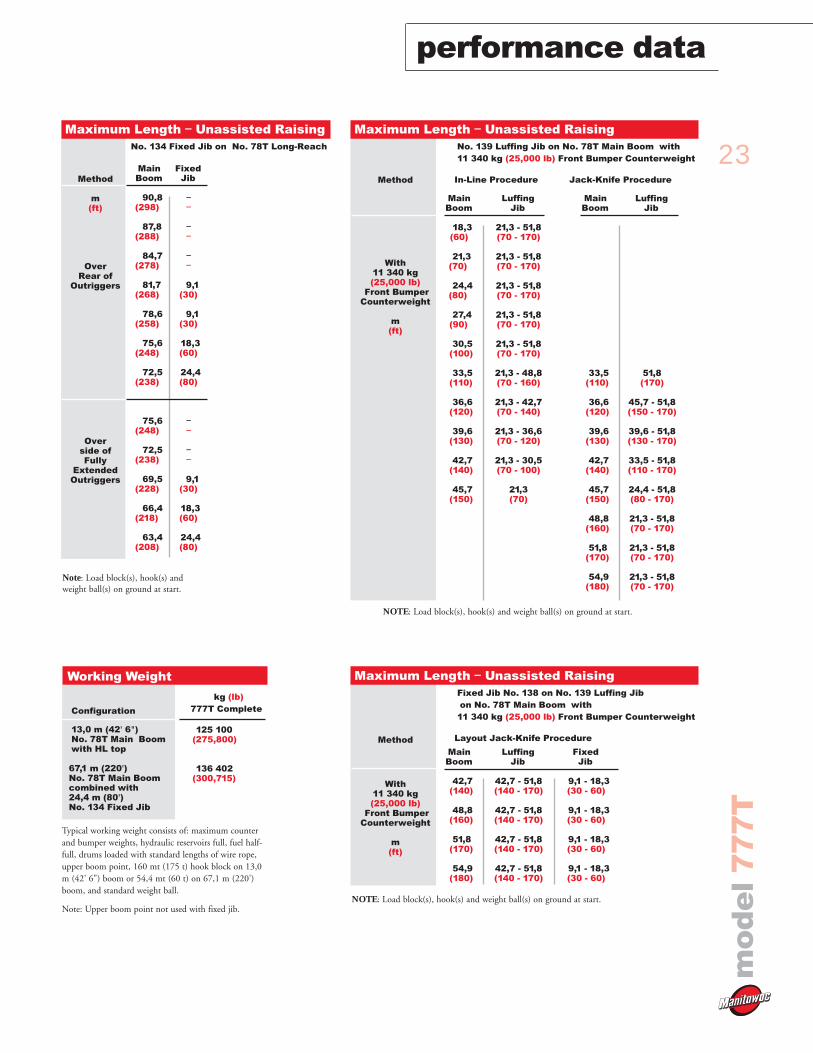
Main Boom
82,3(270)
79,2(260)
76,2(250)
73,2(240)
70,1(230)
67,1(220)
67,1(220)
64,0(210)
61,0(200)
57,9(190)
54,9(180)
Method
m(ft)
OverRear of
Outriggers
Overside ofFully
ExtendedOutriggers
FixedJib
––
––
––
9,1(30)
15,2(50)
24,4 (80)
––
––
9,1(30)
18,3(60)
24,4 (80)
Maximum Length – Unassisted RaisingNo. 134 Fixed Jib on No. 78T Heavy-Lift
Note: Load block(s), hook(s) andweight ball(s) on ground at start.
4
166(543)
148 (485)
105 (345)
74 (242)
58 (190)
49 (160)
43 (141)
2
142(466)
129 (424)
104 (340)
72 (237)
56(185)
47 (154)
42 (136)
1
131 (428)
120(392)
103(337)
71(234)
56(183)
46(152)
41(133)
3
154(505)
139 (455)
104 (342)
73 (239)
57(188)
48 (157)
42 (138)
5
177 (581)
157(515)
106(347)
74 (244)
59 (193)
49 (162)
44 (143)
Layer
Line Pullkg (lb)
0)(0)
2 268)(5,000)
4 536)(10,000)
6 803)(15,000)
9 072)(20,000)
11 340)(25,000)
13 380)(29,500)
Main & Whip Drums - 131 kN (29,500 lb)High Speed Drum - Continuous DutySingle Line Pull/Single Line Speed
m/min (ft/min)
NOTE: Line pull is infinitely variable. With 540 mm (21-1/4") laggingfor 26 mm or (1") wire rope.
4
126(413)
116 (379)
103 (337)
74 (241)
59 (193)
51 (165)
45 (147)
2
108(354)
101 (330)
93 (305)
71 (234)
57(186)
48 (158)
43 (140)
1
99 (325)
93(304)
87(284)
70(231)
56(183)
47(154)
42(137)
3
117(383)
108 (355)
99 (326)
73 (238)
58(190)
49 (161)
44 (144)
5
135 (442)
123(404)
104(340)
75 (245)
60 (197)
51 (168)
46 (151)
Layer
Line Pullkg (lb)
0)(0)
2 268)(5,000)
4 536)(10,000)
6 803)(15,000)
9 072)(20,000)
11 340)(25,000)
13 380)(29,500)
Main & Whip Drums - 131 kN (29,500 lb)Standard Speed Drum - Continuous DutySingle Line Pull/Single Line Speed
m/min (ft/min)
NOTE: Line pull is infinitely variable. With 540 mm (21-1/4") laggingfor 26 mm or (1") wire rope.
23
mo
de
l7
77
T
performance data
Method
With11 340 kg(25,000 lb)
Front BumperCounterweight
m(ft)
Main Boom
18,3(60)
21,3(70)
24,4(80)
27,4(90)
30,5(100)
33,5(110)
36,6(120)
39,6(130)
42,7(140)
45,7(150)
Luffing Jib
21,3 - 51,8(70 - 170)
21,3 - 51,8(70 - 170)
21,3 - 51,8(70 - 170)
21,3 - 51,8(70 - 170)
21,3 - 51,8(70 - 170)
21,3 - 48,8(70 - 160)
21,3 - 42,7(70 - 140)
21,3 - 36,6(70 - 120)
21,3 - 30,5(70 - 100)
21,3(70)
Main Boom
33,5(110)
36,6(120)
39,6(130)
42,7(140)
45,7(150)
48,8(160)
51,8(170)
54,9(180)
Luffing Jib
51,8(170)
45,7 - 51,8(150 - 170)
39,6 - 51,8(130 - 170)
33,5 - 51,8(110 - 170)
24,4 - 51,8(80 - 170)
21,3 - 51,8(70 - 170)
21,3 - 51,8(70 - 170)
21,3 - 51,8(70 - 170)
Maximum Length – Unassisted RaisingNo. 139 Luffing Jib on No. 78T Main Boom with11 340 kg (25,000 lb) Front Bumper Counterweight
In-Line Procedure Jack-Knife Procedure
NOTE: Load block(s), hook(s) and weight ball(s) on ground at start.
Configuration
13,0 m (42' 6")No. 78T Main Boomwith HL top
67,1 m (220')No. 78T Main Boomcombined with24,4 m (80')No. 134 Fixed Jib
125 100(275,800)
136 402(300,715)
Working Weight
kg (lb)777T Complete
Typical working weight consists of: maximum counterand bumper weights, hydraulic reservoirs full, fuel half-full, drums loaded with standard lengths of wire rope,upper boom point, 160 mt (175 t) hook block on 13,0m (42' 6") boom or 54,4 mt (60 t) on 67,1 m (220')boom, and standard weight ball.
Note: Upper boom point not used with fixed jib.
Main Boom
90,8(298)
87,8(288)
84,7(278)
81,7(268)
78,6(258)
75,6(248)
72,5(238)
75,6(248)
72,5(238)
69,5(228)
66,4(218)
63,4(208)
Method
m(ft)
OverRear of
Outriggers
Overside ofFully
ExtendedOutriggers
FixedJib
––
––
––
9,1(30)
9,1(30)
18,3(60)
24,4 (80)
––
––
9,1(30)
18,3(60)
24,4 (80)
Maximum Length – Unassisted RaisingNo. 134 Fixed Jib on No. 78T Long-Reach
Note: Load block(s), hook(s) andweight ball(s) on ground at start.
Method
With11 340 kg(25,000 lb)
Front BumperCounterweight
m(ft)
Main Boom
42,7(140)
48,8(160)
51,8(170)
54,9(180)
Luffing Jib
42,7 - 51,8(140 - 170)
42,7 - 51,8(140 - 170)
42,7 - 51,8(140 - 170)
42,7 - 51,8(140 - 170)
Fixed Jib
9,1 - 18,3(30 - 60)
9,1 - 18,3(30 - 60)
9,1 - 18,3(30 - 60)
9,1 - 18,3(30 - 60)
Maximum Length – Unassisted RaisingFixed Jib No. 138 on No. 139 Luffing Jibon No. 78T Main Boom with
11 340 kg (25,000 lb) Front Bumper Counterweight
Layout Jack-Knife Procedure
NOTE: Load block(s), hook(s) and weight ball(s) on ground at start.
24
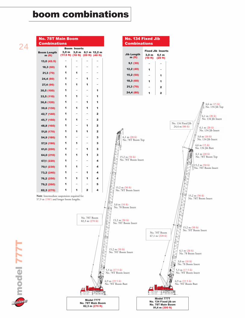
boom combinationsm
od
el
77
7T
Model 777TNo. 134 Fixed jib onNo. 78T Main Boom
91,4 m (300 ft)
6,9 m (22.5 ft)No. 78T Boom Butt
6,1 m (20 ft)No. 78 Boom Insert
15,2 m (50 ft)No. 78T Boom Insert
6,1 m (20 ft)No. 78T Boom Top
No. 78T Boom67,1 m (220 ft)
15,2 m (50 ft)No. 78T Boom Insert
15,2 m (50 ft)No. 78T Boom Insert
Model 777TNo. 78T Main Boom
82,3 m (270 ft)
Boom Lengthm (ft)
13,0 (42.5)
18,3 (60)
21,3 (70)
24,4 (80)
27,4 (90)
30,5 (100)
33,5 (110)
36,6 (120)
39,6 (130)
42,7 (140)
45,7 (150)
48,8 (160)
51,8 (170)
54,9 (180)
57,9 (190)
61,0 (200)
64,0 (210)
67,1 (220)
70,1 (230)
73,2 (240)
76,2 (250)
79,2 (260)
82,3 (270)
3,0 m(10 ft)
–
–
1
–
1
–
1
–
1
–
1
–
1
–
1
–
1
–
1
–
1
–
1
3,0 m(17.5 ft)
–
1
1
1
1
1
1
1
1
1
1
1
1
1
1
1
1
1
1
1
1
1
1
6,1 m(20 ft)
–
–
–
1
1
–
–
1
1
–
–
1
1
–
–
1
1
–
–
1
1
–
2
12,2 m(40 ft)
–
–
–
–
–
1
1
1
1
2
2
2
2
3
3
3
3
4
4
4
4
5
4
Boom Inserts
No. 78T Main Boom Combinations
Note: Intermediate suspension required for57,9 m (190') and longer boom lengths.
Jib Lengthm (ft)
9,1 (30)
12,2 (40)
15,2 (50)
18,3 (60)
21,3 (70)
24,4 (80)
3,0 m(10 ft)
–
1
–
1
–
1
6,1 m(20 ft)
–
–
1
1
2
2
Fixed Jib Inserts
No. 134 Fixed JibCombinations
4,6 m (15 ft)No. 134 Jib Butt
6,1 m (20 ft)No. 134 Jib Insert
4,6 m (15 ft)No. 134 Jib Top
No. 134 Fixed Jib24,4 m (80 ft)
6,1 m (20 ft)No. 134 Jib Insert
3,0 m (10 ft)No. 134 Jib Insert
5,3 m (17.5 ft)No. 78T Boom Insert
3,0 m (10 ft)No. 78 Boom Insert
6,9 m (22.5 ft)No. 78T Boom Butt
15,2 m (50 ft)No. 78T Boom Insert
15,2 m (50 ft)No. 78T Boom Insert
No. 78T Boom82,3 m (270 ft) 15,2 m (50 ft)
No. 78T Boom Insert
15,2 m (50 ft)No. 78T Boom Insert
5,3 m (17.5 ft)No. 78T Boom Insert
3,0 m (10 ft)No. 78 Boom Insert
6,1 m (20 ft)No. 78T Boom Top
25
mo
de
l7
77
T
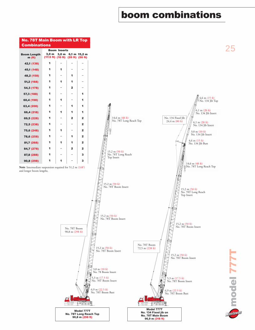
boom combinations
Model 777TNo. 78T Long Reach Top
90,8 m (298 ft)
Model 777TNo. 134 Fixed jib onNo. 78T Main Boom
96,9 m (318 ft)
Boom Lengthm (ft)
42,1 (138)
45,1 (148)
48,2 (158)
51,2 (168)
54,3 (178)
57,3 (188)
60,4 (198)
63,4 (208)
66,4 (218)
69,5 (228)
72,5 (238)
75,6 (248)
78,6 (258)
81,7 (268)
84,7 (278)
87,8 (288)
90,8 (298)
3,0 m(10 ft)
–
1
–
1
–
–
1
–
1
–
–
1
–
1
–
–
1
3,0 m(17.5 ft)
1
1
1
1
1
1
1
1
1
1
1
1
1
1
1
1
1
6,1 m(20 ft)
–
–
1
1
2
–
–
1
1
2
–
–
1
1
2
–
–
15,2 m(50 ft)
–
–
–
–
–
1
1
1
1
2
2
2
2
2
2
3
3
Boom Inserts
No. 78T Main Boom with LR Top Combinations
Note: Intermediate suspension required for 51,2 m (168')and longer boom lengths.
6,9 m (22.5 ft)No. 78T Boom Butt
15,2 m (50 ft)No. 78T Boom Insert
15,2 m (50 ft)No. 78T Boom Insert
No. 78T Boom90,8 m (298 ft)
15,2 m (50 ft)No. 78T Boom Insert
15,2 m (50 ft)No. 78T Long ReachTop Insert
5,3 m (17.5 ft)No. 78T Boom Insert
14,6 m (48 ft)No. 78T Long Reach Top
6,9 m (22.5 ft)No. 78T Boom Butt
15,2 m (50 ft)No. 78T Boom Insert
14,6 m (48 ft)No. 78T Long Reach Top
No. 78T Boom72,5 m (238 ft)
15,2 m (50 ft)No. 78T Boom Insert
15,2 m (50 ft)No. 78T Long ReachTop Insert
4,6 m (15 ft)No. 134 Jib Butt
6,1 m (20 ft)No. 134 Jib Insert
4,6 m (15 ft)No. 134 Jib Top
No. 134 Fixed Jib24,4 m (80 ft)
6,1 m (20 ft)No. 134 Jib Insert
3,0 m (10 ft)No. 134 Jib Insert
5,3 m (17.5 ft)No. 78T Boom Insert
3,0 m (10 ft)No. 78 Boom Insert
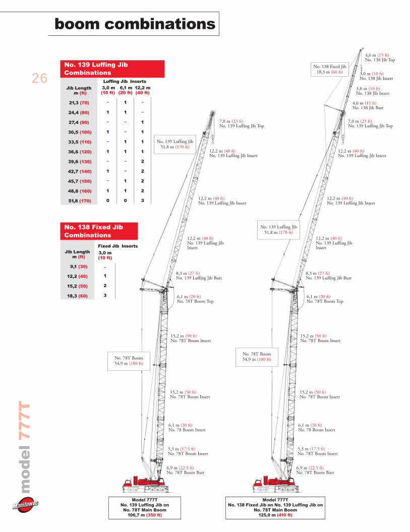
26
boom combinationsm
od
el
77
7T
Model 777TNo. 139 Luffing Jib on
No. 78T Main Boom 106,7 m (350 ft)
Jib Lengthm (ft)
21,3 (70)
24,4 (80)
27,4 (90)
30,5 (100)
33,5 (110)
36,6 (120)
39,6 (130)
42,7 (140)
45,7 (150)
48,8 (160)
51,8 (170)
3,0 m(10 ft)
–
1
–
1
–
1
–
1
–
1
0
6,1 m(20 ft)
1
1
–
–
1
1
–
–
1
1
0
12,2 m(40 ft)
–
–
1
1
1
1
2
2
2
2
3
Luffing Jib Inserts
No. 139 Luffing Jib Combinations
6,9 m (22.5 ft)No. 78T Boom Butt
15,2 m (50 ft)No. 78T Boom Insert
8,3 m (27 ft)No. 139 Luffing Jib Butt
No. 78T Boom54,9 m (180 ft)
15,2 m (50 ft)No. 78T Boom Insert
12,2 m (40 ft)No. 139 Luffing JibInsert
5,3 m (17.5 ft)No. 78T Boom Insert
12,2 m (40 ft)No. 139 Luffing Jib Insert
6,1 m (20 ft)No. 78 Boom Insert
No. 139 Luffing Jib51,8 m (170 ft)
12,2 m (40 ft)No. 139 Luffing Jib Insert
7,0 m (23 ft)No. 139 Luffing Jib Top
6,1 m (20 ft)No. 78T Boom Top
Model 777TNo. 138 Fixed Jib on No. 139 Luffing Jib on
No. 78T Main Boom 125,0 m (410 ft)
6,9 m (22.5 ft)No. 78T Boom Butt
15,2 m (50 ft)No. 78T Boom Insert
8,3 m (27 ft)No. 139 Luffing Jib Butt
No. 78T Boom54,9 m (180 ft)
15,2 m (50 ft)No. 78T Boom Insert
12,2 m (40 ft)No. 139 Luffing JibInsert
5,3 m (17.5 ft)No. 78T Boom Insert
12,2 m (40 ft)No. 139 Luffing Jib Insert
6,1 m (20 ft)No. 78 Boom Insert
No. 139 Luffing Jib51,8 m (170 ft)
12,2 m (40 ft)No. 139 Luffing Jib Insert
7,0 m (23 ft)No. 139 Luffing Jib Top
6,1 m (20 ft)No. 78T Boom Top
Jib Lengthm (ft)
9,1 (30)
12,2 (40)
15,2 (50)
18,3 (60)
3,0 m(10 ft)
–
1
2
3
Fixed Jib Inserts
No. 138 Fixed JibCombinations
4,6 m (15 ft)No. 138 Jib Butt
3,0 m (10 ft)No. 138 Jib Insert
4,6 m (15 ft)No. 138 Jib Top
No. 138 Fixed Jib18,3 m (60 ft)
3,0 m (10 ft)No. 138 Jib Insert
27
mo
de
l7
77
T
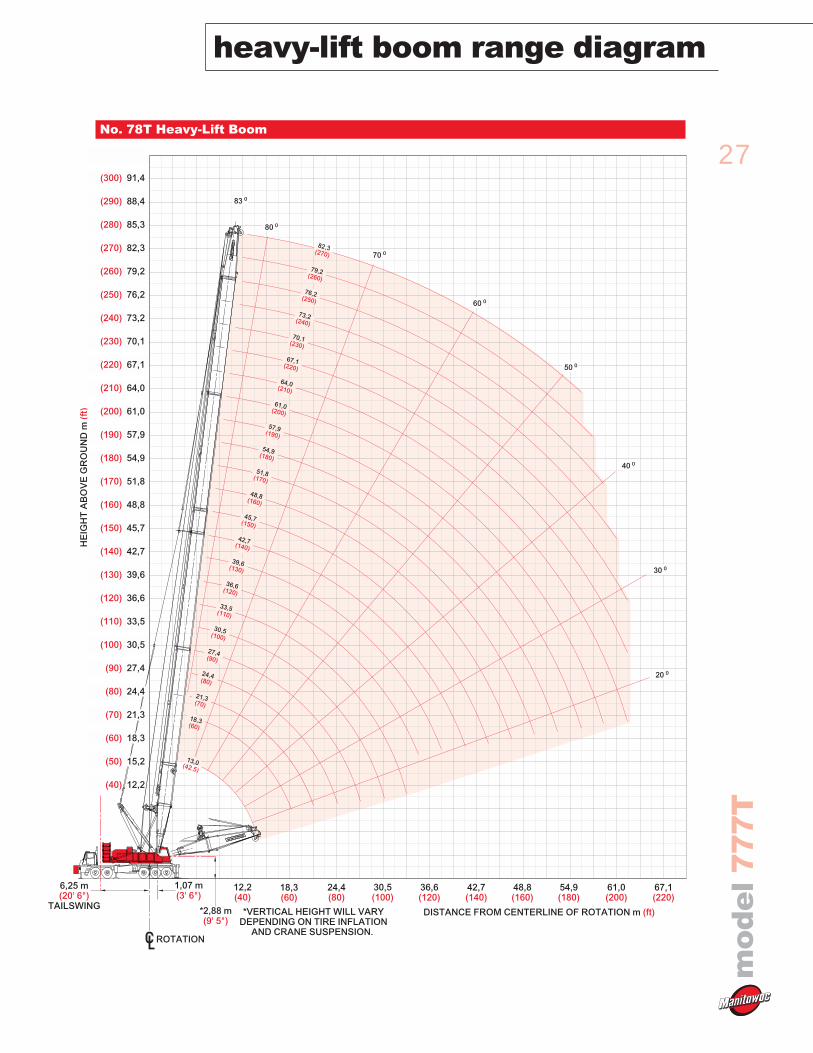
heavy-lift boom range diagram
No. 78T Heavy-Lift Boom
ROTATION
TAILSWING
6,25 m(20' 6")
*2,88 m(9' 5")
1,07 m(3' 6")
*VERTICAL HEIGHT WILL VARYDEPENDING ON TIRE INFLATION
AND CRANE SUSPENSION.
HE
IGH
T A
BO
VE
GR
OU
ND
m (f
t)
(40) 12,2
(200) 61,0
(220) 67,1
(240) 73,2
(260) 79,2
(280) 85,3
(300) 91,4
(180) 54,9
(160) 48,8
(140) 42,7
(120) 36,6
(100) 30,5
(80) 24,4
(60) 18,3
(190) 57,9
(210) 64,0
(230) 70,1
(250) 76,2
(270) 82,3
(290) 88,4
(170) 51,8
(150) 45,7
(130) 39,6
(110) 33,5
(90) 27,4
(70) 21,3
(50) 15,2
DISTANCE FROM CENTERLINE OF ROTATION m (ft)
48,8(160)
54,9(180)
61,0(200)
67,1(220)
42,7(140)
36,6(120)
30,5(100)
24,4(80)
18,3(60)
12,2(40)
80 0
70 0
60 0
50 0
40 0
30 0
20 0
83 0
51,8(170)
57,9(190)
64,0(210)
76,2(250)
45,7(150)
39,6(130)
33,5(110)
48,8(160)
30,5(100)
54,9(180)
36,6(120)
61,0(200)
42,7(140)
18,3(60)
70,1(230)
82,3(270)
24,4(80)
27,4(90)
21,3(70)
73,2(240)
67,1(220)
79,2(260)
13,0(42.5)
28
heavy-lift load chartsm
od
el
77
7T
Meets ANSI B30.5 Requirements - Capacities do not exceed 75% of static tipping load.NOTICE: This capacity chart is for reference only and must not be used for lifting purposes.
Boomft
Radius
12
14
16
20
24
30
40
50
60
70
80
90
100
110
120
130
140
160
180
200
210
220
230
42.5
364.0
354.9
312.8
252.1
210.4
165.4
118.8
70
294.3
252.1
210.6
166.2
120.1
92.8
74.6
61.6
90
247.5
210.3
166.2
120.1
92.8
72.5
57.7
47.1
39.0
110
208.8
185.8
158.8
119.7
92.5
74.5
61.7
52.1
44.7
38.7
33.6
130
168.9
145.7
115.5
92.3
72.7
57.8
47.3
39.4
33.3
28.4
24.3
20.8
150
148.0
112.0
90.7
73.3
60.6
51.0
43.6
37.7
32.8
28.8
25.4
22.4
170
142.3
106.9
86.2
71.8
56.9
46.3
38.4
32.2
27.3
23.3
20.0
17.1
12.5
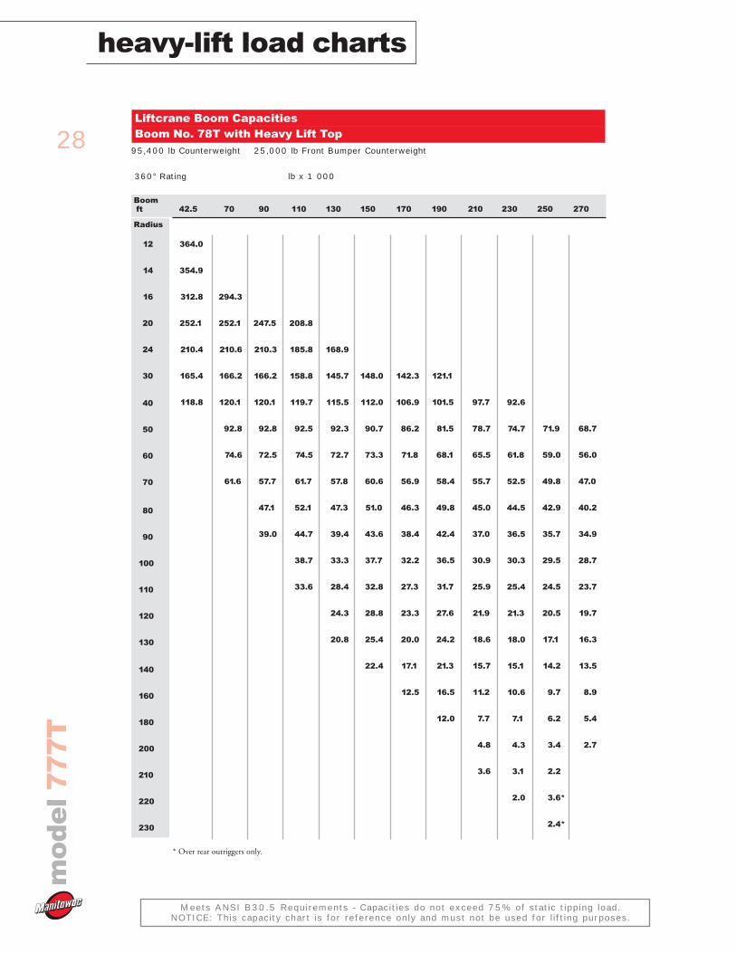
Liftcrane Boom CapacitiesBoom No. 78T with Heavy Lift Top
95,400 lb Counterweight 25,000 lb Front Bumper Counterweight
360° Rating lb x 1 000
190
121.1
101.5
81.5
68.1
58.4
49.8
42.4
36.5
31.7
27.6
24.2
21.3
16.5
12.0
210
97.7
78.7
65.5
55.7
45.0
37.0
30.9
25.9
21.9
18.6
15.7
11.2
7.7
4.8
3.6
230
92.6
74.7
61.8
52.5
44.5
36.5
30.3
25.4
21.3
18.0
15.1
10.6
7.1
4.3
3.1
2.0
250
71.9
59.0
49.8
42.9
35.7
29.5
24.5
20.5
17.1
14.2
9.7
6.2
3.4
2.2
3.6*
2.4*
270
68.7
56.0
47.0
40.2
34.9
28.7
23.7
19.7
16.3
13.5
8.9
5.4
2.7
* Over rear outriggers only.
29
mo
de
l7
77
T
heavy-lift load charts
Meets ANSI B30.5 Requirements - Capacities do not exceed 75% of static tipping load.NOTICE: This capacity chart is for reference only and must not be used for lifting purposes.
Boomft
Radius
12
14
16
18
20
22
26
30
34
40
45
50
60
70
80
90
100
110
120
130
140
42.5
177.1
166.4
143.6
123.5
108.1
95.7
77.3
64.1
54.2
43.2
35.9
60
161.2
143.5
123.5
108.0
95.7
77.3
64.2
54.4
43.6
36.9
31.5
23.3
70
144.5
124.5
109.0
96.7
78.3
65.3
55.5
44.7
38.0
32.7
24.7
18.9
80
144.7
124.6
109.1
96.8
78.4
65.3
55.6
44.8
38.1
32.8
24.9
19.3
14.9
90
124.7
109.2
96.9
78.5
65.4
55.6
44.8
38.1
32.8
25.0
19.4
15.2
11.7
100
124.6
109.1
96.8
78.3
65.2
55.4
44.6
38.0
32.7
24.8
19.3
15.1
11.8
9.1
110
109.1
96.7
78.2
65.1
55.3
44.5
37.9
32.6
24.7
19.2
15.0
11.8
9.2
6.9
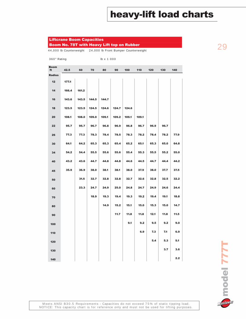
Liftcrane Boom CapacitiesBoom No. 78T with Heavy Lift top on Rubber
44,000 lb Counterweight 24,000 lb Front Bumper Counterweight
360° Rating lb x 1 000
120
96.9
78.4
65.3
55.5
44.7
38.0
32.8
24.9
19.4
15.3
12.1
9.5
7.3
5.4
130
96.7
78.2
65.0
55.2
44.4
37.7
32.5
24.6
19.1
15.0
11.8
9.2
7.1
5.3
3.7
140
77.9
64.8
55.0
44.2
37.5
32.2
24.4
18.8
14.7
11.5
9.0
6.9
5.1
3.6
2.2
30
heavy-lift load chartsm
od
el
77
7T
Meets ANSI B30.5 Requirements - Capacities do not exceed 75% of static tipping load.NOTICE: This capacity chart is for reference only and must not be used for lifting purposes.
Boomft
Radius
12
14
16
18
20
22
26
30
34
40
45
50
60
70
80
90
100
110
120
130
140
145
150
42.5
364.0
354.9
312.8
279.4
252.1
229.5
194.1
153.3
124.1
95.5
79.1
60
353.7
311.8
278.5
251.3
228.8
193.5
154.7
125.3
96.7
80.7
68.8
52.0
70
294.3
279.3
252.1
229.6
194.0
156.0
126.6
97.9
81.9
70.0
53.4
42.3
80
280.6
276.5
252.0
229.4
194.3
156.5
127.0
98.3
82.2
70.2
53.7
42.7
34.8
90
265.3
247.5
229.3
194.1
156.9
127.3
98.5
82.4
70.4
53.9
43.0
35.2
29.2
100
241.2
225.8
211.9
188.7
157.1
127.5
98.6
82.5
70.5
53.9
43.0
35.2
29.3
24.7
110
208.8
196.7
176.0
157.3
127.7
98.7
82.5
70.5
53.9
43.0
35.2
29.4
24.8
21.1
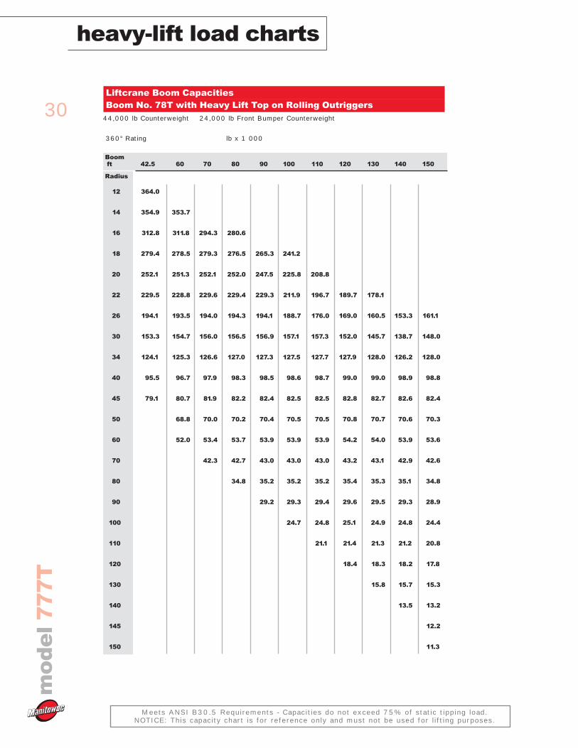
Liftcrane Boom CapacitiesBoom No. 78T with Heavy Lift Top on Rolling Outriggers
44,000 lb Counterweight 24,000 lb Front Bumper Counterweight
360° Rating lb x 1 000
120
189.7
169.0
152.0
127.9
99.0
82.8
70.8
54.2
43.2
35.4
29.6
25.1
21.4
18.4
130
178.1
160.5
145.7
128.0
99.0
82.7
70.7
54.0
43.1
35.3
29.5
24.9
21.3
18.3
15.8
140
153.3
138.7
126.2
98.9
82.6
70.6
53.9
42.9
35.1
29.3
24.8
21.2
18.2
15.7
13.5
150
161.1
148.0
128.0
98.8
82.4
70.3
53.6
42.6
34.8
28.9
24.4
20.8
17.8
15.3
13.2
12.2
11.3
31
mo
de
l7
77
T
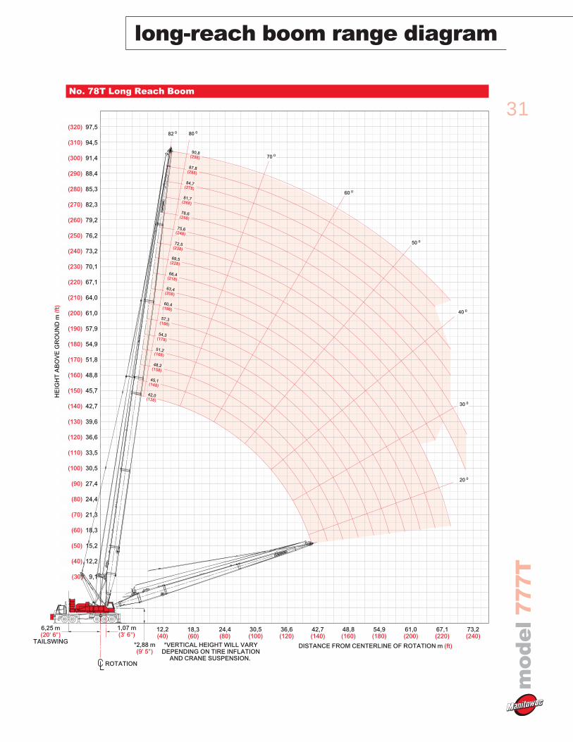
long-reach boom range diagram
No. 78T Long Reach Boom
ROTATION
TAILSWING
6,25 m(20' 6")
*2,88 m(9' 5")
1,07 m(3' 6")
*VERTICAL HEIGHT WILL VARYDEPENDING ON TIRE INFLATION
AND CRANE SUSPENSION.
HE
IGH
T A
BO
VE
GR
OU
ND
m (f
t)
(40) 12,2
(200) 61,0
(220) 67,1
(240) 73,2
(260) 79,2
(280) 85,3
(300) 91,4
(320) 97,5
(180) 54,9
(160) 48,8
(140) 42,7
(120) 36,6
(100) 30,5
(80) 24,4
(60) 18,3
(30) 9,1
(190) 57,9
(210) 64,0
(230) 70,1
(250) 76,2
(270) 82,3
(290) 88,4
(310) 94,5
(170) 51,8
(150) 45,7
(130) 39,6
(110) 33,5
(90) 27,4
(70) 21,3
(50) 15,2
DISTANCE FROM CENTERLINE OF ROTATION m (ft)
48,8(160)
54,9(180)
61,0(200)
67,1(220)
73,2(240)
42,7(140)
36,6(120)
30,5(100)
24,4(80)
18,3(60)
12,2(40)
70 0
60 0
50 0
40 0
30 0
20 0
80 082 0
60,4(198)
66,4(218)
72,5(238)
54,3(178)
48,2(158)
42,0(138)
57,3(188)
63,4(208)
45,1(148)
69,5(228)
51,2(168)
75,6(248)
81,7(268)
87,8(288)
78,6(258)
84,7(278)
90,8(298)
32
long-reach load chartsm
od
el
77
7T
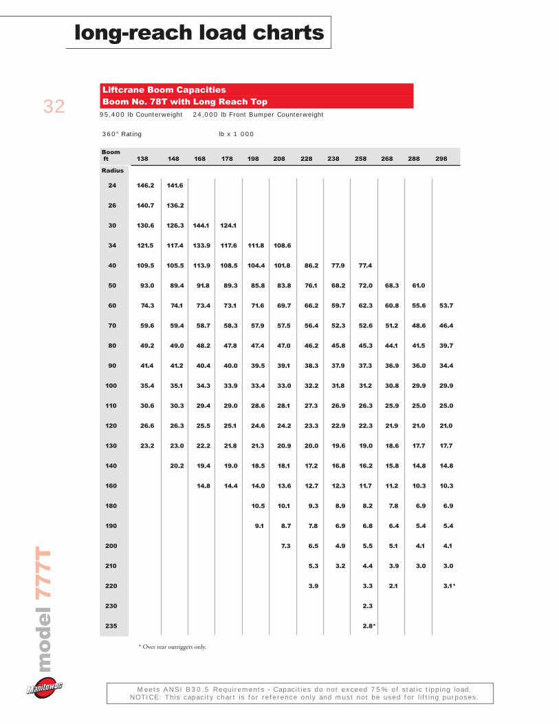
Meets ANSI B30.5 Requirements - Capacities do not exceed 75% of static tipping load.NOTICE: This capacity chart is for reference only and must not be used for lifting purposes.
Boomft
Radius
24
26
30
34
40
50
60
70
80
90
100
110
120
130
140
160
180
190
200
210
220
230
235
138
146.2
140.7
130.6
121.5
109.5
93.0
74.3
59.6
49.2
41.4
35.4
30.6
26.6
23.2
148
141.6
136.2
126.3
117.4
105.5
89.4
74.1
59.4
49.0
41.2
35.1
30.3
26.3
23.0
20.2
168
144.1
133.9
113.9
91.8
73.4
58.7
48.2
40.4
34.3
29.4
25.5
22.2
19.4
14.8
178
124.1
117.6
108.5
89.3
73.1
58.3
47.8
40.0
33.9
29.0
25.1
21.8
19.0
14.4
198
111.8
104.4
85.8
71.6
57.9
47.4
39.5
33.4
28.6
24.6
21.3
18.5
14.0
10.5
9.1
208
108.6
101.8
83.8
69.7
57.5
47.0
39.1
33.0
28.1
24.2
20.9
18.1
13.6
10.1
8.7
7.3
228
86.2
76.1
66.2
56.4
46.2
38.3
32.2
27.3
23.3
20.0
17.2
12.7
9.3
7.8
6.5
5.3
3.9
Liftcrane Boom CapacitiesBoom No. 78T with Long Reach Top
95,400 lb Counterweight 24,000 lb Front Bumper Counterweight
360° Rating lb x 1 000
238
77.9
68.2
59.7
52.3
45.8
37.9
31.8
26.9
22.9
19.6
16.8
12.3
8.9
6.9
4.9
3.2
258
77.4
72.0
62.3
52.6
45.3
37.3
31.2
26.3
22.3
19.0
16.2
11.7
8.2
6.8
5.5
4.4
3.3
2.3
2.8*
268
68.3
60.8
51.2
44.1
36.9
30.8
25.9
21.9
18.6
15.8
11.2
7.8
6.4
5.1
3.9
2.1
288
61.0
55.6
48.6
41.5
36.0
29.9
25.0
21.0
17.7
14.8
10.3
6.9
5.4
4.1
3.0
298
53.7
46.4
39.7
34.4
29.9
25.0
21.0
17.7
14.8
10.3
6.9
5.4
4.1
3.0
3.1*
* Over rear outriggers only.
33
mo
de
l7
77
T
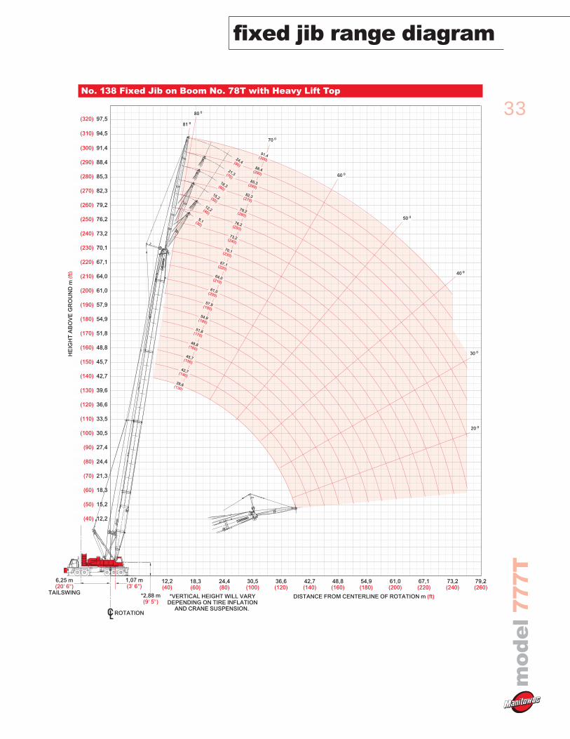
fixed jib range diagram
No. 138 Fixed Jib on Boom No. 78T with Heavy Lift Top
ROTATION
TAILSWING
6,25 m(20' 6")
*2,88 m(9' 5")
1,07 m(3' 6")
*VERTICAL HEIGHT WILL VARYDEPENDING ON TIRE INFLATION
AND CRANE SUSPENSION.
HE
IGH
T A
BO
VE
GR
OU
ND
m (f
t)
(40) 12,2
(200) 61,0
(220) 67,1
(240) 73,2
(260) 79,2
(280) 85,3
(300) 91,4
(180) 54,9
(160) 48,8
(140) 42,7
(120) 36,6
(100) 30,5
(80) 24,4
(60) 18,3
(190) 57,9
(210) 64,0
(230) 70,1
(250) 76,2
(270) 82,3
(290) 88,4
(170) 51,8
(150) 45,7
(130) 39,6
(110) 33,5
(90) 27,4
(70) 21,3
(50) 15,2
DISTANCE FROM CENTERLINE OF ROTATION m (ft)
48,8(160)
54,9(180)
61,0(200)
67,1(220)
42,7(140)
36,6(120)
30,5(100)
24,4(80)
18,3(60)
12,2(40)
79,2(260)
73,2(240)
(320) 97,5
(310) 94,5
80 0
70 0
60 0
50 0
40 0
30 0
20 0
81 0
51,8(170)
57,9(190)
64,0(210)
76,2(250)
45,7(150)
39,6(130)
48,8(160)
54,9(180)
61,0(200)
42,7(140)
70,1(230)
73,2(240)
67,1(220)
79,2(260)
85,3(280)
91,4(300)
82,3(270)
88,4(290)
9,1(30)
12,2(40)
18,3(60)
24,4(80)21,3(70)
15,2(50)
34
fixed jib load chartsm
od
el
77
7T
Meets ANSI B30.5 Requirements - Capacities do not exceed 75% of static tipping load.NOTICE: This capacity chart is for reference only and must not be used for lifting purposes.
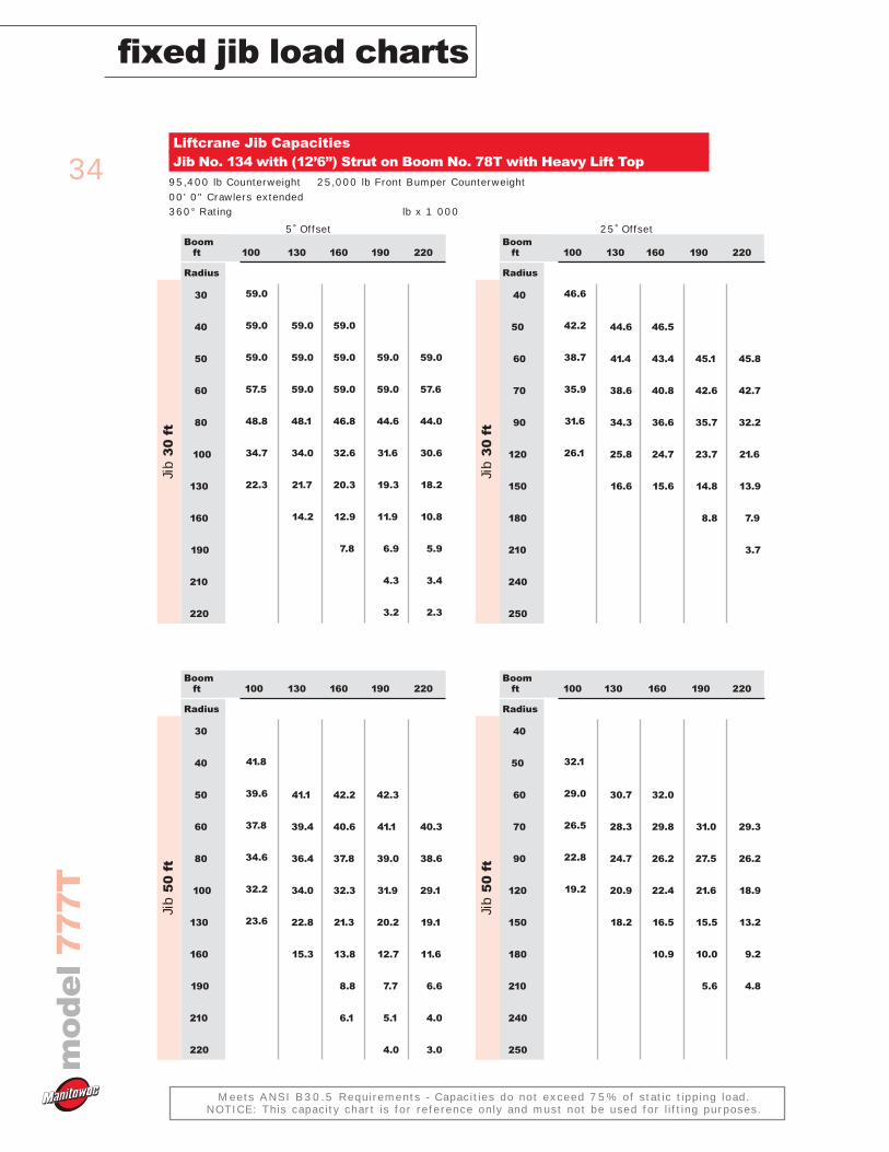
Liftcrane Jib CapacitiesJib No. 134 with (12’6”) Strut on Boom No. 78T with Heavy Lift Top
95,400 lb Counterweight 25,000 lb Front Bumper Counterweight00' 0" Crawlers extended 360° Rating lb x 1 000
5˚ Offset 25˚ Offset
100
59.0
59.0
59.0
57.5
48.8
34.7
22.3
130
59.0
59.0
59.0
48.1
34.0
21.7
14.2
160
59.0
59.0
59.0
46.8
32.6
20.3
12.9
7.8
Boomft
Radius
30
40
50
60
80
100
130
160
190
210
220
Jib
30
ft
190
59.0
59.0
44.6
31.6
19.3
11.9
6.9
4.3
3.2
220
59.0
57.6
44.0
30.6
18.2
10.8
5.9
3.4
2.3
100
46.6
42.2
38.7
35.9
31.6
26.1
130
44.6
41.4
38.6
34.3
25.8
16.6
160
46.5
43.4
40.8
36.6
24.7
15.6
Boomft
Radius
40
50
60
70
90
120
150
180
210
240
250
Jib
30
ft
190
45.1
42.6
35.7
23.7
14.8
8.8
220
45.8
42.7
32.2
21.6
13.9
7.9
3.7
100
41.8
39.6
37.8
34.6
32.2
23.6
130
41.1
39.4
36.4
34.0
22.8
15.3
160
42.2
40.6
37.8
32.3
21.3
13.8
8.8
6.1
Boomft
Radius
30
40
50
60
80
100
130
160
190
210
220
Jib
50
ft
190
42.3
41.1
39.0
31.9
20.2
12.7
7.7
5.1
4.0
220
40.3
38.6
29.1
19.1
11.6
6.6
4.0
3.0
100
32.1
29.0
26.5
22.8
19.2
130
30.7
28.3
24.7
20.9
18.2
160
32.0
29.8
26.2
22.4
16.5
10.9
Boomft
Radius
40
50
60
70
90
120
150
180
210
240
250
Jib
50
ft
190
31.0
27.5
21.6
15.5
10.0
5.6
220
29.3
26.2
18.9
13.2
9.2
4.8
35
mo
de
l7
77
T
fixed jib load charts
Meets ANSI B30.5 Requirements - Capacities do not exceed 75% of static tipping load.NOTICE: This capacity chart is for reference only and must not be used for lifting purposes.
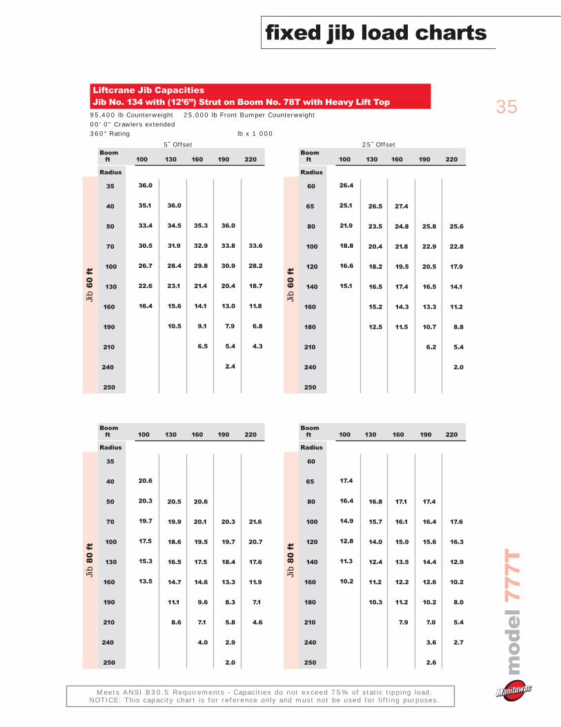
Liftcrane Jib CapacitiesJib No. 134 with (12’6”) Strut on Boom No. 78T with Heavy Lift Top
95,400 lb Counterweight 25,000 lb Front Bumper Counterweight00' 0" Crawlers extended 360° Rating lb x 1 000
5˚ Offset 25˚ Offset
100
36.0
35.1
33.4
30.5
26.7
22.6
16.4
130
36.0
34.5
31.9
28.4
23.1
15.6
10.5
160
35.3
32.9
29.8
21.4
14.1
9.1
6.5
Boomft
Radius
35
40
50
70
100
130
160
190
210
240
250
Jib
60
ft
190
36.0
33.8
30.9
20.4
13.0
7.9
5.4
2.4
220
33.6
28.2
18.7
11.8
6.8
4.3
100
26.4
25.1
21.9
18.8
16.6
15.1
130
26.5
23.5
20.4
18.2
16.5
15.2
12.5
160
27.4
24.8
21.8
19.5
17.4
14.3
11.5
Boomft
Radius
60
65
80
100
120
140
160
180
210
240
250
Jib
60
ft
190
25.8
22.9
20.5
16.5
13.3
10.7
6.2
220
25.6
22.8
17.9
14.1
11.2
8.8
5.4
2.0
100
20.6
20.3
19.7
17.5
15.3
13.5
130
20.5
19.9
18.6
16.5
14.7
11.1
8.6
160
20.6
20.1
19.5
17.5
14.6
9.6
7.1
4.0
Boomft
Radius
35
40
50
70
100
130
160
190
210
240
250
Jib
80
ft
190
20.3
19.7
18.4
13.3
8.3
5.8
2.9
2.0
220
21.6
20.7
17.6
11.9
7.1
4.6
100
17.4
16.4
14.9
12.8
11.3
10.2
130
16.8
15.7
14.0
12.4
11.2
10.3
160
17.1
16.1
15.0
13.5
12.2
11.2
7.9
Boomft
Radius
60
65
80
100
120
140
160
180
210
240
250
Jib
80
ft
190
17.4
16.4
15.6
14.4
12.6
10.2
7.0
3.6
2.6
220
17.6
16.3
12.9
10.2
8.0
5.4
2.7
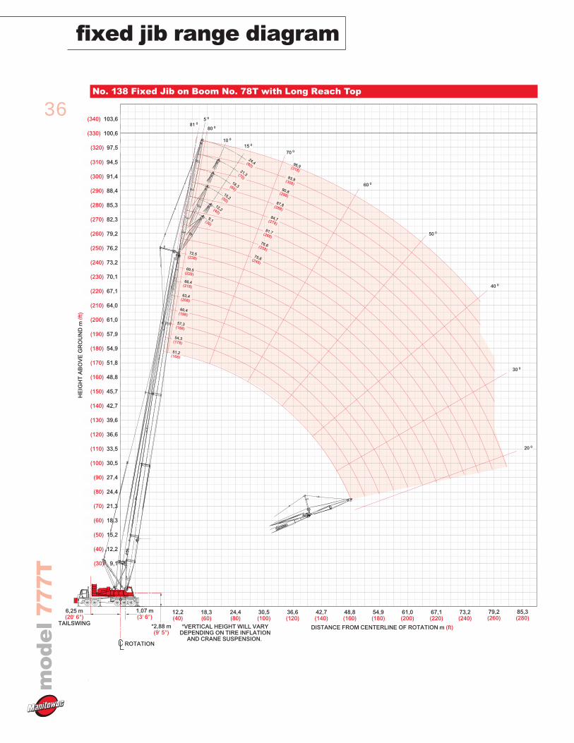
36
fixed jib range diagramm
od
el
77
7T
No. 138 Fixed Jib on Boom No. 78T with Long Reach Top
ROTATION
TAILSWING
6,25 m(20' 6")
*2,88 m(9' 5")
1,07 m(3' 6")
*VERTICAL HEIGHT WILL VARYDEPENDING ON TIRE INFLATION
AND CRANE SUSPENSION.
HE
IGH
T A
BO
VE
GR
OU
ND
m (f
t)
(40) 12,2
(200) 61,0
(220) 67,1
(240) 73,2
(260) 79,2
(280) 85,3
(300) 91,4
(320) 97,5
(180) 54,9
(160) 48,8
(140) 42,7
(120) 36,6
(100) 30,5
(80) 24,4
(60) 18,3
(30) 9,1
(190) 57,9
(210) 64,0
(230) 70,1
(250) 76,2
(270) 82,3
(290) 88,4
(310) 94,5
(170) 51,8
(150) 45,7
(130) 39,6
(110) 33,5
(90) 27,4
(70) 21,3
(50) 15,2
DISTANCE FROM CENTERLINE OF ROTATION m (ft)
48,8(160)
54,9(180)
61,0(200)
67,1(220)
73,2(240)
42,7(140)
36,6(120)
30,5(100)
24,4(80)
18,3(60)
12,2(40)
(320) 97,5
(340) 103,6
(330) 100,6
79,2(260)
85,3(280)
70 0
60 0
50 0
40 0
30 0
20 0
80 081 0
10 0
15 0
5 0
60,4(198)
66,4(218)
72,5(238)
54,3(178)
57,3(188)
63,4(208)
69,5(228)
51,2(168)
75,6(248)
81,7(268)
87,8(288)
78,6(258)
84,7(278)
90,8(298)
93,9(308)
96,9(318)
9,1(30)
12,2(40)
18,3(60)
24,4(80)21,3(70)
15,2(50)
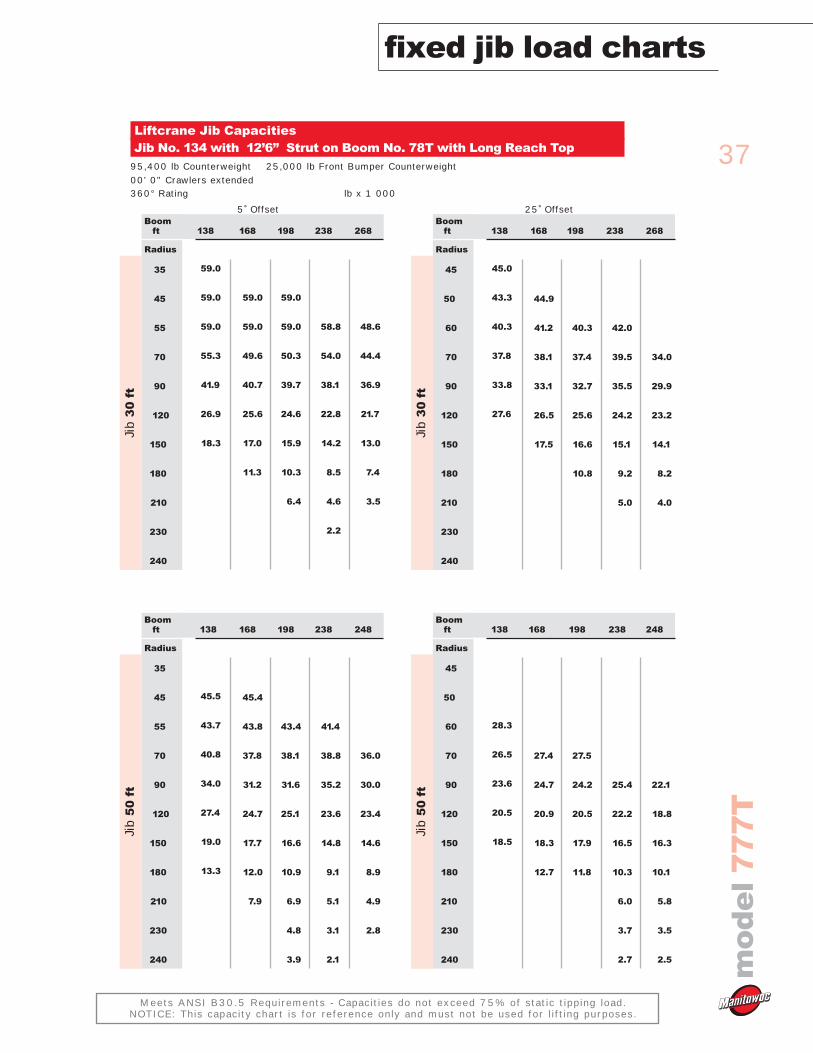
37
mo
de
l7
77
T
fixed jib load charts
Meets ANSI B30.5 Requirements - Capacities do not exceed 75% of static tipping load.NOTICE: This capacity chart is for reference only and must not be used for lifting purposes.
Liftcrane Jib CapacitiesJib No. 134 with 12’6” Strut on Boom No. 78T with Long Reach Top
95,400 lb Counterweight 25,000 lb Front Bumper Counterweight00' 0" Crawlers extended 360° Rating lb x 1 000
5˚ Offset 25˚ Offset
138
59.0
59.0
59.0
55.3
41.9
26.9
18.3
168
59.0
59.0
49.6
40.7
25.6
17.0
11.3
198
59.0
59.0
50.3
39.7
24.6
15.9
10.3
6.4
Boomft
Radius
35
45
55
70
90
120
150
180
210
230
240
Jib
30
ft
238
58.8
54.0
38.1
22.8
14.2
8.5
4.6
2.2
268
48.6
44.4
36.9
21.7
13.0
7.4
3.5
138
45.0
43.3
40.3
37.8
33.8
27.6
168
44.9
41.2
38.1
33.1
26.5
17.5
198
40.3
37.4
32.7
25.6
16.6
10.8
Boomft
Radius
45
50
60
70
90
120
150
180
210
230
240
Jib
30
ft
238
42.0
39.5
35.5
24.2
15.1
9.2
5.0
268
34.0
29.9
23.2
14.1
8.2
4.0
138
45.5
43.7
40.8
34.0
27.4
19.0
13.3
168
45.4
43.8
37.8
31.2
24.7
17.7
12.0
7.9
198
43.4
38.1
31.6
25.1
16.6
10.9
6.9
4.8
3.9
Boomft
Radius
35
45
55
70
90
120
150
180
210
230
240
Jib
50
ft
238
41.4
38.8
35.2
23.6
14.8
9.1
5.1
3.1
2.1
248
36.0
30.0
23.4
14.6
8.9
4.9
2.8
138
28.3
26.5
23.6
20.5
18.5
168
27.4
24.7
20.9
18.3
12.7
198
27.5
24.2
20.5
17.9
11.8
Boomft
Radius
45
50
60
70
90
120
150
180
210
230
240
Jib
50
ft
238
25.4
22.2
16.5
10.3
6.0
3.7
2.7
248
22.1
18.8
16.3
10.1
5.8
3.5
2.5
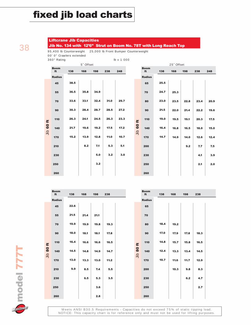
38
fixed jib load chartsm
od
el
77
7T
Meets ANSI B30.5 Requirements - Capacities do not exceed 75% of static tipping load.NOTICE: This capacity chart is for reference only and must not be used for lifting purposes.
Liftcrane Jib CapacitiesJib No. 134 with 12’6” Strut on Boom No. 78T with Long Reach Top
95,400 lb Counterweight 25,000 lb Front Bumper Counterweight00' 0" Crawlers extended 360° Rating lb x 1 000
5˚ Offset 25˚ Offset
138
38.5
36.5
33.6
30.3
26.3
21.7
15.2
168
35.8
33.1
28.4
24.1
19.6
13.9
8.2
198
34.9
32.4
28.7
24.5
19.2
12.8
7.1
5.0
3.2
Boomft
Radius
45
55
70
90
110
140
170
210
230
250
260
Jib
60
ft
238
31.0
28.5
26.3
17.5
11.0
5.3
3.2
248
29.7
27.2
23.3
17.2
10.7
5.1
3.0
138
25.5
24.7
23.0
21.5
19.0
16.4
14.7
168
25.3
23.5
22.0
19.5
16.8
14.9
198
22.8
21.4
19.1
16.5
14.0
9.2
Boomft
Radius
65
70
80
90
110
140
170
200
230
250
260
Jib
60
ft
238
23.4
22.2
20.3
18.0
12.6
7.7
4.1
2.1
248
20.9
19.6
17.5
15.0
12.4
7.5
3.9
2.0
138
22.6
21.5
19.9
18.0
16.4
14.5
13.0
9.9
168
21.4
19.9
18.1
16.6
14.8
13.3
8.5
6.5
198
21.1
19.8
18.1
16.6
14.9
13.0
7.4
5.3
3.6
2.8
Boomft
Radius
45
55
70
90
110
140
170
210
230
250
260
Jib
80
ft
238
19.3
17.8
16.5
14.7
11.2
5.5
3.5
138
18.4
17.0
14.8
12.4
10.7
168
19.2
17.9
15.7
13.3
11.6
10.3
198
17.8
15.8
13.4
11.7
9.8
6.2
Boomft
Radius
65
70
80
90
110
140
170
200
230
250
260
Jib
80
ft
238
18.3
16.5
14.5
12.9
8.3
4.7
2.7
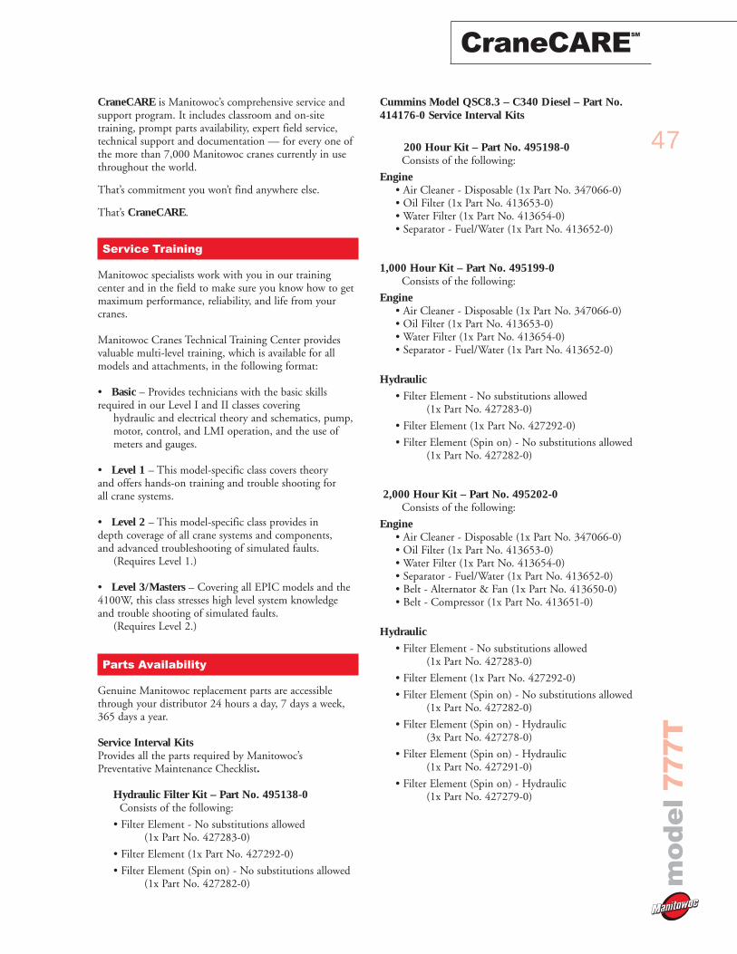
47
CraneCARESM
mo
de
l7
77
T
CraneCARE is Manitowoc’s comprehensive service andsupport program. It includes classroom and on-sitetraining, prompt parts availability, expert field service,technical support and documentation — for every one ofthe more than 7,000 Manitowoc cranes currently in usethroughout the world.
That’s commitment you won’t find anywhere else.
That’s CraneCARE.
Service Training
Manitowoc specialists work with you in our trainingcenter and in the field to make sure you know how to getmaximum performance, reliability, and life from yourcranes.
Manitowoc Cranes Technical Training Center providesvaluable multi-level training, which is available for allmodels and attachments, in the following format:
• Basic – Provides technicians with the basic skills required in our Level I and II classes covering
hydraulic and electrical theory and schematics, pump,motor, control, and LMI operation, and the use of meters and gauges.
• Level 1 – This model-specific class covers theory and offers hands-on training and trouble shooting for all crane systems.
• Level 2 – This model-specific class provides in depth coverage of all crane systems and components, and advanced troubleshooting of simulated faults.
(Requires Level 1.)
• Level 3/Masters – Covering all EPIC models and the 4100W, this class stresses high level system knowledge and trouble shooting of simulated faults.
(Requires Level 2.)
Parts Availability
Genuine Manitowoc replacement parts are accessiblethrough your distributor 24 hours a day, 7 days a week,365 days a year.
Service Interval Kits Provides all the parts required by Manitowoc’sPreventative Maintenance Checklist.
Hydraulic Filter Kit – Part No. 495138-0Consists of the following:
• Filter Element - No substitutions allowed(1x Part No. 427283-0)
• Filter Element (1x Part No. 427292-0)
• Filter Element (Spin on) - No substitutions allowed(1x Part No. 427282-0)
Cummins Model QSC8.3 – C340 Diesel – Part No.414176-0 Service Interval Kits
200 Hour Kit – Part No. 495198-0Consists of the following:
Engine • Air Cleaner - Disposable (1x Part No. 347066-0)• Oil Filter (1x Part No. 413653-0)• Water Filter (1x Part No. 413654-0) • Separator - Fuel/Water (1x Part No. 413652-0)
1,000 Hour Kit – Part No. 495199-0Consists of the following:
Engine • Air Cleaner - Disposable (1x Part No. 347066-0)• Oil Filter (1x Part No. 413653-0)• Water Filter (1x Part No. 413654-0) • Separator - Fuel/Water (1x Part No. 413652-0)
Hydraulic
• Filter Element - No substitutions allowed(1x Part No. 427283-0)
• Filter Element (1x Part No. 427292-0)
• Filter Element (Spin on) - No substitutions allowed(1x Part No. 427282-0)
2,000 Hour Kit – Part No. 495202-0Consists of the following:
Engine • Air Cleaner - Disposable (1x Part No. 347066-0)• Oil Filter (1x Part No. 413653-0)• Water Filter (1x Part No. 413654-0) • Separator - Fuel/Water (1x Part No. 413652-0)• Belt - Alternator & Fan (1x Part No. 413650-0)• Belt - Compressor (1x Part No. 413651-0)
Hydraulic
• Filter Element - No substitutions allowed(1x Part No. 427283-0)
• Filter Element (1x Part No. 427292-0)
• Filter Element (Spin on) - No substitutions allowed(1x Part No. 427282-0)
• Filter Element (Spin on) - Hydraulic(3x Part No. 427278-0)
• Filter Element (Spin on) - Hydraulic(1x Part No. 427291-0)
• Filter Element (Spin on) - Hydraulic(1x Part No. 427279-0)
48
CraneCARESM
mo
de
l7
77
THydraulic Test Kit – Part No. 499791-6Protect your investment by demanding GenuineManitowoc Parts Service Kits. The Hydraulic Service Kitconsist of the following:
• All hydraulic fittings to access all pressures and flows• Hydraulic flow meters and pressure gauges to record
hydraulic data.• Electrical “Break out” harnesses to access voltages on all
electrical circuits on all machines.• Fluke® Digital volt ohm meter, as used in all
Manitowoc service literature.
Hydraulic Test Kit with case – Part No. 499792-9The above kit (Part No. 4299791-6) plus a custom heavy-duty carrying case.
U.S. Standard Tools Kit – Part No. 22205-1All standard tools needed to properly maintain and serviceyour crane. (Does not include torque wrench.)
Carrier Engine Service Kits
Hydraulic Filter Kit – Part No. 495153-0Consists of the following:
• Filter Element (Spin on) - No substitutions allowed(2x Part No. 427282-0)
Detroit Diesel Series 60– Part No. 414167-0 ServiceInterval Kits
200 Hour Kit – Part No. 495154-0Consists of the following:
Engine • Air Cleaner - Disposable (1x Part No. 347066-0)• Oil Filter (1x Part No. 413644-0)• Fuel Filter (1x Part No. 413643-0)
1,000 Hour Kit – Part No. 495155-0Consists of the following:
Engine • Air Cleaner - Disposable (1x Part No. 347066-0)• Oil Filter (1x Part No. 413644-0)• Fuel Filter (1x Part No. 413643-0)
Hydraulic
• Filter Element (Spin on) - No substitutions allowed(2x Part No. 427282-0)
2,000 Hour Kit – Part No. 495156-0Consists of the following:
Engine • Air Cleaner - Disposable (1x Part No. 347066-0)• Oil Filter (1x Part No. 413644-0)• Fuel Filter (1x Part No. 413643-0) • Fuel Filter Strainer (1x Part number not assigned)• Belt - Fan - set of two (1x Part No. 413641-0)• Belt - Alternator - set of two (1x Part No. 413642-0)
Hydraulic
• Filter Element (Spin on) - No substitutions allowed(2x Part No. 427282-0)
Field Service
Factory-trained service experts are always ready to helpmaintain your crane’s peak performance.
For a worldwide listing of dealer locations, please consultour website at: www.manitowoccranegroup.com
Technical Support
Manitowoc’s dealer network and factory personnel areavailable 24 hours a day, 7 days a week, 365 days a year toanswer your technical questions and more, with the helpof computerized programs that simplify crane selection,lift planning, and ground-bearing calculations.
For a worldwide listing of dealer locations, please consultour website at: www.manitowoccranegroup.com
Technical Documentation
Manitowoc has the industry’s most extensivedocumentation, and the easiest to understand, available inmajor languages and formats that include print, disk, andvideotape.
A complete set of Operator’s, Parts, Capacity, Vendor, andService Technician’s Manuals are shipped with each crane.
Additional copies available through your AuthorizedManitowoc Distributor.
• Crane Operator’s Manual – Part No. 899721
• Crane Parts Manual – Part No. 899720
• Crane Capacity Chart Manual – Part No. 899794
• Attachment Capacity Chart Manual
– Part No. 899795
• Crane Vendor Manual – Part No. 899722
• Service Technician’s Manual (EPIC)– Part No. 899732
CD rom versions of the Operator’s and Parts Manuals areshipped with each crane.
Also available are the following CDs:
• 777T Service – Yearly subscriptionCD – Part No. 899760-0
• Ground Bearing Pressure EstimatorCD – Part No. 899765-0
• Crane Selection and Planning Software(CompuCRANE©)CD – Part No. 899766-0
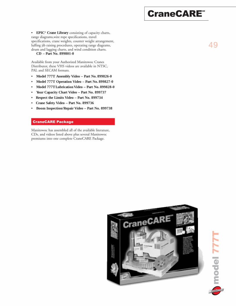
49
CraneCARESM
mo
de
l7
77
T
• EPIC® Crane Library consisting of capacity charts,range diagrams,wire rope specifications, travelspecifications, crane weights, counter weight arrangement,luffing jib raising procedures, operating range diagrams,drum and lagging charts, and wind condition charts.
CD – Part No. 899801-0
Available from your Authorized Manitowoc CranesDistributor, these VHS videos are available in NTSC,PAL and SECAM formats.
• Model 777T Assembly Video – Part No. 899826-0
• Model 777T Operation Video – Part No. 899827-0
• Model 777TLubrication Video – Part No. 899828-0
• Your Capacity Chart Video – Part No. 899737
• Respect the Limits Video – Part No. 899734
• Crane Safety Video – Part No. 899736
• Boom Inspection/Repair Video – Part No. 899738
CraneCARE Package
Manitowoc has assembled all of the available literature,CDs, and videos listed above plus several Manitowocpremiums into one complete CraneCARE Package.
50
Notesm
od
el
77
7T
51
Notes
mo
de
l7
77
T
CraneCARESM
CraneCARE is Manitowoc’s comprehensive service and
support program. It includes classroom and on-site
training, prompt parts availability, expert field service,
technical support and documentation — for every one
of the more than 7,000 Manitowoc cranes currently in
use throughout the world. That’s commitment you won’t
find anywhere else. That’s CraneCARE.
Backed by Manitowoc
Manitowoc Cranes, Inc.P.O. Box 70Manitowoc, WI, USA 54221-0070 Telephone 920-684-6621Facsimile 920-683-6277www.manitowoccranegroup.com
PRODUCT IMPROVEMENTS MAY CHANGE SPECIFICATIONS ©2002 MANITOWOC 0802-777T -PG-US-E -5000