Embed Size (px)
Citation preview
productguide
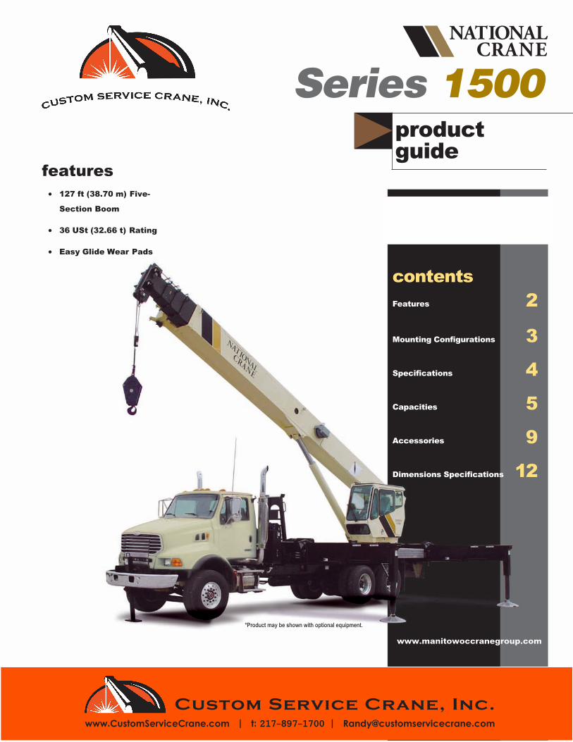
features• 127 ft (38.70 m) Five-
Section Boom
• 36 USt (32.66 t) Rating
• Easy Glide Wear Pads
Series 1500
contentsFeatures 2
Mounting Configurations 3
Specifications 4
Capacities 5
Accessories 9
Dimensions Specifications 12
*Product may be shown with optional equipment.
www.manitowoccranegroup.com
Custom Service Crane, Inc.www.CustomServiceCrane.com | t: 217-897-1700 | [email protected]
features
2
Why Buy a National Crane Series 1500?
1500
• 36 USt (32.66 t) maximumcapacity
• 166 ft (50.60 m) maximumvertical reach*
• 135 ft (41.15 m) maximumvertical hydraulic reach*
• Load Moment Indicator system(LMI)
• Proportional boom extension
• High performance planetarywinch
• Vickers PVH 131 pressurecompensated, load sensing,axial piston, variable volumepump direct mounts to PTO
* Maximum vertical reach isground-level to boom tip heightat maximum extension and anglewith outriggers/stabilizers fullyextended.
• 36 USt (32.66 t) Rating – The 1500 provides a 36 USt (32.66t) capacity at a 6 ft (1.82 m)radius, a 9% increase over the Series 1400.
• 127 ft (38.71 m) Five-section Boom – The long boom allows the operator to perform morelifts without the use of a jib, reducing setup time and improving efficiency.
• Overload Protection – All National Crane boom trucks are equipped with overload protection:– Load Moment Indicator (LMI) standard on all Series 1500 machines.– LMI display and CPU are weatherproof.– LCD display is visible in full or low light.– All crane load lifting values are displayed simultaneously.
• Stronger Torsion Box – The stronger standard torsion box improves rigidity, reduces truckframe flex and reduces the need for counterweight.
• Speedy-reeve Boom Tip and Sheave Blocks – These standard features simplify riggingchanges by decreasing the time needed to change line reeving.
• Pre-painted Components – Painting crane components before assembly reduces thepossibility of rust, improves serviceability and enhances the appearance of the machine.
• Easy Glide Boom Wear Pads – Reduce the conditions that cause boom chatter and vibration.The net result is smoother crane operation.
• Deluxe Operator’s Cab – Rigid galvanized steel structure, well insulated, with ample safetyglass for operator visibility and comfort. Multi-position seat with arm rest controls, ventilationfans, diesel heater, wipers. Optional air-conditioning is available.
• Outrigger – Outrigger span of 24.7 ft (7.53 m) when fully extended; 17.5 ft (5.33 m) at mid-span.– Ground-level outrigger controls on both sides.– In-cab outrigger controls for all functions.– Front bumper stabilizer for stable base over front.
• Improved Serviceability –– Boom sections are supported by one hydraulic extend cylinder, minimizing maintenance.– Bearings on the boom extend and retract cables can be greased through access holes in
the boom side plates.– Pre-paint reduces rust.
• Electronic versions of manuals available through Manitowoc Crane Care.
• New State-of-the-art Control Valve – Provides smoother operation. The new load-sensing,pressure-compensated design greatly enhances function meterability, eliminates parts,reduces repair costs and improves the machine’s serviceability.
• National Crane Is the Market Leader – National Crane is number one in the production ofcommercial truck-mounted boom trucks, with more than 35,000 units sold. National Crane hasmany programs and people directly and indirectly involved to provide our customers withreliable products.
• National Crane has the boom truck industry’s leading test program. Every structural partof the crane is cycle tested, some up to 60,000 cycles at full capacity. In addition to cycletesting, each model is subjected to state-of-the-art strain gauge testing that measures metaldeformation as small as one one-millionth of an inch. The net result is that weak areas arecaught in test, not on job sites where costly downtime occurs.
• Parts are available for all National Crane machines for the life of the crane.
• National Crane has a formalized quality program and is ISO 9001 approved.
*Product may be shown with optional equipment.
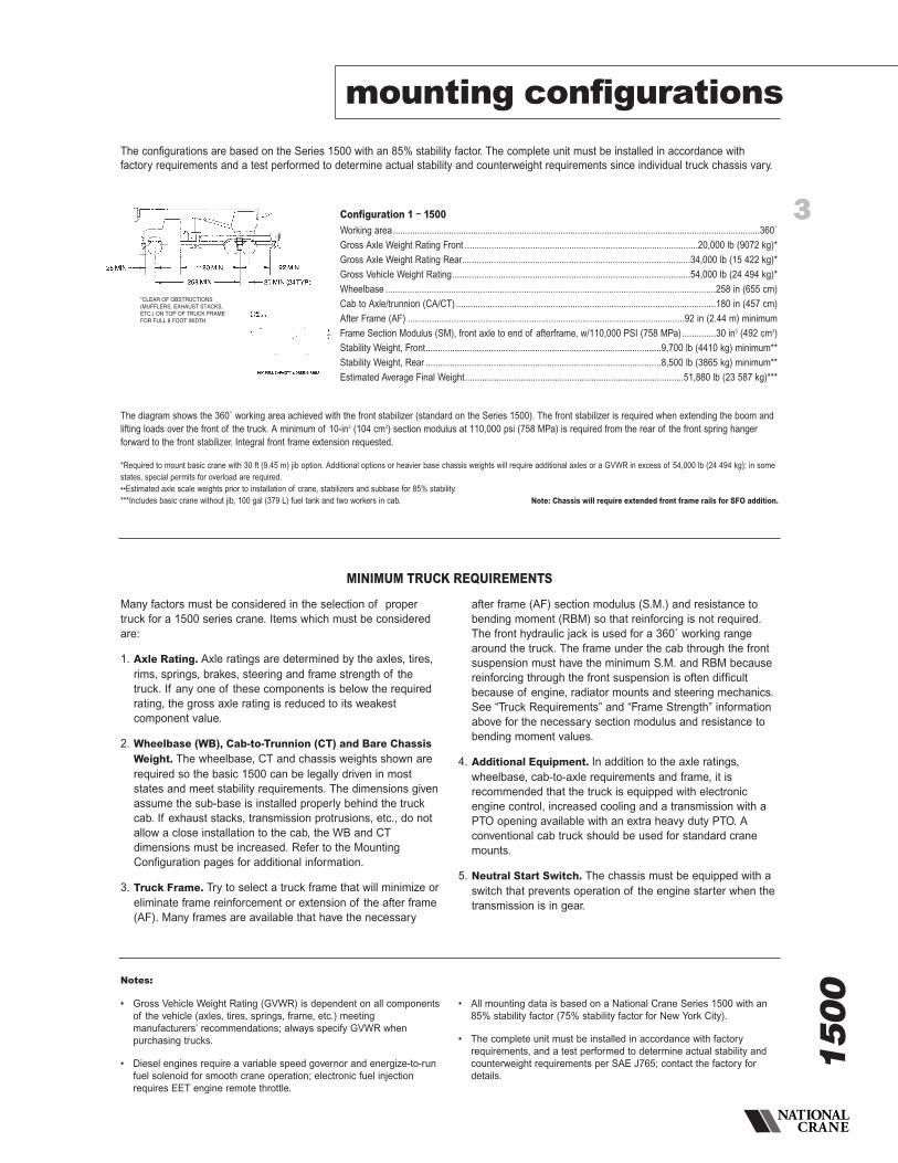
The diagram shows the 360˚ working area achieved with the front stabilizer (standard on the Series 1500). The front stabilizer is required when extending the boom andlifting loads over the front of the truck. A minimum of 10-in3 (104 cm3) section modulus at 110,000 psi (758 MPa) is required from the rear of the front spring hangerforward to the front stabilizer. Integral front frame extension requested.
*Required to mount basic crane with 30 ft (9.45 m) jib option. Additional options or heavier base chassis weights will require additional axles or a GVWR in excess of 54,000 lb (24 494 kg); in somestates, special permits for overload are required.••Estimated axle scale weights prior to installation of crane, stabilizers and subbase for 85% stability.***Includes basic crane without jib, 100 gal (379 L) fuel tank and two workers in cab. Note: Chassis will require extended front frame rails for SFO addition.
3
1500
mounting configurations
Notes:
• Gross Vehicle Weight Rating (GVWR) is dependent on all componentsof the vehicle (axles, tires, springs, frame, etc.) meetingmanufacturers’ recommendations; always specify GVWR whenpurchasing trucks.
• Diesel engines require a variable speed governor and energize-to-runfuel solenoid for smooth crane operation; electronic fuel injectionrequires EET engine remote throttle.
• All mounting data is based on a National Crane Series 1500 with an85% stability factor (75% stability factor for New York City).
• The complete unit must be installed in accordance with factoryrequirements, and a test performed to determine actual stability andcounterweight requirements per SAE J765; contact the factory fordetails.
The configurations are based on the Series 1500 with an 85% stability factor. The complete unit must be installed in accordance withfactory requirements and a test performed to determine actual stability and counterweight requirements since individual truck chassis vary.
Configuration 1 – 1500Working area.......................................................................................................................................................360˚
Gross Axle Weight Rating Front ................................................................................................20,000 lb (9072 kg)*
Gross Axle Weight Rating Rear..............................................................................................34,000 lb (15 422 kg)*
Gross Vehicle Weight Rating..................................................................................................54,000 lb (24 494 kg)*
Wheelbase ........................................................................................................................................258 in (655 cm)
Cab to Axle/trunnion (CA/CT) ...........................................................................................................180 in (457 cm)
After Frame (AF) ..................................................................................................................92 in (2.44 m) minimum
Frame Section Modulus (SM), front axle to end of afterframe, w/110,000 PSI (758 MPa)..............30 in3 (492 cm3)
Stability Weight, Front.................................................................................................9,700 lb (4410 kg) minimum**
Stability Weight, Rear .................................................................................................8,500 lb (3865 kg) minimum**
Estimated Average Final Weight..........................................................................................51,880 lb (23 587 kg)***
*CLEAR OF OBSTRUCTIONS(MUFFLERS, EXHAUST STACKS,ETC.) ON TOP OF TRUCK FRAMEFOR FULL 8 FOOT WIDTH.
MINIMUM TRUCK REQUIREMENTS
Many factors must be considered in the selection of propertruck for a 1500 series crane. Items which must be consideredare:
1. Axle Rating. Axle ratings are determined by the axles, tires,rims, springs, brakes, steering and frame strength of thetruck. If any one of these components is below the requiredrating, the gross axle rating is reduced to its weakestcomponent value.
2. Wheelbase (WB), Cab-to-Trunnion (CT) and Bare ChassisWeight. The wheelbase, CT and chassis weights shown arerequired so the basic 1500 can be legally driven in moststates and meet stability requirements. The dimensions givenassume the sub-base is installed properly behind the truckcab. If exhaust stacks, transmission protrusions, etc., do notallow a close installation to the cab, the WB and CTdimensions must be increased. Refer to the MountingConfiguration pages for additional information.
3. Truck Frame. Try to select a truck frame that will minimize oreliminate frame reinforcement or extension of the after frame(AF). Many frames are available that have the necessary
after frame (AF) section modulus (S.M.) and resistance tobending moment (RBM) so that reinforcing is not required.The front hydraulic jack is used for a 360˚ working rangearound the truck. The frame under the cab through the frontsuspension must have the minimum S.M. and RBM becausereinforcing through the front suspension is often difficultbecause of engine, radiator mounts and steering mechanics.See “Truck Requirements” and “Frame Strength” informationabove for the necessary section modulus and resistance tobending moment values.
4. Additional Equipment. In addition to the axle ratings,wheelbase, cab-to-axle requirements and frame, it isrecommended that the truck is equipped with electronicengine control, increased cooling and a transmission with aPTO opening available with an extra heavy duty PTO. Aconventional cab truck should be used for standard cranemounts.
5. Neutral Start Switch. The chassis must be equipped with aswitch that prevents operation of the engine starter when thetransmission is in gear.
4
1500
specifications
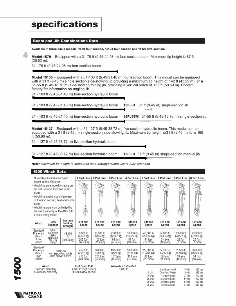
Boom and Jib Combinations Data
1500 Winch Data
Aux Boom Head 100 lb (45 kg)5 USt Downhaul Weight 180 lb (82 kg)
15 USt 1 Sheave Block 375 lb (170 kg)25 USt 2 Sheave Block 640 lb (290 kg)35 USt 3 Sheave Block 870 lb (395 kg)36 USt 4 Sheave Block 970 lb (440 kg)
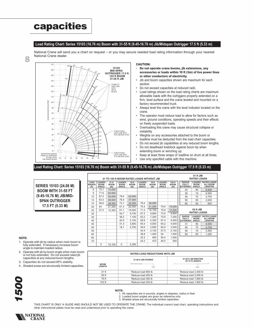
Available in three basic models: 1579 four-section, 15103 four-section and 15127 five-section.
Model 15103 – Equipped with a 31-103 ft (9.45-31.40 m) four-section boom. This model can be equippedwith a 31 ft (9.45 m) single section side-stowing jib providing a maximum tip height of 142 ft (43.29 m), or a31-55 ft (9.45-16.76 m) side-stowing folding jib, providing a vertical reach of 166 ft (50.60 m). Contactfactory for information on angling jib.
31 - 103 ft (9.45-31.40 m) four-section hydraulic boom
Note: maximum tip height is measured with outriggers/stabilizers fully extended.
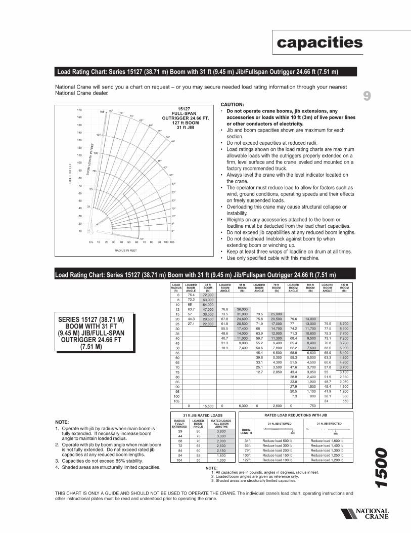
Model 15127 – Equipped with a 31-127 ft (9.45-38.72 m) five-section hydraulic boom. This model can beequipped with a 31 ft (9.45 m) single-section side-stowing jib. Maximum tip height w/31 ft (9.45 m) jib is 166ft (50.60 m).
31 - 127 ft (9.45-38.72 m) five-section hydraulic boom
31 - 127 ft (9.45-38.72 m) five-section hydraulic boom 15FJ31 31 ft (9.45 m) single-section manual jib
31 - 103 ft (9.45-31.40 m) four-section hydraulic boom 15FJ55M 31-55 ft (9.45-16.76 m) single-section jib
31 - 103 ft (9.45-31.40 m) four-section hydraulic boom 15FJ31 31 ft (9.45 m) single-section jib
• All winch pulls and speeds areshown on the fifth layer.
• Winch line pulls would increase onthe first, second, third and fourthlayers.
• Winch line speed would decreaseon the first, second, third and fourthlayers.
• Winch line pulls may be limited bythe winch capacity or the ANSI 5 to1 cable safety factor.
Winch CableSupplied
AverageBreakingSrength
Lift andSpeed
Lift andSpeed
Lift andSpeed
Lift andSpeed
Lift andSpeed
Lift andSpeed
Lift andSpeed
Lift andSpeed
StandardPlanetary
WinchLow
Speed
5/8 indiameterrotationresistant18 x 19IWRC
45,400lb
(20593 kg)
9,000 lb(4082 kg)205 fpm(62 m/m)
18,000 lb(8165 kg)103 fpm(31 m/m)
27,000 lb(12247 kg)
68 fpm(21 m/m)
StandardPlanetary
WinchHigh
Speed
Same ascorresponding cabledata shown above
4,500 lb(2041 kg)410 fpm
(124 m/m)
9,000 lb(4082 kg)205 fpm(62 m/m)
13,500 lb(6123 kg)137 fpm(42 m/m)
36,000 lb(16329 kg)
51 fpm(16 m/m)
45,000 lb(20412 kg)
41 fpm(12 m/m)
54,000 lb(24494 kg)
34 fpm(10 m/m)
63,000 lb(28577 kg)
29 fpm(8 m/m)
72,000 lb(32659 kg)
26 fpm(7 m/m)
18,000 lb(8165 kg)103 fpm(31 m/m)
22,500 lb(10206 kg)
82 fpm(25 m/m)
27,000 lb(12247 kg)
68 fpm(21 m/m)
31,500 lb(14288 kg)
59 fpm(18 m/m)
36,000 lb(16329 kg)
51 fpm(16 m/m)
Winch Full Drum Pull Allowable Cable PullStandard planetary 4,500 lb (high speed) 9,080 lb
& Auxiliary planetary 9,000 lb (low speed)
4
1500
Model 1579 – Equipped with a 31-79 ft (9.45-24.08 m) four-section boom. Maximum tip height is 87 ft(25.52 m).
31 - 79 ft (9.45-24.08 m) four-section boom
5
1500
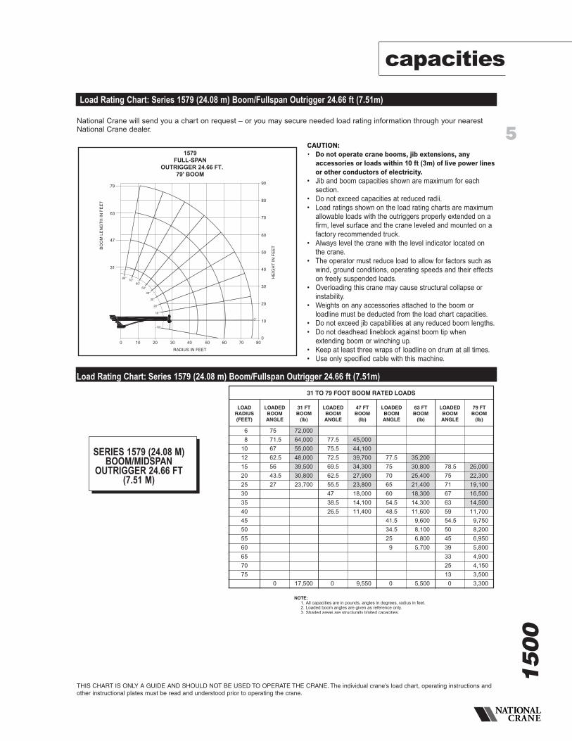
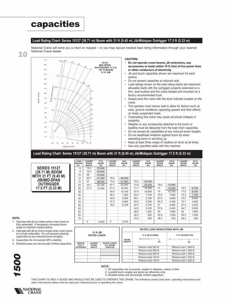
NOTE:1. All capacities are in pounds, angles in degrees, radius in feet.2. Loaded boom angles are given as reference only.3. Shaded areas are structurally limited capacities.
68
10121520253035404550556065707580859095
100
72,00064,00055,00048,00039,50030,50023,000
16,500
75.771.667.563.356.64427.3
0
78.676.473.167.561.555.248.340.531.118.7
0
42,00037,00032,00025,50021,00018,00014,30011,400
9,3007,700
6,800
79.275.471.667.763.759.554.950.345.239.5332512.7
0
26,00021,00017,50015,20013,40011,6009,5008,0006,5005,3004,4003,6003,000
2,700
79.676.87471.168.165.26258.65551.347.443.238.733.727.920.57.2 0
15,00013,50012,00011,00010,000
9,0008,0006,7005,5004,5503,7503,0502,5002,0501,6001,250
900850
103 ftBOOM
LOADEDBOOMANGLE
79 ftBOOM
LOADEDBOOMANGLE
55 ftBOOM
LOADEDBOOMANGLE
LOADEDBOOMANGLE
LOADRADIUS
(ft) (lb) (lb) (lb) (lb)
31 ftBOOM
Reduce load 2,300 lbReduce load 2,000 lbReduce load 1,900 lbReduce load 1,800 lb
31-55 ft JIB ERECTEDAT 31 ft LENGTH
Reduce load 800 lbReduce load 450 lbReduce load 350 lbReduce load 250 lb
BOOMLENGTH
31 ft55 ft79 ft
103 ft
RATED LOAD REDUCTIONS WITH JIB
31-55 ft JIB STOWED
31 TO 103 ft BOOM RATED LOADS WITHOUT JIB31 ft JIB
RATED LOADSRADIUSFULLY
EXTENDED
LOADEDBOOMANGLE
RATED LOADSALL BOOMLENGTHS
807570656055504540
2437485969788795
102
8,5007,5006,4005,1003,9002,8001,9001,250
750
55 ft JIBRATED LOADS
RADIUSFULLY
EXTENDED
LOADEDBOOMANGLE
RATED LOADSALL BOOMLENGTHS
8075706560555045
294559718394
104113
4,0003,7003,2002,7002,2501,8001,300
800
capacities
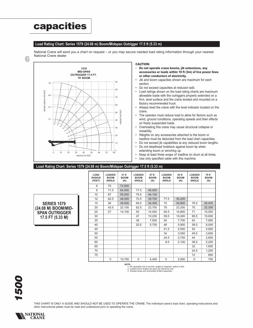
Load Rating Chart: Series 1579 (24.08 m) Boom/Fullspan Outrigger 24.66 ft (7.51m)
Load Rating Chart: Series 1579 (24.08 m) Boom/Fullspan Outrigger 24.66 ft (7.51m)
THIS CHART IS ONLY A GUIDE AND SHOULD NOT BE USED TO OPERATE THE CRANE. The individual crane’s load chart, operating instructions andother instructional plates must be read and understood prior to operating the crane.
National Crane will send you a chart on request – or you may secure needed load rating information through your nearestNational Crane dealer.
1579FULL-SPAN
OUTRIGGER 24.66 FT.79' BOOM
80°70°
60°50°
40°
30°
20°
10°
-10°
0°
0 10 20 30 40 50 60 70 80
RADIUS IN FEET
0
10
20
30
40
90
80
70
60
50
HE
IGH
TIN
FEE
T31
47
63
79
BO
OM
LEN
GTH
INFE
ET
CAUTION:• Do not operate crane booms, jib extensions, any
accessories or loads within 10 ft (3m) of live power linesor other conductors of electricity.
• Jib and boom capacities shown are maximum for eachsection.
• Do not exceed capacities at reduced radii.• Load ratings shown on the load rating charts are maximum
allowable loads with the outriggers properly extended on afirm, level surface and the crane leveled and mounted on afactory recommended truck.
• Always level the crane with the level indicator located onthe crane.
• The operator must reduce load to allow for factors such aswind, ground conditions, operating speeds and their effectson freely suspended loads.
• Overloading this crane may cause structural collapse orinstability.
• Weights on any accessories attached to the boom orloadline must be deducted from the load chart capacities.
• Do not exceed jib capabilities at any reduced boom lengths.• Do not deadhead lineblock against boom tip when
extending boom or winching up.• Keep at least three wraps of loadline on drum at all times.• Use only specified cable with this machine.
SERIES 1579 (24.08 M)BOOM/MIDSPAN
OUTRIGGER 24.66 FT(7.51 M)
31 TO 79 FOOT BOOM RATED LOADS
LOADRADIUS(FEET)
LOADEDBOOMANGLE
31 FTBOOM
(lb)
LOADEDBOOMANGLE
47 FTBOOM
(lb)
LOADEDBOOMANGLE
63 FTBOOM
(lb)
LOADEDBOOMANGLE
79 FTBOOM
(lb)
68101215202530354045505560657075
7571.56762.55643.527
0
72,00064,00055,00048,00039,50030,80023,700
17,500
77.575.572.569.562.555.54738.526.5
0
45,00044,10039,70034,30027,90023,80018,00014,10011,400
9,550
77.57570656054.548.541.534.5259
0
35,20030,80025,40021,40018,30014,30011,6009,6008,1006,8005,700
5,500
78.5757167635954.55045393325130
26,00022,30019,10016,50014,50011,7009,7508,2006,9505,8004,9004,1503,5003,300
6
1500
capacities
THIS CHART IS ONLY A GUIDE AND SHOULD NOT BE USED TO OPERATE THE CRANE. The individual crane’s load chart, operating instructions andother instructional plates must be read and understood prior to operating the crane.
Load Rating Chart: Series 1579 (24.08 m) Boom/Midspan Outrigger 17.5 ft (5.33 m)
Load Rating Chart: Series 1579 (24.08 m) Boom/Midspan Outrigger 17.5 ft (5.33 m)
1579MID-SPAN
OUTRIGGER 17.5 FT.79' BOOM
80°70°
60°50°
40°
30°
20°
10°
-10°
0°
0 10 20 30 40 50 60 70 80
RADIUS IN FEET
0
10
20
30
40
90
80
70
60
50
HE
IGH
TIN
FEE
T31
47
63
79
BO
OM
LEN
GTH
INFE
ET
National Crane will send you a chart on request – or you may secure needed load rating information through your nearestNational Crane dealer.
CAUTION:• Do not operate crane booms, jib extensions, any
accessories or loads within 10 ft (3m) of live power linesor other conductors of electricity.
• Jib and boom capacities shown are maximum for eachsection.
• Do not exceed capacities at reduced radii.• Load ratings shown on the load rating charts are maximum
allowable loads with the outriggers properly extended on afirm, level surface and the crane leveled and mounted on afactory recommended truck.
• Always level the crane with the level indicator located on thecrane.
• The operator must reduce load to allow for factors such aswind, ground conditions, operating speeds and their effectson freely suspended loads.
• Overloading this crane may cause structural collapse orinstability.
• Weights on any accessories attached to the boom orloadline must be deducted from the load chart capacities.
• Do not exceed jib capabilities at any reduced boom lengths.• Do not deadhead lineblock against boom tip when
extending boom or winching up.• Keep at least three wraps of loadline on drum at all times.• Use only specified cable with this machine.
SERIES 1579 (24.08 M) BOOM/MID-SPAN OUTRIGGER
17.5 FT (5.33 M)
NOTE:1. All capacities are in pounds, angles in degrees, radius in feet.2. Loaded boom angles are given as reference only.3. Shaded areas are structurally limited capacities.
68
1012152025303540455055606570
72,00064,00055,00048,00039,50021,30013,300
10,100
75.771.667.563.356.64427.4
0
78.676.473.167.361.154.748.240.531.318.1
0
42,00037,00032,00022,00014,000
9,7007,1005,1503,8002,750
2,300
79.275.471.367.263.258.954.449.644.538.832.324.2
26,00021,00014,1009,8007,2005,3504,0002,9502,1501,450
950475
79.676.873.670.667.464.260.957.55450.446.5
15,00013,500
9,8007,2005,4004,0003,0002,1501,5001,000
550
103 ftBOOM
LOADEDBOOMANGLE
79 ftBOOM
LOADEDBOOMANGLE
55 ftBOOM
LOADEDBOOMANGLE
LOADEDBOOMANGLE
LOADRADIUS
(ft) (lb) (lb) (lb) (lb)
31 ftBOOM
31 TO 103 ft BOOM RATED LOADS WITHOUT JIB31 ft JIB
RATED LOADSRADIUSFULLY
EXTENDED
LOADEDBOOMANGLE
RATED LOADSALL BOOMLENGTHS
8075706560
2436465666
8,5006,9003,7502,000
850
55 ft JIBRATED LOADS
RADIUSFULLY
EXTENDED
LOADEDBOOMANGLE
RATED LOADSALL BOOMLENGTHS
80757065
31465869
4,0003,7002,4001,250
Reduce load 2,300 lbReduce load 2,000 lbReduce load 1,900 lbReduce load 1,800 lb
31-55 ft JIB ERECTEDAT 31 ft LENGTH
Reduce load 800 lbReduce load 450 lbReduce load 350 lbReduce load 250 lb
BOOMLENGTH
31 ft55 ft79 ft
103 ft
RATED LOAD REDUCTIONS WITH JIB
31-55 ft JIB STOWED
LOADRADIUS(FEET)
LOADEDBOOMANGLE
31 ftBOOM
(lb)
LOADEDBOOMANGLE
47 ftBOOM
(lb)
LOADEDBOOMANGLE
63 ftBOOM
(lb)
LOADEDBOOMANGLE
79 ftBOOM
(lb)
68101215202530354045505560657075
7571.56762.55643.527
0
72,00064,00055,00048,00039,50022,10014,100
10,700
77.575.572.569.562.555473825.5
0
45,00044,10039,70034,30022,70014,50010,2007,5005,700
4,450
77.5757064.559.5544841.53424.58.5
0
35,20030,80023,20014,80010,4007,7005,9004,5503,5502,7502,100
2,000
78.5757166.56358.55449.54438.53224.5120
26,00022,30015,00010,6007,8506,0004,6503,6502,8502,2001,6501,200800700
7
1500
NOTE:1. All capacities are in pounds, angles in degrees, radius in feet.2. Loaded boom angles are given as reference only.3. Shaded areas are structurally limited capacities.
68
10121520253035404550556065707580859095
100
72,00064,00055,00048,00039,50030,50023,000
16,500
75.771.667.563.356.64427.3
0
78.676.473.167.561.555.248.340.531.118.7
0
42,00037,00032,00025,50021,00018,00014,30011,400
9,3007,700
6,800
79.275.471.667.763.759.554.950.345.239.5332512.7
0
26,00021,00017,50015,20013,40011,6009,5008,0006,5005,3004,4003,6003,000
2,700
79.676.87471.168.165.26258.65551.347.443.238.733.727.920.57.2 0
15,00013,50012,00011,00010,000
9,0008,0006,7005,5004,5503,7503,0502,5002,0501,6001,250
900850
103 ftBOOM
LOADEDBOOMANGLE
79 ftBOOM
LOADEDBOOMANGLE
55 ftBOOM
LOADEDBOOMANGLE
LOADEDBOOMANGLE
LOADRADIUS
(ft) (lb) (lb) (lb) (lb)
31 ftBOOM
Reduce load 2,300 lbReduce load 2,000 lbReduce load 1,900 lbReduce load 1,800 lb
31-55 ft JIB ERECTEDAT 31 ft LENGTH
Reduce load 800 lbReduce load 450 lbReduce load 350 lbReduce load 250 lb
BOOMLENGTH
31 ft55 ft79 ft
103 ft
RATED LOAD REDUCTIONS WITH JIB
31-55 ft JIB STOWED
31 TO 103 ft BOOM RATED LOADS WITHOUT JIB31 ft JIB
RATED LOADSRADIUSFULLY
EXTENDED
LOADEDBOOMANGLE
RATED LOADSALL BOOMLENGTHS
807570656055504540
2437485969788795
102
8,5007,5006,4005,1003,9002,8001,9001,250
750
55 ft JIBRATED LOADS
RADIUSFULLY
EXTENDED
LOADEDBOOMANGLE
RATED LOADSALL BOOMLENGTHS
8075706560555045
294559718394
104113
4,0003,7003,2002,7002,2501,8001,300
800
capacities
Load Rating Chart: Series 15103 (16.76 m) Boom with 31-55 ft (9.45-16.76 m) Jib/Fullspan Outrigger 24.66 ft (7.51 m)
Load Rating Chart: Series 15103 (16.76 m) Boom with 31-55 ft (9.45-16.76 m) Jib/Fullspan Outrigger 24.66 ft (7.51 m)
THIS CHART IS ONLY A GUIDE AND SHOULD NOT BE USED TO OPERATE THE CRANE. The individual crane’s load chart, operating instructions andother instructional plates must be read and understood prior to operating the crane.
National Crane will send you a chart on request – or you may secure needed load rating information through your nearestNational Crane dealer.
170
160
150
140
130
120
110
100
90
80
70
60
50
40
30
20
10
C/L 10 20 30 40 50 60 70 80 90 100
158
103
80O
75O
55O
60O
65O
70O
50O
45O
40O
35O
30O
25O
20O
10O
15O
5O
OPERATING RADIUS FROMC/L ROTATION IN FEET
WITH UNLOADED BOOM
HO
OK
ELE
VATI
ON
INFE
ET
15103FULL-SPAN
OUTRIGGER 24.66 FT.103 ft BOOM31-55 ft JIB
0O
STABILITYLIMIT LINEWITH400 lbBLOCK
38O
STRUCTURAL LIMITLINE WITH 31 ft JIBDEPLOYED
-10O
134
79
BOO
MLE
NG
THIN
FEET
55
31
43O
STRUCTURAL LIMITLINE WITH 55 ft JIBDEPLOYED
NOTE:1. Operate with jib by radius when main boom is
fully extended. If necessary increase boomangle to maintain loaded radius.
2. Operate with jib by boom angle when main boomis not fully extended. Do not exceed rated jibcapacities at any reduced boom lengths.
3. Capacities do not exceed 85% stability.4. Shaded areas are structurally limited capacities.
0
120
100
80
60
0
40
HE
IGH
TIN
FE
ET
OTE NDJ TO
T SA
140
7
160
SWITCHPOSITION OPERATING MODE
LMI OPERATING CODE SWITCH
01 MAIN BOOM - NO JIB STOWED
02 MAIN BOOM - JIB STOWED
03 25 FT TELE JIB
04 44 FT TELE JIB
11 MAN BASKET ON MAIN BOOM
1
CAUTION:• Do not operate crane booms, jib extensions, any
accessories or loads within 10 ft (3m) of live power linesor other conductors of electricity.
• Jib and boom capacities shown are maximum for eachsection.
• Do not exceed capacities at reduced radii.• Load ratings shown on the load rating charts are maximum
allowable loads with the outriggers properly extended on afirm, level surface and the crane leveled and mounted on afactory recommended truck.
• Always level the crane with the level indicator located onthe crane.
• The operator must reduce load to allow for factors such aswind, ground conditions, operating speeds and their effectson freely suspended loads.
• Overloading this crane may cause structural collapse orinstability.
• Weights on any accessories attached to the boom orloadline must be deducted from the load chart capacities.
• Do not exceed jib capabilities at any reduced boom lengths.• Do not deadhead lineblock against boom tip when
extending boom or winching up.• Keep at least three wraps of loadline on drum at all times.• Use only specified cable with this machine.
SERIES 15103 (24.08 M)BOOM WITH 31-55 FT
(9.45-16.76 M)JIB/FULLSPAN OUTRIGGER
24.66 FT (7.51 M)
8
1500
capacities
THIS CHART IS ONLY A GUIDE AND SHOULD NOT BE USED TO OPERATE THE CRANE. The individual crane’s load chart, operating instructions andother instructional plates must be read and understood prior to operating the crane.
Load Rating Chart: Series 15103 (16.76 m) Boom with 31-55 ft (9.45-16.76 m) Jib/Midspan Outrigger 17.5 ft (5.33 m)
Load Rating Chart: Series 15103 (16.76 m) Boom with 31-55 ft (9.45-16.76 m) Jib/Midspan Outrigger 17.5 ft (5.33 m)
70605040302010C/L
10
20
30
40
50
31
60
70
80
90
100
110
120
130
140
150
160
170
HO
OK
ELE
VAT
ION
INF
EE
T
103
158
BO
OM
LEN
GT
HIN
FE
ET
75O80O
70O
65O
63O
60O
55O
5O
10O
15O
20O
25O
30O
35O
40O
45O
50O
134
79
55
15103MID-SPAN
OUTRIGGER 17.5 ft103 ft BOOM31-55 ft JIB
STABILITYLIMIT LINEWITH400 lbBLOCK
OPERATING RADIUSFROM C/L ROTATION
IN FEET WITHUNLOADED BOOM
0O
-10O
STRUCTURALLIMIT LINE WITH31 ft JIB DEPLOYED
STRUCTURALLIMIT LINE WITH55 ft JIB DEPLOYED
National Crane will send you a chart on request – or you may secure needed load rating information through your nearestNational Crane dealer.
CAUTION:• Do not operate crane booms, jib extensions, any
accessories or loads within 10 ft (3m) of live power linesor other conductors of electricity.
• Jib and boom capacities shown are maximum for eachsection.
• Do not exceed capacities at reduced radii.• Load ratings shown on the load rating charts are maximum
allowable loads with the outriggers properly extended on afirm, level surface and the crane leveled and mounted on afactory recommended truck.
• Always level the crane with the level indicator located on thecrane.
• The operator must reduce load to allow for factors such aswind, ground conditions, operating speeds and their effectson freely suspended loads.
• Overloading this crane may cause structural collapse orinstability.
• Weights on any accessories attached to the boom orloadline must be deducted from the load chart capacities.
• Do not exceed jib capabilities at any reduced boom lengths.• Do not deadhead lineblock against boom tip when
extending boom or winching up.• Keep at least three wraps of loadline on drum at all times.• Use only specified cable with this machine.
SERIES 15103 (24.08 M)BOOM WITH 31-55 FT(9.45-16.76 M) JIB/MID-
SPAN OUTRIGGER 17.5 FT (5.33 M)
NOTE:1. All capacities are in pounds, angles in degrees, radius in feet.2. Loaded boom angles are given as reference only.3. Shaded areas are structurally limited capacities.
68
1012152025303540455055606570
72,00064,00055,00048,00039,50021,30013,300
10,100
75.771.667.563.356.64427.4
0
78.676.473.167.361.154.748.240.531.318.1
0
42,00037,00032,00022,00014,000
9,7007,1005,1503,8002,750
2,300
79.275.471.367.263.258.954.449.644.538.832.324.2
26,00021,00014,1009,8007,2005,3504,0002,9502,1501,450
950475
79.676.873.670.667.464.260.957.55450.446.5
15,00013,500
9,8007,2005,4004,0003,0002,1501,5001,000
550
103 ftBOOM
LOADEDBOOMANGLE
79 ftBOOM
LOADEDBOOMANGLE
55 ftBOOM
LOADEDBOOMANGLE
LOADEDBOOMANGLE
LOADRADIUS
(ft) (lb) (lb) (lb) (lb)
31 ftBOOM
31 TO 103 ft BOOM RATED LOADS WITHOUT JIB31 ft JIB
RATED LOADSRADIUSFULLY
EXTENDED
LOADEDBOOMANGLE
RATED LOADSALL BOOMLENGTHS
8075706560
2436465666
8,5006,9003,7502,000
850
55 ft JIBRATED LOADS
RADIUSFULLY
EXTENDED
LOADEDBOOMANGLE
RATED LOADSALL BOOMLENGTHS
80757065
31465869
4,0003,7002,4001,250
Reduce load 2,300 lbReduce load 2,000 lbReduce load 1,900 lbReduce load 1,800 lb
31-55 ft JIB ERECTEDAT 31 ft LENGTH
Reduce load 800 lbReduce load 450 lbReduce load 350 lbReduce load 250 lb
BOOMLENGTH
31 ft55 ft79 ft
103 ft
RATED LOAD REDUCTIONS WITH JIB
31-55 ft JIB STOWED
NOTE:1. Operate with jib by radius when main boom is
fully extended. If necessary increase boomangle to maintain loaded radius.
2. Operate with jib by boom angle when main boomis not fully extended. Do not exceed rated jibcapacities at any reduced boom lengths.
3. Capacities do not exceed 85% stability.4. Shaded areas are structurally limited capacities.
0
0
0
HE
IGH
TIN
FE
ET
0
0
SWITCHPOSITION OPERATING MODE
LMI OPERATING CODE SWITCH
01 MAIN BOOM - NO JIB STOWED
02 MAIN BOOM - JIB STOWED
03 25 FT TELE JIB
04 44 FT TELE JIB
11 MAN BASKET ON MAIN BOOM
12 MAN BASKET ON 25 FT TELE JIB
13 MAN BASKET ON 44 FT TELE JIB
NOTE:1. All capacities are in pounds, angles in degrees, radius in feet.2. Loaded boom angles are given as reference only.3. Shaded areas are structurally limited capacities.
68
10121520253035404550556065707580859095
100105
72,00063,00054,00047,00038,50029,50022,000
15,500
76.472.26863.75744.327.1
0
76.873.567.861.855.548.640.731.318.9
0
36,00031,00024,60020,50017,40014,00011,000
9,0007,400
6,300
79.575.871.96863.959.755.250.645.439.633.125.112.7
0
25,00020,50017,00014,70012,90011,3009,4007,8006,5005,3004,3003,5002,850
2,600
79.67774.271.368.465.462.258.955.351.547.643.438.833.827.920.57.3
0
14,00013,00011,70010,6009,5008,4007,6006,6005,5004,5003,7003,0502,4001,9001,5001,100
800
750
79.577.575.373.170.868.565.963.360.657.85551.948.745.441.938.134
8,7008,2007,7007,2006,7006,2005,4004,8004,2003,7003,1002,5502,0501,6001,200
850550
127 ftBOOM
LOADEDBOOMANGLE
103 ftBOOM
LOADEDBOOMANGLE
79 ftBOOM
LOADEDBOOMANGLE
55 ftBOOM
LOADEDBOOMANGLE
LOADEDBOOMANGLE
LOADRADIUS
(ft)
31 ftBOOM
(lb) (lb) (lb) (lb) (lb)
Reduce load 1,600 lbReduce load 1,400 lbReduce load 1,300 lbReduce load 1,250 lbReduce load 1,200 lb
31 ft JIB RATED LOADS
31 ft JIB ERECTED
Reduce load 500 lbReduce load 300 lbReduce load 200 lbReduce load 150 lbReduce load 100 lb
BOOMLENGTH
31ft55ft79ft
103ft127ft
RATED LOAD REDUCTIONS WITH JIBRADIUSFULLY
EXTENDED
LOADEDBOOMANGLE
RATED LOADSALL BOOMLENGTHS
80757065605550
294458728494
104
3,8003,3002,9002,5002,1501,6001,000
31 ft JIB STOWED
9
1500
capacities
Load Rating Chart: Series 15127 (38.71 m) Boom with 31 ft (9.45 m) Jib/Fullspan Outrigger 24.66 ft (7.51 m)
Load Rating Chart: Series 15127 (38.71 m) Boom with 31 ft (9.45 m) Jib/Fullspan Outrigger 24.66 ft (7.51 m)
THIS CHART IS ONLY A GUIDE AND SHOULD NOT BE USED TO OPERATE THE CRANE. The individual crane’s load chart, operating instructions andother instructional plates must be read and understood prior to operating the crane.
National Crane will send you a chart on request – or you may secure needed load rating information through your nearestNational Crane dealer.
170
160
150
140
130
120
110
100
90
80
70
60
50
40
30
20
10
C/L 10 20 30 40 50 60 70 80 90 100 105
158
103
80O
75O
55O
60O
65O
70O
50O
45O
40O
35O
30O
25O
20O
10O
15O
5O
RADIUS IN FEET
HE
IGH
TIN
FE
ET
15127FULL-SPAN
OUTRIGGER 24.66 FT.127 ft BOOM
31 ft JIB
0O
48O
-10O
127
79
TE
EF
NIH
TG
NEL
MO
OB
55
31
NOTE:1. Operate with jib by radius when main boom is
fully extended. If necessary increase boomangle to maintain loaded radius.
2. Operate with jib by boom angle when main boomis not fully extended. Do not exceed rated jibcapacities at any reduced boom lengths.
3. Capacities do not exceed 85% stability.4. Shaded areas are structurally limited capacities.
0
120
100
80
60
0
40
HE
IGH
TIN
FE
ET
OTE NDJ TO
T SA
140
7
160
SWITCHPOSITION OPERATING MODE
LMI OPERATING CODE SWITCH
01 MAIN BOOM - NO JIB STOWED
02 MAIN BOOM - JIB STOWED
03 25 FT TELE JIB
0
CAUTION:• Do not operate crane booms, jib extensions, any
accessories or loads within 10 ft (3m) of live power linesor other conductors of electricity.
• Jib and boom capacities shown are maximum for eachsection.
• Do not exceed capacities at reduced radii.• Load ratings shown on the load rating charts are maximum
allowable loads with the outriggers properly extended on afirm, level surface and the crane leveled and mounted on afactory recommended truck.
• Always level the crane with the level indicator located onthe crane.
• The operator must reduce load to allow for factors such aswind, ground conditions, operating speeds and their effectson freely suspended loads.
• Overloading this crane may cause structural collapse orinstability.
• Weights on any accessories attached to the boom orloadline must be deducted from the load chart capacities.
• Do not exceed jib capabilities at any reduced boom lengths.• Do not deadhead lineblock against boom tip when
extending boom or winching up.• Keep at least three wraps of loadline on drum at all times.• Use only specified cable with this machine.
SERIES 15127 (38.71 M)BOOM WITH 31 FT
(9.45 M) JIB/FULL-SPANOUTRIGGER 24.66 FT
(7.51 M)
10
1500
capacities
THIS CHART IS ONLY A GUIDE AND SHOULD NOT BE USED TO OPERATE THE CRANE. The individual crane’s load chart, operating instructions andother instructional plates must be read and understood prior to operating the crane.
Load Rating Chart: Series 15127 (38.71 m) Boom with 31 ft (9.45 m) Jib/Midspan Outrigger 17.5 ft (5.33 m)
Load Rating Chart: Series 15127 (38.71 m) Boom with 31 ft (9.45 m) Jib/Midspan Outrigger 17.5 ft (5.33 m)
70 75605040302010C/L
10
20
30
40
50
31
60
70
80
90
100
110
120
130
140
150
160
170
103
158
TE
EFNI
HTG
NEL
MO
OB
75O80O
70O
65O
61O
60O
55O
5O
10O
15O
20O
25O
30O
35O
40O
45O
50O
127
79
55
15127MID-SPAN
OUTRIGGER 17.5 ft127 ft BOOM
31 ft JIB
RADIUS IN FEET
0O
-10O
HE
IGH
TIN
FE
ET
National Crane will send you a chart on request – or you may secure needed load rating information through your nearestNational Crane dealer.
CAUTION:• Do not operate crane booms, jib extensions, any
accessories or loads within 10 ft (3m) of live power linesor other conductors of electricity.
• Jib and boom capacities shown are maximum for eachsection.
• Do not exceed capacities at reduced radii.• Load ratings shown on the load rating charts are maximum
allowable loads with the outriggers properly extended on afirm, level surface and the crane leveled and mounted on afactory recommended truck.
• Always level the crane with the level indicator located on thecrane.
• The operator must reduce load to allow for factors such aswind, ground conditions, operating speeds and their effectson freely suspended loads.
• Overloading this crane may cause structural collapse orinstability.
• Weights on any accessories attached to the boom orloadline must be deducted from the load chart capacities.
• Do not exceed jib capabilities at any reduced boom lengths.• Do not deadhead lineblock against boom tip when
extending boom or winching up.• Keep at least three wraps of loadline on drum at all times.• Use only specified cable with this machine.
SERIES 15127 (38.71 M) BOOM
WITH 31 FT (9.45 M)JIB/MID-SPANOUTRIGGER
17.5 FT (5.33 M)
68
1012152025303540455055606570
72,00063,00054,00047,00038,50022,10013,400
9,400
76.472.26863.75744.127.4
0
76.873.567.761.454.948.440.631.318.2
0
36,00031,00023,50018,40010,100
7,3005,2003,8002,700
2,200
79.575.871.767.463.459.154.549.744.538.832.224.2
25,00020,50015,30010,6007,7005,7004,2003,1002,2001,500
850400
79.6777470.967.664.36157.65450.346.4
14,00013,00010,7007,9005,9004,4003,3002,4001,6501,050
550
79.577.575.372.770.167.464.76259.356.4
8,7008,2007,7006,0004,6003,4002,5001,8001,200
650
127 ftBOOM
LOADEDBOOMANGLE
103 ftBOOM
LOADEDBOOMANGLE
79 ftBOOM
LOADEDBOOMANGLE
55 ftBOOM
LOADEDBOOMANGLE
LOADEDBOOMANGLE
LOADRADIUS
(ft)
31 ftBOOM
(lb) (lb) (lb) (lb) (lb)
NOTE:1. All capacities are in pounds, angles in degrees, radius in feet.2. Loaded boom angles are given as reference only.3. Shaded areas are structurally limited capacities.
Reduce load 1,600 lbReduce load 1,400 lbReduce load 1,300 lbReduce load 1,250 lbReduce load 1,200 lb
31 ft JIB ERECTED
Reduce load 500 lbReduce load 300 lbReduce load 200 lbReduce load 150 lbReduce load 100 lb
BOOMLENGTH
3 1 '5 5 '7 9 '
1 0 3 '1 2 7 '
RATED LOAD REDUCTIONS WITH JIB
31 ft JIB STOWED
RADIUSFULLY
EXTENDED
LOADEDBOOMANGLE
RATED LOADSALL BOOMLENGTHS
8 07 57 06 5
2 94 45 66 7
3 , 8 0 03 , 3 0 02 , 0 0 0
6 0 0
31 ft JIBRATED LOADS
NOTE:1. Operate with jib by radius when main boom is
fully extended. If necessary increase boomangle to maintain loaded radius.
2. Operate with jib by boom angle when main boomis not fully extended. Do not exceed rated jibcapacities at any reduced boom lengths.
3. Capacities do not exceed 85% stability.4. Shaded areas are structurally limited capacities.
0
SWITCHPOSITION OPERATING MODE
LMI OPERATING CODE SWITCH
01 MAIN BOOM - NO JIB STOWED
02 MAIN BOOM - JIB STOWED
03 25 FT TELE JIB
04 44 FT TELE JIB
11 MAN BASKET ON MAIN BOOM
12 MAN BASKET ON 25 FT TELE JIB
13 MAN BASKET ON 44 FT TELE JIB
11
1500
accessories
Radio Remote Controls –Eliminate the handling and maintenance concerns that accompany cabled remotes. Operate to a range of about 250 ft (76 m), varying with conditions. • NB4R (R4 functions)
One-Person Basket –Strong but lightweight steel basket with 300 lb (139 kg) capacity, gravity hung • B1-Swith swing lock and full body harness. • 2B1-S (for dual locking baskets)
Heavy-duty Personnel Basket –1,200 lb (544 kg) capacity steel basket with safety loops for four passengers. Gravityleveling 72 x 42 in (183 x 107 cm) platform. Fast attachment and secure locking • BSA-1systems. • BSA-R1 (provides rotation)
Air Conditioning for Crane Cab –(Requires larger truck alternator) Provides excellent crane cab cooling to overcomethe radiant heat from the sun reflection. • A/C
Auxiliary Winch 9,000 lb Line Pull –Second winch redundant to the main, planetary winch with boom tip “rooster sheave” to allow reeving of both winch lines. • 15AW
Winch Drum Rotation Indicator –Winch drum rotation indicator on winch control lever • WDRIor in cab (for use with standard and auxiliary winches). • WDRI-2
Hour Meter –Hour meter in truck cab to record crane operation hours. • HRM
Steel Tool Box Options
Spanish-Language Danger Decals, Control Knobs, and Operators’ Manuals • SDD• SOM
12
1500
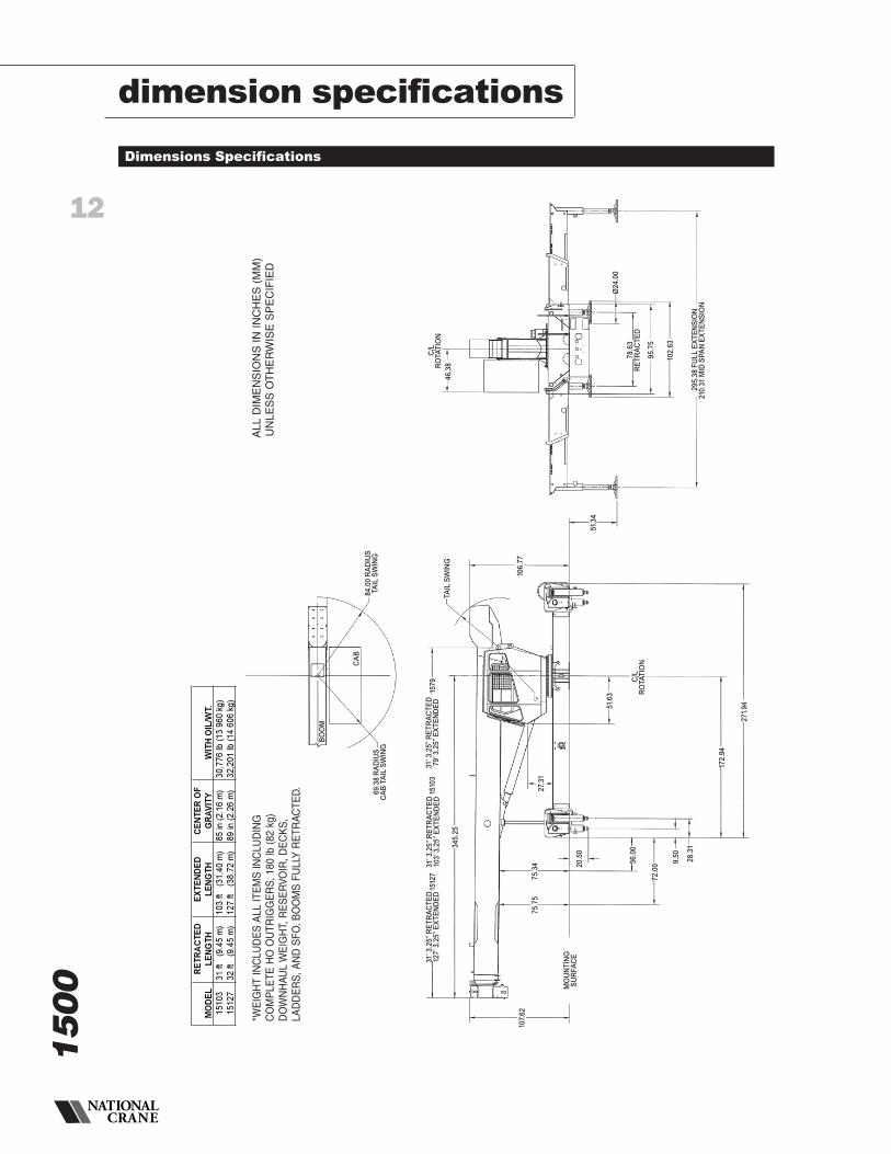
Dimensions Specifications
BO
OM
69
.38
RA
DIU
SC
AB
TA
ILS
WIN
G
CA
B
84
.00
RA
DIU
ST
AIL
SW
ING
C/L
RO
TA
TIO
N
46
.38
Ø2
4.0
0
78
.63
RE
TR
AC
TE
D
95
.75
102
.63
29
5.3
8F
UL
LE
XT
EN
SIO
N21
0.3
1M
IDS
PA
NE
XT
EN
SIO
N
51.3
4
106
.77
TA
ILS
WIN
G
31’3
.25
”R
ET
RA
CT
ED
79
’3.2
5”
EX
TE
ND
ED
157
9
34
5.2
5
1510
315
127
31’3
.25
”R
ET
RA
CT
ED
103
’3.2
5”
EX
TE
ND
ED
31’3
.25
”R
ET
RA
CT
ED
127
’3.2
5”
EX
TE
ND
ED
107.
62
MO
UN
TIN
GS
UR
FA
CE
75
.75
75
.34 20
.50
27.
31
51.6
3
36
.00
72
.00
9.5
0
28
.31
172
.94
271
.94
C/L
RO
TA
TIO
N
ALL
DIM
EN
SIO
NS
ININ
CH
ES
(MM
)U
NLE
SS
OT
HE
RW
ISE
SP
EC
IFIE
D
MO
DE
LR
ETR
AC
TED
LEN
GTH
EX
TEN
DE
DLE
NG
THC
EN
TER
OF
GR
AV
ITY
WIT
HO
IL/W
T.15
103
31ft
(9.4
5m
)10
3ft
(31.
40m
)85
in(2
.16
m)
30,7
76lb
(13
960
kg)
1512
732
ft(9
.45
m)
127
ft(3
8.72
m)
89in
(2.2
6m
)32
,201
lb(1
460
6kg
)
*WE
IGH
TIN
CLU
DE
SA
LLIT
EM
SIN
CLU
DIN
GC
OM
PLE
TEH
OO
UTR
IGG
ER
S,1
80lb
(82
kg)
DO
WN
HAU
LW
EIG
HT,
RE
SE
RVO
IR,D
EC
KS
,LA
DD
ER
S,A
ND
SFO
.BO
OM
SFU
LLY
RE
TRAC
TED
.
dimension specifications

13
notes
1500

14
1500
notes

15
1500
notes
Constant improvement and engineering progressmake it necessary that we reserve the right to makespecification, equipment and price changes withoutnotice. Illustrations shown may include optionalequipment and accessories, and may not include allstandard equipment.
AmericasBrazilAlphavilleTel: +55 11 3103 0200Fax: +55 11 4688 2013
MexicoMonterreyTel: +52 81 8124 0128Fax: +52 81 8124 0129
Europe, Middle East, AfricaAlgeriaHydraTel: +21 3 21 48 1173Fax: +21 3 21 48 1454
Czech RepublicNetvoriceTel: +420 317 78 9313Fax: +420 317 78 9314
FranceBaudemontTel: +33 385 28 2589Fax: +33 385 28 0430
CergyTel: +33 130 31 3150Fax: +33 130 38 6085
DecinesTel: +33 472 81 5000Fax: +33 472 81 5010
GermanyLangenfeldTel: +49 21 73 8909-0Fax: +49 21 73 8909 30
HungaryBudapestTel: +36 13 39 8622Fax: +36 13 39 8622
ItalyParabiagoTel: +390 331 49 3311Fax: +390 331 49 3330
NetherlandsBredaTel: +31 76 578 3999 Fax: +31 76 578 3978
PolandWarsawTel: +48 22 843 3824Fax: +48 22 843 3471
PortugalAlfenaTel: +351 229 69 8840Fax: +351 229 69 8848
LisbonTel: +351 212 109 340Fax: +351 212 109 349
RussiaMoscowTel: +7 495 641 2359Fax: +7 495 641 2358
U.A.E.DubaiTel: +971 4 3381 861Fax: +971 4 3382 343
U. K.MiddlesexTel: +44 1 895 43 0053Fax: +44 1 895 45 9500
SunderlandTel: +44 191 522 2000Fax: +44 191 522 2052
Asia – PacificAustraliaMelbourneTel: +61 3 9 336 1300Fax: +61 3 9 336 1322
SydneyTel: +61 2 9 896 4433Fax: +61 2 9 896 3122
ChinaBeijingTel: +86 10 58674761Fax: +86 10 58674760
Xi’anTel: +86 29 87891465Fax: +86 29 87884504
KoreaSeoulTel: +82 2 3439 0400Fax: +82 2 3439 0405
PhilippinesMakati CityTel: +63 2 844 9437Fax: +63 2 844 4712
Factories
BrazilAlphaville
ChinaZhangjiagang
FranceCharlieuLa ClayetteMoulins
GermanyWilhelmshaven
IndiaCalcuttaPune
ItalyNiella Tanaro
PortugalBaltarFânzeres
SlovakiaSaris
U.S.A.ManitowocPort WashingtonShady Grove
Regional Offices
AmericasManitowoc, Wisconsin, USATel: +1 920 684 6621Fax: +1 920 683 6278
Shady Grove, Pennsylvania, USATel: +1 717 597 8121Fax: +1 717 597 4062
Europe, Middle East, AfricaEcully, FranceTel: +33 472 18 2020Fax: +33 472 18 2000
Asia – PacificShanghai, ChinaTel: +86 21 51113579Fax: +86 21 51113578
SingaporeTel: +65 6264 1188Fax: +65 6862 4142
Regional Headquarters
©2007 MANITOWOCPrinted in USA Form No. 1500 Part No. 1500 / 0108 / 2M
www.manitowoccranegroup.com
Custom Service Crane, Inc.www.CustomServiceCrane.com | t: 217-897-1700 | [email protected]