Embed Size (px)
Citation preview
www.ceag.de EMERGENCY LIGHTING Catalogue 1707 203
2
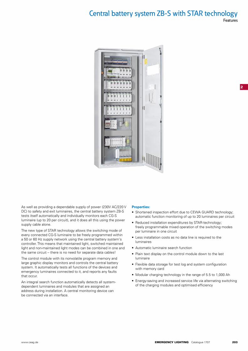
Central battery system ZB-S with STAR technologyFeatures
Properties:• Shortened inspection effort due to CEWA GUARD technology;
automatic function monitoring of up to 20 luminaires per circuit
• Reduced installation expenditures by STAR-technology; freely programmable mixed operation of the switching modes per luminaire in one circuit
• Less installation costs as no data line is required to the luminaires
• Automatic luminaire search function
• Plain text display on the control module down to the last luminaire
• Flexible data storage for test log and system configuration with memory card
• Modular charging technology in the range of 5.5 to 1,000 Ah
• Energy-saving and increased service life via alternating switching of the charging modules and optimised efficiency
As well as providing a dependable supply of power (230V AC/220 V DC) to safety and exit luminaires, the central battery system ZB-S tests itself automatically and individually monitors each CG-S luminaire (up to 20 per circuit), and it does all this using the power supply cable alone.
The new type of STAR technology allows the switching mode of every connected CG-S luminaire to be freely programmed within a 50 or 60 Hz supply network using the central battery system‘s controller. This means that maintained light, switched maintained light and non-maintained light modes can be combined in one and the same circuit – there is no need for separate data cables!
The control module with its nonvolatile program memory and large graphic display monitors and controls the central battery system. It automatically tests all functions of the devices and emergency luminaires connected to it, and reports any faults that occur.
An integral search function automatically detects all system- dependent luminaires and modules that are assigned an address during installation. A central monitoring device can be connected via an interface.
204 EMERGENCY LIGHTING Catalogue 1707 www.ceag.de
2
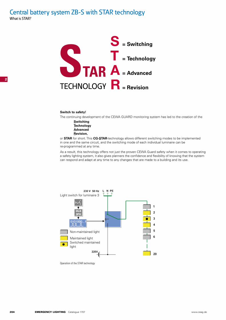
Operation of the STAR technology
Light switch for luminaire 3
Non-maintained light
Maintained lightSwitched maintainedlight
S = Switching
T = Technology
A = Advanced
R = Revision
Switch to safety!The continuing development of the CEWA GUARD monitoring system has led to the creation of the Switching Technology Advanced Revision,or STAR for short. This CG-STAR-technology allows different switching modes to be implemented in one and the same circuit, and the switching mode of each individual luminaire can be re-programmed at any time.
As a result, this technology offers not just the proven CEWA Guard safety when it comes to operating a safety lighting system, it also gives planners the confidence and flexibility of knowing that the system can respond and adapt at any time to any changes that are made to a building and its use.
Central battery system ZB-S with STAR technologyWhat is STAR?
www.ceag.de EMERGENCY LIGHTING Catalogue 1707 205
2
DS
DSBS
BS
DLS
DLS
DS
DSBS
BS
DLS
DLS
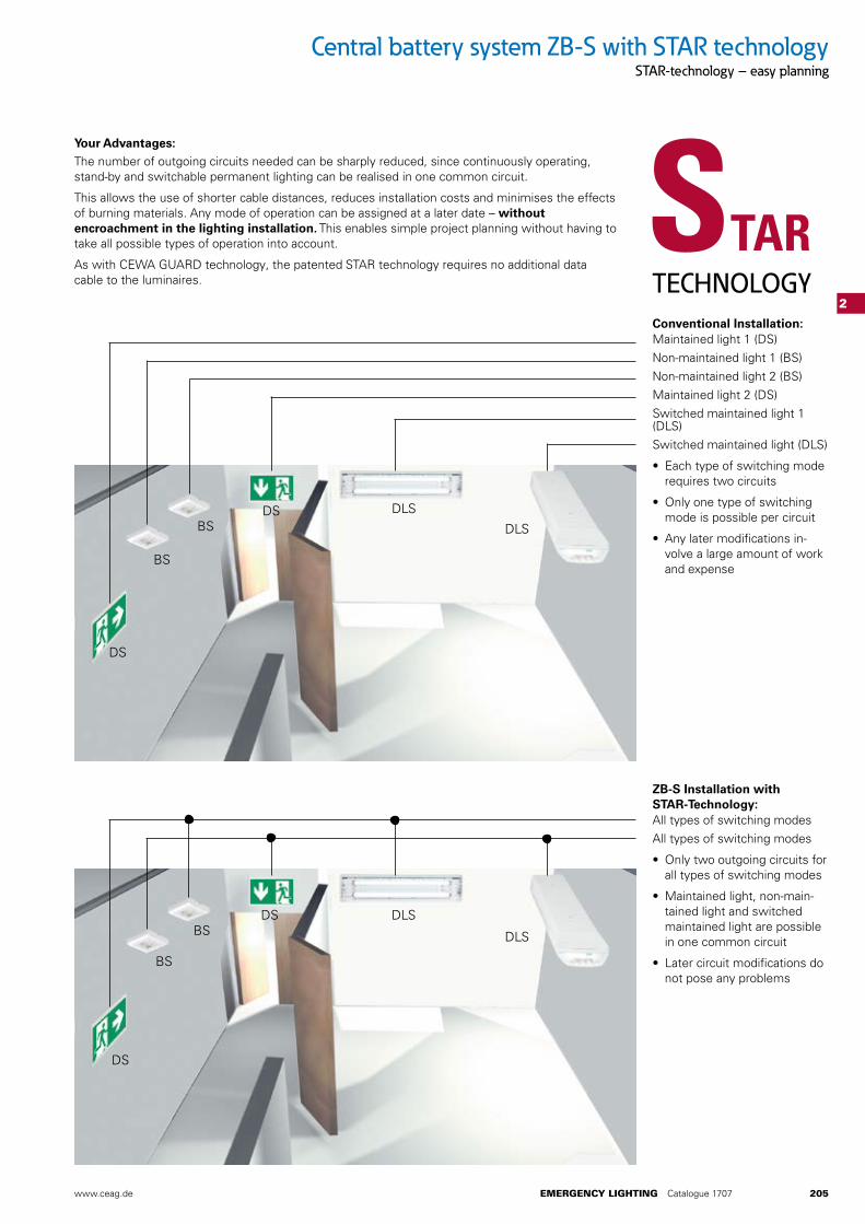
Your Advantages:The number of outgoing circuits needed can be sharply reduced, since continuously operating, stand-by and switchable permanent lighting can be realised in one common circuit.
This allows the use of shorter cable distances, reduces installation costs and minimises the effects of burning materials. Any mode of operation can be assigned at a later date – without encroachment in the lighting installation. This enables simple project planning without having to take all possible types of operation into account.
As with CEWA GUARD technology, the patented STAR technology requires no additional data cable to the luminaires.
Conventional Installation:Maintained light 1 (DS)Non-maintained light 1 (BS)Non-maintained light 2 (BS)Maintained light 2 (DS)Switched maintained light 1 (DLS)Switched maintained light (DLS)
• Each type of switching mode requires two circuits
• Only one type of switching mode is possible per circuit
• Any later modifications in-volve a large amount of work and expense
ZB-S Installation with STAR-Technology:All types of switching modesAll types of switching modes
• Only two outgoing circuits for all types of switching modes
• Maintained light, non-main-tained light and switched maintained light are possible in one common circuit
• Later circuit modifications do not pose any problems
Central battery system ZB-S with STAR technologySTAR-technology – easy planning
206 EMERGENCY LIGHTING Catalogue 1707 www.ceag.de
2
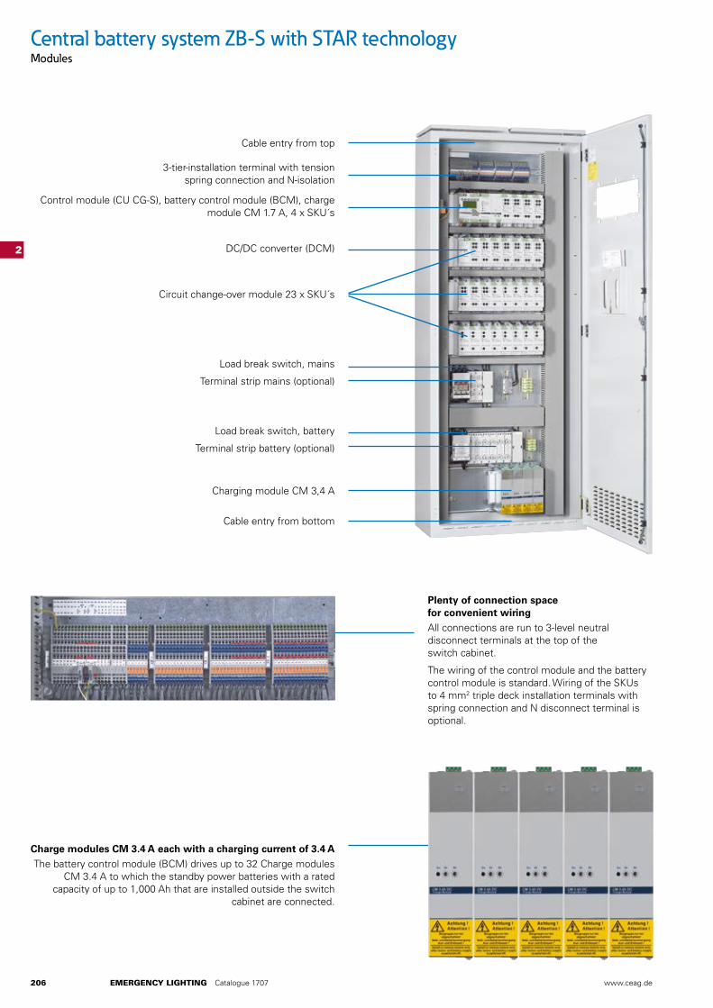
Plenty of connection space for convenient wiringAll connections are run to 3-level neutral disconnect terminals at the top of the switch cabinet.
The wiring of the control module and the battery control module is standard. Wiring of the SKUs to 4 mm2 triple deck installation terminals with spring connection and N disconnect terminal is optional.
Charge modules CM 3.4 A each with a charging current of 3.4 AThe battery control module (BCM) drives up to 32 Charge modules
CM 3.4 A to which the standby power batteries with a rated capacity of up to 1,000 Ah that are installed outside the switch
cabinet are connected.
Cable entry from top
3-tier-installation terminal with tension spring connection and N-isolation
Control module (CU CG-S), battery control module (BCM), charge module CM 1.7 A, 4 x SKU´s
DC/DC converter (DCM)
Circuit change-over module 23 x SKU´s
Load break switch, mains
Terminal strip mains (optional)
Load break switch, battery
Terminal strip battery (optional)
Charging module CM 3,4 A
Cable entry from bottom
Central battery system ZB-S with STAR technologyModules
www.ceag.de EMERGENCY LIGHTING Catalogue 1707 207
2
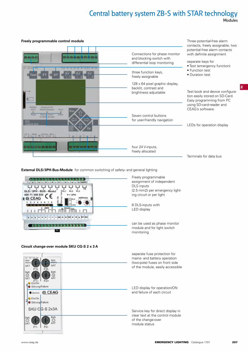
Freely programmable assignment of independent DLS inputs (2.5 mm2) per emergency light-ing circuit or per light
8 DLS-inputs with LED display
can be used as phase monitor module and for light switch monitoring
Terminals for data bus
four 24 V-inputs, freely allocated
Seven control buttons for user-friendly navigation
three function keys, freely assignable
Connections for phase monitor and blocking switch with differential loop monitoring
128 x 64 pixel graphic display, backlit, contrast and brightness adjustable Test book and device configura-
tion easily stored on SD-Card. Easy programming from PC using SD-card-reader and CEAG’s software.
separate keys for • Test (emergency function) • Function test • Duration test
Three potential-free alarm contacts, freely assignable, two potential-free alarm contacts with definite assignment
LEDs for operation display
separate fuse protection for mains- and battery operation (two-pole) fuses on front side of the module, easily accessible
LED display for operation/ON and failure of each circuit
Service key for direct display in clear text at the control module of the change-over module status
External DLS/3PH-Bus-Module for common switching of safety- and general lighting
Freely programmable control module
Circuit change-over module SKU CG-S 2 x 3 A
Central battery system ZB-S with STAR technologyModules
208 EMERGENCY LIGHTING Catalogue 1707 www.ceag.de
2 31 20
2 31 20
2 31 20
2 31 20
2
US-S/ SOU1
US-S/ SOU1
US-S/ SOU1
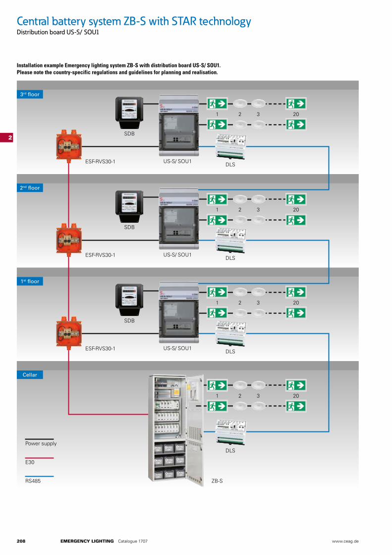
Cellar
1st floor
2nd floor
3rd floor
Power supply
E30
RS485
ESF-RVS30-1
ESF-RVS30-1
ESF-RVS30-1
SDB
SDB
SDB
DLS
DLS
DLS
DLS
ZB-S
Central battery system ZB-S with STAR technologyDistribution board US-S/ SOU1
Installation example Emergency lighting system ZB-S with distribution board US-S/ SOU1. Please note the country-specific regulations and guidelines for planning and realisation.
www.ceag.de EMERGENCY LIGHTING Catalogue 1707 209
2
Switching over unit SOU CG-S 2 x 4 A
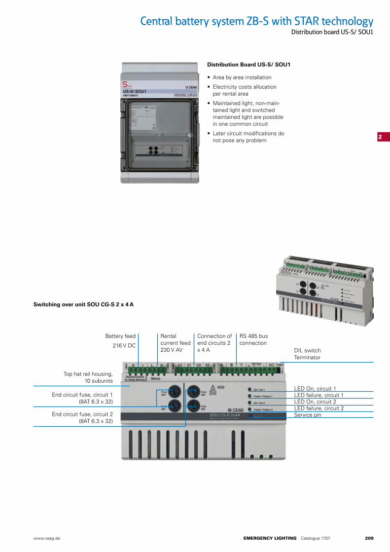
Distribution Board US-S/ SOU1
LED On, circuit 1 LED failure, circuit 1 LED On, circuit 2 LED failure, circuit 2 Service pin
Top hat rail housing, 10 subunits
Battery feed
216 V DC
Rental current feed 230 V AV
Connection of end circuits 2 x 4 A
• Area by area installation
• Electricity costs allocation per rental area
• Maintained light, non-main-tained light and switched maintained light are possible in one common circuit
• Later circuit modifications do not pose any problem
RS 485 bus connection
DIL switch Terminator
End circuit fuse, circuit 1 (8AT 6.3 x 32)
End circuit fuse, circuit 2 (8AT 6.3 x 32)
Central battery system ZB-S with STAR technologyDistribution board US-S/ SOU1
236 EMERGENCY LIGHTING Catalogue 1707 www.ceag.de
Central battery system ZB-S with STAR technologyOrdering details
2
Ordering details Type Scope of supply Order No.
Central battery system ZB-S/26 Central battery system type ZB-S/26 incl. CU CG-S, BCM and DC/DC.2, 26 free module slots*1
40071362905
Central battery system ZB-S/18 Central battery system type ZB-S/18 incl. CU CG-S, BCM and DC/DC.2, 18 free module slots*1
40071362906
Central battery system ZB-S/LAD Central battery system type ZB-S/LAD incl. CU CG-S, BCM and DC/DC.2, (2 free module slots possible)
40071347099
Central battery system ZB-S/10 C Central battery system type ZB-S/10 C, incl. CU CG-S, BCM and DC/DC.2, 10 free module slots*1
40071362900
Central battery system ZB-S/26 C6 Central battery system type ZB-S/26 C6 incl. CU CG-S, BCM and DC/DC.2, 26 free module slots*1
40071689064
Central battery system ZB-S/18 C6 Central battery system type ZB-S/18 C6 incl. CU CG-S, BCM and DC/DC.2, 18 free module slots*1
40071362904
Central battery system ZB-S/10 C6 Central battery system type ZB-S/10 C6 incl. CU CG-S, BCM and DC/DC.2, 10 free module slots*1
40071362903
Central battery system ZB-S/18 C3 Central battery system type ZB-S/18 C3, incl. CU CG-S, BCM and DC/DC.2, 19 free module slots
40071362902
Central battery system ZB-S/10 C3 Central battery system type ZB-S/10 C3, incl. CU CG-S, BCM and DC/DC.2, 11 free module slots
40071362901
Central battery system ZB-S/2 C3 Central battery system type ZB-S/2 C3, incl. CU CG-S, BCM and DC/DC.2, 3 free module slots
40071360201
Substation US-S/36 Substation type US-S/36 incl. CU CG-S and DC/DC.2, 36 free module slots
40071362907
Substation US-S/28 Substation type US-S/28 incl. CU CG-S and DC/DC.2, 28 free module slots
40071362908
Substation US-S/21 Substation type US-S/21 incl. CU CG-S and DC/DC.2, 21 free module slots
40071347088
Substation US-S/13 Substation type US-S/13 incl. CU CG-S and DC/DC.2, 13 free module slots
40071347089
Substation US-S/5 Substation type US-S/5 incl. CU CG-S and DC/DC.2, 5 free module slots
40071347090
Substation US-S/ SOU2 Substation type US-S/ SOU2 incl. 2 x SOU CG-S 2 x 4 A
40071360510
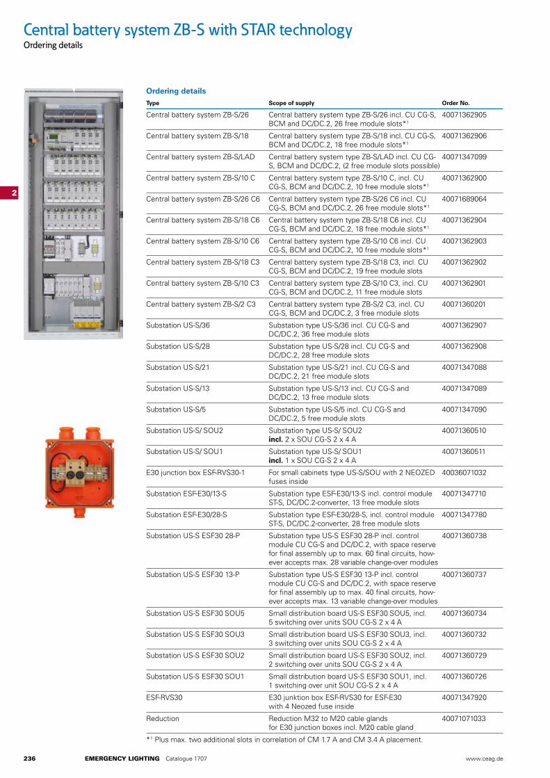
Substation US-S/ SOU1 Substation type US-S/ SOU1 incl. 1 x SOU CG-S 2 x 4 A
40071360511
E30 junction box ESF-RVS30-1 For small cabinets type US-S/SOU with 2 NEOZED fuses inside
40036071032
Substation ESF-E30/13-S Substation type ESF-E30/13-S incl. control module ST-S, DC/DC.2-converter, 13 free module slots
40071347710
Substation ESF-E30/28-S Substation type ESF-E30/28-S, incl. control module ST-S, DC/DC.2-converter, 28 free module slots
40071347780
Substation US-S ESF30 28-P Substation type US-S ESF30 28-P incl. control module CU CG-S and DC/DC.2, with space reserve for final assembly up to max. 60 final circuits, how-ever accepts max. 28 variable change-over modules
40071360738
Substation US-S ESF30 13-P Substation type US-S ESF30 13-P incl. control module CU CG-S and DC/DC.2, with space reserve for final assembly up to max. 40 final circuits, how-ever accepts max. 13 variable change-over modules
40071360737
Substation US-S ESF30 SOU5 Small distribution board US-S ESF30 SOU5, incl. 5 switching over units SOU CG-S 2 x 4 A
40071360734
Substation US-S ESF30 SOU3 Small distribution board US-S ESF30 SOU3, incl. 3 switching over units SOU CG-S 2 x 4 A
40071360732
Substation US-S ESF30 SOU2 Small distribution board US-S ESF30 SOU2, incl. 2 switching over units SOU CG-S 2 x 4 A
40071360729
Substation US-S ESF30 SOU1 Small distribution board US-S ESF30 SOU1, incl. 1 switching over unit SOU CG-S 2 x 4 A
40071360726
ESF-RVS30 E30 junktion box ESF-RVS30 for ESF-E30 with 4 Neozed fuse inside
40071347920
Reduction Reduction M32 to M20 cable glands for E30 junction boxes incl. M20 cable gland
40071071033
*1 Plus max. two additional slots in correlation of CM 1.7 A and CM 3.4 A placement.
www.ceag.de EMERGENCY LIGHTING Catalogue 1707 237
Central battery system ZB-S with STAR technologyOrdering details
2
Ordering details Type Scope of supply Order No.
EBR-S 1800 Electrical Service Room inclusive cabel- and ventilation bulkhead for self assembling. For installation of safety power supply systems with max dimensions (mm) H=1800, W=600, D=300
40036071110
EBR-S-M 1800 Electrical Service Room inclusive cabel- and ventilation bulkhead complete mounted. For installation of safety power supply systems with max dimensions (mm) H=1800, W=600, D=300
40036071111
EBR-S 2050 Electrical Service Room inclusive cabel- and ventilation bulkhead for self assembling. For installation of safety power supply systems with max dimensions (mm) H=2050, W=800, D=600
40036071112
4 pcs. DIN-mounting rail incl. mounting accessories 40071347125
3 pcs. C-section rail incl. mounting accessories 40071347126
Base 200 mm for ZB-S, depth 400 mm 40071361216
Base 100 mm for ZB-S, depth 400 mm 40071361215
Base 200 mm for ZB-S/18C3 and 10C3, depth 330 mm 40071360049
Base 800 x 600 x 200 mm for ZB-S/10C6-18C6 and 26C6 40017361219
3-piece baseplate for ZB-S, depth 400 mm, mouse-proof 40071347124
Cable support rail 40071347123
Metal flange plate undrilled for battery cabinet ZB-S 40071346225
Flange plate for foam rubber for battery cabinet ZB-S 40036070164
Fireproof dowel M10 for E30 substation, Set of = 12 pcs., for installation in concrete walls
40036070298
Optional wall mounting plate for wall mounting for ESF-E30/13-S
40071347726
Door with left hinge for ZB-S/18 and ZB-S/26
40071689081
Door with left hinge for ZB-S/10C3 40071361325
Door with left hinge for ZB-S/10C and ZB-10C6
40071361326
Door with left hinge for battery cabinet
40071689085
238 EMERGENCY LIGHTING Catalogue 1707 www.ceag.de
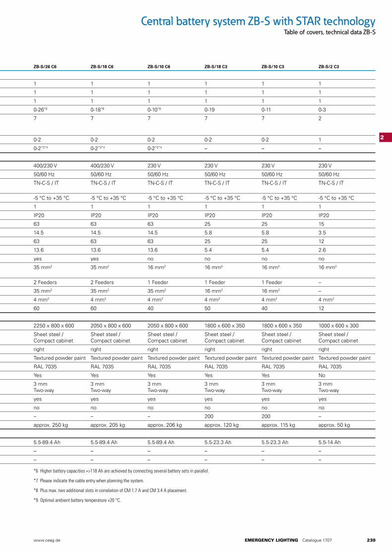
Central battery system ZB-S with STAR technologyTable of covers, technical data ZB-S
2
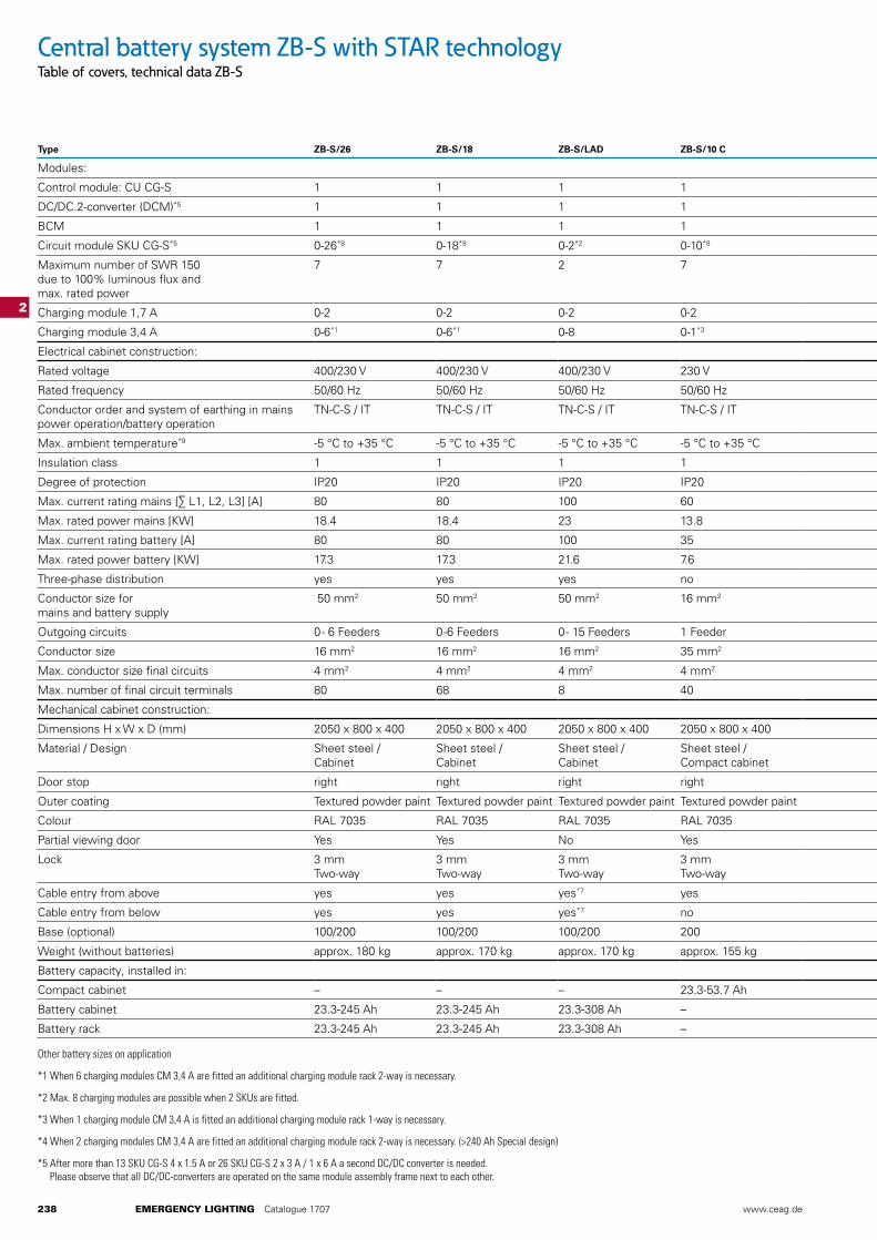
Type ZB-S/26 ZB-S/18 ZB-S/LAD ZB-S/10 C ZB-S/26 C6 ZB-S/18 C6 ZB-S/10 C6 ZB-S/18 C3 ZB-S/10 C3 ZB-S/2 C3
Modules:
Control module: CU CG-S 1 1 1 1 1 1 1 1 1 1
DC/DC.2-converter (DCM)*5 1 1 1 1 1 1 1 1 1 1
BCM 1 1 1 1 1 1 1 1 1 1
Circuit module SKU CG-S*5 0-26*8 0-18*8 0-2*2 0-10*8 0-26*8 0-18*8 0-10*8 0-19 0-11 0-3
Maximum number of SWR 150 due to 100% luminous flux and max. rated power
7 7 2 7 7 7 7 7 7 2
Charging module 1,7 A 0-2 0-2 0-2 0-2 0-2 0-2 0-2 0-2 0-2 1
Charging module 3,4 A 0-6*1 0-6*1 0-8 0-1*3 0-2*3*4 0-2*3*4 0-2*3*4 – – –
Electrical cabinet construction:
Rated voltage 400/230 V 400/230 V 400/230 V 230 V 400/230 V 400/230 V 230 V 230 V 230 V 230 V
Rated frequency 50/60 Hz 50/60 Hz 50/60 Hz 50/60 Hz 50/60 Hz 50/60 Hz 50/60 Hz 50/60 Hz 50/60 Hz 50/60 Hz
Conductor order and system of earthing in mains power operation/battery operation
TN-C-S / IT TN-C-S / IT TN-C-S / IT TN-C-S / IT TN-C-S / IT TN-C-S / IT TN-C-S / IT TN-C-S / IT TN-C-S / IT TN-C-S / IT
Max. ambient temperature*9 -5 °C to +35 °C -5 °C to +35 °C -5 °C to +35 °C -5 °C to +35 °C -5 °C to +35 °C -5 °C to +35 °C -5 °C to +35 °C -5 °C to +35 °C -5 °C to +35 °C -5 °C to +35 °C
Insulation class 1 1 1 1 1 1 1 1 1 1
Degree of protection IP20 IP20 IP20 IP20 IP20 IP20 IP20 IP20 IP20 IP20
Max. current rating mains [∑ L1, L2, L3] [A] 80 80 100 60 63 63 63 25 25 15
Max. rated power mains [KW] 18.4 18.4 23 13.8 14.5 14.5 14.5 5.8 5.8 3.5
Max. current rating battery [A] 80 80 100 35 63 63 63 25 25 12
Max. rated power battery [KW] 17.3 17.3 21.6 7.6 13.6 13.6 13.6 5.4 5.4 2.6
Three-phase distribution yes yes yes no yes yes no no no no
Conductor size for mains and battery supply
50 mm2 50 mm2 50 mm2 16 mm2 35 mm2 35 mm2 16 mm2 16 mm2 16 mm2 16 mm2
Outgoing circuits 0 - 6 Feeders 0 -6 Feeders 0 - 15 Feeders 1 Feeder 2 Feeders 2 Feeders 1 Feeder 1 Feeder 1 Feeder –
Conductor size 16 mm2 16 mm2 16 mm2 35 mm2 35 mm2 35 mm2 35 mm2 16 mm2 16 mm2 –
Max. conductor size final circuits 4 mm2 4 mm2 4 mm2 4 mm2 4 mm2 4 mm2 4 mm2 4 mm2 4 mm2 4 mm2
Max. number of final circuit terminals 80 68 8 40 60 60 40 50 40 12
Mechanical cabinet construction:
Dimensions H x W x D (mm) 2050 x 800 x 400 2050 x 800 x 400 2050 x 800 x 400 2050 x 800 x 400 2250 x 800 x 600 2050 x 800 x 600 2050 x 800 x 600 1800 x 600 x 350 1800 x 600 x 350 1000 x 600 x 300
Material / Design Sheet steel / Cabinet
Sheet steel / Cabinet
Sheet steel / Cabinet
Sheet steel / Compact cabinet
Sheet steel / Compact cabinet
Sheet steel / Compact cabinet
Sheet steel / Compact cabinet
Sheet steel / Compact cabinet
Sheet steel / Compact cabinet
Sheet steel / Compact cabinet
Door stop right right right right right right right right right right
Outer coating Textured powder paint Textured powder paint Textured powder paint Textured powder paint Textured powder paint Textured powder paint Textured powder paint Textured powder paint Textured powder paint Textured powder paint
Colour RAL 7035 RAL 7035 RAL 7035 RAL 7035 RAL 7035 RAL 7035 RAL 7035 RAL 7035 RAL 7035 RAL 7035
Partial viewing door Yes Yes No Yes Yes Yes Yes Yes Yes No
Lock 3 mm Two-way
3 mm Two-way
3 mm Two-way
3 mm Two-way
3 mm Two-way
3 mm Two-way
3 mm Two-way
3 mm Two-way
3 mm Two-way
3 mm Two-way
Cable entry from above yes yes yes*7 yes yes yes yes yes yes yes
Cable entry from below yes yes yes*7 no no no no no no no
Base (optional) 100/200 100/200 100/200 200 – – – 200 200 –
Weight (without batteries) approx. 180 kg approx. 170 kg approx. 170 kg approx. 155 kg approx. 250 kg approx. 205 kg approx. 206 kg approx. 120 kg approx. 115 kg approx. 50 kg
Battery capacity, installed in:
Compact cabinet – – – 23.3-53.7 Ah 5.5-89.4 Ah 5.5-89.4 Ah 5.5-89.4 Ah 5.5-23.3 Ah 5.5-23.3 Ah 5.5-14 Ah
Battery cabinet 23.3-245 Ah 23.3-245 Ah 23.3-308 Ah – – – – – – –
Battery rack 23.3-245 Ah 23.3-245 Ah 23.3-308 Ah – – – – – – –
Other battery sizes on application
*1 When 6 charging modules CM 3,4 A are fitted an additional charging module rack 2-way is necessary.
*2 Max. 8 charging modules are possible when 2 SKUs are fitted.
*3 When 1 charging module CM 3,4 A is fitted an additional charging module rack 1-way is necessary.
*4 When 2 charging modules CM 3,4 A are fitted an additional charging module rack 2-way is necessary. (>240 Ah Special design)
*5 After more than 13 SKU CG-S 4 x 1.5 A or 26 SKU CG-S 2 x 3 A / 1 x 6 A a second DC/DC converter is needed. Please observe that all DC/DC-converters are operated on the same module assembly frame next to each other.
www.ceag.de EMERGENCY LIGHTING Catalogue 1707 239
Central battery system ZB-S with STAR technologyTable of covers, technical data ZB-S
2
Type ZB-S/26 ZB-S/18 ZB-S/LAD ZB-S/10 C ZB-S/26 C6 ZB-S/18 C6 ZB-S/10 C6 ZB-S/18 C3 ZB-S/10 C3 ZB-S/2 C3
Modules:
Control module: CU CG-S 1 1 1 1 1 1 1 1 1 1
DC/DC.2-converter (DCM)*5 1 1 1 1 1 1 1 1 1 1
BCM 1 1 1 1 1 1 1 1 1 1
Circuit module SKU CG-S*5 0-26*8 0-18*8 0-2*2 0-10*8 0-26*8 0-18*8 0-10*8 0-19 0-11 0-3
Maximum number of SWR 150 due to 100% luminous flux and max. rated power
7 7 2 7 7 7 7 7 7 2
Charging module 1,7 A 0-2 0-2 0-2 0-2 0-2 0-2 0-2 0-2 0-2 1
Charging module 3,4 A 0-6*1 0-6*1 0-8 0-1*3 0-2*3*4 0-2*3*4 0-2*3*4 – – –
Electrical cabinet construction:
Rated voltage 400/230 V 400/230 V 400/230 V 230 V 400/230 V 400/230 V 230 V 230 V 230 V 230 V
Rated frequency 50/60 Hz 50/60 Hz 50/60 Hz 50/60 Hz 50/60 Hz 50/60 Hz 50/60 Hz 50/60 Hz 50/60 Hz 50/60 Hz
Conductor order and system of earthing in mains power operation/battery operation
TN-C-S / IT TN-C-S / IT TN-C-S / IT TN-C-S / IT TN-C-S / IT TN-C-S / IT TN-C-S / IT TN-C-S / IT TN-C-S / IT TN-C-S / IT
Max. ambient temperature*9 -5 °C to +35 °C -5 °C to +35 °C -5 °C to +35 °C -5 °C to +35 °C -5 °C to +35 °C -5 °C to +35 °C -5 °C to +35 °C -5 °C to +35 °C -5 °C to +35 °C -5 °C to +35 °C
Insulation class 1 1 1 1 1 1 1 1 1 1
Degree of protection IP20 IP20 IP20 IP20 IP20 IP20 IP20 IP20 IP20 IP20
Max. current rating mains [∑ L1, L2, L3] [A] 80 80 100 60 63 63 63 25 25 15
Max. rated power mains [KW] 18.4 18.4 23 13.8 14.5 14.5 14.5 5.8 5.8 3.5
Max. current rating battery [A] 80 80 100 35 63 63 63 25 25 12
Max. rated power battery [KW] 17.3 17.3 21.6 7.6 13.6 13.6 13.6 5.4 5.4 2.6
Three-phase distribution yes yes yes no yes yes no no no no
Conductor size for mains and battery supply
50 mm2 50 mm2 50 mm2 16 mm2 35 mm2 35 mm2 16 mm2 16 mm2 16 mm2 16 mm2
Outgoing circuits 0 - 6 Feeders 0 -6 Feeders 0 - 15 Feeders 1 Feeder 2 Feeders 2 Feeders 1 Feeder 1 Feeder 1 Feeder –
Conductor size 16 mm2 16 mm2 16 mm2 35 mm2 35 mm2 35 mm2 35 mm2 16 mm2 16 mm2 –
Max. conductor size final circuits 4 mm2 4 mm2 4 mm2 4 mm2 4 mm2 4 mm2 4 mm2 4 mm2 4 mm2 4 mm2
Max. number of final circuit terminals 80 68 8 40 60 60 40 50 40 12
Mechanical cabinet construction:
Dimensions H x W x D (mm) 2050 x 800 x 400 2050 x 800 x 400 2050 x 800 x 400 2050 x 800 x 400 2250 x 800 x 600 2050 x 800 x 600 2050 x 800 x 600 1800 x 600 x 350 1800 x 600 x 350 1000 x 600 x 300
Material / Design Sheet steel / Cabinet
Sheet steel / Cabinet
Sheet steel / Cabinet
Sheet steel / Compact cabinet
Sheet steel / Compact cabinet
Sheet steel / Compact cabinet
Sheet steel / Compact cabinet
Sheet steel / Compact cabinet
Sheet steel / Compact cabinet
Sheet steel / Compact cabinet
Door stop right right right right right right right right right right
Outer coating Textured powder paint Textured powder paint Textured powder paint Textured powder paint Textured powder paint Textured powder paint Textured powder paint Textured powder paint Textured powder paint Textured powder paint
Colour RAL 7035 RAL 7035 RAL 7035 RAL 7035 RAL 7035 RAL 7035 RAL 7035 RAL 7035 RAL 7035 RAL 7035
Partial viewing door Yes Yes No Yes Yes Yes Yes Yes Yes No
Lock 3 mm Two-way
3 mm Two-way
3 mm Two-way
3 mm Two-way
3 mm Two-way
3 mm Two-way
3 mm Two-way
3 mm Two-way
3 mm Two-way
3 mm Two-way
Cable entry from above yes yes yes*7 yes yes yes yes yes yes yes
Cable entry from below yes yes yes*7 no no no no no no no
Base (optional) 100/200 100/200 100/200 200 – – – 200 200 –
Weight (without batteries) approx. 180 kg approx. 170 kg approx. 170 kg approx. 155 kg approx. 250 kg approx. 205 kg approx. 206 kg approx. 120 kg approx. 115 kg approx. 50 kg
Battery capacity, installed in:
Compact cabinet – – – 23.3-53.7 Ah 5.5-89.4 Ah 5.5-89.4 Ah 5.5-89.4 Ah 5.5-23.3 Ah 5.5-23.3 Ah 5.5-14 Ah
Battery cabinet 23.3-245 Ah 23.3-245 Ah 23.3-308 Ah – – – – – – –
Battery rack 23.3-245 Ah 23.3-245 Ah 23.3-308 Ah – – – – – – –
*6 Higher battery capacities =>118 Ah are achieved by connecting several battery sets in parallel.
*7 Please indicate the cable entry when planning the system.
*8 Plus max. two additional slots in correlation of CM 1.7 A and CM 3.4 A placement.
*9 Optimal ambient battery temperature +20 °C.
240 EMERGENCY LIGHTING Catalogue 1707 www.ceag.de
2
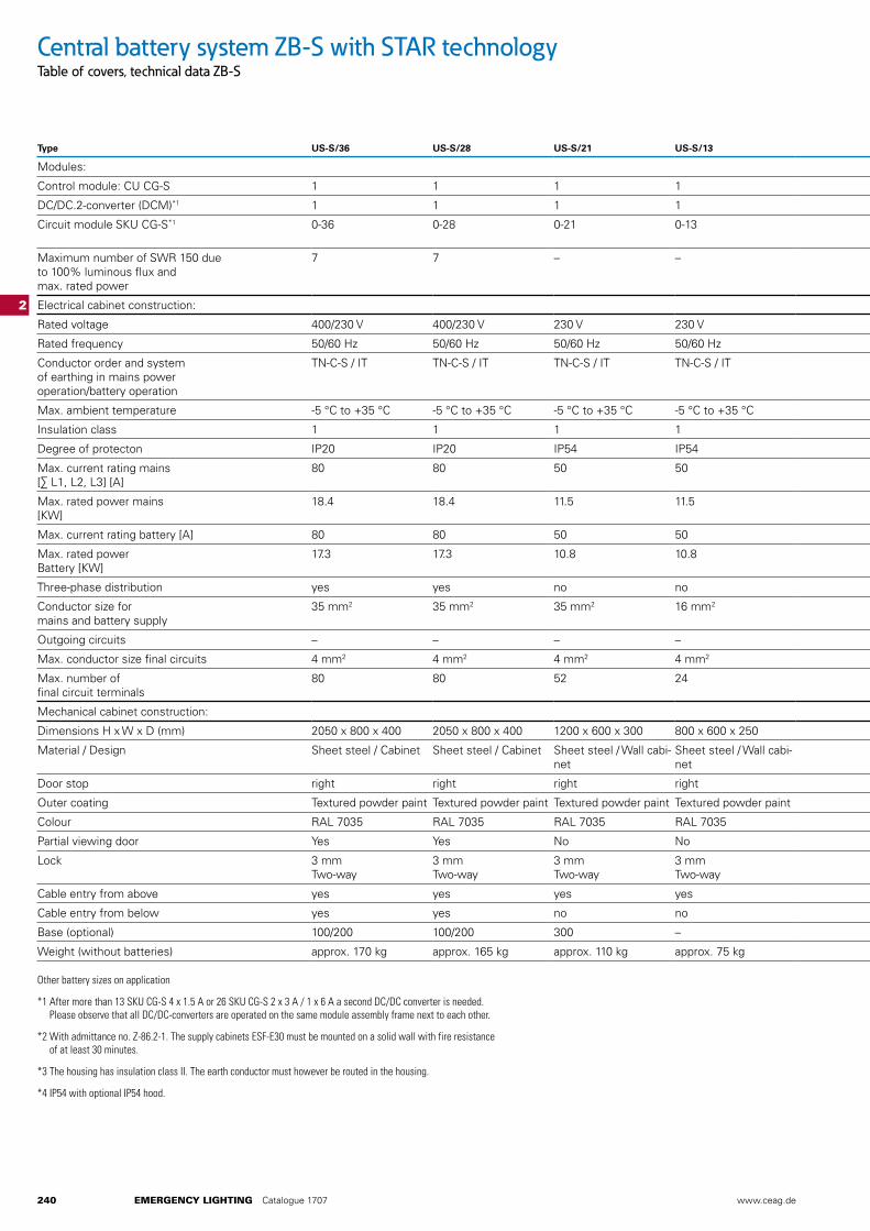
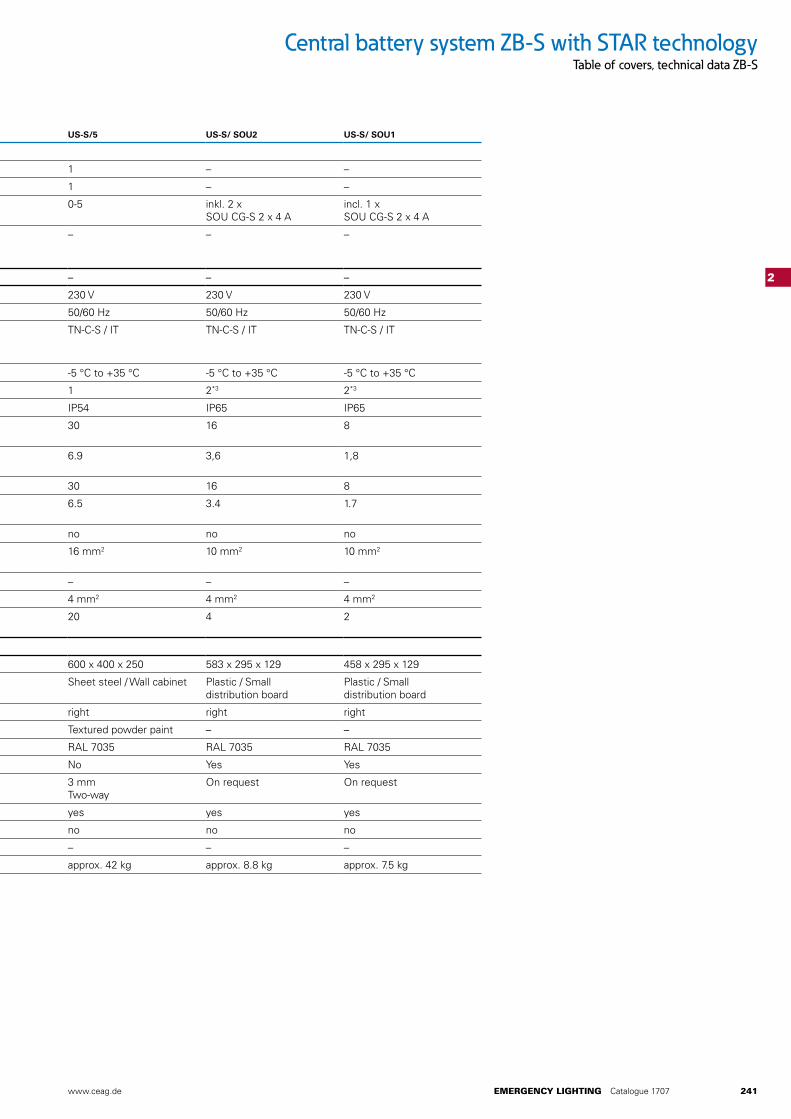
Central battery system ZB-S with STAR technologyTable of covers, technical data ZB-S
Type US-S/36 US-S/28 US-S/21 US-S/13 US-S/5 US-S/ SOU2 US-S/ SOU1
Modules:
Control module: CU CG-S 1 1 1 1 1 – –
DC/DC.2-converter (DCM)*1 1 1 1 1 1 – –
Circuit module SKU CG-S*1 0-36 0-28 0-21 0-13 0-5 inkl. 2 xSOU CG-S 2 x 4 A
incl. 1 xSOU CG-S 2 x 4 A
Maximum number of SWR 150 due to 100% luminous flux and max. rated power
7 7 – – – – –
Electrical cabinet construction: – – –
Rated voltage 400/230 V 400/230 V 230 V 230 V 230 V 230 V 230 V
Rated frequency 50/60 Hz 50/60 Hz 50/60 Hz 50/60 Hz 50/60 Hz 50/60 Hz 50/60 Hz
Conductor order and system of earthing in mains power operation/battery operation
TN-C-S / IT TN-C-S / IT TN-C-S / IT TN-C-S / IT TN-C-S / IT TN-C-S / IT TN-C-S / IT
Max. ambient temperature -5 °C to +35 °C -5 °C to +35 °C -5 °C to +35 °C -5 °C to +35 °C -5 °C to +35 °C -5 °C to +35 °C -5 °C to +35 °C
Insulation class 1 1 1 1 1 2*3 2*3
Degree of protecton IP20 IP20 IP54 IP54 IP20 IP65 IP65
Max. current rating mains [∑ L1, L2, L3] [A]
80 80 50 50 30 16 8
Max. rated power mains [KW]
18.4 18.4 11.5 11.5 6.9 3,6 1,8
Max. current rating battery [A] 80 80 50 50 30 16 8
Max. rated power Battery [KW]
17.3 17.3 10.8 10.8 6.5 3.4 1.7
Three-phase distribution yes yes no no no no no
Conductor size for mains and battery supply
35 mm2 35 mm2 35 mm2 16 mm2 16 mm2 10 mm2 10 mm2
Outgoing circuits – – – – – – –
Max. conductor size final circuits 4 mm2 4 mm2 4 mm2 4 mm2 4 mm2 4 mm2 4 mm2
Max. number of final circuit terminals
80 80 52 24 20 4 2
Mechanical cabinet construction:
Dimensions H x W x D (mm) 2050 x 800 x 400 2050 x 800 x 400 1200 x 600 x 300 800 x 600 x 250 600 x 400 x 250 583 x 295 x 129 458 x 295 x 129
Material / Design Sheet steel / Cabinet Sheet steel / Cabinet Sheet steel / Wall cabi-net
Sheet steel / Wall cabi-net
Sheet steel / Wall cabinet Plastic / Small distribution board
Plastic / Small distribution board
Door stop right right right right right right right
Outer coating Textured powder paint Textured powder paint Textured powder paint Textured powder paint Textured powder paint – –
Colour RAL 7035 RAL 7035 RAL 7035 RAL 7035 RAL 7035 RAL 7035 RAL 7035
Partial viewing door Yes Yes No No No Yes Yes
Lock 3 mm Two-way
3 mm Two-way
3 mm Two-way
3 mm Two-way
3 mmTwo-way
On request On request
Cable entry from above yes yes yes yes yes yes yes
Cable entry from below yes yes no no no no no
Base (optional) 100/200 100/200 300 – – – –
Weight (without batteries) approx. 170 kg approx. 165 kg approx. 110 kg approx. 75 kg approx. 42 kg approx. 8.8 kg approx. 7.5 kg
Other battery sizes on application
*1 After more than 13 SKU CG-S 4 x 1.5 A or 26 SKU CG-S 2 x 3 A / 1 x 6 A a second DC/DC converter is needed. Please observe that all DC/DC-converters are operated on the same module assembly frame next to each other.
*2 With admittance no. Z-86.2-1. The supply cabinets ESF-E30 must be mounted on a solid wall with fire resistance of at least 30 minutes.
*3 The housing has insulation class II. The earth conductor must however be routed in the housing.
*4 IP54 with optional IP54 hood.
www.ceag.de EMERGENCY LIGHTING Catalogue 1707 241
2
Central battery system ZB-S with STAR technologyTable of covers, technical data ZB-S
Type US-S/36 US-S/28 US-S/21 US-S/13 US-S/5 US-S/ SOU2 US-S/ SOU1
Modules:
Control module: CU CG-S 1 1 1 1 1 – –
DC/DC.2-converter (DCM)*1 1 1 1 1 1 – –
Circuit module SKU CG-S*1 0-36 0-28 0-21 0-13 0-5 inkl. 2 x SOU CG-S 2 x 4 A
incl. 1 x SOU CG-S 2 x 4 A
Maximum number of SWR 150 due to 100% luminous flux and max. rated power
7 7 – – – – –
Electrical cabinet construction: – – –
Rated voltage 400/230 V 400/230 V 230 V 230 V 230 V 230 V 230 V
Rated frequency 50/60 Hz 50/60 Hz 50/60 Hz 50/60 Hz 50/60 Hz 50/60 Hz 50/60 Hz
Conductor order and system of earthing in mains power operation/battery operation
TN-C-S / IT TN-C-S / IT TN-C-S / IT TN-C-S / IT TN-C-S / IT TN-C-S / IT TN-C-S / IT
Max. ambient temperature -5 °C to +35 °C -5 °C to +35 °C -5 °C to +35 °C -5 °C to +35 °C -5 °C to +35 °C -5 °C to +35 °C -5 °C to +35 °C
Insulation class 1 1 1 1 1 2*3 2*3
Degree of protecton IP20 IP20 IP50 IP20 IP54 IP65 IP65
Max. current rating mains [∑ L1, L2, L3] [A]
80 80 50 50 30 16 8
Max. rated power mains [KW]
18.4 18.4 11.5 11.5 6.9 3,6 1,8
Max. current rating battery [A] 80 80 50 50 30 16 8
Max. rated power Battery [KW]
17.3 17.3 10.8 10.8 6.5 3.4 1.7
Three-phase distribution yes yes no no no no no
Conductor size formains and battery supply
35 mm2 35 mm2 35 mm2 16 mm2 16 mm2 10 mm2 10 mm2
Outgoing circuits – – – – – – –
Max. conductor size final circuits 4 mm2 4 mm2 4 mm2 4 mm2 4 mm2 4 mm2 4 mm2
Max. number of final circuit terminals
80 80 52 24 20 4 2
Mechanical cabinet construction:
Dimensions H x W x D (mm) 2050 x 800 x 400 2050 x 800 x 400 1200 x 600 x 300 800 x 600 x 250 600 x 400 x 250 583 x 295 x 129 458 x 295 x 129
Material / Design Sheet steel / Cabinet Sheet steel / Cabinet Sheet steel / Wall cabi-net
Sheet steel / Wall cabi-net
Sheet steel / Wall cabinet Plastic / Small distribution board
Plastic / Small distribution board
Door stop right right right right right right right
Outer coating Textured powder paint Textured powder paint Textured powder paint Textured powder paint Textured powder paint – –
Colour RAL 7035 RAL 7035 RAL 7035 RAL 7035 RAL 7035 RAL 7035 RAL 7035
Partial viewing door Yes Yes No No No Yes Yes
Lock 3 mmTwo-way
3 mmTwo-way
3 mmTwo-way
3 mmTwo-way
3 mm Two-way
On request On request
Cable entry from above yes yes yes yes yes yes yes
Cable entry from below yes yes no no no no no
Base (optional) 100/200 100/200 300 – – – –
Weight (without batteries) approx. 170 kg approx. 165 kg approx. 110 kg approx. 75 kg approx. 42 kg approx. 8.8 kg approx. 7.5 kg
258 EMERGENCY LIGHTING Catalogue 1707 www.ceag.de
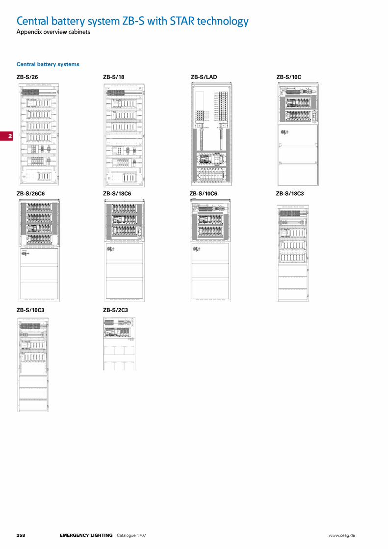
Central battery system ZB-S with STAR technologyAppendix overview cabinets
2
Central battery systems
ZB-S/26 ZB-S/18 ZB-S/LAD ZB-S/10C
ZB-S/10C6ZB-S/18C6 ZB-S/18C3ZB-S/26C6
ZB-S/10C3 ZB-S/2C3
9
E
D
F
C
54321
F
E
D
C
B
A
6 7 8 9
G
H
I
J J
I
H
G
10 11 12
87654321
13 14 15 16 17
K
L
B
K
L
10 11 12 13 14
Norm-geprüft/checked
11DA0ZB-S 10C3 LSCSBG ZB-S LSC 40071361230
1:5
3.3.16 Blüggel
± 0,2
Erstellt mit/generated with
SolidWorks
CEAG-Sachnummer/ CEAG-part number
Maßstab/ scale
Teilecode/part code
Anz.Blatt/sheets
Blatt-Nr./sheet-No.
Sprache/language
Format/size
Separate Stückliste anderer Nummer/separate part list with di�erent number
Separate Stückliste gleicher Nummer/separate part list with same number
Ohne separate Stückliste/without separate part list
Name/name
Datum/date
Änderung/modi�cation
Stand/index
Benennung/ designation
Werksto�/ material
Freim.-Toleranz/ tolerance
Winkel/ angle
Radius/ radius
Längen/ length
Entstanden aus/developed from
Ersatz für/replacement for
Ersetzt durch/replaced by
Freigegeben/approved
Geprüft/checked
Erstellt/issued
± 0,2± 0,2
CTQ
Frei von Verschmutzung und Fremdsto�en, Einfallstellen, Lunker, Fließlinien, Grat und Rissen. Abweichungen müssen über Grenzmuster gesondert vereinbart werden. Free of dirt and unfamiliar materials, sink marks, voids, burrs, �ow marks and cracks. Deviations have to be agreed upon boundary samples.
X
Rechtlich geschützt und vertraulich/Proprietary and Con�dential Schutzvermerk ISO 16016 beachten/Attention to protective note ISO 16016
9
E
D
F
C
54321
F
E
D
C
B
A
6 7 8 9
G
H
I
J J
I
H
G
10 11 12
87654321
13 14 15 16 17
K
L
B
K
L
10 11 12 13 14
Norm-geprüft/checked
11DA0ZB-S 18C3 LSCSBG ZB-S LSC 40071361232
1:5
3.3.16 Blüggel
± 0,5
Erstellt mit/generated with
SolidWorks
CEAG-Sachnummer/ CEAG-part number
Maßstab/ scale
Teilecode/part code
Anz.Blatt/sheets
Blatt-Nr./sheet-No.
Sprache/language
Format/size
Separate Stückliste anderer Nummer/separate part list with di�erent number
Separate Stückliste gleicher Nummer/separate part list with same number
Ohne separate Stückliste/without separate part list
Name/name
Datum/date
Änderung/modi�cation
Stand/index
Benennung/ designation
Werksto�/ material
Freim.-Toleranz/ tolerance
Winkel/ angle
Radius/ radius
Längen/ length
Entstanden aus/developed from
Ersatz für/replacement for
Ersetzt durch/replaced by
Freigegeben/approved
Geprüft/checked
Erstellt/issued
± 0,5± 0,5
CTQ
Frei von Verschmutzung und Fremdsto�en, Einfallstellen, Lunker, Fließlinien, Grat und Rissen. Abweichungen müssen über Grenzmuster gesondert vereinbart werden. Free of dirt and unfamiliar materials, sink marks, voids, burrs, �ow marks and cracks. Deviations have to be agreed upon boundary samples.
X
Rechtlich geschützt und vertraulich/Proprietary and Con�dential Schutzvermerk ISO 16016 beachten/Attention to protective note ISO 16016
9
E
D
F
C
54321
F
E
D
C
B
A
6 7 8 9
G
H
I
J J
I
H
G
10 11 12
87654321
13 14 15 16 17
K
L
B
K
L
10 11 12 13 14
Norm-geprüft/checked
11DA0ZB-S 26 LSCSBG ZB-S LSC 40071361280
1:10
10.3.16 Blüggel
Erstellt mit/generated with
SolidWorks
CEAG-Sachnummer/ CEAG-part number
Maßstab/ scale
Teilecode/part code
Anz.Blatt/sheets
Blatt-Nr./sheet-No.
Sprache/language
Format/size
Separate Stückliste anderer Nummer/separate part list with di�erent number
Separate Stückliste gleicher Nummer/separate part list with same number
Ohne separate Stückliste/without separate part list
Name/name
Datum/date
Änderung/modi�cation
Stand/index
Benennung/ designation
Werksto�/ material
Freim.-Toleranz/ tolerance
Winkel/ angle
Radius/ radius
Längen/ length
Entstanden aus/developed from
Ersatz für/replacement for
Ersetzt durch/replaced by
Freigegeben/approved
Geprüft/checked
Erstellt/issued
CTQ
Frei von Verschmutzung und Fremdsto�en, Einfallstellen, Lunker, Fließlinien, Grat und Rissen. Abweichungen müssen über Grenzmuster gesondert vereinbart werden. Free of dirt and unfamiliar materials, sink marks, voids, burrs, �ow marks and cracks. Deviations have to be agreed upon boundary samples.
X
Rechtlich geschützt und vertraulich/Proprietary and Con�dential Schutzvermerk ISO 16016 beachten/Attention to protective note ISO 16016
9
E
D
F
C
54321
F
E
D
C
B
A
6 7 8 9
G
H
I
J J
I
H
G
10 11 12
87654321
13 14 15 16 17
K
L
B
K
L
10 11 12 13 14
Norm-geprüft/checked
11DA0ZB-S 18 LSCSBG ZB-S LSC 40071361281
1:10
11.3.16 Blüggel
Erstellt mit/generated with
SolidWorks
CEAG-Sachnummer/ CEAG-part number
Maßstab/ scale
Teilecode/part code
Anz.Blatt/sheets
Blatt-Nr./sheet-No.
Sprache/language
Format/size
Separate Stückliste anderer Nummer/separate part list with di�erent number
Separate Stückliste gleicher Nummer/separate part list with same number
Ohne separate Stückliste/without separate part list
Name/name
Datum/date
Änderung/modi�cation
Stand/index
Benennung/ designation
Werksto�/ material
Freim.-Toleranz/ tolerance
Winkel/ angle
Radius/ radius
Längen/ length
Entstanden aus/developed from
Ersatz für/replacement for
Ersetzt durch/replaced by
Freigegeben/approved
Geprüft/checked
Erstellt/issued
CTQ
Frei von Verschmutzung und Fremdsto�en, Einfallstellen, Lunker, Fließlinien, Grat und Rissen. Abweichungen müssen über Grenzmuster gesondert vereinbart werden. Free of dirt and unfamiliar materials, sink marks, voids, burrs, �ow marks and cracks. Deviations have to be agreed upon boundary samples.
X
Rechtlich geschützt und vertraulich/Proprietary and Con�dential Schutzvermerk ISO 16016 beachten/Attention to protective note ISO 16016
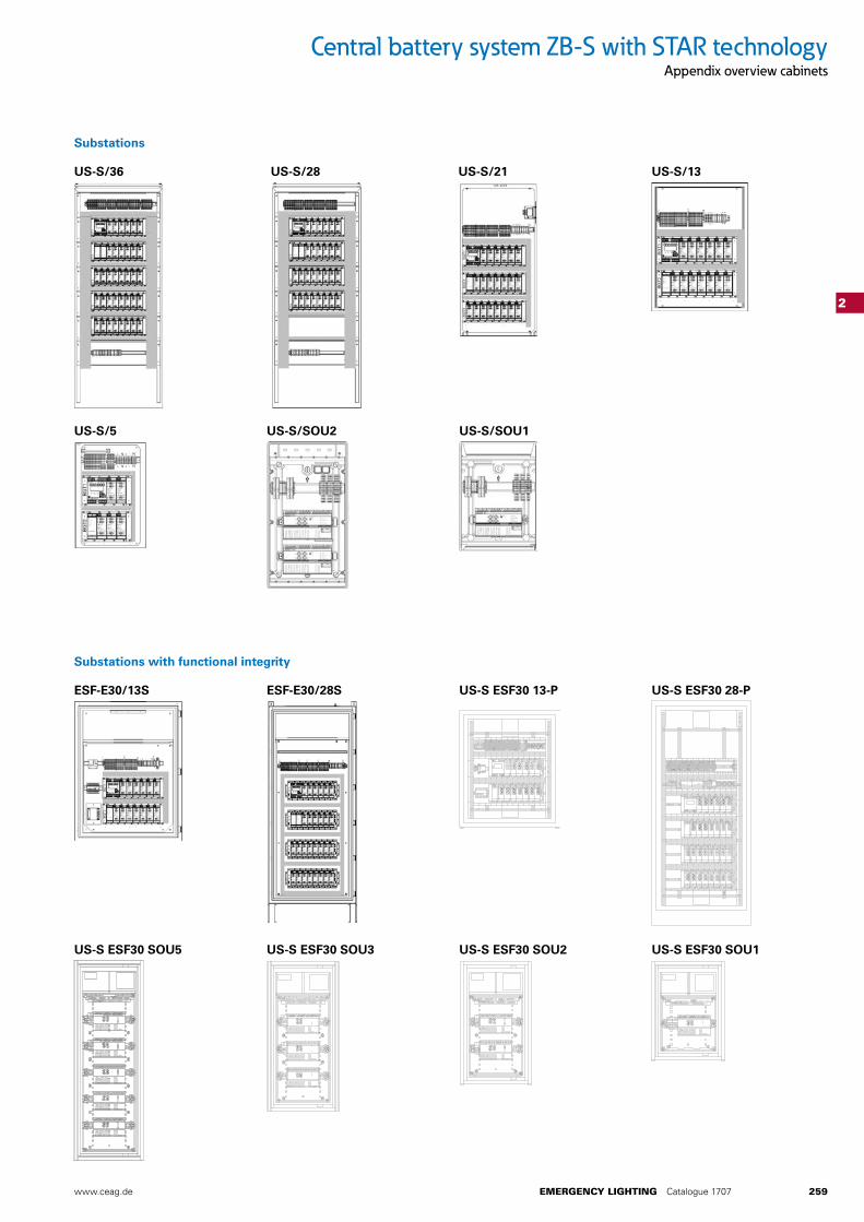
www.ceag.de EMERGENCY LIGHTING Catalogue 1707 259
Central battery system ZB-S with STAR technologyAppendix overview cabinets
2
US-S/36 US-S/28 US-S/21 US-S/13
US-S/SOU2US-S/5 US-S/SOU1
ESF-E30/13S US-S ESF30 13-PESF-E30/28S US-S ESF30 28-P
US-S ESF30 SOU5
230
396
1135
US-S ESF30 SOU3
396
230
835
US-S ESF30 SOU2
396
230
685
US-S ESF30 SOU1
230
535
396
Substations
Substations with functional integrity
918 36,14
1068
42,05
496
19,53
1068
496
918
918 36,14
2068
81,42
596
23,46
2068
918
596