Embed Size (px)
Citation preview

February 2008 www.veritest.com • [email protected]
Features and Functionality Study Comparing File Services Solutions from NetApp and EMC
Test report prepared under contract from Network Appliance, Inc (NetApp)
Executive summary NetApp commissioned VeriTest, the testing service of Lionbridge Technologies, Inc., to conduct a study comparing the features and functionality of the NetApp® FAS3040 running Data ONTAP® v7.2.3 and the EMC Corporation (EMC) Celerra NS40g running DART v5.5.30-5 when used as network-attached storage (NAS) solutions in a File Services environment utilizing the Common Internet File System (CIFS) and Network File System (NFS) protocols. Please refer to the following URL to review the VeriTest Fair Testing Practices Statement: http://www.lionbridge.com/lionbridge/en-US/services/outsourced-testing/veritest-fair-testing-practices-statement.htm Both the NetApp solution and the EMC solution provide file services for Windows® and UNIX® environments. In addition, these NAS-based solutions provide on-disk data retention capabilities or back-up that increase customer efficiency. The purpose of this study is to explore the relative capabilities provided by the NetApp and EMC NAS storage solutions under test. To accomplish this we created a fictitious, midsize enterprise company called ACME Corp. ACME is considering the deployment of a unified NAS solution to meet the growing file serving needs of their user directories, test/development and web workloads. ACME would like to compare the features and functionality of both the NetApp and EMC NAS solutions while focusing on common tasks the ACME storage administrators face when managing a network-attached storage solution on a daily basis. For this NAS solution comparison study, ACME Corp. had the following requirements:
• The data to be stored represents important, but not mission-critical data. • A minimum of 500 GB of usable storage is required to meet the storage space requirements.
Key findings
� The EMC solution takes 4 times longer to complete initial setup and configuration than the NetApp solution.
� The NetApp solution uses as much as 80% less provisioned storage compared to the EMC solution when storing the same files and their corresponding point-in-time backup copies.
� The NetApp solution can dynamically reduce the size of provisioned storage without impacting availability of the file system. The EMC solution does not have this capability.
� Data retention schedules with the NetApp solution can be modified 9 times faster than with the EMC solution.
� The NetApp solution using RAID-DP® continued to serve data in the event of double-disk failure in the same RAID group where as the EMC recommended RAID 5 setup failed when subjected to a double disk failure in the same RAID group.
� The EMC solution required twice the amount of provisioned storage than the NetApp solution in order to provide multi protocol file systems with Operating System integrated security permissions in place.

NAS Comparison Using NetApp Data ONTAP and EMC Celerra DART 2
• The storage solution must provide full support for file storage and serving using the Common Internet File System (CIFS) and Network File System (NFS) v3 protocols.
• The storage solution must integrate within a multi-protocol, multi-OS environment including Windows® Server 2003 Active Directory, and Red Hat Enterprise Linux AS 4 NFS services.
• The storage solution must provide a mechanism to preserve “point-in-time” on-disk copies of data throughout the day-to-day processing that utilizes the storage solution. In addition, because of the dynamic nature of the ACME environment, the storage solution’s mechanism for preserving point-in-time on disk copies must be able to be dynamically modified to meet changing Service Level Agreements (SLAs). The NetApp solution provides this capability, referenced as “Snapshot™ copies”. The EMC solution provides this capability, and is referenced as “checkpoints.”
• The storage solution must be able to provide “online” storage re-provisioning, or in other words, be able to grow and shrink the storage allocation without requiring their production environment to be brought offline for the resize operation to occur.
In addition, the following requirements were determined by ACME Corp. to be highly desired, but not mandatory requirements, for the solution as they would potentially increase storage efficiency and return on investment:
• The ability of the storage solution to provide continued resiliency beyond a single disk failure. • The ability of the storage solution to provide thin provisioning of storage. Thin provisioning provides
storage on demand while traditional provisioning pre-allocates storage. With thin provisioning, storage is treated as a shared resource pool and is consumed only as each individual volume requires it.
• The ability of the storage solution to provide secure access to storage in a multi-protocol (i.e. both CIFS and NFS) environment with minimal storage administration overhead.
For this study we configured a NetApp FAS3040 with Data ONTAP 7.2.3 to test the NetApp File Services solution and compared that with the EMC File Services solution utilizing an EMC Celerra NS40G with Celerra Software version 5.5.30-5. An EMC CLARiiON CX3-40c storage array using Fibre Channel fabric switch connectivity was used for back-end storage of the Celerra solution. Both storage platforms contained a single disk tray. The NetApp solution provides 14 x 144 GB Fibre Channel disks at 15,000 RPM. The EMC solution provides 15 x 146 GB Fibre Channel disks at 15,000 RPM. In addition we configured a Microsoft Windows Server 2003 Active Directory (AD) domain controller to access the provisioned storage on each storage platform using the CIFS protocol. A Red Hat Enterprise Linux AS 4 server was configured to access each storage platform using the NFS protocol. We connected each device to the network with a 3COM gigabit Ethernet switch. As we constructed the ACME File Services environment, we conducted a series of tests to compare the features and functionality for both the NetApp and EMC NAS solutions. These tests were developed to ensure several key aspects of storage administration were addressed in order to validate that the above requirements were met by each solution. The list below provides a high-level overview of these test cases:
• Compare the process of initial device configuration and deployment within a Windows and UNIX/Linux environment for both solutions
• Compare how well both solutions utilize their storage capacity. • Compare the functionality of both solutions to execute common storage administration tasks,
including, but not limited to, modifying existing data retention schedules as service level agreements change and resizing storage provisioning as storage space needs change.
• Compare resiliency to disk failures resiliency on both solutions, while meeting the capacity requirements identified by ACME Corp.
• Compare features and functionality for both solutions when implementing thin provisioned storage • Compare the ability for both solutions to provide secure access to storage in a multi-protocol
environment. In summary, we found that the NetApp solution meets all the requirements as set forth by ACME Corp., and in many cases exceeds these requirements by offering better provisioning management solutions, more robust and feature rich data retention capabilities, and greater failure resiliency.

NAS Comparison Using NetApp Data ONTAP and EMC Celerra DART 3
Although the EMC solution was able to meet most of the core requirements identified by ACME Corp., in comparison with the NetApp solution, we found the EMC solution was less intuitive and took longer to complete the same set of basic tasks. Additionally, we found the EMC GUI management interface was less stable than the NetApp solution. The EMC solution did not meet the ACME requirement of providing “online” storage re-provisioning with regards to reducing the size of a file system storage allocation. Based upon the results of our findings, the NetApp solution meets the unified, multiprotocol NAS storage needs (and in many cases, exceeds them) of ACME Corp, whereas the EMC solution does not meet all requirements. Additionally, we found that the EMC solution was unable to complete the thin provisioned data staging workload performed in this study, whereas the NetApp solution completed this without issue. The NetApp solution was more easily able to restrict access to provisioned storage based upon the end-user’s platform with the use of the NetApp qtree technology. EMC required three different file systems to achieve the same level of multi-protocol support the NetApp system achieved with a single file system. Finally, we found that the EMC solution did not provide the same level of disk failure resiliency as provided by the NetApp solution. Specifically, the EMC solution did not withstand the near simultaneous removal of two disks from the same RAID group while the NetApp solution using RAID-DP continued to provide access to all file systems under the same scenario. It is possible to configure RAID-6 on the EMC solution to provide protection from a double disk failure. However, this required that we deviate from the EMC Celerra NAS best practices and would have also resulted in the EMC solution not meeting the minimum storage requirements listed for ACME Corp. The remainder of this section summarizes the results of the tests we conducted, covering the initial configuration and deployment, storage re-provisioning, data retention schedule modification, disk failure resiliency and thin provisioning comparisons. Complete details on the test cases including the results and methodology can be found later on in the report.
Completing Initial Configuration and Deployment Both the NetApp and EMC solutions use a web based Graphical User Interface (GUI) to manage the configuration, and daily management of the NAS solution. In addition both GUIs provide initial configuration wizards that are used to complete initial configuration tasks. These tasks include the setting of various network parameters to be used by the NAS solution (e.g., IP address, netmask, gateway, DNS configuration, NIS configuration, NTP, etc), as well as the joining of the NAS device to a Windows Server 2003 Active Directory domain. We found it took 4 times longer to initially configure, provision, and make use of the Windows file system with the EMC solution than the NetApp solution. In addition, the number of steps required to complete the tasks were more than double the number of steps required for the NetApp solution. These results are reported in Table 1 below.
Product Number of Steps Time Required to Complete (seconds)
NetApp FAS3040 w/Data ONTAP 7.2.3 75 444 EMC Celerra NS40G w/DART 5.5.30-5 157 1,879
Table 1: Initial Configuration and Deployment
We also encountered an issue with the EMC solution’s ability to join a Windows Server 2003 AD domain using the management GUI when complex passwords were being utilized on the Windows AD server. A considerable amount of time was spent trouble-shooting an error message received when trying to join the ACME Corp. Windows AD domain via the EMC management GUI. Two commands needed to be executed over the command line interface (CLI) in order to successfully join the Windows AD domain with the EMC solution when using a password with special characters. Further details on this situation are covered in Appendix F.
Storage Utilization Comparison Storage over provisioning is an issue that almost all storage administrators consider when deciding on a storage solution. Over provisioning occurs when more storage is allocated to a file system than is actually required by the file system. Unused ‘provisioned’ storage is essentially wasted storage that results in lower

NAS Comparison Using NetApp Data ONTAP and EMC Celerra DART 4
storage efficiency. To measure storage utilization, we utilized a set of scripts developed to simulate the staging of data to the provisioned file system shared out to the Windows® Server 2003 server. In addition, these scripts simulated a common workload in which data is created and deleted over the course of approximately 48-60 hours. During the data staging process, we configured both the NetApp and EMC solutions to create and preserve a number of point-in-time copies of the data at periodic intervals. At the conclusion of this data staging process, we compared the amount of provisioned storage required to store the staged data and related copies for both the NetApp and EMC solutions. We found the NetApp solution achieved a higher level of storage provisioning utilization than the EMC solution. At the conclusion of this data staging and usage simulation test, we compared the amount of storage that had been provisioned by both the NetApp and EMC solutions. Since the NetApp solution stores the on-disk data retention Snapshot copies in the unused space within the provisioned file system, that solution used 200 GB of provisioned storage at the end of the test. By contrast, the EMC solution requires that on-disk data retention copies be contained within separately allocated provisioned storage. As a result, at the end of our data staging simulation, the EMC solution provisioned a total of 364.8 GB of storage space, of which 214.8 GB of space was allocated to checkpoint storage. This is an 82.4% greater storage allocation by the EMC solution over the NetApp solution. This is also shown in Table 2.
Product Space Allocated to the Production File System
(GB)
Additional Space Allocated to On-Disk Data Retention (GB)
NetApp FAS3040 w/Data ONTAP 7.2.3 200 N/A EMC Celerra NS40G w/DART 5.5.30-5 150 214.8
Table 2: Storage Provisioned at Conclusion of Data Staging
Performing Common Management Tasks Test cases 3, 4, and 5 were developed to simulate common management tasks performed by storage administrators. These test cases compared how well both the NetApp and EMC solutions addressed the need to modify an existing data retention schedule as well as available options to reclaim storage that was over provisioned as a result of the data staging simulation conducted in test case 2. It was found that the NetApp solution provided a more intuitive, easier, and more responsive interface compared to the EMC solution with regard to modification of on-disk data retention policies. The EMC solution required considerably more effort to address a required change to the on-disk data retention schedule initially configured as part of the first test case. It is not uncommon for SLAs to change over time. This creates the need to modify previously configured data backup schedules. Test case 3 was designed to simulate this management task. Other common management tasks storage administrators perform are ongoing assessments of and making modifications to provisioned storage. In environments in which file storage space requirements change frequently, the ability of the storage solution to help facilitate the modification of previously provisioned storage is key. In the NetApp solution, we were able to reduce the file system space allocation while the file system was “online.” End-users could fully access files while the storage administrator reduced the size of the provisioned file system storage. The ability to reduce the provisioned storage allocated to over provisioned file systems and subsequently make that reclaimed storage available to a different file system leads to an increased level of storage efficiency. Unlike the NetApp solution, we found that the EMC solution did not allow the provisioned file system storage to be reduced in size. Two stages of storage reclamation were performed. First, as the direct result of a modified SLA, we removed a group of 24 retained copies of the data generated during the first 24 hours of the staging process on both the NetApp and EMC solutions. Removing these Snapshot copies on the NetApp solution allowed us to reduce the size of the file system on the NetApp solution from 200GB to its original size of 150 GB. Additionally, we found that the NetApp solution allowed us to reclaim the space initially associated with the snapshots and use it for other purposes. Finally, we found that, even after the checkpoints were deleted, the EMC system still continued to hold the space associated with the deleted checkpoints. Because the EMC system did not allow the re-use of the space initially associated with the checkpoints, we found the EMC

NAS Comparison Using NetApp Data ONTAP and EMC Celerra DART 5
solution was now allocating 143% more space than the NetApp solution to store the same set of data. These results are detailed in the Test Results section for Test Case 3. Next, we wanted to determine how much total space could be reclaimed if all but the most recently created point-in-time retention copies were deleted on both the NetApp and EMC NAS solution. It is common for storage administrators to delete older copies that are no longer required. After removing these retention copies, we again were able to reduce the size of the file system on the NetApp solution so that it contained space for the existing data set as well as 20% free space and a 10% Snapshot reservation. At these settings the NetApp provisioned file system was reduced to 63 GB. By contrast, deleting these additional point-in-time copies on the EMC solution did not result in the reduction of the size of its file system, or its provisioned data retention storage. At the end of the day, the EMC solution still consumed 364.8 GB of storage compared to only 63 GB for the NetApp solution. Hence the EMC solution provisioned 479% more disk storage than the NetApp solution. Further details of the results of this exercise are shown in the Test Results section for test case 5. The results of these space reclamation exercises are presented in Table 3 below.
Product Total Allocated Space (pre
reclamation)
Space Allocated (after first
reclamation)
Space Allocated (after extended
reclamation)
NetApp FAS3040 w/Data ONTAP 7.2.3 200 GB 150 GB 63 GB EMC Celerra NS40G w/DART 5.5.30-5 364.8 GB 364.8 GB 364.8 GB
Table 3: Space Reclamation Results
Double-disk Failure Resiliency In addition to meeting all the features and capabilities required to satisfy the needs of ACME Corp., the NetApp solution provides the ability to withstand double-disk failures with the use of RAID-6 equivalent technology called RAID-DP. The EMC solution was not able to meet the storage capacity requirements defined by ACME Corp., while also providing double-disk failure resilience. In order to meet the storage space requirements, the recommended RAID 5 configuration was utilized on the EMC solution. Using RAID-5, the EMC solution is unable to remain online when two disks fail simultaneously within the same RAID group.
Thin Provisioning Comparison Thin provisioning is the concept of flexibly allocating storage on demand. Thin provisioned storage allows for greater flexibility as it allows storage to be more effectively provisioned as demand arises. ACME Corp. is interested in deploying a thin provisioned file system for use in its development and test environment. This test case is designed to compare the features and functionality of the NetApp and EMC solution with regard to a thin provisioned file system. For this test case we created thin provisioned file systems on both the NetApp and EMC solutions, which were initially set at 10 GB in size, and allowed to auto-extend in 10 GB increments up to a maximum size of 100 GB. We then ran a data staging operation, similar to that executed for test case 2, which populated the newly provisioned file system with a set of data files. The exercise simulated a high-volume, small file I/O workload commonly found in home directories, project shares, test and development, web workloads, and workloads generating log files or requiring temporary storage. We were able to successfully complete the data staging process with the NetApp solution. The entire process required 7,512 seconds to complete, and the file system automatically extended from 10 GB to 20 GB as configured to do so. We did not experience any disruption in service due to the auto-expansion occurring. Only a single Snapshot copy was taken during this data staging operation, resulting in 320 KB of Snapshot storage being utilized. By contrast, we were not successful in completing the data staging operation with the EMC solution. Approximately 35 minutes into the staging operation, we noticed the file system had exhausted all of its allocated file pointer references (referred to as inodes) and had begun to use inodes reserved for the root file

NAS Comparison Using NetApp Data ONTAP and EMC Celerra DART 6
system of the Linux machine executing the data generation scripts. What this showed was that with similarly configured thin provisioned file systems the NetApp solution was able to process a workload consisting of a high volume of small files, whereas the EMC solution was not able to process the same workload properly.
NAS Multiprotocol Comparison To compare the multiprotocol capabilities of both the NetApp and EMC solutions, we setup three distinct file system repositories – each with their unique permissions. These included a shared repository for both UNIX/Linux (over NFS) and Windows (over CIFS) users, another restricted only to the UNIX/Linux users (accessible by NFS mounts only) and the last being restricted only to Windows users (accessible only as CIFS shares). Using the NetApp solution, we were able to setup a multi-protocol deployment that included greater storage efficiency, more easily managed on-disk data retention schedules and easily definable security permissions. We found that the EMC solution was not able to achieve the same level of security while maintaining the same level of storage efficiency and manageability. Specifically, using the NetApp solution, we were able to create all three repositories within the same file system using their Qtree functionality and verify that each group of users had the proper access only to their respective areas. The EMC solution required that we create three separate file systems each with the correct set of security access to provide the same level of access. As evidenced by the results we report for test cases 2, 3, 4 and 6, these additional file systems lead to additional storage administration complexity, as well as reduced storage efficiency. NetApp’s capabilities to provide storage efficient point-in-time copies of data as well as reducing the amount of storage provisioned to a file system while reclaiming that space for other usage are clear advantages compared to the EMC solution. Complete details on the test results for each test case can be found within the Test Results section of this study. Details of the test methodology used for each test case can be found within the Test Methodology section of this study.
Test Results This section provides the detailed results of the tests we conducted to compare the features and functionality of the file services solution from NetApp (FAS3040/Data ONTAP 7.2.3) and EMC Celerra (NS40g/DART 5.5.30-5). Please refer to the Test Methodology section of this study for complete details on how we conducted each of the tests.
Results for Test Case #1: Initial Setup and Configuration
The following items needed to be accomplished to complete the requirements of this test case: • Configure the storage platform on the production network. • Join the storage platform to the Windows AD Domain. • Create a 150 GB production file system to be shared out to the Windows AD Domain via the CIFS
protocol. • Create a 20 GB production file system to be shared out to the Red Hat Enterprise Linux server via the
NFS (v3) protocol. • Create an initial data retention policy that took hourly snapshots/checkpoints of the 150 GB file
system, and maintained 72 iterations of them. The starting point for this test case occurs when the storage platform is released to the storage administrator to begin the initial configuration/setup wizard available with each storage solution. After the initial configuration wizard is completed, the steps necessary to create the data retention schedule is compared, and finally the steps required to share the newly provisioned file system to the Windows Server 2003 server via CIFS. The items specifically reported on include the length of time required to complete the steps listed above, as well as the total number of steps involved. An overall rating is applied to the process, and explanation associated with the rating. Also discussed are any unexpected issues encountered during this initial configuration process. Both the NetApp and EMC platforms offer a setup configuration wizard that assists the storage administrator in completing the minimum steps necessary to initially configure the NAS platform for use. Both NAS devices

NAS Comparison Using NetApp Data ONTAP and EMC Celerra DART 7
offer configuration through a web based Graphical User Interface (GUI). However, the EMC solution requires a java runtime environment be initiated beginning with the initial login screen. This leads to a slower process of login and initial startup of the GUI. We found the NetApp solutions Filer View GUI to be more responsive as we worked through the various steps required to complete the initial configuration. There were many instances in which the EMC solution’s GUI would appear to stall as it executed the command initiated from within the GUI. Also, on several occasions we encountered situations in which the EMC solution would lock-up requiring the web browser to be forcefully stopped from within the Windows Task Manager, along with the associated java session. We did not experience any stability issues with the NetApp solution. We found the NetApp FilerView GUI to be very responsive, with virtually no hesitation when interacting with the interface as we completed tasks. The only time we experienced a slight hesitation with the FilerView GUI occurred when we used the embedded CLI. At times we experienced a slight hesitation as text was written out to the embedded terminal window. However, the embedded CLI is only one option for accessing the NetApp storage device. Other options, such as Operating System provided tools (telnet, ssh, rsh), and/or third party applications, such as PuTTY, are fully supported. It is interesting to note that the EMC solution does not offer an embedded CLI option; therefore, any usage of the CLI must be accessed from applications outside the Celerra Manager GUI. At times the Celerra Manager GUI would appear to “stall” and take several seconds to load a page it had just previously loaded more quickly. When using the NetApp GUI, we found we were able to complete the initial configuration of the NetApp platform, the initial setup of the data retention (snapshot) schedule, and the sharing of the 150 GB file system via the CIFS protocol, as well as the 20 GB file system via the NFS protocol, in 444 seconds. By comparison, it took 1,879 seconds to complete these same tasks with the EMC solution. Figure 1 below shows the difference in time taken to complete the initial configuration steps identified above. However, these results do not include the amount of time required to trouble-shoot an issue we encountered when trying to join the EMC Celerra to the Windows Server 2003 AD domain. This issue involved the inability of the EMC GUI to handle complex Windows passwords. Appendix F provides greater detail on this issue. Although this trouble-shooting time is not included in the completion time reported in Figure 1 below, it is worth noting that it required the overall first time configuration to take well over 2 hours to complete. We did not include it in the completion time reported as we decided that once the storage administrator understood this issue, future deployments with the EMC solution would occur in the time reported in Figure 1.
Figure 1: Initial Configuration Completion Time
In addition, it requires nearly three times as many steps to complete the same configuration on the EMC solution as it does with the NetApp solution. This result is reflected in Figure 2 below.

NAS Comparison Using NetApp Data ONTAP and EMC Celerra DART 8
Figure 2: Number of Steps required to Complete Initial Configuration
With regard to usability, we found the NetApp solution to be very easy to navigate with options clearly presented, along with links to online help for each item presented in the GUI. We also found the NetApp GUI to be more responsive than the EMC GUI. We did not experience stability issues with the NetApp solution, whereas we encountered half-dozen instances in which the EMC solution’s GUI needed to be restarted as it would hang at times. We were required to manually end the browser and java processes running associated with the EMC GUI. . Finally, the need to drop out of the EMC Celerra GUI and launch a CLI session in order to join the EMC Celerra to the Windows AD domain was a major concern for our storage administrator. When considering the above factors, we found the NetApp solution to be more intuitive, faster and more stable to work with than the EMC solution. We also found we were able to complete the same tasks in less time, and in fewer steps with the NetApp solution that with the EMC solution. Complete details for the steps undertaken to complete this test case can be found in Appendices E and F.
Results for Test Case #2: Data Staging and On-disk Data Retention Management
This test case involved the execution of several Linux scripts which were used to stage data to the newly provisioned 150 GB file system created in Test Case 1. The entire process of creating and staging the ACME production data required between 48 – 60 hours. These scripts simulate the type of data staging typically seen in workloads like:
• Automated testing – e.g. “lab data collection” • Web Services and hosting – e.g. “web mail” • Server consolidation and migration • User home directory storage • Storage (file) warehousing
In addition, this test case simulates a situation in which the ACME Corp. storage administrator discovers that the original data retention policy configured in Test Case 1 was too aggressive, and that s/he is consuming space more rapidly than initially estimated. During the first 24 hour period of this data staging process, the initial data retention schedule created in Test Case #1 is used to maintain hourly snapshot/checkpoints on the state of the data. At the 24 hour period of the data staging process, it becomes clear to the storage administrator the data retention schedule in place is too aggressive and that space consumption is occurring more rapidly than anticipated. Therefore, a change is made to the data retention schedule and the staging scripts then complete under the less aggressive retention schedule. The goal of this test case was to show how much storage space is consumed by the data retention snapshot/checkpoint files for each storage

NAS Comparison Using NetApp Data ONTAP and EMC Celerra DART 9
platform after this data staging process has fully completed, as well as a comparison between the two solutions with regard to how on-disk data retention policies are managed. What we found was that even though the same data was generated on each storage platform, and the data retention schedule was modified at the same interval for each storage platform, the EMC solution needed to allocated 68% more space in order to accommodate its data retention philosophy. The NetApp solution consumed 128 GB of snapshot space at the conclusion of the data staging process. By contrast, the EMC solution allocated approximately 215 GB of storage space to its checkpoint storage. Figure 3 below represents this result.
Figure 3: Amount of Storage Consumed by Snapshot/Checkpoint Retention
In addition, since the EMC solution allocates checkpoint data separately from the file system storage allocation, the total amount of storage space consumed at the conclusion of the data staging process was 365 GB. With the NetApp solution, snapshot data is stored within the production file system allocation. In order to accommodate the more rapid storage consumption discovered during the initial 24 hours of the data staging operation, the storage administrator would be faced with two options for handling the unexpected growth. Increase the file system manually, or configure the file system to auto-grow as needed. We chose to manually increase the size of the file system from 150 GB to 200 GB to ensure the data staging process would complete. We chose to do the extension manually at this point as we will focus on thin provisioning along with auto-grow associated with that provisioning concept in a later test case (Test Case #6). Even after factoring in the manual increase of the file system on the NetApp solution, the EMC solution still provisioned 82.5% additional storage at the conclusion of the data staging operation. This leads to a much larger over-provisioning situation with the EMC solution than the NetApp solution. Figure 4 below represents this result.
Figure 4: Total Storage Consumption After Data Staging Completes

NAS Comparison Using NetApp Data ONTAP and EMC Celerra DART 10
In addition, we found it took 49 hours to successfully complete the data staging scripts with the FAS3040, whereas it took 57 hours to complete these scripts with the NS40G. The same server and network conditions were in effect for both runs of these scripts. The only difference was the target NAS platform. Figure 5 below shows this result.
Figure 5: Time to Complete Data Staging Scripts
At 24 hours into the data staging process the ACME storage administrator realized the initial data retention policy was too aggressive, which was resulting in more space being consumed by the on-disk data backups than was initially planned. Therefore, the storage administrator needs to modify the existing data retention policy to be less aggressive. To accomplish this s/he needs to move from an hourly snapshot/checkpoint policy with 72 iterations, to a configuration in which 8 snapshots/checkpoints are taken throughout the day (every 3 hours a snapshot/checkpoint occurs), and then retain 24 of those iterations. Due to the NetApp platform storing snapshots within the production file system, we needed to increase the size of the file system from 150 GB to 200 GB to ensure the data staging process would complete without issue. The alternate option would have been to configure the file system volume to auto grow as needed. We chose to do the extension manually at this point as we will focus on thin provisioning along with auto-grow associated with that provisioning concept in a later test case. We found two key points to mention when executing this test case for each storage platform. First, we found we were able to complete the data retention modification in 60 seconds on the NetApp platform. Conversely, it took 537 seconds to complete this task on the EMC platform. Figure 6 below represents this result.
Figure 6: Time Required to Modify Original Data Retention Schedule

NAS Comparison Using NetApp Data ONTAP and EMC Celerra DART 11
This additional time is in direct relation to the need to actually delete the initial data retention schedule setup in Test Case #1 on the EMC solution. With the NetApp solution we simply needed to open Filer View and navigate to the snapshot management screen. Then we de-selected the hours for which we no longer wanted the snapshot to occur, and change the retention from 72 to 24, then click apply. This was all that was required to modify the original retention schedule to the new SLA schedule. However, with the EMC solution we discovered we were unable to modify the number of iterations retained in the original data retention schedule created in test case #1. Therefore, we were required to create a new standard daily schedule, selecting the hours in which we wanted to have the checkpoints taken, along with a new value for the number of iterations to retain. In addition, when first applying this new schedule, we were faced with a warning message indicating that taking checkpoints within a 15 minute period of another checkpoint schedule would lead to performance issues. This conflict comes about due to the need to create a new schedule rather than modify the existing schedule. Therefore, we had to manually set the minutes on the new schedule to be at the 15 minute mark past the hour, rather than the default of on the hour. We then had to delete the original data retention schedule. Once the original checkpoint schedule was deleted, we then went back to the newly created schedule to change the minutes back from 15 minutes past the hour, to be taken on the hour, which was the desired setting. In total we found it took 8 steps to complete this task with the NetApp solution, where as it took 17 steps to complete this task with the EMC solution. Figure 7 below represents this result.
Number of Steps Required to Change Retention Schedule
17
8
0
5
10
15
20
NetApp EMC
# o
f S
tep
s
Figure 7: Number of Steps Required to Modify the Original Data Retention Schedule
We found the overall process is not as easy or intuitive with the EMC solution as it is with the NetApp solution. It took longer to complete and required more steps to accomplish the same task on the EMC solution as it did with the NetApp solution. In addition to the various usability issues described above, we experienced several performance issues when using the EMC solution GUI. There were two occasions when submitting the new checkpoint schedule in which the GUI simply “froze”, resulting in a need to manually end the web browser task and related java runtime environment processes using the Windows Task Manager. This experience actually caused it to take longer than nine minutes to complete the task, however, when the EMC solution’s GUI worked from start to finish without a failure, the process still took just under nine minutes to complete.
Results for Test Case #3: Volume Contraction and Space Reclamation
As discussed above, this test case involved the removal of the snapshots/checkpoints created during the initial 24 hour data staging load as these snapshots were no longer needed. Two key questions were asked by the ACME Corp. storage administrator after the data staging process completed:
1. Can I reclaim space by reducing the size of my production file system? If so, how much space is reclaimed.

NAS Comparison Using NetApp Data ONTAP and EMC Celerra DART 12
2. Can I reclaim space by removing snapshots/checkpoints that are no longer needed? Each gigabyte of storage that is allocated, but not used (over-provisioned) represents a waste of capacity to the ACME Corp. storage administrator. Therefore, with the NetApp solution, deleting these snapshots which are no longer needed, allows the file system to be resized back to the original allocation to reclaim the additional 50 GB that was added to the original allocation to ensure the data staging would complete successfully. In addition, we would recover 80 GB of storage capacity within the provisioned file system originally held by the initial set of snapshots. On the EMC solution, removing the 24 snapshots created during that initial 24 our period did not result in any overall space being reclaimed on the EMC platform. During the data staging load process, the EMC expanded its checkpoint SAVVOL to 214.8 GB to accommodate the amount of space consumed by the checkpoint data. Of this allocation, only 187.8 GB of space was actually being utilized by checkpoint data required as a result of the new SLA requirements. Additionally, we found that removing the initial 24 checkpoints no longer needed, this did not result in the EMC solution reducing the space allocated to the checkpoint volume. This remained at 214.8 GB. Reducing the size of the file system on the NetApp solution back to the original 150 GB allocation, results in an even greater disparity between the amounts of space allocated between the NetApp and EMC solutions to hold the final set of ACME production data. This results in a much higher over-provisioning condition on the EMC when compared to the NetApp solution. Table 4 below highlights the amount of storage capacity we were able to reclaim on each storage platform.
Storage Platform Total Amount of Provisioned
Storage (pre-
reclamation)
Storage Consumption
Reclaimed (remove old snapshots)
Storage Provisioning
Reduction (volume resize)
Total Amount of Provisioned
Storage (post
reclamation)
NetApp FAS3040 w/Data ONTAP 7.2.3 200 GB 80 GB 50 GB 150 GB EMC Celerra NS40G w/DART 5.5.30-5 364.8 GB N/A N/A 364.8 GB
Table 4: Storage Capacity Reclaimed After Old Retention Point Deletion Even though the NetApp solution started off with roughly 100 GB less available capacity due to differing RAID implementations, this space (and then some) was recovered after the data staging process completed. This was done by simply adjusting the provisioned storage without inflicting any risk of data loss, or additional provisioning time, as well as reclaiming space by removing snapshots that were no longer needed. The EMC solution does not reduce the size of its provisioned checkpoint storage when removing the initial 24 checkpoints, and also does not provide the ability to dynamically reduce the size of the provisioned file system. This results in less storage efficiency for ACME Corp. when implementing an EMC solution. .
Results for Test Case #4: Volume Contraction and Space Reclamation - Extended
This test case is an extension to Test Case #4. For the purposes of this test case, we now assume the production file system is more of a “read-only” state. There may be periodic additions to the file system, but for most day-to-day processing it is needed for read-only purposes. As a result, ACME administrators would like to remove all but the most recent data retention point and reduce the size of the volume to include the current data and 30 percent overhead to accommodate infrequent future increases in the size of the data set as well as the occasional additional snapshot. The goal of this test case is to highlight the additional amount of storage that can be reclaimed on both the NetApp and EMC storage platforms to accommodate the new usage patterns of the ACME production data. This type of situation is common in cases in which production data is copied to a non-production location so as to allow QA type services to be conducted. By removing all but the most recent snapshot, and then reducing the file system allocation size, we achieve a higher storage efficiency and utilization with the NetApp solution than with the EMC solution. What we found was that even after removing all the other checkpoints, the EMC solution still reported 202.1 GB of allocated, but unused, space in the checkpoint volume. This is space that is not able to be used for other purposes;

NAS Comparison Using NetApp Data ONTAP and EMC Celerra DART 13
effectively making it wasted space with regard to future file system provisioning needs. In addition, since we are unable to resize the EMC solution’s production file system down to the desired size. We found we had 85 GB of additional allocated space that was going unused out of the originally provisioned 150 GB file system. However, after removing the unnecessary snapshots on the NetApp and reducing the file system to a 20% free space and 10% snapshot allocation, only 63 GB of space needed to be provisioned to this file system, This results in 479% more space provisioned on the EMC solution than the NetApp solution, with both storage platforms containing the same usable data. Figure 8 below represents this result.
Figure 8: Amount of Provisioned Space After Extended Reclamation
The inability to reduce the size of the file system with the EMC solution is a major functionality concern for a storage administrator in a dynamic environment in which storage requirements can change quite dramatically. The option of making changes without impeding the availability of the production file system is a key feature available on the NetApp platform. In addition, the process by which resizing of provisioned storage is done is straightforward and intuitive on the NetApp solution. Since the EMC solution does not support this functionality, this is deemed a major deficiency by the ACME Corp. storage administrator.
Results for Test Case #5: Double Disk Failure Capability
Although it is widely understood that a RAID5 implementation is not designed to handle a double-disk failure, the fact the FAS3040 comes standard with the capability to run RAID-DP, and still meet and exceed the other requirements set forth by ACME Corp., we felt it was a worthwhile exercise to demonstrate this added benefit when using the FAS3040 platform. As stated previously, the storage space requirements listed by ACME Corp. require that the hard disks be acquired to meet their current capacity needs, fit within the allocated budget set forth for a NAS solution, and still provide the necessary features and functionality to administer the storage solution requiring the least amount of time and effort. The NetApp solution provides RAID-DP to provide double-disk failure resiliency. RAID-DP is a high performance implementation of RAID 6 that provides double parity across the disk subsystem. Like RAID-6 it is intended to protect against the simultaneous failure of up to two disks per RAID group. Although the EMC solution does provide the potential for a RAID-10 or RAID-6 implementation, this would not be possible with the planned configuration. There simply would not have been enough available storage to meet the minimum space requirements identified to meet the various ACME Corp. file systems to be configured. In addition, using RAID-6 was not an option as to implement this RAID type on the backend CLARiiON device would have led to a need to break from EMC recommendations for the Celerra allocation template. Once the 150 GB file system was online, we started a series of scripts that put a light load on the systems and monitored the activity occurring on the file system. We then conducted a test to evaluate the resiliency of

NAS Comparison Using NetApp Data ONTAP and EMC Celerra DART 14
the NetApp and EMC platforms by manually pulling a single disk from each system. Both RAID types utilized on each platform withstood a single-disk failure without any disruption in service experienced by the end user. After pulling the initial disk from each system, we waited a total of 5 minutes and then manually pulled a second disk from the production RAID group. While monitoring the production file system, we found there was no disruption of service experienced by the end user when using the NetApp Solution. However, the EMC solution was not able to continue serving the production file system when a double-disk failure occurred. When the first disk failure occurred there was a slight pause in the processing of the two commands, but the pause was essentially momentary. However, when the second disk failed, the file system was no longer available to the end user indicated by the failure of the monitoring scripts running against the production file system. This test highlights the greater availability with the NetApp solution. In addition to the numerous other advantages highlighted in the study, the NetApp solution also affords greater resiliency to double-disk failure situations, while still providing as much (and under many situations as described in other test cases) more available storage to the ACME Corp. storage administrator.
Results for Test Case #6: Thin Provisioning
Thin Provisioning is the concept of flexibly allocating storage on demand. Thin provisioned storage often leads to a greater flexibility as it allows storage to be more effectively provisioned as demand requires. ACME Corp. is interested in deploying a thin provisioned file system for use in their development environment. This test case is designed to compare the features and functionality of the NetApp and EMC solution with regard to a Thin Provisioned file system. This test case compares the process involved in creating a thin provisioned file system on the NetApp and EMC solutions. In addition, we performed a data staging operation similar to what was done in Test Case 2 to compare how well the FAS3040 and NS40G handles auto-extension of the file system. We also recorded if any issues encountered when staging data to a thin provisioned file system on each platform. Creating a thin provisioned file system on the FAS3040 and NS40G is similar in terms of time to complete and the number of steps involved. Appendices I and J provide details regarding the process involved in setting up a Thin Provisioned file system for each storage platform. After creating the file system, enabling a CIFS share, and setting up the initial data retention policy, we also setup the file system to be shared via NFS. We then used our Linux system to NFS mount the file system and launched the data staging scripts from that Linux system. The thin-provisioned file system was configured to be 10 GB in size at the outset. The scripts were designed to generate approximately 20 GB of data that required the file system to grow automatically as the amount of data written to the file system exceeded the initial size. At the end of the scripts a total of 20 GB of data had been written to the file system. These scripts functioned very similarly to the scripts run for Test Case 1. A directory structure was created in which thousands of files were created using the Linux ‘dd’ command. Some common file systems in which a thin provisioned approach would be ideal are listed below:
• Server log files • Temp storage • Document repositories • File server consolidation • User directory consolidation
We found that we were able to successfully complete the data staging process with the NetApp solution. The entire process required 7512 seconds to complete, and the file system automatically extended from 10 GB to 20 GB as configured to do so. We did not experience any disruption in service due to the auto-expansion occurring. A single point-in-time snapshot of the file system was taken during this data staging operation, resulting in 320 KB of snapshot storage being utilized. By contrast, the EMC solution failed during the data staging process. Approximately 35 minutes into the staging operation, we found all available inodes had been exhausted in the thin provisioned file system with

NAS Comparison Using NetApp Data ONTAP and EMC Celerra DART 15
the EMC solution, and therefore we had to manually stop the scripts. Although we did not experience any disruption in the staging of the data, we noticed the root file system of the Linux server was losing inodes due to the exhaustion of inodes on the thin provisioned file system. Upon further examination we discovered the thin provisioned file system had exhausted all inodes automatically allocated by the EMC solution. The available inodes are determined at the block level of the EMC solution, and is not modifiable by the storage administrator. This situation could lead to the system NFS mounting the share to eventually crash if all the root level inodes were to be exhausted. The ability to modify allocated inodes with the NetApp solution provides additional flexibility to the storage administrator to customize the storage solution to meet their particular storage needs, and is a feature lacking on the EMC solution. In addition, we found that the NetApp solution reported the correct size of the thin provisioned file system to the Linux server before and after the data generation at 10GB and 20GB respectively. However, with the EMC solution, the Linux server was presented with a file system size of 100 GB, which was the maximum to which the file system was allowed to grow. Setting a maximum size was a requirement by the EMC solution; however, no maximum size limitation was imposed by the NetApp solution. We also looked at the possibility of space reclamation on the thin provisioned file system with regard to both NAS solutions. However, the data staging process failed on the EMC solution before the file system could be extended so we weren’t able to record how this process compared to the NetApp solution. The file system reached 87% capacity on the EMC solution at the time we had to stop the data staging process as a result of the inode exhaustion issue discussed above. As with a traditionally pre-allocated file system, the EMC solution was unable to resize its file system downward. The NetApp solution was able to resize its file system’s current allocation dynamically. We were able to accomplish this by reducing the size of the thin provisioned file system to a 10% free-space allocation of the development file system, as well as reducing our snapshot reserve setting to 5%, after the data population scripts completed successfully. Again, this shows how the ability of the NetApp solution to dynamically re-allocate storage, even from an already thin provisioned file system, to other storage needs can lead to better storage efficiency. With this ability of the NetApp solution, the ACME Corp. storage admin can quickly and painlessly re-provision storage as the ACME Corp. storage environment needs change. The final test we performed with the thin provisioned file system was with regard to a double-disk failure. As with the traditional pre-allocated file system, the EMC solution was unable to continue serving data when a double-disk failure occurred. With the NetApp solution, not only did it continue to serve data as observed via the same ‘ls –alR’ and ‘dd’ commands executed for Test Case 6 above, but we also observed the NetApp solution auto-extend its file system without disruption while the double-disk failure scenario was occurring. This highlights the added storage efficiency ACME Corp. can experience with the NetApp platform due to the added resiliency the platform provides with RAID-DP implementation.
Results for Test Case #7: Multi-Protocol Environment Security Comparison
ACME Corp requires the unified NAS storage solution satisfy the needs of both their Windows and Unix IT support divisions. They need to have a storage location in which both their Windows and UNIX support staff can fully access a shared documentation repository. However, they also need separate storage locations that only Windows support staff and only Unix support staff can access (i.e., Windows staff can’t modify contents of the Unix storage location, and vice-versa). Tied to this is the need to efficiently utilize the available storage. Therefore, ACME needs three (3) file system created, and shared out appropriately with the proper security permissions:
• “Shared” resource: Accessible/Modifiable by both Windows and UNIX IT staff. • “Windows” resource: Modifiable only by Windows IT staff. • “Unix” resource: Modifiable only by UNIX IT staff.
We compared the amount of time and number of steps it took to accomplish the tasks necessary to implement the above requirements, the amount of storage allocated after the completion of the setup and data staging and an initial data retention point was taken.

NAS Comparison Using NetApp Data ONTAP and EMC Celerra DART 16
To address the above requirement with the NetApp solution, we created a single 20 GB Flexible Volume. We then created a CIFS export of this volume and presented it to the Windows AD server. We also created an NFS export of this same FlexVol and presented it to the Linux server. The permission settings for this FlexVol used the default security style unix. Next we utilized the Data ONTAP qtree functionality to create two separate qtrees within this 20 GB FlexVol. The first qtree was setup with the NTFS security style which ensure only proper Windows AD users will have appropriate access to modify data in this qtree, and shared out to the Windows server via a CIFS export. The second qtree created was setup with the Unix security style which ensures only authorized Unix users with the proper User ID (UID) and Group ID (GID) permissions can access and modify the contents of this qtree. Since the security permissions are inherited from the shared top-level file system, and the default setting is defined as the “native” style with the EMC solution, it was not possible to control permissions on any subfolders created within this file system from within the EMC storage management software by using a single file system. In order to meet the above requirements with the EMC solution we had to create three (3) separate file systems. The first file system created was the “Shared” file system that both the Windows and UNIX group had full access to modify. We then created another file system called “Windows” which was shared out using the CIFS protocol to the Windows AD server and assigned the NT security style under the “Custom” option. Finally, we created a third file system called “Unix”. This file system was setup with the custom “Unix” access policy available on the EMC solution. In order to match the total storage allocation between the two NAS solutions, the EMC “shared” file system was given a size of 10 GB, whereas each of the two other OS specific file systems were given a size of 5 GB. Please refer to the Test Methodology section of this study for additional details on how we configured each of the storage solutions to meet the above requirements. Although it took more steps to complete the above requirements with the NetApp solution than it did with the EMC solution, it still required less time to complete the task with the NetApp solution. In addition, the end result was a configuration that resulted in better storage utilization, and an easier to manage configuration. It took 48 steps, and 273 seconds to complete the setup with the NetApp solution, whereas it took 36 steps and 322 seconds with the EMC solution. Table 6 below represents these results.
Storage Device Number of Steps Completion Time Required (sec) NetApp FAS3040 w/Data ONTAP 7.2.3 48 273 EMC Celerra NS40G w/DART 5.5.30-5 36 322
Table 6: Multi-Protocol Environment Security Comparison Setup Results Summary In addition, it required 100% more storage allocation with the EMC solution than with the NetApp solution. This was due to the need to create three separate file systems with the EMC solution in order to setup separate Windows and UNIX storage areas with the required permissions, as well as a shared storage allocation that both platforms can equally access. These results are represented in the Figure 9 below.

NAS Comparison Using NetApp Data ONTAP and EMC Celerra DART 17
Figure 9: Multi-Protocol Shared Storage Allocation
The NetApp solution provides a mechanism referred to as “qtree” which enables the storage administrator to create separate storage partitions. A single storage volume can contain multiple qtrees and individual qtrees within a volume can be assigned different security permissions managed by the NetApp storage solution. This simplifies the administration of these provisioned storage allocations by reducing the number of separate storage pools requiring their own unique data retention policies. The EMC requires the creation of multiple file systems in order to setup permissions necessary to limit NAS protocol based access to the storage allocation. As evidenced by the results presented in test cases 3, 4, 5 and 7, the addition of more file systems with the EMC solution results in an ever more complex and difficult to manage storage solution, when compared to the NetApp solution.
Conclusions
After reviewing the above results, we found the NetApp solution provides a higher return on ACME’s investment under the conditions examined in this study. The NetApp solution provides a more intuitive management GUI, which leads to a shorter initial configuration and deployment time investment. It took the ACME Corp. storage administrator 4 times longer to initially configure the EMC solution compared to the NetApp solution while excluding the time necessary to initially resolve the Windows AD Domain join issue associated with the EMC DART’s inability to handle complex passwords through its GUI management solution. In addition, the added benefits the NetApp solution provides with its ability to dynamically reduce storage allocation without interfering with the production file system’s ability to serve data adds to the overall ease of use associated with the NetApp solution. This ultimately leads to better storage utilization on the NetApp solution, than experienced on the EMC solution. The inclusion of RAID-DP technology with the NetApp solution provides the ability of the production file system to survive a double-disk failure situation without data loss, nor file system downtime, while at the same time meeting the minimum storage space requirements necessary to contain the ACME Corp. data. The EMC solution is not able to meet both these requirements when utilizing the same number of disks. This study also shows that with the same data loaded to each storage platform, the NetApp solution does a better job of avoiding an over-provisioned situation. In addition, any over-provisioning that does occur can be easily addressed on the NetApp solution by either reducing the size of the file system, or by removing snapshots no longer needed.

NAS Comparison Using NetApp Data ONTAP and EMC Celerra DART 18
By contrast, the EMC solution is not able to reduce the size of its file system to reclaim space. Additionally, due to its allocation of checkpoint data to a separate storage volume, the EMC solution ends up provisioning far more storage than might ultimately be required by the file system. This can greatly reduce the storage efficiency ACME Corp. would achieve if the EMC solution were to be implemented. As the test results in this study show, with the same data loaded, the EMC solution can experience an over provisioning situation ranging from 82% to 479% above that required with the NetApp solution. When comparing the data retention capabilities of the NetApp solution to that of the EMC solution, this study has shown it is easier to use the NetApp solution when initially configuring the retention policy. In addition, in the event changes need to be made to the retention policy, the NetApp solution is able to address these changes in a straightforward manner, in which heavy editing of the schedule can be completed within a minute. The EMC solution requires a great deal more time and effort to address any retention policy changes, which also contributes to lower storage efficiency for ACME Corp. when the EMC solution is implemented. When utilized in a multi-protocol environment, the NetApp solution exhibited additional advantages over the EMC solution. These advantages were evidenced by the ability of the NetApp solution to provide the ability to store separate partitionable storage allocation points (qtrees) within the same volume thereby resulting in greater storage efficiency. In addition, the ability to configure qtrees with separate security permissions within the same volume resulted in a more easily managed storage solution for the ACME Corp. storage administrator. In conclusion, the NetApp solution meets all the requirements as set forth by the ACME Corp. storage administrator, and in many cases exceeds these requirements by offering better provisioning management solutions, more robust and feature rich data retention capabilities, and greater failure resiliency. As a result, we believe the NetApp solution would be a better platform to address ACME’s storage requirements compared to the EMC solution.
Test Methodology This section provides the details of the specific test cases we conducted. For the purposes of this study, a fictitious company is referenced, ACME Corp, which has a need to deploy an entry level Enterprise class NAS solution capable of integrating with an existing Windows Server 2003 AD domain, and sharing the provisioned file systems via the CIFS protocol, as well as providing Unix file services using the NFS protocol. We then developed the following test cases to simulate several common scenarios encountered by storage administrators on a daily basis, specifically focusing on provisioning, space reclamation, and retention features and functionality of NetApp and EMC based NAS solutions. Based on the results of these tests, we made a recommendation to ACME regarding which of the storage systems tested better met their needs of their NAS requirements. Before conducting any of the test cases, we configured the basic hardware infrastructure for the Windows Server 2003 domain. This included the installation and configuration of a Windows Server 2003 R2 w/SP2 AD Domain Controller server. This system was used to test the Windows File Services functionality of the storage platforms using the CIFS protocol. This system was configured as a Windows Server 2003 AD server containing DNS, DHCP and Remote Access capabilities. For the purposes of this environment the AD Domain configured was wudss.ppe. Further details on this configuration can be found in Appendix B. A Red Hat Enterprise Linux (RHEL) AS 4 Update 4 system was also installed into the environment. This system was configured to access each storage platform using the NFS protocol. The default package set was installed on this system, and this system was configured with two gigabit Ethernet network interfaces. The first interface was setup to use a separate network dedicated for remote access to the server. The second interface was configured as a dedicated connection to the ACME Corp. NAS environment. Complete details on the configuration of this system can be found in Appendix C. The storage platforms used as the basis for this study included the NetApp FAS3040 running Data ONTAP v7.2.3, and the EMC Celerra NS40G with DART v5.5.30-5 with a CLARiiON CX3-40c storage array. Both the NetApp solution and the EMC solution are configured with a single disk tray configuration as the available

NAS Comparison Using NetApp Data ONTAP and EMC Celerra DART 19
storage to be provisioned. A 3COM Gigabit Ethernet switch was used with a two VLAN configuration to separate NAS and administrative network traffic. VLAN1 controlled the Windows File Services network connectivity in which all CIFS traffic is routed. VLAN2 contained the remote administration links by which RDP, SSH and VNC connectivity to the test systems are established, and separated from the NAS traffic. Please refer to Appendix D for a diagram of the ACME NAS File Services network topology. Both the NetApp and EMC solution provide similar advertised features and functionality that meet the following ACME Corp. requirements:
• The data to be stored represents important, but not mission critical data. • Must provide a minimum of 500GB of usable storage is required to meet the storage requirements. • The NAS solution provides a unified multi-protocol (CIFS and NFS) solution that satisfies the needs of
both their Windows and Unix IT support divisions. • The NAS solution must support multiple OS platforms accessing shared storage simultaneously,
while respecting OS specific security models. • The NAS solution must integrate within a Windows Server 2003 Active Directory Domain. • The NAS solution must provide a mechanism to preserve “point-in-time” on-disk copies of data
throughout the day-to-day processing that utilizes the storage solution. In addition, due to the dynamic nature of the ACME environment, the storage solution’s snapshot technology must be able to be dynamically modified to meet changing Service Level Agreements (SLA). The NetApp solution provides this capability, referenced as “Snapshot copies”. The EMC solution provides this capability, and is referenced as “checkpoints”.
• The NAS solution must support “online” storage re-provisioning. ACME defines this as the ability to grow and shrink storage allocation without requiring their production environment to be brought offline for the resize operation to occur.
The following additional items were determined by ACME Corp. to be desirable but not mandatory requirements for a storage solution and would be considered strong “add-ons” that would greatly increase ACME Corp. storage efficiency:
• The ability of the NAS solution to provide resiliency beyond a single disk failure. • The ability of the NAS solution to provide a Thin Provisioning solution to storage allocation. Thin
provisioning provides storage on demand while traditional provisioning pre-allocates storage. The value of thin provisioned storage is that storage is treated as a shared resource pool and storage is consumed only as each individual volume requires it.
As we constructed the ACME NAS storage solution, we conducted several tests to compare the features and functionality of each storage solution in order to meet the requirements of ACME Corp. listed above. The list below provides a high level overview of these test cases.
• Compare the process of initially configuring the NetApp and EMC storage solutions to provide NAS file services, using the CIFS and NFS protocols, within a data center containing a Windows 2003 AD Domain Controller and a Red Hat Enterprise Linux AS 4 file server. This aspect is covered by the steps conducted in test case 1.
• Compare the ability of the NetApp and EMC storage solution to configure “point-in-time, on-disk” data retention policies. In addition, we also compared the ability of these policies to be modified is also compared. These features are examined during test case 1 and 2 respectively.
• Compare options available, and degree to which space can be reclaimed by the removal of on-disk data retention backups no longer required to be retained. The results for this comparison are reported in test cases 3 and 4.
• Compare the level of data protection afforded by both the NetApp and EMC storage solutions. Discussion on each solution’s capabilities is covered within test case 5.
• Compare flexible (thin) provisioning options afforded by the NetApp and EMC storage solutions. For this test, we utilized a file system that initially consumed a relatively small amount of data but that had the potential to grow considerably and regularly over the life of the storage solution. This capability is examined as part of test case 6.
• Compare multiprotocol NAS security implications between the two solutions. This comparison is conducted as part of test case 7.

NAS Comparison Using NetApp Data ONTAP and EMC Celerra DART 20
For the purposes of this study, a “step” is defined as: • Anytime it was required that a field be completed. • A selection was made within the GUI. • Points in which a click on a step confirmation was needed to proceed to the next step.
The following sections provide the details of the individual test cases.
Test Case #1: Initial Setup and Configuration
The goal of this test case was to compare the amount of effort required to initially provision a 150 GB file system shared out over the CIFS protocol and a 20 GB file system shared out over the NFS protocol, using both the NetApp and EMC solutions. Not included in this comparison were the steps and time required to physically install each storage product. Both NetApp and EMC offer Professional Services Engineers available to be onsite to assist with or completely install the hardware, and prepare the device for surrender to the customer. Once the device is turned over to the customer, the customer is then required to initially configure the device and provision the storage as desired. The starting point for this test case occurs after the point the storage platform is released to the ACME Corp. storage administrator to begin the initial configuration for each storage solution. This includes creating the initial 150GB CIFS file system and another 20GB file system for use by NFS. We then recorded the steps necessary to create the data retention schedule for the 150 GB file system is compared, and finally the steps required in order to share the newly provisioned 150 GB file system to the Windows Server 2003 system using the CIFS protocol, and the 20 GB file system to the RHEL AS 4 server using the NFS protocol. The metrics for this include the length of time required to complete the steps listed above, as well as the total number of steps involved. Both the NetApp and EMC platforms provide Graphical User Interface (GUI) solutions with configuration “wizards” to assist the customer in the process of initially configuring the storage device. The GUI is also used to provision the storage, and make it available for network access. For the remainder of this study, we refer to the 150 GB file system created in this test case as the “Web” file system and the 20 GB file system created in this test case as the “Operations” file system. This test cased focused specifically on the completion of the initial configuration wizard for each storage platform, the provisioning of two file systems, the steps necessary to present one of these file systems to client systems via the CIFS protocol, the steps necessary to present the second file system to another client system via the NFS protocol and finally an initial configuration of an on-disk data retention schedule. The overall complexity of this process, the steps necessary to complete this test case, and the amount of time required were recorded, and are presented in the results section of this study. In addition, the total amount of space required to complete the initial storage provisioning was noted, as well as any unexpected steps necessary to complete the steps below. The following specific items needed to be completed:
• Join the storage device to the Windows Server 2003 AD domain. • Configure DNS and other standard services. • Create a 150 GB Windows file system on the storage platform. • Present the Windows file system to the Windows Server 2003 client using CIFS. • Creation of initial data retention schedule. The initial data retention schedule is fairly aggressive in its
SLA requirements. The initial data retention SLA policy requires hourly snapshots/checkpoints be taken, and a retention of 72 iterations, for an effective “on-disk” retention length of 3 days.
Please refer to Appendices E and F for the detailed step-by-step procedures used to complete the tasks required in this test case.
Test Case #2: Data Staging and On-disk Data Retention Management
After creating the initial file systems for the ACME NAS solution in test case #1, this test case uses a series of shell scripts to populate the file systems with an initial set of data that will eventually be used by ACME in a

NAS Comparison Using NetApp Data ONTAP and EMC Celerra DART 21
production environment. Due to the flexibility of shell scripting, and the open nature of the Linux platform, it was decided to use a Linux system to mount the 150 GB file system provisioned in test case #1 via NFS and populate it with the production data. The second half of this test case involves the need to make modifications to the data retention schedule initially configured in test case 1. Specifically we compared the ease of use, and options available with each solution to make these changes after a 24 hour period has passed in the execution of the data staging scripts. A Red Hat Enterprise Linux AS 4 system was used to mount the 150 GB file system created in Test Case 1 over NFS, and utilized several scripts that would simulate the data load experienced by a customer site represented by our fictitious ACME Corp. Details on how the NFS configurations were completed are detailed in Appendix G. The following steps were taken to execute the data staging scripts:
• After configuring the storage solution to share out the file system via NFS, mount the file system from the Linux server.
• Change to the directory containing the mounted file system. o Example: cd /mnt/Web
• Next, execute the “build.sh” script to start creating the directory structure. o Example: /bin/sh /scripts/build.sh &
• This will create a directory called “Application”. Change into that directory and execute the remaining scripts.
o Example: cd Application o Example: /bin/sh /script/dir1.sh & o Example: /bin/sh /script/dir2.sh & o Example: /bin/sh /script/dir3.sh &
The scripts required approximately 48-60 hours to complete depending on the performance of the storage device. These scripts serve the purpose of simulating server consolidation, file migration, data collection and web services workloads. The data generated in this test case will be used in subsequent tests. The scripts act as four processes running on the Linux server simulating the staging of data to the storage platform. The build.sh script acts as the staging process, setting up the provisioned file system to receive data from other sources. For the purposes of this simulation, the other sources sending data to the provisioned storage file system hierarchy are the dir1.sh, dir2.sh and dir3.sh scripts respectively. Appendix M contains the contents of each script. Completion of these scripts results in the creation of a data set with the following characteristics:
• 32,440,320 files will have been created. • 25,411,584 files will have been deleted. • 7,028,736 files will remain on the file system.
At the end of the data load staging process, the amount of storage consumed by the Windows file system, as well as the on-disk data retention schedule are compared between the NetApp and EMC solutions. This metric is interesting to compare as it shows one of the fundamental differences between how the NetApp and EMC solution allocate, and manage the on-disk data retention requirement. In addition, after the data staging completes, it is interesting to compare how much storage has actually been provisioned by each storage platform when taking into account the snapshot/checkpoint on-disk data retention policy. As part of this test case’s simulation, the storage administrator realizes 24 hours into the staging process that their initial SLA retention policy is resulting in more storage being consumed than initially planned for. As a measurement of performance, the length of time it took to complete the data staging load process is also recorded. The same Linux server and the same data generation scripts were used for both storage platforms, so the length of time to complete the process is an indication of how well the storage platform performs under this type of data load simulation.

NAS Comparison Using NetApp Data ONTAP and EMC Celerra DART 22
The need to modify existing on-disk data retention policies is a common situation facing storage administrators. The ability of the storage platform to facilitate the storage administrators need to apply evolving retention policies, and minimize the loss of storage capacity due to over provisioning is a key factor in determining the storage efficiency a storage solution provides. After 24 hours of data staging and retention (achieved via Test Case 1 configuration, and the data staging scripts above) has occurred, it is discovered by the storage administrator that the amount of storage being consumed is growing more rapidly than initially estimated. Essentially, the data retention SLA is too aggressive, and thus it must be modified appropriately to function within the storage space available. Therefore, we used each NAS solution’s GUI to modify the existing data retention schedule to meet a new service level agreement. The new SLA required a data-retention backup occur every 3 hours (8 total per day), and that 24 iterations (3 days) be retained. Please refer to Appendix H for the detailed steps required to complete the retention schedule changes with each solution.
Test Case #3: Volume Contraction and Space Reclamation
After the data staging scripts defined in test case #2 complete, the administrator has a set of data and two sets of snapshots. The first set of snapshots is a result of the modified data retention schedule and has to be maintained. The second set of snapshots is a result of the initial data retention schedule and can safely be deleted to reclaim the space consumed by these now unnecessary snapshot copies. This test case compares the options available with the NetApp and EMC storage solutions to recover the storage associated with the obsolete snapshots optimally, without incurring additional downtime penalties to the production environment. During this test, the snapshots/checkpoints taken during the initial 24 hour period in which the retention policy was too aggressive are deleted, and the amount of space recovered by deleting these retention points is recorded. The key features compared and recorded for this test case are:
• Is it possible to resize the file system downward (without incurring downtime) to reduce the amount of over-provisioned space?
• If it is possible to resize the file system, how much space is recovered? • If it is not possible to dynamically resize the file system downward, how much space is now over-
provisioned and unavailable for general use? • If data retention points are deleted, will this result in storage capacity being reclaimed? If so, how
much space is reclaimed by removing old retention points?
Test Case #4: Volume Contraction and Space Reclamation - Extended
This test case is an extension to the steps taken in Test Case 3. However, for this test case we’ve now assumed the ACME production data staged to the 150 GB file system has been staged for some time and there will be no additional data added to the file system. As a result, ACME would like to classify the data on the file system as static (read-only). Because the data will be read-only, the storage administrator would now like to reclaim any unused storage allocated to the file system for use in future file system provisioning. Whenever a customer needs to re-assess the utilization of storage or presentation of expected use there comes a time when it is advantageous to resize a particular volume and utilize space thus increasing the overall storage efficiency in a single action or activity. Extending this further they are looking at a quick way to get a read-only copy but before proceeding with that activity they need to see how tight they can make the utilized space. This can be seen in temporary project spaces or continual development and system consolidation arenas. For this test case we removed all but the most recent snapshot that was taken prior to ACME’s classification of the file system as read only. After these snapshots were deleted, we reviewed the storage utilization to determine how much space could be reclaimed. During this test we found that the EMC device is not able to

NAS Comparison Using NetApp Data ONTAP and EMC Celerra DART 23
reduce the amount of storage initially allocated to the 150 GB file system. Therefore, only the NetApp device was able to reclaim any storage that was allocated for now unnecessary backed up data. Once the snapshots were deleted, we resized the NetApp volume to the necessary size to contain the existing storage, plus a 20% overhead, and a 10% snapshot reservation. This policy ensured that if changes did occur to the file system, enough space would exist to handle such expected minor changes, and also allow for these changes to be retained via the scheduled snapshot retention policy. The key features compared and recorded for this test case are:
• Is it possible to reclaim space by removing the unneeded data retention points? • If possible, how intuitive is the process of performing the actions to delete the data retention points? • How much space was reclaimed by removing the unnecessary data retention points? • How much space was reclaimed by resizing the file system allocation to a higher utilization point?
Features Which Exceed ACME Corp. Minimum NAS Solution Requirements The following test cases focus on features that improve the overall customer return on investment, but were not deemed critical to ACME Corp.’s requirements to result in the exclusion of a storage solution from consideration. These test cases focus on value-add features such as thin provisioning, and multi-protocol support within a single storage pool, as well as performance and reliability considerations.
Test Case #5: Double Disk Failure Capability
The first feature considered to add key ROI with regard to the storage solution consist of the ability of the storage platform to natively support (again with reference to the minimal configuration available) multiple disk failures within the storage volume. In a traditional RAID 5 configuration a volume can experience a single disk failure without resulting in any data loss. However, if a second disk fails within the same volume before disk reconstruction completes on the first failed disk, RAID 5 does not provide the ability to handle a second disk failure. The result is the data becoming unavailable until the disks are replaced, and possibly corrupted. The Network Appliance solution provides RAID-DP. RAID-DP is a high performance implementation of RAID 6 that provides double parity across the disk subsystem and protects against the simultaneous failure of up to two disks per RAID group. Although the EMC solution does provide the potential for a RAID 10 or RAID 6 implementation, with a single disk tray in place, there would not have been enough available storage to meet the minimum space requirements identified to meet the various ACME Corp. file systems to be configured. In addition, using RAID-6 was not an option as to implementing RAID-6 on the backend CLARiiON device would have led to a deviation from EMC recommendations for the Celerra allocation template. The goal of this test case is to examine the benefits observed when a NAS solution is able to provide the minimum required storage space, as well as providing resiliency beyond a single disk failure. This test case focused on the experience the ACME Corp. storage administrator would face if a double-disk failure were to occur on the NetApp and EMC solutions. To simulate a double-disk failure, two disks were identified on the FAS3040 disk tray (either data or parity disks) that were part of the provisioned aggregate of disks, and two disks on the CLARiiON CX3-40c that were part of the RAID Group configuration containing the production file system. The Linux server was used to NFS mount the production file system, and two tasks were executed on the mounted file system. There were two commands executed from the Linux server to validate the availability of the file system during a double-disk failure event.
• First an ‘ls –alR’ was executed on the file system which recursively lists the contents of the file system.
• In addition, a dd if=/dev/zero of=/<path to mounted file system>/testfile.prod bs=32768 count=327600.
The file listing and creation were actively monitored via a connected VNC session to the Linux server. While these operations were occurring, the first disk was pulled from the storage solution. Any error messages, or indications the ‘dd’ file ceased to grow were observed for. After five minutes, the second disk was removed

NAS Comparison Using NetApp Data ONTAP and EMC Celerra DART 24
from the storage solution. Again, any changes in the file listing command output and ‘dd’ write operation were observed for. The following key features were compared between the storage solutions:
• Does the storage device continue to serve data after a double-disk failure? • Does the storage device remain online after a double-disk failure?
Test Case #6: Thin Provisioning
The next feature which adds to greater storage efficiency with regard to the storage solution involves the concept of “Thin Provisioning”. Thin provisioning provides storage on demand while traditional provisioning pre-allocates storage. The value of thin provisioned storage is that storage is treated as a shared resource pool and storage is consumed only as each individual volume requires it. This sharing has the potential to increase the total utilization rate of storage by eliminating the unused yet provisioned areas of storage associated with traditional storage. The goal of this test was to show the added storage efficiency benefits realized by ACME Corp. when a Thin Provisioning model is chosen over a traditional pre-allocation model with regard to the provisioning of storage. This test case involved the creation of a second file system referred to as the “Devel” file system. The amount of storage required for this file system is dynamic in nature, and to realize the best storage efficiency, ACME Corp. wants to ensure that they do not over-provision the storage for this file system. This file system was configured to be 10 GB in size initially, but was allowed to grow dynamically as data usage increased. Appendix I provides details on the steps used to configure this test case with the NetApp solution. Appendix J provides detailed steps on how this was configured with the EMC solution. Once the file systems were created they were shared out via CIFS so the Windows system could map the thin-provisioned file system. These file systems were also configured to be shared out via NFS so the Linux system could access the file system and utilize the Bourne shell scripts to stage the data to the file system. NFS was required as the scripts used to generate the data to be staged were shell scripts executed from the Linux server. For further details regarding these scripts, please refer to Appendix N. The following steps were taken to execute the data staging scripts:
• After configuring the storage solution to share out the file system via NFS, mount the file system from the Linux server.
• Change to the directory containing the mounted file system. o Example: cd /mnt/Devel
• Next, execute the “build.sh” script to start creating the directory structure. o Example: /bin/sh /scripts/Development/devel-build.sh &
• This will create a directory called “Application”. Change into that directory and execute the remaining scripts.
o Example: cd Application o Example: /bin/sh /script/devel-dir1.sh & o Example: /bin/sh /script/devel-dir2.sh & o Example: /bin/sh /script/devel-dir3.sh &
The above scripts take approximately 4-6 hours to complete depending on the performance of the storage device. These scripts serve the purpose of simulating server consolidation, file migration, data collection and web services workloads. The file generations will be used in the thin provisioning related test cases. However they have the added function of simulating these under a “rolling change environment” usage pattern. These scripts act as four processes running on the Linux server simulating the staging of data to the storage platform. The devel-build.sh script acts as the staging process, setting up the provisioned file system to receive data from other sources. For the purposes of this simulation, the other sources sending data to the provisioned storage file system hierarchy are the develdir1.sh, develdir2.sh and develdir3.sh scripts respectively. Appendix N provides further details on these scripts. After these scripts have successfully completed, the following will have occurred:
• 4,325,376 files will have been created. • 1,622,016 files will have been deleted.

NAS Comparison Using NetApp Data ONTAP and EMC Celerra DART 25
• 2,703,360 files will remain on the file system.
Test Case #7: Multi-Protocol Environment Security Comparison
ACME Corp requires the unified NAS storage solution satisfy the needs of both their Windows and Unix IT support divisions. They need to have a storage location in which both their Windows and UNIX support staff can fully access a shared documentation repository. However, they also need separate storage locations that only Windows support staff and only Unix support staff can access (i.e., Windows staff can’t modify contents of the Unix storage location, and vice-versa). Tied to this is the need to efficiently utilize the available storage. Therefore, ACME needs three (3) file system created, and shared out appropriately with the proper security permissions as follows:
• “Shared” resource: Accessible/Modifiable by both Windows and UNIX IT staff. • “Windows” resource: Modifiable only by Windows IT staff. • “Unix” resource: Modifiable only by UNIX IT staff.
In addition, it is necessary this file system have data retention schedules setup to ensure that regular on-disk backups of data are taking place. Test Case 1 above goes into detail on the process required to setup data retention schedules with each solution, as well as Test Case 2 highlighting the administration aspects involved with maintaining data retention schedules in an ongoing fashion with each solution. Therefore, for the purposes of this test case, we simply created a manual data retention point for the newly provisioned storage to highlight the difference in maintaining these data retention points between the NetApp and EMC solutions. We compared the amount of time and number of steps it took to accomplish the tasks necessary to implement the above requirements. In addition the results section for this test case discusses the ramifications presented when comparing the NetApp solution with the EMC solution. To address the above requirement with the NetApp solution, we created a single 20 GB Flexible Volume. We then created a CIFS export of this volume and presented it to the Windows AD server. We also created an NFS export of this same FlexVol and presented it to the Linux server. The permission settings for this FlexVol used the default security style unix. Next we utilized the Data ONTAP qtree functionality to create two separate qtrees within this 20 GB FlexVol. The first qtree was setup with the NTFS security style which ensure only proper Windows AD users will have appropriate access to modify data in this qtree, and shared out to the Windows server via a CIFS export. The second qtree created was setup with the Unix security style which ensures only authorized Unix users with the proper User ID (UID) and Group ID (GID) permissions can access and modify the contents of this qtree. After completing this setup we confirmed the proper permissions were enforced by testing access to these shares.
• We mounted the top-level FlexVol via NFS on the Linux system. We then performed various actions to test that permissions were working properly:
o We tried changing directory to the “Windows” folder, and were denied access as expected when logged in as root or any other account that did not have a matching Windows username.
o We switched to a user that was defined in both the UNIX and Windows environments. We then confirmed we could modify files as expected in the “Unix” folder when part of the proper group, as well as being able to modify contents of the “Windows” folder.
o We confirmed we could modify content in the top-level FlexVol mount point by copying in files to that top-level directory.
• We mounted the specifically defined “Unix” qtree’s NFS export on the Linux system, • We mapped the top-level FlexVol on the Windows server via the CIFS protocol. We then performed
various actions to test that permissions were working properly: • We tried accessing the “Unix” folder, and were denied access as expected. • We logged into the Windows server as an account defined in both the Windows and UNIX
environments and confirmed we could modify the content of UNIX and Windows qtrees appropriately.

NAS Comparison Using NetApp Data ONTAP and EMC Celerra DART 26
• We also verified we were able to properly mount the specifically defined Windows qtree CIFS export on the Windows server.
Since the security permissions are inherited from the shared top-level file system, and the default setting is defined as the “native” style with the EMC solution, it was not possible to control permissions on any subfolders created within this file system from within the EMC storage management software by using a single file system. In order to meet the above requirements with the EMC solution we had to create three (3) separate file systems. The first file system created was the “Shared” file system that both the Windows and UNIX group had full access to modify. A CIFS export was created and shared out to the Windows AD server, and a NFS export was created and shared out to the Linux server for this shared file system. To keep the overall provisioned storage equal between the two storage solutions, we created the “Shared” file system with a 10 GB size. We then created another file system called “Windows” which was shared out using the CIFS protocol to the Windows AD server. This file system was created as a 5 GB file system and was set to use the NT security style under the “Custom” option. By setting the security style to NT the CIFS client rights would be checked against ACLs defined by the Windows AD domain. Finally, we created a third file system called “Unix”. This file system was setup with the custom “Unix” access policy available on the EMC solution. This setting ensures that NFS client rights are checked against the defined permission bits associated with the data residing on the storage. This file system was also configured with a size of 5 GB. Once the necessary storage allocations had been setup for each solution, Folder Make Professional (FMK) was used to create 1000 x 1 MB files on the Windows only share, and the Linux ‘dd’ command was used to populate data on the UNIX only share. The following command was used to generate the data files. This command created 10 x 100 MB files, via 32 KB chunks, in the specified location (specified by the of= option):
• for num in 1 2 3 4 5 6 7 8 9 0; do dd if=/dev/urandom of=/mnt/emc/Shared/unixfile.${num} bs=32768 count=3200; done
After this data was created, a data retention point was taken, and the amount of total storage allocated for the file systems as well as the data retention points were recorded for each storage solution. Details of the steps involved in configuring the NetApp and EMC solutions as highlighted above can be found in Appendices K and L.

NAS Comparison Using NetApp Data ONTAP and EMC Celerra DART 27
Appendix
A. Test Environment Hardware/Software Disclosures NetApp FAS3040:
• 1 x DS14 MK2 FC Disk Tray (14 Disks) • 14 x 144 GB 15K RPM Disks • Data ONTAP Version: 7.2.3
EMC CLARiiON CX3-40c: • 1 x Disk Tray (15 Disks) • 15 x 146 GB 15K RPM Disks • FLARE Operating Environment Version: 3.24.040.5.011
EMC Celerra NS40G: • Single Celerra Control Station • Celerra DART Version: 5.5.30-5
Windows Server 2003: • Dell PowerEdge 1550 • CPU: 2 x Intel P3 1.0Ghz • RAM: 1 GB • NIC: 2 x Intel 8255x 10/100
o Eth0: Used for CIFS access to storage platforms. o Eth1: Used for remote login to system. (RDP)
• Operating System: Microsoft Windows Server 2003 R2 Enterprise Edition w/SP2 Linux Server:
• Dell PowerEdge 1750 • CPU: 4 x Intel Xeon 3.2Ghz • RAM: 4 GB • NIC: 2 x Broadcom NetXtreme BCM5704 Gigabit Ethernet (onboard)
o Eth0: Used for NFS access to storage platforms. o Eth1: Used for remote login access to system. (SSH & VNC)
• Operating System: Red Hat Enterprise Linux AS release 4 (Nahant Update 4) Ethernet Network Switch:
• 3-Com 3C17400 Switch 3824 Fiber Channel Fabric Switch (Provided FCP Connectivity between Celerra and CLARiiON):
• Brocade Silkworm 3900
B. Windows Server 2003 Configuration Details In order to fully test CIFS functionality a Windows Active Directory Domain needed to be configured for this test environment. A single system was necessary in order to accomplish the basic day-to-day tasks simulated in this study. Microsoft Windows Server 2003 R2 w/SP2 was installed onto a Dell PowerEdge 1550 dual CPU system. This server was configured with two network interfaces. The first interface was configured with connectivity to the simulated ACME Corp. network infrastructure, and was used throughout the execution of the test cases in this study for connectivity between the server and storage devices. The second interface was configured to provide remote login access via the RDP protocol on a separate subnet as to avoid any conflicts with the test network’s data traffic. Refer to Appendix D for a diagram of the test environment. This installation was then configured, via the Microsoft server role management interface, to provide the following roles and services to the AD domain:
• Remote Access/VPN Server • Domain Controller (Active Directory)
o Domain Name: wudss.ppe o Domain Functional Level: Windows 2000 mixed o Forest Functional Level: Windows 2000
• DNS Server

NAS Comparison Using NetApp Data ONTAP and EMC Celerra DART 28
• DHCP Server The Administrator password was configured with a sufficiently complex password to meet typical password policies. For this study the password “P4$$w0rd” (without quotes) was used to meet the necessary password requirements. With this AD Domain in place, both storage platforms could be tested to compare various common CIFS features available with each storage platform.
C. Red Hat Enterprise Linux AS Release 4 Configuration Details Although in this phase of the test execution, NFS features/functionality are not being compared, an NFS capable system was required in order to run the tools necessary to stage the test data to the storage platforms. These scripts are run as part of Test Case 2 and Test Case 5 respectively. Although a Linux solution is not required to accomplish this task, scripting the necessary tasks is quite simple under the Linux platform. RHEL 4 AS was installed onto a Dell PowerEdge 1750 server, with the default packages defined by the Red Hat installation program. The server was configured with two network interfaces enabled. Interface ETH0 was configured within the test environment to allow NFS mounting of the CIFS provisioned file system to allow the data load staging scripts to populate the simulated ACME Corp. file system structures. Interface ETH1 was configured to allow remote SSH and/or VNC connectivity to this system on a separate subnet so as to not interfere with the test environment’s data network traffic. Refer to Appendix D for a diagram of the test environment.

NAS Comparison Using NetApp Data ONTAP and EMC Celerra DART 29
D. ACME Multiprotocol NAS File Services Environment Diagram
E. Detailed Steps for Test Case 1 with the NetApp Data ONTAP Solution The following steps needed to be completed on the FAS3040 to complete the initial device configuration:
• Open a web browser to the IP address of the FAS3040. • Click on the na_admin link & enter the appropriate Username/Password combination. • Click on the “Filer View” link. • Click on the “Setup Wizard” link in the Filer View menu. • The “Filer Setup Wizard” window appears. Enter the name you want to assign to the FAS3040, enter
the Administrative password (confirm the entry), set the Time Zone, Language, and review the currently active licenses. Click Next.
• On the next screen enter the Administrator e-mail address, FAS3040 location and Administrative Host (if desired), click Next.
• The “Network Services” window appears, Fill out the DNS Domain, DNS Servers, NIS Domain, NIS Servers, Gateway and e-mail Gateway as needed. Click Next.
o Note: � NIS and e-mail gateway were left blank as these were not required for our test
environment. � The Windows Server 2003 AD Domain was used for the DNS Domain, and the IP
Address of the AD Server was used for the DNS Server entry.

NAS Comparison Using NetApp Data ONTAP and EMC Celerra DART 30
• The “Network Addresses” window appears; enter the IP Address of the FAS3040, Netmask, Interface type and WINS information (if desired). Click Next.
o Note: � The FAS3040 provides 4 onboard 10/100/1000 interfaces, however, only the e0a
interface was configured for our test environment. • The “Protocol Configuration” window appears, enter the Windows Domain, Windows 2000
Administrator username & password combination, WINS Server information (if desired), and the NFS Character encoding type (UTF-8). Click Next.
• The Filer Setup Wizard “Confirmation” window appears. Verify the information is accurate and then click on the “Finish” button.
• The Filer Setup Wizard “Finished” window appears indicating the steps that were completed. This includes the FAS3040 network information, as well as joining the FAS3040 to the Windows Server 2003 AD Domain.
• Next the disk aggregate needed to be created to allocate the appropriate storage configuration. Click on the Aggregate -> Add link in the Filer View menu. The “Aggregate Wizard” window appears. Click Next.
• Assign a name to the disk aggregate, and leave the “Double Parity” checkbox checked. NetApp recommends the use of RAID-DP to ensure maximum fault tolerance is enabled. Click Next.
• Set the RAID Group Size. The default of 16 was chosen. Click Next. • Since all disks in our disk tray are of the same size and speed, the “Automatic” disk selection radio
button can be left selected. Click Next. • The Aggregate Wizard “Disk Size” window appears; leave this at the default “any size” selection. All
disks in our tray are of the same size, so manually selecting the disks is not necessary. Click Next. • The “Number of Disks” window appears. By default, with a 3 disk vol0 RAID-DP configuration, there
are 11 remaining disks. However, the Filer View GUI only allows a maximum of 9 disks to be selected as it defaults to leaving a hot-spare available for both the new aggregate, as well as the Data ONTAP vol0 aggregate. We will manually add the tenth disk to this new data aggregate at a later step. Select the maximum of “9” disks and click Next.
• The confirmation window appears. Verify the proper selections have been made, then click Next. Screenshot 2 below shows an example confirmation window:
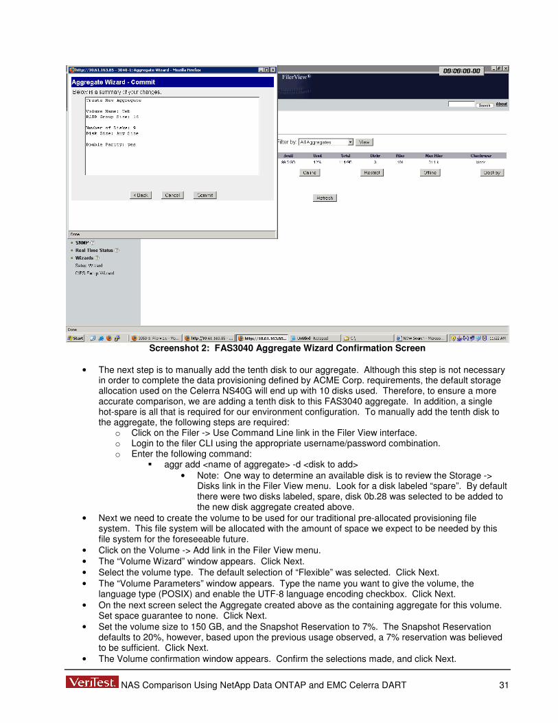
NAS Comparison Using NetApp Data ONTAP and EMC Celerra DART 31
Screenshot 2: FAS3040 Aggregate Wizard Confirmation Screen
• The next step is to manually add the tenth disk to our aggregate. Although this step is not necessary
in order to complete the data provisioning defined by ACME Corp. requirements, the default storage allocation used on the Celerra NS40G will end up with 10 disks used. Therefore, to ensure a more accurate comparison, we are adding a tenth disk to this FAS3040 aggregate. In addition, a single hot-spare is all that is required for our environment configuration. To manually add the tenth disk to the aggregate, the following steps are required:
o Click on the Filer -> Use Command Line link in the Filer View interface. o Login to the filer CLI using the appropriate username/password combination. o Enter the following command:
� aggr add <name of aggregate> -d <disk to add> • Note: One way to determine an available disk is to review the Storage ->
Disks link in the Filer View menu. Look for a disk labeled “spare”. By default there were two disks labeled, spare, disk 0b.28 was selected to be added to the new disk aggregate created above.
• Next we need to create the volume to be used for our traditional pre-allocated provisioning file system. This file system will be allocated with the amount of space we expect to be needed by this file system for the foreseeable future.
• Click on the Volume -> Add link in the Filer View menu. • The “Volume Wizard” window appears. Click Next. • Select the volume type. The default selection of “Flexible” was selected. Click Next. • The “Volume Parameters” window appears. Type the name you want to give the volume, the
language type (POSIX) and enable the UTF-8 language encoding checkbox. Click Next. • On the next screen select the Aggregate created above as the containing aggregate for this volume.
Set space guarantee to none. Click Next. • Set the volume size to 150 GB, and the Snapshot Reservation to 7%. The Snapshot Reservation
defaults to 20%, however, based upon the previous usage observed, a 7% reservation was believed to be sufficient. Click Next.
• The Volume confirmation window appears. Confirm the selections made, and click Next.

NAS Comparison Using NetApp Data ONTAP and EMC Celerra DART 32
• The next step is to configure the Snapshot Reservation Schedule. Click on the Volume -> Snapshots -> Configure link in the Filer View menu.
• Select the volume created above from the “Volume” drop-down list. The Snapshot Reservation value should show 7%. Leave the Snapshot Directory Visible and Scheduled Snapshots checkboxes checked.
• Set the Number of Scheduled Snapshots to Keep to the following values. These settings ensure that we meet our 3 day on-disk retention policy defined by the ACME Corp. requirements.
o 0 Weekly o 1 Nightly o 72 Hourly
• Check all 24 hourly snapshot options. Click the Apply button. • Next we needed to add create a CIFS share for this new volume that was created above. Click on
the CIFS -> Shares -> Add link in the Filer View menu. • The “Add a CIFS Share” window appears. Enter a name for the share, along with the appropriate
mount point, and a description (optional). The Max. Users and Force Group options can be left at their default setting. Click on the Add button.
• Next we want to create the 20 GB file system to be shared out via the NFS protocol. Click on the Volume -> Add link in the left pane.
• Click Next on the initial Volume Wizard GUI screen. • Select “Flexible” for the volume type. Click Next. • Enter the name for the volume, select POSIX for the language, and check the UTF-8 box. Click Next. • Select the proper Aggregate, and set the Space Guarantee option to “volume.” Click Next. • Set the size to be 20 GB, and Snapshot reserve to be 0%. Click Next. • Confirm the proper selections, then Click Commit. • Click on the NFS -> Manage link in the left pane. • Click on the entry for the newly created 20 GB volume. • Ensure Read-write Access, Root Access and Security boxes are checked. Click Next. • Enter the export path (e.g., /vol/Operations). Click Next. • Click Add; Enter the IP address for the Linux host, Click OK. Click Next. (Read/write permissions) • Click Add; Enter the IP address for the Linux host, Click OK. Click Next. (Root permissions). • Select “Unix Style” for security. Click Next. • Confirm selections. Click on Commit. • This completes the initial configuration process. After completing the above steps, we have added
our FAS3040 to the network with the appropriate network settings, joined it to our Windows AD Domain, provisioned our storage, configured the initial data retention (snapshot) schedule, and presented it to our CIFS network for usage by our Windows based system(s).
F. Detailed Steps for Test Case 1 with the EMC Celerra DART Solution The following steps needed to be complete on the Celerra NS40G to complete the initial device configuration:
• Launch a web browser to the IP address assigned to the Celerra NS40G. • Confirm the acceptance of the certificates associated with the Celerra NS40G, and allow the java
runtime environment to be initiated. • Login to the Celerra NS40G as the root user. To ensure we would have full access to make any
necessary changes to the device configuration, particularly any Control Station changes, we used the root account during the initial device configuration process. This environment was reset a couple times to validate our results, and as such, we needed to re-install the control station software. By logging into the Celerra NS40G Manager GUI as root, we would be able to make any changes to the configuration if required. If not logged in as root, then the Control Station options are not presented as the nasadmin account does not have sufficient privileges to modify those settings.
• Expand the menu for the Celerra NS40G IP Address listed. • Click on the “Wizards” item. • Click on the “Set Up Celerra” wizard item. • The “Set Up Celerra Wizard” window appears. Click on Next. • Enter the hostname for the device. Click Next.

NAS Comparison Using NetApp Data ONTAP and EMC Celerra DART 33
• Enter the DNS settings required. Click Next. • Enter the DNS domain search order. Click Next. • The control station NTP screen appears; enter the desired NTP IP Address information. Click Next. • Set the timezone for the control station, and set the time (if necessary). Click Next. • Enable the licenses applicable for this Celerra NS40G device. Click Next.
o Note: All licenses were checked. • The “Overview/Results” window appears. Confirm the information is accurate, and click on the
Submit button. • The next step to complete is the Data Mover setup. The GUI will default to this item. Click Next. • The data mover roles window will appear, click Next. • The set data mover role window will appear. Set server_2 as the primary and server_3 as the
standby roles for each data mover. Click Next. • The Celerra Manager Control Station will communicate with each data mover and confirm they are
online, functional. This takes a few seconds to complete. Confirm both data movers report a status of “OK”. Click Next.
• The “Unicode Enabled” screen appears. Verify the setting and click Next. • The “Select Standby DM” window will appear. Confirm server_3 is identified as the standby data
mover for server_2. Click Next. • The “Set DM Failover Policy” window appears. Verify server_2 is listed in the “Auto” section, and
click Next. • The “Set DM NTP Servers” window appears. Configure NTP server as desired, then click on Next. • The “Overview/Results” window appears. Confirm settings are accurate, and then click on Next. • The Next step is to configure the DM Network Services. The Celerra Manager GUI will default to this
item. Click Next. • Select server_2 from the data mover list (this was the default presented). Click Next. • The “DM DNS Settings” window appears. Set DNS settings as needed, and then click Next. • The “Overview/Results” screen appears. Confirm DNS settings and click on Submit. • The “DN NIS Settings” window will appear. Our environment is not using NIS, so nothing needs to be
filled out here. Click Next. • A window will appear asking if we want to setup network services for another data mover. Select the
“no” radio button, then click on Next. • We next need to setup the DM interface. The Celerra Manager GUI will default to the “Create DM
Network Interface” item. Select the “Yes” radio button, and click Next. • Again, select the server_2 data move, and click Next. • The Celerra NS40G provides 4 network interfaces onboard. For the purposes or our ACME Corp.
network, only one of the interfaces needed to be configured. We configured the cge0 interface. Select the cge0 interface, and then click on the Next button.
• Enter the IP Address, and netmask information. The broadcast IP will fill in automatically. Click Next. • Set the MTU size to be used. Click Next. • Set a VLAN ID if desired. This was not needed for our environment, so it was left empty. Click Next. • The Overview/Results window will appear. Confirm the settings listed, and then click on Submit. • We then tested the network connectivity by entering the IP address of our Windows 2003 AD server,
and pinged it. This was successful, indicating proper network configuration had occurred. Click Next. • We did not need to configure additional network interfaces, therefore, we then moved on to the next
step of creating a file system. • Again, data mover server_2 was selected as the data mover to be used for the file system creation.
Click Next. • The “Select Volume Management Type” window appears. Select “Storage Pool” and click Next. • The only backend device configured for this Celerra is a CX3-40c. This device appears automatically
in this wizard. Confirm the CLARiiON CX3-40 appears with the correct amount of storage available, and click Next. The CLARiiON reported roughly 1 TB of storage available. This is approximately 100 GB more storage available than reported on the FAS3040.
• The “Enter File System Info.” Screen appears. Enter the desired file system name, size and leave the “slice volumes” checkbox checked. Click Next.

NAS Comparison Using NetApp Data ONTAP and EMC Celerra DART 34
• The “Enable Auto Extend” window appears. Enable Auto Extend, with a high watermark of 90%. Since this file system is a traditional pre-allocated file system, we did not check the “Virtual Provisioning” option for this file system. Click Next.
• The “Default Quota Settings” window appears. We did not require Quotas to be set, so this was left at “No”. Click Next.
• The “Overview/Results” window appears. Confirm settings are accurate, and then click on Submit. • The next step is to create the CIFS share. We did not need to create another file system, so select
“No”. Click Next to move on to CIFS share setup step. • Select “Yes” to create a new CIFS share. Click Next. • The “Select CIFS Share Location” window appears. Select the radio button for “By selecting a file
system first”, and then click Next. • Again, ensure data mover server_2 is selected, and then click Next. • The “Select/Create File System” window appears. Select the “File Systems” radio button. The file
system created above will be listed. Highlight this file system, click Next. • The “Select/Create CIFS Servers” window will appear. Since there aren’t any pre-existing CIFS
servers, we need to create one. Click on the “Create CIFS Server” button. • Again select server_2 as the data mover. Click Next. • Confirm the cge0 interface created above is listed/highlighted. Click Next. • The “Select CIFS Server Type” window will appear. Select the radio button for “Windows 2000/2003”
option. Click Next. • The “Check Unicode” window will appear. This will confirm that Unicode is enabled. On the data
mover. Click Next. • The “DM DNS Settings” window appears. This reports the DNS information configured above. Verify
this reports the correct Domain and IP information for the Windows Server 2003 AD server. Click Next.
• The “NTP Settings” window will appear. Click “Add” to add the Windows Server 2003 AD server’s IP address as the NTP server. Click Next.
• The “Enter Windows Domain” window will appear. Enter the Windows Server 2003 AD Domain information, click Next.
• Enter a computer name. Click Next. • The “Enter Aliases” window appears. We did not require this option, which is optional, so this was left
empty. Click Next. • The “Enable Local Users” window appears. This was not required for our environment, so we set this
to “no”. Click Next. • The “Usermapper Servers” window appears. This is optional, and was left empty. Click Next. • The “Join Domain” window appears. Select “Yes”, click Next. • The “Enter Organization Unit” window appears. Select the radio button for “Computers: EMC
Celerra”. Click Next. • The “Enter Domain Information” window appears. Enter the Domain username/password
combination and click Next. • The “Overview/Results” window appears. Confirm information, and then click on the Submit button. • At this point we received an error message (see screenshots 3 and 4 below). We retried the
connection several times. We also verified network settings, username/password values and other configuration settings. After much trouble-shooting we determined the issue was with the complex password in place on our Windows Server 2003 AD domain server. This password was set to P4$$w0rd. We determined that the “$$” were the cause of the issue. Changing these to “SS” would allow the Celerra NS40G Manager GUI to join the domain; however, changing this password to a less secure value was not an acceptable option. Therefore, further investigation took place. We then found that we could accomplish the domain join operation, with the complex password in place, by using the Celerra CLI.

NAS Comparison Using NetApp Data ONTAP and EMC Celerra DART 35
Screenshot 3: Celerra Manager GUI Windows AD Join Error Message
Screenshot 4: Celerra Manager GUI Windows AD Join Error Message

NAS Comparison Using NetApp Data ONTAP and EMC Celerra DART 36
• The following steps were required to join the Celerra to our Windows Server 2003 AD Domain with the complex password in place:
o It is necessary to use a utility that can connect to the Celerra Control Station via the SSH protocol. From a Microsoft Windows environment this can be done by downloading the application PuTTY. Otherwise a Linux/Unix system with an SSH client installed is required to connect to the EMC Control Station CLI.
o Since our goal was to evaluate how well each storage solution integrated within a Windows Server 2003 AD domain, we downloaded PuTTY and installed it on our AD server. We then used it to connect to the Celerra Control Station CLI.
o The following two commands needed to be executed to complete the CIFS Domain Join operation:
� server_cifs server2 -add compname=cs0,domain=wudss.ppe,interface=10_61_163_84,dns=wudss.ppe
� server_cifs server2 -Join compname=cs0,domain=wudss.ppe,admin=administrator • Note: After the second command is executed, you are prompted to enter the
password for the Domain Administrator account. At this point the complex password is entered, and the Celerra is successfully joined to the Windows Server 2003 AD Domain.
• At this point we can now go back into the Celerra Manager Web GUI and complete the tasks necessary to create the CIFS share and make it available to our CIFS based network.
• In the Celerra Manager Web GUI, return to the “Select/Create CIFS Servers” window, and you will now see the cs0 CIFS server added via the CLI steps above. Select this server, and click on Next.
• The “Enter CIFS Share” window will appear. Enter the CIFS share name. A comment is optional. We did not set any user limit. Click Next.
• The “Overview/Results” window will appear. Click Submit. • The next step is to create the data retention schedule. Click on the “Checkpoints” item in the Celerra
Manager Web GUI. • Click on the “Schedules” tab. Select the server_2 data mover, and the file system created above.
Click on “New”. • The “New Schedule” window appears. Verify the proper data mover is selected. Select the proper
file system. • Configure the schedule to take hourly checkpoints, and retain 72 iterations. Screenshots 5 and 6
below show how we configured this initial checkpoint schedule.

NAS Comparison Using NetApp Data ONTAP and EMC Celerra DART 37
Screenshot 5: Celerra NS40G Hourly Checkpoint Schedule
Screenshot 6: Celerra NS40G Hourly Checkpoint Schedule

NAS Comparison Using NetApp Data ONTAP and EMC Celerra DART 38
• Enable the NFS features of the Celerra. Click on the IP address of the management station listed in the left pane.
• Click on the Licenses tab. • Check the box for NFS. Click OK. • Confirm the selection. Click OK. • Click on File Systems -> New to create the 20 GB file system to be shared out via the NFS protocol. • Enter the file system name, select the storage pool, and enter the capacity. Click OK. • Click on the NFS Exports link in the left pane. • Click on New. • Select the data mover, File system, enter the Path, and Enter the IP address of the Linux server for
the read/write Hosts and Root hosts options. Click OK. • This completes the initial configuration process. After completing the above steps, we have added
our Celerra NS40G to the network with the appropriate network settings, joined it to our Windows AD Domain, provisioned our storage, configured the initial data retention (checkpoint) schedule, and presented it to our CIFS network for usage by our Windows based system(s).
G. NFS Configuration Steps for Test Case #2 Data Staging Scripts Although NFS features were not an item specifically examined in test case 2, in order to stage data to the 150 GB pre-allocated provisioned file system, the file system needed to be shared out via NFS to allow the Linux server to NFS mount the file system. The Linux server contained the data generation staging scripts (shown in Appendix M) used to generate the data in Test Case 2. The following steps are required to configure an NFS share on the FAS3040:
• Open a web browser to the IP address assigned to the FAS3040. • Click on the na_admin link. Login with the appropriate username/password combination. • Click on the “Filer View” link • Click on the NFS -> Manage Exports in the Filer View menu. • Click on the file system to be configured to share out via NFS to the Linux client. • This will launch the “NFS Export Wizard”. • Click on the check boxes for the following options:
o Read-Write Access o Root Access o Security
• Click Next. • Enter the path to be exported. Click Next. • The “Read-Write Hosts” window appears, click on the “Add” button and enter the IP address of the
Linux client. Click the Next button. • The “Root Hosts” window appears, click on the “Add” button and enter the IP address of the Linux
client. Click the Next button. • The “Security” window appears, ensure the “Unix Style” option is selected, and click on the Next
button. • The “Commit” window appears. Verify the settings selected, and click on the Commit button. • This completes the steps necessary to properly share out the desired file system as an NFS share to
the Linux client. The following steps are required to configure an NFS share on the Celerra NS40G:
• Open a web browser to the IP address assigned to the Celerra NS40G control station. • Confirm the acceptance of the certificates associated with the Celerra NS40G, and allow the java
runtime environment to be initiated. • Login to the Celerra NS40G as the nasadmin account. • Expand the menu for the Celerra, and click on the “NFS Exports” menu item. • Click on the “New” button. • The “New NFS Export” window appears. Fill out the fields as appropriate. Refer to screenshot 1
below as an example of how to share out the file system via NFS to the Linux client:

NAS Comparison Using NetApp Data ONTAP and EMC Celerra DART 39
Screenshot 1: Celerra NS40G NFS Export Configuration Screen
• Click on the OK button to apply the changes. • This completes the steps necessary to configure a file system to be shared out via NFS to the Linux
client system.
H. Detailed Steps for Test Case #2 Date Retention Schedule Changes We used the NetApp FilerView GUI modify the existing snapshot schedule that was created as part of Test Case 1. The following steps were necessary to make the change to the existing data retention schedule:
• Login to the FilerView GUI. • Navigate the left pane as such:
o Volumes -> Snapshots -> Configure. • Select the volume from the drop-down list. • Replace “72” with “24” in the Hourly field. • Select the following values under the “Hourly Snapshot Schedule”:
o AM: 12, 3, 6, 9 o PM: 12, 3, 6, 9
• Click on Apply. We used the Celerra Manager GUI to make the changes necessary to meet the new data retention policy. The EMC solution does not allow the number of iterations to be retained to be modified after the retention schedule is created. Therefore, we had to create a new schedule containing the new retention values, and delete the previously created schedule (created as part of Test Case 1). The following steps were necessary to complete the data retention schedule modification task:
• Login to the Celerra Manager GUI as nasadmin • Click on the “Checkpoints” option in the left pane. • Click on the “Schedules” tab. • Click on the “New” button. • Enter the “Schedule Name” and optional Description.

NAS Comparison Using NetApp Data ONTAP and EMC Celerra DART 40
• Click on the “Select Hours” radio button under the “Mode to Enter Schedule Runtimes:” section. • Select the following runtimes: 00, 03, 06, 09, 12, 15, 18, 21 • Enter “24” in the “Keep” section. Click OK. • The following error message appears due to the default selection of “on the hour” for the new
checkpoint schedule. This is due to the existence of the previously configured retention schedule having already defined these hourly points as times to take a checkpoint. Modify the minutes for each checkpoint to occur at 15 minutes past the hour. Then click OK.
• • Navigate back to the Checkpoint -> Schedules location. • Delete the checkpoint schedule created in Test Case 1. • Navigate back to the Checkpoint -> Schedules location. • Right-click on the schedule, and select “Properties”. • Modify the “At Which Times:” section to have the checkpoints occur on the hour (i.e. replace :15 with
:00 for each time entry). Click OK. The goal of this section of the test case is to compare the options available and the effort required for the storage administrator to modify the existing data retention policy to more adequately handle the actual observed rate of data consumption. In this case, we changed the retention schedules as detailed below. For the NetApp solution, the 150 GB file system was extended manually to 200 GB using the Filer View GUI to ensure enough volume space existed to handle the file system data and snapshot data. This was required since the initial 24 snapshots taken were using more space than initially estimated, and we would have consumed all 150 GB of space with data and snapshots before the data staging scripts completed. The EMC solution did not require any manual intervention to increase the amount of space allocated to the production file system as checkpoint storage is contained within a separate storage allocation from the file system. . The key metrics recorded for this test case are:
• The number of steps and amount of time it takes to modify the data retention policy as defined above. • Is file system expansion required to ensure enough space is provisioned to allow the data staging to
complete successfully?

NAS Comparison Using NetApp Data ONTAP and EMC Celerra DART 41
• If the file system requires expansion, is expansion possible, and will it impact the ability of the data staging process started in test case #2 to complete successfully?
• How much space is being consumed by the initial data retention policy (point-in time retention copies)?
I. Detailed Steps for Test Case #6 with the NetApp Data ONTAP Solution • Open a web browser to the IP address of the FAS3040. • Click on the na_admin link & enter the appropriate Username/Password combination. • Click on the “Filer View” link. • Click on the “Volumes” menu item, then click on Add • You will be presented with the Volume Wizard GUI, click next. • Select “Flexible Volume” type and click next. • Give the volume a name, select POSIX as the language type and enable UTF-8 support, cli1ck next. • Choose the “Build” Aggregate containing the 10 disk aggregate created in Test Case 1. Set space
guarantee to Volume and click on next. • Set the Volume Size to 100GB and Snapshot Reserve to 5%.
o These are the expected maximum size and average rate of change estimates based on the type of data to be contained in this new volume.
• Confirm the selections set, and click on the commit button. Screenshot 7 below shows an example of the confirmation screen presented in the Filer View Volume Wizard GUI:
Screenshot 7: Filer View Volume Wizard Commit Screen
• Click on Filer -> Use Command Line in the Filer View menu. This will launch a java based interface
to the Filer CLI. • Login as root, and execute the following command:
o maxfiles devel 10640379 o Confirm the change by entering “yes” and then enter.

NAS Comparison Using NetApp Data ONTAP and EMC Celerra DART 42
• Click on CIFS -> Shares -> Add in the Filer View menu. • Enter the CIFS share name and mount point. Give a description of this new share. Leave the Max.
Users and Force Group fields at default settings. Click on the Add button. • With the NetApp solution we can now reduce the size of the Devel volume to 10GB to match what the
starting point will be on the EMC solution. The following steps were taken to accomplish this: o Click on Volume -> Manage -> Devel in the Filer View GUI. o Click on the “Resize Storage” button. This will open the Volume Wizard interface. o The only setting requiring change is the Volume Size. Set this to 10GB and Commit the
change. The NetApp solution will now resize the volume from 100GB to 10GB. o Next click on the Filer -> Use Command Line in the Filer View GUI. o Login to the CLI and execute the following commands:
� options Devel fractional_reserve 0 � vol autosize Devel 100g –I 10g on � snap autodelete Devel on � snap autodelete Devel commitment try � snap autodelete Devel trigger volume � snap autodelete Devel target_free_space 1 � vol options Devel try_first volume_grow
• This concludes the steps necessary to configure a Thin Provisioned volume on the NetApp solution. • At this point the new volume is ready to be used and available for CIFS access. To load the data
from the Linux host we needed to also setup NFS access. This was done also via the Filer View GUI. Please refer to Appendix G for details on now NFS was configured.
J. Detailed Steps for Test Case #6 with the EMC Celerra DART Solution • Launch a web browser to the IP address assigned to the Celerra NS40G. • Confirm the acceptance of the certificates associated with the Celerra NS40G, and allow the java
runtime environment to be initiated. • Login to the Celerra NS40G as the nasadmin account. • Expand the menu for the Celerra, and click on the “File Systems” item. • Click on the “New” button to create the new Virtual Provisioned based file system. • On the “New File System” screen, set the following values as exampled by screenshot 8 below:

NAS Comparison Using NetApp Data ONTAP and EMC Celerra DART 43
Screenshot 8: Virtual Provisioned File System Settings
• Click on the OK button to create the new file system. • Right-click on the new file system, select Checkpoints -> New Schedule • Create a new schedule for this file system with the following values as shown in Screenshots 9 and
10 below:

NAS Comparison Using NetApp Data ONTAP and EMC Celerra DART 44
Screenshot 9: Virtual Provisioned File System Checkpoint Schedule Settings
Screenshot 10: Virtual Provisioned File System Checkpoint Schedule Settings

NAS Comparison Using NetApp Data ONTAP and EMC Celerra DART 45
• Click on the OK button to apply the changes. • Next, click on the CIFS menu item, and then the “New” button to create the CIFS share for this new
file system. • Refer to screenshot 11 below for the settings used to configure the CIFS share:
Screenshot 11: Virtual Provisioned File System CIFS Share Settings
• Click on the “OK” button to apply the changes. • At this point the new volume is ready to be used and available for CIFS access. To load the data
from the Linux host we needed to also setup NFS access. This was done also via the Celerra Web Management GUI. Please refer to Appendix G for details on now NFS was configured.
K. Detailed Steps for Test Case #7 with the NetApp Data ONTAP Solution • Confirm the setting to map Administrator to Root is off for the Filer:
o options wafl.nt_admin_priv_map_to_root off • Confirm the default settings are as listed:
o options wafl.default_security_style unix o options wafl.default_unix_user pcuser
• Enable the following Options by setting them to ON o options cifs.perm_check_use_gid on o options cifs.preserve_unix_security on
• Create a new FlexVol called Shared (20 GB size) • Create 2 Qtrees under the Shared volume
o First Qtree will be called Unix. Set with “unix” security style. o Second Qtree will be called Windows. Set with “ntfs” security style.
• Create NFS export for Shared: r/w, root = 10.61.163.31 • Create CIFS export for Shared: 10.61.163.30 • Create NFS export for /vol/Shared/Unix qtree: r/w, root=10.61.163.31 • Create CIFS export /vol/Shared/Windows qtree: 10.61.163.30

NAS Comparison Using NetApp Data ONTAP and EMC Celerra DART 46
• Login to the Linux client. • Mount the “Shared” NFS export onto the Linux host:
o mkdir /mnt/netapp/Shared o mount 10.61.163.85:/vol/Shared /mnt/netapp/Shared
• Run the following command: o for num in 1 2 3 4 5 6 7 8 9 0; do dd if=/dev/urandom of=/mnt/netapp/Shared/unixfile.${num}
bs=32768 count=3200; done � The above command will create 10 * 100 MB files.
• Mount the “Unix” NFS export onto the Linux host: o Mkdir /mnt/netapp/Unix o Mount 10.61.163.85:/vol/Shared/Unix /mnt/netapp/Unix
• Run the following command: o for num in 1 2 3 4 5 6 7 8 9 0; do dd if=/dev/urandom of=/mnt/netapp/Unix/unixfile.${num}
bs=32768 count=3200; done � The above command will create 10 * 100 MB files. � {Chmod 770 .} for the Unix Qtree <this prevents the other group from having any
browse access > It is assumed in this config that all users form unix will be a member of the same group or related group of the file owners
• Attempt to access the Windows qtree folder under the /mnt/netapp/Shared path. �-This should fail. o This did fail as expected for non-NT accounts.
• Login to the Windows client. • Map the Shared CIFS export from the Windows host. • Use Folder Maker Pro (FMK) to create 1000 * 1 MB files. • Map the Windows CIFS export from the Windows host. • Use Folder Maker Pro (FMK) to create 1000 * 1 MB file. • Take a snapshot of the Shared volume. • Record storage utilization.
L. Detailed Steps for Test Case #7 with the EMC Celerra DART Solution o Record storage utilization. o Confirm the setting to map Administrator to Root is off for the node:
� GUI: Data Mover -> Parameters
• cifs.admin.adminAsRoot = 0 (default is 1) o Create a new "Shared” 10 GB File system.
� Use default Access Policy. o Create a new file system called: Windows (5 GB)
� Set with “NT” Access Policy. o Create a new file system called: Unix (5 GB)
� Set with “Unix” Access Policy. o Create NFS export for Shared: r/w,root=10.61.163.31 o Create a CIFS export for Shared: 10.61.163.30 o Create NFS export for Unix: r/w,root=10.61.163.31 o Create CIFS export for Windows: 10.61.163.30 o Login to the Linux client. o Mount the NFS export from the Linux host:
� mkdir /mnt/Shared � mount 10.61.163.84:/Shared /mnt/emc/Shared
o Run the following command: � for num in 1 2 3 4 5 6 7 8 9 0; do dd if=/dev/urandom
of=/mnt/emc/Shared/unixfile.${num} bs=32768 count=3200; done • The above command will create 10 * 100 MB files.
o Mount the “Unix” NFS export onto the Linux host: � Mkdir /mnt/emc/Unix � Mount 10.61.163.84:/Unix /mnt/emc/Unix
o Run the following command:

NAS Comparison Using NetApp Data ONTAP and EMC Celerra DART 47
� for num in 1 2 3 4 5 6 7 8 9 0; do dd if=/dev/urandom of=/mnt/emc/Unix/unixfile.${num} bs=32768 count=3200; done
• The above command will create 10 * 100 MB files. • {Chmod 770 .} for the Unix Qtree <this prevents the other group from having
any browse access > It is assumed in this config that all users form unix will be a member of the same group or related group of the file owners
o Login to the Windows client. o Map the Shared CIFS export from the Windows host. o Use Folder Maker Pro (FMK) to create 1000 * 1 MB files. o Map the Windows CIFS export from the Windows host. o Use Folder Maker Pro (FMK) to create 1000 * 1 MB file. o Take a checkpoint of each file system. o Record storage utilization.
M. Test Case #2 Data Staging Scripts • Traditional Provisioning files for the data staging scripts:
o Build Script #!/bin/bash
var0=1
LIMIT=60
mkdir Application
cd Application
while [ "$var0" -lt "$LIMIT" ]
do
mkdir "$var0";
cd $var0;
for i in $(seq 1 8192);
do mkdir "${i}";
cd "$i";
dd if=/dev/urandom of=a bs=4096 count=1 > /dev/null 2>&1;
mkdir "${i}";
cd "$i";
dd if=/dev/urandom of=a bs=4096 count=1 > /dev/null 2>&1;
mkdir "${i}";
cd "$i";
dd if=/dev/urandom of=a bs=4096 count=1 > /dev/null
2>&1;
cd ..;
cd ..;
cd ..;
done
cd ..;
var0=$((var0 + 1));
echo "$var0";
date;
echo "sleeping 5 minutes";
sleep 300;
done
o Directory 1 Script: #!/bin/bash
var0=1
LIMIT=60
while [ "$var0" -lt "$LIMIT" ]
do
cd $var0;
for i in $(seq 1 8192);
do cd "$i";
dd if=/dev/urandom of=123456789a bs=3096 count=1 > /dev/null 2>&1;
dd if=/dev/urandom of=123456789b bs=3096 count=1 > /dev/null 2>&1;
dd if=/dev/urandom of=123456789c bs=3096 count=1 > /dev/null 2>&1;
dd if=/dev/urandom of=123456789d bs=3096 count=1 > /dev/null 2>&1;
dd if=/dev/urandom of=123456789e bs=3096 count=1 > /dev/null 2>&1;
dd if=/dev/urandom of=123456789f bs=3096 count=1 > /dev/null 2>&1;

NAS Comparison Using NetApp Data ONTAP and EMC Celerra DART 48
dd if=/dev/urandom of=123456789g bs=3096 count=1 > /dev/null 2>&1;
dd if=/dev/urandom of=123456789h bs=3096 count=1 > /dev/null 2>&1;
dd if=/dev/urandom of=123456789i bs=3096 count=1 > /dev/null 2>&1;
dd if=/dev/urandom of=123456789j bs=3096 count=1 > /dev/null 2>&1;
dd if=/dev/urandom of=123456789k bs=3096 count=1 > /dev/null 2>&1;
dd if=/dev/urandom of=123456789l bs=3096 count=1 > /dev/null 2>&1;
dd if=/dev/urandom of=123456789m bs=3096 count=1 > /dev/null 2>&1;
dd if=/dev/urandom of=123456789n bs=3096 count=1 > /dev/null 2>&1;
dd if=/dev/urandom of=123456789o bs=3096 count=1 > /dev/null 2>&1;
dd if=/dev/urandom of=123456789p bs=3096 count=1 > /dev/null 2>&1;
dd if=/dev/urandom of=123456789q bs=3096 count=1 > /dev/null 2>&1;
dd if=/dev/urandom of=123456789r bs=3096 count=1 > /dev/null 2>&1;
dd if=/dev/urandom of=123456789s bs=3096 count=1 > /dev/null 2>&1;
dd if=/dev/urandom of=123456789t bs=3096 count=1 > /dev/null 2>&1;
dd if=/dev/urandom of=123456789u bs=3096 count=1 > /dev/null 2>&1;
dd if=/dev/urandom of=123456789v bs=3096 count=1 > /dev/null 2>&1;
dd if=/dev/urandom of=123456789w bs=3096 count=1 > /dev/null 2>&1;
dd if=/dev/urandom of=123456789x bs=3096 count=1 > /dev/null 2>&1;
cd ..;
done
cd ..;
Del0=$((var0 - 13));
if [ "$Del0" -ge "1" ]; then
rm -rf "$Del0";
echo "$Del0";
date;
echo "deletion complete sleep 2 min";
sleep 120;
fi
var0=$((var0 + 1));
echo "$var0";
date;
echo "sleeping 10 minutes";
sleep 480;
done
o Directory 2 Script: #!/bin/bash
var0=1
LIMIT=60
while [ "$var0" -lt "$LIMIT" ]
do
cd $var0;
for i in $(seq 1 8192);
do cd "$i";
cd "$i";
dd if=/dev/urandom of=123456789a bs=4096 count=1 > /dev/null 2>&1;
dd if=/dev/urandom of=123456789b bs=4096 count=1 > /dev/null 2>&1;
dd if=/dev/urandom of=123456789c bs=4096 count=1 > /dev/null 2>&1;
dd if=/dev/urandom of=123456789d bs=4096 count=1 > /dev/null 2>&1;
dd if=/dev/urandom of=123456789e bs=4096 count=1 > /dev/null 2>&1;
dd if=/dev/urandom of=123456789f bs=4096 count=1 > /dev/null 2>&1;
dd if=/dev/urandom of=123456789g bs=4096 count=1 > /dev/null 2>&1;
dd if=/dev/urandom of=123456789h bs=4096 count=1 > /dev/null 2>&1;
dd if=/dev/urandom of=123456789i bs=4096 count=1 > /dev/null 2>&1;
dd if=/dev/urandom of=123456789j bs=4096 count=1 > /dev/null 2>&1;
dd if=/dev/urandom of=123456789k bs=4096 count=1 > /dev/null 2>&1;
dd if=/dev/urandom of=123456789l bs=4096 count=1 > /dev/null 2>&1;
dd if=/dev/urandom of=123456789m bs=4096 count=1 > /dev/null 2>&1;
dd if=/dev/urandom of=123456789n bs=4096 count=1 > /dev/null 2>&1;
dd if=/dev/urandom of=123456789o bs=4096 count=1 > /dev/null 2>&1;
dd if=/dev/urandom of=123456789p bs=4096 count=1 > /dev/null 2>&1;
dd if=/dev/urandom of=123456789q bs=4096 count=1 > /dev/null 2>&1;
dd if=/dev/urandom of=123456789r bs=4096 count=1 > /dev/null 2>&1;
dd if=/dev/urandom of=123456789s bs=4096 count=1 > /dev/null 2>&1;
dd if=/dev/urandom of=123456789t bs=4096 count=1 > /dev/null 2>&1;
dd if=/dev/urandom of=123456789u bs=4096 count=1 > /dev/null 2>&1;
dd if=/dev/urandom of=123456789v bs=4096 count=1 > /dev/null 2>&1;
dd if=/dev/urandom of=123456789w bs=4096 count=1 > /dev/null 2>&1;
dd if=/dev/urandom of=123456789x bs=4096 count=1 > /dev/null 2>&1;
cd ..;
cd ..;

NAS Comparison Using NetApp Data ONTAP and EMC Celerra DART 49
done
cd ..;
var0=$((var0 + 1));
echo "$var0";
date;
done
o Directory 3 Script #!/bin/bash
var0=1
LIMIT=60
while [ "$var0" -lt "$LIMIT" ]
do
cd $var0;
for i in $(seq 1 8192);
do cd "$i";
cd "$i";
cd "$i";
dd if=/dev/urandom of=123456789a bs=4096 count=1 > /dev/null 2>&1;
dd if=/dev/urandom of=123456789b bs=4096 count=1 > /dev/null 2>&1;
dd if=/dev/urandom of=123456789c bs=4096 count=1 > /dev/null 2>&1;
dd if=/dev/urandom of=123456789d bs=4096 count=1 > /dev/null 2>&1;
dd if=/dev/urandom of=123456789e bs=4096 count=1 > /dev/null 2>&1;
dd if=/dev/urandom of=123456789f bs=4096 count=1 > /dev/null 2>&1;
dd if=/dev/urandom of=123456789g bs=4096 count=1 > /dev/null 2>&1;
dd if=/dev/urandom of=123456789h bs=4096 count=1 > /dev/null 2>&1;
dd if=/dev/urandom of=123456789i bs=4096 count=1 > /dev/null 2>&1;
dd if=/dev/urandom of=123456789j bs=4096 count=1 > /dev/null 2>&1;
dd if=/dev/urandom of=123456789k bs=4096 count=1 > /dev/null 2>&1;
dd if=/dev/urandom of=123456789l bs=4096 count=1 > /dev/null 2>&1;
dd if=/dev/urandom of=123456789m bs=4096 count=1 > /dev/null 2>&1;
dd if=/dev/urandom of=123456789n bs=4096 count=1 > /dev/null 2>&1;
dd if=/dev/urandom of=123456789o bs=4096 count=1 > /dev/null 2>&1;
dd if=/dev/urandom of=123456789p bs=4096 count=1 > /dev/null 2>&1;
dd if=/dev/urandom of=123456789q bs=4096 count=1 > /dev/null 2>&1;
dd if=/dev/urandom of=123456789r bs=4096 count=1 > /dev/null 2>&1;
dd if=/dev/urandom of=123456789s bs=4096 count=1 > /dev/null 2>&1;
dd if=/dev/urandom of=123456789t bs=4096 count=1 > /dev/null 2>&1;
dd if=/dev/urandom of=123456789u bs=4096 count=1 > /dev/null 2>&1;
dd if=/dev/urandom of=123456789v bs=4096 count=1 > /dev/null 2>&1;
dd if=/dev/urandom of=123456789w bs=4096 count=1 > /dev/null 2>&1;
dd if=/dev/urandom of=123456789x bs=4096 count=1 > /dev/null 2>&1;
cd ..;
cd ..;
cd ..;
done
cd ..;
var0=$((var0 + 1));
echo "$var0";
date;
done
N. Test Case #6 Data Staging Scripts • Thin Provisioning Exercise Development file system data staging scripts:
o Build Script: #!/bin/bash
var0=1
LIMIT=8
mkdir Application
cd Application
while [ "$var0" -lt "$LIMIT" ]
do
mkdir "$var0";
cd $var0;
for i in $(seq 1 8192);
do mkdir "${i}";
cd "$i";
dd if=/dev/urandom of=a bs=4096 count=1 > /dev/null 2>&1;
mkdir "${i}";

NAS Comparison Using NetApp Data ONTAP and EMC Celerra DART 50
cd "$i";
dd if=/dev/urandom of=a bs=4096 count=1 > /dev/null 2>&1;
mkdir "${i}";
cd "$i";
dd if=/dev/urandom of=a bs=4096 count=1 > /dev/null
2>&1;
cd ..;
cd ..;
cd ..;
done
cd ..;
var0=$((var0 + 1));
echo "$var0";
date;
#echo "sleeping 5 minutes";
#sleep 300;
done
o Directory 1 Script: #!/bin/bash
var0=1
LIMIT=8
while [ "$var0" -lt "$LIMIT" ]
do
cd $var0;
for i in $(seq 1 8192);
do cd "$i";
dd if=/dev/urandom of=123456789a bs=4096 count=1 > /dev/null 2>&1;
dd if=/dev/urandom of=123456789b bs=4096 count=1 > /dev/null 2>&1;
dd if=/dev/urandom of=123456789c bs=4096 count=1 > /dev/null 2>&1;
dd if=/dev/urandom of=123456789d bs=4096 count=1 > /dev/null 2>&1;
dd if=/dev/urandom of=123456789e bs=4096 count=1 > /dev/null 2>&1;
dd if=/dev/urandom of=123456789f bs=4096 count=1 > /dev/null 2>&1;
dd if=/dev/urandom of=123456789g bs=4096 count=1 > /dev/null 2>&1;
dd if=/dev/urandom of=123456789h bs=4096 count=1 > /dev/null 2>&1;
dd if=/dev/urandom of=123456789i bs=4096 count=1 > /dev/null 2>&1;
dd if=/dev/urandom of=123456789j bs=4096 count=1 > /dev/null 2>&1;
dd if=/dev/urandom of=123456789k bs=4096 count=1 > /dev/null 2>&1;
dd if=/dev/urandom of=123456789l bs=4096 count=1 > /dev/null 2>&1;
dd if=/dev/urandom of=123456789m bs=4096 count=1 > /dev/null 2>&1;
dd if=/dev/urandom of=123456789n bs=4096 count=1 > /dev/null 2>&1;
dd if=/dev/urandom of=123456789o bs=4096 count=1 > /dev/null 2>&1;
dd if=/dev/urandom of=123456789p bs=4096 count=1 > /dev/null 2>&1;
dd if=/dev/urandom of=123456789q bs=4096 count=1 > /dev/null 2>&1;
dd if=/dev/urandom of=123456789r bs=4096 count=1 > /dev/null 2>&1;
dd if=/dev/urandom of=123456789s bs=4096 count=1 > /dev/null 2>&1;
dd if=/dev/urandom of=123456789t bs=4096 count=1 > /dev/null 2>&1;
dd if=/dev/urandom of=123456789u bs=4096 count=1 > /dev/null 2>&1;
dd if=/dev/urandom of=123456789v bs=4096 count=1 > /dev/null 2>&1;
dd if=/dev/urandom of=123456789w bs=4096 count=1 > /dev/null 2>&1;
dd if=/dev/urandom of=123456789x bs=4096 count=1 > /dev/null 2>&1;
cd ..;
done
cd ..;
Del0=$((var0 - 5));
if [ "$Del0" -ge "1" ]; then
rm -rf "$Del0";
echo "$Del0";
echo "deleting directory";
date;
sleep 150;
fi
var0=$((var0 + 1));
echo "$var0";
date;
#echo "sleeping 5 minutes";
#sleep 150;
done
o Directory 2 Script: #!/bin/bash
var0=1
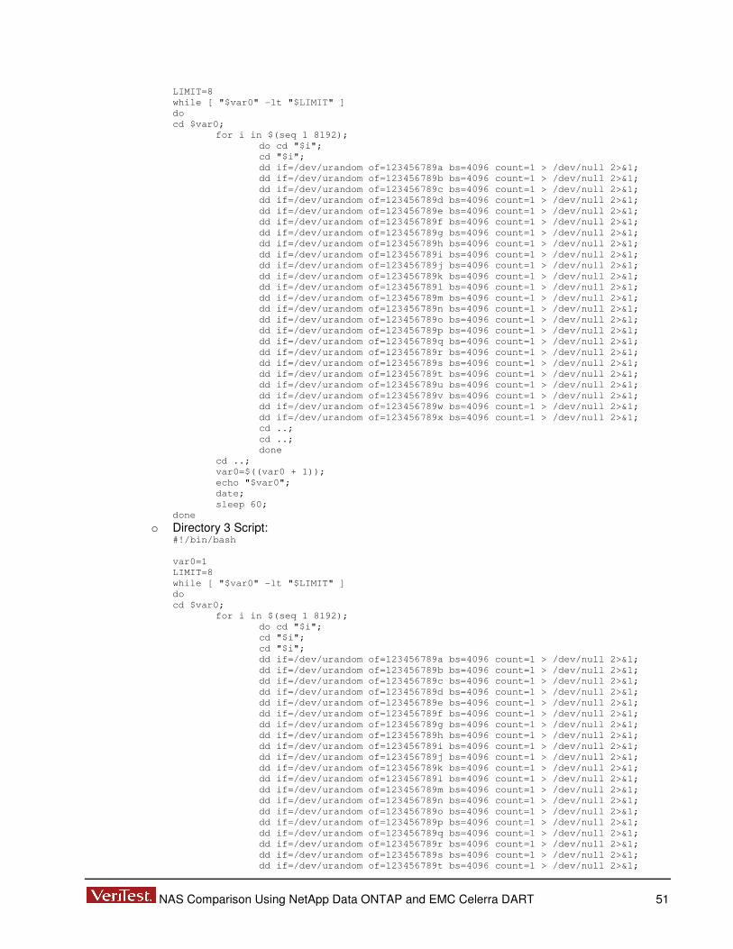
NAS Comparison Using NetApp Data ONTAP and EMC Celerra DART 51
LIMIT=8
while [ "$var0" -lt "$LIMIT" ]
do
cd $var0;
for i in $(seq 1 8192);
do cd "$i";
cd "$i";
dd if=/dev/urandom of=123456789a bs=4096 count=1 > /dev/null 2>&1;
dd if=/dev/urandom of=123456789b bs=4096 count=1 > /dev/null 2>&1;
dd if=/dev/urandom of=123456789c bs=4096 count=1 > /dev/null 2>&1;
dd if=/dev/urandom of=123456789d bs=4096 count=1 > /dev/null 2>&1;
dd if=/dev/urandom of=123456789e bs=4096 count=1 > /dev/null 2>&1;
dd if=/dev/urandom of=123456789f bs=4096 count=1 > /dev/null 2>&1;
dd if=/dev/urandom of=123456789g bs=4096 count=1 > /dev/null 2>&1;
dd if=/dev/urandom of=123456789h bs=4096 count=1 > /dev/null 2>&1;
dd if=/dev/urandom of=123456789i bs=4096 count=1 > /dev/null 2>&1;
dd if=/dev/urandom of=123456789j bs=4096 count=1 > /dev/null 2>&1;
dd if=/dev/urandom of=123456789k bs=4096 count=1 > /dev/null 2>&1;
dd if=/dev/urandom of=123456789l bs=4096 count=1 > /dev/null 2>&1;
dd if=/dev/urandom of=123456789m bs=4096 count=1 > /dev/null 2>&1;
dd if=/dev/urandom of=123456789n bs=4096 count=1 > /dev/null 2>&1;
dd if=/dev/urandom of=123456789o bs=4096 count=1 > /dev/null 2>&1;
dd if=/dev/urandom of=123456789p bs=4096 count=1 > /dev/null 2>&1;
dd if=/dev/urandom of=123456789q bs=4096 count=1 > /dev/null 2>&1;
dd if=/dev/urandom of=123456789r bs=4096 count=1 > /dev/null 2>&1;
dd if=/dev/urandom of=123456789s bs=4096 count=1 > /dev/null 2>&1;
dd if=/dev/urandom of=123456789t bs=4096 count=1 > /dev/null 2>&1;
dd if=/dev/urandom of=123456789u bs=4096 count=1 > /dev/null 2>&1;
dd if=/dev/urandom of=123456789v bs=4096 count=1 > /dev/null 2>&1;
dd if=/dev/urandom of=123456789w bs=4096 count=1 > /dev/null 2>&1;
dd if=/dev/urandom of=123456789x bs=4096 count=1 > /dev/null 2>&1;
cd ..;
cd ..;
done
cd ..;
var0=$((var0 + 1));
echo "$var0";
date;
sleep 60;
done
o Directory 3 Script: #!/bin/bash
var0=1
LIMIT=8
while [ "$var0" -lt "$LIMIT" ]
do
cd $var0;
for i in $(seq 1 8192);
do cd "$i";
cd "$i";
cd "$i";
dd if=/dev/urandom of=123456789a bs=4096 count=1 > /dev/null 2>&1;
dd if=/dev/urandom of=123456789b bs=4096 count=1 > /dev/null 2>&1;
dd if=/dev/urandom of=123456789c bs=4096 count=1 > /dev/null 2>&1;
dd if=/dev/urandom of=123456789d bs=4096 count=1 > /dev/null 2>&1;
dd if=/dev/urandom of=123456789e bs=4096 count=1 > /dev/null 2>&1;
dd if=/dev/urandom of=123456789f bs=4096 count=1 > /dev/null 2>&1;
dd if=/dev/urandom of=123456789g bs=4096 count=1 > /dev/null 2>&1;
dd if=/dev/urandom of=123456789h bs=4096 count=1 > /dev/null 2>&1;
dd if=/dev/urandom of=123456789i bs=4096 count=1 > /dev/null 2>&1;
dd if=/dev/urandom of=123456789j bs=4096 count=1 > /dev/null 2>&1;
dd if=/dev/urandom of=123456789k bs=4096 count=1 > /dev/null 2>&1;
dd if=/dev/urandom of=123456789l bs=4096 count=1 > /dev/null 2>&1;
dd if=/dev/urandom of=123456789m bs=4096 count=1 > /dev/null 2>&1;
dd if=/dev/urandom of=123456789n bs=4096 count=1 > /dev/null 2>&1;
dd if=/dev/urandom of=123456789o bs=4096 count=1 > /dev/null 2>&1;
dd if=/dev/urandom of=123456789p bs=4096 count=1 > /dev/null 2>&1;
dd if=/dev/urandom of=123456789q bs=4096 count=1 > /dev/null 2>&1;
dd if=/dev/urandom of=123456789r bs=4096 count=1 > /dev/null 2>&1;
dd if=/dev/urandom of=123456789s bs=4096 count=1 > /dev/null 2>&1;
dd if=/dev/urandom of=123456789t bs=4096 count=1 > /dev/null 2>&1;
NAS Comparison Using NetApp Data ONTAP and EMC Celerra DART 52
dd if=/dev/urandom of=123456789u bs=4096 count=1 > /dev/null 2>&1;
dd if=/dev/urandom of=123456789v bs=4096 count=1 > /dev/null 2>&1;
dd if=/dev/urandom of=123456789w bs=4096 count=1 > /dev/null 2>&1;
dd if=/dev/urandom of=123456789x bs=4096 count=1 > /dev/null 2>&1;
cd ..;
cd ..;
cd ..;
done
cd ..;
var0=$((var0 + 1));
echo "$var0";
date;
sleep 60;
done

NAS Comparison Using NetApp Data ONTAP and EMC Celerra DART 53
Windows and Microsoft are registered trademarks of Microsoft Corporation. UNIX is a registered trademark of The Open Group. Linux is a registered trademark of Linus Torvalds. All brands or products referred to in this report are trademarks or registered trademarks of their respective holders and should be treated as such.
VeriTest (www.veritest.com), the testing service of Lionbridge Technologies, Inc., provides outsourced testing solutions that maximize revenue and reduce costs for our clients. For companies who use high-tech products as well as those who produce them, smoothly functioning technology is essential to business success. VeriTest helps our clients identify and correct technology problems in their products and in their line of business applications by providing the widest range of testing services available.
VeriTest created the suite of industry-standard benchmark software that includes WebBench, NetBench, Winstone, and WinBench. We've distributed over 20 million copies of these tools, which are in use at every one of the 2001 Fortune 100 companies. Our Internet BenchMark service provides the definitive ratings for Internet Service Providers in the US, Canada, and the UK.
Under our former names of ZD Labs and eTesting Labs, and as part of VeriTest since July of 2002, we have delivered rigorous, objective, independent testing and analysis for over a decade. With the most knowledgeable staff in the business, testing facilities around the world, and almost 1,600 dedicated network PCs, VeriTest offers our clients the expertise and equipment necessary to meet all their testing needs.
For more information email us at [email protected] or call us at 919-380-2800.
Disclaimer of Warranties; Limitation of Liability: VERITEST HAS MADE REASONABLE EFFORTS TO ENSURE THE ACCURACY AND VALIDITY OF ITS TESTING, HOWEVER, VERITEST SPECIFICALLY DISCLAIMS ANY WARRANTY, EXPRESSED OR IMPLIED, RELATING TO THE TEST RESULTS AND ANALYSIS, THEIR ACCURACY, COMPLETENESS OR QUALITY, INCLUDING ANY IMPLIED WARRANTY OF FITNESS FOR ANY PARTICULAR PURPOSE. ALL PERSONS OR ENTITIES RELYING ON THE RESULTS OF ANY TESTING DO SO AT THEIR OWN RISK, AND AGREE THAT VERITEST, ITS EMPLOYEES AND ITS SUBCONTRACTORS SHALL HAVE NO LIABILITY WHATSOEVER FROM ANY CLAIM OF LOSS OR DAMAGE ON ACCOUNT OF ANY ALLEGED ERROR OR DEFECT IN ANY TESTING PROCEDURE OR RESULT. IN NO EVENT SHALL VERITEST BE LIABLE FOR INDIRECT, SPECIAL, INCIDENTAL, OR CONSEQUENTIAL DAMAGES IN CONNECTION WITH ITS TESTING, EVEN IF ADVISED OF THE POSSIBILITY OF SUCH DAMAGES. IN NO EVENT SHALL VERITEST'S LIABILITY, INCLUDING FOR DIRECT DAMAGES, EXCEED THE AMOUNTS PAID IN CONNECTION WITH VERITEST'S TESTING. CUSTOMER’S SOLE AND EXCLUSIVE REMEDIES ARE AS SET FORTH HEREIN.