Embed Size (px)
Citation preview
TD04005001E For more information visit:
www.EatonElectrical.com
LCX9000 Liquid Cooled Adjustable Frequency
Drive
Technical Data
November 2005New Information
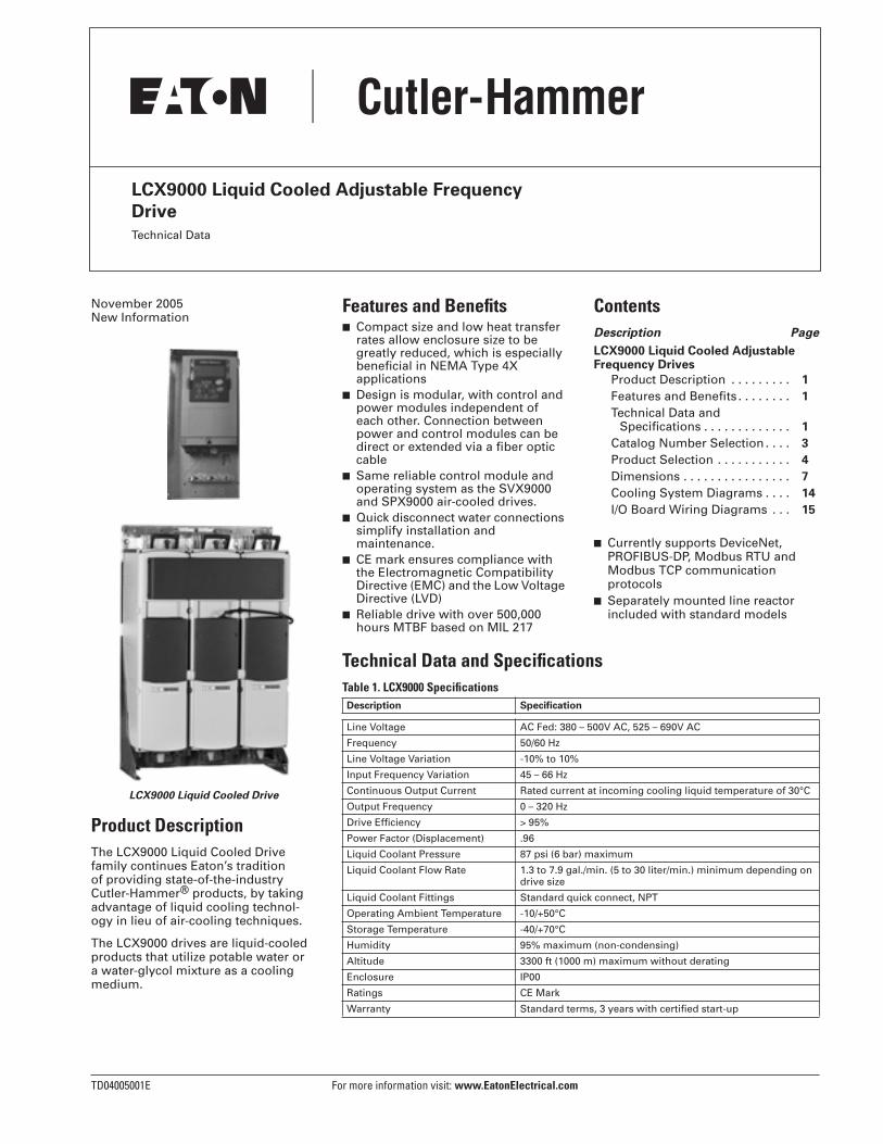
LCX9000 Liquid Cooled Drive
Product Description
The LCX9000 Liquid Cooled Drive family continues Eaton’s tradition of providing state-of-the-industry Cutler-Hammer
®
products, by taking advantage of liquid cooling technol-ogy in lieu of air-cooling techniques.
The LCX9000 drives are liquid-cooled products that utilize potable water or a water-glycol mixture as a cooling medium.
Features and Benefits
■
Compact size and low heat transfer rates allow enclosure size to be greatly reduced, which is especially beneficial in NEMA Type 4X applications
■
Design is modular, with control and power modules independent of each other. Connection between power and control modules can be direct or extended via a fiber optic cable
■
Same reliable control module and operating system as the SVX9000 and SPX9000 air-cooled drives.
■
Quick disconnect water connections simplify installation andmaintenance.
■
CE mark ensures compliance with the Electromagnetic Compatibility Directive (EMC) and the Low Voltage Directive (LVD)
■
Reliable drive with over 500,000 hours MTBF based on MIL 217
Contents
Description Page
LCX9000 Liquid Cooled Adjustable Frequency Drives
Product Description . . . . . . . . .
1
Features and Benefits . . . . . . . .
1
Technical Data andSpecifications . . . . . . . . . . . . .
1
Catalog Number Selection . . . .
3
Product Selection . . . . . . . . . . .
4
Dimensions . . . . . . . . . . . . . . . .
7
Cooling System Diagrams . . . .
14
I/O Board Wiring Diagrams . . .
15
■
Currently supports DeviceNet, PROFIBUS-DP, Modbus RTU and Modbus TCP communication protocols
■
Separately mounted line reactor included with standard models
Technical Data and Specifications
Table 1. LCX9000 Specifications
Description Specification
Line Voltage AC Fed: 380 – 500V AC, 525 – 690V AC
Frequency 50/60 Hz
Line Voltage Variation -10% to 10%
Input Frequency Variation 45 – 66 Hz
Continuous Output Current Rated current at incoming cooling liquid temperature of 30°C
Output Frequency 0 – 320 Hz
Drive Efficiency > 95%
Power Factor (Displacement) .96
Liquid Coolant Pressure 87 psi (6 bar) maximum
Liquid Coolant Flow Rate 1.3 to 7.9 gal./min. (5 to 30 liter/min.) minimum depending on drive size
Liquid Coolant Fittings Standard quick connect, NPT
Operating Ambient Temperature -10/+50°C
Storage Temperature -40/+70°C
Humidity 95% maximum (non-condensing)
Altitude 3300 ft (1000 m) maximum without derating
Enclosure IP00
Ratings CE Mark
Warranty Standard terms, 3 years with certified start-up
For more information visit:
www.EatonElectrical.com
TD04005001E
Technical Data
Page
2
Effective: November 2005
LCX9000 Liquid Cooled Adjustable Frequency Drive
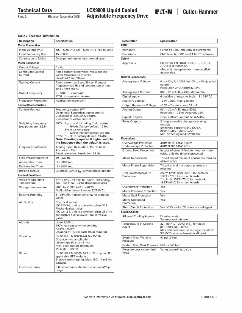
Table 2. Technical Information
Description Specification
Mains Connection
Input Voltage (Vin) 400 – 500V AC; 525 – 690V AC (-10% to 10%)
Input Frequency (fin) 45 – 66Hz
Connection to Mains Once per minute or less (normal case)
Motor Connection
Output Voltage 0 – VinContinuous OutputCurrent
Rated current at nominal inflow cooling water temperature of 30°C;Overload 2 sec./20 sec.
Starting Current Rated current at 2 sec./20 sec. if outputfrequency <30 Hz and temperature of heat-sink <149°F (65°C)
Output Frequency 0 – 320 Hz (standard);7200 Hz (special software)
Frequency Resolution Application dependent
Control Characteristics
Control Method Frequency control (V/f)Open loop: Sensorless vector controlClosed loop: Frequency control Closed loop: Vector control
Switching Frequency(see parameter 2.6.9)
480V: Up to and including 61-Amp size:1 – 16 kHz (factory default, 10 kHz)From 72-Amp size:1 – 12 kHz (factory default, 3.6 kHz)
575V: 1 – 6kHz (factory default, 1.5kHz)
Note: Derating required if higher switch-ing frequency than the default is used.
Frequency Reference Analog input: Resolution .1% (10 bits);Accuracy ± 1%Panel reference: Resolution .01 Hz
Field Weakening Point 30 – 320 Hz
Acceleration Time .1 – 3000 sec.
Deceleration Time .1 – 3000 sec.
Braking Torque DC brake: 30% x Tn (without brake option)
Ambient Conditions
Ambient Operating Temperature
14°F (-10°C), no frost to +122°F (+50°C) at Ith122 – 158°F (50 – 70°C), derating required
Storage Temperature -40°F to +158°F (-40 to +70°C)No liquid in heatsink under 32°F (0°C)
Relative Humidity 5 – 96% RH, noncondensing, no dripping water
Air Quality Chemical vapors:IEC 721-3-3, unit in operation, class 3C2Mechanical particles:IEC 721-3-3, unit in operation, class 3S2 (no conductive dust allowed); No corrosive gases
Altitude Up to 1,000m:100% load capacity (no derating)Above 1,000m:Derating of 1% per each 100m required
Vibration EN 50178, EN 60068-2-6; 5 – 150 HzDisplacement amplitude:.25 mm (peak) at 3 – 31 HzMax. acceleration amplitude:1G at 31 – 150 Hz
Shock EN 50178, EN 60068-2-27, UPS drop test (for applicable UPS weights)Storage and shipping: Max. 15G, 11 mS (in package)
Enclosure Class IP00 open frame standard in entire kW/hp range
Description Specification
EMC
Immunity Fulfils all EMC immunity requirements
Emissions EMC level N; EMC level T for IT networks
Safety
Approvals EN 50178, EN 60204-1, CE, UL, CUL, FI, GOST R, IEC 61800-5(See unit nameplate for more detailed approvals.)
Control Connections
Analog Input Voltage 0 to +10V, Ri = 200 k
Ω (
-10V to +10V joystick control)Resolution .1%; Accuracy ±1%
Analog Input Current 0(4) – 20 mA, Ri = 250
Ω
differential
Digital Inputs 6 positive or negative logic; 18 – 24V DC
Auxiliary Voltage +24V, ±15%, max. 250 mA
Output Reference Voltage +10V, +3%, max. load 10 mA
Analog Output 0(4) – 20 mA, RL max. 500
Ω
Resolution 10 bits; Accuracy ±2%
Digital Outputs Open collector output, 50 mA/48V
Relay Outputs 2 programmable change-over relayoutputsSwitching capacity: 24V DC/8A,250V AC/8A, 125V DC/.4AMin. switching load: 5V/10 mA
Protections
Overvoltage ProtectionUndervoltage Protection
480V:
911V;
575V:
1200V
480V:
333V;
575V:
461V
Ground Fault Protection In case of ground fault in motor or motor cable, only the drive is protected.
Mains Supervision Trips if any of the input phases are missing (drives only).
Motor Phase Supervision Trips if any of the output phases aremissing
Unit Overtemperature Protection
Alarm limit: 149°F (65°C) for heatsink, 158°F (70°C) for circuit boardsTrip limit: 158°F (70°C) for heatsink,185°F (85°C) for circuit boards
Overcurrent Protection Yes
Motor Overload Protection Yes
Motor Stall Protection Yes
Motor UnderloadProtection
Yes
Short-Circuit Protection Yes (+24V and +10V reference voltages)
Liquid Cooling
Allowed Cooling Agents Drinking waterWater-glycol mixture
Temperature of Cooling Agent
32 – 86°F (0 – 30°C) at Ith for input;86 – 149°F (30 – 65°C)Max. temperature rise during circulation: 9°F (5°C), no condensation allowed
System Max. WorkingPressure
87 psi (6 bar)
System Max. Peak Pressure 580 psi (40 bar)
Pressure Loss (at nominal flow)
Varies according to size

TD04005001E For more information visit:
www.EatonElectrical.com
Technical Data
Effective: November 2005 Page
3
LCX9000 Liquid Cooled Adjustable Frequency Drive
Catalog Number Selection
Table 3. LCX9000 Liquid Cooled Adjustable Frequency Drive Catalog Numbering System
�
Brake Chopper is only available in 480V CH3 Drives.
L C X 0 1 6 A 0 – 4 A 2 B 1
Keypad
A = Alphanumeric
Software Series
A = Standard
Brake Chopper Options �
N = No Brake Chopper CircuitB = Internal Brake Chopper
Input Options
2 = 3-Phase, EMC N
Enclosure Rating
0 = Open Chassis
Product Family
LCX = High Performance, Liquid-Cooled Drive
Board Modifications
1 = Standard Boards2 = Varnished Boards
Voltage Rating
4 = 380 – 500V5 = 520 – 690V
Options
List options in alphabetical order.
Extended I/O Card Options
A3 = 2 RO, ThermA4 = Encoder Low Volt +5V/15V/24VA5 = Encoder High Volt +15V/24VA7 = Dual Encoder +15V/24VA8 = 6 DI, 1 DO, 2 AI, 1AOAE = Encoder with 2 DOsB1 = 6 DI, 1 ext +24V DC/EXT +24V DCB2 = 1 RO (NC/NO), 1 RO (NO), 1 ThermB4 = 1 AI (mA isolated), 2 AO (mA isolated),
1 ext +24V DC/EXT + 24V DCB5 = 3 RO (NO)B8 = 1 ext +24V DC/EXT +24V DC, 3 Pt100B9 = 1 RO (NO), 5 DI 42 – 240V AC InputBB = SPI, Absolute Encoder
Communication Cards
CA = Johnson Controls N2CI = Modbus TCPC2 = ModbusC3 = Profibus DPC4 = LonWorksC5 = Profibus DP (D9 Connector)C6 = CANopen (Slave)C7 = DeviceNetC8 = Modbus (D9 Type Connector)D1 = Adapter D2 = AdapterD3 = RS-232 with D9 Connection
Current Rating
480V
016 = 16A022 = 22A031 = 31A038 = 38A045 = 45A061 = 61A072 = 72A087 = 87A105 = 105A140 = 140A168 = 168A205 = 205A261 = 261A300 = 300A
385 = 385A460 = 460A520 = 520A590 = 590A650 = 650A730 = 730A820 = 820A920 = 920AH10 = 1030AH11 = 1150AH13 = 1370AH16 = 1640AH20 = 2060AH23 = 2300A
690V
170 = 170A208 = 208A261 = 261A325 = 325A385 = 385A416 = 416A460 = 460A502 = 502A
590 = 590A650 = 650A750 = 750A820 = 820AH10 = 1030AH11 = 1180AH13 = 1300AH15 = 1500A

For more information visit:
www.EatonElectrical.com
TD04005001E
Technical Data
Page
4
Effective: November 2005
LCX9000 Liquid Cooled Adjustable Frequency Drive
Product Selection
Table 4. 380 – 500V AC Liquid Cooled Drive Product Selection
Table 5. 525 – 690V AC Liquid Cooled Drive Product Selection
Motor Output Chassis CatalogNumberCurrent kW
Thermal, Ith (A) IL (A)
IH (A)
16 15 11 7.5 CH3
LCX016A0-4A2B1
22 20 15 11 CH3
LCX022A0-4A2B1
31 28 21 15 CH3
LCX031A0-4A2B1
38 35 25 18.5 CH3
LCX038A0-4A2B1
45 41 30 22 CH3
LCX045A0-4A2B1
61 55 41 30 CH3
LCX061A0-4A2B1
72 65 48 37 CH4
LCX072A0-4A2N1
87 79 58 45 CH4
LCX087A0-4A2N1
105 95 70 55 CH4
LCX105A0-4A2N1
140 127 93 75 CH4
LCX140A0-4A2N1
168 153 112 90 CH5 LCX168A0-4A2N1
205 186 137 110 CH5 LCX205A0-4A2N1
261 237 174 132 CH5 LCX261A0-4A2N1
300 273 200 160 CH61 LCX300A0-4A2N1
385 350 257 200 CH61 LCX385A0-4A2N1
460 418 307 250 CH72 LCX460A0-4A2N1
520 473 347 250 CH72 LCX520A0-4A2N1
590 536 393 315 CH72 LCX590A0-4A2N1
650 591 433 355 CH72 LCX650A0-4A2N1
730 664 487 400 CH72 LCX730A0-4A2N1
820 745 547 450 CH63 LCX820A0-4A2N1
920 836 613 500 CH63 LCX920A0-4A2N1
1030 936 687 560 CH63 LCXH10A0-4A2N1
1150 1045 766 600 CH63 LCXH11A0-4A2N1
1370 1245 913 700 CH74 LCXH13A0-4A2N1
1640 1491 1093 900 CH74 LCXH16A0-4A2N1
2060 1873 1373 1100 CH74 LCXH20A0-4A2N1
2300 2091 1533 1200 CH74 LCXH23A0-4A2N1
Motor Output Chassis CatalogNumberCurrent kW
Thermal, Ith (A) IL (A)
IH (A)
170 155 113 110 CH61 LCX170A0-5A2N1
208 189 139 132 CH61 LCX208A0-5A2N1
261 237 174 160 CH72 LCX261A0-5A2N1
325 295 217 200 CH72 LCX325A0-5A2N1
385 350 257 250 CH72 LCX385A0-5A2N1
416 378 277 250 CH72 LCX416A0-5A2N1
460 418 307 300 CH72 LCX460A0-5A2N1
502 456 335 355 CH72 LCX502A0-5A2N1
590 536 393 400 CH63 LCX590A0-5A2N1
650 591 433 450 CH63 LCX650A0-5A2N1
750 682 500 500 CH63 LCX750A0-5A2N1
820 745 547 560 CH74 LCX820A0-5A2N1
920 836 613 650 CH74 LCX920A0-5A2N1
1030 936 687 700 CH74 LCXH10A0-5A2N1
1180 1073 787 800 CH74 LCXH11A0-5A2N1
1300 1182 867 900 CH74 LCXH13A0-5A2N1
1500 1364 1000 1000 CH74 LCXH15A0-5A2N1

TD04005001E For more information visit: www.EatonElectrical.com
Technical DataEffective: November 2005 Page 5
LCX9000 Liquid Cooled Adjustable Frequency Drive
Series Option Board Kits The 9000X Series drives can accommodate a wide selection of expander and adapter option boards to customize the drive for your application needs. The drive’s control unit is designed to accept a total of five option boards (see Figure 1).
The 9000X Series factory installed standard board configura-tion includes an A9 I/O board and an A2 relay output board, which are installed in slots A and B.
Figure 1. 9000X Series Option Boards
Table 6. Option Board Kits
� Option card must be installed in one of the slots listed for that card. Slot indicated in Bold is the preferred location.� AI = Analog Input; AO = Analog Output, DI = Digital Input, DO = Digital Output, RO = Relay Output� OPTC2 is a multi-protocol option card.
A B C D E
Option KitDescription �
Allowed Slot Locations �
Field Installed Factory Installed SVX Ready Programs
CatalogNumber
Option Designator Basic Local/Remote
Standard MSS PID Multi-P. PFC
Standard I/O Cards (See Figure 1)2 RO (NC/NO) B OPTA2 — X X X X X X X6 DI, 1 DO, 2 AI, 1AO, 1 +10V DC ref, 2 ext +24V DC/ EXT +24V DC
A OPTA9 — X X X X X X X
Extended I/O Card Options2 RO, Therm B OPTA3 A3 — X X X X X XEncoder Low Volt +5V/15V/24V C OPTA4 A4 — X X X X X XEncoder High Volt +15V/24V C OPTA5 A5 — X X X X X XDual Encoder +15V/24V C OPTA7 A7 — X X X X X X6 DI, 1 DO, 2 AI, 1 AO A OPTA8 A8 — X X X X X X3 DI (Encoder 10 – 24V), Out +15V/+24V, 2 DO (pulse+direction) — SPX Only
C OPTAE AE X X X X X X X
6 DI, 1 ext +24V DC/EXT +24V DC B, C, D, E OPTB1 B1 — — — — — X X1 RO (NC/NO), 1 RO (NO), 1 Therm B, C, D, E OPTB2 B2 — — — — — X X1 AI (mA isolated), 2 AO (mA isolated), 1 ext +24V DC/EXT +24V DC
B, C, D, E OPTB4 B4 — X X X X X X
3 RO (NO) B, C, D, E OPTB5 B5 — — — — — X X1 ext +24V DC/EXT +24V DC, 3 Pt100 B, C, D, E OPTB8 B8 — — — — — — —1 RO (NO), 5 DI 42 – 240V AC Input B,C, D, E OPTB9 B9 — — — — — X XSPI, Absolute Encoder C OPTBB BB — — — — — — —
Communication CardsModbus D, E OPTC2 � C2 X X X X X X XJohnson Controls N2 D, E OPTC2 � CA — — — — — — —Profibus DP D, E OPTC3 C3 X X X X X X XLonWorks D, E OPTC4 C4 X X X X X X XProfibus DP (D9 Connector) D, E OPTC5 C5 X X X X X X XCanOpen (Slave) D, E OPTC6 C6 X X X X X X XDeviceNet D, E OPTC7 C7 X X X X X X XModbus (D9 Type Connector) D, E OPTC8 C8 X X X X X X XModbus TCP D, E OPTCI CI X X X X X X XAdapter — SPX Only D, E OPTD1 D1 X X X X X X XAdapter — SPX Only D, E OPTD2 D2 X X X X X X XRS-232 with D9 Connection
D, E OPTD3 D3 X X X X X X X
Keypad9000X Series Standard Keypad — KEYPAD-STD — — — — — — — X9000X Series Remote Mount Keypad Unit (Keypad not included, includes 10 ft. cable, keypad holder, mounting hardware)
— OPTRMT-KIT-9000X
— — — — — — — —
For more information visit: www.EatonElectrical.com TD04005001E
Technical DataPage 6 Effective: November 2005
LCX9000 Liquid Cooled Adjustable Frequency Drive
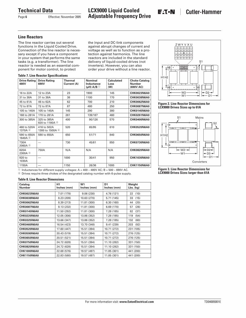
Line ReactorsThe line reactor carries out several functions in the Liquid Cooled Drive. Connection of the line reactor is neces-sary except if you have a component in your system that performs the same tasks (e.g. a transformer). The line reactor is needed as an essential com-ponent for motor control, to protect
the input and DC-link components against abrupt changes of current and voltage as well as to function as a pro-tection against harmonics. The line reactors are included in the standard delivery of liquid-cooled drives (not inverters). However, you can also order your drive without a line reactor.
Table 7. Line Reactor Specifications
� Inductances for different supply voltages: A = 400 – 480V AC; B = 500 – 690V AC.� Drives require three chokes of the designated catalog number with 6-pulse supply.
Table 8. Line Reactor Dimensions
Drive Rating480V
Drive Rating690V
ThermalCurrent (A)
NominalInductance(µH) A/B �
Calculated Loss(W)
Choke CatalogNumber(690V AC)
16 to 22A 12 to 23A 23 1900 145 CHK0023N6A0
31 to 38A 31 to 38A 38 1100 170 CHK0038N6A0
45 to 61A 46 to 62A 62 700 210 CHK0062N6A0
72 to 87A 72 to 87A 87 480 250 CHK0087N6A0
105 to 140A 105 to 140A 145 290 380 CHK0145N6A0
168 to 261A 170 to 261A 261 139/187 460 CHK0261N6A0
300 to 385A 325 to 385A820 to 1180A �
400 90/126 570 CHK0400N6A0
460 to 520A1370A �
416 to 502A 1300 to 1500A �
520 65/95 610 CHK0520N6A0
590 to 650A 1640A �
590 to 650A 650 51/71 840 CHK0650N6A0
730A 2060A �
— 730 45/61 850 CHK0730N6A0
820A 2300A �
750A N/A N/A N/A CHK0820N6A0
920 to 1030A
— 1000 30/41 950 CHK1030N6A0
1150A — 1150 26/36 1000 CHK1150N6A0
CatalogNumber
H1Inches (mm)
W1Inches (mm)
D1Inches (mm)
WeightLbs. (kg)
CHK0023N6A0 7.01 (178) 9.06 (230) 4.76 (121) 22 (10)
CHK0038N6A0 8.23 (209) 10.63 (270) 5.71 (145) 33 (15)
CHK0062N6A0 8.39 (213) 11.81 (300) 6.30 (160) 44 (20)
CHK0087N6A0 9.13 (232) 11.81 (300) 6.69 (170) 57 (26)
CHK0145N6A0 11.50 (292) 11.81 (300) 7.28 (185) 82 (37)
CHK0220N6A0 12.05 (306) 13.86 (352) 7.28 (185) 119 (54)
CHK0325N6A0 13.66 (347) 13.86 (352) 7.28 (185) 132 (60)
CHK0460N6A0 16.54 (423) 13.70 (348) 9.41 (239) 203 (92)
CHK0520N6A0 17.60 (447) 15.51 (394) 10.71 (272) 231 (105)
CHK0590N6A0 20.43 (519) 15.51 (394) 10.71 (272) 276 (125)
CHK0650N6A0 20.51 (521) 15.51 (394) 10.71 (272) 276 (125)
CHK0750N6A0 24.72 (628) 15.51 (394) 11.10 (282) 331 (150)
CHK0820N6A0 24.72 (628) 15.51 (394) 11.10 (282) 331 (150)
CHK1000N6A0 22.68 (576) 19.57 (497) 11.85 (301) 441 (200)
CHK1150N6A0 22.83 (580) 19.57 (497) 11.85 (301) 441 (200)
Figure 2. Line Reactor Dimensions for LCX9000 Drives Sizes up to 61A
Figure 3. Line Reactor Dimensions for LCX9000 Drives Sizes larger than 61A
Z W Y
H2
W2
S1
D2
V X U
H1
W1 D1
H2
Mains
Converters
H1
W2W1
D2D3
D1
S1
S2

TD04005001E For more information visit: www.EatonElectrical.com
Technical DataEffective: November 2005 Page 7
LCX9000 Liquid Cooled Adjustable Frequency Drive
Dimensions
Figure 4. Approximate Dimensions, CH3
Figure 5. Approximate Dimensions, CH4
W3 D1
Front Side
Bottom
Top
R1
W2W1
H2 R2
H3
H1
W1W2
W3 D1
FrontRight Side Left Side
H1
H2
H3
R1
R1
Bottom
Top
For more information visit: www.EatonElectrical.com TD04005001E
Technical DataPage 8 Effective: November 2005
LCX9000 Liquid Cooled Adjustable Frequency Drive
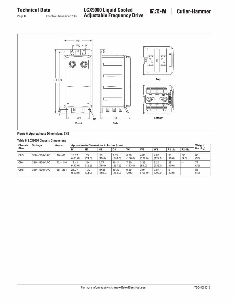
Figure 6. Approximate Dimensions, CH5
Table 9. LCX9000 Chassis Dimensions
W3 D1
W1
Front Side
H2
W2 R1
H3H1
R1 Bottom
Top
Chassis Size
Voltage Amps Approximate Dimensions in Inches (mm) Weight lbs. (kg)H1 H2 H3 D1 W1 W2 W3 R1 dia. R2 dia.
CH3 380 – 500V AC 16 – 61 16.97(431.0)
.53(13.5)
.59(15.0)
9.69(246.0)
6.30(160.0)
4.80(122.0)
4.80(122.0)
.39(10.0)
.35(9.0)
66(30)
CH4 380 – 500V AC 72 – 140 19.41(493.0)
.49(12.5)
1.77(45.0)
10.14(257.5)
7.60(193.0)
3.35(85.0)
5.24(133.0)
.39(10.0)
— 77(35)
CH5 380 – 500V AC 168 – 261 21.77(553.0)
1.30(33.0)
19.88(505.0)
10.39(264.0)
9.69(246)
3.94(100.0)
7.87(200.0)
.51(13.0)
— 88(40)
TD04005001E For more information visit: www.EatonElectrical.com
Technical DataEffective: November 2005 Page 9
LCX9000 Liquid Cooled Adjustable Frequency Drive
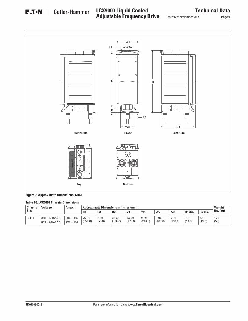
Figure 7. Approximate Dimensions, CH61
Table 10. LCX9000 Chassis Dimensions
D1W3
Left SideFrontRight Side
BottomTop
W2
W1
R2
H2
H3 H1
R1
Chassis Size
Voltage Amps Approximate Dimensions in Inches (mm) Weight lbs. (kg)H1 H2 H3 D1 W1 W2 W3 R1 dia. R2 dia.
CH61 380 – 500V AC 300 – 385 25.91(658.0)
2.09(53.0)
23.23(590.0)
14.69(373.0)
9.69(246.0)
3.94(100.0)
5.91(150.0)
.55(14.0)
.51(13.0)
121(55)525 – 690V AC 170 – 208

For more information visit: www.EatonElectrical.com TD04005001E
Technical DataPage 10 Effective: November 2005
LCX9000 Liquid Cooled Adjustable Frequency Drive
Figure 8. Approximate Dimensions, CH72
Table 11. LCX9000 Chassis Dimensions
W1 R1
H1H3
H2 R2W1 D1
Front Side
BottomTop
Chassis Size
Voltage Amps Approximate Dimensions in Inches (mm) Weight lbs. (kg)H1 H2 H3 D1 W1 R1 dia. R2 dia.
CH72 380 – 500V AC 460 – 730 42.38(1076.5)
1.57(40.0)
39.37(1000.0)
14.65(372.0)
7.87(200.0)
.55(14.0)
.51(13.0)
198(90)525 – 690V AC 261 – 502

TD04005001E For more information visit: www.EatonElectrical.com
Technical DataEffective: November 2005 Page 11
LCX9000 Liquid Cooled Adjustable Frequency Drive
Figure 9. Approximate Dimensions, CH63
Table 12. LCX9000 Chassis Dimensions
H3
H2
W2R1 D1W1
Left SideRight Side Front
BottomTop
H1
Chassis Size
Voltage Amps Approximate Dimensions in Inches (mm) Weight lbs. (kg)H1 H2 H3 D1 W1 W2 R1 dia.
CH63 380 – 500V AC 820 – 1030 36.36(923.5)
.91(23.0)
34.39(873.5)
15.35(390.0)
19.88(505.0)
13.98(355.0)
.43(11.0)
264(120)525 – 690V AC 590 – 750

For more information visit: www.EatonElectrical.com TD04005001E
Technical DataPage 12 Effective: November 2005
LCX9000 Liquid Cooled Adjustable Frequency Drive
Figure 10. Approximate Dimensions, CH74
Table 13. LCX9000 Chassis Dimensions
W3W4 W4
W2
W1
D1
Front Side
BottomTop
R1
R2
H2
H1 H3
Chassis Size
Voltage Amps Approximate Dimensions in Inches (mm) Weight lbs. (kg)H1 H2 H3 D1 W1 W2 W3 W4 R1 dia. R2 dia.
CH74 380 – 500V AC 1370 – 2300 42.38(1076.5)
1.57(40.0)
39.37(1000.0)
14.65(372.0)
29.06(738.0)
.91(23.0)
7.87(200.0)
9.69(246)
.51(13.0)
.55(14.0)
617(280)525 – 690V AC 820 – 1500

TD04005001E For more information visit: www.EatonElectrical.com
Technical DataEffective: November 2005 Page 13
LCX9000 Liquid Cooled Adjustable Frequency Drive
Control Unit Dimensions
Figure 11. Approximate Dimensions, Control Unit
Table 14. LCX9000 Control Unit Dimensions
D1
D2H2
H3H1
W1
Side
Back
Front
Bottom
Approximate Dimensions in Inches (mm) Weight Lbs. (kg)H1 H2 H3 D1 D2 W1
12.93(328.5)
.33(8.5)
11.81(300.0)
2.95(75.0)
.33(8.5)
5.75(146.0)

For more information visit: www.EatonElectrical.com TD04005001E
Technical DataPage 14 Effective: November 2005
LCX9000 Liquid Cooled Adjustable Frequency Drive
Cooling System Diagrams
Figure 12. Example of a Typical Cooling System
Figure 13. Example PI-Diagram of a Typical Cooling System and Connections
HeatExchanger
18.0°C30.0°C
26.1°C35.4°C
Cooling Water Inlet
Cooling Water Outlet
Customer Delivery
FrequencyConverters

TD04005001E For more information visit: www.EatonElectrical.com
Technical DataEffective: November 2005 Page 15
LCX9000 Liquid Cooled Adjustable Frequency Drive
I/O Board Wiring Diagrams
Figure 14. A9 Option Board Control Wiring
Figure 15. A2 Option Board Wiring
9
8
7
6
5
4
3
1+10 Vref
AI1+
GND
AI2+
Reference(voltage)
Control Voltage Output
Reference(current)AI2-
24Vout
DIN1
AO1+
DO1
Dotted lines indicate the connections for inverted signals
DIN3
DIN2
CMA
10
11
24V
GND
+ V<+48V
0 (4)/20mA
RL<500Ω
I<50mA
Basic I/O Board A9
2
GND
AO1-
1224Vout
15
14
13
DIN4
DIN6
DIN5
CMB
16
17
24V
GND
18
19
20
GND
RO1/1
RO1/2
RO1/3RL
Switching:<8 A / 24V DC<0.4 A / 125V DC<8 A / 250V AC
Continuous<2 Arms
AC / DC
Basic Relay Board A2
21
22
23
RO2/1
RO2/2
RO2/3
24
25
26

© 2005 Eaton CorporationAll Rights ReservedPrinted in USAPublication No. TD04005001E/CPGNovember 2005
Eaton Electrical Inc.1000 Cherrington ParkwayMoon Township, PA 15108-4312USAtel: 1-800-525-2000www.EatonElectrical.com