Embed Size (px)
Citation preview

The Advanced Guided Weapon Testbed (AGWT) at the AirForce Research Laboratory Munitions Directorate
Craig M. Ewing, Ph.D.
Integrated Guidance Simulation Branch, Eglin Air Force Base, Florida
This article describes the capabilities of the Kinetic Kill Vehicle Hardware-in-the-Loop
Simulator facility and the Virtual Munition Simulator facility co-located at the U.S. Air Force
Research Laboratory Munitions Directorate, Eglin Air Force Base, Florida. Together they
make up the Advanced Guided Weapon Testbed used to research advanced guidance components
using hardware-in-the-loop simulation as well as the exploitation and investigation of new
weapon concepts through the use of distributed simulation and wargaming.
Key words: Autonomous guided munitions; capabilities; communication; cooperative
attack; hardware-in-the-loop simulation; human-in-the loop; synthetic scene generation;
wargaming.
The U.S. Air Force Research LaboratoryMunitions Directorate’s (AFRL/RW)mission is to develop, integrate, andtransition science and technologies forair-launched munitions for the defeat
of ground, air, space, and cyber targets. Thesetechnologies advance warfighter capabilities throughthe development of guided munitions that operateautonomously or semi-autonomously to acquire, track,engage, and kill moving and fixed targets. Many ofthese new weapon systems are becoming highlycommunicative and rely on multi-sensor data fusion,human-in-the-loop confirmation, and increased firecontrol for cooperative attack.
AFRL/RW shares the Department of Defense(DoD) and Air Force vision that synthetic, or virtual,testing of these increasingly complex weapon systemswill play a critical role in future success on the jointbattlefield. To determine which guided weaponconcepts and technologies are the most beneficial tothe warfighter, they need to have a good understand-ing of the kind of capabilities that advancedtechnology can bring to the joint and coalitionbattlefield. The Advanced Guided Weapon Testbed(AGWT) allows for improved system effectiveness onthe battlefield by getting advanced weapons’ conceptsinto the hands of the warfighter early in the weaponslife cycle, providing an optimized solution, maximiz-ing interoperability, and reducing risk and cost byutilizing a high fidelity simulation to augment flighttests.
Made possible by the investment and direction ofthe Missile Defense Agency (MDA) since 1987, andwith the addition of Air Force funding in more recentyears; the Kinetic Kill Vehicle Hardware-in-the-LoopSimulator (KHILS) facility mission focuses on highfidelity hardware-in-the-loop (HWIL) simulation ofguided hit to kill weapons (Murrer, Thompson, andCoker 1999). KHILS serves as a testbed for develop-ment of HWIL test technologies for agencies aroundthe country, such as scene projectors, projector controlelectronics, high frequency motion simulation, andsynthetic scene generation. KHILS also performsGovernment-owned nondestructive HWIL testingfor guided munition hardware and software componentresearch, development, and test (such as infrared [IR],Ladar, ultra-violet [UV], millimeter wave [MMW],and visible seekers; navigation systems; advancedguidance algorithms; flight hardware and software;and integrated guidance systems). Use of the KHILSfor ground test reduces the number of flight testsneeded for critical program decisions, provides riskreduction for those flight tests that do take place, andprovides expanded operational envelope definition byinvestigating off-nominal scenario excursions. All ofthese roles help to lower overall flight test costs.
The Virtual Munition Simulator (VMS) facilityprovides a persistent distributed simulation connectiv-ity to enable advanced guidance, sensor, and otheradvanced munition technologies and concepts to playin distributed joint experiments in the engineering,testing, and training domains. It supports virtual and
Featured CapabilityITEA Journal 2010; 31: 23–33
Copyright ’ 2010 by the International Test and Evaluation Association
31(1) N March 2010 23

Report Documentation Page Form ApprovedOMB No. 0704-0188
Public reporting burden for the collection of information is estimated to average 1 hour per response, including the time for reviewing instructions, searching existing data sources, gathering andmaintaining the data needed, and completing and reviewing the collection of information. Send comments regarding this burden estimate or any other aspect of this collection of information,including suggestions for reducing this burden, to Washington Headquarters Services, Directorate for Information Operations and Reports, 1215 Jefferson Davis Highway, Suite 1204, ArlingtonVA 22202-4302. Respondents should be aware that notwithstanding any other provision of law, no person shall be subject to a penalty for failing to comply with a collection of information if itdoes not display a currently valid OMB control number.
1. REPORT DATE MAR 2010 2. REPORT TYPE
3. DATES COVERED 00-00-2010 to 00-00-2010
4. TITLE AND SUBTITLE The Advanced Guided Weapon Testbed (AGWT) at the Air ForceResearch Laboratory Munitions Directorate
5a. CONTRACT NUMBER
5b. GRANT NUMBER
5c. PROGRAM ELEMENT NUMBER
6. AUTHOR(S) 5d. PROJECT NUMBER
5e. TASK NUMBER
5f. WORK UNIT NUMBER
7. PERFORMING ORGANIZATION NAME(S) AND ADDRESS(ES) Air Force Research Laboratory,Munitions Directorate,IntegratedGuidance Simulation Branch,Eglin AFB,FL,32542
8. PERFORMING ORGANIZATIONREPORT NUMBER
9. SPONSORING/MONITORING AGENCY NAME(S) AND ADDRESS(ES) 10. SPONSOR/MONITOR’S ACRONYM(S)
11. SPONSOR/MONITOR’S REPORT NUMBER(S)
12. DISTRIBUTION/AVAILABILITY STATEMENT Approved for public release; distribution unlimited
13. SUPPLEMENTARY NOTES
14. ABSTRACT
15. SUBJECT TERMS
16. SECURITY CLASSIFICATION OF: 17. LIMITATION OF ABSTRACT Same as
Report (SAR)
18. NUMBEROF PAGES
11
19a. NAME OFRESPONSIBLE PERSON
a. REPORT unclassified
b. ABSTRACT unclassified
c. THIS PAGE unclassified
Standard Form 298 (Rev. 8-98) Prescribed by ANSI Std Z39-18
constructive simulation of advanced conceptual weap-ons, and components, with or without a human-in-the-loop. The VMS leverages state-of-the-art exper-tise from multiple disciplines including persistentdistributed environments, constructive/virtual simula-tions, HWIL, munitions and targets modeling,guidance, navigation, and control, real-time scenegeneration, and seekers, sensors, and signal processing.Without this early interaction, weapon systemsbrought to the field will suffer inadequacies in meetingthe warfighter needs, and modification costs to meetthese needs will be high. Having advanced weaponconcepts used in joint war-gaming and training games/events gives the warfighter a chance to explore andexploit new technologies, make suggestions for im-provements/modifications, help determine the Con-cept of Employment (CONEMP), and, overall, impactthe technology maturation decision process early in thelife cycle providing the best use of dollars to meet theirneeds. By having new weapon concepts accepted andvetted by the warfighter early in their life cycle, theweapons developed by the Air Force will continue toplay an important role in the success of the warfighteron the battlefield at a lower cost.
Both facilities together combine to comprise thestate-of-the-art 10,000 plus square foot AGWT,consisting of high throughput computational resources,physical effects simulators, environmental chambers,scene projectors, synthetic scene generation, and flightmotion simulators, which realistically exercise inte-grated guided missile concepts in a simulated flightenvironment. This testbed is helping in research,development, test, and evaluation (RDT&E) ofadvanced weapon concepts, sensors, multi-sourcesensor/data fusion, weapon targeting, and guidancealgorithms in a joint netted environment. In addition,the AGWT provides an environment for flight test riskreduction studies uncovering hardware and softwareissues that could jeopardize the success of a flight test.All evaluations can be performed as stand-aloneinternal research activities or as part of a distributedsimulation capability in either unclassified or classifiedenvironments.
AGWT resourcesConstructive/virtual/real-time simulationcomputational resources
The heart of any simulation capability begins withthe computers that run the software that is simulatingthe vehicle and its environment, and there is a greatdeal of computational capability in these facilities. TheAGWT computational equipment suite is a collectionof computer systems uniquely configured and integrat-ed to support real-time simulation, high volume data
reduction, and the hardware and digital modelinterfacing requirements of HWIL and distributedsimulation.
i-Hawks. Three modular concurrent iHawk serversystems function as the principal real-time modelingand control computers. These computers solve themissile 6 degree of freedom equations, contain modelsof missile subsystem components not present ashardware, and compute the target states and theengagement geometry. Miss distance requirements andthe small time constants for signal processing,guidance, and propulsion subsystems demand accurateand efficient computation to keep pace with high-speed hardware test articles. Commands for thephysical simulators, the flight motion simulators, andthe image generation systems are also generated here.
16 CPU Beowulf cluster. This cluster performs thetask of visualization for a large eight-screen data wall,as well as for the dual-seat F-15 cockpit simulator. TheAGWT is currently using the commercially availableFlightGear software to visualize the weapon flightenvironment. This suite of computers is also availableto drive the instrument panels and the visible imageryavailable to the pilot in the F-15 cockpit simulator.
IBM Blade center. A 64-processor IBM Blade centeris used primarily to perform Monte Carlo constructivesimulations that are used to evaluate target acquisition,recognition, and tracking algorithms. This multipro-cessor architecture is ideally suited for distributing alarge quantity of runs over many processors forevaluation against numerous closing engagements andscenarios.
Dual-core Xeon PC’s. Through KHILS’ test technol-ogy development efforts on real-time PC-based scenegeneration, some aspects of HWIL simulation can nowbe performed with standard desktop computers. Thesecomputers are spread throughout the seven worksta-tions and can be configured to run scene generationsoftware, simulate operator ground control stations, oranything that needs to be computed as part of theHWIL environment.
Flight Motion Simulators (FMS)A key aspect of performing HWIL is to accurately
simulate the motion of the weapon system duringflight. The FMS tables are used to impart flight-likeangular dynamics to the test article’s sensor, gimbals,and inertial instrumentation. The KHILS flightmotion simulators are electro-hydraulic and electro-magnetic devices designed to subject the test article tohigh dynamic range rotational motion as might beexperienced in an actual engagement. The five- and
Ewing
24 ITEA Journal
three-axis FMS are electrically commanded andhydraulically driven to achieve the high bandwidthrequired to simulate a closed loop engagement withlarge inertias and large amplitudes, whereas the highfrequency motion table simulates low amplitude, smallinertia jitter. The five-axis table is capable ofreproducing bandwidths up to 35 Hz, while thesmaller three-axis table can simulate frequencies upto 60 Hz.
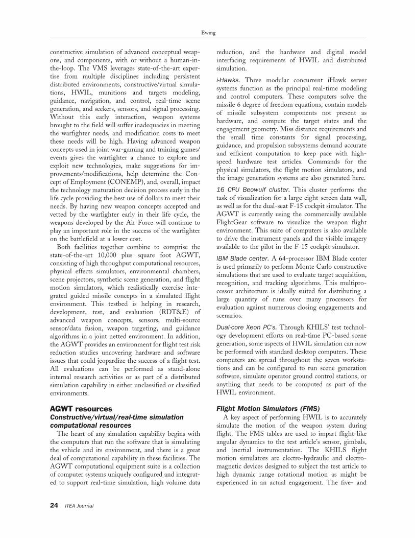
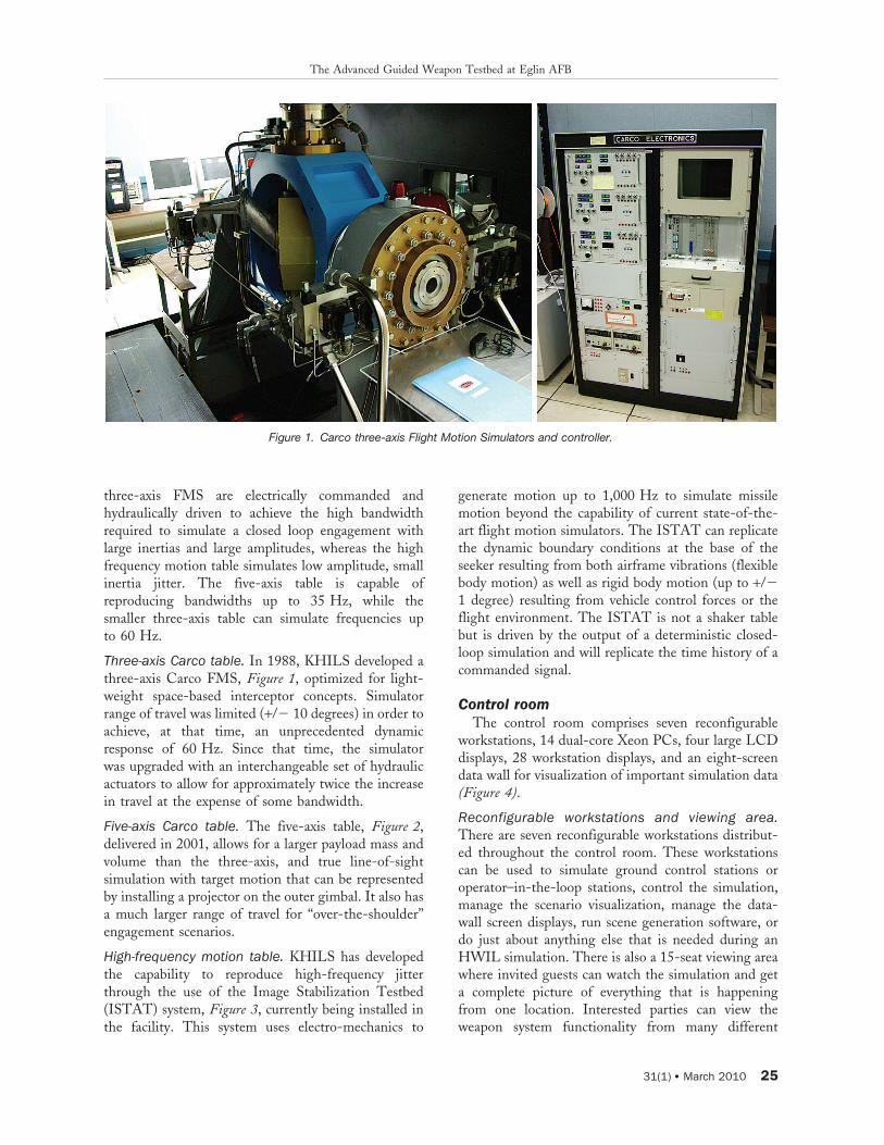
Three-axis Carco table. In 1988, KHILS developed athree-axis Carco FMS, Figure 1, optimized for light-weight space-based interceptor concepts. Simulatorrange of travel was limited (+/2 10 degrees) in order toachieve, at that time, an unprecedented dynamicresponse of 60 Hz. Since that time, the simulatorwas upgraded with an interchangeable set of hydraulicactuators to allow for approximately twice the increasein travel at the expense of some bandwidth.
Five-axis Carco table. The five-axis table, Figure 2,delivered in 2001, allows for a larger payload mass andvolume than the three-axis, and true line-of-sightsimulation with target motion that can be representedby installing a projector on the outer gimbal. It also hasa much larger range of travel for ‘‘over-the-shoulder’’engagement scenarios.
High-frequency motion table. KHILS has developedthe capability to reproduce high-frequency jitterthrough the use of the Image Stabilization Testbed(ISTAT) system, Figure 3, currently being installed inthe facility. This system uses electro-mechanics to
generate motion up to 1,000 Hz to simulate missilemotion beyond the capability of current state-of-the-art flight motion simulators. The ISTAT can replicatethe dynamic boundary conditions at the base of theseeker resulting from both airframe vibrations (flexiblebody motion) as well as rigid body motion (up to +/21 degree) resulting from vehicle control forces or theflight environment. The ISTAT is not a shaker tablebut is driven by the output of a deterministic closed-loop simulation and will replicate the time history of acommanded signal.
Control roomThe control room comprises seven reconfigurable
workstations, 14 dual-core Xeon PCs, four large LCDdisplays, 28 workstation displays, and an eight-screendata wall for visualization of important simulation data(Figure 4).
Reconfigurable workstations and viewing area.There are seven reconfigurable workstations distribut-ed throughout the control room. These workstationscan be used to simulate ground control stations oroperator–in-the-loop stations, control the simulation,manage the scenario visualization, manage the data-wall screen displays, run scene generation software, ordo just about anything else that is needed during anHWIL simulation. There is also a 15-seat viewing areawhere invited guests can watch the simulation and geta complete picture of everything that is happeningfrom one location. Interested parties can view theweapon system functionality from many different
Figure 1. Carco three-axis Flight Motion Simulators and controller.
The Advanced Guided Weapon Testbed at Eglin AFB
31(1) N March 2010 25

perspectives, and warfighters get a chance to experiencenew weapon systems and see the real hardware in live,virtual, and constructive war games and training events.
Data wall. The data/video wall, Figure 5, comprisesindividual display devices placed edge to edge toproduce a larger unified display. The wall consists ofeight, 52-inch LCD flat panel displays, a video wallprocessor, DVD-R, and a high quality sound system.The video wall can be configured to display both videoand data signals. When married with its video wallprocessor, the wall displays a Windows desktopmirroring what you’d see on a PC. Additional inputs
can be added to the video wall processor to displaysatellite and camera feeds, as well as DVD and VCRsignals. The processor allows an operator to selectnetwork applications and to size and move themseamlessly across the video wall. The video wall candisplay a broad range of sources that allow the user toaccess and utilize the information in a consistent andintuitive way. As a monitoring tool, the video wallenhances the user’s effectiveness in responding toproblems as they arise. By looking at the expansive datawall and surrounding monitors, the operator can watchcritical parameters of the simulation; see the projectedimagery, the sensed imagery, and the autopilotfunctions; monitor the flight motion table; view thesynthetic imagery; and access a host of other functions.
Human-in-the-loop capabilityAn F-15 dual seat cockpit simulator, Figure 6, serves
to offer a human-in-the-loop capability to the testingenvironment. This cockpit can be used to allow a pilotto gain experience with the targeting and missionplanning associated with new weapon concepts.Although originally an F-15 cockpit simulator, thecockpit display can be driven to show displays for boththe front or rear seat and new functionality can beadded to any screen. Important information can begained by using feedback on workload and problemsassociated with launching multiple weapon systemsfrom future platforms.
Figure 3. Five-axis high frequency Flight Motion
Simulator table.
Figure 2. Carco five-axis Flight Motion Simulators and controller.
Ewing
26 ITEA Journal

Figure 4. Control room with reconfigurable workstations (top left & right) and viewing area (bottom).
Figure 5. Data wall display.
The Advanced Guided Weapon Testbed at Eglin AFB
31(1) N March 2010 27

Scene projectionThe AGWT performs HWIL testing on imaging
sensors having autonomous discrimination, track, andaimpoint algorithms, requiring a robust projectioncapability. There are numerous types of scene projec-tors that have been developed for use in KHILS as wellas by many other HWIL facilities (Williams, Gold-smith, and Stockbridge 2005). This gives us thecapability to project synthetic imagery to the unitsunder test in the specific waveband they expect to seeduring an actual flight. We currently have projectors inthe infrared (IR), visible, and Ladar wavebands.
Infrared scene projection. Infrared scene projectioncapability has grown rapidly in KHILS to include theWideband Infrared Scene Projector (WISP), theMulti-Spectral Scene Projector (MSSP), and theOptimized Array for Space-background InfraredSimulation (OASIS). Figure 7 shows a 512 3 512IR MSSP projector along with its associated collimatoroptics that collimates the light and focuses the image atinfinity.
Figure 8 shows a 512 3 512 programmable highdynamic range resistive array IR OASIS projector. TheOASIS array is optimized to operate in cryogenicchamber environments; however, it will also functionvery well at room temperature. High fidelity syntheticIR imagery is projected through this device to a seekerunit under test. The generation of this imagery isdescribed in the Synthetic Scene Generation section.
Imagery from two or more devices can be combinedthrough a diachronic beam combiner to presentmultiple waveband imagery to a seeker under test(Sieglinger 2006). Each resistor in the array, or pixel, isindividually controlled by regulating the current flowthrough the resistor, thus regulating the resistor’sradiance output. This allows KHILS to test the fullfunctionality of the seeker including optics, focal planearray, and processor.
Ladar scene projection. Several organizations in theDoD are developing Ladar seekers, and it is necessaryto be able to stimulate these articles in a HWIL testenvironment. An ongoing effort to develop a large-format Ladar scene projector has been underway forseveral years. KHILS has already demonstrated thecapability to digitally inject synthetic Ladar imagery toa sensor under test. Research programs are nowunderway to develop a 256 3 256 Ladar sceneprojector capable of providing imagery to the nextgeneration of Ladar seekers. An eight-channel Ladarscene projector has been used for previous weaponseeker testing. Because of its large size, if we were toexpand this to 65,000+ channels we would need a newbuilding to hold all the racks of equipment. Numerousresearch projects into laser diodes, arbitrary waveformgenerators, photonic modulators, high-speed D to Aconverters, and many other areas will allow us todevelop the next generation Ladar scene projector in afraction of the space.
Figure 6. F-15 dual-seat cockpit simulator.
Figure 7. Multi-Spectral Scene Projector infrared projector (left), collimator optics (right).
Ewing
28 ITEA Journal

Visible scene projection. New weapon system seekersare being developed with much wider fields of viewthan previous seekers. The AGWT has recognized theneed to stimulate those sensors during HWIL testing,and in 2009, a Wide-Field-Of-View (WFOV) visiblemulti-projector system, Figure 9, is being installed inthe AGWT. The WFOV projector system is a 4-meterdome, which uses 10 projectors to produce an imagethat is 220 degrees in azimuth and 135 degrees inelevation. Research into an IR WFOV projectorsystem is beginning as well.
Projector array control electronics. Through KHILS’technology development efforts in array controlelectronics, talented engineers have designed the PC-based Array Control Electronics or PACE (Goldsmithet al. 2003). PACE is an inexpensive, robust, andreconfigurable set of electronics that can supportlegacy, current, and upcoming emitter array projectors.The PACE electronics systems are manufactured and
tested in the KHILS facility and have been successfullytransitioned to numerous MDA, Air Force, U.S.Army, and U.S. Navy test facilities.
Infrared projector characterizationKHILS has established a nationwide reputation as
an expert in non-uniformity correction (NUC) ofresistive array IR scene projectors. These types ofprojectors suffer from an inherent non-uniformityamong the individual elements. The uncorrectedelements may exhibit 10 to 20 percent spatial variationwhen commanded with the same drive voltage.Methods have been developed over the past decadefor NUC of resistor array projectors. After correction,the element response variation can be reduced to theorder of a percent or two, depending mainly on theNUC camera errors (Flynn et al. 2003; Joyce,Swierkowski, and Williams 2006; Meshell et al.2008; Sisko et al. 2006).
Figure 8. Optimized Array for Space-background Infrared Simulation 512 3 512 infra-red scene projector (IRSP) (left), raw imagerycaptured with infrared camera (right).
Figure 9. Visible wide-field-of-view projector system.
The Advanced Guided Weapon Testbed at Eglin AFB
31(1) N March 2010 29

Synthetic scene generationTo provide inputs to all of these different types of
scene projectors, we have an extensive real-timesynthetic scene generation capability. The AGWT’sprimary function relates to high fidelity endgamesimulations of visible, IR, MMW, and Ladar seekers,and the closing guidance sequences require thatKHILS engineers merge aerodynamics, 6 degree offreedom analysis, aerodynamic heating, and signaturepredictions in a real-time sequence. The code used togenerate these images in the AGWT is called theReal-Time Composite High Altitude Missile Plume(RTC) code.
RTC began as a code called Composite HighAltitude Missile Plume (CHAMP) (Crow and Coker1998), developed by KHILS in the late 1980s as a toolto render complex targets, such as missiles with fins,multi-warhead post-boost vehicles, and waking reentryvehicles. CHAMP incorporates the time-dependentsignature phenomena, based on computed hard-bodythermal response owing to radiation and convectionheat loads. It also models external source effects,including solar reflection, earth shine, and plumeimpingement. Over the years, the CHAMP code hasbeen updated to include modeling of tactical airbreathing targets such as aircraft, cruise missiles,maritime, and ground-based targets. It has also beenmade to run real-time for use as RTC for performingHWIL simulations. Figure 10 shows examples of RTCoutput for ballistic missiles and air breathing threats.Figure 11 shows some examples of maritime andground-based target imagery generated with theRTC code.
As urban combat has become an important part ofthe warfighter’s mission, the AGWT is developing a
capability to exercise advanced weapons with realisticsynthetic urban imagery in real time. The capability togenerate urban scenes as high fidelity, spectrally correctimages has been completed under a Small BusinessInnovative Research (SBIR) program with TerraSimusing their product TerraTools (Figure 12). Work iscurrently ongoing to merge the urban scene generationwith RTC to provide a real-time capability for use inthe HWIL environment.
Environmental chambersSome weapon systems are designed to operate in
unique operational backgrounds, or require specialenvironments for repeatable high fidelity groundtesting. KHILS has several unique capabilities toprovide the appropriate operational environment forHWIL testing.
Cryogenic chamber. The first is the KHILS VacuumCold Chamber (KVACC). The KVACC consists of acooled optical collimator and source chamber inside avacuum chamber in a class 1000 clean room and hasestablished the capability to perform IR scene projec-tion for HWIL testing with significantly reduced IRbackgrounds. The cold background of this systemreduces the overall thermal noise floor, therebyincreasing the available dynamic range of the projec-tion system. The all-reflective optics in KVACCprovides the capability of simultaneous mid-wave andlong-wave IR scene projection. A sensor chamber hasbeen added to the main KVACC chamber, providingfor testing of seeker hardware and/or vacuum-capableIR cameras. Also, a gaseous helium refrigerationsystem has been installed, greatly reducing the logisticsand operational overhead of dealing with LN2. The
Figure 10. Air breathing and ballistic missile real-time CHAMP outputs in various wavebands.
Ewing
30 ITEA Journal

new refrigeration system provides a chill-downcapability to about 50 to 60 K (Thompson et al.2006).
Radio Frequency (RF) environmental chamber. TheAGWT also includes a 21 3 26 3 16 foot tall X-bandanechoic chamber located in a 100-dB shielded roomto accommodate ground testing of RF systems. Thereis a moveable flight table mount that allows a flighttable to be inserted into the middle of the room forarticulation of test articles inside the chamber. There is
an antenna array wall at the other end with access tothe RF chamber.
Global Positioning System (GPS) simulatorAs GPS is an important function for many weapon
systems, the AGWT has the capability to simulate afully operational GPS environment using the InterstateElectronics Global Positioning System. The GPSsimulator can provide up to 24 channels of L1/L2satellite information to a missile system.
Figure 12. Urban scene generation examples in various wavebands.
Figure 11. Ground and maritime real-time CHAMP output in various wavebands.
The Advanced Guided Weapon Testbed at Eglin AFB
31(1) N March 2010 31

Distributed connectivityThe AGWT is capable of connecting to the outside
world through many different networks including theDefense Research and Engineering Network (DREN),the secret form of the DREN known as the SDREN,MDA-Net, and the Joint Mission Environment TestCapability (JMETC) virtual private network. TheAGWT can operate in both classified and unclassifiedmodes. This connectivity has been used with severalwar games and joint experiments including the JointExpeditionary Forces Experiments (JEFX) and theAdvanced Concept Exploration (ACE) experiments.
SummaryKHILS has long been recognized as a national test
resource for the development of HWIL test technologyand the nondestructive HWIL performance testing ofprecision guided missile systems and subsystems. Withthe recent addition of the Virtual Munition Simulator,the AGWT is the Air Force Research Lab’s one-stopshop for researching and demonstrating advancedweapon system components and systems throughHWIL and distributed simulation. AGWT testengineers provide pretest planning, integration, testexecution, data observations and collection, andposttest data analysis on a variety of guidancesubsystem technologies.
While the AGWT prides itself in being a leader in thedesign of scene projectors and electronics, synthetic scenegeneration, distributed simulation, and PC-based real-time hardware, the facility offers much more. It is morethan a facility filled with computers, hardware, software,and electronics. The AGWT resources also consist ofdedicated people with the vision and determination tocontinually push the state-of-the-art technologies forHWIL and distributed testing. Numerous scientists andengineers from the Munitions Directorate and itscontractor support base have dedicated their lives tomaking the AGWT a national asset. C
CRAIG M. EWING graduated from The Ohio State
University, Columbus, Ohio, in 1986 with a bachelor of
science degree in aeronautical/astronautical engineering.
He accepted a job with the United States Air Force civil
service at Eglin Air Force Base, Florida, where he worked
on guidance, navigation, and control issues for the
Strategic Defense Initiative for 7 years, specializing in
the area of guidance and estimation. While working at
Eglin, he enrolled at the University of Florida Graduate
Engineering Research Center to pursue a master’s degree.
He received a master of science degree in aerospace
engineering in 1992 and a doctor of philosophy degree in
engineering mechanics in 1999, both from the Universityof Florida. In 1994, he was assigned to the Air ForceResearch Laboratory (AFRL) Munitions Directorate teamworking to analyze advanced concepts at engagement andmission levels. He then accepted a position as the technicaladvisor for the Integrated Guidance Simulation Branchspecializing in HWIL and synthetic scene generation foradvanced munitions. He is currently the technical advisorfor the Planning & Assessment Division at the AFRLMunitions Directorate, whose responsibilities includestrategic planning and simulation-based acquisition usinglethality & vulnerability assessment, computational me-chanics analysis, and engagement and mission levelanalysis for the Air Force. E-mail: [email protected]
ReferencesCrow, D. R., and C. F. Coker. 1998. Composite
hardbody and missile plume (CHAMP98) IR targetscene generation program. In Technologies for SyntheticEnvironments: Hardware-in-the-Loop Testing III. Pro-ceedings SPIE 3368, April 13–15 1998, Orlando,Florida, pp. 256–268. Bellingham, WA: SPIE.
Flynn, David S., R. Bryan Sisko, Breck A.Sieglinger, and Rhoe A. Thompson. 2003. Radiomet-rically calibrating spectrally coupled 2-color projectors.In Conference on Technologies for Synthetic Environ-ments: Hardware-in-the-Loop Testing VIII. SPIE 5092-15, April 21–22 2003, Orlando, Florida, pp. 155–164.Bellingham, WA: SPIE.
Goldsmith II, George C., W. Larry Herald, RickyA. Erickson, Walter S. Irvine Jr., Paul R. Mackin, PaulBryant, and Brian Lindberg. 2003. Setting the PACEin IRSP: A reconfigurable PC-based array controlelectronics system for infrared scene projection. InSPIE Defense and Security Symposium, Orlando, Flor-ida, April 2–22 2003, pp. 61–70. Bellingham, WA:SPIE.
Meshell, William M., Breck A. Sieglinger, StevenA. Marlow, August J. Huber, David R. Forester, andMichael K. Deiler. 2008. Nonuniformity correction forlarge format resistor arrays. In SPIE Defense andSecurity Symposium, Orlando, Florida. Bellingham,WA: SPIE.
Murrer, Robert Lee Jr., Rhoe A. Thompson, andCharles F. Coker. 1999. Developments at the Kinetic-Kill Vehicle Hardware-in-the-Loop Simulator(KHILS) Facility. In SPIE Defense and SecuritySymposium, Orlando, Florida, April 5–7, 1999, pp.31–48. Bellingham, WA: SPIE.
Sieglinger, Breck A., Steven A. Marlow, Richard B.Sisko, and Rhoe A. Thompson. 2006. Procedures andrecent results for 2-color infrared projection. In SPIEDefense and Security Symposium, Orlando, Florida,
Ewing
32 ITEA Journal

April 18 2006, pp. 62080z-1-9. Bellingham, WA:SPIE.
Sisko, R. Bryan, Rhoe A. Thompson, Steven A.Marlow, and Breck A. Sieglinger. 2006. Resistor arraywaveband nonuniformity measurements and RNUC bandconverter, SPIE Defense and Security Symposium, April 182006, pp. 62080y-1-10. Bellingham, WA: SPIE.
Thompson, R. A., W. L. Herald, T. P. Bergin, S. A.Marlow, and E. W. Glattke. 2006. Advances in cryo-vacuum test capabilities for dual-band sensors at the
kinetic kill vehicle hardware-in-the-loop simulation(KHILS) facility. In SPIE Defense and SecuritySymposium, April 13–14 2006, Orlando, Florida, pp.107–117. Bellingham, WA: SPIE.
Williams, Owen M., George C. Goldsmith II, andRobert G. Stockbridge. 2005. History of resistor arrayinfrared projectors: Hindsight is always 100% opera-bility. In SPIE Defense and Security Symposium, March29 2005, Orlando, Florida, pp. 212–228. Bellingham,WA: SPIE.
The Advanced Guided Weapon Testbed at Eglin AFB
31(1) N March 2010 33