Embed Size (px)
Citation preview
Configuring User Authentication
This chapter provides the following information about configuring and monitoring user authentication on Enterasys® N‐Series, S‐Series®, and K‐Series modular switches, A‐Series, B‐Series, C‐Series stackable fixed switches, and D‐Series, G‐Series, and I‐Series standalone fixed switches.
What is User Authentication?Authentication is the ability of a network access server, with a database of valid users and devices, to acquire and verify the appropriate credentials of a user or device (supplicant) attempting to gain access to the network. Enterasys authentication uses the RADIUS protocol to control access to switch ports from an authentication server and to manage the message exchange between the authenticating device and the server. Both MultiAuth and Multi‐user authentication are supported. MultiAuth is the ability to configure multiple authentication modes for a user and apply the authentication mode with the highest precedence. Multi‐user is the ability to appropriately authenticate multiple supplicants on a single link and provision network resources, based upon an appropriate policy for each supplicant. The Enterasys switch products support the following five authentication methods:
• IEEE 802.1x
• MAC‐based Authentication (MAC)
• Port Web Authentication (PWA)
Note: Through out this document:
• Use of the term “modular switch” indicates that the information is valid for the N-Series, S-Series, and K-Series platforms.
• Use of the term “stackable fixed switch” indicates that the information is valid for the A-Series, B-Series, and C-Series platforms.
• Use of the term “standalone fixed switch” indicates that the information is valid for the D-Series, G-Series, and I-Series platforms.
For information about... Refer to page...
What is User Authentication? 1
Why Would I Use It in My Network? 2
How Can I Implement User Authentication? 2
Authentication Overview 2
Configuring Authentication 14
Authentication Configuration Example 29
Terms and Definitions 34
April 15, 2011 Page 1 of 36
Why Would I Use It in My Network?
• Convergence End Point (CEP)
• RADIUS Snooping
Enterasys switch products support the configuration of up to three simultaneous authentication methods per user, with a single authentication method applied based upon MultiAuth authentication precedence.
Why Would I Use It in My Network?Network resources represent a major capital investment for your organization and can be vulnerable to both undesired resource usage and malicious intent from outside users. Authentication provides you with a user validation function which assures that the supplicant requesting access has the right to do so and is a known entity. To the degree a supplicant is not a known entity, access can be denied or granted on a limited basis. The ability of authentication to both validate a user’s identity and define the resources available to the user assures that valuable network resources are being used for the purposes intended by the network administrator.
How Can I Implement User Authentication?Take the following steps to implement user authentication:
• Determine the types of devices to be authenticated.
• Determine the correct authentication type for each device.
• Determine an appropriate policy best suited for the use of that device on your network.
• Configure RADIUS user accounts on the authentication server for each device.
• Configure user authentication.
Authentication Overview
Note: The RADIUS Snooping user authentication feature is detailed in the Configuring RADIUS Snooping feature guide. The RADIUS Snooping feature guide can be found at: https://extranet.enterasys.com/downloads.
Note: See the Enterasys Matrix X Core Router Configuration Guide for X-Series switch authentication configuration information.
For information about... Refer to page...
IEEE 802.1x Using EAP 3
MAC-Based Authentication (MAC) 3
Port Web Authentication (PWA) 3
Convergence End Point (CEP) 4
Multi-User And MultiAuth Authentication 4
Remote Authentication Dial-In Service (RADIUS) 8
April 15, 2011 Page 2 of 36
Authentication Overview
IEEE 802.1x Using EAPThe IEEE 802.1x port‐based access control standard allows you to authenticate and authorize user access to the network at the port level. Access to the switch ports is centrally controlled from an authentication server using RADIUS. The Extensible Authentication Protocol (EAP), defined in RFC 3748, provides the means for communicating the authentication information.
There are three supported types of EAP:
• MD5 – EAP‐MD5 is a challenge‐handshake protocol over EAP that authenticates the user with a normal username and password.
• TLS – EAP‐TLS provides a transport layer security based upon the presentation and acceptance of digital certificates between the supplicant and the authentication server.
• Protected – Protected Extensible Authentication Protocol (PEAP) optionally authenticates the authentication server to the client using an X‐509 certificate using a TLS tunnel, after which the client authentication credentials are exchanged.
All Enterasys platforms support IEEE 802.1x, which protects against unauthorized access to a network, DoS attacks, theft of services and defacement of corporate web pages.
802.1x configuration consists of setting port, global 802.1x parameters, and RADIUS parameters on the switches to point the switch to the authentication server. The Filter‐ID RADIUS attribute can be configured on the authentication server to direct dynamic policy assignment on the switch to the 802.1x authenticating end system.
MAC-Based Authentication (MAC)MAC‐based authentication (MAC) authenticates a device using the source MAC address of received packets. The authenticator sends the authentication server a source MAC address as the user name and a password that you configure on the switch. If the authentication server receives valid credentials from the switch, RADIUS returns an Accept message to the switch. MAC authentication enables switches to authenticate end systems, such as printers and camcorder devices that do not support 802.1x or web authentication. Since MAC‐based authentication authenticates the device, not the user, and is subject to MAC address spoofing attacks, it should not be considered a secure authentication method. However, it does provide a level of authentication for a device where otherwise none would be possible.
The modular switch, stackable fixed switch, and standalone fixed switch devices support MAC‐based authentication.
Port Web Authentication (PWA)Port Web Authentication (PWA) authenticates a user by utilizing a web browser for the login process to authenticate to the network. To log in using PWA, a user opens the web browser requesting a URL that either directly accesses the PWA login page or is automatically redirected to the login page. At the PWA login page, the user enters a login username and password. On the switch, either the Challenge Handshake Authentication Protocol (CHAP) or the Password Authentication Protocol (PAP) verifies the username and password credentials provided to the authentication server. If the credentials are validated, the authentication server returns a RADIUS Accept message, optionally containing Filter‐ID or tunnel attributes, to the switch.
PAP uses an unencrypted password. CHAP uses the password to generate a digest that is transmitted to the authentication server. If RADIUS determines that the digest matches the digest generated on the authentication server, access is granted. The acceptance message back to the
April 15, 2011 Page 3 of 36
Authentication Overview
switch can contain any Filter‐ID attribute configured on the authentication server, allowing policy to be applied for the authenticating user.
PWA enhanced mode is supported. PWA enhanced mode allows a user on an un‐authenticated PWA port to enter any URL into the browser and be presented the PWA login page on their initial web access. When enhanced mode is disabled, a user must enter the correct URL to access login.
The modular switches, B‐Series and C‐Series stackable fixed switches, and the standalone fixed switches support PWA.
Convergence End Point (CEP)CEP detects an IP telephony or video device on a port and dynamically applies a specific policy to the port. The switch detects a convergence end point by inspecting received packets for specific traffic attributes. CEP does not require a RADIUS configuration.
The CEP implementation supports the following detection methods:
• Cisco Phone Detection ‐ the firmware parses a Cisco Discovery Protocol (CDP) packet to identify the phone type. If it was sent by an IP phone, the firmware uses the phone type. A response is sent back to the phone, verifying authentication.
• Siemens HiPath Phone Detection ‐ TCP/UPD port number snooping is used. Port 4060 is the default port for communication.
• H.323 Phone Detection ‐ TCP/UDP port number snooping and reserved IP address snooping are used. Ports 1718 ‐ 1720 and IP address 224.0.1.41 are the default values.
• Session Initiation Protocol (SIP) Phone Detection ‐ TCP/UDP port number snooping and reserved IP address snooping are used. Port 5060 and IP address 224.0.1.75 are the default values.
The modular switches support CEP.
Multi-User And MultiAuth AuthenticationThis section will discuss multi‐user and MultiAuth authentication. Multi‐user and MultiAuth are separate concepts. The primary difference between the two is as follows:
• Multi‐user authentication refers to the ability to authenticate multiple users and devices on the same port, with each user or device being provided the appropriate level of network resources based upon policy.
• MultiAuth authentication refers to the ability of a single or multiple user(s), device(s), or port(s) to successfully authenticate using multiple authentication methods at the same time, such as 802.1x, PWA, and MAC, with precedence determining which authentication method is actually applied to that user, device, or port.
Note: For stackable fixed switches and standalone fixed switches:
• One user per PWA-configured port can be authenticated
• PWA authentication supports RFC 3580 VLAN authorization on B3, B5, C3, C5,and G3 devices
April 15, 2011 Page 4 of 36
Authentication Overview
Multi-User AuthenticationMulti‐user authentication provides for the per‐user or per‐device provisioning of network resources when authenticating. It supports the ability to receive from the authentication server:
• A policy traffic profile, based on the user account’s RADIUS Filter‐ID configuration
• A base VLAN‐ID, based on the RFC 3580 tunnel attributes configuration, also known as dynamic VLAN assignment
When a single supplicant connected to an access layer port authenticates, a policy profile can be dynamically applied to all traffic on the port. When multi‐user authentication is not implemented, and more than one supplicant is connected to a port, firmware does not provision network resources on a per‐user or per‐device basis. Different users or devices may require a different set of network resources. The firmware tracks the source MAC address for each authenticating user regardless of the authenticating protocol being used. Provisioning network resources on a per‐user basis is accomplished by applying the policy configured in the RADIUS Filter‐ID, or the base VLAN‐ID configured in the RFC 3580 tunnel attributes, for a given user’s MAC address. The RADIUS Filter‐ID and tunnel attributes are part of the RADIUS user account and are included in the RADIUS Accept message response from the authentication server.
The number of allowed users per port can be configured using the set multiauth port numusers command. The show multiauth port command displays both the allowed number of users configured and the maximum number of users supported per port for the device. The allowed number of users defaults to the maximum number of supported users for the port for a modular switch platform and to 1 for the stackable fixed switch and standalone fixed switch platforms.
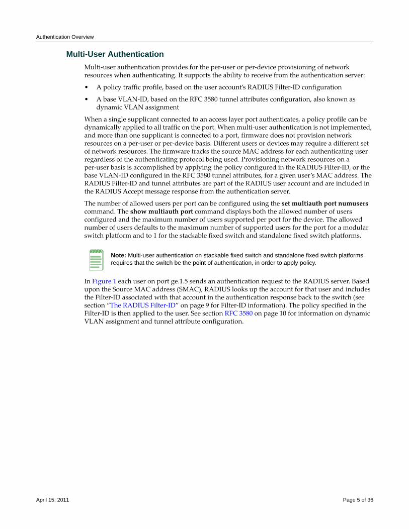
In Figure 1 each user on port ge.1.5 sends an authentication request to the RADIUS server. Based upon the Source MAC address (SMAC), RADIUS looks up the account for that user and includes the Filter‐ID associated with that account in the authentication response back to the switch (see section “The RADIUS Filter‐ID” on page 9 for Filter‐ID information). The policy specified in the Filter‐ID is then applied to the user. See section RFC 3580 on page 10 for information on dynamic VLAN assignment and tunnel attribute configuration.
Note: Multi-user authentication on stackable fixed switch and standalone fixed switch platforms requires that the switch be the point of authentication, in order to apply policy.
April 15, 2011 Page 5 of 36
Authentication Overview
Figure 1 Applying Policy to Multiple Users on a Single Port
MultiAuth AuthenticationAuthentication mode support provides for the global setting of a single authentication mode 802.1X (strict‐mode) or multiple modes (MultiAuth) per user or port when authenticating.
Strict mode is the appropriate mode when authenticating a single 802.1X user. All traffic on the port receives the same policy in strict mode. When authenticating PWA, CEP, or MAC, you must use MultiAuth authentication, whether authenticating a single or multiple supplicants.
MultiAuth authentication supports the simultaneous configuration of up to three authentication methods per user on the same port, but only one method per user is actually applied. When MultiAuth authentication ports have a combination of authentication methods enabled, and a user is successfully authenticated for more than one method at the same time, the configured authentication method precedence will determine which RADIUS‐returned Filter‐ID will be processed and result in an applied traffic policy profile. See “Setting MultiAuth Authentication Precedence” on page 21 for authentication method precedence details.
The number of users or devices MultiAuth authentication supports depends upon the type of device, whether the ports are fixed access or uplink, and whether increased port capacity or extra chassis user capacity MUA licenses have been applied. See the firmware customer release note that comes with your device for details on the number of users or devices supported per port.
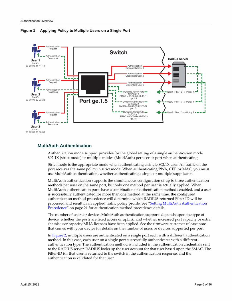
In Figure 2, multiple users are authenticated on a single port each with a different authentication method. In this case, each user on a single port successfully authenticates with a different authentication type. The authentication method is included in the authentication credentials sent to the RADIUS server. RADIUS looks up the user account for that user based upon the SMAC. The Filter‐ID for that user is returned to the switch in the authentication response, and the authentication is validated for that user.
User 1SMAC
00-00-00-11-11-11
User 2SMAC
00-00-00-22-22-22
User 3SMAC
00-00-00-33-33-33
AuthenticationRequest
AuthenticationCredentials User 2
User1 Filter ID --> Policy X
User2 Filter ID --> Policy Y
User3 Filter ID --> Policy Z
AuthenticationCredentials User 1
AuthenticationCredentials User 3
Dynamic Admin Rulefor Policy 1
SMAC = 00-00-00-11-11-11ge.1.5
Dynamic Admin Rulefor Policy 2
SMAC = 00-00-00-22-22-22ge.1.5
Dynamic Admin Rulefor Policy 3
SMAC = 00-00-00-33-33-33ge.1.5
AuthenticationResponse
AuthenticationRequest
AuthenticationResponse
AuthenticationRequest
Switch
AuthenticationResponse
Radius Server
Port ge.1.5
April 15, 2011 Page 6 of 36
Authentication Overview
Figure 2 Authenticating Multiple Users With Different Methods on a Single Port
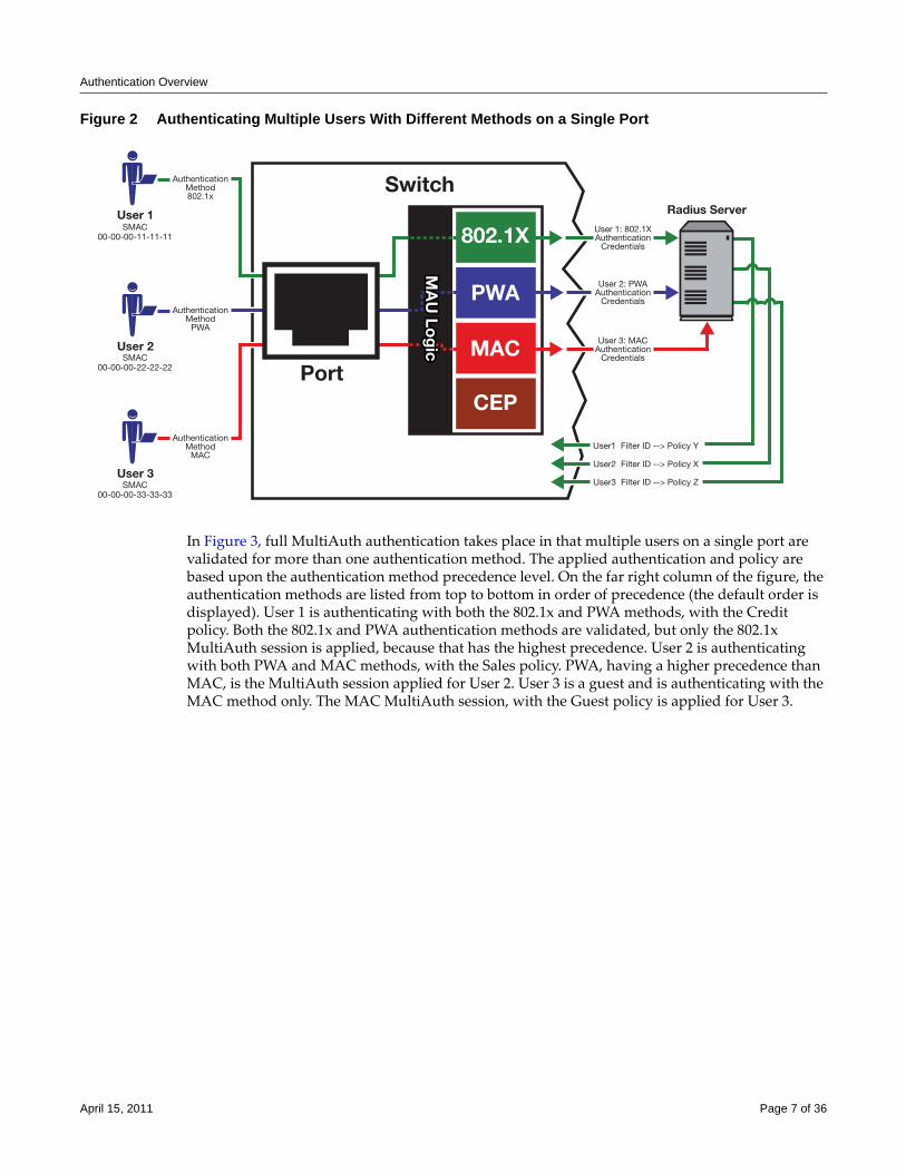
In Figure 3, full MultiAuth authentication takes place in that multiple users on a single port are validated for more than one authentication method. The applied authentication and policy are based upon the authentication method precedence level. On the far right column of the figure, the authentication methods are listed from top to bottom in order of precedence (the default order is displayed). User 1 is authenticating with both the 802.1x and PWA methods, with the Credit policy. Both the 802.1x and PWA authentication methods are validated, but only the 802.1x MultiAuth session is applied, because that has the highest precedence. User 2 is authenticating with both PWA and MAC methods, with the Sales policy. PWA, having a higher precedence than MAC, is the MultiAuth session applied for User 2. User 3 is a guest and is authenticating with the MAC method only. The MAC MultiAuth session, with the Guest policy is applied for User 3.
User 1SMAC
00-00-00-11-11-11
User 2SMAC
00-00-00-22-22-22
User 3SMAC
00-00-00-33-33-33
AuthenticationMethod802.1x
User1 Filter ID --> Policy Y
User2 Filter ID --> Policy X
User3 Filter ID --> Policy Z
User 1: 802.1XAuthentication
Credentials
User 2: PWAAuthentication
Credentials
User 3: MACAuthentication
Credentials
AuthenticationMethod
MAC
AuthenticationMethod
PWA
SwitchRadius Server
Port
802.1X
PWA
MAC
CEP
MA
U Lo
gic
MA
U Lo
gic
April 15, 2011 Page 7 of 36
Authentication Overview
Figure 3 Selecting Authentication Method When Multiple Methods are Validated
Remote Authentication Dial-In Service (RADIUS)This section provides details for the configuration of RADIUS and RFC 3580 attributes.
The Remote Authentication Dial‐In User Service (RADIUS) is an extensible protocol used to carry authentication and authorization information between the switch and the Authentication Server (AS). RADIUS is used by the switch for communicating supplicant supplied credentials to the authentication server and the authentication response from the authentication server back to the switch. This information exchange occurs over the link‐layer protocol.
The switch acts as a client to RADIUS using UDP port 1812 by default (configurable in the set radius command). The authentication server contains a database of valid supplicant user accounts with their corresponding credentials. The authentication server checks that the information received from the switch is correct, using authentication schemes such as PAP, CHAP, or EAP. The authentication server returns an Accept or Reject message to the switch based on the credential validation performed by RADIUS. The implementation provides enhanced network security by using a shared secret and MD5 password encryption.
SMAC=User 1 SMAC=User 2 SMAC=User 3
SwitchMultiAuth Sessions Auth. Agent
CreditPolicy Role
SalesPolicy Role
GuestPolicy Role
Port X
802.1X
PWA
MAC
CEPM
AU
Log
ic
<User 1, 802.1x, Authenticated, PID=Credit, Applied>
<User 2, PWA, Authenticated, PID=Sales, Applied>
<User 1, PWA, Authenticated, PID=Credit, Not Applied>
<User 3, MAC, Authenticated, PID=Guest, Applied>
<User 1, MAC, Authenticated, PID=Guest, Not Applied>
<User 2, MAC, Authenticated, PID=Guest, Not Applied>
For information about... Refer to page...
How RADIUS Data Is Used 9
The RADIUS Filter-ID 9
RFC 3580 10
Policy Maptable Response 12
April 15, 2011 Page 8 of 36
Authentication Overview
Required authentication credentials depend upon the authentication method being used. For 802.1x and PWA authentication, the switch sends username and password credentials to the authentication server. For MAC authentication, the switch sends the device MAC address and a password configured on the switch to the authentication server. The authentication server verifies the credentials and returns an Accept or Reject message back to the switch.
How RADIUS Data Is UsedThe Enterasys switch bases its decision to open the port and apply a policy or close the port based on the RADIUS message, the portʹs default policy, and unauthenticated behavior configuration.
RADIUS provides accounting functionality by way of accounting packets from the switch to the RADIUS server, for such session statistics as start and end, total packets, and session end reason events. This data can be used for both billing and network monitoring purposes.
Additionally RADIUS is widely used by VoIP service providers. It is used to pass login credentials of a SIP end point (like a broadband phone) to a SIP Registrar using digest authentication, and then to the authentication server using RADIUS. Sometimes it is also used to collect call detail records (CDRs) later used, for instance, to bill customers for international long distance.
If you configure an authentication method that requires communication with an authentication server, you can use the RADIUS Filter‐ID attribute to dynamically assign either a policy profile or management level to authenticating supplicants.
The RADIUS Filter-IDThe RADIUS Filter‐ID attribute consists of a string that is formatted in the RADIUS Access‐Accept packet sent back from the authentication server to the switch during the authentication process.
Each user can be configured in the RADIUS server database with a RADIUS Filter‐ID attribute that specifies the name of either a policy profile or management level the user should be assigned upon successful authentication. During the authentication process, when the authentication server returns a RADIUS Access‐Accept packet that includes a Filter‐ID matching a policy profile name configured on the switch, the switch then dynamically applies the policy profile to the physical port the supplicant is authenticating on.
The decorated Filter‐ID supports a policy attribute, a management access attribute, or both in the following formats:
Enterasys:version=1:policy=policyname
Enterasys:version=1:mgmt=access-mgmtType
Enterasys:version=1:mgmt=access-mgmtType:policy=policyname
policyname is the name of the policy to apply to this authentication.
access‐mgmtTypes supported are: ro (read‐only), rw (read‐write), and su (super‐user).
The un‐decorated Filter‐ID supports the policy attribute only in the following format:
policyname
The undecorated format is simply a string that specifies a policy profile name. The undecorated format cannot be used for management access authentication. Decorated Filter‐IDs are processed first. If no decorated Filter‐IDs are found, then undecorated Filter‐IDs are processed. If multiple Filter‐IDs are found that contain conflicting values, a Syslog message is generated.
April 15, 2011 Page 9 of 36
Authentication Overview
RFC 3580Enterasys switches support the RFC 3580 RADIUS tunnel attribute for dynamic VLAN assignment. The VLAN‐Tunnel‐Attribute implements the provisioning of service in response to a successful authentication. On ports that do not support policy, the packet will be tagged with the VLAN‐ID. The VLAN‐Tunnel‐Attribute defines the base VLAN‐ID to be applied to the user.
Dynamic VLAN AssignmentThe RADIUS server may optionally include RADIUS tunnel attributes in a RADIUS Access‐Accept message for dynamic VLAN assignment of the authenticated end system.
RFC 3580’s RADIUS tunnel attributes are often configured on a RADIUS server to dynamically assign users belonging to the same organizational group within an enterprise to the same VLAN, or to place all offending users according to the organization’s security policy in a Quarantine VLAN. Tunnel attributes are deployed for enterprises that have end system authentication configured on the network. For example, all engineers can be dynamically assigned to the same VLAN upon authentication, while sales are assigned to another VLAN upon authentication.
The name of the feature on Enterasys platforms that implements dynamic VLAN assignment through the receipt of RADIUS tunnel attributes is VLAN authorization. VLAN authorization depends upon receipt of the RFC 3580 RADIUS tunnel attributes in RADIUS Access‐Accept messages. VLAN authorization must be enabled globally and on a per‐port basis for the Tunnel attributes to be processed. When disabled per port or globally, the device will not process Tunnel attributes.
The firmware supports VLAN authorization on the modular swithches, stackable fixed switches, and standalone fixed switches.
By default, all policy‐capable Enterasys platforms will dynamically assign a policy profile to the port of an authenticating user based on the receipt of the Filter‐ID RADIUS attribute. This is not the case for RADIUS tunnel attributes in that, by default, VLAN authorization is disabled.
The N‐Series, starting in firmware release 5.31.xx, the S‐Series, and K‐Series platforms support RFC 3580 RADIUS VLAN Tunnel attributes .
VLAN Authorization AttributesThree Tunnel attributes are used for dynamic VLAN Authorization:
• Tunnel‐Type attribute (Type=64, Length=6, Tag=0, Value=0x0D for VLAN)
• Tunnel‐Medium‐Type attribute (Type=65, Length=6, Tag=0, Value=0x06 for 802 media)
• Tunnel‐Private‐Group‐ID attribute (Type=81, Length>=3, String=VID in ASCII)
The Tunnel‐Type attribute indicates the tunneling protocol to be used when this attribute is formatted in RADIUS Access‐Request messages, or the tunnel protocol in use when this attribute is formatted in RADIUS Access‐Accept messages. Set Tunnel‐Type attribute parameters as follows:
• Type: Set to 64 for Tunnel‐Type RADIUS attribute
• Length: Set to 6 for six‐byte length of this RADIUS attribute
• Tag: Provides a means of grouping attributes in the same packet which refer to the same tunnel. Valid values for this field are from 0x01 through 0x1F, inclusive. Set to 0 if unused. Unless alternative tunnel types are provided, it is only necessary for tunnel attributes to specify a single tunnel. As a result, where it is only desired to specify the VLAN‐ID, the tag field should be set to zero (0x00) in all tunnel attributes.
April 15, 2011 Page 10 of 36
Authentication Overview
• Value: Indicates the type of tunnel. A value of 0x0D (decimal 13) indicates that the tunneling protocol is a VLAN.
Tunnel‐Medium‐Type indicates the transport medium to use when creating a tunnel for the tunneling protocol, determined from Tunnel‐Type attribute. Set Tunnel‐Medium‐Type attribute parameters as follows:
• Type: Set to 65 for Tunnel‐Medium‐Type RADIUS attribute
• Length: Set to 6 for six‐byte length of this RADIUS attribute
• Tag: Provides a means of grouping attributes in the same packet which refer to the same tunnel. Valid value for this field are 0x01 through 0x1F, inclusive. Set to 0 if unused. Unless alternative tunnel types are provided, it is only necessary for tunnel attributes to specify a single tunnel. As a result, where it is only desired to specify the VLANID, the tag field should be set to zero (0x00) in all tunnel attributes.
• Value: Indicates the type of tunnel. A value of 0x06 indicates that the tunneling medium pertains to 802 media (including Ethernet)
Tunnel‐Private‐Group‐ID attribute indicates the group ID for a particular tunneled session. Set the Tunnel‐Private‐Group‐ID attribute parameters as follows:
• Type: Set to 81 for Tunnel‐Private‐Group‐ID RADIUS attribute
• Length: Set to a value greater than or equal to 3.
• Tag: Provides a means of grouping attributes in the same packet which refer to the same tunnel. Valid values for this field are from 0x01 through 0x1F, inclusive. Set to 0 if unused. Unless alternative tunnel types are provided, it is only necessary for tunnel attributes to specify a single tunnel. As a result, where it is only desired to specify the VLANID, the tag field should be set to zero (0x00) in all tunnel attributes.
• String: Indicates the group. For the VLAN ID integer value, it is encoded as a string using ASCII. For example, the VLAN ID integer value 103 would be represented as 0x313033
VLAN Authorization ConsiderationsVLAN Authorization poses some operational and management issues on the network.
• A VLAN is not a security container. It is a broadcast container and used to segment broadcast traffic on the network. ACLs implemented at the layer 3 routed interface for a VLAN only provide access control for traffic into and out of the VLAN. No access control mechanism for intra‐VLAN communications exists, therefore users within the VLAN are not protected from each other. Malicious traffic allowed onto a VLAN can potentially infect all traffic on the VLAN. Such an infection can consume valuable hardware resources on the infrastructure, such as CPU cycles and memory. Infections can be transmitted to other hosts within the VLAN and to the layer 3 routed boundary. This leads to the direct competition of malicious traffic with business critical traffic on the network.
• End‐To‐End QoS cannot be truly guaranteed if QoS is implemented at the layer 3 routed interface for a network where business critical applications are classified and prioritized.
• If VLANs are implemented to group together users that are members of the same organizational group, then a VLAN must be configured everywhere in the network topology where a member of that organizational unit may connect to the network. For example, if an engineer may connect to the network from any location, then the Engineering VLAN must be configured on all access layer devices in the network. These VLAN configurations lead to over‐extended broadcast domains as well as added configuration complexity in the network topology.
April 15, 2011 Page 11 of 36
Authentication Overview
• A problem with moving an end system to a new VLAN is that the end system must be issued an IP address on the new VLAN’s subnet to which it has become a member. If the end system does not yet have an IP address, this is not usually a problem. However, if the end system has an IP address, the lease of the address must time out before it attempts to obtain a new address, which may take some time. The IP address assignment process, implemented by DHCP, and the authentication process are not conjoined on the end system. Therefore, this leads to end systems possessing an invalid IP address after dynamic VLAN Authorization and lost IP connectivity until its current IP address times out. Furthermore, when a new IP address is eventually assigned to the end system, IP connectivity is disrupted for all applications on the end system.
Policy Maptable ResponseThe policy maptable response, or conflict resolution, feature allows you to define how the system should handle allowing an authenticated user onto a port based on the contents of the RADIUS Accept message reply. There are three possible response settings: tunnel mode, policy mode, or both tunnel and policy, also known as hybrid authentication mode.
When the maptable response is set to tunnel mode, the system will use the tunnel attributes in the RADIUS reply to apply a VLAN to the authenticating user and will ignore any Filter‐ID attributes in the RADIUS reply. When tunnel mode is configured, VLAN‐to‐policy mapping can occur if configured on a modular switch platform. VLAN‐to‐policy mapping will not occur in tunnel mode on a stackable fixed switch or standalone fixed switch platform.
When the maptable response is set to policy mode, the system will use the Filter‐ID attributes in the RADIUS reply to apply a policy to the authenticating user and will ignore any tunnel attributes in the RADIUS reply. When policy mode is configured, no VLAN‐to‐policy mapping will occur.
When the maptable response is set to both, or hybrid authentication mode, both Filter‐ID attributes (dynamic policy assignment) and tunnel attributes (dynamic VLAN assignment) sent in RADIUS Accept message replies are used to determine how the switch should handle authenticating users. When hybrid authentication mode is configured, VLAN‐to‐policy mapping can occur, as described below in When Policy Maptable Response is “Both”.
Using hybrid authentication mode eliminates the dependency on having to assign VLANs through policy roles — VLANs can be assigned by means of the tunnel attributes while policy roles can be assigned by means of the Filter‐ID attributes. Alternatively, on modular switch platforms, VLAN‐to‐policy mapping can be used to map policies to users using the VLAN specified by the tunnel attributes, without having to configure Filter‐ID attributes on the RADIUS server. This separation gives administrators more flexibility in segmenting their networks beyond the platform’s policy role limits.
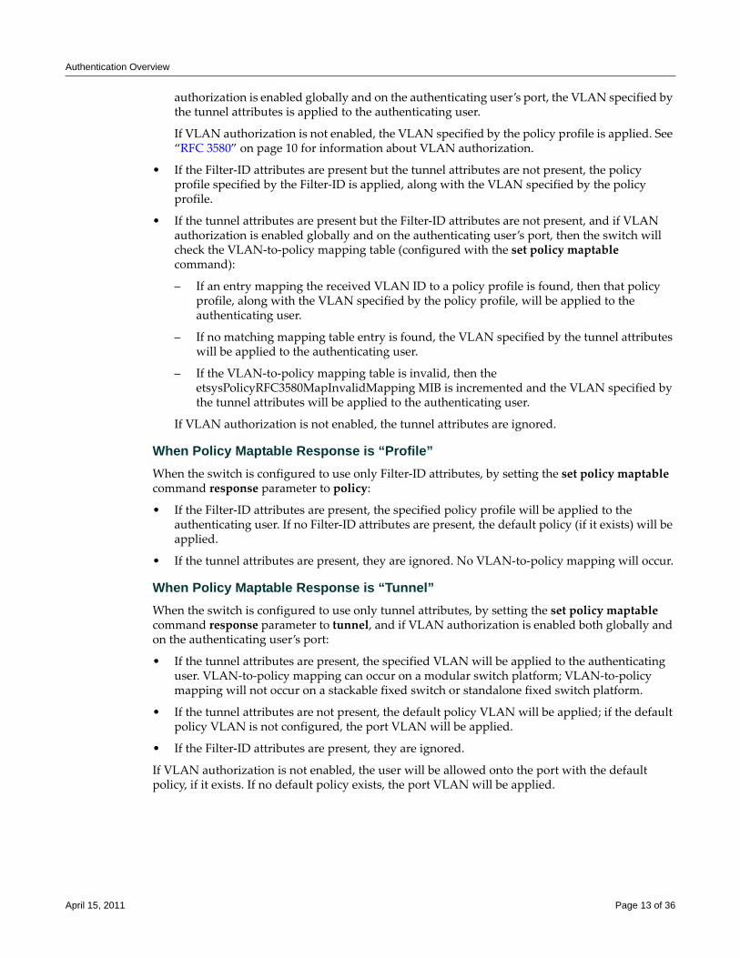
When Policy Maptable Response is “Both”Hybrid authentication mode uses both Filter‐ID attributes and tunnel attributes. To enable hybrid authentication mode, use the set policy maptable command and set the response parameter to both. When configured to use both sets of attributes:
• If both the Filter‐ID and tunnel attributes are present in the RADIUS reply, then the policy profile specified by the Filter‐ID is applied to the authenticating user, and if VLAN
Note: Hybrid authentication is supported by modular switch devices, B-Series and C-Series stackable fixed switches and the G3 device for Releases 6.3 and greater.
April 15, 2011 Page 12 of 36
Authentication Overview
authorization is enabled globally and on the authenticating user’s port, the VLAN specified by the tunnel attributes is applied to the authenticating user.
If VLAN authorization is not enabled, the VLAN specified by the policy profile is applied. See “RFC 3580” on page 10 for information about VLAN authorization.
• If the Filter‐ID attributes are present but the tunnel attributes are not present, the policy profile specified by the Filter‐ID is applied, along with the VLAN specified by the policy profile.
• If the tunnel attributes are present but the Filter‐ID attributes are not present, and if VLAN authorization is enabled globally and on the authenticating user’s port, then the switch will check the VLAN‐to‐policy mapping table (configured with the set policy maptable command):
– If an entry mapping the received VLAN ID to a policy profile is found, then that policy profile, along with the VLAN specified by the policy profile, will be applied to the authenticating user.
– If no matching mapping table entry is found, the VLAN specified by the tunnel attributes will be applied to the authenticating user.
– If the VLAN‐to‐policy mapping table is invalid, then the etsysPolicyRFC3580MapInvalidMapping MIB is incremented and the VLAN specified by the tunnel attributes will be applied to the authenticating user.
If VLAN authorization is not enabled, the tunnel attributes are ignored.
When Policy Maptable Response is “Profile”When the switch is configured to use only Filter‐ID attributes, by setting the set policy maptable command response parameter to policy:
• If the Filter‐ID attributes are present, the specified policy profile will be applied to the authenticating user. If no Filter‐ID attributes are present, the default policy (if it exists) will be applied.
• If the tunnel attributes are present, they are ignored. No VLAN‐to‐policy mapping will occur.
When Policy Maptable Response is “Tunnel” When the switch is configured to use only tunnel attributes, by setting the set policy maptable command response parameter to tunnel, and if VLAN authorization is enabled both globally and on the authenticating user’s port:
• If the tunnel attributes are present, the specified VLAN will be applied to the authenticating user. VLAN‐to‐policy mapping can occur on a modular switch platform; VLAN‐to‐policy mapping will not occur on a stackable fixed switch or standalone fixed switch platform.
• If the tunnel attributes are not present, the default policy VLAN will be applied; if the default policy VLAN is not configured, the port VLAN will be applied.
• If the Filter‐ID attributes are present, they are ignored.
If VLAN authorization is not enabled, the user will be allowed onto the port with the default policy, if it exists. If no default policy exists, the port VLAN will be applied.
April 15, 2011 Page 13 of 36
Configuring Authentication
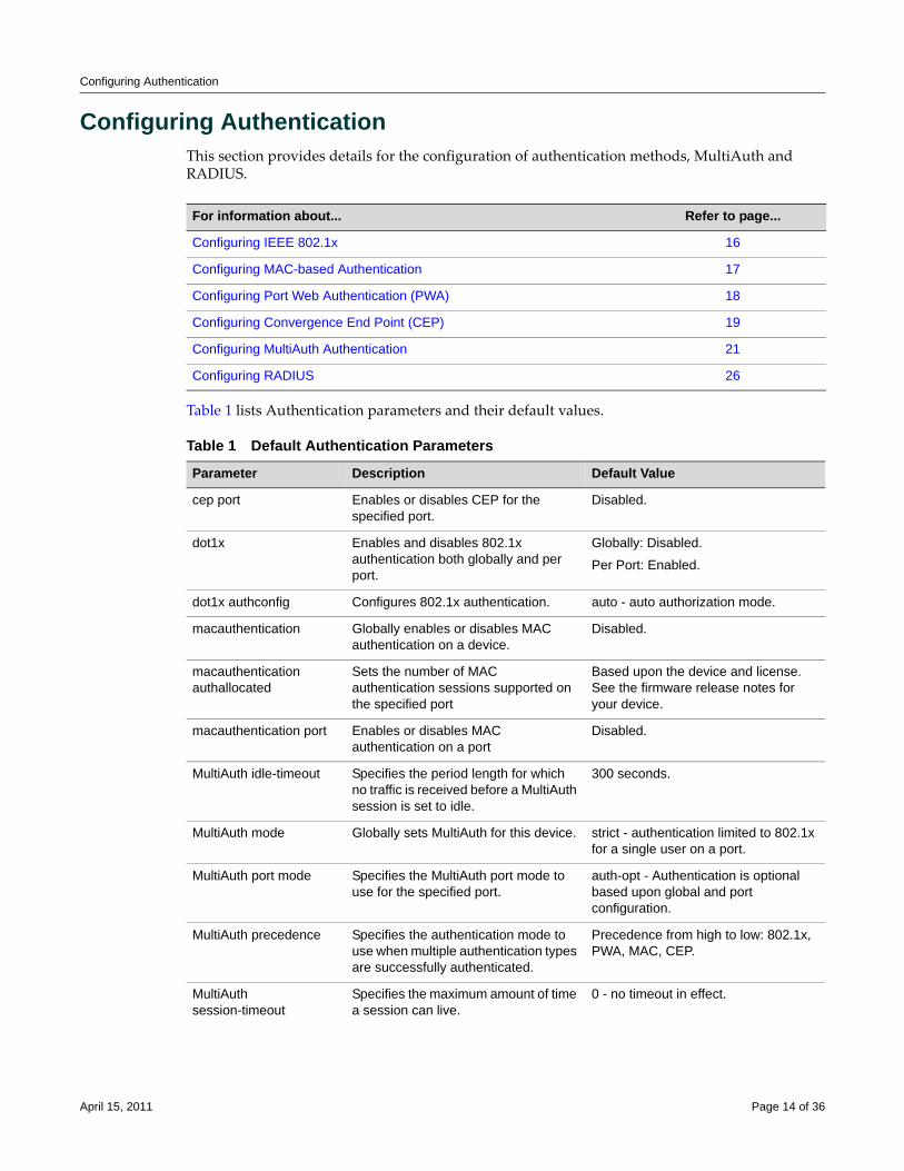
Configuring AuthenticationThis section provides details for the configuration of authentication methods, MultiAuth and RADIUS.
Table 1 lists Authentication parameters and their default values.
For information about... Refer to page...
Configuring IEEE 802.1x 16
Configuring MAC-based Authentication 17
Configuring Port Web Authentication (PWA) 18
Configuring Convergence End Point (CEP) 19
Configuring MultiAuth Authentication 21
Configuring RADIUS 26
Table 1 Default Authentication Parameters
Parameter Description Default Value
cep port Enables or disables CEP for the specified port.
Disabled.
dot1x Enables and disables 802.1x authentication both globally and per port.
Globally: Disabled.
Per Port: Enabled.
dot1x authconfig Configures 802.1x authentication. auto - auto authorization mode.
macauthentication Globally enables or disables MAC authentication on a device.
Disabled.
macauthentication authallocated
Sets the number of MAC authentication sessions supported on the specified port
Based upon the device and license. See the firmware release notes for your device.
macauthentication port Enables or disables MAC authentication on a port
Disabled.
MultiAuth idle-timeout Specifies the period length for which no traffic is received before a MultiAuth session is set to idle.
300 seconds.
MultiAuth mode Globally sets MultiAuth for this device. strict - authentication limited to 802.1x for a single user on a port.
MultiAuth port mode Specifies the MultiAuth port mode to use for the specified port.
auth-opt - Authentication is optional based upon global and port configuration.
MultiAuth precedence Specifies the authentication mode to use when multiple authentication types are successfully authenticated.
Precedence from high to low: 802.1x, PWA, MAC, CEP.
MultiAuth session-timeout
Specifies the maximum amount of time a session can live.
0 - no timeout in effect.
April 15, 2011 Page 14 of 36
Configuring Authentication
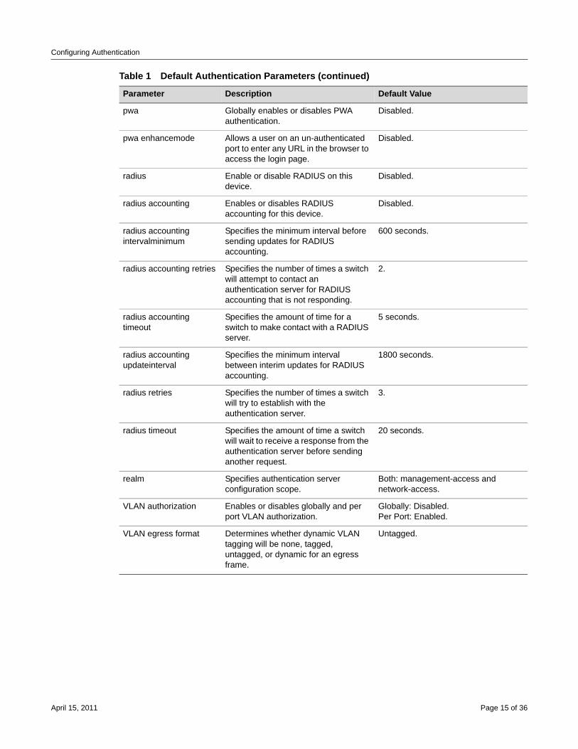
pwa Globally enables or disables PWA authentication.
Disabled.
pwa enhancemode Allows a user on an un-authenticated port to enter any URL in the browser to access the login page.
Disabled.
radius Enable or disable RADIUS on this device.
Disabled.
radius accounting Enables or disables RADIUS accounting for this device.
Disabled.
radius accounting intervalminimum
Specifies the minimum interval before sending updates for RADIUS accounting.
600 seconds.
radius accounting retries Specifies the number of times a switch will attempt to contact an authentication server for RADIUS accounting that is not responding.
2.
radius accounting timeout
Specifies the amount of time for a switch to make contact with a RADIUS server.
5 seconds.
radius accounting updateinterval
Specifies the minimum interval between interim updates for RADIUS accounting.
1800 seconds.
radius retries Specifies the number of times a switch will try to establish with the authentication server.
3.
radius timeout Specifies the amount of time a switch will wait to receive a response from the authentication server before sending another request.
20 seconds.
realm Specifies authentication server configuration scope.
Both: management-access and network-access.
VLAN authorization Enables or disables globally and per port VLAN authorization.
Globally: Disabled.Per Port: Enabled.
VLAN egress format Determines whether dynamic VLAN tagging will be none, tagged, untagged, or dynamic for an egress frame.
Untagged.
Table 1 Default Authentication Parameters (continued)
Parameter Description Default Value
April 15, 2011 Page 15 of 36
Configuring Authentication
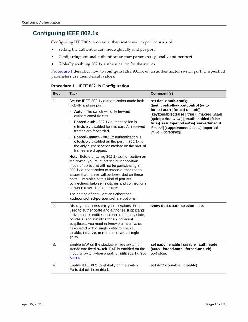
Configuring IEEE 802.1xConfiguring IEEE 802.1x on an authenticator switch port consists of:
• Setting the authentication mode globally and per port
• Configuring optional authentication port parameters globally and per port
• Globally enabling 802.1x authentication for the switch
Procedure 1 describes how to configure IEEE 802.1x on an authenticator switch port. Unspecified parameters use their default values.
Procedure 1 IEEE 802.1x Configuration
Step Task Command(s)
1. Set the IEEE 802.1x authentication mode both globally and per port:
• Auto - The switch will only forward authenticated frames.
• Forced-auth - 802.1x authentication is effectively disabled for this port. All received frames are forwarded.
• Forced-unauth - 802.1x authentication is effectively disabled on the port. If 802.1x is the only authentication method on the port, all frames are dropped.
Note: Before enabling 802.1x authentication on the switch, you must set the authentication mode of ports that will not be participating in 802.1x authentication to forced-authorized to assure that frames will be forwarded on these ports. Examples of this kind of port are connections between switches and connections between a switch and a router.
The setting of dot1x options other than authcontrolled-portcontrol are optional.
set dot1x auth-config {[authcontrolled-portcontrol {auto | forced-auth | forced-unauth}] [keytxenabled{false | true}] [maxreq value] [quietperiod value] [reauthenabled {false | true}] [reauthperiod value] [servertimeout timeout] [supptimeout timeout] [txperiod value]} [port-string]
2. Display the access entity index values. Ports used to authenticate and authorize supplicants utilize access entities that maintain entity state, counters, and statistics for an individual supplicant. You need to know the index value associated with a single entity to enable, disable, initialize, or reauthenticate a single entity.
show dot1x auth-session-stats
3. Enable EAP on the stackable fixed switch or standalone fixed switch. EAP is enabled on the modular switch when enabling IEEE 802.1x. See Step 4.
set eapol [enable | disable] [auth-mode {auto | forced-auth | forced-unauth} port-string
4. Enable IEEE 802.1x globally on the switch. Ports default to enabled.
set dot1x {enable | disable}
April 15, 2011 Page 16 of 36
Configuring Authentication
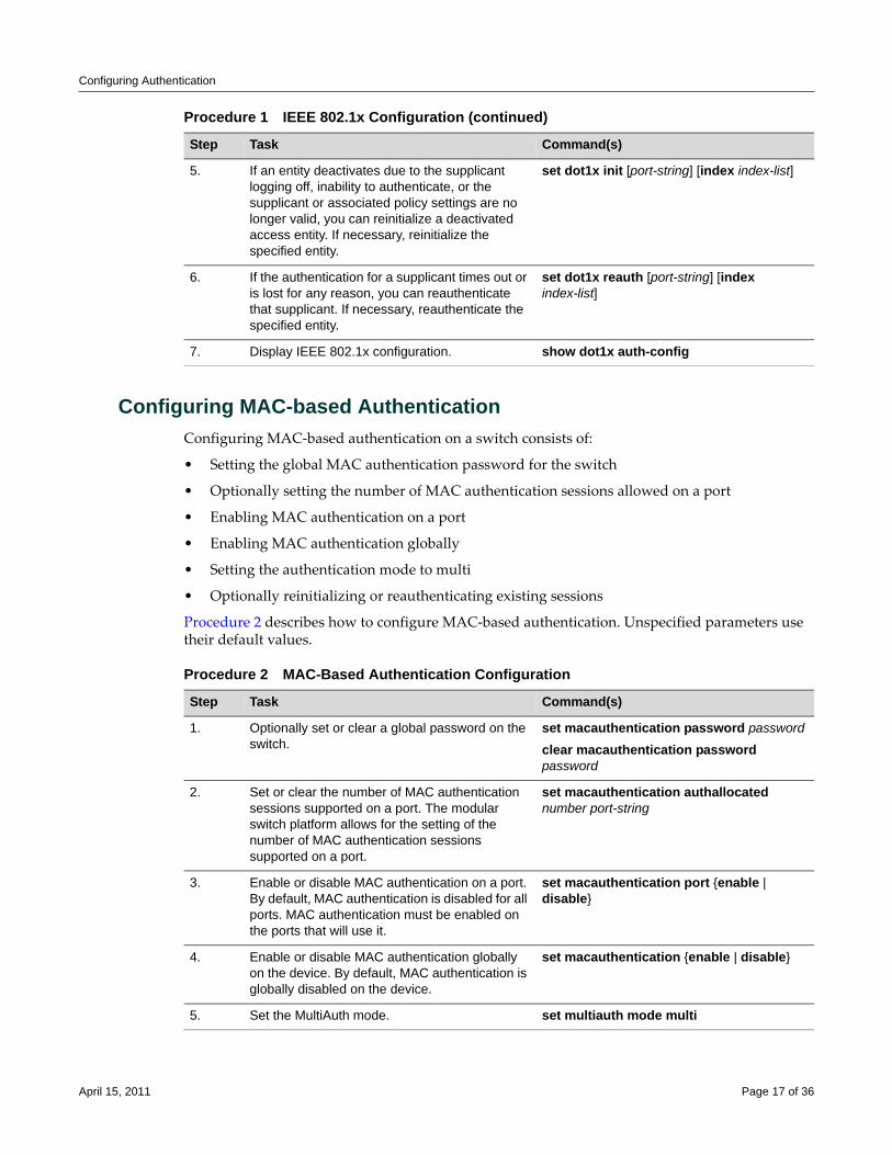
Configuring MAC-based AuthenticationConfiguring MAC‐based authentication on a switch consists of:
• Setting the global MAC authentication password for the switch
• Optionally setting the number of MAC authentication sessions allowed on a port
• Enabling MAC authentication on a port
• Enabling MAC authentication globally
• Setting the authentication mode to multi
• Optionally reinitializing or reauthenticating existing sessions
Procedure 2 describes how to configure MAC‐based authentication. Unspecified parameters use their default values.
5. If an entity deactivates due to the supplicant logging off, inability to authenticate, or the supplicant or associated policy settings are no longer valid, you can reinitialize a deactivated access entity. If necessary, reinitialize the specified entity.
set dot1x init [port-string] [index index-list]
6. If the authentication for a supplicant times out or is lost for any reason, you can reauthenticate that supplicant. If necessary, reauthenticate the specified entity.
set dot1x reauth [port-string] [index index-list]
7. Display IEEE 802.1x configuration. show dot1x auth-config
Procedure 1 IEEE 802.1x Configuration (continued)
Step Task Command(s)
Procedure 2 MAC-Based Authentication Configuration
Step Task Command(s)
1. Optionally set or clear a global password on the switch.
set macauthentication password password
clear macauthentication password password
2. Set or clear the number of MAC authentication sessions supported on a port. The modular switch platform allows for the setting of the number of MAC authentication sessions supported on a port.
set macauthentication authallocated number port-string
3. Enable or disable MAC authentication on a port. By default, MAC authentication is disabled for all ports. MAC authentication must be enabled on the ports that will use it.
set macauthentication port {enable | disable}
4. Enable or disable MAC authentication globally on the device. By default, MAC authentication is globally disabled on the device.
set macauthentication {enable | disable}
5. Set the MultiAuth mode. set multiauth mode multi
April 15, 2011 Page 17 of 36
Configuring Authentication
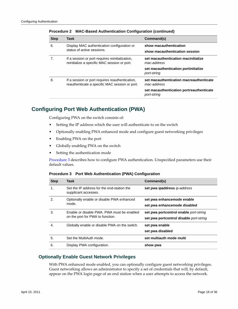
Configuring Port Web Authentication (PWA)Configuring PWA on the switch consists of:
• Setting the IP address which the user will authenticate to on the switch
• Optionally enabling PWA enhanced mode and configure guest networking privileges
• Enabling PWA on the port
• Globally enabling PWA on the switch
• Setting the authentication mode
Procedure 3 describes how to configure PWA authentication. Unspecified parameters use their default values.
Optionally Enable Guest Network PrivilegesWith PWA enhanced mode enabled, you can optionally configure guest networking privileges. Guest networking allows an administrator to specify a set of credentials that will, by default, appear on the PWA login page of an end station when a user attempts to access the network.
6. Display MAC authentication configuration or status of active sessions.
show macauthenticationshow macauthentication session
7. If a session or port requires reinitialization, reinitialize a specific MAC session or port.
set macauthentication macinitialize mac-address
set macauthentication portinitialize port-string
8. If a session or port requires reauthentication, reauthenticate a specific MAC session or port.
set macauthentication macreauthenticate mac-address
set macauthentication portreauthenticate port-string
Procedure 2 MAC-Based Authentication Configuration (continued)
Step Task Command(s)
Procedure 3 Port Web Authentication (PWA) Configuration
Step Task Command(s)
1. Set the IP address for the end-station the supplicant accesses.
set pwa ipaddress ip-address
2. Optionally enable or disable PWA enhanced mode.
set pwa enhancemode enableset pwa enhancemode disabled
3. Enable or disable PWA. PWA must be enabled on the port for PWA to function.
set pwa portcontrol enable port-string
set pwa portcontrol disable port-string
4. Globally enable or disable PWA on the switch. set pwa enableset pwa disabled
5. Set the MultiAuth mode. set multiauth mode multi
6. Display PWA configuration. show pwa
April 15, 2011 Page 18 of 36
Configuring Authentication
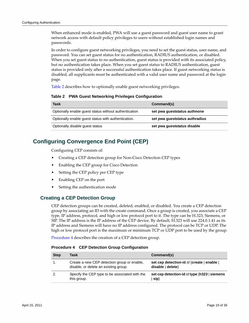
When enhanced mode is enabled, PWA will use a guest password and guest user name to grant network access with default policy privileges to users without established login names and passwords.
In order to configure guest networking privileges, you need to set the guest status, user name, and password. You can set guest status for no authentication, RADIUS authentication, or disabled. When you set guest status to no authentication, guest status is provided with its associated policy, but no authentication takes place. When you set guest status to RADIUS authentication, guest status is provided only after a successful authentication takes place. If guest networking status is disabled, all supplicants must be authenticated with a valid user name and password at the login page.
Table 2 describes how to optionally enable guest networking privileges.
Configuring Convergence End Point (CEP)Configuring CEP consists of:
• Creating a CEP detection group for Non‐Cisco Detection CEP types
• Enabling the CEP group for Cisco Detection
• Setting the CEP policy per CEP type
• Enabling CEP on the port
• Setting the authentication mode
Creating a CEP Detection GroupCEP detection groups can be created, deleted, enabled, or disabled. You create a CEP detection group by associating an ID with the create command. Once a group is created, you associate a CEP type, IP address, protocol, and high or low protocol port to it. The type can be H.323, Siemens, or SIP. The IP address is the IP address of the CEP device. By default, H.323 will use 224.0.1.41 as its IP address and Siemens will have no IP address configured. The protocol can be TCP or UDP. The high or low protocol port is the maximum or minimum TCP or UDP port to be used by the group.
Procedure 4 describes the creation of a CEP detection group.
Table 2 PWA Guest Networking Privileges Configuration
Task Command(s)
Optionally enable guest status without authentication set pwa gueststatus authnone
Optionally enable guest status with authentication. set pwa gueststatus authradius
Optionally disable guest status set pwa gueststatus disable
Procedure 4 CEP Detection Group Configuration
Step Task Command(s)
1. Create a new CEP detection group or enable, disable, or delete an existing group.
set cep detection-id id {create | enable | disable | delete}
2. Specify the CEP type to be associated with the this group.
set cep detection-id id type {h323 | siemens | sip}
April 15, 2011 Page 19 of 36
Configuring Authentication
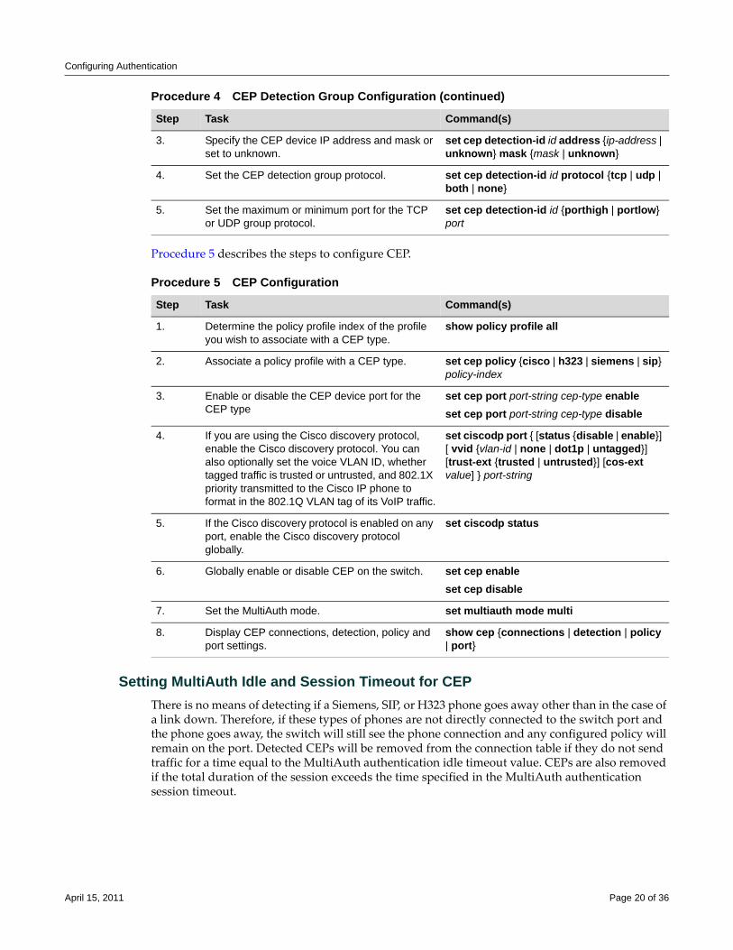
Procedure 5 describes the steps to configure CEP.
Setting MultiAuth Idle and Session Timeout for CEPThere is no means of detecting if a Siemens, SIP, or H323 phone goes away other than in the case of a link down. Therefore, if these types of phones are not directly connected to the switch port and the phone goes away, the switch will still see the phone connection and any configured policy will remain on the port. Detected CEPs will be removed from the connection table if they do not send traffic for a time equal to the MultiAuth authentication idle timeout value. CEPs are also removed if the total duration of the session exceeds the time specified in the MultiAuth authentication session timeout.
3. Specify the CEP device IP address and mask or set to unknown.
set cep detection-id id address {ip-address | unknown} mask {mask | unknown}
4. Set the CEP detection group protocol. set cep detection-id id protocol {tcp | udp | both | none}
5. Set the maximum or minimum port for the TCP or UDP group protocol.
set cep detection-id id {porthigh | portlow} port
Procedure 5 CEP Configuration
Step Task Command(s)
1. Determine the policy profile index of the profile you wish to associate with a CEP type.
show policy profile all
2. Associate a policy profile with a CEP type. set cep policy {cisco | h323 | siemens | sip} policy-index
3. Enable or disable the CEP device port for the CEP type
set cep port port-string cep-type enableset cep port port-string cep-type disable
4. If you are using the Cisco discovery protocol, enable the Cisco discovery protocol. You can also optionally set the voice VLAN ID, whether tagged traffic is trusted or untrusted, and 802.1X priority transmitted to the Cisco IP phone to format in the 802.1Q VLAN tag of its VoIP traffic.
set ciscodp port { [status {disable | enable}] [ vvid {vlan-id | none | dot1p | untagged}] [trust-ext {trusted | untrusted}] [cos-ext value] } port-string
5. If the Cisco discovery protocol is enabled on any port, enable the Cisco discovery protocol globally.
set ciscodp status
6. Globally enable or disable CEP on the switch. set cep enableset cep disable
7. Set the MultiAuth mode. set multiauth mode multi
8. Display CEP connections, detection, policy and port settings.
show cep {connections | detection | policy | port}
Procedure 4 CEP Detection Group Configuration (continued)
Step Task Command(s)
April 15, 2011 Page 20 of 36
Configuring Authentication
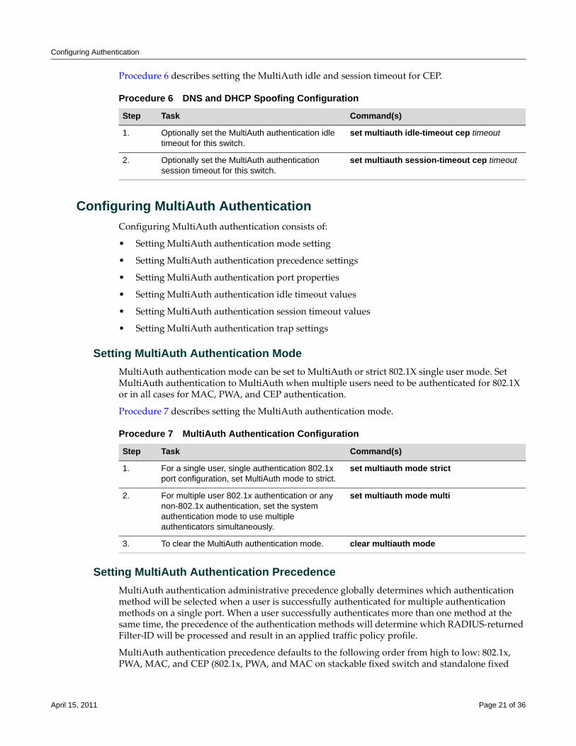
Procedure 6 describes setting the MultiAuth idle and session timeout for CEP.
Configuring MultiAuth AuthenticationConfiguring MultiAuth authentication consists of:
• Setting MultiAuth authentication mode setting
• Setting MultiAuth authentication precedence settings
• Setting MultiAuth authentication port properties
• Setting MultiAuth authentication idle timeout values
• Setting MultiAuth authentication session timeout values
• Setting MultiAuth authentication trap settings
Setting MultiAuth Authentication ModeMultiAuth authentication mode can be set to MultiAuth or strict 802.1X single user mode. Set MultiAuth authentication to MultiAuth when multiple users need to be authenticated for 802.1X or in all cases for MAC, PWA, and CEP authentication.
Procedure 7 describes setting the MultiAuth authentication mode.
Setting MultiAuth Authentication PrecedenceMultiAuth authentication administrative precedence globally determines which authentication method will be selected when a user is successfully authenticated for multiple authentication methods on a single port. When a user successfully authenticates more than one method at the same time, the precedence of the authentication methods will determine which RADIUS‐returned Filter‐ID will be processed and result in an applied traffic policy profile.
MultiAuth authentication precedence defaults to the following order from high to low: 802.1x, PWA, MAC, and CEP (802.1x, PWA, and MAC on stackable fixed switch and standalone fixed
Procedure 6 DNS and DHCP Spoofing Configuration
Step Task Command(s)
1. Optionally set the MultiAuth authentication idle timeout for this switch.
set multiauth idle-timeout cep timeout
2. Optionally set the MultiAuth authentication session timeout for this switch.
set multiauth session-timeout cep timeout
Procedure 7 MultiAuth Authentication Configuration
Step Task Command(s)
1. For a single user, single authentication 802.1x port configuration, set MultiAuth mode to strict.
set multiauth mode strict
2. For multiple user 802.1x authentication or any non-802.1x authentication, set the system authentication mode to use multiple authenticators simultaneously.
set multiauth mode multi
3. To clear the MultiAuth authentication mode. clear multiauth mode
April 15, 2011 Page 21 of 36
Configuring Authentication
switch devices). You may change the precedence for one or more methods by setting the authentication methods in the order of precedence from high to low. Any methods not entered are given a lower precedence than the methods entered in their pre‐existing order. For instance, if you start with the default order and only set PWA and MAC, the new precedence order will be PWA, MAC, 802.1x, and CEP.
Given the default order of precedence (802.1x, PWA, MAC, and CEP), if a user was to successfully authenticate with PWA and MAC, the authentication method RADIUS Filter‐ID applied would be PWA, because it has a higher position in the order. A MAC session would authenticate, but its associated RADIUS Filter‐ID would not be applied.
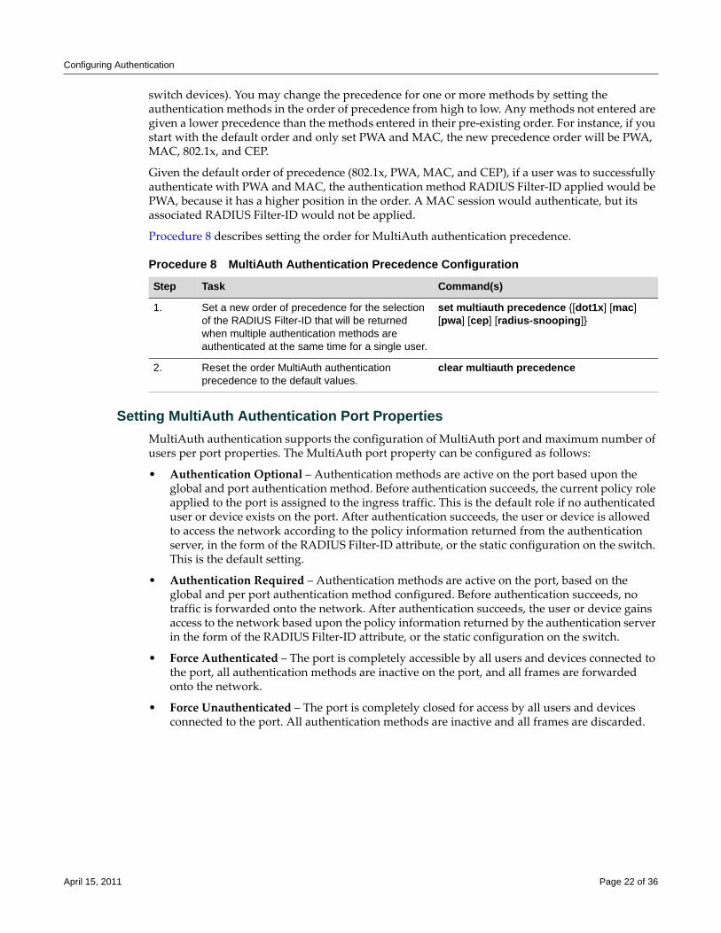
Procedure 8 describes setting the order for MultiAuth authentication precedence.
Setting MultiAuth Authentication Port PropertiesMultiAuth authentication supports the configuration of MultiAuth port and maximum number of users per port properties. The MultiAuth port property can be configured as follows:
• Authentication Optional – Authentication methods are active on the port based upon the global and port authentication method. Before authentication succeeds, the current policy role applied to the port is assigned to the ingress traffic. This is the default role if no authenticated user or device exists on the port. After authentication succeeds, the user or device is allowed to access the network according to the policy information returned from the authentication server, in the form of the RADIUS Filter‐ID attribute, or the static configuration on the switch. This is the default setting.
• Authentication Required – Authentication methods are active on the port, based on the global and per port authentication method configured. Before authentication succeeds, no traffic is forwarded onto the network. After authentication succeeds, the user or device gains access to the network based upon the policy information returned by the authentication server in the form of the RADIUS Filter‐ID attribute, or the static configuration on the switch.
• Force Authenticated – The port is completely accessible by all users and devices connected to the port, all authentication methods are inactive on the port, and all frames are forwarded onto the network.
• Force Unauthenticated – The port is completely closed for access by all users and devices connected to the port. All authentication methods are inactive and all frames are discarded.
Procedure 8 MultiAuth Authentication Precedence Configuration
Step Task Command(s)
1. Set a new order of precedence for the selection of the RADIUS Filter-ID that will be returned when multiple authentication methods are authenticated at the same time for a single user.
set multiauth precedence {[dot1x] [mac] [pwa] [cep] [radius-snooping]}
2. Reset the order MultiAuth authentication precedence to the default values.
clear multiauth precedence
April 15, 2011 Page 22 of 36
Configuring Authentication
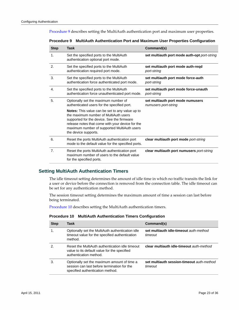
Procedure 9 describes setting the MultiAuth authentication port and maximum user properties.
Setting MultiAuth Authentication TimersThe idle timeout setting determines the amount of idle time in which no traffic transits the link for a user or device before the connection is removed from the connection table. The idle timeout can be set for any authentication method.
The session timeout setting determines the maximum amount of time a session can last before being terminated.
Procedure 10 describes setting the MultiAuth authentication timers.
Procedure 9 MultiAuth Authentication Port and Maximum User Properties Configuration
Step Task Command(s)
1. Set the specified ports to the MultiAuth authentication optional port mode.
set multiauth port mode auth-opt port-string
2. Set the specified ports to the MultiAuth authentication required port mode.
set multiauth port mode auth-reqd port-string
3. Set the specified ports to the MultiAuth authentication force authenticated port mode.
set multiauth port mode force-auth port-string
4. Set the specified ports to the MultiAuth authentication force unauthenticated port mode.
set multiauth port mode force-unauth port-string
5. Optionally set the maximum number of authenticated users for the specified port.
Notes: This value can be set to any value up to the maximum number of MultiAuth users supported for the device. See the firmware release notes that come with your device for the maximum number of supported MultiAuth users the device supports.
set multiauth port mode numusers numusers port-string
6. Reset the ports MultiAuth authentication port mode to the default value for the specified ports.
clear multiauth port mode port-string
7. Reset the ports MultiAuth authentication port maximum number of users to the default value for the specified ports.
clear multiauth port numusers port-string
Procedure 10 MultiAuth Authentication Timers Configuration
Step Task Command(s)
1. Optionally set the MultiAuth authentication idle timeout value for the specified authentication method.
set multiauth idle-timeout auth-method timeout
2. Reset the MultiAuth authentication idle timeout value to its default value for the specified authentication method.
clear multiauth idle-timeout auth-method
3. Optionally set the maximum amount of time a session can last before termination for the specified authentication method.
set multiauth session-timeout auth-method timeout
April 15, 2011 Page 23 of 36
Configuring Authentication
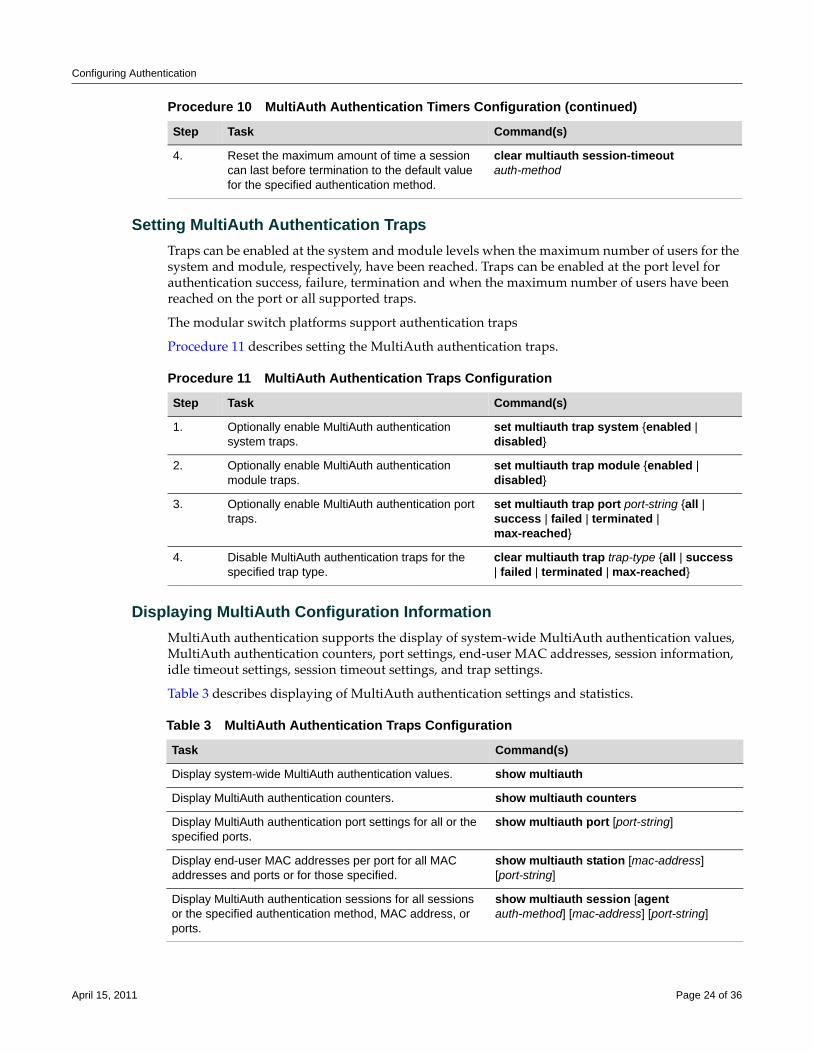
Setting MultiAuth Authentication TrapsTraps can be enabled at the system and module levels when the maximum number of users for the system and module, respectively, have been reached. Traps can be enabled at the port level for authentication success, failure, termination and when the maximum number of users have been reached on the port or all supported traps.
The modular switch platforms support authentication traps
Procedure 11 describes setting the MultiAuth authentication traps.
Displaying MultiAuth Configuration InformationMultiAuth authentication supports the display of system‐wide MultiAuth authentication values, MultiAuth authentication counters, port settings, end‐user MAC addresses, session information, idle timeout settings, session timeout settings, and trap settings.
Table 3 describes displaying of MultiAuth authentication settings and statistics.
4. Reset the maximum amount of time a session can last before termination to the default value for the specified authentication method.
clear multiauth session-timeout auth-method
Procedure 10 MultiAuth Authentication Timers Configuration (continued)
Step Task Command(s)
Procedure 11 MultiAuth Authentication Traps Configuration
Step Task Command(s)
1. Optionally enable MultiAuth authentication system traps.
set multiauth trap system {enabled | disabled}
2. Optionally enable MultiAuth authentication module traps.
set multiauth trap module {enabled | disabled}
3. Optionally enable MultiAuth authentication port traps.
set multiauth trap port port-string {all | success | failed | terminated | max-reached}
4. Disable MultiAuth authentication traps for the specified trap type.
clear multiauth trap trap-type {all | success | failed | terminated | max-reached}
Table 3 MultiAuth Authentication Traps Configuration
Task Command(s)
Display system-wide MultiAuth authentication values. show multiauth
Display MultiAuth authentication counters. show multiauth counters
Display MultiAuth authentication port settings for all or the specified ports.
show multiauth port [port-string]
Display end-user MAC addresses per port for all MAC addresses and ports or for those specified.
show multiauth station [mac-address] [port-string]
Display MultiAuth authentication sessions for all sessions or the specified authentication method, MAC address, or ports.
show multiauth session [agent auth-method] [mac-address] [port-string]
April 15, 2011 Page 24 of 36
Configuring Authentication
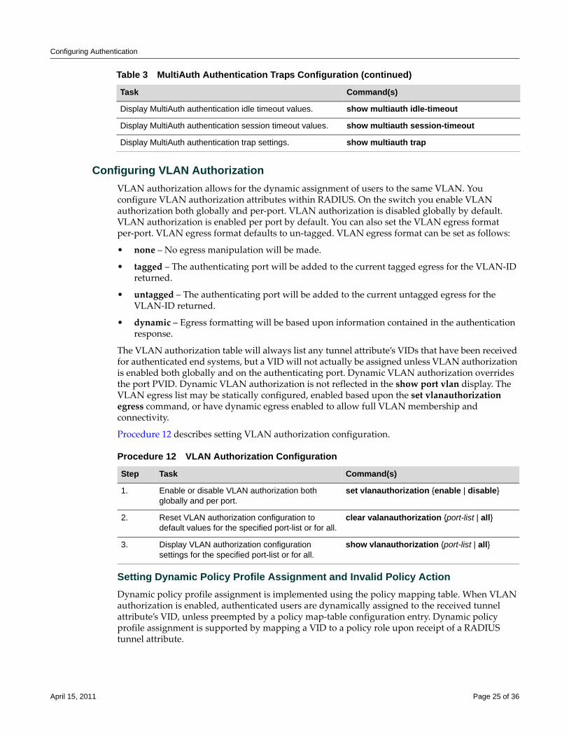
Configuring VLAN AuthorizationVLAN authorization allows for the dynamic assignment of users to the same VLAN. You configure VLAN authorization attributes within RADIUS. On the switch you enable VLAN authorization both globally and per‐port. VLAN authorization is disabled globally by default. VLAN authorization is enabled per port by default. You can also set the VLAN egress format per‐port. VLAN egress format defaults to un‐tagged. VLAN egress format can be set as follows:
• none – No egress manipulation will be made.
• tagged – The authenticating port will be added to the current tagged egress for the VLAN‐ID returned.
• untagged – The authenticating port will be added to the current untagged egress for the VLAN‐ID returned.
• dynamic – Egress formatting will be based upon information contained in the authentication response.
The VLAN authorization table will always list any tunnel attribute’s VIDs that have been received for authenticated end systems, but a VID will not actually be assigned unless VLAN authorization is enabled both globally and on the authenticating port. Dynamic VLAN authorization overrides the port PVID. Dynamic VLAN authorization is not reflected in the show port vlan display. The VLAN egress list may be statically configured, enabled based upon the set vlanauthorization egress command, or have dynamic egress enabled to allow full VLAN membership and connectivity.
Procedure 12 describes setting VLAN authorization configuration.
Setting Dynamic Policy Profile Assignment and Invalid Policy Action Dynamic policy profile assignment is implemented using the policy mapping table. When VLAN authorization is enabled, authenticated users are dynamically assigned to the received tunnel attribute’s VID, unless preempted by a policy map‐table configuration entry. Dynamic policy profile assignment is supported by mapping a VID to a policy role upon receipt of a RADIUS tunnel attribute.
Display MultiAuth authentication idle timeout values. show multiauth idle-timeout
Display MultiAuth authentication session timeout values. show multiauth session-timeout
Display MultiAuth authentication trap settings. show multiauth trap
Table 3 MultiAuth Authentication Traps Configuration (continued)
Task Command(s)
Procedure 12 VLAN Authorization Configuration
Step Task Command(s)
1. Enable or disable VLAN authorization both globally and per port.
set vlanauthorization {enable | disable}
2. Reset VLAN authorization configuration to default values for the specified port-list or for all.
clear valanauthorization {port-list | all}
3. Display VLAN authorization configuration settings for the specified port-list or for all.
show vlanauthorization {port-list | all}
April 15, 2011 Page 25 of 36
Configuring Authentication
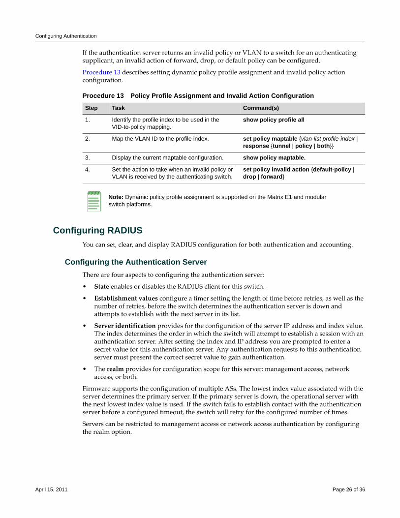
If the authentication server returns an invalid policy or VLAN to a switch for an authenticating supplicant, an invalid action of forward, drop, or default policy can be configured.
Procedure 13 describes setting dynamic policy profile assignment and invalid policy action configuration.
Configuring RADIUSYou can set, clear, and display RADIUS configuration for both authentication and accounting.
Configuring the Authentication ServerThere are four aspects to configuring the authentication server:
• State enables or disables the RADIUS client for this switch.
• Establishment values configure a timer setting the length of time before retries, as well as the number of retries, before the switch determines the authentication server is down and attempts to establish with the next server in its list.
• Server identification provides for the configuration of the server IP address and index value. The index determines the order in which the switch will attempt to establish a session with an authentication server. After setting the index and IP address you are prompted to enter a secret value for this authentication server. Any authentication requests to this authentication server must present the correct secret value to gain authentication.
• The realm provides for configuration scope for this server: management access, network access, or both.
Firmware supports the configuration of multiple ASs. The lowest index value associated with the server determines the primary server. If the primary server is down, the operational server with the next lowest index value is used. If the switch fails to establish contact with the authentication server before a configured timeout, the switch will retry for the configured number of times.
Servers can be restricted to management access or network access authentication by configuring the realm option.
Procedure 13 Policy Profile Assignment and Invalid Action Configuration
Step Task Command(s)
1. Identify the profile index to be used in the VID-to-policy mapping.
show policy profile all
2. Map the VLAN ID to the profile index. set policy maptable {vlan-list profile-index | response {tunnel | policy | both}}
3. Display the current maptable configuration. show policy maptable.
4. Set the action to take when an invalid policy or VLAN is received by the authenticating switch.
set policy invalid action {default-policy | drop | forward}
Note: Dynamic policy profile assignment is supported on the Matrix E1 and modular switch platforms.
April 15, 2011 Page 26 of 36
Configuring Authentication
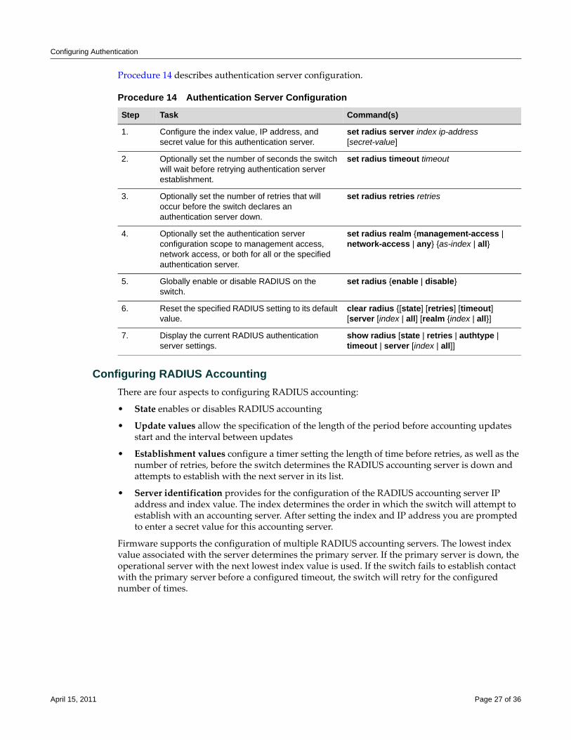
Procedure 14 describes authentication server configuration.
Configuring RADIUS AccountingThere are four aspects to configuring RADIUS accounting:
• State enables or disables RADIUS accounting
• Update values allow the specification of the length of the period before accounting updates start and the interval between updates
• Establishment values configure a timer setting the length of time before retries, as well as the number of retries, before the switch determines the RADIUS accounting server is down and attempts to establish with the next server in its list.
• Server identification provides for the configuration of the RADIUS accounting server IP address and index value. The index determines the order in which the switch will attempt to establish with an accounting server. After setting the index and IP address you are prompted to enter a secret value for this accounting server.
Firmware supports the configuration of multiple RADIUS accounting servers. The lowest index value associated with the server determines the primary server. If the primary server is down, the operational server with the next lowest index value is used. If the switch fails to establish contact with the primary server before a configured timeout, the switch will retry for the configured number of times.
Procedure 14 Authentication Server Configuration
Step Task Command(s)
1. Configure the index value, IP address, and secret value for this authentication server.
set radius server index ip-address [secret-value]
2. Optionally set the number of seconds the switch will wait before retrying authentication server establishment.
set radius timeout timeout
3. Optionally set the number of retries that will occur before the switch declares an authentication server down.
set radius retries retries
4. Optionally set the authentication server configuration scope to management access, network access, or both for all or the specified authentication server.
set radius realm {management-access | network-access | any} {as-index | all}
5. Globally enable or disable RADIUS on the switch.
set radius {enable | disable}
6. Reset the specified RADIUS setting to its default value.
clear radius {[state] [retries] [timeout] [server [index | all] [realm {index | all}]
7. Display the current RADIUS authentication server settings.
show radius [state | retries | authtype | timeout | server [index | all]]
April 15, 2011 Page 27 of 36
Configuring Authentication
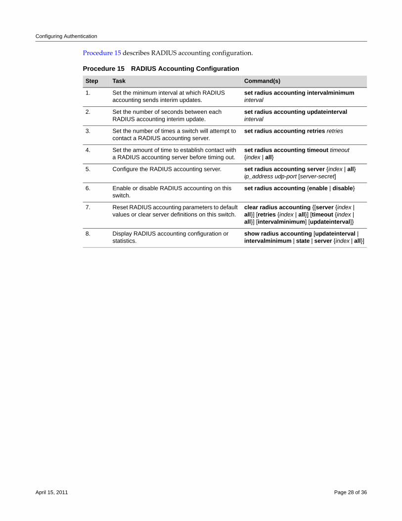
Procedure 15 describes RADIUS accounting configuration.
Procedure 15 RADIUS Accounting Configuration
Step Task Command(s)
1. Set the minimum interval at which RADIUS accounting sends interim updates.
set radius accounting intervalminimum interval
2. Set the number of seconds between each RADIUS accounting interim update.
set radius accounting updateinterval interval
3. Set the number of times a switch will attempt to contact a RADIUS accounting server.
set radius accounting retries retries
4. Set the amount of time to establish contact with a RADIUS accounting server before timing out.
set radius accounting timeout timeout {index | all}
5. Configure the RADIUS accounting server. set radius accounting server {index | all} ip_address udp-port [server-secret]
6. Enable or disable RADIUS accounting on this switch.
set radius accounting {enable | disable}
7. Reset RADIUS accounting parameters to default values or clear server definitions on this switch.
clear radius accounting {[server {index | all}] [retries {index | all}] [timeout {index | all}] [intervalminimum] [updateinterval]}
8. Display RADIUS accounting configuration or statistics.
show radius accounting [updateinterval | intervalminimum | state | server {index | all}]
April 15, 2011 Page 28 of 36
Authentication Configuration Example
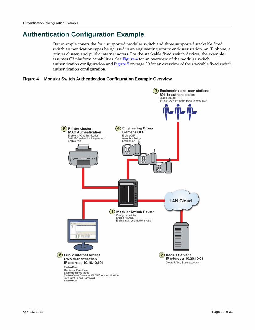
Authentication Configuration ExampleOur example covers the four supported modular switch and three supported stackable fixed switch authentication types being used in an engineering group: end‐user station, an IP phone, a printer cluster, and public internet access. For the stackable fixed switch devices, the example assumes C3 platform capabilities. See Figure 4 for an overview of the modular switch authentication configuration and Figure 5 on page 30 for an overview of the stackable fixed switch authentication configuration.
Figure 4 Modular Switch Authentication Configuration Example Overview
1 Modular Switch RouterConfigure policiesEnable RADIUSEnable multi-user authentication
4 Engineering GroupSiemens CEPEnable CEPAssociate PolicyEnable Port
5 Printer clusterMAC AuthenticationEnable MAC authenticationSet MAC authentication passwordEnable Port
3 Engineering end-user stations801.1x authenticationEnable 802.1xSet non-Authentication ports to force-auth
6 Public internet accessPWA AuthenticationIP address: 10.10.10.101Enable PWAConfigure IP addressEnable Enhance ModeEnable Guest Status for RADIUS AuthentificationSet Guest ID and PasswordEnable Port
LAN Cloud
2 Radius Server 1IP address: 10.20.10.01 Create RADIUS user accounts
April 15, 2011 Page 29 of 36
Authentication Configuration Example
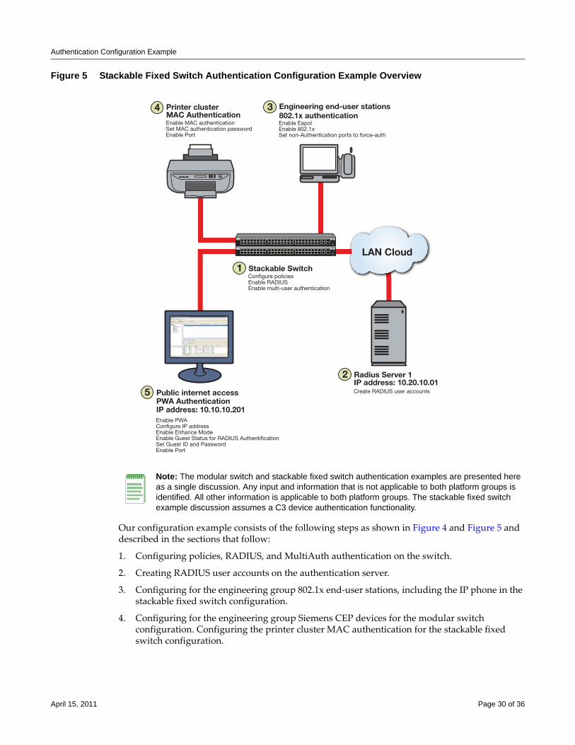
Figure 5 Stackable Fixed Switch Authentication Configuration Example Overview
Our configuration example consists of the following steps as shown in Figure 4 and Figure 5 and described in the sections that follow:
1. Configuring policies, RADIUS, and MultiAuth authentication on the switch.
2. Creating RADIUS user accounts on the authentication server.
3. Configuring for the engineering group 802.1x end‐user stations, including the IP phone in the stackable fixed switch configuration.
4. Configuring for the engineering group Siemens CEP devices for the modular switch configuration. Configuring the printer cluster MAC authentication for the stackable fixed switch configuration.
1 Stackable SwitchConfigure policiesEnable RADIUSEnable multi-user authentication
4 Printer clusterMAC AuthenticationEnable MAC authenticationSet MAC authentication passwordEnable Port
3 Engineering end-user stations802.1x authenticationEnable EapolEnable 802.1xSet non-Authentication ports to force-auth
5 Public internet accessPWA AuthenticationIP address: 10.10.10.201Enable PWAConfigure IP addressEnable Enhance ModeEnable Guest Status for RADIUS AuthentificationSet Guest ID and PasswordEnable Port
LAN Cloud
2 Radius Server 1IP address: 10.20.10.01 Create RADIUS user accounts
Note: The modular switch and stackable fixed switch authentication examples are presented here as a single discussion. Any input and information that is not applicable to both platform groups is identified. All other information is applicable to both platform groups. The stackable fixed switch example discussion assumes a C3 device authentication functionality.
April 15, 2011 Page 30 of 36
Authentication Configuration Example
5. Configuring the printer cluster MAC authentication for the modular switch configuration. Configuring the public area internet access for PWA for the stackable fixed switch.
6. Configuring for the public area internet access for PWA for the modular switch.
Configuring MultiAuth AuthenticationMultiAuth authentication must be set to multi whenever multiple users of 802.1x need to be authenticated or whenever any MAC‐based, PWA, or CEP authentication is present. For ports where no authentication is present, such as switch to switch, or switch to router connections, you should also set MultiAuth port mode to force authenticate to assure that traffic is not blocked by a failed authentication. For purposes of this example, we will limit authentication to a maximum of 6 users per port.
The following CLI input:
• Sets MultiAuth authentication to multi.
• Sets ports with switch to switch and switch to router connections to force authenticate.
• Sets the maximum number of users that can authenticate on each port to 6.
System(rw)->set multiauth mode multi
System(rw)->set multiauth port mode force-auth ge.1.5-7
System(rw)->set multiauth port numusers 6 ge.1.5-7
System(rw)->set multiauth port mode force-auth ge.1.19-24
System(rw)->set multiauth port numusers 6 ge.1.19-24
• Enables MultiAuth authentication system and module traps for the modular switch configuration.
System(rw)->set multiauth trap system enabled
System(rw)->set multiauth trap module enabled
This completes the MultiAuth authentication configuration piece for this example. Keep in mind that you would want to use the set multiauth precedence command, to specify which authentication method should take precedence, should you have a single user configured for multiple authentications on the same port.
Enabling RADIUS On the SwitchThe switch needs to be informed about the authentication server. Use the following CLI input to
• Configure the authentication server IP address on the switch.
• Enable the RADIUS server.
System(rw)->set radius server 1 10.20.10.01
System(rw)->set radius enable
Creating RADIUS User Accounts On The Authentication ServerRADIUS account creation on the authentication server is specific to the RADIUS application you are using. Please see the documentation that comes with your RADIUS application. Create an account for all users to be authenticated.
April 15, 2011 Page 31 of 36
Authentication Configuration Example
Configuring the Engineering Group 802.1x End-User StationsThere are three aspects to configuring 802.1x for the engineering group:
• Configure EAP on each end‐user station.
• Set up an account in RADIUS on the authentication server for each end‐user station.
• Configure 802.1x on the switch.
Configuring EAP on the end‐user station and setting up the RADIUS account for each station is dependent upon your operating system and the RADIUS application being used, respectively. The important thing the network administrator should keep in mind is that these two configurations should be in place before moving on to the 802.1x configuration on the switch. In an 802.1x configuration, policy is specified in the RADIUS account configuration on the authentication server using the RADIUS Filter‐ID. See “The RADIUS Filter‐ID” on page 9 for RADIUS Filter‐ID information. If a RADIUS Filter‐ID exists for the user account, the RADIUS protocol returns it in the RADIUS Accept message and the firmware applies the policy to the user.
The following CLI input:
• Enables EAP on the stackable fixed switch
C3(rw)->set eapol enable
• Enables 802.1x on the switch
• Sets port‐control to forced‐auth for all connections between switches and routers, because they do not use authentication and would be blocked if not set to forced‐auth.
System(rw)->set dot1x enable
System(rw)->set dot1x auth-config authcontrolled-portcontrol forced-auth ge.1.5
System(rw)->set dot1x auth-config authcontrolled-portcontrol forced-auth
ge.1.19
System(rw)->set dot1x auth-config authcontrolled-portcontrol forced-auth
ge.2.24
This completes the 802.1x end‐user stations configuration.
Configuring the Engineering Group Siemens CEP Devices
If a Siemens phone is inserted into a port enabled for Siemens CEP, the firmware detects communication on UDP/TCP port 4060. Use policy manager to configure a policy with a VLAN, CoS, and rate limit appropriate to VoIP. See the QoS Feature Guide Configuration Example section at: https://extranet.enterasys.com/downloads for a QoS VoIP policy configuration example. Once an existing policy is configured, the set cep policy command can be used to apply the policy.
Note: Globally enabling 802.1x on a switch sets the port-control type to auto for all ports. Be sure to set port-control to forced-auth on all ports that will not be authenticating using 802.1x and no other authentication method is configured. Otherwise these ports will fail authentication and traffic will be blocked.
Note: CEP is supported on the modular switch platforms. Stackable fixed switch platforms authenticate IP phone devices using either 802.1x or MAC authentication. 802.1x is used in this stackable fixed switch authentication example for the IP phone implementation.
April 15, 2011 Page 32 of 36
Authentication Configuration Example
The following CLI input:
• Enables CEP globally on the switch.
• Sets CEP policy to a previously configured policy named siemens with an index of 9.
• Sets ports ge.1.16‐18 to only accept default Siemens type phones and applies the Siemens policy to the specified ports.
System(rw)->set cep enable
System(rw)->set cep policy siemens 9
System(rw)->set cep port ge.1.16-18 siemens enable
This completes the Siemens CEP end‐user stations configuration.
Configuring the Printer Cluster for MAC-Based AuthenticationPerform the following tasks to configure MAC‐based authentication for the printer cluster in our example:
• Set up an account for each printer on the authentication server that contains the printer MAC address, the MAC authentication password configured on the switch, and a RADIUS Filter‐ID entry specifying the printer policy.
• Configure a policy using the policy manager specifying the printer cluster VLAN and optionally configuring a CoS and rate limit.
• Enable MAC authentication globally on the switch.
• Enter the MAC authentication password as enterasys on the switch.
• Set the MAC authentication significant‐bits to 24.
• Enable MAC authentication on the ports used by the printer cluster: ge.1.3‐4
With the authentication server configured with a RADIUS account for each printer, and the printer policy preconfigured, enter the following CLI input:
System(rw)->set macauthentication enable
System(rw)->set macauthentication password enterasys
System(rw)->set macauthentication significant-bits 24
System(rw)->set macauthentication port enable ge.1.3-4
This completes the printer cluster MAC authentication configuration.
Configuring the Public Area PWA StationThe public area PWA station provides visitors to your business site with open access to the internet, while at the same time isolating the station from any access to your internal network. In order to provide a default set of network resources to communicate over HTTP, policy must be set to only allow DHCP, ARP, DNS, and HTTP. You may want to set a rate limit that would guard against excessive streaming. You will also need to set up RADIUS for the public station account on the authentication server. This configuration will include the guest name, password, and a RADIUS Filter‐ID for the public policy.
Perform the following tasks to configure the public station for PWA authentication:
• Configure the policy appropriate to the public station.
April 15, 2011 Page 33 of 36
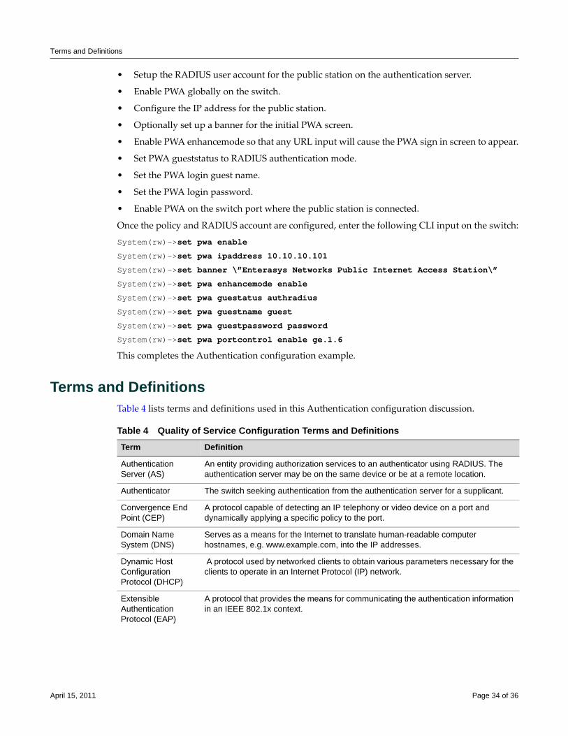
Terms and Definitions
• Setup the RADIUS user account for the public station on the authentication server.
• Enable PWA globally on the switch.
• Configure the IP address for the public station.
• Optionally set up a banner for the initial PWA screen.
• Enable PWA enhancemode so that any URL input will cause the PWA sign in screen to appear.
• Set PWA gueststatus to RADIUS authentication mode.
• Set the PWA login guest name.
• Set the PWA login password.
• Enable PWA on the switch port where the public station is connected.
Once the policy and RADIUS account are configured, enter the following CLI input on the switch:
System(rw)->set pwa enable
System(rw)->set pwa ipaddress 10.10.10.101
System(rw)->set banner \”Enterasys Networks Public Internet Access Station\”
System(rw)->set pwa enhancemode enable
System(rw)->set pwa guestatus authradius
System(rw)->set pwa guestname guest
System(rw)->set pwa guestpassword password
System(rw)->set pwa portcontrol enable ge.1.6
This completes the Authentication configuration example.
Terms and DefinitionsTable 4 lists terms and definitions used in this Authentication configuration discussion.
Table 4 Quality of Service Configuration Terms and Definitions Term Definition
Authentication Server (AS)
An entity providing authorization services to an authenticator using RADIUS. The authentication server may be on the same device or be at a remote location.
Authenticator The switch seeking authentication from the authentication server for a supplicant.
Convergence End Point (CEP)
A protocol capable of detecting an IP telephony or video device on a port and dynamically applying a specific policy to the port.
Domain Name System (DNS)
Serves as a means for the Internet to translate human-readable computer hostnames, e.g. www.example.com, into the IP addresses.
Dynamic Host Configuration Protocol (DHCP)
A protocol used by networked clients to obtain various parameters necessary for the clients to operate in an Internet Protocol (IP) network.
Extensible Authentication Protocol (EAP)
A protocol that provides the means for communicating the authentication information in an IEEE 802.1x context.
April 15, 2011 Page 34 of 36
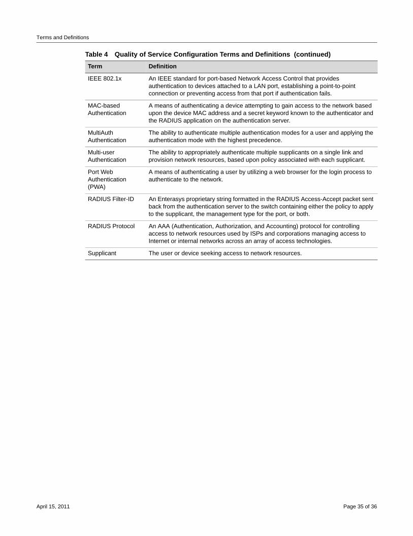
Terms and Definitions
IEEE 802.1x An IEEE standard for port-based Network Access Control that provides authentication to devices attached to a LAN port, establishing a point-to-point connection or preventing access from that port if authentication fails.
MAC-based Authentication
A means of authenticating a device attempting to gain access to the network based upon the device MAC address and a secret keyword known to the authenticator and the RADIUS application on the authentication server.
MultiAuth Authentication
The ability to authenticate multiple authentication modes for a user and applying the authentication mode with the highest precedence.
Multi-user Authentication
The ability to appropriately authenticate multiple supplicants on a single link and provision network resources, based upon policy associated with each supplicant.
Port Web Authentication (PWA)
A means of authenticating a user by utilizing a web browser for the login process to authenticate to the network.
RADIUS Filter-ID An Enterasys proprietary string formatted in the RADIUS Access-Accept packet sent back from the authentication server to the switch containing either the policy to apply to the supplicant, the management type for the port, or both.
RADIUS Protocol An AAA (Authentication, Authorization, and Accounting) protocol for controlling access to network resources used by ISPs and corporations managing access to Internet or internal networks across an array of access technologies.
Supplicant The user or device seeking access to network resources.
Table 4 Quality of Service Configuration Terms and Definitions (continued)Term Definition
April 15, 2011 Page 35 of 36
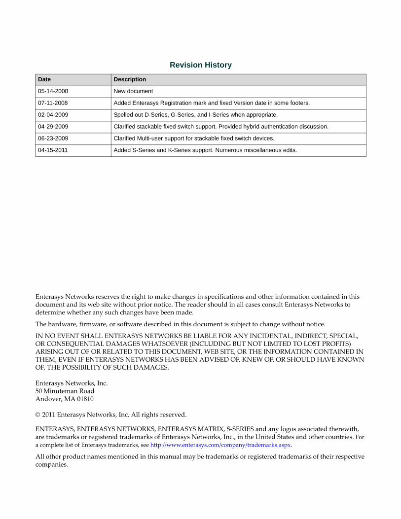
Enterasys Networks reserves the right to make changes in specifications and other information contained in this document and its web site without prior notice. The reader should in all cases consult Enterasys Networks to determine whether any such changes have been made.
The hardware, firmware, or software described in this document is subject to change without notice.
IN NO EVENT SHALL ENTERASYS NETWORKS BE LIABLE FOR ANY INCIDENTAL, INDIRECT, SPECIAL, OR CONSEQUENTIAL DAMAGES WHATSOEVER (INCLUDING BUT NOT LIMITED TO LOST PROFITS) ARISING OUT OF OR RELATED TO THIS DOCUMENT, WEB SITE, OR THE INFORMATION CONTAINED IN THEM, EVEN IF ENTERASYS NETWORKS HAS BEEN ADVISED OF, KNEW OF, OR SHOULD HAVE KNOWN OF, THE POSSIBILITY OF SUCH DAMAGES.
Enterasys Networks, Inc.50 Minuteman RoadAndover, MA 01810
© 2011 Enterasys Networks, Inc. All rights reserved.
ENTERASYS, ENTERASYS NETWORKS, ENTERASYS MATRIX, S‐SERIES and any logos associated therewith, are trademarks or registered trademarks of Enterasys Networks, Inc., in the United States and other countries. For a complete list of Enterasys trademarks, see http://www.enterasys.com/company/trademarks.aspx.
All other product names mentioned in this manual may be trademarks or registered trademarks of their respective companies.
Revision History
Date Description
05-14-2008 New document
07-11-2008 Added Enterasys Registration mark and fixed Version date in some footers.
02-04-2009 Spelled out D-Series, G-Series, and I-Series when appropriate.
04-29-2009 Clarified stackable fixed switch support. Provided hybrid authentication discussion.
06-23-2009 Clarified Multi-user support for stackable fixed switch devices.
04-15-2011 Added S-Series and K-Series support. Numerous miscellaneous edits.
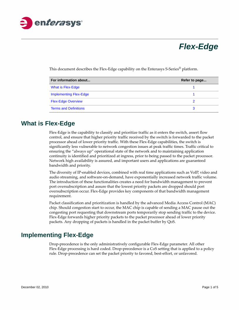
Flex-Edge
This document describes the Flex‐Edge capability on the Enterasys S‐Series® platform.
What is Flex-EdgeFlex‐Edge is the capability to classify and prioritize traffic as it enters the switch, assert flow control, and ensure that higher priority traffic received by the switch is forwarded to the packet processor ahead of lower priority traffic. With these Flex‐Edge capabilities, the switch is significantly less vulnerable to network congestion issues at peak traffic times. Traffic critical to ensuring the “always up” operational state of the network and to maintaining application continuity is identified and prioritized at ingress, prior to being passed to the packet processor. Network high availability is assured, and important users and applications are guaranteed bandwidth and priority.
The diversity of IP‐enabled devices, combined with real time applications such as VoIP, video and audio streaming, and software‐on‐demand, have exponentially increased network traffic volume. The introduction of these functionalities creates a need for bandwidth management to prevent port oversubscription and assure that the lowest priority packets are dropped should port oversubscription occur. Flex‐Edge provides key components of that bandwidth management requirement.
Packet classification and prioritization is handled by the advanced Media Access Control (MAC) chip. Should congestion start to occur, the MAC chip is capable of sending a MAC pause out the congesting port requesting that downstream ports temporarily stop sending traffic to the device. Flex‐Edge forwards higher priority packets to the packet processor ahead of lower priority packets. Any dropping of packets is handled in the packet buffer by QoS.
Implementing Flex-EdgeDrop‐precedence is the only administratively configurable Flex‐Edge parameter. All other Flex‐Edge processing is hard coded. Drop‐precedence is a CoS setting that is applied to a policy rule. Drop‐precedence can set the packet priority to favored, best‐effort, or unfavored.
For information about... Refer to page...
What is Flex-Edge 1
Implementing Flex-Edge 1
Flex-Edge Overview 2
Terms and Definitions 3
December 02, 2010 Page 1 of 5
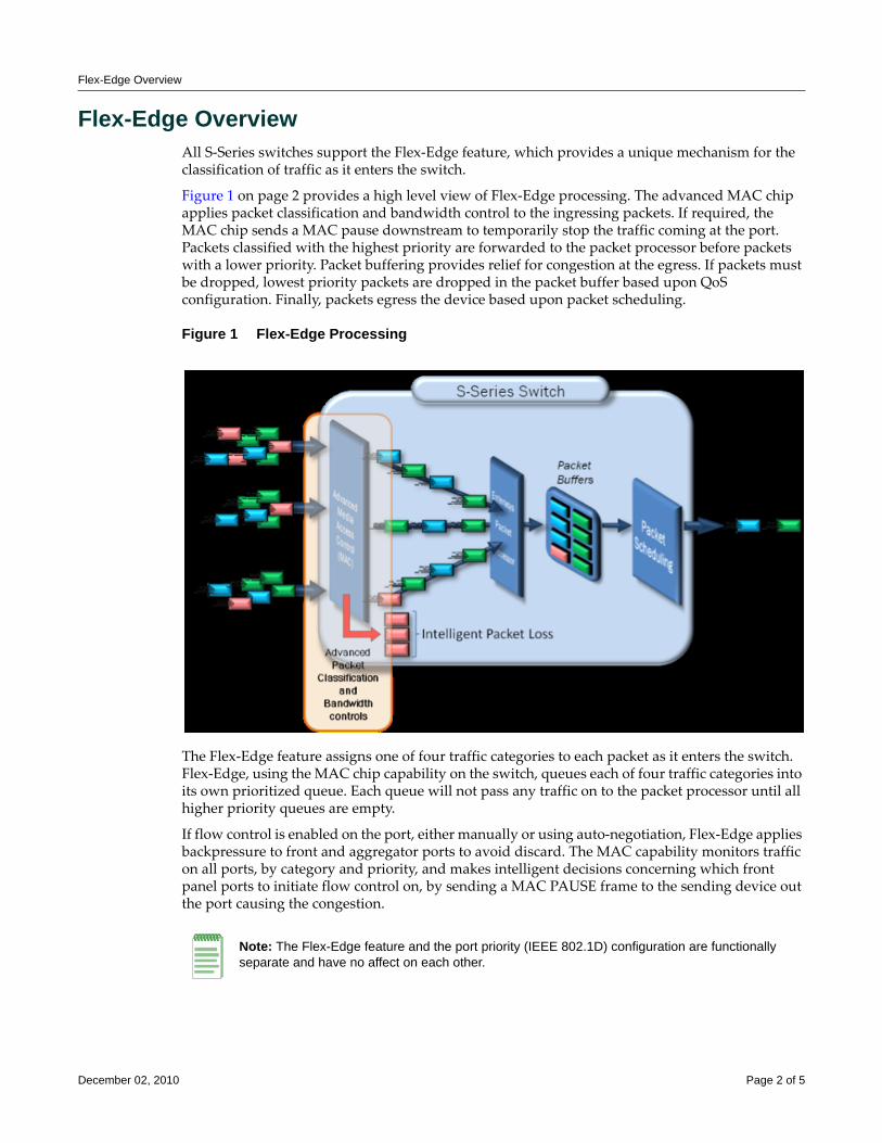
Flex-Edge Overview
Flex-Edge OverviewAll S‐Series switches support the Flex‐Edge feature, which provides a unique mechanism for the classification of traffic as it enters the switch.
Figure 1 on page 2 provides a high level view of Flex‐Edge processing. The advanced MAC chip applies packet classification and bandwidth control to the ingressing packets. If required, the MAC chip sends a MAC pause downstream to temporarily stop the traffic coming at the port. Packets classified with the highest priority are forwarded to the packet processor before packets with a lower priority. Packet buffering provides relief for congestion at the egress. If packets must be dropped, lowest priority packets are dropped in the packet buffer based upon QoS configuration. Finally, packets egress the device based upon packet scheduling.
Figure 1 Flex-Edge Processing
The Flex‐Edge feature assigns one of four traffic categories to each packet as it enters the switch. Flex‐Edge, using the MAC chip capability on the switch, queues each of four traffic categories into its own prioritized queue. Each queue will not pass any traffic on to the packet processor until all higher priority queues are empty.
If flow control is enabled on the port, either manually or using auto‐negotiation, Flex‐Edge applies backpressure to front and aggregator ports to avoid discard. The MAC capability monitors traffic on all ports, by category and priority, and makes intelligent decisions concerning which front panel ports to initiate flow control on, by sending a MAC PAUSE frame to the sending device out the port causing the congestion.
Note: The Flex-Edge feature and the port priority (IEEE 802.1D) configuration are functionally separate and have no affect on each other.
December 02, 2010 Page 2 of 5
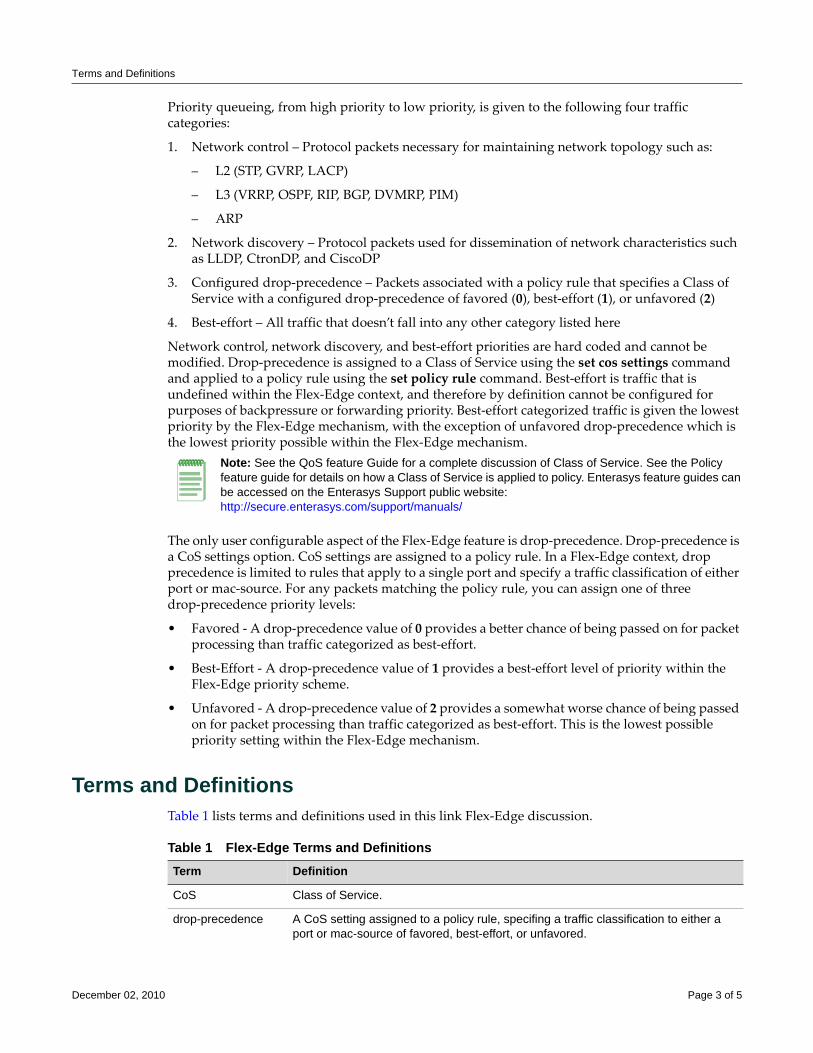
Terms and Definitions
Priority queueing, from high priority to low priority, is given to the following four traffic categories:
1. Network control – Protocol packets necessary for maintaining network topology such as:
– L2 (STP, GVRP, LACP)
– L3 (VRRP, OSPF, RIP, BGP, DVMRP, PIM)
– ARP
2. Network discovery – Protocol packets used for dissemination of network characteristics such as LLDP, CtronDP, and CiscoDP
3. Configured drop‐precedence – Packets associated with a policy rule that specifies a Class of Service with a configured drop‐precedence of favored (0), best‐effort (1), or unfavored (2)
4. Best‐effort – All traffic that doesn’t fall into any other category listed here
Network control, network discovery, and best‐effort priorities are hard coded and cannot be modified. Drop‐precedence is assigned to a Class of Service using the set cos settings command and applied to a policy rule using the set policy rule command. Best‐effort is traffic that is undefined within the Flex‐Edge context, and therefore by definition cannot be configured for purposes of backpressure or forwarding priority. Best‐effort categorized traffic is given the lowest priority by the Flex‐Edge mechanism, with the exception of unfavored drop‐precedence which is the lowest priority possible within the Flex‐Edge mechanism.
The only user configurable aspect of the Flex‐Edge feature is drop‐precedence. Drop‐precedence is a CoS settings option. CoS settings are assigned to a policy rule. In a Flex‐Edge context, drop precedence is limited to rules that apply to a single port and specify a traffic classification of either port or mac‐source. For any packets matching the policy rule, you can assign one of three drop‐precedence priority levels:
• Favored ‐ A drop‐precedence value of 0 provides a better chance of being passed on for packet processing than traffic categorized as best‐effort.
• Best‐Effort ‐ A drop‐precedence value of 1 provides a best‐effort level of priority within the Flex‐Edge priority scheme.
• Unfavored ‐ A drop‐precedence value of 2 provides a somewhat worse chance of being passed on for packet processing than traffic categorized as best‐effort. This is the lowest possible priority setting within the Flex‐Edge mechanism.
Terms and DefinitionsTable 1 lists terms and definitions used in this link Flex‐Edge discussion.
Note: See the QoS feature Guide for a complete discussion of Class of Service. See the Policy feature guide for details on how a Class of Service is applied to policy. Enterasys feature guides can be accessed on the Enterasys Support public website: http://secure.enterasys.com/support/manuals/
Table 1 Flex-Edge Terms and Definitions Term Definition
CoS Class of Service.
drop-precedence A CoS setting assigned to a policy rule, specifing a traffic classification to either a port or mac-source of favored, best-effort, or unfavored.
December 02, 2010 Page 3 of 5
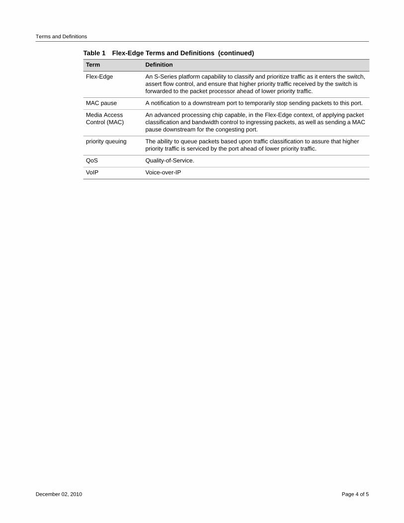
Terms and Definitions
Flex-Edge An S-Series platform capability to classify and prioritize traffic as it enters the switch, assert flow control, and ensure that higher priority traffic received by the switch is forwarded to the packet processor ahead of lower priority traffic.
MAC pause A notification to a downstream port to temporarily stop sending packets to this port.
Media Access Control (MAC)
An advanced processing chip capable, in the Flex-Edge context, of applying packet classification and bandwidth control to ingressing packets, as well as sending a MAC pause downstream for the congesting port.
priority queuing The ability to queue packets based upon traffic classification to assure that higher priority traffic is serviced by the port ahead of lower priority traffic.
QoS Quality-of-Service.
VoIP Voice-over-IP
Table 1 Flex-Edge Terms and Definitions (continued)Term Definition
December 02, 2010 Page 4 of 5
Revision History
Enterasys Networks reserves the right to make changes in specifications and other information contained in this document and its web site without prior notice. The reader should in all cases consult Enterasys Networks to determine whether any such changes have been made.
The hardware, firmware, or software described in this document is subject to change without notice.
IN NO EVENT SHALL ENTERASYS NETWORKS BE LIABLE FOR ANY INCIDENTAL, INDIRECT, SPECIAL, OR CONSEQUENTIAL DAMAGES WHATSOEVER (INCLUDING BUT NOT LIMITED TO LOST PROFITS) ARISING OUT OF OR RELATED TO THIS DOCUMENT, WEB SITE, OR THE INFORMATION CONTAINED IN THEM, EVEN IF ENTERASYS NETWORKS HAS BEEN ADVISED OF, KNEW OF, OR SHOULD HAVE KNOWN OF, THE POSSIBILITY OF SUCH DAMAGES.
Enterasys Networks, Inc.50 Minuteman RoadAndover, MA 01810
© 2010 Enterasys Networks, Inc. All rights reserved.
ENTERASYS, ENTERASYS NETWORKS, ENTERASYS MATRIX, ENTERASYS SECURESTACK and any logos associated therewith, are trademarks or registered trademarks of Enterasys Networks, Inc., in the United States and other countries.
For a complete list of Enterasys trademarks, see http://www.enterasys.com/company/trademarks.aspx.
All other product names mentioned in this manual may be trademarks or registered trademarks of their respective companies.
Date Description
December 02, 2010 New Document.
Configuring Link Aggregation
This document describes the link aggregation feature and its configuration on Enterasys Matrix® N‐Series, S‐Series®, stackable and standalone switch devices.
What is Link AggregationIEEE 802.3ad link aggregation provides a standardized means of grouping multiple parallel Ethernet interfaces into a single logical Layer 2 link. The formed group of Ethernet interfaces is referred to as a Link Aggregation Group (LAG). Dynamic LAG formation and activation is provided by the Link Aggregation Control Protocol (LACP).
Each pair of LAG physical ports is made up of a local port on the device responsible for LACP negotiation, referred to as the actor, and its directly linked remote port on the device participating in the LACP negotiation, referred to as the partner. LAGs form automatically based upon a set of criteria (see How a LAG Forms on page 3).
Only LAG members in the attached state carry user traffic. Once the LAG is formed, the system ID, made up of a system priority and the device MAC address, determines which device will be in charge of choosing the LAG port members that will be moved to the attached state. While port speed is not a criteria for joining a LAG, the port speed must match for all ports that are placed in the LACP attached state. Aggregatable ports not selected to carry traffic for this LAG are available to the next LAG as long as LAG resources are not depleted. Should LAG resources become depleted, aggregatable ports are placed in LACP standby state.
802.3ad LACP aggregations can be run between combinations of switches, routers, and edge devices, such as a server, that support LACP.
Note: See the Enterasys Matrix X Router Configuration Guide for X Router link aggregation configuration information.
For information about... Refer to page...
What is Link Aggregation 1
Why Would I Use Link Aggregation in My Network 2
How Can I Implement Link Aggregation 2
Link Aggregation Overview 3
Configuring Link Aggregation 10
Link Aggregation Configuration Example 12
Terms and Definitions 21
Note: Earlier (proprietary) implementations of port aggregation referred to groups of aggregated ports as “trunks”.
December 02, 2010 Page 1 of 23

Why Would I Use Link Aggregation in My Network
Why Would I Use Link Aggregation in My NetworkThe concept of grouping multiple ports into a single link is not a new idea. Cabletronʹs SmartTrunk, Ciscoʹs Inter Switch Link trunking, and Adaptecʹs Duralink are previous examples. The problem with these older methods, from the network administrators point of view, is that they are proprietary. Administrators who wanted to implement faster logical links faced major problems if they also wanted, or needed, to use a different brand of networking hardware. Link aggregation is standards based allowing for interoperability between multiple vendors in the network.
Older implementations required manual configuration. With LACP, if a set of links can aggregate, they will aggregate. LACP’s ability to automatically aggregate links represents a timesaver for the network administrator who will not be required to manually configure the aggregates. However, manual overrides are provided for when the administrator needs to customize. Link aggregation also provides for rapid configuration and reconfiguration when there are changes in the physical connections. Link aggregation will automatically and quickly converge the new configuration. This convergence typically occurs in one second or less.
Link aggregation is a cost effective way to implement increased bandwidth. A major benefit of link aggregation is the ability to incrementally add bandwidth in a linear fashion. Without link aggregation, if there is a need to increase the bandwidth for a 100Mbps pipe, the only choice is an exponential upgrade to a 1000Mbps pipe. If there is a need for a 300Mbps pipe, aggregating three 100Mbps ports is both less expensive, because a forklift hardware upgrade is avoided, and makes for more efficient use of the system ports that are already available.
The physical links within the aggregate can serve as redundant backups to one another. Since only a single MAC address representing the entire aggregate is presented to the MAC client, the failure of any link within the aggregate is transparent. Failover is handled within the link aggregation sublayer.
How Can I Implement Link AggregationTo implement link aggregation:
• Enable LACP on the network device
• Optionally set a non‐default system priority for the device
• Optionally change the administratively assigned key for each port on the device
• Optionally enable single port LAGs on the device
• Enable LACP port state on S‐Series, B5, and C5 platforms
• Optionally change LAG parameters on each port
• Optionally change how flows will behave when changes take place to the LAG
• Optionally change the load balancing behavior for flows over the LAG
• Optionally assign static ports to a LAG when the partner device only supports a non‐LACP method of aggregation
December 02, 2010 Page 2 of 23
Link Aggregation Overview
Link Aggregation OverviewThis section provides an overview of link aggregation configuration.
LACP OperationIn order to allow LACP to determine whether a set of links connect to the same device, and to determine whether those links are compatible from the point of view of aggregation, it is necessary to be able to establish:
• A globally unique identifier for each device that participates in link aggregation.
• A means of identifying the set of capabilities associated with each port and with each aggregator, as understood by a given device.
• A means of identifying a LAG and its associated aggregator.
For each aggregatable port in the device, LACP:
• Maintains configuration information (reflecting the inherent properties of the individual links as well as those established by network administration) to control aggregation.
• Exchanges configuration information with other devices to allocate the link to a LAG.
• Attaches the port to the aggregator used by the LAG, and detaches the port from the aggregator when it is no longer used by the LAG.
• Uses information from the partner device’s link aggregation control entity to decide whether to aggregate ports.
The operation of LACP involves the following activities:
• Checking that candidate links can actually be aggregated.
• Controlling the addition of a link to a LAG and the creation of the group if necessary.
• Monitoring the status of aggregated links to ensure that the aggregation is still valid.
• Removing a link from a LAG if its membership is no longer valid, and removing the group if it no longer has any member links.
How a LAG FormsLAGs form automatically with LACP enabled on the device. There are four criteria for forming a LAG. Both actor and partner ports must:
1. Operate in full duplex mode.
2. Have matching local LAG and physical port admin keys for the device controlling LAG formation.
3. Operate in parallel in that a LAG can have only two devices associated with it.
4. Consist of two or more physical actor to partner port pairings unless the single port LAG feature is enabled.
Note: A given link is allocated to, at most, one LAG at a time. The allocation mechanism attempts to maximize aggregation, subject to management controls.
December 02, 2010 Page 3 of 23
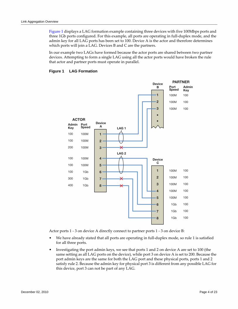
Link Aggregation Overview
Figure 1 displays a LAG formation example containing three devices with five 100Mbps ports and three 1Gb ports configured. For this example, all ports are operating in full‐duplex mode, and the admin key for all LAG ports has been set to 100. Device A is the actor and therefore determines which ports will join a LAG. Devices B and C are the partners.
In our example two LAGs have formed because the actor ports are shared between two partner devices. Attempting to form a single LAG using all the actor ports would have broken the rule that actor and partner ports must operate in parallel.
Figure 1 LAG Formation
Actor ports 1 ‐ 3 on device A directly connect to partner ports 1 ‐ 3 on device B:
• We have already stated that all ports are operating in full‐duplex mode, so rule 1 is satisfied for all three ports.
• Investigating the port admin keys, we see that ports 1 and 2 on device A are set to 100 (the same setting as all LAG ports on the device), while port 3 on device A is set to 200. Because the port admin keys are the same for both the LAG port and these physical ports, ports 1 and 2 satisfy rule 2. Because the admin key for physical port 3 is different from any possible LAG for this device, port 3 can not be part of any LAG.
PARTNERPortSpeed
DeviceB
DeviceA
DeviceC
LAG 1
LAG 2
AdminKey
ACTORPortSpeed
AdminKey
100
100
100
100
100
100
100
100
100
100
100
100M
100M
100M
100M
100M
1Gb
1Gb
1Gb
100
100
200
100
100
100
300
400
100M
100M
100M
100M
100M
1Gb
1Gb
1Gb
100M
100M
100M
1
2
3
4
5
6
7
8
1
2
3
4
5
6
7
8
1
2
3
December 02, 2010 Page 4 of 23
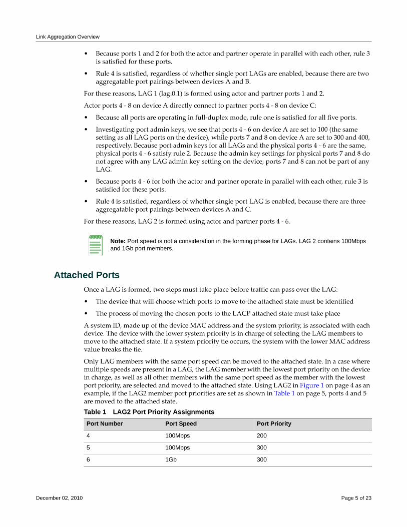
Link Aggregation Overview
• Because ports 1 and 2 for both the actor and partner operate in parallel with each other, rule 3 is satisfied for these ports.
• Rule 4 is satisfied, regardless of whether single port LAGs are enabled, because there are two aggregatable port pairings between devices A and B.
For these reasons, LAG 1 (lag.0.1) is formed using actor and partner ports 1 and 2.
Actor ports 4 ‐ 8 on device A directly connect to partner ports 4 ‐ 8 on device C:
• Because all ports are operating in full‐duplex mode, rule one is satisfied for all five ports.
• Investigating port admin keys, we see that ports 4 ‐ 6 on device A are set to 100 (the same setting as all LAG ports on the device), while ports 7 and 8 on device A are set to 300 and 400, respectively. Because port admin keys for all LAGs and the physical ports 4 ‐ 6 are the same, physical ports 4 ‐ 6 satisfy rule 2. Because the admin key settings for physical ports 7 and 8 do not agree with any LAG admin key setting on the device, ports 7 and 8 can not be part of any LAG.
• Because ports 4 ‐ 6 for both the actor and partner operate in parallel with each other, rule 3 is satisfied for these ports.
• Rule 4 is satisfied, regardless of whether single port LAG is enabled, because there are three aggregatable port pairings between devices A and C.
For these reasons, LAG 2 is formed using actor and partner ports 4 ‐ 6.
Attached PortsOnce a LAG is formed, two steps must take place before traffic can pass over the LAG:
• The device that will choose which ports to move to the attached state must be identified
• The process of moving the chosen ports to the LACP attached state must take place
A system ID, made up of the device MAC address and the system priority, is associated with each device. The device with the lower system priority is in charge of selecting the LAG members to move to the attached state. If a system priority tie occurs, the system with the lower MAC address value breaks the tie.
Only LAG members with the same port speed can be moved to the attached state. In a case where multiple speeds are present in a LAG, the LAG member with the lowest port priority on the device in charge, as well as all other members with the same port speed as the member with the lowest port priority, are selected and moved to the attached state. Using LAG2 in Figure 1 on page 4 as an example, if the LAG2 member port priorities are set as shown in Table 1 on page 5, ports 4 and 5 are moved to the attached state.
Note: Port speed is not a consideration in the forming phase for LAGs. LAG 2 contains 100Mbps and 1Gb port members.
Table 1 LAG2 Port Priority AssignmentsPort Number Port Speed Port Priority
4 100Mbps 200
5 100Mbps 300
6 1Gb 300
December 02, 2010 Page 5 of 23
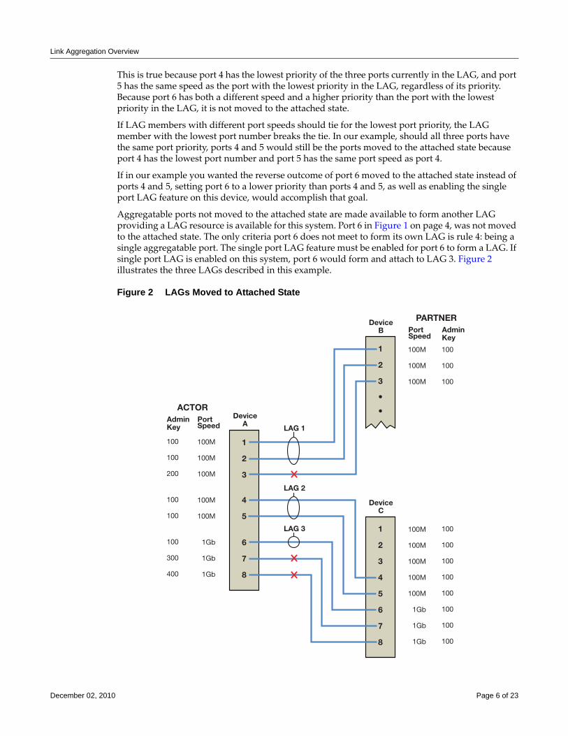
Link Aggregation Overview
This is true because port 4 has the lowest priority of the three ports currently in the LAG, and port 5 has the same speed as the port with the lowest priority in the LAG, regardless of its priority. Because port 6 has both a different speed and a higher priority than the port with the lowest priority in the LAG, it is not moved to the attached state.
If LAG members with different port speeds should tie for the lowest port priority, the LAG member with the lowest port number breaks the tie. In our example, should all three ports have the same port priority, ports 4 and 5 would still be the ports moved to the attached state because port 4 has the lowest port number and port 5 has the same port speed as port 4.
If in our example you wanted the reverse outcome of port 6 moved to the attached state instead of ports 4 and 5, setting port 6 to a lower priority than ports 4 and 5, as well as enabling the single port LAG feature on this device, would accomplish that goal.
Aggregatable ports not moved to the attached state are made available to form another LAG providing a LAG resource is available for this system. Port 6 in Figure 1 on page 4, was not moved to the attached state. The only criteria port 6 does not meet to form its own LAG is rule 4: being a single aggregatable port. The single port LAG feature must be enabled for port 6 to form a LAG. If single port LAG is enabled on this system, port 6 would form and attach to LAG 3. Figure 2 illustrates the three LAGs described in this example.
Figure 2 LAGs Moved to Attached State
PARTNERPortSpeed
DeviceB
DeviceA
DeviceC
LAG 1
LAG 2
LAG 3
AdminKey
ACTORPortSpeed
AdminKey
100
100
100
100
100
100
100
100
100
100
100
100M
100M
100M
100M
100M
1Gb
1Gb
1Gb
100
100
200
100
100
100
300
400
100M
100M
100M
100M
100M
1Gb
1Gb
1Gb
100M
100M
100M
1
2
3
4
5
6
7
8
1
2
3
4
5
6
7
8
1
2
3
December 02, 2010 Page 6 of 23
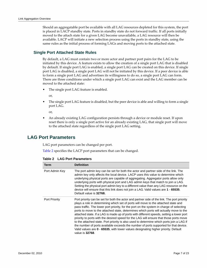
Link Aggregation Overview
Should an aggregatable port be available with all LAG resources depleted for this system, the port is placed in LACP standby state. Ports in standby state do not forward traffic. If all ports initially moved to the attach state for a given LAG become unavailable, a LAG resource will then be available. LACP will initiate a new selection process using the ports in standby state, using the same rules as the initial process of forming LAGs and moving ports to the attached state.
Single Port Attached State RulesBy default, a LAG must contain two or more actor and partner port pairs for the LAG to be initiated by this device. A feature exists to allow the creation of a single port LAG that is disabled by default. If single port LAG is enabled, a single port LAG can be created on this device. If single port LAG is disabled, a single port LAG will not be initiated by this device. If a peer device is able to form a single port LAG and advertises its willingness to do so, a single port LAG can form. There are three conditions under which a single port LAG can exist and the LAG member can be moved to the attached state:
• The single port LAG feature is enabled.
or,
• The single port LAG feature is disabled, but the peer device is able and willing to form a single port LAG.
or,
• An already existing LAG configuration persists through a device or module reset. If upon reset there is only a single port active for an already existing LAG, that single port will move to the attached state regardless of the single port LAG setting.
LAG Port ParametersLAG port parameters can be changed per port.
Table 2 specifies the LACP port parameters that can be changed.
Table 2 LAG Port ParametersTerm Definition
Port Admin Key The port admin key can be set for both the actor and partner side of the link. The admin key only affects the local device. LACP uses this value to determine which underlying physical ports are capable of aggregating. Aggregator ports allow only underlying ports with physical port and LAG admin keys that match to join a LAG. Setting the physical port admin key to a different value than any LAG resource on the device will ensure that this link does not join a LAG. Valid values are 1 - 65535. Default value is 32768.
Port Priority Port priority can be set for both the actor and partner side of the link. The port priority plays a role in determining which set of ports will move to the attached state and pass traffic. The lower port priority, for the port on the system in charge of selecting ports to move to the attached state, determines which ports will actually move to the attached state. If a LAG is made up of ports with different speeds, setting a lower port priority to ports with the desired speed for the LAG will ensure that those ports move to the attached state. Port priority is also used to determine which ports join a LAG if the number of ports available exceeds the number of ports supported for that device. Valid values are 0 - 65535, with lower values designating higher priority. Default value is 32768.
December 02, 2010 Page 7 of 23
Link Aggregation Overview
Flow Regeneration
Flow regeneration determines how flows will behave when a new port joins a link aggregation. When enabled, LACP will redistribute all existing flows over the LAG, taking into account the new port(s) that joined the LAG. It will also attempt to load balance existing flows to take advantage of the new port that has joined the LAG. When flow regeneration is disabled and a new port joins the LAG, the distribution of current flows remains unchanged and does not take advantage of the new port. All new flows will take into account the new port on the LAG. Flow regeneration is disabled by default.
The Out-Port Algorithm
The out‐port algorithm determines the criteria to be used for data forwarding port selection. There are three algorithm criteria to choose from:
Administrative State A number of port level administrative states can be set for both the actor and partner ports. The following port administrative states are set by default:
• lacpactive - Transmitting LACP PDUs is enabled.
• lacptimeout - Transmitting LACP PDUs every 30 seconds. If this state is disabled, LACP PDUs are transmitted every 1 second. Note that the actor and partner LACP timeout values must agree.
• lacpagg - Aggregation on this port is enabled.
• lacpsync - Transition to synchronization state is allowed.
• lacpcollect - Transition to collection state is allowed.
• lacpdist - Transition to distribution state is allowed.
• lacpdef - Transition to defaulted state is allowed.
• lacpexpire - Transition to expired state is allowed.
It is recommended that these default states not be changed unless you know what you are doing. Contact Enterasys customer support should you need assistance modifying port level administrative states.
Partner Default System ID
A default partner system ID can be set. This is a default MAC address for the system partner.
LACP PDU processing
(Optional) LACP PDU processing can be enabled or disabled for this port.
Table 2 LAG Port Parameters (continued)Term Definition
Note: The flow regeneration feature is supported on the N-Series and S-Series platforms only.
Note: The out-port algorithm feature is supported on the N-Series and S-Series platforms only.
December 02, 2010 Page 8 of 23
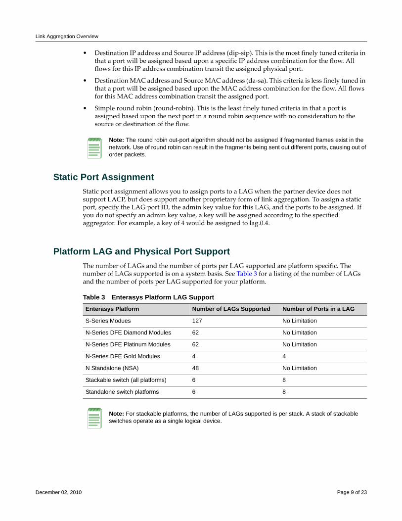
Link Aggregation Overview
• Destination IP address and Source IP address (dip‐sip). This is the most finely tuned criteria in that a port will be assigned based upon a specific IP address combination for the flow. All flows for this IP address combination transit the assigned physical port.
• Destination MAC address and Source MAC address (da‐sa). This criteria is less finely tuned in that a port will be assigned based upon the MAC address combination for the flow. All flows for this MAC address combination transit the assigned port.
• Simple round robin (round‐robin). This is the least finely tuned criteria in that a port is assigned based upon the next port in a round robin sequence with no consideration to the source or destination of the flow.
Static Port AssignmentStatic port assignment allows you to assign ports to a LAG when the partner device does not support LACP, but does support another proprietary form of link aggregation. To assign a static port, specify the LAG port ID, the admin key value for this LAG, and the ports to be assigned. If you do not specify an admin key value, a key will be assigned according to the specified aggregator. For example, a key of 4 would be assigned to lag.0.4.
Platform LAG and Physical Port SupportThe number of LAGs and the number of ports per LAG supported are platform specific. The number of LAGs supported is on a system basis. See Table 3 for a listing of the number of LAGs and the number of ports per LAG supported for your platform.
Note: The round robin out-port algorithm should not be assigned if fragmented frames exist in the network. Use of round robin can result in the fragments being sent out different ports, causing out of order packets.
Table 3 Enterasys Platform LAG SupportEnterasys Platform Number of LAGs Supported Number of Ports in a LAG
S-Series Modues 127 No Limitation
N-Series DFE Diamond Modules 62 No Limitation
N-Series DFE Platinum Modules 62 No Limitation
N-Series DFE Gold Modules 4 4
N Standalone (NSA) 48 No Limitation
Stackable switch (all platforms) 6 8
Standalone switch platforms 6 8
Note: For stackable platforms, the number of LAGs supported is per stack. A stack of stackable switches operate as a single logical device.
December 02, 2010 Page 9 of 23
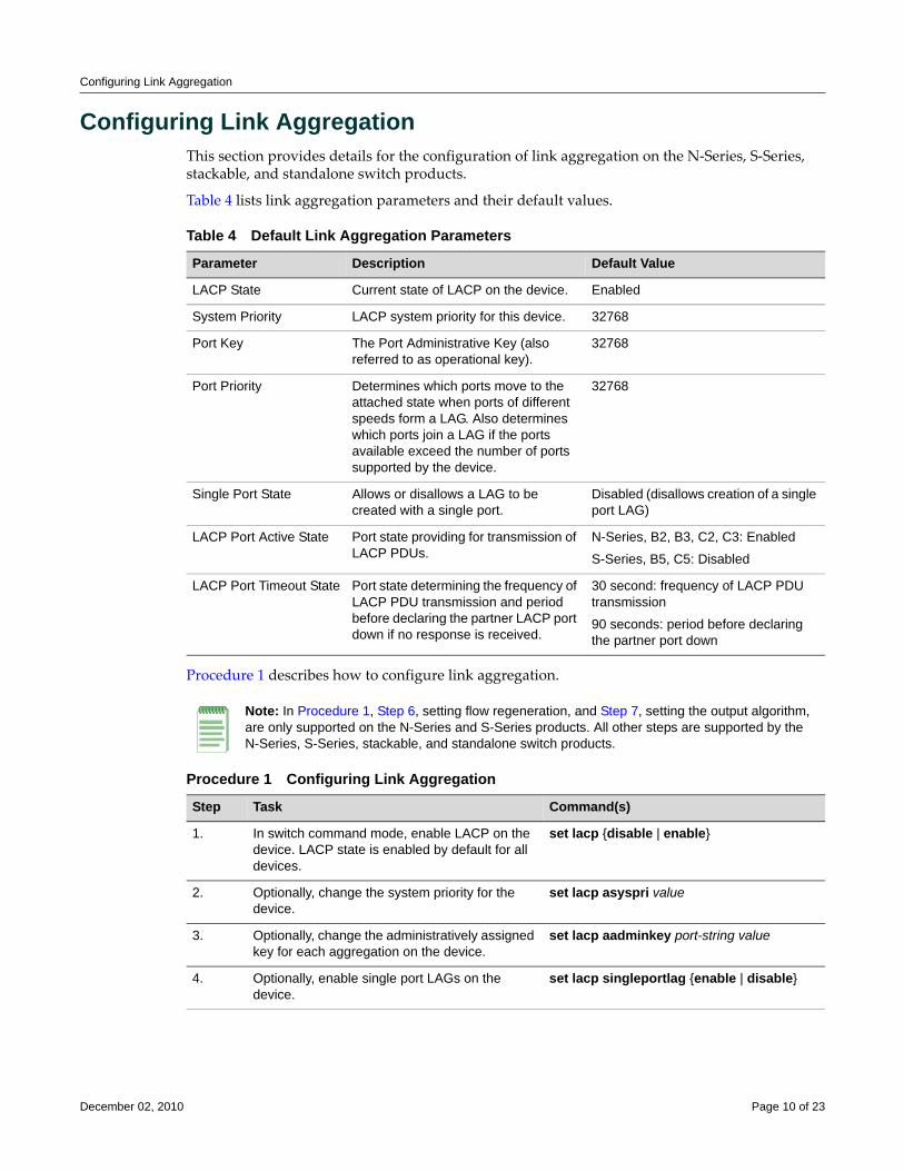
Configuring Link Aggregation
Configuring Link AggregationThis section provides details for the configuration of link aggregation on the N‐Series, S‐Series, stackable, and standalone switch products.
Table 4 lists link aggregation parameters and their default values.
Procedure 1 describes how to configure link aggregation.
Table 4 Default Link Aggregation Parameters
Parameter Description Default Value
LACP State Current state of LACP on the device. Enabled
System Priority LACP system priority for this device. 32768
Port Key The Port Administrative Key (also referred to as operational key).
32768
Port Priority Determines which ports move to the attached state when ports of different speeds form a LAG. Also determines which ports join a LAG if the ports available exceed the number of ports supported by the device.
32768
Single Port State Allows or disallows a LAG to be created with a single port.
Disabled (disallows creation of a single port LAG)
LACP Port Active State Port state providing for transmission of LACP PDUs.
N-Series, B2, B3, C2, C3: Enabled
S-Series, B5, C5: Disabled
LACP Port Timeout State Port state determining the frequency of LACP PDU transmission and period before declaring the partner LACP port down if no response is received.
30 second: frequency of LACP PDU transmission
90 seconds: period before declaring the partner port down
Note: In Procedure 1, Step 6, setting flow regeneration, and Step 7, setting the output algorithm, are only supported on the N-Series and S-Series products. All other steps are supported by the N-Series, S-Series, stackable, and standalone switch products.
Procedure 1 Configuring Link Aggregation
Step Task Command(s)
1. In switch command mode, enable LACP on the device. LACP state is enabled by default for all devices.
set lacp {disable | enable}
2. Optionally, change the system priority for the device.
set lacp asyspri value
3. Optionally, change the administratively assigned key for each aggregation on the device.
set lacp aadminkey port-string value
4. Optionally, enable single port LAGs on the device.
set lacp singleportlag {enable | disable}
December 02, 2010 Page 10 of 23
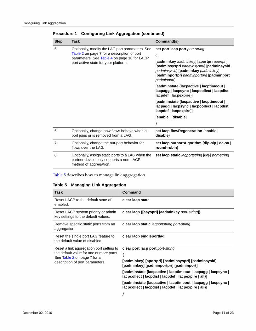
Configuring Link Aggregation
Table 5 describes how to manage link aggregation.
5. Optionally, modify the LAG port parameters. See Table 2 on page 7 for a description of port parameters. See Table 4 on page 10 for LACP port active state for your platform.
set port lacp port port-string
{
[aadminkey aadminkey] [aportpri aportpri] [padminsyspri padminsyspri] [padminsysid padminsysid] [padminkey padminkey] [padminportpri padminportpri] [padminport padminport]
[aadminstate {lacpactive | lacptimeout | lacpagg | lacpsync | lacpcollect | lacpdist | lacpdef | lacpexpire}]
[padminstate {lacpactive | lacptimeout | lacpagg | lacpsync | lacpcollect | lacpdist | lacpdef | lacpexpire}]
[enable | [disable]
}
6. Optionally, change how flows behave when a port joins or is removed from a LAG.
set lacp flowRegeneration {enable | disable}
7. Optionally, change the out-port behavior for flows over the LAG.
set lacp outportAlgorithm {dip-sip | da-sa | round-robin}
8. Optionally, assign static ports to a LAG when the partner device only supports a non-LACP method of aggregation.
set lacp static lagportstring [key] port-string
Table 5 Managing Link AggregationTask Command
Reset LACP to the default state of enabled.
clear lacp state
Reset LACP system priority or admin key settings to the default values.
clear lacp {[asyspri] [aadminkey port-string]}
Remove specific static ports from an aggregation.
clear lacp static lagportstring port-string
Reset the single port LAG feature to the default value of disabled.
clear lacp singleportlag
Reset a link aggregation port setting to the default value for one or more ports. See Table 2 on page 7 for a description of port parameters.
clear port lacp port port-string {[aadminkey] [aportpri] [padminsyspri] [padminsysid] [padminkey] [padminportpri] [padminport][aadminstate {lacpactive | lacptimeout | lacpagg | lacpsync | lacpcollect | lacpdist | lacpdef | lacpexpire | all}][padminstate {lacpactive | lacptimeout | lacpagg | lacpsync | lacpcollect | lacpdist | lacpdef | lacpexpire | all}]}
Procedure 1 Configuring Link Aggregation (continued)
Step Task Command(s)
December 02, 2010 Page 11 of 23
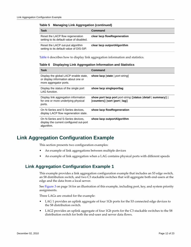
Link Aggregation Configuration Example
Table 6 describes how to display link aggregation information and statistics.
Link Aggregation Configuration ExampleThis section presents two configuration examples:
• An example of link aggregations between multiple devices
• An example of link aggregation when a LAG contains physical ports with different speeds
Link Aggregation Configuration Example 1This example provides a link aggregation configuration example that includes an S3 edge switch, an S8 distribution switch, and two C3 stackable switches that will aggregate both end‐users at the edge and the data from a local server.
See Figure 3 on page 14 for an illustration of this example, including port, key, and system priority assignments.
Three LAGs are created for the example:
• LAG 1 provides an uplink aggregate of four 1Gb ports for the S3 connected edge devices to the S8 distribution switch.
• LAG2 provides an uplink aggregate of four 1Gb ports for the C3 stackable switches to the S8 distribution switch for both the end‐user and server data flows.
Reset the LACP flow regeneration setting to its default value of disabled.
clear lacp flowRegeneration
Reset the LACP out-put algorithm setting to its default value of DIS-SIP.
clear lacp outportAlgorithm
Table 6 Displaying Link Aggregation Information and StatisticsTask Command
Display the global LACP enable state, or display information about one or more aggregator ports.
show lacp [state | port-string]
Display the status of the single port LAG function.
show lacp singleportlag
Display link aggregation information for one or more underlying physical ports.
show port lacp port port-string {[status {detail | summary}] | [counters]} [sort {port | lag}]
On N-Series and S-Series devices, display LACP flow regeneration state.
show lacp flowRegeneration
On N-Series and S-Series devices, display the current configured out-port algorithm.
show lacp outportAlgorithm
Table 5 Managing Link Aggregation (continued)Task Command
December 02, 2010 Page 12 of 23

Link Aggregation Configuration Example
• LAG3 provides an aggregate of four 1Gb ports between the C3 stackable switches and the server.
Each LAG consists of four ports. The primary goal of the aggregates in this example is to provide link and slot redundancy for the affected data streams. With that in mind, LAG members are spread between available system slots. Four out of the five S8 available slots are used providing complete redundancy at the S8. All three slots are used in the S3. The four ports from the server to the C3 stackable switches and the C3 stackable switches to the S8 are evenly split between the two stackable switches.
For this example we will manually configure the LAGs that will form and prevent any other LAGs from forming. Because we have specific port to LAG goals in mind, the first thing we want to do on each device is to ensure that LAGs form only where we configure them. Since the admin key for the LAG and its associated ports must agree for the LAG to form, an easy way to ensure that LAGs do not automatically form is to set the admin key for all LAGS on all devices to a non‐default value. The physical ports will initially retain admin key defaults. In our example, the admin keys for all LAGs are set to the highest configurable value of 65535.
December 02, 2010 Page 13 of 23
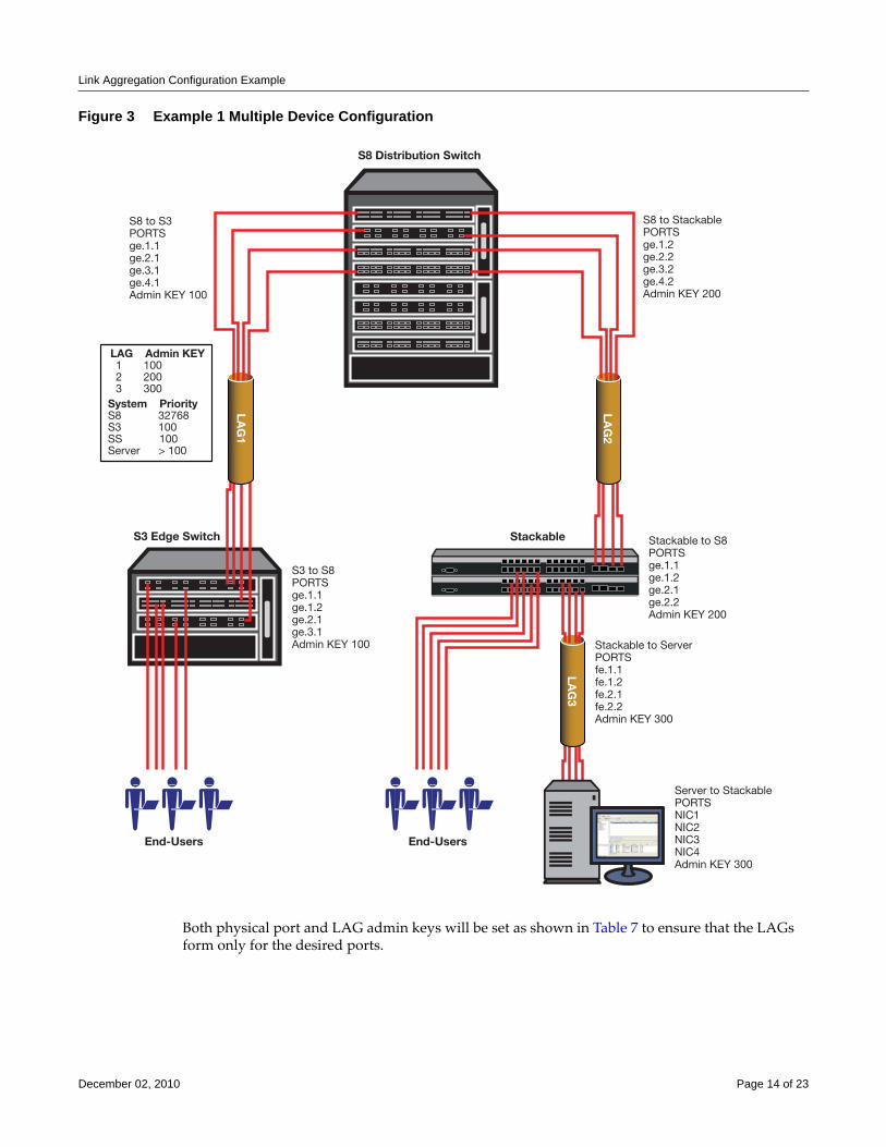
Link Aggregation Configuration Example
Figure 3 Example 1 Multiple Device Configuration
Both physical port and LAG admin keys will be set as shown in Table 7 to ensure that the LAGs form only for the desired ports.
S3 Edge Switch Stackable to S8PORTSge.1.1ge.1.2ge.2.1ge.2.2Admin KEY 200
S8 Distribution Switch
LAG
1
End-Users
Stackable
LAG
2
LAG Admin KEY1 1002 2003 300
System PriorityS8 32768S3 100SS 100Server > 100
LAG
3
Server to StackablePORTSNIC1NIC2NIC3NIC4Admin KEY 300
Stackable to ServerPORTSfe.1.1fe.1.2fe.2.1fe.2.2Admin KEY 300
S3 to S8PORTSge.1.1ge.1.2ge.2.1ge.3.1Admin KEY 100
End-Users
S8 to StackablePORTSge.1.2ge.2.2ge.3.2ge.4.2Admin KEY 200
S8 to S3PORTSge.1.1ge.2.1ge.3.1ge.4.1Admin KEY 100
December 02, 2010 Page 14 of 23
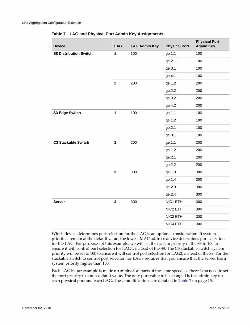
Link Aggregation Configuration Example
Which device determines port selection for the LAG is an optional consideration. If system priorities remain at the default value, the lowest MAC address device determines port selection for the LAG. For purposes of this example, we will set the system priority of the S3 to 100 to ensure it will control port selection for LAG1, instead of the S8. The C3 stackable switch system priority will be set to 100 to ensure it will control port selection for LAG2, instead of the S8. For the stackable switch to control port selection for LAG3 requires that you ensure that the server has a system priority higher than 100.
Each LAG in our example is made up of physical ports of the same speed, so there is no need to set the port priority to a non‐default value. The only port value to be changed is the admin key for each physical port and each LAG. These modifications are detailed in Table 7 on page 15.
Table 7 LAG and Physical Port Admin Key Assignments
Device LAG LAG Admin Key Physical Port Physical Port Admin Key
S8 Distribution Switch 1 100 ge.1.1 100
ge.2.1 100
ge.3.1 100
ge.4.1 100
2 200 ge.1.2 200
ge.2.2 200
ge.3.2 200
ge.4.2 200
S3 Edge Switch 1 100 ge.1.1 100
ge.1.2 100
ge.2.1 100
ge.3.1 100
C3 Stackable Switch 2 200 ge.1.1 200
ge.1.2 200
ge.2.1 200
ge.2.2 200
3 300 ge.1.3 300
ge.1.4 300
ge.2.3 300
ge.2.4 300
Server 3 300 NIC1 ETH 300
NIC2 ETH 300
NIC3 ETH 300
NIC4 ETH 300
December 02, 2010 Page 15 of 23
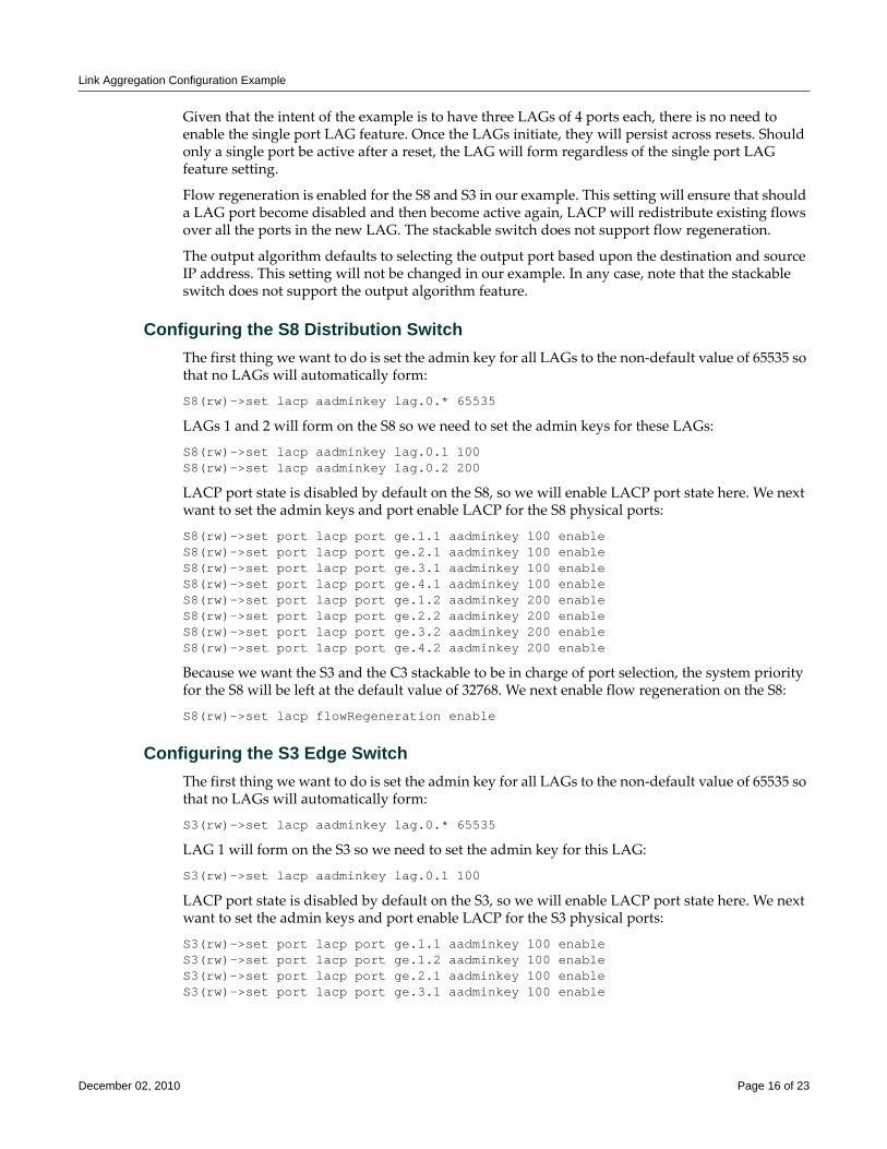
Link Aggregation Configuration Example
Given that the intent of the example is to have three LAGs of 4 ports each, there is no need to enable the single port LAG feature. Once the LAGs initiate, they will persist across resets. Should only a single port be active after a reset, the LAG will form regardless of the single port LAG feature setting.
Flow regeneration is enabled for the S8 and S3 in our example. This setting will ensure that should a LAG port become disabled and then become active again, LACP will redistribute existing flows over all the ports in the new LAG. The stackable switch does not support flow regeneration.
The output algorithm defaults to selecting the output port based upon the destination and source IP address. This setting will not be changed in our example. In any case, note that the stackable switch does not support the output algorithm feature.
Configuring the S8 Distribution SwitchThe first thing we want to do is set the admin key for all LAGs to the non‐default value of 65535 so that no LAGs will automatically form:
S8(rw)->set lacp aadminkey lag.0.* 65535
LAGs 1 and 2 will form on the S8 so we need to set the admin keys for these LAGs:
S8(rw)->set lacp aadminkey lag.0.1 100S8(rw)->set lacp aadminkey lag.0.2 200
LACP port state is disabled by default on the S8, so we will enable LACP port state here. We next want to set the admin keys and port enable LACP for the S8 physical ports:
S8(rw)->set port lacp port ge.1.1 aadminkey 100 enableS8(rw)->set port lacp port ge.2.1 aadminkey 100 enableS8(rw)->set port lacp port ge.3.1 aadminkey 100 enableS8(rw)->set port lacp port ge.4.1 aadminkey 100 enableS8(rw)->set port lacp port ge.1.2 aadminkey 200 enableS8(rw)->set port lacp port ge.2.2 aadminkey 200 enableS8(rw)->set port lacp port ge.3.2 aadminkey 200 enableS8(rw)->set port lacp port ge.4.2 aadminkey 200 enable
Because we want the S3 and the C3 stackable to be in charge of port selection, the system priority for the S8 will be left at the default value of 32768. We next enable flow regeneration on the S8:
S8(rw)->set lacp flowRegeneration enable
Configuring the S3 Edge SwitchThe first thing we want to do is set the admin key for all LAGs to the non‐default value of 65535 so that no LAGs will automatically form:
S3(rw)->set lacp aadminkey lag.0.* 65535
LAG 1 will form on the S3 so we need to set the admin key for this LAG:
S3(rw)->set lacp aadminkey lag.0.1 100
LACP port state is disabled by default on the S3, so we will enable LACP port state here. We next want to set the admin keys and port enable LACP for the S3 physical ports:
S3(rw)->set port lacp port ge.1.1 aadminkey 100 enableS3(rw)->set port lacp port ge.1.2 aadminkey 100 enableS3(rw)->set port lacp port ge.2.1 aadminkey 100 enableS3(rw)->set port lacp port ge.3.1 aadminkey 100 enable
December 02, 2010 Page 16 of 23
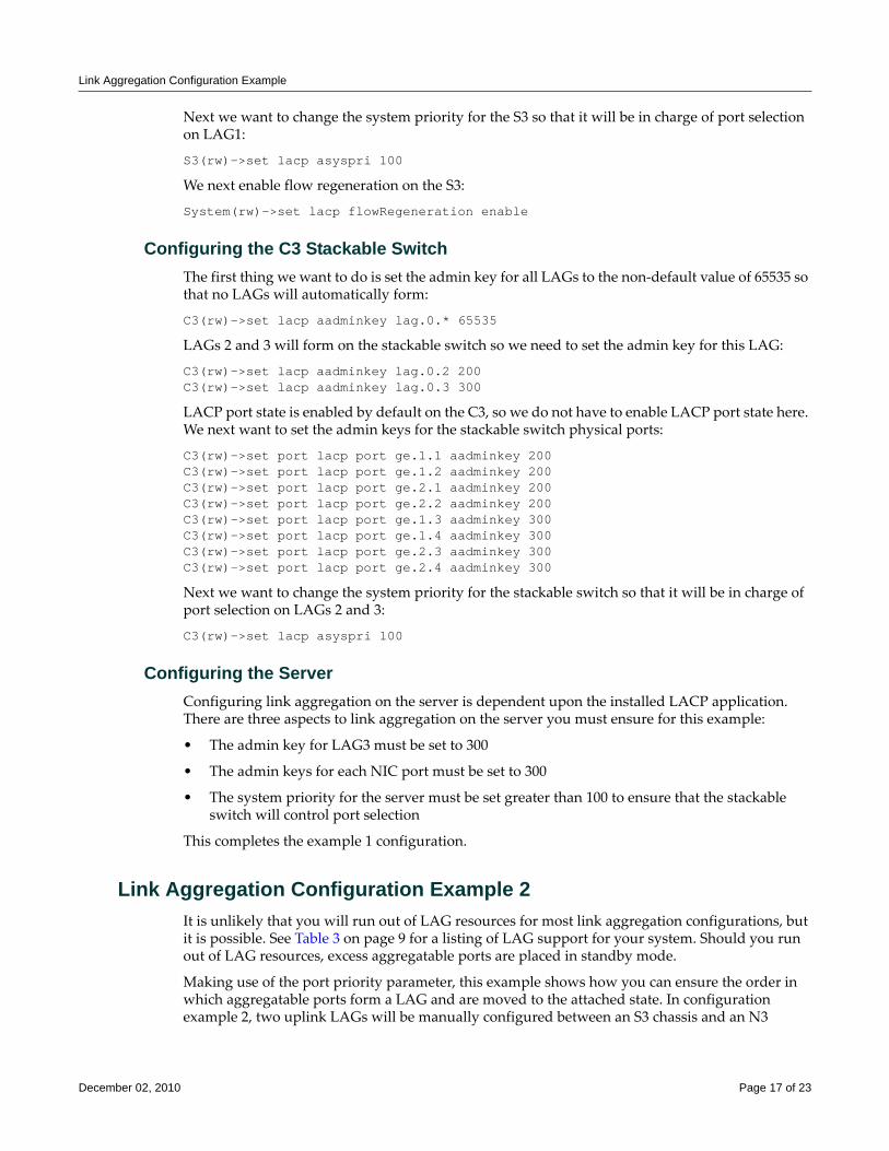
Link Aggregation Configuration Example
Next we want to change the system priority for the S3 so that it will be in charge of port selection on LAG1:
S3(rw)->set lacp asyspri 100
We next enable flow regeneration on the S3:
System(rw)->set lacp flowRegeneration enable
Configuring the C3 Stackable SwitchThe first thing we want to do is set the admin key for all LAGs to the non‐default value of 65535 so that no LAGs will automatically form:
C3(rw)->set lacp aadminkey lag.0.* 65535
LAGs 2 and 3 will form on the stackable switch so we need to set the admin key for this LAG:
C3(rw)->set lacp aadminkey lag.0.2 200C3(rw)->set lacp aadminkey lag.0.3 300
LACP port state is enabled by default on the C3, so we do not have to enable LACP port state here. We next want to set the admin keys for the stackable switch physical ports:
C3(rw)->set port lacp port ge.1.1 aadminkey 200 C3(rw)->set port lacp port ge.1.2 aadminkey 200 C3(rw)->set port lacp port ge.2.1 aadminkey 200 C3(rw)->set port lacp port ge.2.2 aadminkey 200 C3(rw)->set port lacp port ge.1.3 aadminkey 300 C3(rw)->set port lacp port ge.1.4 aadminkey 300 C3(rw)->set port lacp port ge.2.3 aadminkey 300 C3(rw)->set port lacp port ge.2.4 aadminkey 300
Next we want to change the system priority for the stackable switch so that it will be in charge of port selection on LAGs 2 and 3:
C3(rw)->set lacp asyspri 100
Configuring the ServerConfiguring link aggregation on the server is dependent upon the installed LACP application. There are three aspects to link aggregation on the server you must ensure for this example:
• The admin key for LAG3 must be set to 300
• The admin keys for each NIC port must be set to 300
• The system priority for the server must be set greater than 100 to ensure that the stackable switch will control port selection
This completes the example 1 configuration.
Link Aggregation Configuration Example 2It is unlikely that you will run out of LAG resources for most link aggregation configurations, but it is possible. See Table 3 on page 9 for a listing of LAG support for your system. Should you run out of LAG resources, excess aggregatable ports are placed in standby mode.
Making use of the port priority parameter, this example shows how you can ensure the order in which aggregatable ports form a LAG and are moved to the attached state. In configuration example 2, two uplink LAGs will be manually configured between an S3 chassis and an N3
December 02, 2010 Page 17 of 23
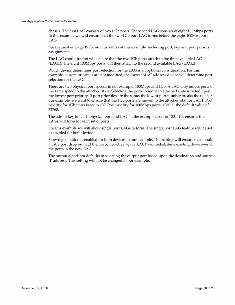
Link Aggregation Configuration Example
chassis. The first LAG consists of two 1 Gb ports. The second LAG consists of eight 100Mbps ports. In this example we will ensure that the two 1Gb port LAG forms before the eight 100Mbs port LAG.
See Figure 4 on page 19 for an illustration of this example, including port, key and port priority assignments.
The LAG configuration will ensure that the two 1Gb ports attach to the first available LAG (LAG1). The eight 100Mbps ports will then attach to the second available LAG (LAG2)
Which device determines port selection for the LAG is an optional consideration. For this example, system priorities are not modified, the lowest MAC address device will determine port selection for the LAG.
There are two physical port speeds in our example, 100Mbps and 1Gb. A LAG only moves ports of the same speed to the attached state. Selecting the ports to move to attached state is based upon the lowest port priority. If port priorities are the same, the lowest port number breaks the tie. For our example, we want to ensure that the 1Gb ports are moved to the attached stat for LAG1. Port priority for 1Gb ports is set to 100. Port priority for 100Mbps ports is left at the default value of 32768.
The admin key for each physical port and LAG in the example is set to 100. This ensures that LAGs will form for each set of ports.
For this example we will allow single port LAGs to form. The single port LAG feature will be set to enabled for both devices.
Flow regeneration is enabled for both devices in our example. This setting will ensure that should a LAG port drop out and then become active again, LACP will redistribute existing flows over all the ports in the new LAG.
The output algorithm defaults to selecting the output port based upon the destination and source IP address. This setting will not be changed in our example.
December 02, 2010 Page 18 of 23
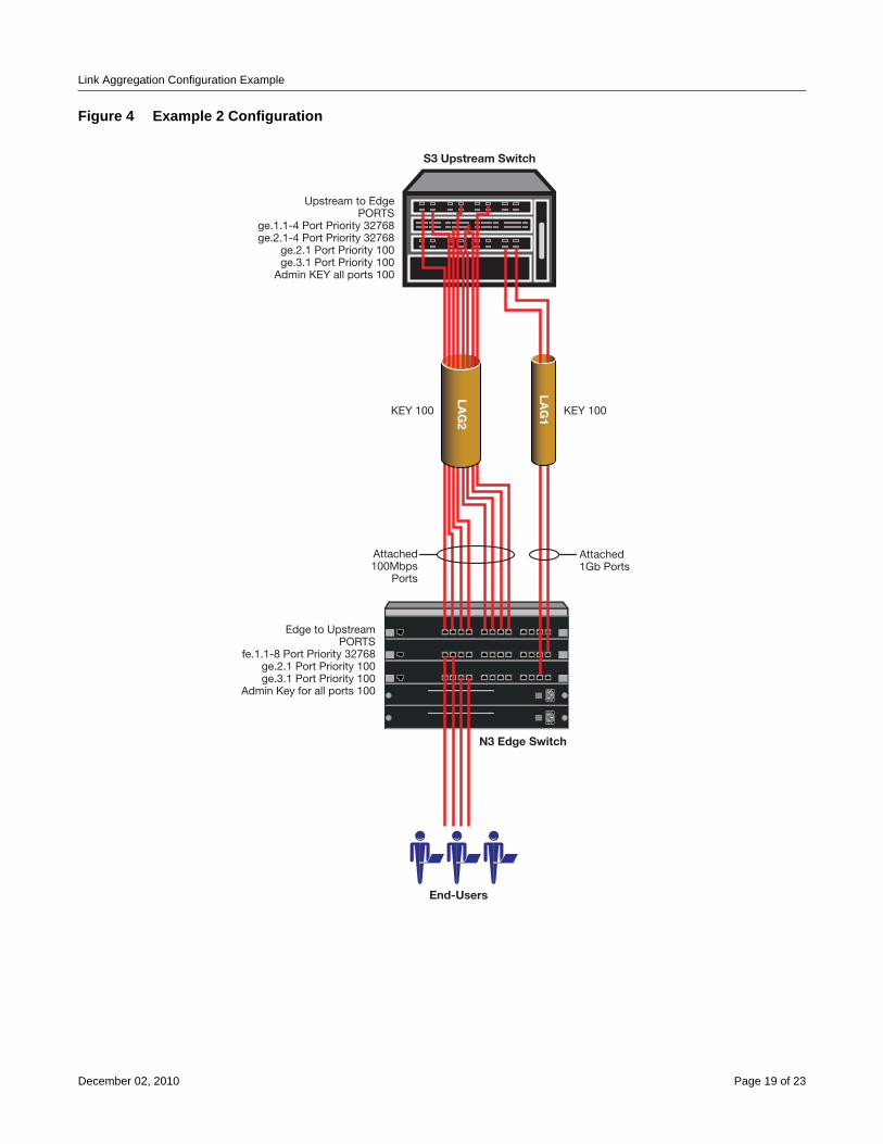
Link Aggregation Configuration Example
Figure 4 Example 2 Configuration
N3 Edge Switch
S3 Upstream Switch
LAG
1
End-Users
KEY 100KEY 100
Edge to UpstreamPORTS
fe.1.1-8 Port Priority 32768ge.2.1 Port Priority 100ge.3.1 Port Priority 100
Admin Key for all ports 100
LAG
2
Attached100Mbps
Ports
Attached1Gb Ports
Upstream to EdgePORTS
ge.1.1-4 Port Priority 32768ge.2.1-4 Port Priority 32768
ge.2.1 Port Priority 100ge.3.1 Port Priority 100
Admin KEY all ports 100
December 02, 2010 Page 19 of 23
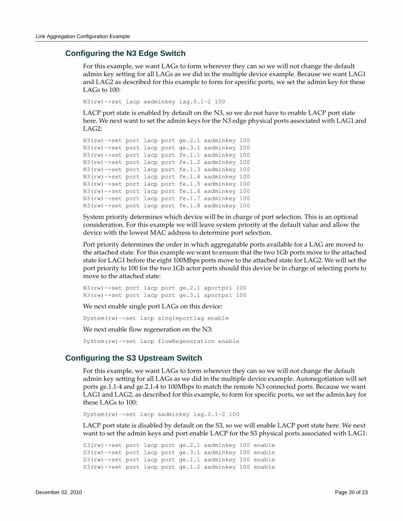
Link Aggregation Configuration Example
Configuring the N3 Edge SwitchFor this example, we want LAGs to form wherever they can so we will not change the default admin key setting for all LAGs as we did in the multiple device example. Because we want LAG1 and LAG2 as described for this example to form for specific ports, we set the admin key for these LAGs to 100:
N3(rw)->set lacp aadminkey lag.0.1-2 100
LACP port state is enabled by default on the N3, so we do not have to enable LACP port state here. We next want to set the admin keys for the N3 edge physical ports associated with LAG1 and LAG2:
N3(rw)->set port lacp port ge.2.1 aadminkey 100 N3(rw)->set port lacp port ge.3.1 aadminkey 100 N3(rw)->set port lacp port fe.1.1 aadminkey 100 N3(rw)->set port lacp port fe.1.2 aadminkey 100 N3(rw)->set port lacp port fe.1.3 aadminkey 100 N3(rw)->set port lacp port fe.1.4 aadminkey 100 N3(rw)->set port lacp port fe.1.5 aadminkey 100 N3(rw)->set port lacp port fe.1.6 aadminkey 100 N3(rw)->set port lacp port fe.1.7 aadminkey 100 N3(rw)->set port lacp port fe.1.8 aadminkey 100
System priority determines which device will be in charge of port selection. This is an optional consideration. For this example we will leave system priority at the default value and allow the device with the lowest MAC address to determine port selection.
Port priority determines the order in which aggregatable ports available for a LAG are moved to the attached state. For this example we want to ensure that the two 1Gb ports move to the attached state for LAG1 before the eight 100Mbps ports move to the attached state for LAG2. We will set the port priority to 100 for the two 1Gb actor ports should this device be in charge of selecting ports to move to the attached state:
N3(rw)->set port lacp port ge.2.1 aportpri 100N3(rw)->set port lacp port ge.3.1 aportpri 100
We next enable single port LAGs on this device:
System(rw)->set lacp singleportlag enable
We next enable flow regeneration on the N3:
System(rw)->set lacp flowRegeneration enable
Configuring the S3 Upstream SwitchFor this example, we want LAGs to form wherever they can so we will not change the default admin key setting for all LAGs as we did in the multiple device example. Autonegotiation will set ports ge.1.1‐4 and ge.2.1‐4 to 100Mbps to match the remote N3 connected ports. Because we want LAG1 and LAG2, as described for this example, to form for specific ports, we set the admin key for these LAGs to 100:
System(rw)->set lacp aadminkey lag.0.1-2 100
LACP port state is disabled by default on the S3, so we will enable LACP port state here. We next want to set the admin keys and port enable LACP for the S3 physical ports associated with LAG1:
S3(rw)->set port lacp port ge.2.1 aadminkey 100 enableS3(rw)->set port lacp port ge.3.1 aadminkey 100 enableS3(rw)->set port lacp port ge.1.1 aadminkey 100 enableS3(rw)->set port lacp port ge.1.2 aadminkey 100 enable
December 02, 2010 Page 20 of 23
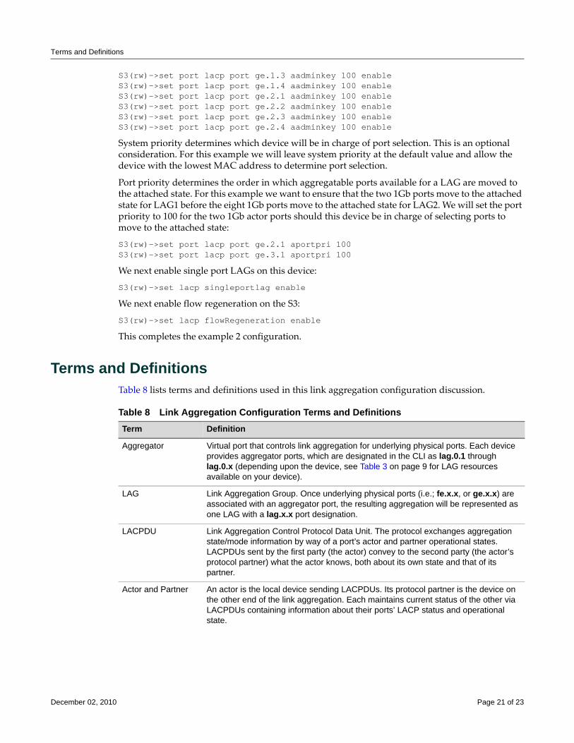
Terms and Definitions
S3(rw)->set port lacp port ge.1.3 aadminkey 100 enableS3(rw)->set port lacp port ge.1.4 aadminkey 100 enableS3(rw)->set port lacp port ge.2.1 aadminkey 100 enableS3(rw)->set port lacp port ge.2.2 aadminkey 100 enableS3(rw)->set port lacp port ge.2.3 aadminkey 100 enableS3(rw)->set port lacp port ge.2.4 aadminkey 100 enable
System priority determines which device will be in charge of port selection. This is an optional consideration. For this example we will leave system priority at the default value and allow the device with the lowest MAC address to determine port selection.
Port priority determines the order in which aggregatable ports available for a LAG are moved to the attached state. For this example we want to ensure that the two 1Gb ports move to the attached state for LAG1 before the eight 1Gb ports move to the attached state for LAG2. We will set the port priority to 100 for the two 1Gb actor ports should this device be in charge of selecting ports to move to the attached state:
S3(rw)->set port lacp port ge.2.1 aportpri 100S3(rw)->set port lacp port ge.3.1 aportpri 100
We next enable single port LAGs on this device:
S3(rw)->set lacp singleportlag enable
We next enable flow regeneration on the S3:
S3(rw)->set lacp flowRegeneration enable
This completes the example 2 configuration.
Terms and DefinitionsTable 8 lists terms and definitions used in this link aggregation configuration discussion.
Table 8 Link Aggregation Configuration Terms and Definitions Term Definition
Aggregator Virtual port that controls link aggregation for underlying physical ports. Each device provides aggregator ports, which are designated in the CLI as lag.0.1 through lag.0.x (depending upon the device, see Table 3 on page 9 for LAG resources available on your device).
LAG Link Aggregation Group. Once underlying physical ports (i.e.; fe.x.x, or ge.x.x) are associated with an aggregator port, the resulting aggregation will be represented as one LAG with a lag.x.x port designation.
LACPDU Link Aggregation Control Protocol Data Unit. The protocol exchanges aggregation state/mode information by way of a port’s actor and partner operational states. LACPDUs sent by the first party (the actor) convey to the second party (the actor’s protocol partner) what the actor knows, both about its own state and that of its partner.
Actor and Partner An actor is the local device sending LACPDUs. Its protocol partner is the device on the other end of the link aggregation. Each maintains current status of the other via LACPDUs containing information about their ports’ LACP status and operational state.
December 02, 2010 Page 21 of 23
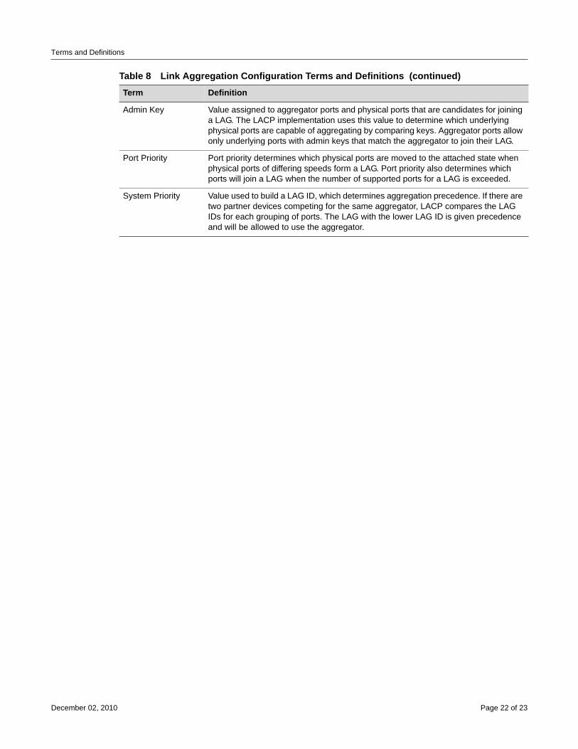
Terms and Definitions
Admin Key Value assigned to aggregator ports and physical ports that are candidates for joining a LAG. The LACP implementation uses this value to determine which underlying physical ports are capable of aggregating by comparing keys. Aggregator ports allow only underlying ports with admin keys that match the aggregator to join their LAG.
Port Priority Port priority determines which physical ports are moved to the attached state when physical ports of differing speeds form a LAG. Port priority also determines which ports will join a LAG when the number of supported ports for a LAG is exceeded.
System Priority Value used to build a LAG ID, which determines aggregation precedence. If there are two partner devices competing for the same aggregator, LACP compares the LAG IDs for each grouping of ports. The LAG with the lower LAG ID is given precedence and will be allowed to use the aggregator.
Table 8 Link Aggregation Configuration Terms and Definitions (continued)Term Definition
December 02, 2010 Page 22 of 23
Revision History
Enterasys Networks reserves the right to make changes in specifications and other information contained in this document and its web site without prior notice. The reader should in all cases consult Enterasys Networks to determine whether any such changes have been made.
The hardware, firmware, or software described in this document is subject to change without notice.
IN NO EVENT SHALL ENTERASYS NETWORKS BE LIABLE FOR ANY INCIDENTAL, INDIRECT, SPECIAL, OR CONSEQUENTIAL DAMAGES WHATSOEVER (INCLUDING BUT NOT LIMITED TO LOST PROFITS) ARISING OUT OF OR RELATED TO THIS DOCUMENT, WEB SITE, OR THE INFORMATION CONTAINED IN THEM, EVEN IF ENTERASYS NETWORKS HAS BEEN ADVISED OF, KNEW OF, OR SHOULD HAVE KNOWN OF, THE POSSIBILITY OF SUCH DAMAGES.
Enterasys Networks, Inc.50 Minuteman RoadAndover, MA 01810
© 2010 Enterasys Networks, Inc. All rights reserved.
ENTERASYS, ENTERASYS NETWORKS, ENTERASYS MATRIX, ENTERASYS, S‐SERIES and any logos associated therewith, are trademarks or registered trademarks of Enterasys Networks, Inc., in the United States and other countries.
For a complete list of Enterasys trademarks, see http://www.enterasys.com/company/trademarks.aspx.
All other product names mentioned in this manual may be trademarks or registered trademarks of their respective companies.
Date Description
December 05, 2008 New Document.
December 02, 2010 Update for S-Series, B5, and C5 platforms.
Configuring Link Flap Detection
This document provides information about configuring the link flap detection feature on Enterasys Matrix® N‐Series, Enterasys SecureStack™, D‐Series, G‐Series, and I‐Series devices.
What is Link Flap Detection?The link flap detection feature monitors link flapping (that is, when a link goes up and down rapidly) on a physical port. Link flapping indicates a Layer 1 (physical layer) problem, such as a faulty cable or GBIC. If link flapping occurs, your Enterasys device can react by disabling the affected port and generating a syslog entry and an SNMP trap to notify you of the event.
Why Would I Use Link Flap Detection in My Network?If left unresolved, link flapping can be detrimental to network stability by triggering Spanning Tree and routing table recalculations. By enabling the link flap detection feature on your Enterasys device, you can monitor and act upon link flapping to avoid these recalculations.
How Do I Implement Link Flap Detection?You can enable link flap detection globally on your Enterasys device or on specific ports, such as uplink ports. The link flap detection feature allows you to specify the action that occurs when a certain number of link flapping instances occur within a certain period of time. By default, if a port on which link flap is enabled experiences five link flapping instances within a 10‐second period, that port will be disabled for 300 seconds and both a syslog entry and an SNMP trap will be generated.
If a port has been disabled because of excessive link flapping, you can reset the port to operational.
Note: Link flap detection is not supported on Enterasys Matrix X-Series devices.
For information about... Refer to page...
What is Link Flap Detection? 1
Why Would I Use Link Flap Detection in My Network? 1
How Do I Implement Link Flap Detection? 1
Configuring Link Flap Detection 2
January 29, 2009 Page 1 of 4
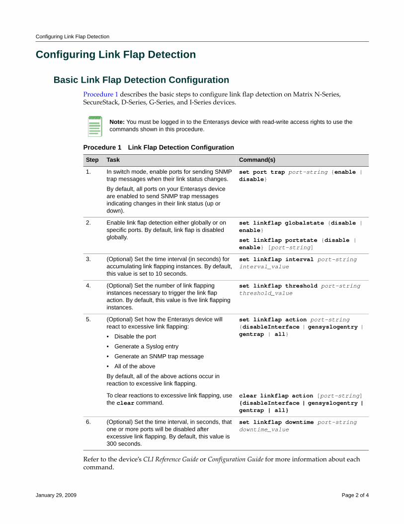
Configuring Link Flap Detection
Configuring Link Flap Detection
Basic Link Flap Detection ConfigurationProcedure 1 describes the basic steps to configure link flap detection on Matrix N‐Series, SecureStack, D‐Series, G‐Series, and I‐Series devices.
Refer to the device’s CLI Reference Guide or Configuration Guide for more information about each command.
Note: You must be logged in to the Enterasys device with read-write access rights to use the commands shown in this procedure.
Procedure 1 Link Flap Detection Configuration
Step Task Command(s)
1. In switch mode, enable ports for sending SNMP trap messages when their link status changes.
By default, all ports on your Enterasys device are enabled to send SNMP trap messages indicating changes in their link status (up or down).
set port trap port-string {enable | disable}
2. Enable link flap detection either globally or on specific ports. By default, link flap is disabled globally.
set linkflap globalstate {disable | enable}
set linkflap portstate {disable | enable} [port-string]
3. (Optional) Set the time interval (in seconds) for accumulating link flapping instances. By default, this value is set to 10 seconds.
set linkflap interval port-string interval_value
4. (Optional) Set the number of link flapping instances necessary to trigger the link flap action. By default, this value is five link flapping instances.
set linkflap threshold port-string threshold_value
5. (Optional) Set how the Enterasys device will react to excessive link flapping:
• Disable the port
• Generate a Syslog entry
• Generate an SNMP trap message
• All of the above
By default, all of the above actions occur in reaction to excessive link flapping.
set linkflap action port-string {disableInterface | gensyslogentry | gentrap | all}
To clear reactions to excessive link flapping, use the clear command.
clear linkflap action [port-string] {disableInterface | gensyslogentry | gentrap | all}
6. (Optional) Set the time interval, in seconds, that one or more ports will be disabled after excessive link flapping. By default, this value is 300 seconds.
set linkflap downtime port-string downtime_value
January 29, 2009 Page 2 of 4
Configuring Link Flap Detection
Example Link Flap Detection ConfigurationPoE devices (for example, VoIP phones or wireless access points) connected to a Matrix N device are experiencing intermittent power losses, though the Matrix N device itself has not experienced any corresponding power losses. The network administrator enables link flap detection on a range of PoE ports to which the PoE devices are connected.
Matrix(rw)->set linkflap portstate enable ge.1.1-12
The network administrator also sets values for the interval, threshold, and downtime on the ports.
Matrix(rw)->set linkflap interval ge.1.1-12 20
Matrix(rw)->set linkflap threshold ge.1.1-12 8
Matrix(rw)->set linkflap downtime ge.1.1-12 600
If the link flap threshold is exceeded within the link flap interval (eight link flap conditions within 20 seconds, as configured above), the Matrix N device will, by default, disable the port (for 600 seconds, as configured above) and generate both a syslog entry and an SNMP trap. These default actions can be changed by using the set linkflap action command.
The Matrix N device disables ports ge.1.1 and ge.1.2 when excessive link flapping occurs on the ports. The network administrator can check the status of the ports and the number of link flap conditions that occurred by using the show linkflap metrics command.
While the ports are disabled, the network administrator replaces the potentially faulty Ethernet cables connecting the ports to the PoE devices. The network administrator then enables the ports.
Matrix(rw)->clear linkflap down ge.1.1-2
If no additional power losses occur on the PoE devices and no additional link flapping conditions occur, the network administrator disables link flap detection on the PoE ports.
Matrix(rw)->set linkflap portstate disable ge.1.1-12
Link Flap Detection Display CommandsTable 1 lists link flap detection show commands for Matrix N‐Series, SecureStack, D‐Series, G‐Series, and I‐Series devices.
Refer to the device’s CLI Reference Guide or Configuration Guide for a description of the output of each command.
Table 1 Link Flap Detection Show Commands
Task Command
Display whether the port is enabled for generating an SNMP trap message if its link state changes.
show port trap [port-string]
Display link flap detection state and configuration information.
The show linkflap parameters and show linkflap metrics commands provide summary views of your current link flap detection configuration.
show linkflap {globalstate | portstate | parameters | metrics | portsupported | actsupported | maximum | downports | action | operstatus | threshold | interval] | downtime | currentcount | totalcount | timelapsed | violations [port-string]}
January 29, 2009 Page 3 of 4

Enterasys Networks reserves the right to make changes in specifications and other information contained in this document and its web site without prior notice. The reader should in all cases consult Enterasys Networks to determine whether any such changes have been made.
The hardware, firmware, or software described in this document is subject to change without notice.
IN NO EVENT SHALL ENTERASYS NETWORKS BE LIABLE FOR ANY INCIDENTAL, INDIRECT, SPECIAL, OR CONSEQUENTIAL DAMAGES WHATSOEVER (INCLUDING BUT NOT LIMITED TO LOST PROFITS) ARISING OUT OF OR RELATED TO THIS DOCUMENT, WEB SITE, OR THE INFORMATION CONTAINED IN THEM, EVEN IF ENTERASYS NETWORKS HAS BEEN ADVISED OF, KNEW OF, OR SHOULD HAVE KNOWN OF, THE POSSIBILITY OF SUCH DAMAGES.
Enterasys Networks, Inc.50 Minuteman RoadAndover, MA 01810
© 2009 Enterasys Networks, Inc. All rights reserved.
ENTERASYS, ENTERASYS NETWORKS, ENTERASYS MATRIX, ENTERASYS NETSIGHT, SECURESTACK, ENTERASYS SECURESTACK, LANVIEW, WEBVIEW, and any logos associated therewith, are trademarks or registered trademarks of Enterasys Networks, Inc., in the United States and other countries. For a complete list of Enterasys trademarks, see http://www.enterasys.com/company/trademarks.aspx.
All other product names mentioned in this manual may be trademarks or registered trademarks of their respective companies.
Revision History
Date Description
01-29-09 New document
Configuring Load SharingNetwork Address Translation (LSNAT)
This document provides the following information about configuring LSNAT on the Enterasys Matrix® N‐Series and the Enterasys S‐Series® platforms.
What is LSNAT?LSNAT is a load balancing routing feature. It provides load sharing between multiple servers grouped into server farms that can be tailored to an individual service or all services, without requiring any modification to clients or servers. Examples of well‐known services are HTTP on port 80, SMTP (e‐mail) on port 25, or FTP on port 21. LSNAT is defined in RFC 2391.
There are three LSNAT configuration components:
• The client that is requesting a service from the server
• The virtual server, configured on the LSNAT router, that intercepts the service request and determines the physical (real) server the request will be forwarded to
• The server farm that is a logical entity containing the multiple real servers, one of which will service the client’s request
Figure 1 on page 2 provides the following example of an LSNAT deployment:
1. A request for service is sent by the client to the server farm.
2. The destination address for the service request is the virtual serverʹs unique Virtual IP (VIP) address. A VIP address can be an IP address or an IP address and port address combination. The same IP address can be used for multiple virtual servers if a different port address is used. The LSNAT configured router recognizes the VIP address and knows that LSNAT must select a real server to forward the request to.
3. Before forwarding the request, based upon the server load balancing process configured (round robin is displayed), LSNAT selects the real server for this request. LSNAT changes the destination IP address from the VIP address to the address of the selected real server member
For information about... Refer to page...
What is LSNAT? 1
Why Would I Use LSNAT in My Network? 2
How Can I Implement LSNAT? 3
LSNAT Overview 4
Configuring LSNAT 10
LSNAT Configuration Example 16
Terms and Definitions 25
September 8, 2010 Page 1 of 28
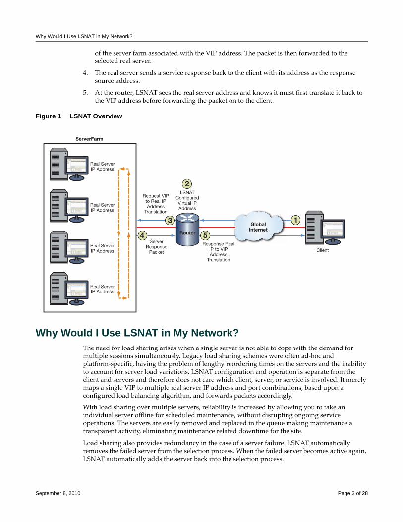
Why Would I Use LSNAT in My Network?
of the server farm associated with the VIP address. The packet is then forwarded to the selected real server.
4. The real server sends a service response back to the client with its address as the response source address.
5. At the router, LSNAT sees the real server address and knows it must first translate it back to the VIP address before forwarding the packet on to the client.
Figure 1 LSNAT Overview
Why Would I Use LSNAT in My Network?The need for load sharing arises when a single server is not able to cope with the demand for multiple sessions simultaneously. Legacy load sharing schemes were often ad‐hoc and platform‐specific, having the problem of lengthy reordering times on the servers and the inability to account for server load variations. LSNAT configuration and operation is separate from the client and servers and therefore does not care which client, server, or service is involved. It merely maps a single VIP to multiple real server IP address and port combinations, based upon a configured load balancing algorithm, and forwards packets accordingly.
With load sharing over multiple servers, reliability is increased by allowing you to take an individual server offline for scheduled maintenance, without disrupting ongoing service operations. The servers are easily removed and replaced in the queue making maintenance a transparent activity, eliminating maintenance related downtime for the site.
Load sharing also provides redundancy in the case of a server failure. LSNAT automatically removes the failed server from the selection process. When the failed server becomes active again, LSNAT automatically adds the server back into the selection process.
Real ServerIP Address
Request VIPto Real IPAddress
Translation
LSNATConfiguredVirtual IPAddress
ServerResponse
Packet
Response RealIP to VIPAddress
Translation
Client
Real ServerIP Address
Real ServerIP Address
Real ServerIP Address
al
GlobalInternet
ServerFarm
1
4 5
2
3
Router
September 8, 2010 Page 2 of 28
How Can I Implement LSNAT?
Server and TCP/UDP port verification can ensure that the ports used by LSNAT are operational. TCP/UPD port service verification is capable of determining whether a server is active before creating a session. This feature eliminates the point of failure vulnerability by automatically recognizing a server is down and taking it out of the LSNAT load balancing process.
Security is improved since only the VIP is known, not the specific server addresses, ensuring that only the appropriate traffic goes to the servers.
LSNAT improves network performance by leveling traffic over many systems. Using LSNAT in conjunction with Aggregate Links removes the performance bottleneck and reliability concerns of one physical link to a server by bundling multiple links, with fail over if a link goes down. Utilizing the IP‐Policy and QoS features of the S‐Series and N‐Series devices with the LSNAT feature further improves the performance and security of the network. When tied with the Virtual Redundant Router Protocol (VRRP), the network becomes even more reliable and secure.
For all these reasons, LSNAT is ideal for enterprise account web servers, application servers, or database servers.
How Can I Implement LSNAT?To implement LSNAT in your network:
1. Configure one or more server farms by:
– Specifying a server farm name
– Configuring real servers as members of the server farm
– Specifying a load balancing algorithm for each server farm
2. Configure each real server by:
– Optionally configuring real server fail‐detect settings
– Optionally limiting the maximum number of active connections for this real server
– Optionally specifying a round robin weight value for this real server
– Enabling the real server for service
3. Configure a virtual server by:
– Specifying a virtual server name
– Associating a virtual server with a server farm
– Configuring a virtual server IP address (VIP)
– Optionally restricting access to specific virtual server clients
– Optionally specifying a sticky type and idle timeout
– Enabling the virtual server for service
4. Configure global virtual server settings by:
– Optionally defining a non‐standard FTP port to be used by virtual servers
– Optionally allowing all clients to directly access all services provided by real servers
5. Manage a real server by optionally clearing load balancing connections or statistics
September 8, 2010 Page 3 of 28
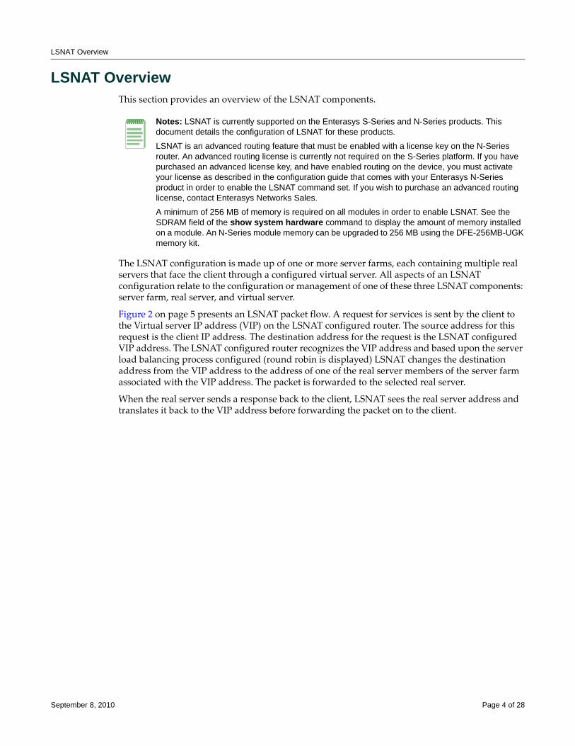
LSNAT Overview
LSNAT OverviewThis section provides an overview of the LSNAT components.
The LSNAT configuration is made up of one or more server farms, each containing multiple real servers that face the client through a configured virtual server. All aspects of an LSNAT configuration relate to the configuration or management of one of these three LSNAT components: server farm, real server, and virtual server.
Figure 2 on page 5 presents an LSNAT packet flow. A request for services is sent by the client to the Virtual server IP address (VIP) on the LSNAT configured router. The source address for this request is the client IP address. The destination address for the request is the LSNAT configured VIP address. The LSNAT configured router recognizes the VIP address and based upon the server load balancing process configured (round robin is displayed) LSNAT changes the destination address from the VIP address to the address of one of the real server members of the server farm associated with the VIP address. The packet is forwarded to the selected real server.
When the real server sends a response back to the client, LSNAT sees the real server address and translates it back to the VIP address before forwarding the packet on to the client.
Notes: LSNAT is currently supported on the Enterasys S-Series and N-Series products. This document details the configuration of LSNAT for these products.
LSNAT is an advanced routing feature that must be enabled with a license key on the N-Series router. An advanced routing license is currently not required on the S-Series platform. If you have purchased an advanced license key, and have enabled routing on the device, you must activate your license as described in the configuration guide that comes with your Enterasys N-Series product in order to enable the LSNAT command set. If you wish to purchase an advanced routing license, contact Enterasys Networks Sales.
A minimum of 256 MB of memory is required on all modules in order to enable LSNAT. See the SDRAM field of the show system hardware command to display the amount of memory installed on a module. An N-Series module memory can be upgraded to 256 MB using the DFE-256MB-UGK memory kit.
September 8, 2010 Page 4 of 28
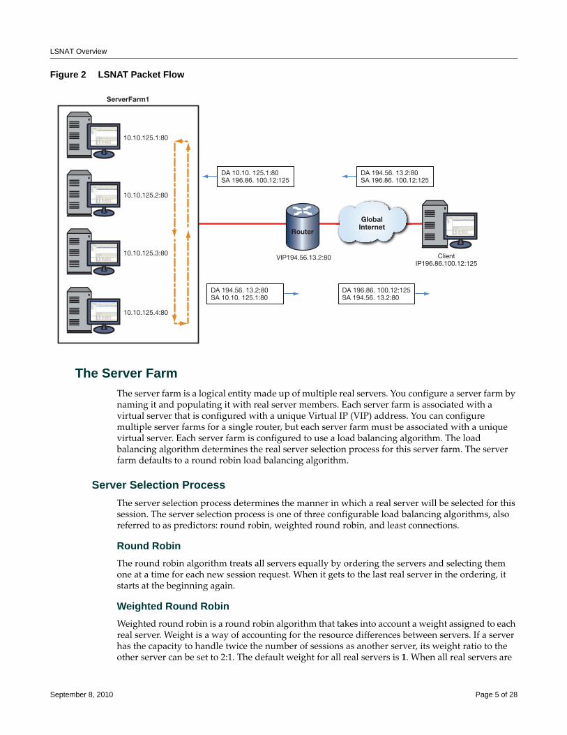
LSNAT Overview
Figure 2 LSNAT Packet Flow
The Server FarmThe server farm is a logical entity made up of multiple real servers. You configure a server farm by naming it and populating it with real server members. Each server farm is associated with a virtual server that is configured with a unique Virtual IP (VIP) address. You can configure multiple server farms for a single router, but each server farm must be associated with a unique virtual server. Each server farm is configured to use a load balancing algorithm. The load balancing algorithm determines the real server selection process for this server farm. The server farm defaults to a round robin load balancing algorithm.
Server Selection ProcessThe server selection process determines the manner in which a real server will be selected for this session. The server selection process is one of three configurable load balancing algorithms, also referred to as predictors: round robin, weighted round robin, and least connections.
Round RobinThe round robin algorithm treats all servers equally by ordering the servers and selecting them one at a time for each new session request. When it gets to the last real server in the ordering, it starts at the beginning again.
Weighted Round RobinWeighted round robin is a round robin algorithm that takes into account a weight assigned to each real server. Weight is a way of accounting for the resource differences between servers. If a server has the capacity to handle twice the number of sessions as another server, its weight ratio to the other server can be set to 2:1. The default weight for all real servers is 1. When all real servers are
10.10.125.1:80
10.10.125.2:80
10.10.125.3:80
10.10.125.4:80
DA 196.86. 100.12:125SA 194.56. 13.2:80
ClientIP196.86.100.12:125
VIP194.56.13.2:80
GlobalInternet
ServerFarm1
Router
DA 10.10. 125.1:80SA 196.86. 100.12:125
DA 194.56. 13.2:80SA 196.86. 100.12:125
DA 194.56. 13.2:80SA 10.10. 125.1:80
September 8, 2010 Page 5 of 28
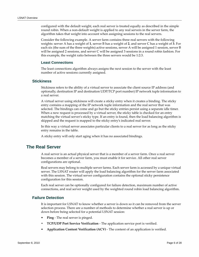
LSNAT Overview
configured with the default weight, each real server is treated equally as described in the simple round robin. When a non‐default weight is applied to any real servers in the server farm, the algorithm takes that weight into account when assigning sessions to the real servers.
Consider the following example. A server farm contains three real servers with the following weights: server A has a weight of 1, server B has a weight of 2, and server C has a weight of 3. For each six (the sum of the three weights) active sessions, server A will be assigned 1 session, server B will be assigned 2 sessions, and server C will be assigned 3 sessions in a round robin fashion. For this example, the weight ratio between the three servers would be 1:2:3.
Least ConnectionsThe least connections algorithm always assigns the next session to the server with the least number of active sessions currently assigned.
StickinessStickiness refers to the ability of a virtual server to associate the client source IP address (and optionally, destination IP and destination UDP/TCP port number) IP network tuple information to a real server.
A virtual server using stickiness will create a sticky entry when it creates a binding. The sticky entry contains a mapping of the IP network tuple information and the real server that was selected. The bindings can come and go but the sticky entries persist using a separate idle timer. When a new request is processed by a virtual server, the sticky table is checked for an entry matching the virtual serverʹs sticky type. If an entry is found, then the load balancing algorithm is skipped and the request is mapped to the sticky entry’s indicated real server.
In this way a virtual server associates particular clients to a real server for as long as the sticky entry remains in the table.
A sticky entry will only start aging when it has no associated bindings.
The Real ServerA real server is an actual physical server that is a member of a server farm. Once a real server becomes a member of a server farm, you must enable it for service. All other real server configurations are optional.
Real servers may belong to multiple server farms. Each server farm is accessed by a unique virtual server. The LSNAT router will apply the load balancing algorithm for the server farm associated with this session. The virtual server configuration contains the optional sticky persistence configuration for this session.
Each real server can be optionally configured for failure detection, maximum number of active connections, and real server weight used by the weighted round robin load balancing algorithm.
Failure DetectionIt is important for LSNAT to know whether a server is down so it can be removed from the server selection process. There are a number of methods to determine whether a real server is up or down before being selected for a potential LSNAT session:
• Ping ‐ The real server is pinged.
• TCP/UDP Port Service Verification ‐ The application service port is verified.
• Application Content Verification (ACV) ‐ The content of an application is verified.
September 8, 2010 Page 6 of 28
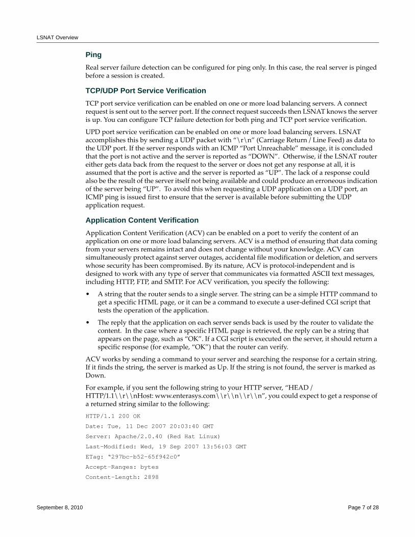
LSNAT Overview
PingReal server failure detection can be configured for ping only. In this case, the real server is pinged before a session is created.
TCP/UDP Port Service VerificationTCP port service verification can be enabled on one or more load balancing servers. A connect request is sent out to the server port. If the connect request succeeds then LSNAT knows the server is up. You can configure TCP failure detection for both ping and TCP port service verification.
UPD port service verification can be enabled on one or more load balancing servers. LSNAT accomplishes this by sending a UDP packet with “\r\n” (Carriage Return / Line Feed) as data to the UDP port. If the server responds with an ICMP “Port Unreachable” message, it is concluded that the port is not active and the server is reported as “DOWN”. Otherwise, if the LSNAT router either gets data back from the request to the server or does not get any response at all, it is assumed that the port is active and the server is reported as “UP”. The lack of a response could also be the result of the server itself not being available and could produce an erroneous indication of the server being “UP”. To avoid this when requesting a UDP application on a UDP port, an ICMP ping is issued first to ensure that the server is available before submitting the UDP application request.
Application Content VerificationApplication Content Verification (ACV) can be enabled on a port to verify the content of an application on one or more load balancing servers. ACV is a method of ensuring that data coming from your servers remains intact and does not change without your knowledge. ACV can simultaneously protect against server outages, accidental file modification or deletion, and servers whose security has been compromised. By its nature, ACV is protocol‐independent and is designed to work with any type of server that communicates via formatted ASCII text messages, including HTTP, FTP, and SMTP. For ACV verification, you specify the following:
• A string that the router sends to a single server. The string can be a simple HTTP command to get a specific HTML page, or it can be a command to execute a user‐defined CGI script that tests the operation of the application.
• The reply that the application on each server sends back is used by the router to validate the content. In the case where a specific HTML page is retrieved, the reply can be a string that appears on the page, such as “OK”. If a CGI script is executed on the server, it should return a specific response (for example, “OK”) that the router can verify.
ACV works by sending a command to your server and searching the response for a certain string. If it finds the string, the server is marked as Up. If the string is not found, the server is marked as Down.
For example, if you sent the following string to your HTTP server, “HEAD / HTTP/1.1\\r\\nHost: www.enterasys.com\\r\\n\\r\\n”, you could expect to get a response of a returned string similar to the following:
HTTP/1.1 200 OK
Date: Tue, 11 Dec 2007 20:03:40 GMT
Server: Apache/2.0.40 (Red Hat Linux)
Last-Modified: Wed, 19 Sep 2007 13:56:03 GMT
ETag: “297bc-b52-65f942c0”
Accept-Ranges: bytes
Content-Length: 2898
September 8, 2010 Page 7 of 28
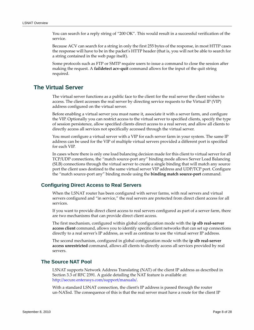
LSNAT Overview
You can search for a reply string of “200 OK”. This would result in a successful verification of the service.
Because ACV can search for a string in only the first 255 bytes of the response, in most HTTP cases the response will have to be in the packetʹs HTTP header (that is, you will not be able to search for a string contained in the web page itself).
Some protocols such as FTP or SMTP require users to issue a command to close the session after making the request. A faildetect acv‐quit command allows for the input of the quit string required.
The Virtual ServerThe virtual server functions as a public face to the client for the real server the client wishes to access. The client accesses the real server by directing service requests to the Virtual IP (VIP) address configured on the virtual server.
Before enabling a virtual server you must name it, associate it with a server farm, and configure the VIP. Optionally you can restrict access to the virtual server to specified clients, specify the type of session persistence, allow specified clients direct access to a real server, and allow all clients to directly access all services not specifically accessed through the virtual server.
You must configure a virtual server with a VIP for each server farm in your system. The same IP address can be used for the VIP of multiple virtual servers provided a different port is specified for each VIP.
In cases where there is only one load balancing decision made for this client to virtual server for all TCP/UDP connections, the “match source‐port any” binding mode allows Server Load Balancing (SLB) connections through the virtual server to create a single binding that will match any source port the client uses destined to the same virtual server VIP address and UDP/TCP port. Configure the “match source‐port any” binding mode using the binding match source‐port command.
Configuring Direct Access to Real ServersWhen the LSNAT router has been configured with server farms, with real servers and virtual servers configured and “in service,” the real servers are protected from direct client access for all services.
If you want to provide direct client access to real servers configured as part of a server farm, there are two mechanisms that can provide direct client access.
The first mechanism, configured within global configuration mode with the ip slb real‐server access client command, allows you to identify specific client networks that can set up connections directly to a real server’s IP address, as well as continue to use the virtual server IP address.
The second mechanism, configured in global configuration mode with the ip slb real‐server access unrestricted command, allows all clients to directly access all services provided by real servers.
The Source NAT PoolLSNAT supports Network Address Translating (NAT) of the client IP address as described in Section 3.3 of RFC 2391. A guide detailing the NAT feature is available at: http://secure.enterasys.com/support/manuals/.
With a standard LSNAT connection, the client’s IP address is passed through the router un‐NATed. The consequence of this is that the real server must have a route for the client IP
September 8, 2010 Page 8 of 28
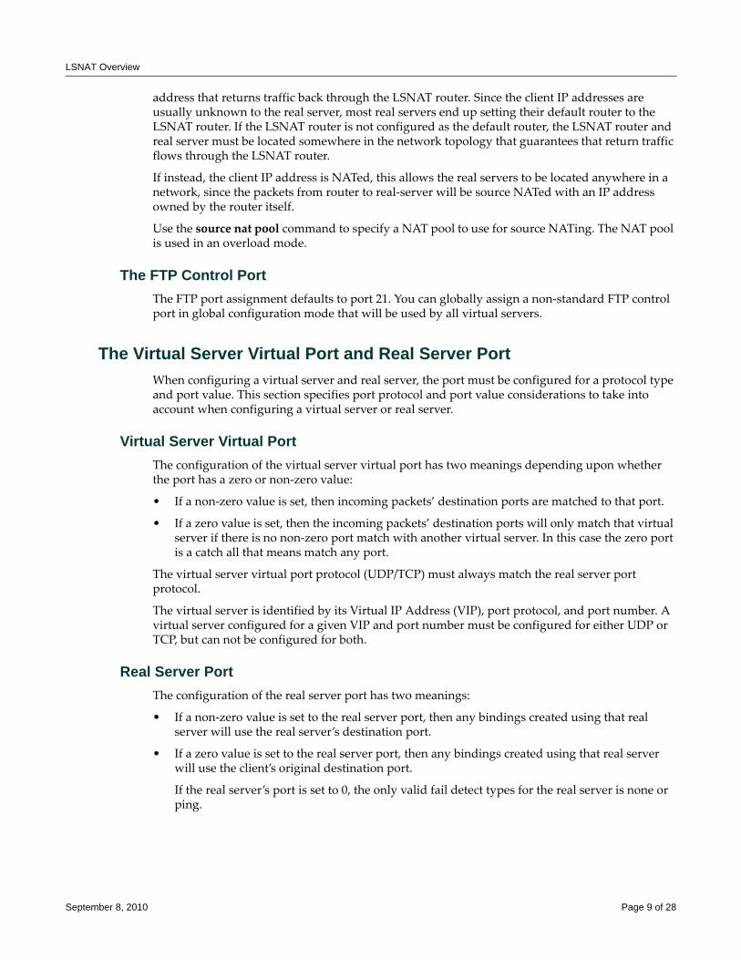
LSNAT Overview
address that returns traffic back through the LSNAT router. Since the client IP addresses are usually unknown to the real server, most real servers end up setting their default router to the LSNAT router. If the LSNAT router is not configured as the default router, the LSNAT router and real server must be located somewhere in the network topology that guarantees that return traffic flows through the LSNAT router.
If instead, the client IP address is NATed, this allows the real servers to be located anywhere in a network, since the packets from router to real‐server will be source NATed with an IP address owned by the router itself.
Use the source nat pool command to specify a NAT pool to use for source NATing. The NAT pool is used in an overload mode.
The FTP Control PortThe FTP port assignment defaults to port 21. You can globally assign a non‐standard FTP control port in global configuration mode that will be used by all virtual servers.
The Virtual Server Virtual Port and Real Server PortWhen configuring a virtual server and real server, the port must be configured for a protocol type and port value. This section specifies port protocol and port value considerations to take into account when configuring a virtual server or real server.
Virtual Server Virtual PortThe configuration of the virtual server virtual port has two meanings depending upon whether the port has a zero or non‐zero value:
• If a non‐zero value is set, then incoming packets’ destination ports are matched to that port.
• If a zero value is set, then the incoming packets’ destination ports will only match that virtual server if there is no non‐zero port match with another virtual server. In this case the zero port is a catch all that means match any port.
The virtual server virtual port protocol (UDP/TCP) must always match the real server port protocol.
The virtual server is identified by its Virtual IP Address (VIP), port protocol, and port number. A virtual server configured for a given VIP and port number must be configured for either UDP or TCP, but can not be configured for both.
Real Server PortThe configuration of the real server port has two meanings:
• If a non‐zero value is set to the real server port, then any bindings created using that real server will use the real server’s destination port.
• If a zero value is set to the real server port, then any bindings created using that real server will use the client’s original destination port.
If the real server’s port is set to 0, the only valid fail detect types for the real server is none or ping.
September 8, 2010 Page 9 of 28
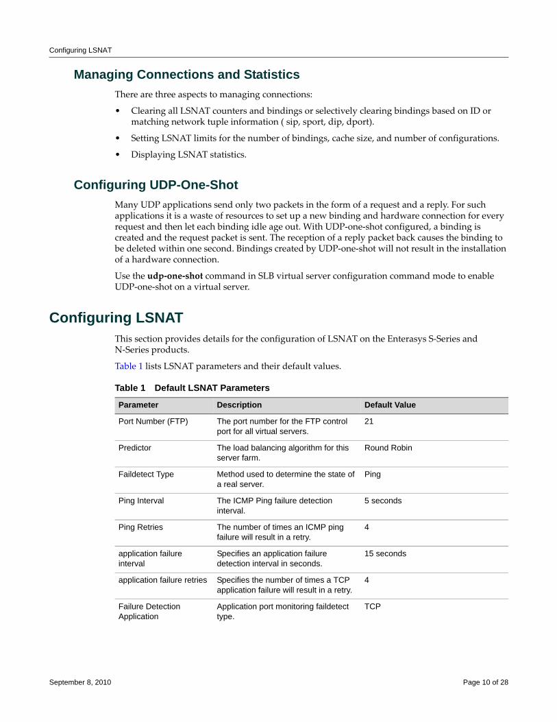
Configuring LSNAT
Managing Connections and StatisticsThere are three aspects to managing connections:
• Clearing all LSNAT counters and bindings or selectively clearing bindings based on ID or matching network tuple information ( sip, sport, dip, dport).
• Setting LSNAT limits for the number of bindings, cache size, and number of configurations.
• Displaying LSNAT statistics.
Configuring UDP-One-ShotMany UDP applications send only two packets in the form of a request and a reply. For such applications it is a waste of resources to set up a new binding and hardware connection for every request and then let each binding idle age out. With UDP‐one‐shot configured, a binding is created and the request packet is sent. The reception of a reply packet back causes the binding to be deleted within one second. Bindings created by UDP‐one‐shot will not result in the installation of a hardware connection.
Use the udp‐one‐shot command in SLB virtual server configuration command mode to enable UDP‐one‐shot on a virtual server.
Configuring LSNATThis section provides details for the configuration of LSNAT on the Enterasys S‐Series and N‐Series products.
Table 1 lists LSNAT parameters and their default values.
Table 1 Default LSNAT Parameters
Parameter Description Default Value
Port Number (FTP) The port number for the FTP control port for all virtual servers.
21
Predictor The load balancing algorithm for this server farm.
Round Robin
Faildetect Type Method used to determine the state of a real server.
Ping
Ping Interval The ICMP Ping failure detection interval.
5 seconds
Ping Retries The number of times an ICMP ping failure will result in a retry.
4
application failure interval
Specifies an application failure detection interval in seconds.
15 seconds
application failure retries Specifies the number of times a TCP application failure will result in a retry.
4
Failure Detection Application
Application port monitoring faildetect type.
TCP
September 8, 2010 Page 10 of 28
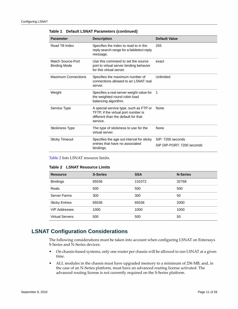
Configuring LSNAT
Table 2 lists LSNAT resource limits.
LSNAT Configuration ConsiderationsThe following considerations must be taken into account when configuring LSNAT on Enterasys S‐Series and N‐Series devices:
• On chassis‐based systems, only one router per chassis will be allowed to run LSNAT at a given time.
• ALL modules in the chassis must have upgraded memory to a minimum of 256 MB, and, in the case of an N‐Series platform, must have an advanced routing license activated. The advanced routing license is not currently required on the S‐Series platform.
Read Till Index Specifies the index to read to in the reply search range for a faildetect reply message.
255
Match Source-Port Binding Mode
Use this command to set the source port to virtual server binding behavior for this virtual server.
exact
Maximum Connections Specifies the maximum number of connections allowed to an LSNAT real server.
Unlimited
Weight Specifies a real server weight value for the weighted round robin load balancing algorithm.
1
Service Type A special service type, such as FTP or TFTP, if the virtual port number is different than the default for that service.
None
Stickiness Type The type of stickiness to use for the virtual server.
None
Sticky Timeout Specifies the age out interval for sticky entries that have no associated bindings.
SIP: 7200 seconds
SIP DIP-PORT: 7200 seconds
Table 2 LSNAT Resource Limits
Resource S-Series SSA N-Series
Bindings 65536 131072 32768
Reals 500 500 500
Server Farms 300 300 50
Sticky Entries 65536 65536 2000
VIP Addresses 1000 1000 1000
Virtual Servers 500 500 50
Table 1 Default LSNAT Parameters (continued)
Parameter Description Default Value
September 8, 2010 Page 11 of 28
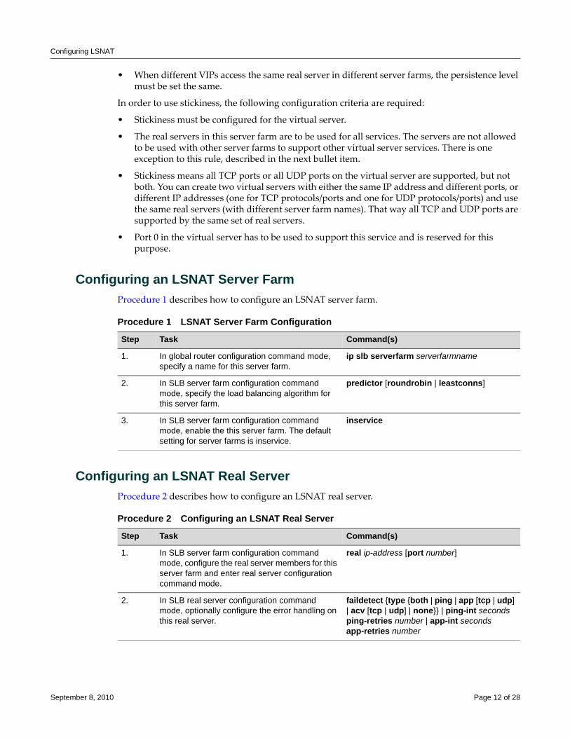
Configuring LSNAT
• When different VIPs access the same real server in different server farms, the persistence level must be set the same.
In order to use stickiness, the following configuration criteria are required:
• Stickiness must be configured for the virtual server.
• The real servers in this server farm are to be used for all services. The servers are not allowed to be used with other server farms to support other virtual server services. There is one exception to this rule, described in the next bullet item.
• Stickiness means all TCP ports or all UDP ports on the virtual server are supported, but not both. You can create two virtual servers with either the same IP address and different ports, or different IP addresses (one for TCP protocols/ports and one for UDP protocols/ports) and use the same real servers (with different server farm names). That way all TCP and UDP ports are supported by the same set of real servers.
• Port 0 in the virtual server has to be used to support this service and is reserved for this purpose.
Configuring an LSNAT Server FarmProcedure 1 describes how to configure an LSNAT server farm.
Configuring an LSNAT Real ServerProcedure 2 describes how to configure an LSNAT real server.
Procedure 1 LSNAT Server Farm Configuration
Step Task Command(s)
1. In global router configuration command mode, specify a name for this server farm.
ip slb serverfarm serverfarmname
2. In SLB server farm configuration command mode, specify the load balancing algorithm for this server farm.
predictor [roundrobin | leastconns]
3. In SLB server farm configuration command mode, enable the this server farm. The default setting for server farms is inservice.
inservice
Procedure 2 Configuring an LSNAT Real Server
Step Task Command(s)
1. In SLB server farm configuration command mode, configure the real server members for this server farm and enter real server configuration command mode.
real ip-address [port number]
2. In SLB real server configuration command mode, optionally configure the error handling on this real server.
faildetect {type {both | ping | app [tcp | udp] | acv [tcp | udp] | none}} | ping-int seconds ping-retries number | app-int seconds app-retries number
September 8, 2010 Page 12 of 28
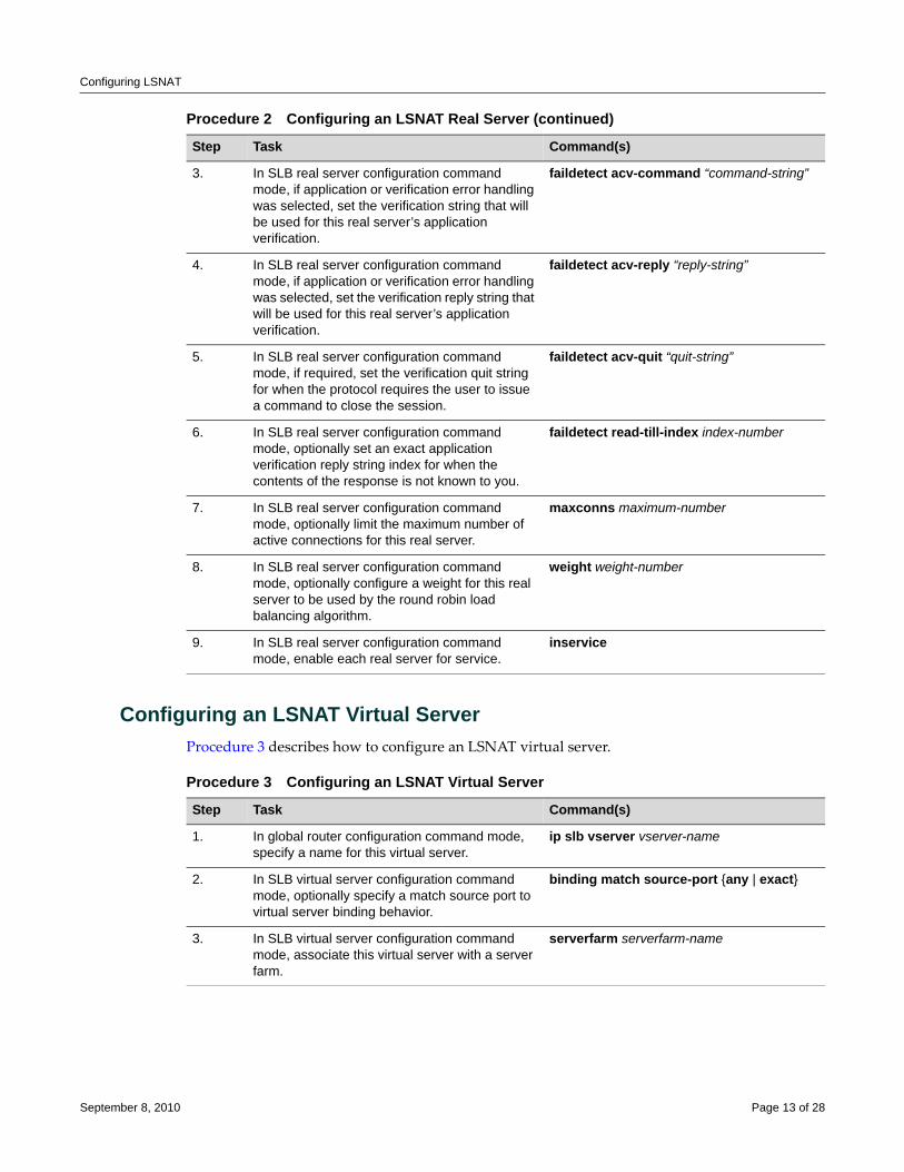
Configuring LSNAT
Configuring an LSNAT Virtual ServerProcedure 3 describes how to configure an LSNAT virtual server.
3. In SLB real server configuration command mode, if application or verification error handling was selected, set the verification string that will be used for this real server’s application verification.
faildetect acv-command “command-string”
4. In SLB real server configuration command mode, if application or verification error handling was selected, set the verification reply string that will be used for this real server’s application verification.
faildetect acv-reply “reply-string”
5. In SLB real server configuration command mode, if required, set the verification quit string for when the protocol requires the user to issue a command to close the session.
faildetect acv-quit “quit-string”
6. In SLB real server configuration command mode, optionally set an exact application verification reply string index for when the contents of the response is not known to you.
faildetect read-till-index index-number
7. In SLB real server configuration command mode, optionally limit the maximum number of active connections for this real server.
maxconns maximum-number
8. In SLB real server configuration command mode, optionally configure a weight for this real server to be used by the round robin load balancing algorithm.
weight weight-number
9. In SLB real server configuration command mode, enable each real server for service.
inservice
Procedure 2 Configuring an LSNAT Real Server (continued)
Step Task Command(s)
Procedure 3 Configuring an LSNAT Virtual Server
Step Task Command(s)
1. In global router configuration command mode, specify a name for this virtual server.
ip slb vserver vserver-name
2. In SLB virtual server configuration command mode, optionally specify a match source port to virtual server binding behavior.
binding match source-port {any | exact}
3. In SLB virtual server configuration command mode, associate this virtual server with a server farm.
serverfarm serverfarm-name
September 8, 2010 Page 13 of 28
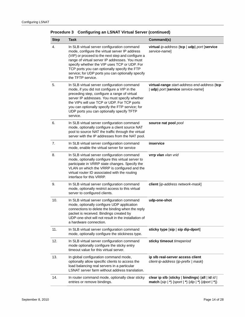
Configuring LSNAT
4. In SLB virtual server configuration command mode, configure the virtual server IP address (VIP) or proceed to the next step and configure a range of virtual server IP addresses. You must specify whether the VIP uses TCP or UDP. For TCP ports you can optionally specify the FTP service; for UDP ports you can optionally specify the TFTP service.
virtual ip-address {tcp | udp} port [service service-name]
5. In SLB virtual server configuration command mode, if you did not configure a VIP in the preceding step, configure a range of virtual server IP addresses. You must specify whether the VIPs will use TCP or UDP. For TCP ports you can optionally specify the FTP service; for UDP ports you can optionally specify TFTP service.
virtual-range start-address end-address {tcp | udp} port [service service-name]
6. In SLB virtual server configuration command mode, optionally configure a client source NAT pool to source NAT the traffic through the virtual server with the IP addresses from the NAT pool.
source nat pool pool
7. In SLB virtual server configuration command mode, enable the virtual server for service
inservice
8. In SLB virtual server configuration command mode, optionally configure this virtual server to participate in VRRP state changes. Specify the VLAN on which the VRRP is configured and the virtual router ID associated with the routing interface for this VRRP.
vrrp vlan vlan vrid
9. In SLB virtual server configuration command mode, optionally restrict access to this virtual server to configured clients.
client [ip-address network-mask]
10. In SLB virtual server configuration command mode, optionally configure UDP application connections to delete the binding when the reply packet is received. Bindings created by UDP-one-shot will not result in the installation of a hardware connection.
udp-one-shot
11. In SLB virtual server configuration command mode, optionally configure the stickiness type.
sticky type [sip | sip dip-dport]
12. In SLB virtual server configuration command mode optionally configure the sticky entry timeout value for this virtual server.
sticky timeout timeperiod
13. In global configuration command mode, optionally allow specific clients to access the load balancing real servers in a particular LSNAT server farm without address translation.
ip slb real-server access client client-ip-address {ip-prefix | mask}
14. In router command mode, optionally clear sticky entries or remove bindings.
clear ip slb {sticky | bindings} {all | id id | match {sip | *} {sport | *} {dip | *} {dport | *}}
Procedure 3 Configuring an LSNAT Virtual Server (continued)
Step Task Command(s)
September 8, 2010 Page 14 of 28
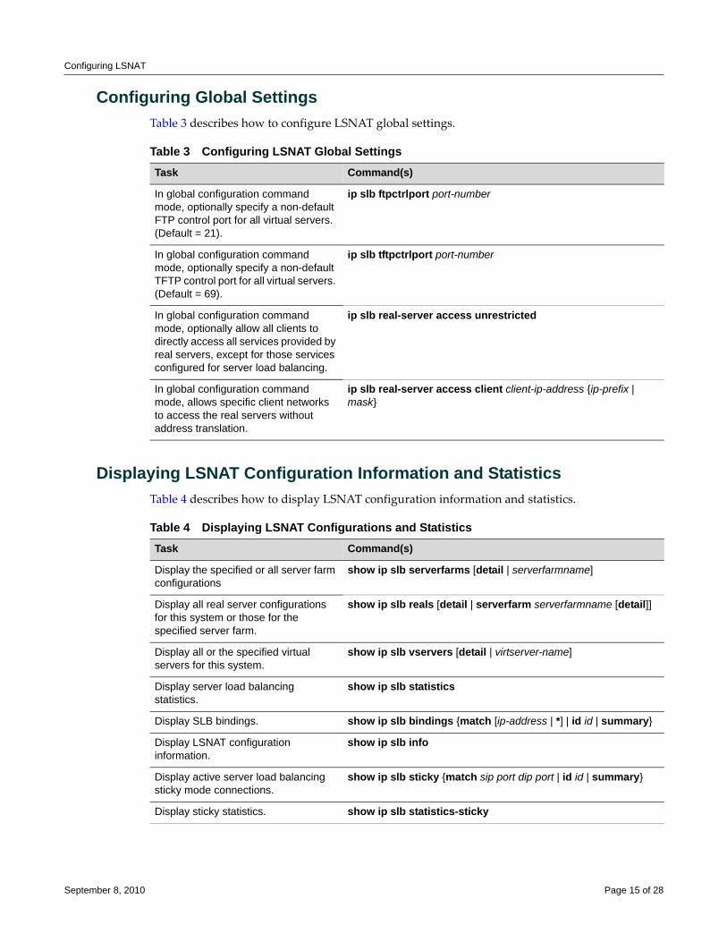
Configuring LSNAT
Configuring Global SettingsTable 3 describes how to configure LSNAT global settings.
Displaying LSNAT Configuration Information and StatisticsTable 4 describes how to display LSNAT configuration information and statistics.
Table 3 Configuring LSNAT Global SettingsTask Command(s)
In global configuration command mode, optionally specify a non-default FTP control port for all virtual servers. (Default = 21).
ip slb ftpctrlport port-number
In global configuration command mode, optionally specify a non-default TFTP control port for all virtual servers. (Default = 69).
ip slb tftpctrlport port-number
In global configuration command mode, optionally allow all clients to directly access all services provided by real servers, except for those services configured for server load balancing.
ip slb real-server access unrestricted
In global configuration command mode, allows specific client networks to access the real servers without address translation.
ip slb real-server access client client-ip-address {ip-prefix | mask}
Table 4 Displaying LSNAT Configurations and StatisticsTask Command(s)
Display the specified or all server farm configurations
show ip slb serverfarms [detail | serverfarmname]
Display all real server configurations for this system or those for the specified server farm.
show ip slb reals [detail | serverfarm serverfarmname [detail]]
Display all or the specified virtual servers for this system.
show ip slb vservers [detail | virtserver-name]
Display server load balancing statistics.
show ip slb statistics
Display SLB bindings. show ip slb bindings {match [ip-address | *] | id id | summary}
Display LSNAT configuration information.
show ip slb info
Display active server load balancing sticky mode connections.
show ip slb sticky {match sip port dip port | id id | summary}
Display sticky statistics. show ip slb statistics-sticky
September 8, 2010 Page 15 of 28
LSNAT Configuration Example
LSNAT Configuration ExampleThis section provides an enterprise LSNAT configuration example that includes five server farms. These server farms can be logically thought of as either product‐based or enterprise internal server farms. The product‐based server farms are accessible to the general public. The enterprise internal server farms are accessible only to enterprise employees. The myproduct HTTP and FTP server farms provide the product‐based services. The myinternal HTTP, FTP, and SMTP server farms provide enterprise internal services.
Product-Based and Enterprise Internal DomainsThe HTTP and FTP domains providing public access to the product‐based server farms are:
• www.myproduct.com
• ftp.myproduct.com
The HTTP, FTP, and SMTP domains providing employee access to the enterprise internal server farms are:
• www.myinternal.com
• ftp.myinternal.com
• smtp.myinternal.com
Server FarmsFor both the public product‐based and enterprise internal server farms, the enterprise IT clients will have direct access to the servers without any address translation required. All other clients that have access rights to these server farms will be address translated.
Product-Based HTTP Server FarmThe product‐based HTTP server farm, real server and virtual server configuration will:
• Handle HTTP requests from the general public using the www.myproduct.com domain.
• Load balance HTTP services across the three real servers associated with www.myproduct.com, using the weighted round robin selection process with a ratio of 3:2:2. The weighted round robin selection process takes into account the resource differences between the three servers.
• Use Application Content Verification TCP failure detection.
• Use the VIP 194.56.12.2 port 80.
Product-Based FTP Server FarmThe product‐based FTP server farm, real server and virtual server configuration will:
• Handle FTP requests from the general public using the ftp.myproduct.com domain.
• Load balance FTP services using the least connections predictor across two real servers.
• Use both ping and TCP application failure detection.
• Use the VIP 194.56.12.2 port 21.
September 8, 2010 Page 16 of 28
LSNAT Configuration Example
Enterprise Internal HTTP Server FarmThe enterprise internal HTTP server farm, real server and virtual server configuration will:
• Handle HTTP requests from enterprise employees using the www.myinternal.com domain.
• Load balance HTTP services across two real servers, using the simple round robin selection process.
• Use Application Content Verification TCP failure detection.
• Use the VIP 194.56.13.3 port 80.
Enterprise Internal FTP Server FarmThe enterprise internal FTP server farm, real server and virtual server configuration will:
• Handle FTP requests from enterprise employees using the ftp.myinternal.com domain.
• Load balance FTP services using the least connections predictor across two real servers.
• Use both ping and TCP application failure detection.
• Use the VIP 194.56.13.3 port 21.
Enterprise Internal SMTP Server FarmThe enterprise internal SMTP server farm, real server and virtual server configuration will:
• Handle SMTP requests from the enterprise employees using the smtp.myproduct.com domain.
• Load balance SMTP services across two real servers, using the simple round robin selection process.
• Use both the ping and TCP application failure detection.
• Use the VIP 194.56.13.3 port 25.
See Figure 3 on page 18 for a presentation of this LSNAT configuration.
September 8, 2010 Page 17 of 28
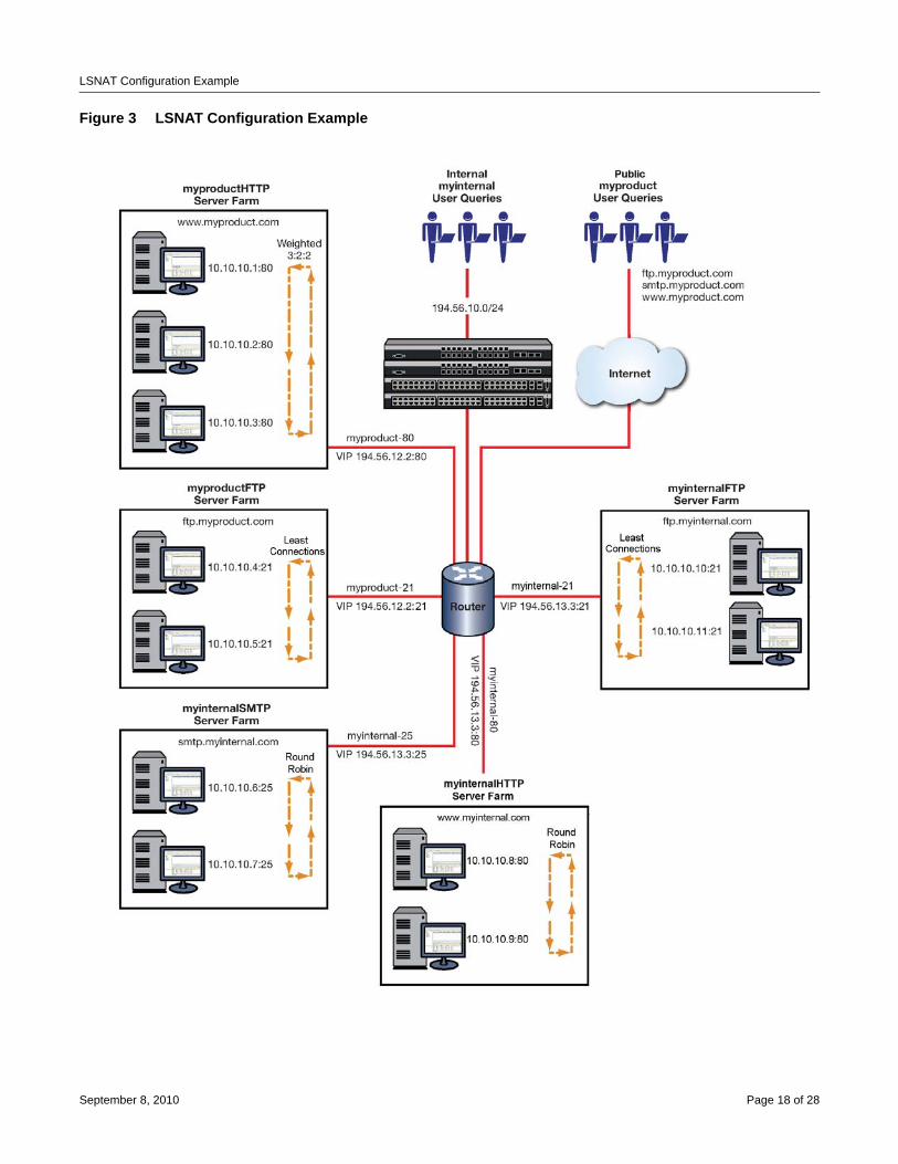
LSNAT Configuration Example
Figure 3 LSNAT Configuration Example
September 8, 2010 Page 18 of 28
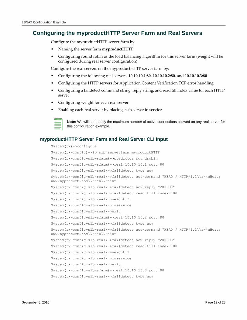
LSNAT Configuration Example
Configuring the myproductHTTP Server Farm and Real ServersConfigure the myproductHTTP server farm by:
• Naming the server farm myproductHTTP
• Configuring round robin as the load balancing algorithm for this server farm (weight will be configured during real server configuration)
Configure the real servers on the myproductHTTP server farm by:
• Configuring the following real servers: 10.10.10.1:80, 10.10.10.2:80, and 10.10.10.3:80
• Configuring the HTTP servers for Application Content Verification TCP error handling
• Configuring a faildetect command string, reply string, and read till index value for each HTTP server
• Configuring weight for each real server
• Enabling each real server by placing each server in service
myproductHTTP Server Farm and Real Server CLI InputSystem(rw)->configure
System(rw-config)->ip slb serverfarm myproductHTTP
System(rw-config-slb-sfarm)->predictor roundrobin
System(rw-config-slb-sfarm)->real 10.10.10.1 port 80
System(rw-config-slb-real)->faildetect type acv
System(rw-config-slb-real)->faildetect acv-command “HEAD / HTTP/1.1\\r\\nHost: www.myproduct.com\\r\\n\\r\\n”
System(rw-config-slb-real)->faildetect acv-reply “200 OK”
System(rw-config-slb-real)->faildetect read-till-index 100
System(rw-config-slb-real)->weight 3
System(rw-config-slb-real)->inservice
System(rw-config-slb-real)->exit
System(rw-config-slb-sfarm)->real 10.10.10.2 port 80
System(rw-config-slb-real)->faildetect type acv
System(rw-config-slb-real)->faildetect acv-command “HEAD / HTTP/1.1\\r\\nHost: www.myproduct.com\\r\\n\\r\\n”
System(rw-config-slb-real)->faildetect acv-reply “200 OK”
System(rw-config-slb-real)->faildetect read-till-index 100
System(rw-config-slb-real)->weight 2
System(rw-config-slb-real)->inservice
System(rw-config-slb-real)->exit
System(rw-config-slb-sfarm)->real 10.10.10.3 port 80
System(rw-config-slb-real)->faildetect type acv
Note: We will not modify the maximum number of active connections allowed on any real server for this configuration example.
September 8, 2010 Page 19 of 28
LSNAT Configuration Example
System(rw-config-slb-real)->faildetect acv-command “HEAD / HTTP/1.1\\r\\nHost: www.myproduct.com\\r\\n\\r\\n”
System(rw-config-slb-real)->faildetect acv-reply “200 OK”
System(rw-config-slb-real)->faildetect read-till-index 100
System(rw-config-slb-real)->weight 2
System(rw-config-slb-real)->inservice
System(rw-config-slb-real)->exit
System(rw-config-slb-sfarm)->exit
System(rw-config)->
Configuring myproduct-80 Virtual ServerConfigure the virtual server for the myproductHTTP server farm by:
• Naming the virtual server myproduct‐80
• Associating the virtual server with the myproductHTTP server farm
• Assigning the virtual server IP address with the TCP protocol for www (port 80)
• Setting the idle timeout value of 360 seconds
• Placing the virtual server in service
myproduct-80 Virtual Server CLI InputSystem(rw-config)->ip slb vserver myproduct-80
System(rw-config-slb-vserver)->serverfarm myproductHTTP
System(rw-config-slb-vserver)->virtual 194.56.12.2 tcp www
System(rw-config-slb-vserver)->idle timeout 360
System(rw-config-slb-vserver)->inservice
System(rw-config-slb-vserver)->exit
System(rw-config)->
Configuring the myproductFTP Server Farm and Real ServersConfigure the myproductFTP server farm by:
• Naming the server farm myproductFTP
• Configuring least connections as the load balancing algorithm for this server farm
Configure the real servers on the myproductFTP server farm by:
• Configuring the following real servers: 10.10.10.4:21 and 10.10.10.5:21
• Configuring the FTP servers for both ping and TCP port service verification
• Enabling each real server by placing each server in service
Notes: We will not modify the maximum number of active connections allowed on any real server for this configuration example.
September 8, 2010 Page 20 of 28
LSNAT Configuration Example
myproductFTP Server Farm and Real Server CLI InputSystem(rw-config)->ip slb serverfarm myproductFTP
System(rw-config-slb-sfarm)->predictor leastconns
System(rw-config-slb-sfarm)->real 10.10.10.4 port 21
System(rw-config-slb-real)->faildetect type both
System(rw-config-slb-real)->inservice
System(rw-config-slb-real)->exit
System(rw-config-slb-sfarm)->real 10.10.10.5 port 21
System(rw-config-slb-real)->faildetect type both
System(rw-config-slb-real)->inservice
System(rw-config-slb-real)->exit
Configuring myproduct-21 Virtual ServerConfigure the virtual server for the myproductFTP server farm by:
• Globally setting the FTP control port for all virtual servers to 21
• Naming the virtual server myproduct‐21
• Associating the virtual server with the myproductFTP server farm
• Assigning the virtual server IP address, TCP protocol, and FTP service
• Setting the idle timeout value of 360 seconds
• Placing the virtual server in service
myproductFTP Virtual Server CLI InputSystem(rw-config)->ip slb ftpctrlport 21
System(rw-config)->ip slb vserver myproduct-21
System(rw-config-slb-vserver)->serverfarm myproductFTP
System(rw-config-slb-vserver)->virtual 194.56.12.2 tcp ftp
System(rw-config-slb-vserver)->idle timeout 360
System(rw-config-slb-vserver)->inservice
System(rw-config-slb-vserver)->exit
System(rw-config)->
Configuring the myinternalHTTP Server Farm and Real ServersConfigure the myinternalHTTP server farm by:
• Naming the server farm myinternalHTTP
• Configure simple round robin as the load balancing algorithm for this server farm
Configure the real servers on the myinternal server farm by:
• Configuring the following real servers: 10.10.10.8:80 and 10.10.10.9:80
• Configuring the HTTP servers for Application Content Verification TCP error handling
September 8, 2010 Page 21 of 28
LSNAT Configuration Example
• Configuring a faildetect command string, reply string, and read till index value for each HTTP server
• Enabling each real server by placing each server in service
myinternalHTTP Server Farm and Real Server CLI InputSystem(rw-config)->ip slb serverfarm myinternalHTTP
System(rw-config-slb-sfarm)->predictor roundrobin
System(rw-config-slb-sfarm)->real 10.10.10.8 port 80
System(rw-config-slb-real)->faildetect type acv
System(rw-config-slb-real)->faildetect acv-command “HEAD / HTTP/1.1\\r\\nHost: www.myinternalHTTP.com\\r\\n\\r\\n”
System(rw-config-slb-real)->faildetect acv-reply “200 OK”
System(rw-config-slb-real)->faildetect read-till-index 100
System(rw-config-slb-real)->inservice
System(rw-config-slb-real)->exit
System(rw-config-slb-sfarm)->real 10.10.10.9 port 80
System(rw-config-slb-real)->faildetect type acv
System(rw-config-slb-real)->faildetect acv-command “HEAD / HTTP/1.1\\r\\nHost: www.myinternalHTTP.com\\r\\n\\r\\n”
System(rw-config-slb-real)->faildetect acv-reply “200 OK”
System(rw-config-slb-real)->faildetect read-till-index 100
System(rw-config-slb-real)->inservice
System(rw-config-slb-real)->exit
System(rw-config-slb-sfarm)->exit
System(rw-config)->
Configuring myinternal-80 Virtual ServerConfigure the virtual server for the myinternalHTTP server farm by:
• Naming the virtual server myinternal‐80
• Associating the virtual server with the myinternalHTTP server farm
• Assigning the virtual server IP address with the idle timeout value of 360 seconds
• Placing the virtual server in service
myinternal-80 Virtual Server CLI InputSystem(rw-config)->ip slb vserver myinternal-80
System(rw-config-slb-vserver)->serverfarm myinternalHTTP
System(rw-config-slb-vserver)->virtual 194.56.13.3 tcp www
System(rw-config-slb-vserver)->idle timeout 360
System(rw-config-slb-vserver)->inservice
System(rw-config-slb-vserver)->
September 8, 2010 Page 22 of 28
LSNAT Configuration Example
Configuring the myinternalFTP Server Farm Real ServersConfigure the myinternalFTP server farm by:
• Naming the server farm myinternalFTP
• Configuring least connections as the load balancing algorithm for this server farm
Configure the real servers on the myinternalFTP server farm by:
• Configuring the following real servers: 10.10.10.10:21 and 10.10.10.11:21
• Configuring the FTP servers for both ping and TCP port service verification
• Enabling each real server by placing each server in service
myinternalFTP Server Farm and Real Servers CLI InputSystem(rw-config)->ip slb serverfarm myinternalFTP
System(rw-config-slb-sfarm)->predictor leastconns
System(rw-config-slb-sfarm)->real 10.10.10.10 port 21
System(rw-config-slb-real)->faildetect type both
System(rw-config-slb-real)->inservice
System(rw-config-slb-real)->exit
System(rw-config-slb-sfarm)->real 10.10.10.11 port 21
System(rw-config-slb-real)->faildetect type both
System(rw-config-slb-real)->inservice
System(rw-config-slb-real)->exit
System(rw-config-slb-sfarm)->exit
System(rw-config)->
Configuring myinternal-21 Virtual ServerConfigure the virtual server for the myinternalFTP server farm by:
• Naming the virtual server myinternal‐21
• Associating the virtual server with the myinternalFTP server farm
• Assigning the virtual server IP address with the idle timeout value of 360 seconds
• Placing the virtual server in service
myinternal-21 Virtual Server CLI InputSystem(rw-config)->ip slb vserver myinternal-21
System(rw-config-slb-vserver)->serverfarm myinternalFTP
System(rw-config-slb-vserver)->virtual 194.56.13.3 tcp 21
System(rw-config-slb-vserver)->idle timeout 360
System(rw-config-slb-vserver)->inservice
System(rw-config-slb-vserver)->exit
System(rw-config)->
September 8, 2010 Page 23 of 28
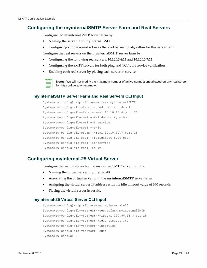
LSNAT Configuration Example
Configuring the myinternalSMTP Server Farm and Real ServersConfigure the myinternalSMTP server farm by:
• Naming the server farm myinternalSMTP
• Configuring simple round robin as the load balancing algorithm for this server farm
Configure the real servers on the myinternalSMTP server farm by:
• Configuring the following real servers: 10.10.10.6:25 and 10.10.10.7:25
• Configuring the SMTP servers for both ping and TCP port service verification
• Enabling each real server by placing each server in service
myinternalSMTP Server Farm and Real Servers CLI InputSystem(rw-config)->ip slb serverfarm myinternalSMTP
System(rw-config-slb-sfarm)->predictor roundrobin
System(rw-config-slb-sfarm)->real 10.10.10.6 port 25
System(rw-config-slb-real)->faildetect type both
System(rw-config-slb-real)->inservice
System(rw-config-slb-real)->exit
System(rw-config-slb-sfarm)->real 10.10.10.7 port 25
System(rw-config-slb-real)->faildetect type both
System(rw-config-slb-real)->inservice
System(rw-config-slb-real)->exit
Configuring myinternal-25 Virtual ServerConfigure the virtual server for the myinternalSMTP server farm by:
• Naming the virtual server myinternal‐25
• Associating the virtual server with the myinternalSMTP server farm
• Assigning the virtual server IP address with the idle timeout value of 360 seconds
• Placing the virtual server in service
myinternal-25 Virtual Server CLI InputSystem(rw-config)->ip slb vserver myinternal-25
System(rw-config-slb-vserver)->serverfarm myinternalSMTP
System(rw-config-slb-vserver)->virtual 194.56.13.3 tcp 25
System(rw-config-slb-vserver)->idle timeout 360
System(rw-config-slb-vserver)->inservice
System(rw-config-slb-vserver)->exit
System(rw-config)->
Notes: We will not modify the maximum number of active connections allowed on any real server for this configuration example.
September 8, 2010 Page 24 of 28
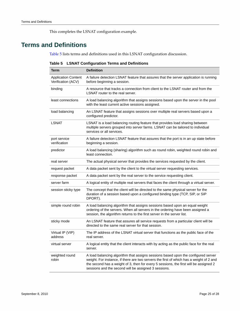
Terms and Definitions
This completes the LSNAT configuration example.
Terms and DefinitionsTable 5 lists terms and definitions used in this LSNAT configuration discussion.
Table 5 LSNAT Configuration Terms and Definitions Term Definition
Application Content Verification (ACV)
A failure detection LSNAT feature that assures that the server application is running before beginning a session.
binding A resource that tracks a connection from client to the LSNAT router and from the LSNAT router to the real server.
least connections A load balancing algorithm that assigns sessions based upon the server in the pool with the least current active sessions assigned.
load balancing An LSNAT feature that assigns sessions over multiple real servers based upon a configured predictor.
LSNAT LSNAT is a load balancing routing feature that provides load sharing between multiple servers grouped into server farms. LSNAT can be tailored to individual services or all services.
port service verification
A failure detection LSNAT feature that assures that the port is in an up state before beginning a session.
predictor A load balancing (sharing) algorithm such as round robin, weighted round robin and least connection.
real server The actual physical server that provides the services requested by the client.
request packet A data packet sent by the client to the virtual server requesting services.
response packet A data packet sent by the real server to the service requesting client.
server farm A logical entity of multiple real servers that faces the client through a virtual server.
session sticky type The concept that the client will be directed to the same physical server for the duration of a session based upon a configured binding type (TCP, SIP, or SIP DPORT).
simple round robin A load balancing algorithm that assigns sessions based upon an equal weight ordering of the servers. When all servers in the ordering have been assigned a session, the algorithm returns to the first server in the server list.
sticky mode An LSNAT feature that assures all service requests from a particular client will be directed to the same real server for that session.
Virtual IP (VIP) address
The IP address of the LSNAT virtual server that functions as the public face of the real server.
virtual server A logical entity that the client interacts with by acting as the public face for the real server.
weighted round robin
A load balancing algorithm that assigns sessions based upon the configured server weight. For instance, if there are two servers the first of which has a weight of 2 and the second has a weight of 3, then for every 5 sessions, the first will be assigned 2 sessions and the second will be assigned 3 sessions.
September 8, 2010 Page 25 of 28
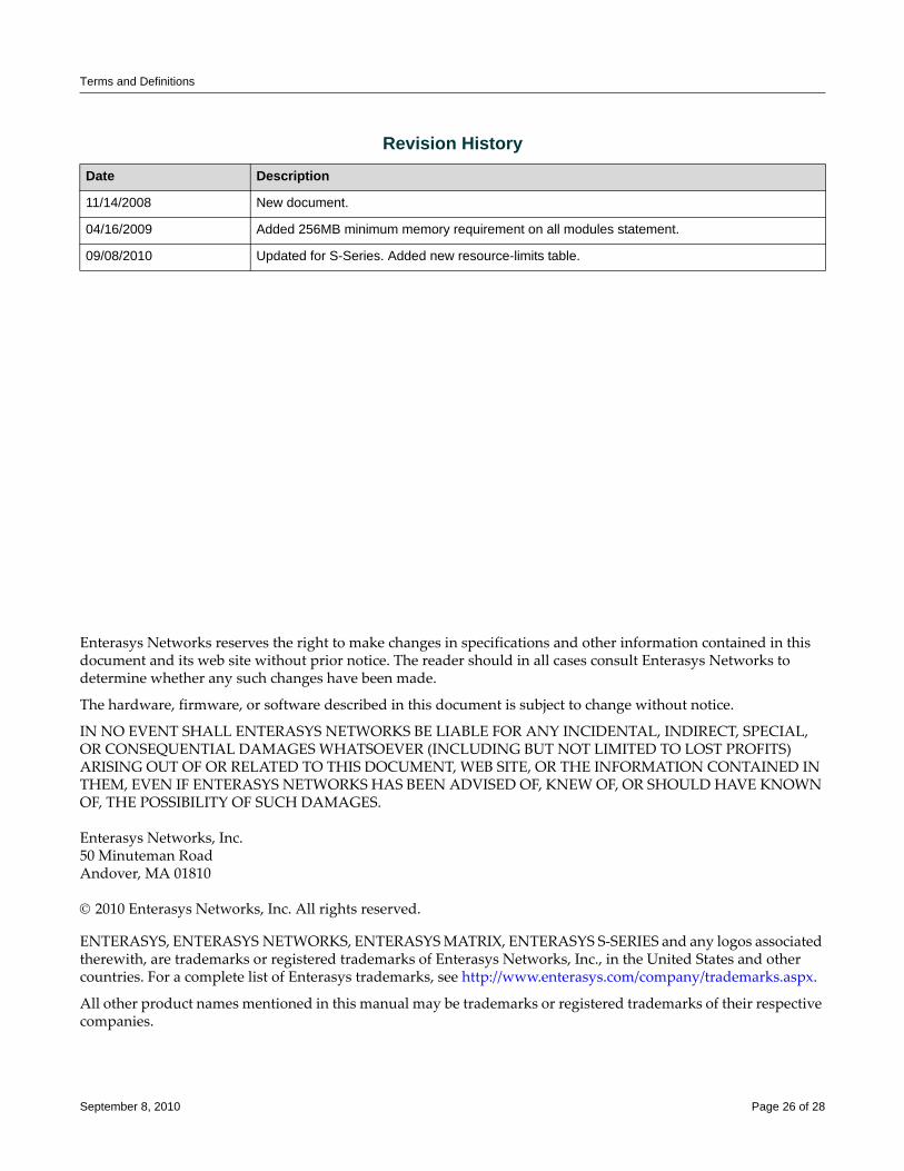
Terms and Definitions
Enterasys Networks reserves the right to make changes in specifications and other information contained in this document and its web site without prior notice. The reader should in all cases consult Enterasys Networks to determine whether any such changes have been made.
The hardware, firmware, or software described in this document is subject to change without notice.
IN NO EVENT SHALL ENTERASYS NETWORKS BE LIABLE FOR ANY INCIDENTAL, INDIRECT, SPECIAL, OR CONSEQUENTIAL DAMAGES WHATSOEVER (INCLUDING BUT NOT LIMITED TO LOST PROFITS) ARISING OUT OF OR RELATED TO THIS DOCUMENT, WEB SITE, OR THE INFORMATION CONTAINED IN THEM, EVEN IF ENTERASYS NETWORKS HAS BEEN ADVISED OF, KNEW OF, OR SHOULD HAVE KNOWN OF, THE POSSIBILITY OF SUCH DAMAGES.
Enterasys Networks, Inc.50 Minuteman RoadAndover, MA 01810
© 2010 Enterasys Networks, Inc. All rights reserved.
ENTERASYS, ENTERASYS NETWORKS, ENTERASYS MATRIX, ENTERASYS S‐SERIES and any logos associated therewith, are trademarks or registered trademarks of Enterasys Networks, Inc., in the United States and other countries. For a complete list of Enterasys trademarks, see http://www.enterasys.com/company/trademarks.aspx.
All other product names mentioned in this manual may be trademarks or registered trademarks of their respective companies.
Revision History
Date Description
11/14/2008 New document.
04/16/2009 Added 256MB minimum memory requirement on all modules statement.
09/08/2010 Updated for S-Series. Added new resource-limits table.
September 8, 2010 Page 26 of 28


Terms and Definitions
September 8, 2010 Page 28 of 28
Configuring Multicast
This document provides information about configuring and monitoring multicast on Enterasys Matrix® N‐Series, Enterasys SecureStack™, D‐Series, G‐Series, and I‐Series devices.
What Is Multicast?Multicast is a “one source to many destinations” method of simultaneously sending information over a network using the most efficient delivery strategy over each link. Only the end stations that explicitly indicate a need to receive a given multicast stream will receive it.
Applications that take advantage of multicast include video conferencing, streaming video, corporate communications, distance learning, and distribution of software, stock quotes, and news.
Multicast technology includes the following protocols:
• Internet Group Management Protocol (IGMP)
• Distance Vector Multicast Routing Protocol (DVMRP)
• Protocol Independent Multicast (PIM)
Why Would I Use Multicast in My Network?Unlike unicast and broadcast, multicast uses network infrastructure efficiently because only one copy of the source traffic is sent throughout the network, going only to interested receivers, minimizing the burden placed on the sender, network, and receiver. The routers in the network take care of replicating the packet, where necessary, to reach multiple receivers. If a router decides that there are no interested users downstream from itself, it prunes the stream back to the next router. Thus, unwanted streams are not sent to the pruned routers, saving bandwidth and preventing unwanted packets from being sent.
Note: For information on Enterasys Matrix X-Series support, refer to the Enterasys Matrix X Secure Core Router Configuration Guide.
For information about... Refer to page...
What Is Multicast? 1
Why Would I Use Multicast in My Network? 1
How Do I Implement Multicast? 2
Understanding Multicast 2
Configuring Multicast 15
April 16, 2009 Page 1 of 32
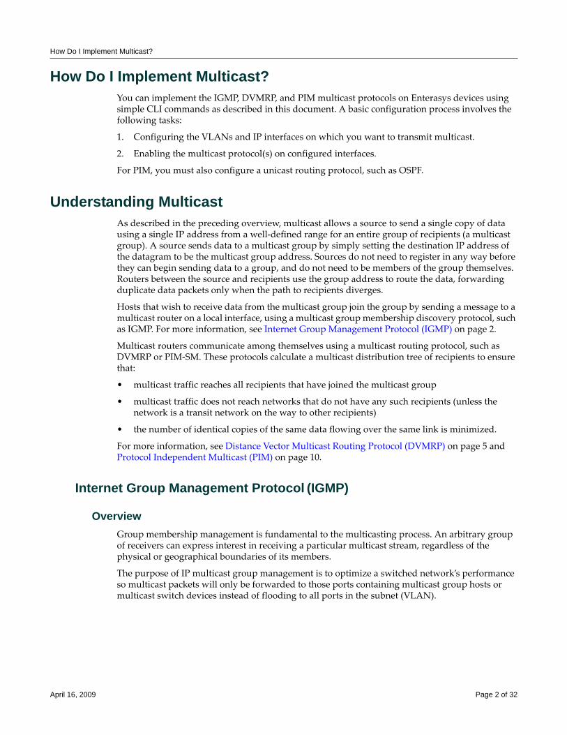
How Do I Implement Multicast?
How Do I Implement Multicast?You can implement the IGMP, DVMRP, and PIM multicast protocols on Enterasys devices using simple CLI commands as described in this document. A basic configuration process involves the following tasks:
1. Configuring the VLANs and IP interfaces on which you want to transmit multicast.
2. Enabling the multicast protocol(s) on configured interfaces.
For PIM, you must also configure a unicast routing protocol, such as OSPF.
Understanding Multicast As described in the preceding overview, multicast allows a source to send a single copy of data using a single IP address from a well‐defined range for an entire group of recipients (a multicast group). A source sends data to a multicast group by simply setting the destination IP address of the datagram to be the multicast group address. Sources do not need to register in any way before they can begin sending data to a group, and do not need to be members of the group themselves. Routers between the source and recipients use the group address to route the data, forwarding duplicate data packets only when the path to recipients diverges.
Hosts that wish to receive data from the multicast group join the group by sending a message to a multicast router on a local interface, using a multicast group membership discovery protocol, such as IGMP. For more information, see Internet Group Management Protocol (IGMP) on page 2.
Multicast routers communicate among themselves using a multicast routing protocol, such as DVMRP or PIM‐SM. These protocols calculate a multicast distribution tree of recipients to ensure that:
• multicast traffic reaches all recipients that have joined the multicast group
• multicast traffic does not reach networks that do not have any such recipients (unless the network is a transit network on the way to other recipients)
• the number of identical copies of the same data flowing over the same link is minimized.
For more information, see Distance Vector Multicast Routing Protocol (DVMRP) on page 5 and Protocol Independent Multicast (PIM) on page 10.
Internet Group Management Protocol (IGMP)
OverviewGroup membership management is fundamental to the multicasting process. An arbitrary group of receivers can express interest in receiving a particular multicast stream, regardless of the physical or geographical boundaries of its members.
The purpose of IP multicast group management is to optimize a switched network’s performance so multicast packets will only be forwarded to those ports containing multicast group hosts or multicast switch devices instead of flooding to all ports in the subnet (VLAN).
April 16, 2009 Page 2 of 32
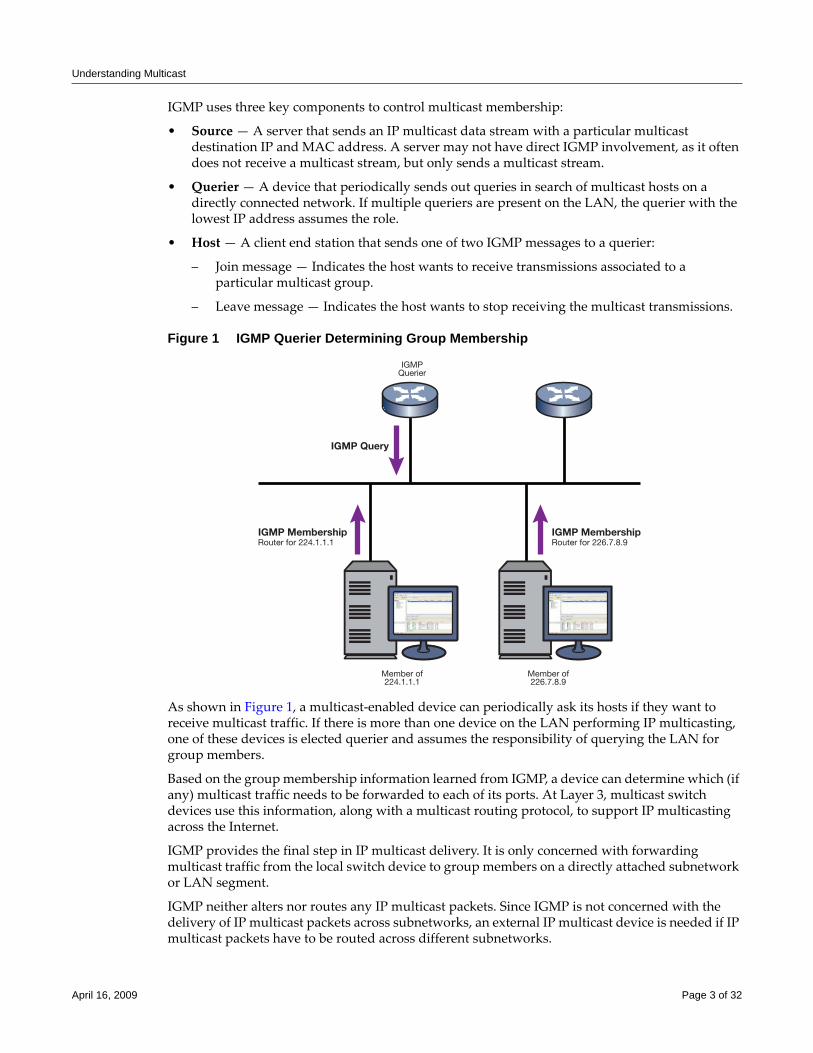
Understanding Multicast
IGMP uses three key components to control multicast membership:
• Source — A server that sends an IP multicast data stream with a particular multicast destination IP and MAC address. A server may not have direct IGMP involvement, as it often does not receive a multicast stream, but only sends a multicast stream.
• Querier — A device that periodically sends out queries in search of multicast hosts on a directly connected network. If multiple queriers are present on the LAN, the querier with the lowest IP address assumes the role.
• Host — A client end station that sends one of two IGMP messages to a querier:
– Join message — Indicates the host wants to receive transmissions associated to a particular multicast group.
– Leave message — Indicates the host wants to stop receiving the multicast transmissions.
Figure 1 IGMP Querier Determining Group Membership
As shown in Figure 1, a multicast‐enabled device can periodically ask its hosts if they want to receive multicast traffic. If there is more than one device on the LAN performing IP multicasting, one of these devices is elected querier and assumes the responsibility of querying the LAN for group members.
Based on the group membership information learned from IGMP, a device can determine which (if any) multicast traffic needs to be forwarded to each of its ports. At Layer 3, multicast switch devices use this information, along with a multicast routing protocol, to support IP multicasting across the Internet.
IGMP provides the final step in IP multicast delivery. It is only concerned with forwarding multicast traffic from the local switch device to group members on a directly attached subnetwork or LAN segment.
IGMP neither alters nor routes any IP multicast packets. Since IGMP is not concerned with the delivery of IP multicast packets across subnetworks, an external IP multicast device is needed if IP multicast packets have to be routed across different subnetworks.
IGMP Query
IGMPQuerier
Member of224.1.1.1
Member of226.7.8.9
IGMP MembershipRouter for 226.7.8.9
IGMP MembershipRouter for 224.1.1.1
April 16, 2009 Page 3 of 32
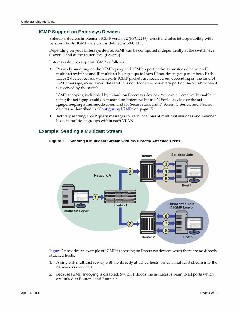
Understanding Multicast
IGMP Support on Enterasys DevicesEnterasys devices implement IGMP version 2 (RFC 2236), which includes interoperability with version 1 hosts. IGMP version 1 is defined in RFC 1112.
Depending on your Enterasys device, IGMP can be configured independently at the switch level (Layer 2) and at the router level (Layer 3).
Enterasys devices support IGMP as follows:
• Passively snooping on the IGMP query and IGMP report packets transferred between IP multicast switches and IP multicast host groups to learn IP multicast group members. Each Layer 2 device records which ports IGMP packets are received on, depending on the kind of IGMP message, so multicast data traffic is not flooded across every port on the VLAN when it is received by the switch.
IGMP snooping is disabled by default on Enterasys devices. You can automatically enable it using the set igmp enable command on Enterasys Matrix N‐Series devices or the set igmpsnooping adminmode command for SecureStack and D‐Series, G‐Series, and I‐Series devices as described in “Configuring IGMP” on page 15.
• Actively sending IGMP query messages to learn locations of multicast switches and member hosts in multicast groups within each VLAN.
Example: Sending a Multicast Stream
Figure 2 Sending a Multicast Stream with No Directly Attached Hosts
Figure 2 provides an example of IGMP processing on Enterasys devices when there are no directly attached hosts.
1. A single IP multicast server, with no directly attached hosts, sends a multicast stream into the network via Switch 1.
2. Because IGMP snooping is disabled, Switch 1 floods the multicast stream to all ports which are linked to Router 1 and Router 2.
2
3
4
5
1
2
Router 1
Host 1
Solicited Join
Network A
Unsolicited Join& IGMP Leave
Host 2
Multicast Server
Switch 1
Router 2
6
7
8
April 16, 2009 Page 4 of 32
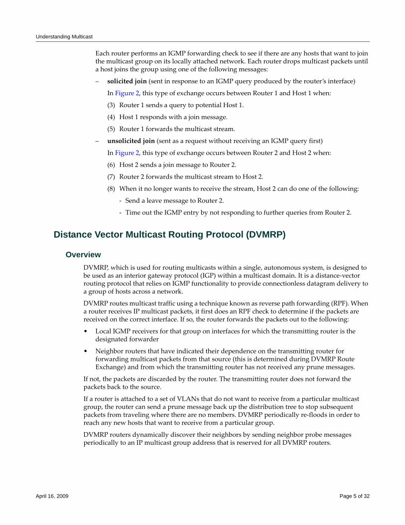
Understanding Multicast
Each router performs an IGMP forwarding check to see if there are any hosts that want to join the multicast group on its locally attached network. Each router drops multicast packets until a host joins the group using one of the following messages:
– solicited join (sent in response to an IGMP query produced by the router’s interface)
In Figure 2, this type of exchange occurs between Router 1 and Host 1 when:
(3) Router 1 sends a query to potential Host 1.
(4) Host 1 responds with a join message.
(5) Router 1 forwards the multicast stream.
– unsolicited join (sent as a request without receiving an IGMP query first)
In Figure 2, this type of exchange occurs between Router 2 and Host 2 when:
(6) Host 2 sends a join message to Router 2.
(7) Router 2 forwards the multicast stream to Host 2.
(8) When it no longer wants to receive the stream, Host 2 can do one of the following:
‐ Send a leave message to Router 2.
‐ Time out the IGMP entry by not responding to further queries from Router 2.
Distance Vector Multicast Routing Protocol (DVMRP)
OverviewDVMRP, which is used for routing multicasts within a single, autonomous system, is designed to be used as an interior gateway protocol (IGP) within a multicast domain. It is a distance‐vector routing protocol that relies on IGMP functionality to provide connectionless datagram delivery to a group of hosts across a network.
DVMRP routes multicast traffic using a technique known as reverse path forwarding (RPF). When a router receives IP multicast packets, it first does an RPF check to determine if the packets are received on the correct interface. If so, the router forwards the packets out to the following:
• Local IGMP receivers for that group on interfaces for which the transmitting router is the designated forwarder
• Neighbor routers that have indicated their dependence on the transmitting router for forwarding multicast packets from that source (this is determined during DVMRP Route Exchange) and from which the transmitting router has not received any prune messages.
If not, the packets are discarded by the router. The transmitting router does not forward the packets back to the source.
If a router is attached to a set of VLANs that do not want to receive from a particular multicast group, the router can send a prune message back up the distribution tree to stop subsequent packets from traveling where there are no members. DVMRP periodically re‐floods in order to reach any new hosts that want to receive from a particular group.
DVMRP routers dynamically discover their neighbors by sending neighbor probe messages periodically to an IP multicast group address that is reserved for all DVMRP routers.
April 16, 2009 Page 5 of 32
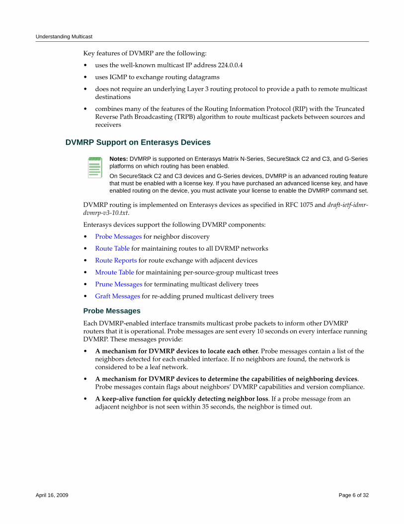
Understanding Multicast
Key features of DVMRP are the following:
• uses the well‐known multicast IP address 224.0.0.4
• uses IGMP to exchange routing datagrams
• does not require an underlying Layer 3 routing protocol to provide a path to remote multicast destinations
• combines many of the features of the Routing Information Protocol (RIP) with the Truncated Reverse Path Broadcasting (TRPB) algorithm to route multicast packets between sources and receivers
DVMRP Support on Enterasys Devices
DVMRP routing is implemented on Enterasys devices as specified in RFC 1075 and draft‐ietf‐idmr‐dvmrp‐v3‐10.txt.
Enterasys devices support the following DVMRP components:
• Probe Messages for neighbor discovery
• Route Table for maintaining routes to all DVRMP networks
• Route Reports for route exchange with adjacent devices
• Mroute Table for maintaining per‐source‐group multicast trees
• Prune Messages for terminating multicast delivery trees
• Graft Messages for re‐adding pruned multicast delivery trees
Probe MessagesEach DVMRP‐enabled interface transmits multicast probe packets to inform other DVMRP routers that it is operational. Probe messages are sent every 10 seconds on every interface running DVMRP. These messages provide:
• A mechanism for DVMRP devices to locate each other. Probe messages contain a list of the neighbors detected for each enabled interface. If no neighbors are found, the network is considered to be a leaf network.
• A mechanism for DVMRP devices to determine the capabilities of neighboring devices. Probe messages contain flags about neighbors’ DVMRP capabilities and version compliance.
• A keep‐alive function for quickly detecting neighbor loss. If a probe message from an adjacent neighbor is not seen within 35 seconds, the neighbor is timed out.
Notes: DVMRP is supported on Enterasys Matrix N-Series, SecureStack C2 and C3, and G-Series platforms on which routing has been enabled.
On SecureStack C2 and C3 devices and G-Series devices, DVMRP is an advanced routing feature that must be enabled with a license key. If you have purchased an advanced license key, and have enabled routing on the device, you must activate your license to enable the DVMRP command set.
April 16, 2009 Page 6 of 32
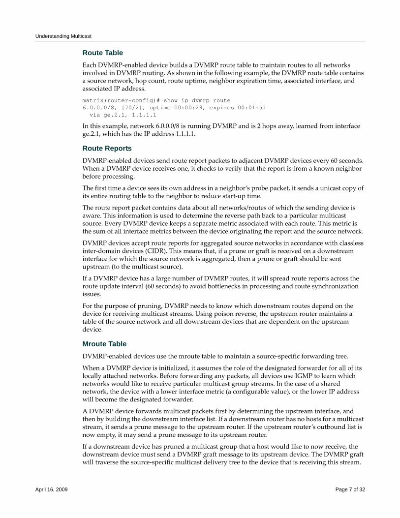
Understanding Multicast
Route TableEach DVMRP‐enabled device builds a DVMRP route table to maintain routes to all networks involved in DVMRP routing. As shown in the following example, the DVMRP route table contains a source network, hop count, route uptime, neighbor expiration time, associated interface, and associated IP address.
matrix(router-config)# show ip dvmrp route6.0.0.0/8, [70/2], uptime 00:00:29, expires 00:01:51 via ge.2.1, 1.1.1.1
In this example, network 6.0.0.0/8 is running DVMRP and is 2 hops away, learned from interface ge.2.1, which has the IP address 1.1.1.1.
Route ReportsDVMRP‐enabled devices send route report packets to adjacent DVMRP devices every 60 seconds. When a DVMRP device receives one, it checks to verify that the report is from a known neighbor before processing.
The first time a device sees its own address in a neighbor’s probe packet, it sends a unicast copy of its entire routing table to the neighbor to reduce start‐up time.
The route report packet contains data about all networks/routes of which the sending device is aware. This information is used to determine the reverse path back to a particular multicast source. Every DVMRP device keeps a separate metric associated with each route. This metric is the sum of all interface metrics between the device originating the report and the source network.
DVMRP devices accept route reports for aggregated source networks in accordance with classless inter‐domain devices (CIDR). This means that, if a prune or graft is received on a downstream interface for which the source network is aggregated, then a prune or graft should be sent upstream (to the multicast source).
If a DVMRP device has a large number of DVMRP routes, it will spread route reports across the route update interval (60 seconds) to avoid bottlenecks in processing and route synchronization issues.
For the purpose of pruning, DVMRP needs to know which downstream routes depend on the device for receiving multicast streams. Using poison reverse, the upstream router maintains a table of the source network and all downstream devices that are dependent on the upstream device.
Mroute TableDVMRP‐enabled devices use the mroute table to maintain a source‐specific forwarding tree.
When a DVMRP device is initialized, it assumes the role of the designated forwarder for all of its locally attached networks. Before forwarding any packets, all devices use IGMP to learn which networks would like to receive particular multicast group streams. In the case of a shared network, the device with a lower interface metric (a configurable value), or the lower IP address will become the designated forwarder.
A DVMRP device forwards multicast packets first by determining the upstream interface, and then by building the downstream interface list. If a downstream router has no hosts for a multicast stream, it sends a prune message to the upstream router. If the upstream router’s outbound list is now empty, it may send a prune message to its upstream router.
If a downstream device has pruned a multicast group that a host would like to now receive, the downstream device must send a DVMRP graft message to its upstream device. The DVMRP graft will traverse the source‐specific multicast delivery tree to the device that is receiving this stream.
April 16, 2009 Page 7 of 32
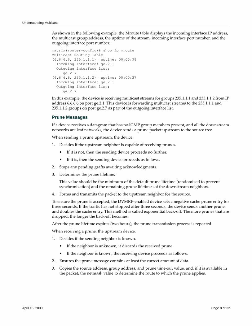
Understanding Multicast
As shown in the following example, the Mroute table displays the incoming interface IP address, the multicast group address, the uptime of the stream, incoming interface port number, and the outgoing interface port number.
matrix(router-config)# show ip mrouteMulticast Routing Table(6.6.6.6, 235.1.1.1), uptime: 00:00:38 Incoming interface: ge.2.1 Outgoing interface list: ge.2.7(6.6.6.6, 235.1.1.2), uptime: 00:00:37 Incoming interface: ge.2.1 Outgoing interface list: ge.2.7
In this example, the device is receiving multicast streams for groups 235.1.1.1 and 235.1.1.2 from IP address 6.6.6.6 on port ge.2.1. This device is forwarding multicast streams to the 235.1.1.1 and 235.1.1.2 groups on port ge.2.7 as part of the outgoing interface list.
Prune MessagesIf a device receives a datagram that has no IGMP group members present, and all the downstream networks are leaf networks, the device sends a prune packet upstream to the source tree.
When sending a prune upstream, the device:
1. Decides if the upstream neighbor is capable of receiving prunes.
• If it is not, then the sending device proceeds no further.
• If it is, then the sending device proceeds as follows.
2. Stops any pending grafts awaiting acknowledgments.
3. Determines the prune lifetime.
This value should be the minimum of the default prune lifetime (randomized to prevent synchronization) and the remaining prune lifetimes of the downstream neighbors.
4. Forms and transmits the packet to the upstream neighbor for the source.
To ensure the prune is accepted, the DVMRP‐enabled device sets a negative cache prune entry for three seconds. If the traffic has not stopped after three seconds, the device sends another prune and doubles the cache entry. This method is called exponential back‐off. The more prunes that are dropped, the longer the back‐off becomes.
After the prune lifetime expires (two hours), the prune transmission process is repeated.
When receiving a prune, the upstream device:
1. Decides if the sending neighbor is known.
• If the neighbor is unknown, it discards the received prune.
• If the neighbor is known, the receiving device proceeds as follows.
2. Ensures the prune message contains at least the correct amount of data.
3. Copies the source address, group address, and prune time‐out value, and, if it is available in the packet, the netmask value to determine the route to which the prune applies.
April 16, 2009 Page 8 of 32

Understanding Multicast
4. Determines if there is active source information for the source network, multicast group (S,G) pair.
• If there is not, then the device ignores the prune.
• If there is, then the device proceeds as follows.
5. Verifies that the prune was received from a dependent neighbor for the source network.
• If it was not, then the device discards the prune.
• If it was, then the device proceeds as follows.
6. Determines if a prune is currently active from the same dependent neighbor for this S,G pair.
• If not active, creates a state for the new prune and sets a timer for the prune lifetime
• If active, resets the timer to the new time‐out value.
7. Determines if all dependent downstream devices on the interface from which the prune was received have now sent prunes.
• If they have not, removes the interface from all forwarding cache entries for this group instantiated using the route to which the prune applies.
• If they have, determines if there are group members active on the interface and if this device is the designated forwarder for the network.
Graft Messages Leaf devices send graft messages when the following occur:
• A new local member joins a group that has been pruned upstream and this device is the designated forwarder for the source.
• A new dependent downstream device appears on a pruned branch.
• A dependent downstream device on a pruned branch restarts.
• A graft retransmission timer expires before a graft ACK is received.
Graft messages are sent upstream hop‐by‐hop until the multicast tree is reached. Since there is no way to tell whether a graft message was lost or the source has stopped sending, each graft message is acknowledged hop‐by‐hop.
When sending grafts, the downstream device does the following:
1. Verifies a prune exists for the source network and group.
2. Verifies that the upstream device is capable of receiving prunes (and therefore grafts).
3. Adds the graft to the retransmission timer list awaiting an acknowledgment.
4. Formulates and transmits the graft packet.
When receiving grafts, the upstream device does the following:
1. Verifies whether the neighbor is known.
• If unknown, discards the received graft.
• If known, proceeds as follows.
2. Ensures the graft message contains at least the correct amount of data.
3. Sends back a graft ACK to the sender.
April 16, 2009 Page 9 of 32
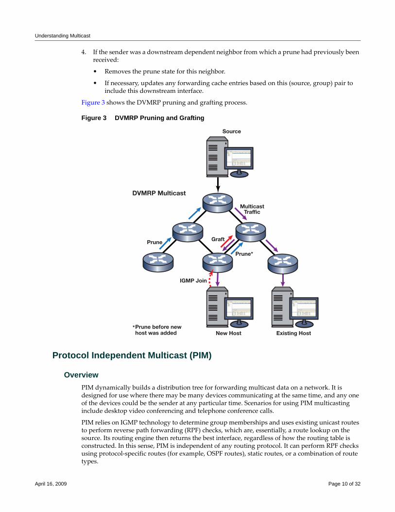
Understanding Multicast
4. If the sender was a downstream dependent neighbor from which a prune had previously been received:
• Removes the prune state for this neighbor.
• If necessary, updates any forwarding cache entries based on this (source, group) pair to include this downstream interface.
Figure 3 shows the DVMRP pruning and grafting process.
Figure 3 DVMRP Pruning and Grafting
Protocol Independent Multicast (PIM)
OverviewPIM dynamically builds a distribution tree for forwarding multicast data on a network. It is designed for use where there may be many devices communicating at the same time, and any one of the devices could be the sender at any particular time. Scenarios for using PIM multicasting include desktop video conferencing and telephone conference calls.
PIM relies on IGMP technology to determine group memberships and uses existing unicast routes to perform reverse path forwarding (RPF) checks, which are, essentially, a route lookup on the source. Its routing engine then returns the best interface, regardless of how the routing table is constructed. In this sense, PIM is independent of any routing protocol. It can perform RPF checks using protocol‐specific routes (for example, OSPF routes), static routes, or a combination of route types.
MulticastTraffic
Prune*
Prune Graft
IGMP Join
Source
New Host
DVMRP Multicast
Existing HostPrune before newhost was added
*
April 16, 2009 Page 10 of 32
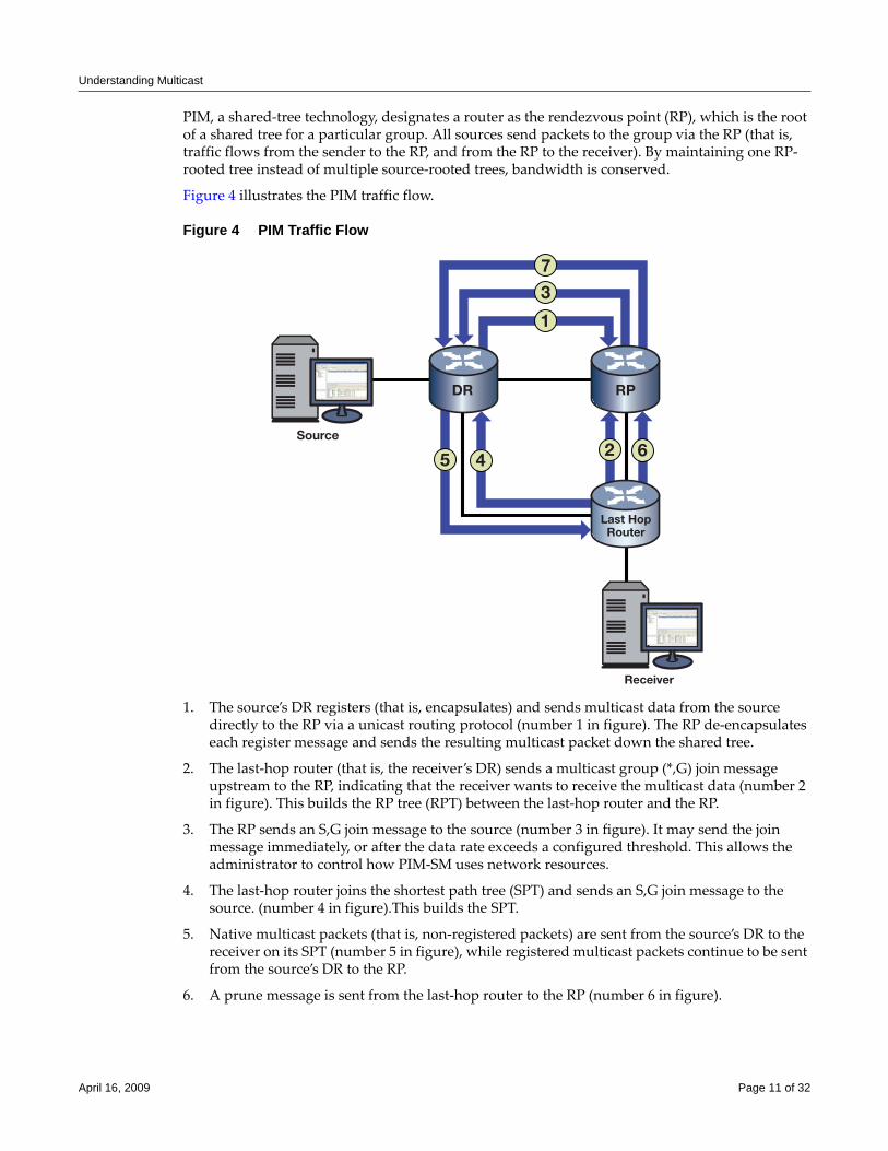
Understanding Multicast
PIM, a shared‐tree technology, designates a router as the rendezvous point (RP), which is the root of a shared tree for a particular group. All sources send packets to the group via the RP (that is, traffic flows from the sender to the RP, and from the RP to the receiver). By maintaining one RP‐rooted tree instead of multiple source‐rooted trees, bandwidth is conserved.
Figure 4 illustrates the PIM traffic flow.
Figure 4 PIM Traffic Flow
1. The source’s DR registers (that is, encapsulates) and sends multicast data from the source directly to the RP via a unicast routing protocol (number 1 in figure). The RP de‐encapsulates each register message and sends the resulting multicast packet down the shared tree.
2. The last‐hop router (that is, the receiver’s DR) sends a multicast group (*,G) join message upstream to the RP, indicating that the receiver wants to receive the multicast data (number 2 in figure). This builds the RP tree (RPT) between the last‐hop router and the RP.
3. The RP sends an S,G join message to the source (number 3 in figure). It may send the join message immediately, or after the data rate exceeds a configured threshold. This allows the administrator to control how PIM‐SM uses network resources.
4. The last‐hop router joins the shortest path tree (SPT) and sends an S,G join message to the source. (number 4 in figure).This builds the SPT.
5. Native multicast packets (that is, non‐registered packets) are sent from the source’s DR to the receiver on its SPT (number 5 in figure), while registered multicast packets continue to be sent from the source’s DR to the RP.
6. A prune message is sent from the last‐hop router to the RP (number 6 in figure).
3
45 6
1
2Source
Receiver
7
DR RP
Last HopRouter
April 16, 2009 Page 11 of 32
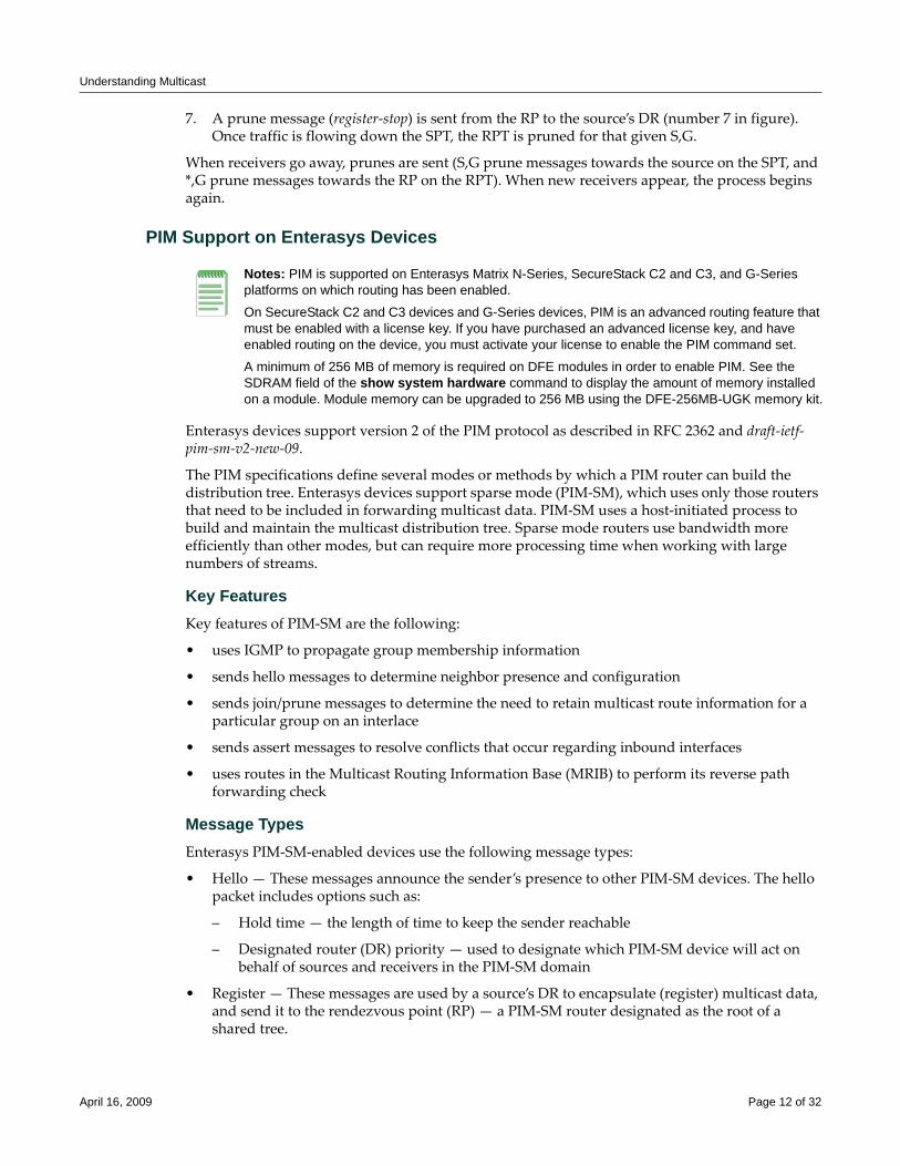
Understanding Multicast
7. A prune message (register‐stop) is sent from the RP to the source’s DR (number 7 in figure). Once traffic is flowing down the SPT, the RPT is pruned for that given S,G.
When receivers go away, prunes are sent (S,G prune messages towards the source on the SPT, and *,G prune messages towards the RP on the RPT). When new receivers appear, the process begins again.
PIM Support on Enterasys Devices
Enterasys devices support version 2 of the PIM protocol as described in RFC 2362 and draft‐ietf‐pim‐sm‐v2‐new‐09.
The PIM specifications define several modes or methods by which a PIM router can build the distribution tree. Enterasys devices support sparse mode (PIM‐SM), which uses only those routers that need to be included in forwarding multicast data. PIM‐SM uses a host‐initiated process to build and maintain the multicast distribution tree. Sparse mode routers use bandwidth more efficiently than other modes, but can require more processing time when working with large numbers of streams.
Key FeaturesKey features of PIM‐SM are the following:
• uses IGMP to propagate group membership information
• sends hello messages to determine neighbor presence and configuration
• sends join/prune messages to determine the need to retain multicast route information for a particular group on an interlace
• sends assert messages to resolve conflicts that occur regarding inbound interfaces
• uses routes in the Multicast Routing Information Base (MRIB) to perform its reverse path forwarding check
Message TypesEnterasys PIM‐SM‐enabled devices use the following message types:
• Hello — These messages announce the sender’s presence to other PIM‐SM devices. The hello packet includes options such as:
– Hold time — the length of time to keep the sender reachable
– Designated router (DR) priority — used to designate which PIM‐SM device will act on behalf of sources and receivers in the PIM‐SM domain
• Register — These messages are used by a source’s DR to encapsulate (register) multicast data, and send it to the rendezvous point (RP) — a PIM‐SM router designated as the root of a shared tree.
Notes: PIM is supported on Enterasys Matrix N-Series, SecureStack C2 and C3, and G-Series platforms on which routing has been enabled.
On SecureStack C2 and C3 devices and G-Series devices, PIM is an advanced routing feature that must be enabled with a license key. If you have purchased an advanced license key, and have enabled routing on the device, you must activate your license to enable the PIM command set.
A minimum of 256 MB of memory is required on DFE modules in order to enable PIM. See the SDRAM field of the show system hardware command to display the amount of memory installed on a module. Module memory can be upgraded to 256 MB using the DFE-256MB-UGK memory kit.
April 16, 2009 Page 12 of 32
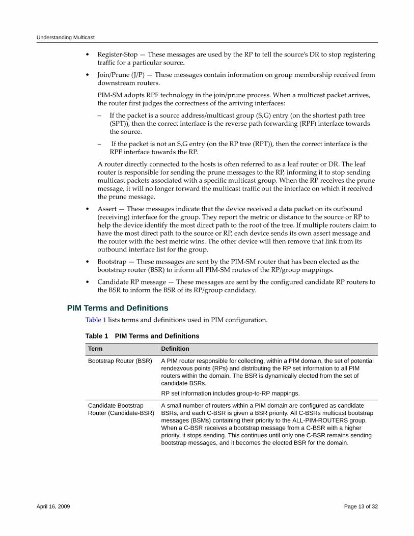
Understanding Multicast
• Register‐Stop — These messages are used by the RP to tell the source’s DR to stop registering traffic for a particular source.
• Join/Prune (J/P) — These messages contain information on group membership received from downstream routers.
PIM‐SM adopts RPF technology in the join/prune process. When a multicast packet arrives, the router first judges the correctness of the arriving interfaces:
– If the packet is a source address/multicast group (S,G) entry (on the shortest path tree (SPT)), then the correct interface is the reverse path forwarding (RPF) interface towards the source.
– If the packet is not an S,G entry (on the RP tree (RPT)), then the correct interface is the RPF interface towards the RP.
A router directly connected to the hosts is often referred to as a leaf router or DR. The leaf router is responsible for sending the prune messages to the RP, informing it to stop sending multicast packets associated with a specific multicast group. When the RP receives the prune message, it will no longer forward the multicast traffic out the interface on which it received the prune message.
• Assert — These messages indicate that the device received a data packet on its outbound (receiving) interface for the group. They report the metric or distance to the source or RP to help the device identify the most direct path to the root of the tree. If multiple routers claim to have the most direct path to the source or RP, each device sends its own assert message and the router with the best metric wins. The other device will then remove that link from its outbound interface list for the group.
• Bootstrap — These messages are sent by the PIM‐SM router that has been elected as the bootstrap router (BSR) to inform all PIM‐SM routes of the RP/group mappings.
• Candidate RP message — These messages are sent by the configured candidate RP routers to the BSR to inform the BSR of its RP/group candidacy.
PIM Terms and DefinitionsTable 1 lists terms and definitions used in PIM configuration.
Table 1 PIM Terms and Definitions
Term Definition
Bootstrap Router (BSR) A PIM router responsible for collecting, within a PIM domain, the set of potential rendezvous points (RPs) and distributing the RP set information to all PIM routers within the domain. The BSR is dynamically elected from the set of candidate BSRs.
RP set information includes group-to-RP mappings.
Candidate Bootstrap Router (Candidate-BSR)
A small number of routers within a PIM domain are configured as candidate BSRs, and each C-BSR is given a BSR priority. All C-BSRs multicast bootstrap messages (BSMs) containing their priority to the ALL-PIM-ROUTERS group. When a C-BSR receives a bootstrap message from a C-BSR with a higher priority, it stops sending. This continues until only one C-BSR remains sending bootstrap messages, and it becomes the elected BSR for the domain.
April 16, 2009 Page 13 of 32
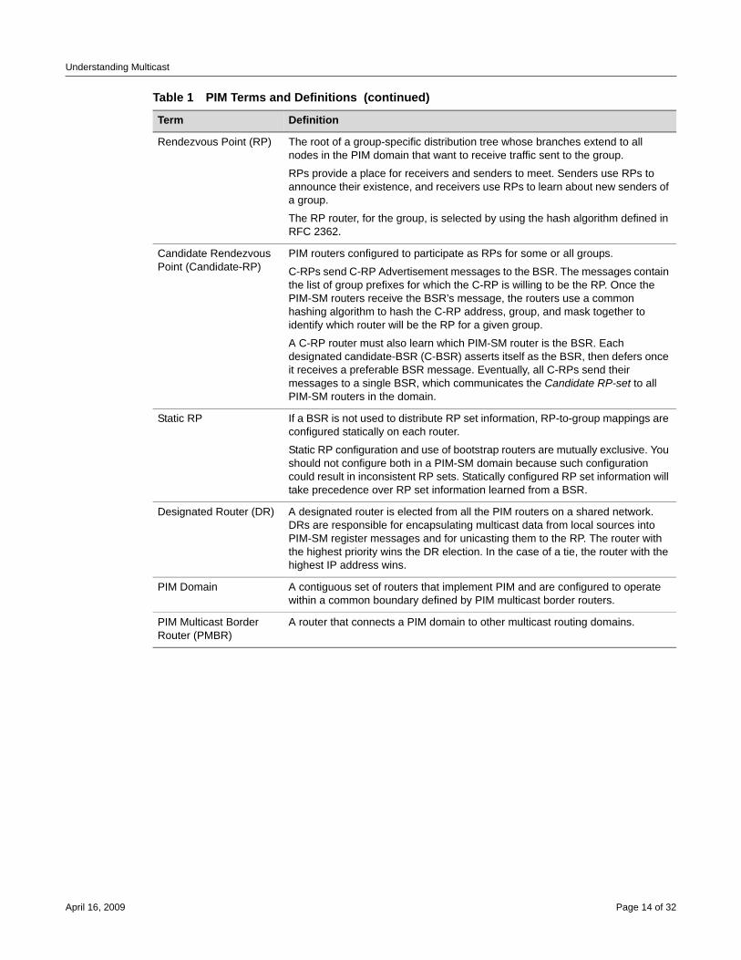
Understanding Multicast
Rendezvous Point (RP) The root of a group-specific distribution tree whose branches extend to all nodes in the PIM domain that want to receive traffic sent to the group.
RPs provide a place for receivers and senders to meet. Senders use RPs to announce their existence, and receivers use RPs to learn about new senders of a group.
The RP router, for the group, is selected by using the hash algorithm defined in RFC 2362.
Candidate Rendezvous Point (Candidate-RP)
PIM routers configured to participate as RPs for some or all groups.
C-RPs send C-RP Advertisement messages to the BSR. The messages contain the list of group prefixes for which the C-RP is willing to be the RP. Once the PIM-SM routers receive the BSR’s message, the routers use a common hashing algorithm to hash the C-RP address, group, and mask together to identify which router will be the RP for a given group.
A C-RP router must also learn which PIM-SM router is the BSR. Each designated candidate-BSR (C-BSR) asserts itself as the BSR, then defers once it receives a preferable BSR message. Eventually, all C-RPs send their messages to a single BSR, which communicates the Candidate RP-set to all PIM-SM routers in the domain.
Static RP If a BSR is not used to distribute RP set information, RP-to-group mappings are configured statically on each router.
Static RP configuration and use of bootstrap routers are mutually exclusive. You should not configure both in a PIM-SM domain because such configuration could result in inconsistent RP sets. Statically configured RP set information will take precedence over RP set information learned from a BSR.
Designated Router (DR) A designated router is elected from all the PIM routers on a shared network. DRs are responsible for encapsulating multicast data from local sources into PIM-SM register messages and for unicasting them to the RP. The router with the highest priority wins the DR election. In the case of a tie, the router with the highest IP address wins.
PIM Domain A contiguous set of routers that implement PIM and are configured to operate within a common boundary defined by PIM multicast border routers.
PIM Multicast Border Router (PMBR)
A router that connects a PIM domain to other multicast routing domains.
Table 1 PIM Terms and Definitions (continued)
Term Definition
April 16, 2009 Page 14 of 32
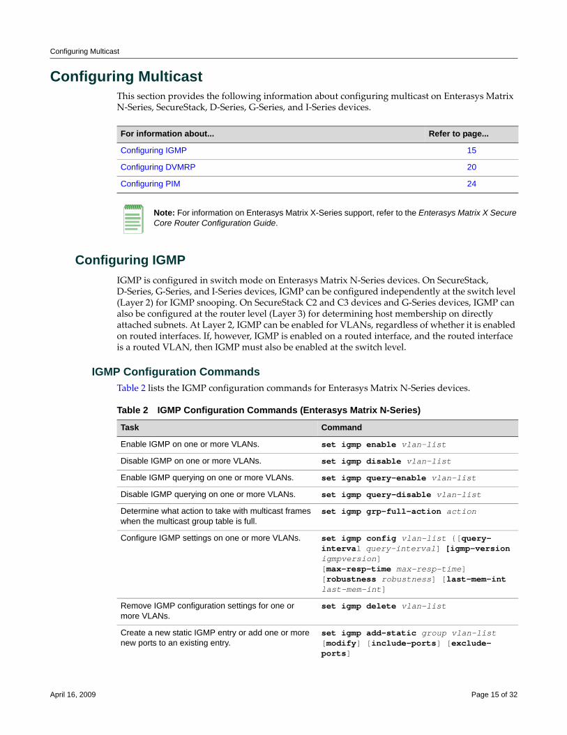
Configuring Multicast
Configuring MulticastThis section provides the following information about configuring multicast on Enterasys Matrix N‐Series, SecureStack, D‐Series, G‐Series, and I‐Series devices.
Configuring IGMPIGMP is configured in switch mode on Enterasys Matrix N‐Series devices. On SecureStack, D‐Series, G‐Series, and I‐Series devices, IGMP can be configured independently at the switch level (Layer 2) for IGMP snooping. On SecureStack C2 and C3 devices and G‐Series devices, IGMP can also be configured at the router level (Layer 3) for determining host membership on directly attached subnets. At Layer 2, IGMP can be enabled for VLANs, regardless of whether it is enabled on routed interfaces. If, however, IGMP is enabled on a routed interface, and the routed interface is a routed VLAN, then IGMP must also be enabled at the switch level.
IGMP Configuration CommandsTable 2 lists the IGMP configuration commands for Enterasys Matrix N‐Series devices.
For information about... Refer to page...
Configuring IGMP 15
Configuring DVMRP 20
Configuring PIM 24
Note: For information on Enterasys Matrix X-Series support, refer to the Enterasys Matrix X Secure Core Router Configuration Guide.
Table 2 IGMP Configuration Commands (Enterasys Matrix N-Series)
Task Command
Enable IGMP on one or more VLANs. set igmp enable vlan-list
Disable IGMP on one or more VLANs. set igmp disable vlan-list
Enable IGMP querying on one or more VLANs. set igmp query-enable vlan-list
Disable IGMP querying on one or more VLANs. set igmp query-disable vlan-list
Determine what action to take with multicast frames when the multicast group table is full.
set igmp grp-full-action action
Configure IGMP settings on one or more VLANs. set igmp config vlan-list {[query-interval query-interval] [igmp-version igmpversion][max-resp-time max-resp-time] [robustness robustness] [last-mem-int last-mem-int]
Remove IGMP configuration settings for one or more VLANs.
set igmp delete vlan-list
Create a new static IGMP entry or add one or more new ports to an existing entry.
set igmp add-static group vlan-list [modify] [include-ports] [exclude-ports]
April 16, 2009 Page 15 of 32
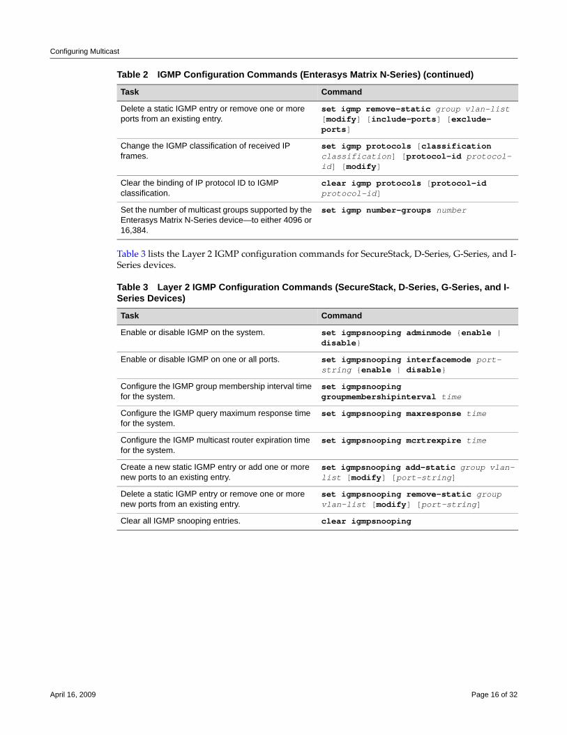
Configuring Multicast
Table 3 lists the Layer 2 IGMP configuration commands for SecureStack, D‐Series, G‐Series, and I‐Series devices.
Delete a static IGMP entry or remove one or more ports from an existing entry.
set igmp remove-static group vlan-list [modify] [include-ports] [exclude-ports]
Change the IGMP classification of received IP frames.
set igmp protocols [classification classification] [protocol-id protocol-id] [modify]
Clear the binding of IP protocol ID to IGMP classification.
clear igmp protocols [protocol-id protocol-id]
Set the number of multicast groups supported by the Enterasys Matrix N-Series device—to either 4096 or 16,384.
set igmp number-groups number
Table 3 Layer 2 IGMP Configuration Commands (SecureStack, D-Series, G-Series, and I-Series Devices)
Task Command
Enable or disable IGMP on the system. set igmpsnooping adminmode {enable | disable}
Enable or disable IGMP on one or all ports. set igmpsnooping interfacemode port-string {enable | disable}
Configure the IGMP group membership interval time for the system.
set igmpsnooping groupmembershipinterval time
Configure the IGMP query maximum response time for the system.
set igmpsnooping maxresponse time
Configure the IGMP multicast router expiration time for the system.
set igmpsnooping mcrtrexpire time
Create a new static IGMP entry or add one or more new ports to an existing entry.
set igmpsnooping add-static group vlan-list [modify] [port-string]
Delete a static IGMP entry or remove one or more new ports from an existing entry.
set igmpsnooping remove-static group vlan-list [modify] [port-string]
Clear all IGMP snooping entries. clear igmpsnooping
Table 2 IGMP Configuration Commands (Enterasys Matrix N-Series) (continued)
Task Command
April 16, 2009 Page 16 of 32
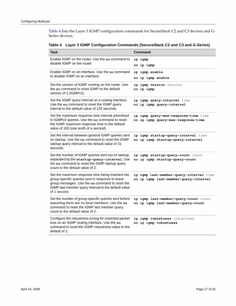
Configuring Multicast
Table 4 lists the Layer 3 IGMP configuration commands for SecureStack C2 and C3 devices and G‐Series devices.
Table 4 Layer 3 IGMP Configuration Commands (SecureStack C2 and C3 and G-Series)
Task Command
Enable IGMP on the router. Use the no command to disable IGMP on the router.
ip igmp
no ip igmp
Enable IGMP on an interface. Use the no command to disable IGMP on an interface.
ip igmp enable
no ip igmp enable
Set the version of IGMP running on the router. Use the no command to reset IGMP to the default version of 2 (IGMPv2).
ip igmp version versionno ip igmp
Set the IGMP query interval on a routing interface. Use the no command to reset the IGMP query interval to the default value of 125 seconds.
ip igmp query-interval timeno ip igmp query-interval
Set the maximum response time interval advertised in IGMPv2 queries. Use the no command to reset the IGMP maximum response time to the default value of 100 (one tenth of a second).
ip igmp query-max-response-time timeno ip igmp query-max-response-time
Set the interval between general IGMP queries sent on startup. Use the no command to reset the IGMP startup query interval to the default value of 31 seconds.
ip igmp startup-query-interval timeno ip igmp startup-query-interval
Set the number of IGMP queries sent out on startup, separated by the startup-query-interval. Use the no command to reset the IGMP startup query count to the default value of 2.
ip igmp startup-query-count countno ip igmp startup-query-count
Set the maximum response time being inserted into group-specific queries sent in response to leave group messages. Use the no command to reset the IGMP last member query interval to the default value of 1 second.
ip igmp last-member-query-interval timeno ip igmp last-member-query-interval
Set the number of group-specific queries sent before assuming there are no local members. Use the no command to reset the IGMP last member query count to the default value of 2.
ip igmp last-member-query-count countno ip igmp last-member-query-count
Configure the robustness tuning for expected packet loss on an IGMP routing interface. Use the no command to reset the IGMP robustness value to the default of 2.
ip igmp robustness robustnessno ip igmp robustness
April 16, 2009 Page 17 of 32
Configuring Multicast
Basic IGMP Configurations
Procedure 1 describes the basic steps to configure IGMP on Enterasys Matrix N‐Series devices. This procedure assumes that the VLANs on which IGMP will run have been configured and enabled with IP interfaces.
Procedure 2 describes the basic steps to configure Layer 2 IGMP snooping on SecureStack, D‐Series, G‐Series, and I‐Series devices. This procedure assumes that the VLANs on which IGMP will run have been configured and enabled with IP interfaces.
Procedure 3 describes the basic steps to configure Layer 3 IGMP querying on SecureStack C2 and C3 devices and G‐Series devices. This procedure assumes that the VLANs on which IGMP will run have been configured and enabled with IP interfaces.
For more information on IGMP CLI commands, refer to your device’s CLI Reference Guide or Configuration Guide, as applicable.
Procedure 1 Basic IGMP Configuration (Enterasys Matrix N-Series)
Step Task Command
1. In switch mode, configure IGMP for each VLAN interface.
set igmp config vlan-list {[query-interval query-interval] [igmp-version igmpversion][max-resp-time max-resp-time] [robustness robustness] [last-mem-int last-mem-int]}
2. In switch mode, enable IGMP on each VLAN interface.
set igmp enable vlan-list
3. In switch mode, enable IGMP querying on each of the VLANs specified in step 2.
set igmp query-enable vlan-list
Procedure 2 Basic IGMP Configuration (SecureStack, D-Series, G-Series, and I-Series)
Step Task Command
1. In switch mode, enable IGMP globally. set igmpsnooping adminmode enable
2. In switch mode, enable IGMP on each of the VLAN ports.
set igmpsnooping interfacemode port-string enable
Procedure 3 Basic IGMP Configuration (SecureStack C2 and C3 and G-Series)
Step Task Command
1. In router configuration mode, enable IGMP globally. ip igmp
2. In router configuration mode, enable IGMP on each VLAN interface that will be required to determine host membership on directly attached subnets.
ip igmp enable
April 16, 2009 Page 18 of 32
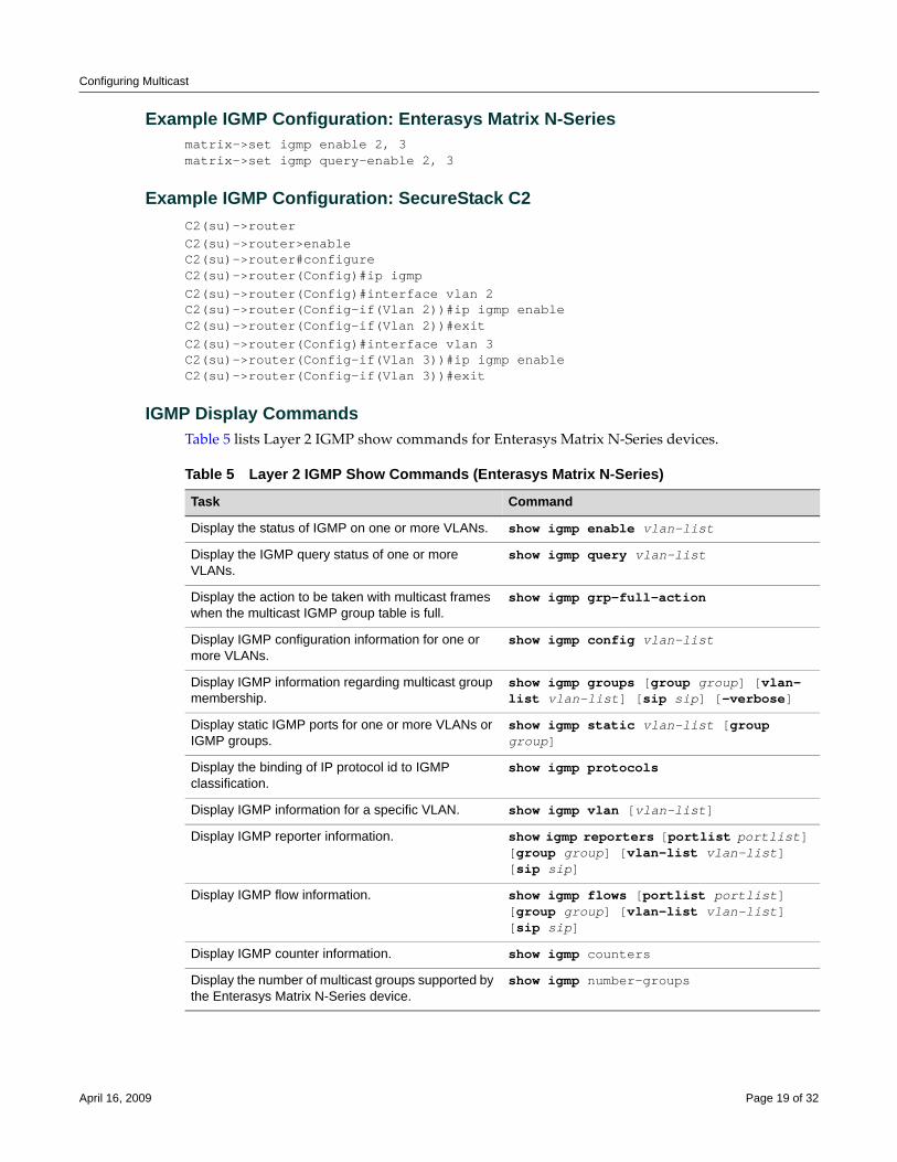
Configuring Multicast
Example IGMP Configuration: Enterasys Matrix N-Seriesmatrix->set igmp enable 2, 3matrix->set igmp query-enable 2, 3
Example IGMP Configuration: SecureStack C2C2(su)->routerC2(su)->router>enableC2(su)->router#configureC2(su)->router(Config)#ip igmpC2(su)->router(Config)#interface vlan 2C2(su)->router(Config-if(Vlan 2))#ip igmp enableC2(su)->router(Config-if(Vlan 2))#exitC2(su)->router(Config)#interface vlan 3C2(su)->router(Config-if(Vlan 3))#ip igmp enableC2(su)->router(Config-if(Vlan 3))#exit
IGMP Display CommandsTable 5 lists Layer 2 IGMP show commands for Enterasys Matrix N‐Series devices.
Table 5 Layer 2 IGMP Show Commands (Enterasys Matrix N-Series)
Task Command
Display the status of IGMP on one or more VLANs. show igmp enable vlan-list
Display the IGMP query status of one or more VLANs.
show igmp query vlan-list
Display the action to be taken with multicast frames when the multicast IGMP group table is full.
show igmp grp-full-action
Display IGMP configuration information for one or more VLANs.
show igmp config vlan-list
Display IGMP information regarding multicast group membership.
show igmp groups [group group] [vlan-list vlan-list] [sip sip] [-verbose]
Display static IGMP ports for one or more VLANs or IGMP groups.
show igmp static vlan-list [group group]
Display the binding of IP protocol id to IGMP classification.
show igmp protocols
Display IGMP information for a specific VLAN. show igmp vlan [vlan-list]
Display IGMP reporter information. show igmp reporters [portlist portlist] [group group] [vlan-list vlan-list] [sip sip]
Display IGMP flow information. show igmp flows [portlist portlist] [group group] [vlan-list vlan-list] [sip sip]
Display IGMP counter information. show igmp counters
Display the number of multicast groups supported by the Enterasys Matrix N-Series device.
show igmp number-groups
April 16, 2009 Page 19 of 32
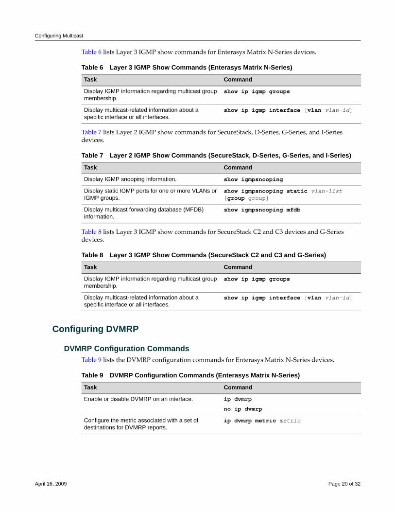
Configuring Multicast
Table 6 lists Layer 3 IGMP show commands for Enterasys Matrix N‐Series devices.
Table 7 lists Layer 2 IGMP show commands for SecureStack, D‐Series, G‐Series, and I‐Series devices.
Table 8 lists Layer 3 IGMP show commands for SecureStack C2 and C3 devices and G‐Series devices.
Configuring DVMRP
DVMRP Configuration CommandsTable 9 lists the DVMRP configuration commands for Enterasys Matrix N‐Series devices.
Table 6 Layer 3 IGMP Show Commands (Enterasys Matrix N-Series)
Task Command
Display IGMP information regarding multicast group membership.
show ip igmp groups
Display multicast-related information about a specific interface or all interfaces.
show ip igmp interface [vlan vlan-id]
Table 7 Layer 2 IGMP Show Commands (SecureStack, D-Series, G-Series, and I-Series)
Task Command
Display IGMP snooping information. show igmpsnooping
Display static IGMP ports for one or more VLANs or IGMP groups.
show igmpsnooping static vlan-list [group group]
Display multicast forwarding database (MFDB) information.
show igmpsnooping mfdb
Table 8 Layer 3 IGMP Show Commands (SecureStack C2 and C3 and G-Series)
Task Command
Display IGMP information regarding multicast group membership.
show ip igmp groups
Display multicast-related information about a specific interface or all interfaces.
show ip igmp interface [vlan vlan-id]
Table 9 DVMRP Configuration Commands (Enterasys Matrix N-Series)
Task Command
Enable or disable DVMRP on an interface. ip dvmrp
no ip dvmrp
Configure the metric associated with a set of destinations for DVMRP reports.
ip dvmrp metric metric
April 16, 2009 Page 20 of 32
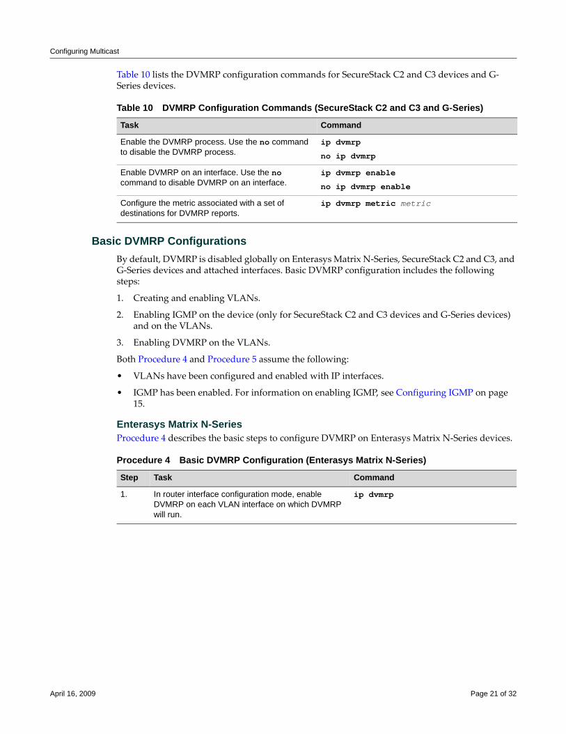
Configuring Multicast
Table 10 lists the DVMRP configuration commands for SecureStack C2 and C3 devices and G‐Series devices.
Basic DVMRP ConfigurationsBy default, DVMRP is disabled globally on Enterasys Matrix N‐Series, SecureStack C2 and C3, and G‐Series devices and attached interfaces. Basic DVMRP configuration includes the following steps:
1. Creating and enabling VLANs.
2. Enabling IGMP on the device (only for SecureStack C2 and C3 devices and G‐Series devices) and on the VLANs.
3. Enabling DVMRP on the VLANs.
Both Procedure 4 and Procedure 5 assume the following:
• VLANs have been configured and enabled with IP interfaces.
• IGMP has been enabled. For information on enabling IGMP, see Configuring IGMP on page 15.
Enterasys Matrix N-SeriesProcedure 4 describes the basic steps to configure DVMRP on Enterasys Matrix N‐Series devices.
Table 10 DVMRP Configuration Commands (SecureStack C2 and C3 and G-Series)
Task Command
Enable the DVMRP process. Use the no command to disable the DVMRP process.
ip dvmrp
no ip dvmrp
Enable DVMRP on an interface. Use the no command to disable DVMRP on an interface.
ip dvmrp enable
no ip dvmrp enable
Configure the metric associated with a set of destinations for DVMRP reports.
ip dvmrp metric metric
Procedure 4 Basic DVMRP Configuration (Enterasys Matrix N-Series)
Step Task Command
1. In router interface configuration mode, enable DVMRP on each VLAN interface on which DVMRP will run.
ip dvmrp
April 16, 2009 Page 21 of 32
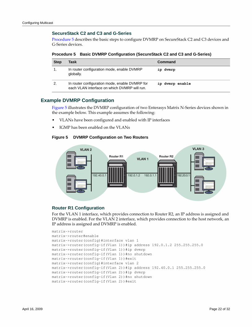
Configuring Multicast
SecureStack C2 and C3 and G-SeriesProcedure 5 describes the basic steps to configure DVMRP on SecureStack C2 and C3 devices and G‐Series devices.
Example DVMRP Configuration Figure 5 illustrates the DVMRP configuration of two Enterasys Matrix N‐Series devices shown in the example below. This example assumes the following:
• VLANs have been configured and enabled with IP interfaces
• IGMP has been enabled on the VLANs
Figure 5 DVMRP Configuration on Two Routers
Router R1 ConfigurationFor the VLAN 1 interface, which provides connection to Router R2, an IP address is assigned and DVMRP is enabled. For the VLAN 2 interface, which provides connection to the host network, an IP address is assigned and DVMRP is enabled.
matrix->routermatrix->router#enablematrix->router(config)#interface vlan 1matrix->router(config-if(Vlan 1))#ip address 192.0.1.2 255.255.255.0matrix->router(config-if(Vlan 1))#ip dvmrpmatrix->router(config-if(Vlan 1))#no shutdown matrix->router(config-if(Vlan 1))#exitmatrix->router(config)#interface vlan 2matrix->router(config-if(Vlan 2))#ip address 192.40.0.1 255.255.255.0matrix->router(config-if(Vlan 2))#ip dvmrpmatrix->router(config-if(Vlan 2))#no shutdownmatrix->router(config-if(Vlan 2))#exit
Procedure 5 Basic DVMRP Configuration (SecureStack C2 and C3 and G-Series)
Step Task Command
1. In router configuration mode, enable DVMRP globally.
ip dvmrp
2. In router configuration mode, enable DVMRP for each VLAN interface on which DVMRP will run.
ip dvmrp enable
VLAN 2 VLAN 3
VLAN 1
192.40.0.1 192.20.0.1192.0.1.2 192.0.1.1
Router R1 Router R2
April 16, 2009 Page 22 of 32
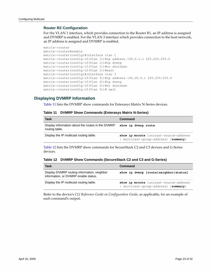
Configuring Multicast
Router R2 ConfigurationFor the VLAN 1 interface, which provides connection to the Router R1, an IP address is assigned and DVMRP is enabled. For the VLAN 3 interface which provides connection to the host network, an IP address is assigned and DVMRP is enabled.
matrix->routermatrix->router#enablematrix->router(config)#interface vlan 1matrix->router(config-if(Vlan 1))#ip address 192.0.1.1 255.255.255.0matrix->router(config-if(Vlan 1))#ip dvmrpmatrix->router(config-if(Vlan 1))#no shutdown matrix->router(config-if(Vlan 1))#exitmatrix->router(config)#interface vlan 3matrix->router(config-if(Vlan 3))#ip address 192.20.0.1 255.255.255.0matrix->router(config-if(Vlan 3))#ip dvmrpmatrix->router(config-if(Vlan 3))#no shutdownmatrix->router(config-if(Vlan 3))# exit
Displaying DVMRP InformationTable 11 lists the DVMRP show commands for Enterasys Matrix N‐Series devices.
Table 12 lists the DVMRP show commands for SecureStack C2 and C3 devices and G‐Series devices.
Refer to the device’s CLI Reference Guide or Configuration Guide, as applicable, for an example of each command’s output.
Table 11 DVMRP Show Commands (Enterasys Matrix N-Series)
Task Command
Display information about the routes in the DVMRP routing table.
show ip dvmrp route
Display the IP multicast routing table. show ip mroute [unicast-source-address | multicast-group-address] [summary]
Table 12 DVMRP Show Commands (SecureStack C2 and C3 and G-Series)
Task Command
Display DVMRP routing information, neighbor information, or DVMRP enable status.
show ip dvmrp [route|neighbor|status]
Display the IP multicast routing table. show ip mroute [unicast-source-address | multicast-group-address] [summary]
April 16, 2009 Page 23 of 32
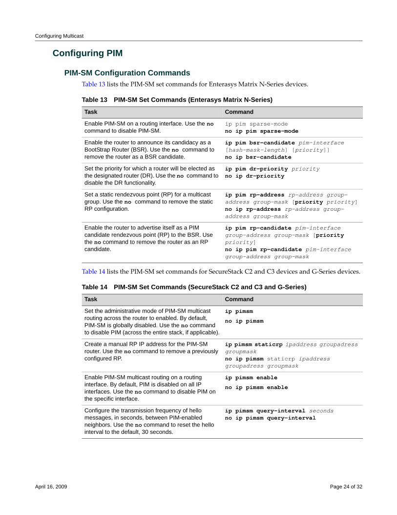
Configuring Multicast
Configuring PIM
PIM-SM Configuration CommandsTable 13 lists the PIM‐SM set commands for Enterasys Matrix N‐Series devices.
Table 14 lists the PIM‐SM set commands for SecureStack C2 and C3 devices and G‐Series devices.
Table 13 PIM-SM Set Commands (Enterasys Matrix N-Series)
Task Command
Enable PIM-SM on a routing interface. Use the no command to disable PIM-SM.
ip pim sparse-modeno ip pim sparse-mode
Enable the router to announce its candidacy as a BootStrap Router (BSR). Use the no command to remove the router as a BSR candidate.
ip pim bsr-candidate pim-interface [hash-mask-length] [priority]]no ip bsr-candidate
Set the priority for which a router will be elected as the designated router (DR). Use the no command to disable the DR functionality.
ip pim dr-priority priorityno ip dr-priority
Set a static rendezvous point (RP) for a multicast group. Use the no command to remove the static RP configuration.
ip pim rp-address rp-address group-address group-mask [priority priority]no ip rp-address rp-address group-address group-mask
Enable the router to advertise itself as a PIM candidate rendezvous point (RP) to the BSR. Use the no command to remove the router as an RP candidate.
ip pim rp-candidate pim-interface group-address group-mask [priority priority]no ip pim rp-candidate pim-interface group-address group-mask
Table 14 PIM-SM Set Commands (SecureStack C2 and C3 and G-Series)
Task Command
Set the administrative mode of PIM-SM multicast routing across the router to enabled. By default, PIM-SM is globally disabled. Use the no command to disable PIM (across the entire stack, if applicable).
ip pimsm
no ip pimsm
Create a manual RP IP address for the PIM-SM router. Use the no command to remove a previously configured RP.
ip pimsm staticrp ipaddress groupadress groupmaskno ip pimsm staticrp ipaddress groupadress groupmask
Enable PIM-SM multicast routing on a routing interface. By default, PIM is disabled on all IP interfaces. Use the no command to disable PIM on the specific interface.
ip pimsm enable
no ip pimsm enable
Configure the transmission frequency of hello messages, in seconds, between PIM-enabled neighbors. Use the no command to reset the hello interval to the default, 30 seconds.
ip pimsm query-interval secondsno ip pimsm query-interval
April 16, 2009 Page 24 of 32
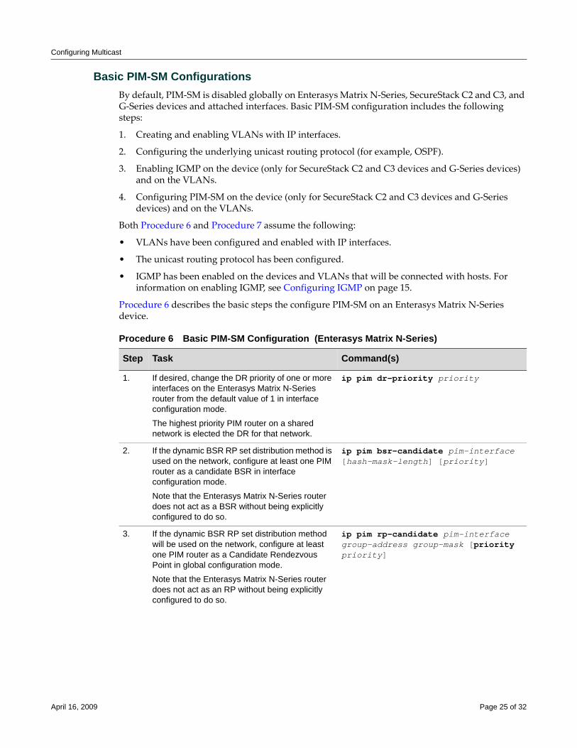
Configuring Multicast
Basic PIM-SM ConfigurationsBy default, PIM‐SM is disabled globally on Enterasys Matrix N‐Series, SecureStack C2 and C3, and G‐Series devices and attached interfaces. Basic PIM‐SM configuration includes the following steps:
1. Creating and enabling VLANs with IP interfaces.
2. Configuring the underlying unicast routing protocol (for example, OSPF).
3. Enabling IGMP on the device (only for SecureStack C2 and C3 devices and G‐Series devices) and on the VLANs.
4. Configuring PIM‐SM on the device (only for SecureStack C2 and C3 devices and G‐Series devices) and on the VLANs.
Both Procedure 6 and Procedure 7 assume the following:
• VLANs have been configured and enabled with IP interfaces.
• The unicast routing protocol has been configured.
• IGMP has been enabled on the devices and VLANs that will be connected with hosts. For information on enabling IGMP, see Configuring IGMP on page 15.
Procedure 6 describes the basic steps the configure PIM‐SM on an Enterasys Matrix N‐Series device.
Procedure 6 Basic PIM-SM Configuration (Enterasys Matrix N-Series)
Step Task Command(s)
1. If desired, change the DR priority of one or more interfaces on the Enterasys Matrix N-Series router from the default value of 1 in interface configuration mode.
The highest priority PIM router on a shared network is elected the DR for that network.
ip pim dr-priority priority
2. If the dynamic BSR RP set distribution method is used on the network, configure at least one PIM router as a candidate BSR in interface configuration mode.
Note that the Enterasys Matrix N-Series router does not act as a BSR without being explicitly configured to do so.
ip pim bsr-candidate pim-interface [hash-mask-length] [priority]
3. If the dynamic BSR RP set distribution method will be used on the network, configure at least one PIM router as a Candidate Rendezvous Point in global configuration mode.
Note that the Enterasys Matrix N-Series router does not act as an RP without being explicitly configured to do so.
ip pim rp-candidate pim-interface group-address group-mask [priority priority]
April 16, 2009 Page 25 of 32
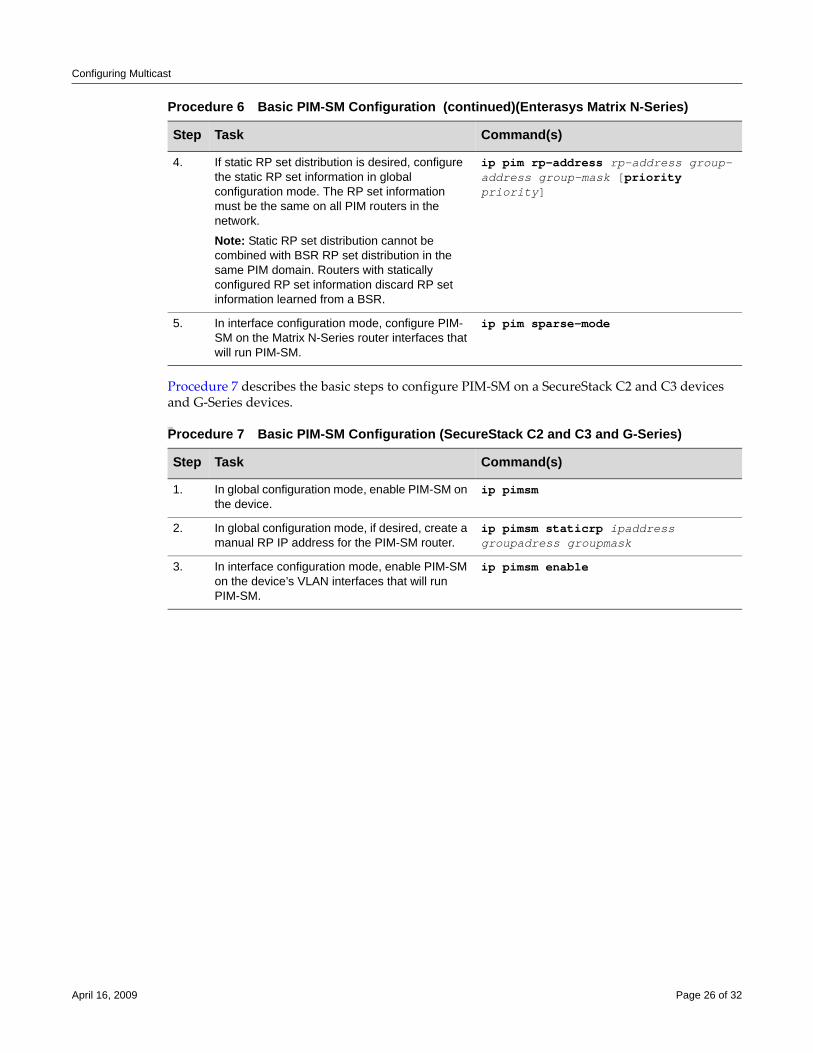
Configuring Multicast
Procedure 7 describes the basic steps to configure PIM‐SM on a SecureStack C2 and C3 devices and G‐Series devices.)))))
4. If static RP set distribution is desired, configure the static RP set information in global configuration mode. The RP set information must be the same on all PIM routers in the network.
Note: Static RP set distribution cannot be combined with BSR RP set distribution in the same PIM domain. Routers with statically configured RP set information discard RP set information learned from a BSR.
ip pim rp-address rp-address group-address group-mask [priority priority]
5. In interface configuration mode, configure PIM-SM on the Matrix N-Series router interfaces that will run PIM-SM.
ip pim sparse-mode
Procedure 7 Basic PIM-SM Configuration (SecureStack C2 and C3 and G-Series)
Step Task Command(s)
1. In global configuration mode, enable PIM-SM on the device.
ip pimsm
2. In global configuration mode, if desired, create a manual RP IP address for the PIM-SM router.
ip pimsm staticrp ipaddress groupadress groupmask
3. In interface configuration mode, enable PIM-SM on the device’s VLAN interfaces that will run PIM-SM.
ip pimsm enable
Procedure 6 Basic PIM-SM Configuration (continued)(Enterasys Matrix N-Series)
Step Task Command(s)
April 16, 2009 Page 26 of 32
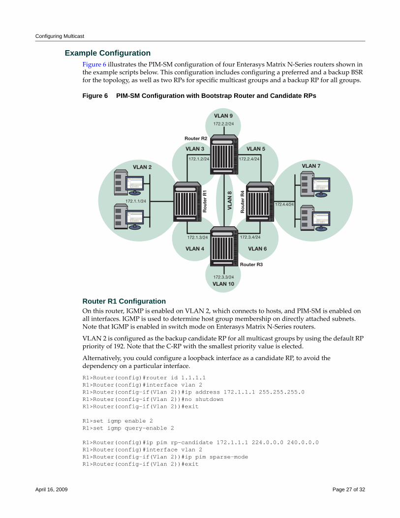
Configuring Multicast
Example ConfigurationFigure 6 illustrates the PIM‐SM configuration of four Enterasys Matrix N‐Series routers shown in the example scripts below. This configuration includes configuring a preferred and a backup BSR for the topology, as well as two RPs for specific multicast groups and a backup RP for all groups.
Figure 6 PIM-SM Configuration with Bootstrap Router and Candidate RPs
Router R1 ConfigurationOn this router, IGMP is enabled on VLAN 2, which connects to hosts, and PIM‐SM is enabled on all interfaces. IGMP is used to determine host group membership on directly attached subnets. Note that IGMP is enabled in switch mode on Enterasys Matrix N‐Series routers.
VLAN 2 is configured as the backup candidate RP for all multicast groups by using the default RP priority of 192. Note that the C‐RP with the smallest priority value is elected.
Alternatively, you could configure a loopback interface as a candidate RP, to avoid the dependency on a particular interface.
R1>Router(config)#router id 1.1.1.1R1>Router(config)#interface vlan 2R1>Router(config-if(Vlan 2))#ip address 172.1.1.1 255.255.255.0R1>Router(config-if(Vlan 2))#no shutdownR1>Router(config-if(Vlan 2))#exit
R1>set igmp enable 2R1>set igmp query-enable 2
R1>Router(config)#ip pim rp-candidate 172.1.1.1 224.0.0.0 240.0.0.0R1>Router(config)#interface vlan 2R1>Router(config-if(Vlan 2))#ip pim sparse-modeR1>Router(config-if(Vlan 2))#exit
VLAN 2
VLAN 3
VLAN 4 VLAN 6
VLAN 5
VLAN 9
VLA
N 8
VLAN 10
VLAN 7
172.1.1/24
172.1.2/24 172.2.4/24
172.3.4/24172.1.3/24
172.2.2/24
172.3.3/24
172.4.4/24R
out
er R
1
Ro
uter
R4
Router R2
Router R3
April 16, 2009 Page 27 of 32
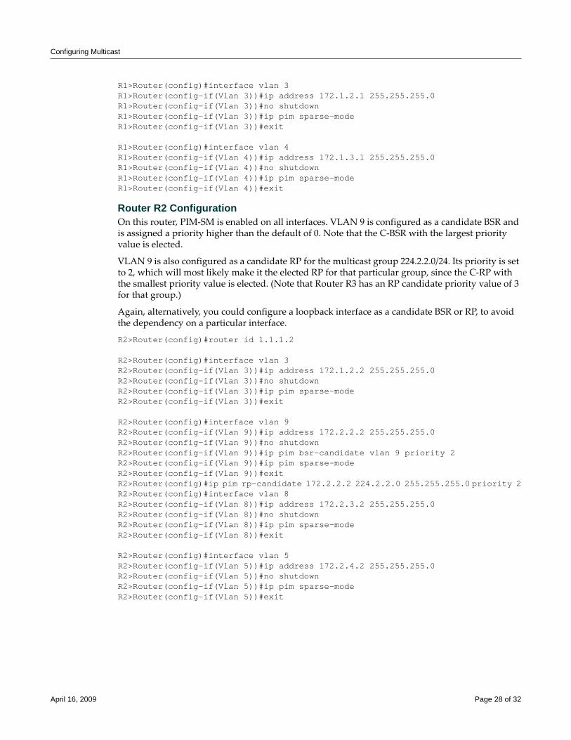
Configuring Multicast
R1>Router(config)#interface vlan 3R1>Router(config-if(Vlan 3))#ip address 172.1.2.1 255.255.255.0R1>Router(config-if(Vlan 3))#no shutdownR1>Router(config-if(Vlan 3))#ip pim sparse-modeR1>Router(config-if(Vlan 3))#exit
R1>Router(config)#interface vlan 4R1>Router(config-if(Vlan 4))#ip address 172.1.3.1 255.255.255.0R1>Router(config-if(Vlan 4))#no shutdownR1>Router(config-if(Vlan 4))#ip pim sparse-modeR1>Router(config-if(Vlan 4))#exit
Router R2 ConfigurationOn this router, PIM‐SM is enabled on all interfaces. VLAN 9 is configured as a candidate BSR and is assigned a priority higher than the default of 0. Note that the C‐BSR with the largest priority value is elected.
VLAN 9 is also configured as a candidate RP for the multicast group 224.2.2.0/24. Its priority is set to 2, which will most likely make it the elected RP for that particular group, since the C‐RP with the smallest priority value is elected. (Note that Router R3 has an RP candidate priority value of 3 for that group.)
Again, alternatively, you could configure a loopback interface as a candidate BSR or RP, to avoid the dependency on a particular interface.
R2>Router(config)#router id 1.1.1.2
R2>Router(config)#interface vlan 3R2>Router(config-if(Vlan 3))#ip address 172.1.2.2 255.255.255.0R2>Router(config-if(Vlan 3))#no shutdownR2>Router(config-if(Vlan 3))#ip pim sparse-modeR2>Router(config-if(Vlan 3))#exit
R2>Router(config)#interface vlan 9R2>Router(config-if(Vlan 9))#ip address 172.2.2.2 255.255.255.0R2>Router(config-if(Vlan 9))#no shutdownR2>Router(config-if(Vlan 9))#ip pim bsr-candidate vlan 9 priority 2 R2>Router(config-if(Vlan 9))#ip pim sparse-modeR2>Router(config-if(Vlan 9))#exitR2>Router(config)#ip pim rp-candidate 172.2.2.2 224.2.2.0 255.255.255.0 priority 2R2>Router(config)#interface vlan 8R2>Router(config-if(Vlan 8))#ip address 172.2.3.2 255.255.255.0R2>Router(config-if(Vlan 8))#no shutdownR2>Router(config-if(Vlan 8))#ip pim sparse-modeR2>Router(config-if(Vlan 8))#exit
R2>Router(config)#interface vlan 5R2>Router(config-if(Vlan 5))#ip address 172.2.4.2 255.255.255.0R2>Router(config-if(Vlan 5))#no shutdownR2>Router(config-if(Vlan 5))#ip pim sparse-modeR2>Router(config-if(Vlan 5))#exit
April 16, 2009 Page 28 of 32
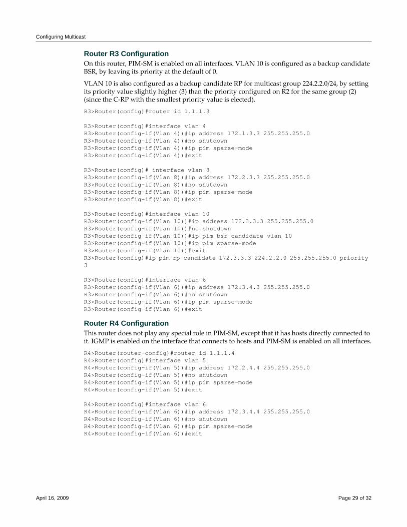
Configuring Multicast
Router R3 ConfigurationOn this router, PIM‐SM is enabled on all interfaces. VLAN 10 is configured as a backup candidate BSR, by leaving its priority at the default of 0.
VLAN 10 is also configured as a backup candidate RP for multicast group 224.2.2.0/24, by setting its priority value slightly higher (3) than the priority configured on R2 for the same group (2) (since the C‐RP with the smallest priority value is elected).
R3>Router(config)#router id 1.1.1.3
R3>Router(config)#interface vlan 4R3>Router(config-if(Vlan 4))#ip address 172.1.3.3 255.255.255.0R3>Router(config-if(Vlan 4))#no shutdownR3>Router(config-if(Vlan 4))#ip pim sparse-modeR3>Router(config-if(Vlan 4))#exit
R3>Router(config)# interface vlan 8R3>Router(config-if(Vlan 8))#ip address 172.2.3.3 255.255.255.0R3>Router(config-if(Vlan 8))#no shutdownR3>Router(config-if(Vlan 8))#ip pim sparse-modeR3>Router(config-if(Vlan 8))#exit
R3>Router(config)#interface vlan 10R3>Router(config-if(Vlan 10))#ip address 172.3.3.3 255.255.255.0R3>Router(config-if(Vlan 10))#no shutdownR3>Router(config-if(Vlan 10))#ip pim bsr-candidate vlan 10R3>Router(config-if(Vlan 10))#ip pim sparse-modeR3>Router(config-if(Vlan 10))#exitR3>Router(config)#ip pim rp-candidate 172.3.3.3 224.2.2.0 255.255.255.0 priority 3
R3>Router(config)#interface vlan 6R3>Router(config-if(Vlan 6))#ip address 172.3.4.3 255.255.255.0R3>Router(config-if(Vlan 6))#no shutdownR3>Router(config-if(Vlan 6))#ip pim sparse-modeR3>Router(config-if(Vlan 6))#exit
Router R4 ConfigurationThis router does not play any special role in PIM‐SM, except that it has hosts directly connected to it. IGMP is enabled on the interface that connects to hosts and PIM‐SM is enabled on all interfaces.
R4>Router(router-config)#router id 1.1.1.4R4>Router(config)#interface vlan 5R4>Router(config-if(Vlan 5))#ip address 172.2.4.4 255.255.255.0R4>Router(config-if(Vlan 5))#no shutdownR4>Router(config-if(Vlan 5))#ip pim sparse-modeR4>Router(config-if(Vlan 5))#exit
R4>Router(config)#interface vlan 6R4>Router(config-if(Vlan 6))#ip address 172.3.4.4 255.255.255.0R4>Router(config-if(Vlan 6))#no shutdownR4>Router(config-if(Vlan 6))#ip pim sparse-modeR4>Router(config-if(Vlan 6))#exit
April 16, 2009 Page 29 of 32
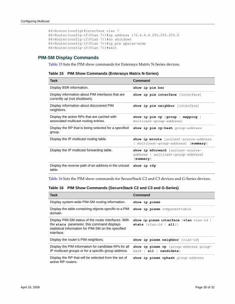
Configuring Multicast
R4>Router(config)#interface vlan 7R4>Router(config-if(Vlan 7))#ip address 172.4.4.4 255.255.255.0R4>Router(config-if(Vlan 7))#no shutdownR4>Router(config-if(Vlan 7))#ip pim sparse-modeR4>Router(config-if(Vlan 7))#exit
PIM-SM Display CommandsTable 15 lists the PIM show commands for Enterasys Matrix N‐Series devices.
Table 16 lists the PIM show commands for SecureStack C2 and C3 devices and G‐Series devices.
Table 15 PIM Show Commands (Enterasys Matrix N-Series)
Task Command
Display BSR information. show ip pim bsr
Display information about PIM interfaces that are currently up (not shutdown).
show ip pim interface [interface]
Display information about discovered PIM neighbors.
show ip pim neighbor [interface]
Display the active RPs that are cached with associated multicast routing entries.
show ip pim rp [group | mapping | multicast-group-address]
Display the RP that is being selected for a specified group.
show ip pim rp-hash group-address
Display the IP multicast routing table. show ip mroute [unicast-source-address | multicast-group-address] [summary]
Display the IP multicast forwarding table. show ip mforward [unicast-source-address | multicast-group-address] [summary]
Display the reverse path of an address in the unicast table.
show ip rfp
Table 16 PIM Show Commands (SecureStack C2 and C3 and G-Series)
Task Command
Display system-wide PIM-SM routing information. show ip pimsm
Display the table containing objects specific to a PIM domain.
show ip pimsm componenttable
Display PIM-SM status of the router interfaces. With the stats parameter, this command displays statistical information for PIM-SM on the specified interface.
show ip pimsm interface {vlan vlan-id | stats {vlan-id | all}}
Display the router’s PIM neighbors. show ip pimsm neighbor [vlan-id]
Display the PIM information for candidate RPs for all IP multicast groups or for a specific group address.
show ip pimsm rp {group-address group-mask | all | candidate}
Display the RP that will be selected from the set of active RP routers.
show ip pimsm rphash group-address
April 16, 2009 Page 30 of 32
Refer to the device’s CLI Reference Guide or Configuration Guide, as applicable, for a description of the output of each command.
Display the PIM-SM static RP information. show ip pimsm staticrp
Display the IP multicast routing table. show ip mroute [unicast-source-address | multicast-group-address] [summary]
Table 16 PIM Show Commands (SecureStack C2 and C3 and G-Series) (continued)
Task Command

Enterasys Networks reserves the right to make changes in specifications and other information contained in this document and its web site without prior notice. The reader should in all cases consult Enterasys Networks to determine whether any such changes have been made.
The hardware, firmware, or software described in this document is subject to change without notice.
IN NO EVENT SHALL ENTERASYS NETWORKS BE LIABLE FOR ANY INCIDENTAL, INDIRECT, SPECIAL, OR CONSEQUENTIAL DAMAGES WHATSOEVER (INCLUDING BUT NOT LIMITED TO LOST PROFITS) ARISING OUT OF OR RELATED TO THIS DOCUMENT, WEB SITE, OR THE INFORMATION CONTAINED IN THEM, EVEN IF ENTERASYS NETWORKS HAS BEEN ADVISED OF, KNEW OF, OR SHOULD HAVE KNOWN OF, THE POSSIBILITY OF SUCH DAMAGES.
Enterasys Networks, Inc.50 Minuteman RoadAndover, MA 01810
© 2009 Enterasys Networks, Inc. All rights reserved.
ENTERASYS, ENTERASYS NETWORKS, ENTERASYS SECURE NETWORKS, NETSIGHT, ENTERASYS NETSIGHT, ENTERASYS MATRIX, and any logos associated therewith, are trademarks or registered trademarks of Enterasys Networks, Inc., in the United States and/or other countries. For a complete list of Enterasys trademarks, see http://www.enterasys.com/company/trademarks.aspx.
All other product names mentioned in this manual may be trademarks or registered trademarks of their respective companies.
Revision History
Date Description
09-02-08 New document
04-16-09 Added 256MB minimum memory requirement for PIM.
Configuring Network Address Translation (NAT)
This document provides the following information about configuring Network Address Translation on the Enterasys Matrix® N‐Series and the Enterasys S‐Series® platforms.
What is Network Address Translation?Network Address Translation (NAT) and Network Address Port Translation (NAPT) are methods of concealing a set of host addresses on a private network behind a pool of public addresses. Together they are referred to as traditional NAT. A traditional NAT configuration is made up of a private network and a public network that are connected by a router with NAT enabled on it.
Basic NAT is a method by which IP addresses are mapped from one group of addresses to another, transparent to the end user. A basic NAT translation is always between a single private IP address and a single public IP address.
NAPT is a method by which many private network addresses, along with each private address’ associated TCP/UDP port, are translated into a single public network address and its associated TCP/UDP ports. Given that there is only a single public IP address associated with the translations, it is the public port the private address and its port are associated with that allows for the uniqueness of each translation.
In addition, the following features are also supported:
• Static and Dynamic NAT Pool Binding
• FTP, DNS, and ICMP (with five different error messages) software path NAT translation
For information about... Refer to page...
What is Network Address Translation? 1
Why Would I Use NAT in My Network? 2
How Can I Implement NAT? 2
NAT Overview 3
Configuring NAT 9
NAT Configuration Examples 12
Terms and Definitions 17
September 08, 2010 Page 1 of 18
Why Would I Use NAT in My Network?
Why Would I Use NAT in My Network?Enterasys support for NAT provides a practical solution for organizations who wish to streamline their IP addressing schemes. NAT operates on a router connecting a private network to a public network, simplifying network design and conserving IP addresses. NAT can help organizations merge multiple networks together and enhance network security by:
• Helping to prevent malicious activity initiated by outside hosts from entering the corporate network
• Improving the reliability of local systems by stopping worms
• Augmenting privacy by keeping private intranet addresses hidden from view of the public internet, thereby inhibiting scans
• Limiting the number of IP addresses used for private intranets that are required to be registered with the Internet Assigned Numbers Authority (IANA)
• Conserving the number of global IP addresses needed by a private intranet
How Can I Implement NAT?To implement NAT in your network:
• Enable NAT on both the inside (local) and outside (public) interfaces to be used for translation
• If you intend to use inside source address dynamic translation (see “Dynamic Inside Address Translations” on page 5 for details):
– Define an access‐list of inside addresses
– Define a NAT address pool of outside addresses
– Enable dynamic translation of inside addresses specifying an access‐list of inside addresses and a NAT address pool of outside addresses
– Optionally configure overload for NAPT (defaults to NAT)
– Optionally specify the interface to which translations are applied
• If you intend to use inside source address static translation (see “Static Inside Address Translation” on page 3 for details), enable inside source address static translation in the appropriate NAT or NAPT context
• Optionally change the NAT FTP control port from its default of 21
• Optionally enable force flows to force all flows to be translated between outside and inside addresses
• Optionally modify maximum allowed entries and NAT translation timeout values
September 08, 2010 Page 2 of 18
NAT Overview
NAT OverviewThis section provides an overview of NAT configuration.
NAT ConfigurationA traditional NAT configuration is made up of a private network or intranet, a public network, and a router that interconnects the two networks. The private network is made up of one or more hosts and devices each assigned an inside (internal) address that is not intended to be directly connectable to a public network host or device. The public network hosts or devices have outside (external) uniquely registered public addresses. The router interconnecting the private and public networks support traditional NAT. It is NAT’s responsibility to translate the inside address to a unique outside address to facilitate communication with the public network for intranet devices.
NAT allows translations between IP addresses. NAPT allows translations between multiple inside addresses and their associated ports and a single outside IP address and its associated ports. NAT and NAPT support both static and dynamic inside address translation.
Static Inside Address TranslationStatic inside address translations are one‐to‐one bindings between the inside and outside IP addresses. A static address binding does not expire until the command that defines the binding is negated. When configuring NAT for static inside address translation, you assign a local IP address and a global IP address to the binding. When configuring NAPT for static inside address translation, you assign a local IP address and one of its associated L4 ports and a global IP address and one of its associated L4 ports to the binding. You also specify whether the packet protocol is TCP or UDP for this binding.
NAT Static Inside Address TranslationFigure 1 on page 4 displays a basic NAT static inside address translation overview. Client1 has a source address of 10.1.1.1 (its own IP address) and a destination address of 200.1.1.50 (the Server1 IP address). The static translation is configured between the local IP address (Client1’s own IP address) and the global IP address 200.1.1.1 (an available public network address).
A packet arrives at the NAT router from Client1 with a source address of 10.1.1.1, but leaves the NAT router with a source address of 200.1.1.1. In both cases the destination is for Server1’s IP address of 200.1.1.50. From Server1’s point of view, Client1’s IP address is 200.1.1.1. Server1 doesn’t know anything about its actual IP address of 10.1.1.1.
Notes: NAT is currently supported on the S-Series and N-Series products. This document details the configuration of NAT for the S-Series and N-Series products.
NAT is an advanced routing feature that must be enabled with a license key on the N-Series router. An advanced routing license is currently not required on the S-Series platform. If you have purchased an advanced license key, and have enabled routing on the device, you must activate your license as described in the configuration guide that comes with your Enterasys N-Series product in order to enable the NAT command set. If you wish to purchase an advanced routing license, contact Enterasys Networks Sales.
A minimum of 256 MB of memory is required on all modules in order to enable NAT. See the SDRAM field of the show system hardware command to display the amount of memory installed on a module. An N-Series module memory can be upgraded to 256 MB using the DFE-256MB-UGK memory kit.
September 08, 2010 Page 3 of 18
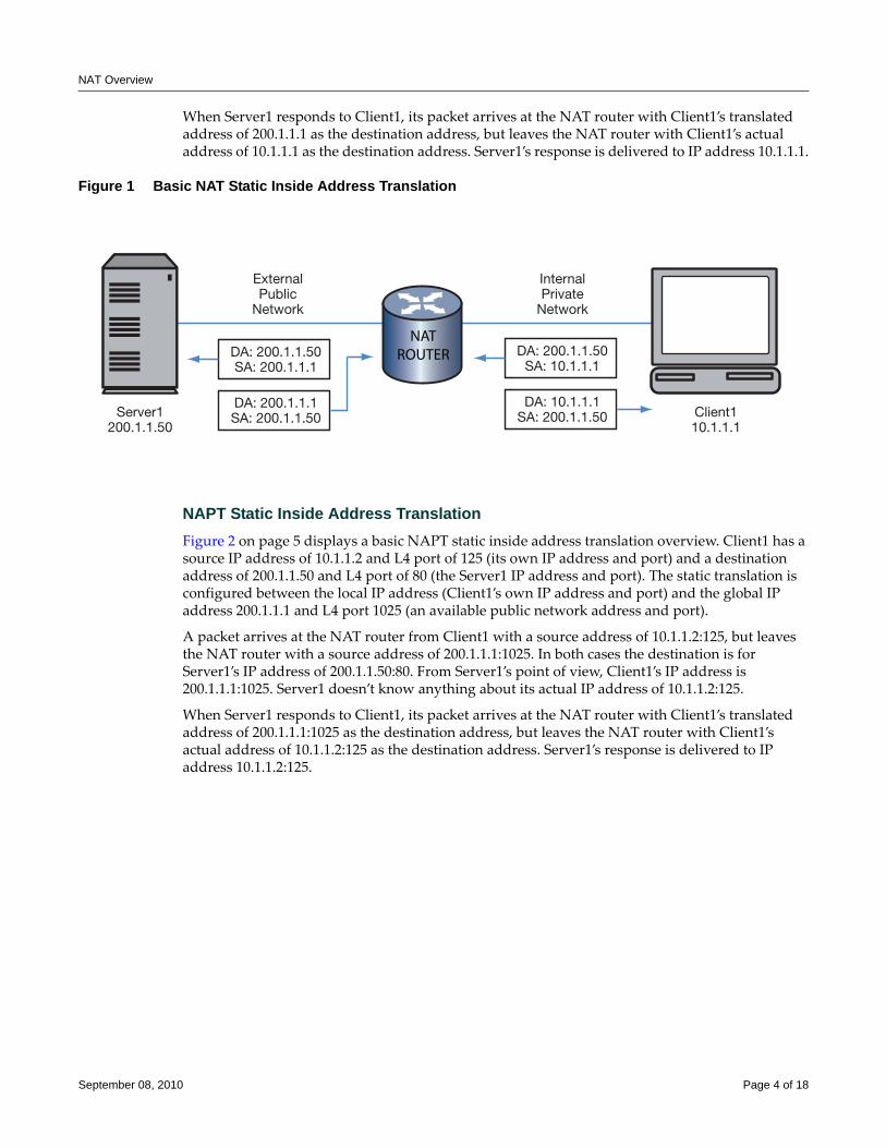
NAT Overview
When Server1 responds to Client1, its packet arrives at the NAT router with Client1’s translated address of 200.1.1.1 as the destination address, but leaves the NAT router with Client1’s actual address of 10.1.1.1 as the destination address. Server1’s response is delivered to IP address 10.1.1.1.
Figure 1 Basic NAT Static Inside Address Translation
NAPT Static Inside Address TranslationFigure 2 on page 5 displays a basic NAPT static inside address translation overview. Client1 has a source IP address of 10.1.1.2 and L4 port of 125 (its own IP address and port) and a destination address of 200.1.1.50 and L4 port of 80 (the Server1 IP address and port). The static translation is configured between the local IP address (Client1’s own IP address and port) and the global IP address 200.1.1.1 and L4 port 1025 (an available public network address and port).
A packet arrives at the NAT router from Client1 with a source address of 10.1.1.2:125, but leaves the NAT router with a source address of 200.1.1.1:1025. In both cases the destination is for Server1’s IP address of 200.1.1.50:80. From Server1’s point of view, Client1’s IP address is 200.1.1.1:1025. Server1 doesn’t know anything about its actual IP address of 10.1.1.2:125.
When Server1 responds to Client1, its packet arrives at the NAT router with Client1’s translated address of 200.1.1.1:1025 as the destination address, but leaves the NAT router with Client1’s actual address of 10.1.1.2:125 as the destination address. Server1’s response is delivered to IP address 10.1.1.2:125.
Client110.1.1.1
Server1200.1.1.50
NATROUTERDA: 200.1.1.50
SA: 200.1.1.1
ExternalPublic
Network
InternalPrivate
Network
DA: 200.1.1.1SA: 200.1.1.50
DA: 200.1.1.50SA: 10.1.1.1
DA: 10.1.1.1SA: 200.1.1.50
September 08, 2010 Page 4 of 18
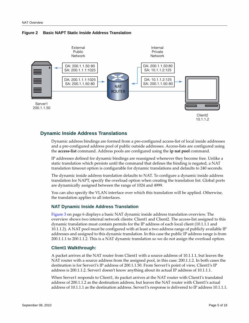
NAT Overview
Figure 2 Basic NAPT Static Inside Address Translation
Dynamic Inside Address TranslationsDynamic address bindings are formed from a pre‐configured access‐list of local inside addresses and a pre‐configured address pool of public outside addresses. Access‐lists are configured using the access‐list command. Address pools are configured using the ip nat pool command.
IP addresses defined for dynamic bindings are reassigned whenever they become free. Unlike a static translation which persists until the command that defines the binding is negated, a NAT translation timeout option is configurable for dynamic translations and defaults to 240 seconds.
The dynamic inside address translation defaults to NAT. To configure a dynamic inside address translation for NAPT, specify the overload option when creating the translation list. Global ports are dynamically assigned between the range of 1024 and 4999.
You can also specify the VLAN interface over which this translation will be applied. Otherwise, the translation applies to all interfaces.
NAT Dynamic Inside Address TranslationFigure 3 on page 6 displays a basic NAT dynamic inside address translation overview. The overview shows two internal network clients: Client1 and Client2. The access‐list assigned to this dynamic translation must contain permits for the IP address of each local client (10.1.1.1 and 10.1.1.2). A NAT pool must be configured with at least a two address range of publicly available IP addresses and assigned to this dynamic translation. In this case the public IP address range is from 200.1.1.1 to 200.1.1.2. This is a NAT dynamic translation so we do not assign the overload option.
Client1 Walkthrough:A packet arrives at the NAT router from Client1 with a source address of 10.1.1.1, but leaves the NAT router with a source address from the assigned pool, in this case: 200.1.1.2. In both cases the destination is for Server1’s IP address of 200.1.1.50. From Server1’s point of view, Client1’s IP address is 200.1.1.2. Server1 doesn’t know anything about its actual IP address of 10.1.1.1.
When Server1 responds to Client1, its packet arrives at the NAT router with Client1’s translated address of 200.1.1.2 as the destination address, but leaves the NAT router with Client1’s actual address of 10.1.1.1 as the destination address. Server1’s response is delivered to IP address 10.1.1.1.
Client210.1.1.2
Server1200.1.1.50
NATROUTER
DA: 200.1.1.50:80SA: 200.1.1.1:1025
ExternalPublic
Network
InternalPrivate
Network
DA: 200.1.1.1:1025SA: 200.1.1.50:80
DA: 200.1.1.50:80SA: 10.1.1.2:125
DA: 10.1.1.2:125SA: 200.1.1.50:80
September 08, 2010 Page 5 of 18
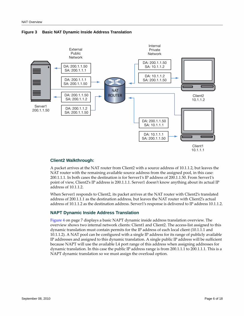
NAT Overview
Figure 3 Basic NAT Dynamic Inside Address Translation
Client2 Walkthrough:A packet arrives at the NAT router from Client2 with a source address of 10.1.1.2, but leaves the NAT router with the remaining available source address from the assigned pool, in this case: 200.1.1.1. In both cases the destination is for Server1’s IP address of 200.1.1.50. From Server1’s point of view, Client2’s IP address is 200.1.1.1. Server1 doesn’t know anything about its actual IP address of 10.1.1.2.
When Server1 responds to Client2, its packet arrives at the NAT router with Client2’s translated address of 200.1.1.1 as the destination address, but leaves the NAT router with Client2’s actual address of 10.1.1.2 as the destination address. Server1’s response is delivered to IP address 10.1.1.2.
NAPT Dynamic Inside Address TranslationFigure 4 on page 7 displays a basic NAPT dynamic inside address translation overview. The overview shows two internal network clients: Client1 and Client2. The access‐list assigned to this dynamic translation must contain permits for the IP address of each local client (10.1.1.1 and 10.1.1.2). A NAT pool can be configured with a single IP address for its range of publicly available IP addresses and assigned to this dynamic translation. A single public IP address will be sufficient because NAPT will use the available L4 port range of this address when assigning addresses for dynamic translation. In this case the public IP address range is from 200.1.1.1 to 200.1.1.1. This is a NAPT dynamic translation so we must assign the overload option.
Server1200.1.1.50
NATROUTERDA: 200.1.1.50
SA: 200.1.1.2
DA: 200.1.1.2SA: 200.1.1.50
DA: 200.1.1.50SA: 10.1.1.1
DA: 10.1.1.1SA: 200.1.1.50
Client210.1.1.2
DA: 200.1.1.50SA: 200.1.1.1
ExternalPublic
Network
InternalPrivate
Network
DA: 200.1.1.1SA: 200.1.1.50
DA: 200.1.1.50SA: 10.1.1.2
DA: 10.1.1.2SA: 200.1.1.50
Client110.1.1.1
September 08, 2010 Page 6 of 18
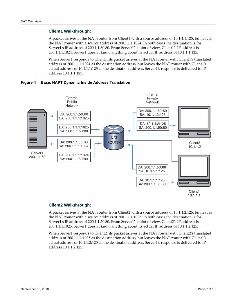
NAT Overview
Client1 Walkthrough:A packet arrives at the NAT router from Client1 with a source address of 10.1.1.1:125, but leaves the NAT router with a source address of 200.1.1.1:1024. In both cases the destination is for Server1’s IP address of 200.1.1.50:80. From Server1’s point of view, Client1’s IP address is 200.1.1.1:1024. Server1 doesn’t know anything about its actual IP address of 10.1.1.1:125.
When Server1 responds to Client1, its packet arrives at the NAT router with Client1’s translated address of 200.1.1.1:1024 as the destination address, but leaves the NAT router with Client1’s actual address of 10.1.1.1:125 as the destination address. Server1’s response is delivered to IP address 10.1.1.1:125.
Figure 4 Basic NAPT Dynamic Inside Address Translation
Client2 Walkthrough:A packet arrives at the NAT router from Client2 with a source address of 10.1.1.2:125, but leaves the NAT router with a source address of 200.1.1.1:1025. In both cases the destination is for Server1’s IP address of 200.1.1.50:80. From Server1’s point of view, Client2’s IP address is 200.1.1.1:1025. Server1 doesn’t know anything about its actual IP address of 10.1.1.2:125.
When Server1 responds to Client2, its packet arrives at the NAT router with Client2’s translated address of 200.1.1.1:1025 as the destination address, but leaves the NAT router with Client1’s actual address of 10.1.1.2:125 as the destination address. Server1’s response is delivered to IP address 10.1.1.2:125.
Server1200.1.1.50
NATROUTERDA: 200.1.1.50:80
SA: 200.1.1.1:1024
DA: 200.1.1.1:1024SA: 200.1.1.50:80
DA: 200.1.1.50:80SA: 10.1.1.1:125
DA: 10.1.1.1:125SA: 200.1.1.50:80
Client210.1.1.2
DA: 200.1.1.50:80SA: 200.1.1.1:1025
ExternalPublic
Network
InternalPrivate
Network
DA: 200.1.1.1:1025SA: 200.1.1.50:80
DA: 200.1.1.50:80SA: 10.1.1.2:125
DA: 10.1.1.2:125SA: 200.1.1.50:80
Client110.1.1.1
September 08, 2010 Page 7 of 18
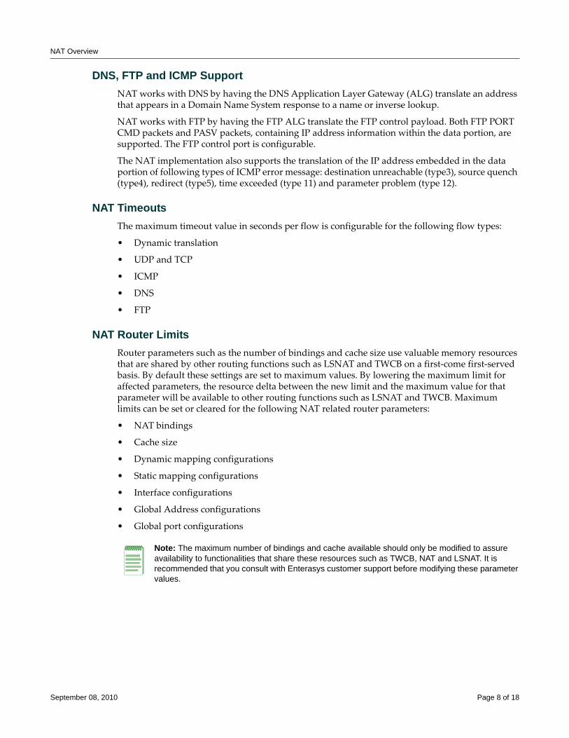
NAT Overview
DNS, FTP and ICMP SupportNAT works with DNS by having the DNS Application Layer Gateway (ALG) translate an address that appears in a Domain Name System response to a name or inverse lookup.
NAT works with FTP by having the FTP ALG translate the FTP control payload. Both FTP PORT CMD packets and PASV packets, containing IP address information within the data portion, are supported. The FTP control port is configurable.
The NAT implementation also supports the translation of the IP address embedded in the data portion of following types of ICMP error message: destination unreachable (type3), source quench (type4), redirect (type5), time exceeded (type 11) and parameter problem (type 12).
NAT TimeoutsThe maximum timeout value in seconds per flow is configurable for the following flow types:
• Dynamic translation
• UDP and TCP
• ICMP
• DNS
• FTP
NAT Router LimitsRouter parameters such as the number of bindings and cache size use valuable memory resources that are shared by other routing functions such as LSNAT and TWCB on a first‐come first‐served basis. By default these settings are set to maximum values. By lowering the maximum limit for affected parameters, the resource delta between the new limit and the maximum value for that parameter will be available to other routing functions such as LSNAT and TWCB. Maximum limits can be set or cleared for the following NAT related router parameters:
• NAT bindings
• Cache size
• Dynamic mapping configurations
• Static mapping configurations
• Interface configurations
• Global Address configurations
• Global port configurations
Note: The maximum number of bindings and cache available should only be modified to assure availability to functionalities that share these resources such as TWCB, NAT and LSNAT. It is recommended that you consult with Enterasys customer support before modifying these parameter values.
September 08, 2010 Page 8 of 18
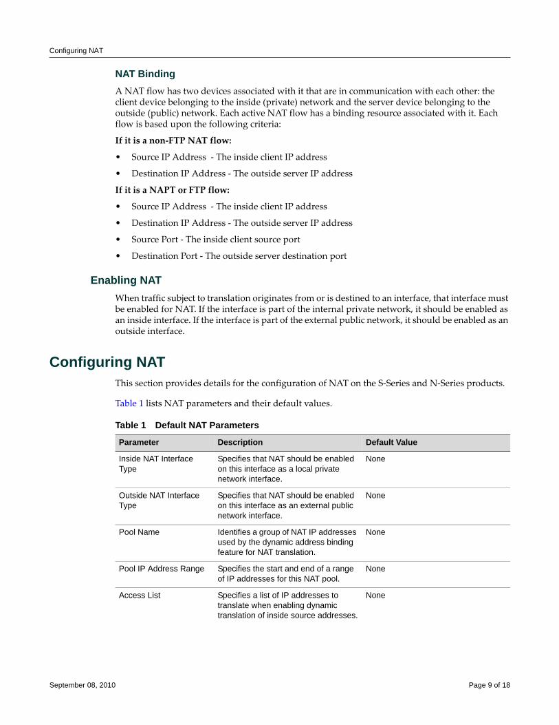
Configuring NAT
NAT BindingA NAT flow has two devices associated with it that are in communication with each other: the client device belonging to the inside (private) network and the server device belonging to the outside (public) network. Each active NAT flow has a binding resource associated with it. Each flow is based upon the following criteria:
If it is a non‐FTP NAT flow:
• Source IP Address ‐ The inside client IP address
• Destination IP Address ‐ The outside server IP address
If it is a NAPT or FTP flow:
• Source IP Address ‐ The inside client IP address
• Destination IP Address ‐ The outside server IP address
• Source Port ‐ The inside client source port
• Destination Port ‐ The outside server destination port
Enabling NATWhen traffic subject to translation originates from or is destined to an interface, that interface must be enabled for NAT. If the interface is part of the internal private network, it should be enabled as an inside interface. If the interface is part of the external public network, it should be enabled as an outside interface.
Configuring NATThis section provides details for the configuration of NAT on the S‐Series and N‐Series products.
Table 1 lists NAT parameters and their default values.
Table 1 Default NAT Parameters
Parameter Description Default Value
Inside NAT Interface Type
Specifies that NAT should be enabled on this interface as a local private network interface.
None
Outside NAT Interface Type
Specifies that NAT should be enabled on this interface as an external public network interface.
None
Pool Name Identifies a group of NAT IP addresses used by the dynamic address binding feature for NAT translation.
None
Pool IP Address Range Specifies the start and end of a range of IP addresses for this NAT pool.
None
Access List Specifies a list of IP addresses to translate when enabling dynamic translation of inside source addresses.
None
September 08, 2010 Page 9 of 18
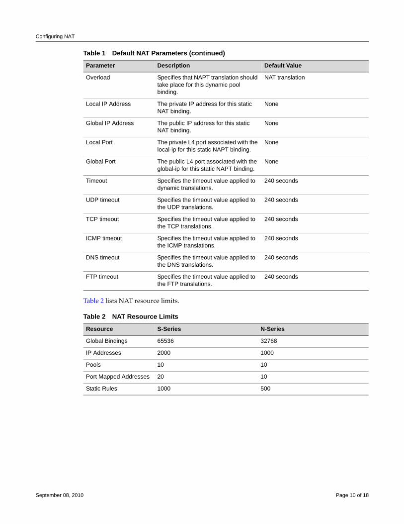
Configuring NAT
Table 2 lists NAT resource limits.
Overload Specifies that NAPT translation should take place for this dynamic pool binding.
NAT translation
Local IP Address The private IP address for this static NAT binding.
None
Global IP Address The public IP address for this static NAT binding.
None
Local Port The private L4 port associated with the local-ip for this static NAPT binding.
None
Global Port The public L4 port associated with the global-ip for this static NAPT binding.
None
Timeout Specifies the timeout value applied to dynamic translations.
240 seconds
UDP timeout Specifies the timeout value applied to the UDP translations.
240 seconds
TCP timeout Specifies the timeout value applied to the TCP translations.
240 seconds
ICMP timeout Specifies the timeout value applied to the ICMP translations.
240 seconds
DNS timeout Specifies the timeout value applied to the DNS translations.
240 seconds
FTP timeout Specifies the timeout value applied to the FTP translations.
240 seconds
Table 2 NAT Resource Limits
Resource S-Series N-Series
Global Bindings 65536 32768
IP Addresses 2000 1000
Pools 10 10
Port Mapped Addresses 20 10
Static Rules 1000 500
Table 1 Default NAT Parameters (continued)
Parameter Description Default Value
September 08, 2010 Page 10 of 18
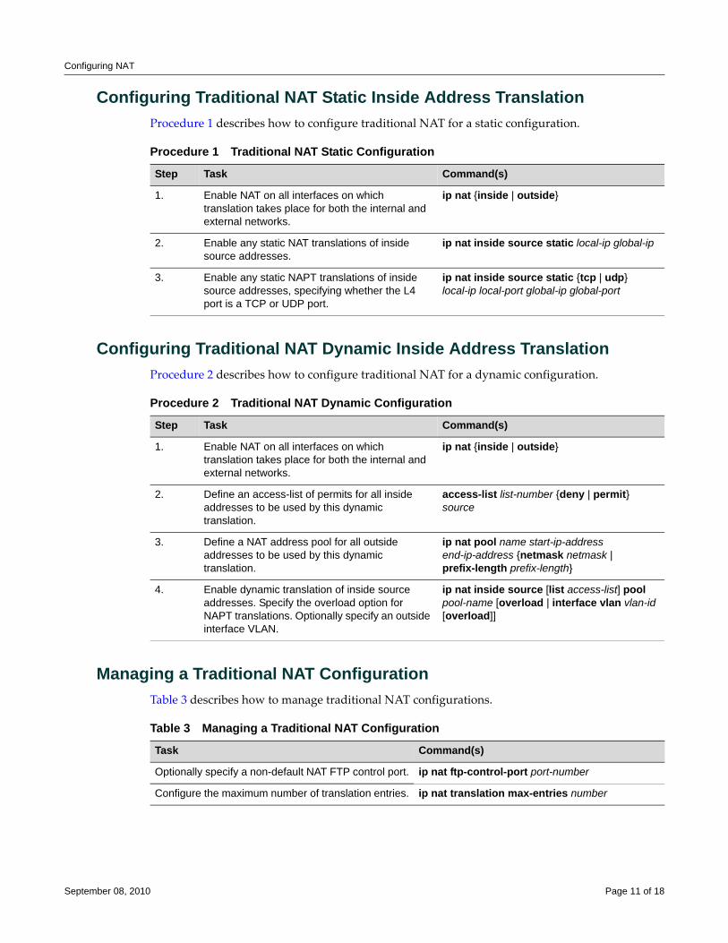
Configuring NAT
Configuring Traditional NAT Static Inside Address TranslationProcedure 1 describes how to configure traditional NAT for a static configuration.
Configuring Traditional NAT Dynamic Inside Address TranslationProcedure 2 describes how to configure traditional NAT for a dynamic configuration.
Managing a Traditional NAT ConfigurationTable 3 describes how to manage traditional NAT configurations.
Procedure 1 Traditional NAT Static Configuration
Step Task Command(s)
1. Enable NAT on all interfaces on which translation takes place for both the internal and external networks.
ip nat {inside | outside}
2. Enable any static NAT translations of inside source addresses.
ip nat inside source static local-ip global-ip
3. Enable any static NAPT translations of inside source addresses, specifying whether the L4 port is a TCP or UDP port.
ip nat inside source static {tcp | udp} local-ip local-port global-ip global-port
Procedure 2 Traditional NAT Dynamic Configuration
Step Task Command(s)
1. Enable NAT on all interfaces on which translation takes place for both the internal and external networks.
ip nat {inside | outside}
2. Define an access-list of permits for all inside addresses to be used by this dynamic translation.
access-list list-number {deny | permit} source
3. Define a NAT address pool for all outside addresses to be used by this dynamic translation.
ip nat pool name start-ip-address end-ip-address {netmask netmask | prefix-length prefix-length}
4. Enable dynamic translation of inside source addresses. Specify the overload option for NAPT translations. Optionally specify an outside interface VLAN.
ip nat inside source [list access-list] pool pool-name [overload | interface vlan vlan-id [overload]]
Table 3 Managing a Traditional NAT Configuration
Task Command(s)
Optionally specify a non-default NAT FTP control port. ip nat ftp-control-port port-number
Configure the maximum number of translation entries. ip nat translation max-entries number
September 08, 2010 Page 11 of 18
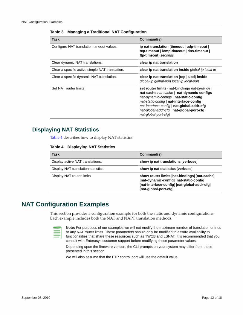
NAT Configuration Examples
Displaying NAT StatisticsTable 4 describes how to display NAT statistics.
NAT Configuration ExamplesThis section provides a configuration example for both the static and dynamic configurations. Each example includes both the NAT and NAPT translation methods.
Configure NAT translation timeout values. ip nat translation {timeout | udp-timeout | tcp-timeout | icmp-timeout | dns-timeout | ftp-timeout} seconds
Clear dynamic NAT translations. clear ip nat translation
Clear a specific active simple NAT translation. clear ip nat translation inside global-ip local-ip
Clear a specific dynamic NAT translation. clear ip nat translation {tcp | upd} inside global-ip global-port local-ip local-port
Set NAT router limits set router limits {nat-bindings nat-bindings | nat-cache nat-cache | nat-dynamic-configs nat-dynamic-configs | nat-static-config nat-static-config | nat-interface-config nat-interface-config | nat-global-addr-cfg nat-global-addr-cfg | nat-global-port-cfg nat-global-port-cfg}
Table 3 Managing a Traditional NAT Configuration
Task Command(s)
Table 4 Displaying NAT Statistics
Task Command(s)
Display active NAT translations. show ip nat translations [verbose]
Display NAT translation statistics. show ip nat statistics [verbose]
Display NAT router limits show router limits [nat-bindings] [nat-cache] [nat-dynamic-config] [nat-static-config] [nat-interface-config] [nat-global-addr-cfg] [nat-global-port-cfg]
Note: For purposes of our examples we will not modify the maximum number of translation entries or any NAT router limits. These parameters should only be modified to assure availability to functionalities that share these resources such as TWCB and LSNAT. It is recommended that you consult with Enterasys customer support before modifying these parameter values.
Depending upon the firmware version, the CLI prompts on your system may differ from those presented in this section.
We will also assume that the FTP control port will use the default value.
September 08, 2010 Page 12 of 18
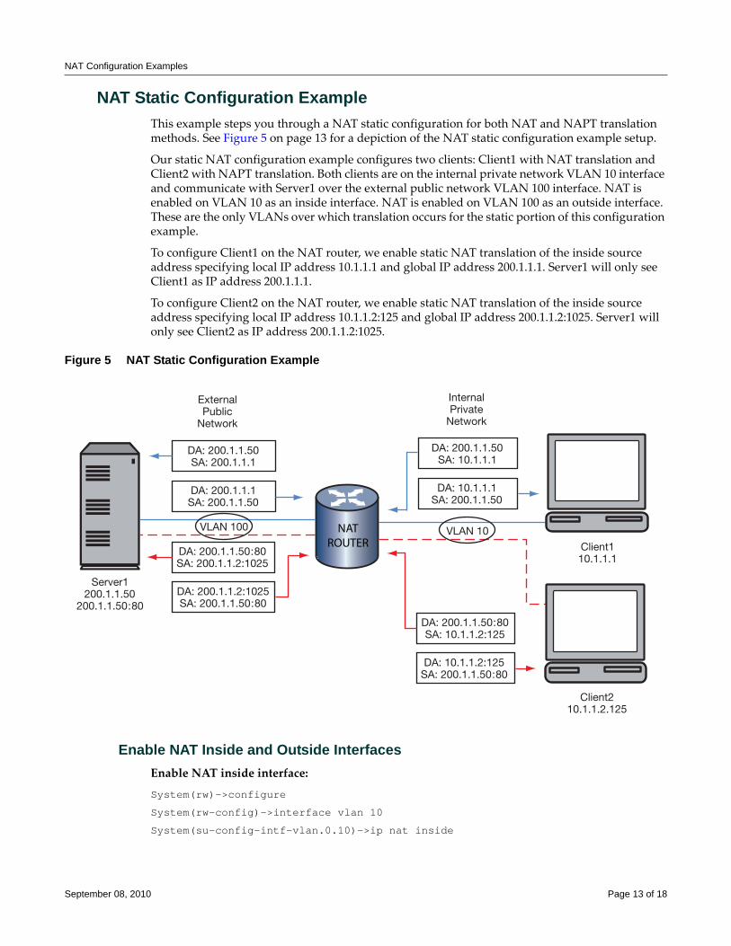
NAT Configuration Examples
NAT Static Configuration ExampleThis example steps you through a NAT static configuration for both NAT and NAPT translation methods. See Figure 5 on page 13 for a depiction of the NAT static configuration example setup.
Our static NAT configuration example configures two clients: Client1 with NAT translation and Client2 with NAPT translation. Both clients are on the internal private network VLAN 10 interface and communicate with Server1 over the external public network VLAN 100 interface. NAT is enabled on VLAN 10 as an inside interface. NAT is enabled on VLAN 100 as an outside interface. These are the only VLANs over which translation occurs for the static portion of this configuration example.
To configure Client1 on the NAT router, we enable static NAT translation of the inside source address specifying local IP address 10.1.1.1 and global IP address 200.1.1.1. Server1 will only see Client1 as IP address 200.1.1.1.
To configure Client2 on the NAT router, we enable static NAT translation of the inside source address specifying local IP address 10.1.1.2:125 and global IP address 200.1.1.2:1025. Server1 will only see Client2 as IP address 200.1.1.2:1025.
Figure 5 NAT Static Configuration Example
Enable NAT Inside and Outside InterfacesEnable NAT inside interface:
System(rw)->configure
System(rw-config)->interface vlan 10
System(su-config-intf-vlan.0.10)->ip nat inside
Server1200.1.1.50
200.1.1.50:80
NATROUTER
DA: 200.1.1.50:80SA: 200.1.1.2:1025
DA: 200.1.1.2:1025SA: 200.1.1.50:80
DA: 200.1.1.50:80SA: 10.1.1.2:125
DA: 10.1.1.2:125SA: 200.1.1.50:80
Client110.1.1.1
DA: 200.1.1.50SA: 200.1.1.1
VLAN 100 VLAN 10
ExternalPublic
Network
InternalPrivate
Network
DA: 200.1.1.1SA: 200.1.1.50
DA: 200.1.1.50SA: 10.1.1.1
DA: 10.1.1.1SA: 200.1.1.50
Client210.1.1.2.125
September 08, 2010 Page 13 of 18
NAT Configuration Examples
System(su-config-intf-vlan.0.10)->exit
System(rw-config)->
Enable NAT outside interface:
System(rw-config)->interface vlan 100
System(su-config-intf-vlan.0.100)->ip nat outside
System(su-config-intf-vlan.0.100)->exit
System(rw-config)->
Enable Static Translation of Inside Source AddressesEnable the NAT static translation of the inside source address:
System(rw-config)->ip nat inside source static 10.1.1.1 200.1.1.1
Enable the NAPT static translation of the inside source address:
System(rw-config)->ip nat inside source static tcp 10.1.1.2:125 200.1.1.2:1025
NAT Dynamic Configuration ExampleThis example steps you through a NAT Dynamic Configuration for both NAT and NAPT translation methods. See Figure 6 on page 15 for a depiction of the example setup.
Our dynamic NAT configuration example configures four clients: Client1 and Client2 with NAT translation and Client3 and Client4 with NAPT translation. The two NAT clients are on the internal private network VLAN 10 interface and communicate with Server1 over the external public network VLAN 100 interface. The two NAPT clients are on the internal private network VLAN 20 and communicate with Server1 over the external public network VLAN 200 interface. NAT is enabled on VLAN 10 and VLAN 20 as inside interfaces. NAT is enabled on VLAN 100 and VLAN 200 as outside interfaces. These are the only VLANs over which translation occurs for the dynamic portion of this configuration example.
To configure Client1 and Client2 for dynamic NAT translation on the NAT router, we define access‐list 1 to permit the local IP addresses 10.1.1.1 and 10.1.1.2. We then configure the NAT translation NAT pool natpool with the global address range of 200.1.1.1 to 200.1.1.2. We then enable dynamic translation of inside addresses associating access‐list 1 with the NAT pool natpool.
September 08, 2010 Page 14 of 18
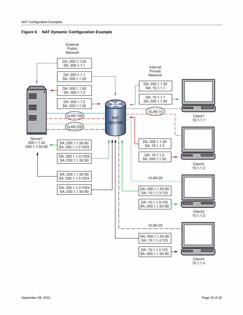
NAT Configuration Examples
Figure 6 NAT Dynamic Configuration Example
Server1200.1.1.50
200.1.1.50:80
NATROUTER
DA: 200.1.1.50:80SA: 200.1.1.3:1025
DA: 200.1.1.3:1025SA: 200.1.1.50:80
DA: 200.1.1.50SA: 10.1.1.2
DA: 10.1.1.2SA: 200.1.1.50
Client110.1.1.1
DA: 200.1.1.50SA: 200.1.1.2
VLAN 10
VLAN 20
InternalPrivate
Network
DA: 200.1.1.2SA: 200.1.1.50
DA: 200.1.1.50SA: 200.1.1.1
ExternalPublic
Network
DA: 200.1.1.1SA: 200.1.1.50
DA: 200.1.1.50SA: 10.1.1.1
DA: 10.1.1.1SA: 200.1.1.50
Client210.1.1.2
Client310.1.1.3
DA: 200.1.1.50:80SA: 10.1.1.3:125
DA: 10.1.1.3:125SA: 200.1.1.50:80
VLAN 100
VLAN 200
VLAN 20
Client410.1.1.4
DA: 200.1.1.50:80SA: 10.1.1.4:125
DA: 10.1.1.4:125SA: 200.1.1.50:80
DA: 200.1.1.50:80SA: 200.1.1.3:1024
DA: 200.1.1.3:1024SA: 200.1.1.50:80
September 08, 2010 Page 15 of 18
NAT Configuration Examples
To configure Client3 and Client4 for dynamic NAPT translation on the NAT router, we define access‐list 2 to permit the local IP addresses 10.1.1.3 and 10.1.1.4. We then configure NAT pool dynamicpool with a global range of 200.1.1.3 to 200.1.1.3. We then enable dynamic translation of inside addresses for overload associating access‐list 2 with the NAT pool naptpool.
Enable NAT Inside and Outside InterfacesEnable NAT inside interface:
System(rw)->configure
System(rw-config)->interface vlan 10
System(su-config-intf-vlan.0.10)->ip nat inside
System(su-config-intf-vlan.0.10)->exit
System(rw-config)->interface vlan 20
System(su-config-intf-vlan.0.20)->ip nat inside
System(su-config-intf-vlan.0.20)->exit
System(rw-config)->
Enable NAT outside interface:
System(rw-config)->interface vlan 100
System(su-config-intf-vlan.0.100)->ip nat outside
System(su-config-intf-vlan.0.100)->exit
System(rw-config)->interface vlan 200
System(su-config-intf-vlan.0.200)->ip nat outside
System(su-config-intf-vlan.0.200)->exit
System(rw-config)->
Define Inside Address Access-ListsDefine inside address access‐list 1 for NAT clients:
System(rw-config)->access-list 1 permit host 10.1.1.1
System(rw-config)->access-list 1 permit host 10.1.1.2
System(rw-config)->
Define inside address access‐list 2 for NAPT clients:
System(rw-config)->access-list 2 permit host 10.1.1.3
System(rw-config)->access-list 2 permit host 10.1.1.4
System(rw-config)->
September 08, 2010 Page 16 of 18
Terms and Definitions
Define the NAT Pools for Global AddressesDefine the NAT Pool for the NAT clients:
System(rw-config)->ip nat pool natpool 200.1.1.1 200.1.1.2 netmask 255.255.255.0
Define the NAT Pool for the NAPT clients:
System(rw-config)->ip nat pool naptpool 200.1.1.3 200.1.1.3 netmask 255.255.255.0
System(rw-config)->
Enable Dynamic Translation of Inside Source AddressesEnable the NAT dynamic translation of the inside source address:
System(rw-config)->ip nat inside source list 1 pool natpool
Enable the NAPT dynamic translation of the inside source address:
System(rw-config)->ip nat inside source list 2 pool naptpool overload
This completes the NAT configuration example.
Terms and DefinitionsTable 5 lists terms and definitions used in this NAT configuration discussion.
Table 5 NAT Configuration Terms and Definitions Term Definition
Basic NAT Refers to Network Address Translation (NAT) only.
Dynamic Address Binding
Provides a binding based upon an internal algorithm between an address from an access-list of local addresses to an address from a pool of global addresses for NAT and TCP/UDP port number translations for NAPT.
Inside (private) address
An IP address internal to the network only reachable by the external network by translation.
NAT Address Pool A grouping of global addresses used by both NAT and NAPT dynamic address binding.
Network Address Port Translation (NAPT)
Provides a mechanism to connect a realm with private addresses to an external realm with globally unique registered addresses by mapping many network addresses, along with their associated TCP/UDP ports into a single network address and its associated TCP/UDP ports.
Network Address Translation (NAT)
Provides a mechanism to connect an internal realm with private addresses to an external realm with globally unique registered addresses by mapping IP addresses from one group to another, transparent to the end user.
Outside (public) address
A registered global IP address external to the private network that the inside address is translated to.
Static Address Binding
Provides a one-to-one binding between local addresses to global addresses for NAT and TCP/UDP port number translations for NAPT.
Traditional NAT Refers to both NAT and NAPT.
September 08, 2010 Page 17 of 18
Enterasys Networks reserves the right to make changes in specifications and other information contained in this document and its web site without prior notice. The reader should in all cases consult Enterasys Networks to determine whether any such changes have been made.
The hardware, firmware, or software described in this document is subject to change without notice.
IN NO EVENT SHALL ENTERASYS NETWORKS BE LIABLE FOR ANY INCIDENTAL, INDIRECT, SPECIAL, OR CONSEQUENTIAL DAMAGES WHATSOEVER (INCLUDING BUT NOT LIMITED TO LOST PROFITS) ARISING OUT OF OR RELATED TO THIS DOCUMENT, WEB SITE, OR THE INFORMATION CONTAINED IN THEM, EVEN IF ENTERASYS NETWORKS HAS BEEN ADVISED OF, KNEW OF, OR SHOULD HAVE KNOWN OF, THE POSSIBILITY OF SUCH DAMAGES.
Enterasys Networks, Inc.50 Minuteman RoadAndover, MA 01810
© 2010 Enterasys Networks, Inc. All rights reserved.
ENTERASYS, ENTERASYS NETWORKS, ENTERASYS MATRIX, ENTERASYS S‐SERIES and any logos associated therewith, are trademarks or registered trademarks of Enterasys Networks, Inc., in the United States and other countries. For a complete list of Enterasys trademarks, see http://www.enterasys.com/company/trademarks.aspx.
All other product names mentioned in this manual may be trademarks or registered trademarks of their respective companies.
Revision History
Date Description
09/24/2008 New document
02/12/2009 In ip nat inside source context made clear that VLAN option was for an outside VLAN.
04/16/2009 Input an advanced routing license notice that includes the 256 MB requirement on all modules statement.
09/08/2010 Updated for S-Series. Added new resource-limits table.
Configuring Neighbor Discovery
This document provides information about configuring and monitoring neighbor discovery on Enterasys Matrix® N‐Series, Enterasys SecureStack™, D‐Series, G‐Series, and I‐Series devices.
What is Neighbor Discovery?Neighbor discovery is the Layer 2 process in which a device identifies and advertises itself to its directly connected neighbors. Enterasys devices support the following neighbor discovery protocols:
• Link Layer Discovery Protocol (LLDP) and its extension, LLDP‐MED, which is the IEEE 802.1AB standard for neighbor discovery
• Enterasys Discovery Protocol, for discovering Enterasys devices
• Cisco Discovery Protocol, for discovering Cisco devices
Why Would I Use Neighbor Discovery in My Network?Neighbor discovery is useful for the following:
• Determining an accurate physical network topology
• Creating an inventory of network devices
• Troubleshooting the network
Note: For information on Enterasys Matrix X-Series support, refer to the Enterasys Matrix X Secure Core Router Configuration Guide.
For information about... Refer to page...
What is Neighbor Discovery? 1
Why Would I Use Neighbor Discovery in My Network? 1
How Do I Implement Neighbor Discovery? 2
Understanding Neighbor Discovery 2
Configuring LLDP 7
Note: Currently, LLDP is not supported on Enterasys I-Series devices.
October 15, 2008 Page 1 of 14
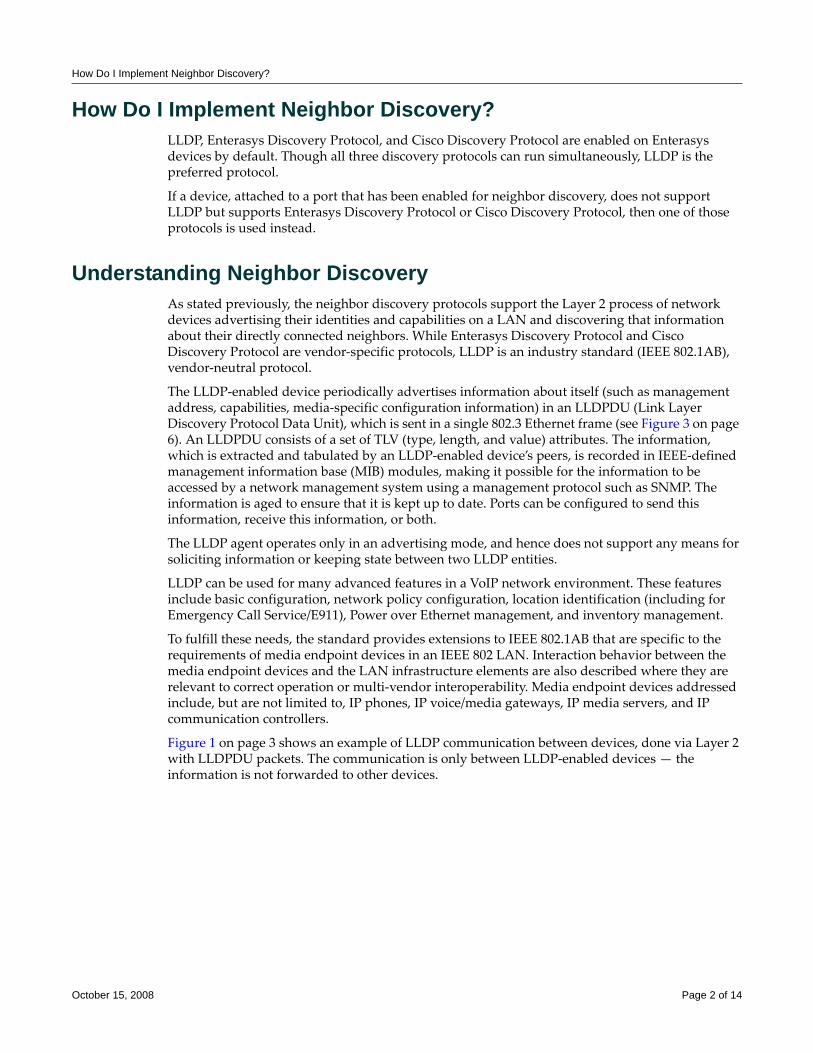
How Do I Implement Neighbor Discovery?
How Do I Implement Neighbor Discovery?LLDP, Enterasys Discovery Protocol, and Cisco Discovery Protocol are enabled on Enterasys devices by default. Though all three discovery protocols can run simultaneously, LLDP is the preferred protocol.
If a device, attached to a port that has been enabled for neighbor discovery, does not support LLDP but supports Enterasys Discovery Protocol or Cisco Discovery Protocol, then one of those protocols is used instead.
Understanding Neighbor DiscoveryAs stated previously, the neighbor discovery protocols support the Layer 2 process of network devices advertising their identities and capabilities on a LAN and discovering that information about their directly connected neighbors. While Enterasys Discovery Protocol and Cisco Discovery Protocol are vendor‐specific protocols, LLDP is an industry standard (IEEE 802.1AB), vendor‐neutral protocol.
The LLDP‐enabled device periodically advertises information about itself (such as management address, capabilities, media‐specific configuration information) in an LLDPDU (Link Layer Discovery Protocol Data Unit), which is sent in a single 802.3 Ethernet frame (see Figure 3 on page 6). An LLDPDU consists of a set of TLV (type, length, and value) attributes. The information, which is extracted and tabulated by an LLDP‐enabled device’s peers, is recorded in IEEE‐defined management information base (MIB) modules, making it possible for the information to be accessed by a network management system using a management protocol such as SNMP. The information is aged to ensure that it is kept up to date. Ports can be configured to send this information, receive this information, or both.
The LLDP agent operates only in an advertising mode, and hence does not support any means for soliciting information or keeping state between two LLDP entities.
LLDP can be used for many advanced features in a VoIP network environment. These features include basic configuration, network policy configuration, location identification (including for Emergency Call Service/E911), Power over Ethernet management, and inventory management.
To fulfill these needs, the standard provides extensions to IEEE 802.1AB that are specific to the requirements of media endpoint devices in an IEEE 802 LAN. Interaction behavior between the media endpoint devices and the LAN infrastructure elements are also described where they are relevant to correct operation or multi‐vendor interoperability. Media endpoint devices addressed include, but are not limited to, IP phones, IP voice/media gateways, IP media servers, and IP communication controllers.
Figure 1 on page 3 shows an example of LLDP communication between devices, done via Layer 2 with LLDPDU packets. The communication is only between LLDP‐enabled devices — the information is not forwarded to other devices.
October 15, 2008 Page 2 of 14
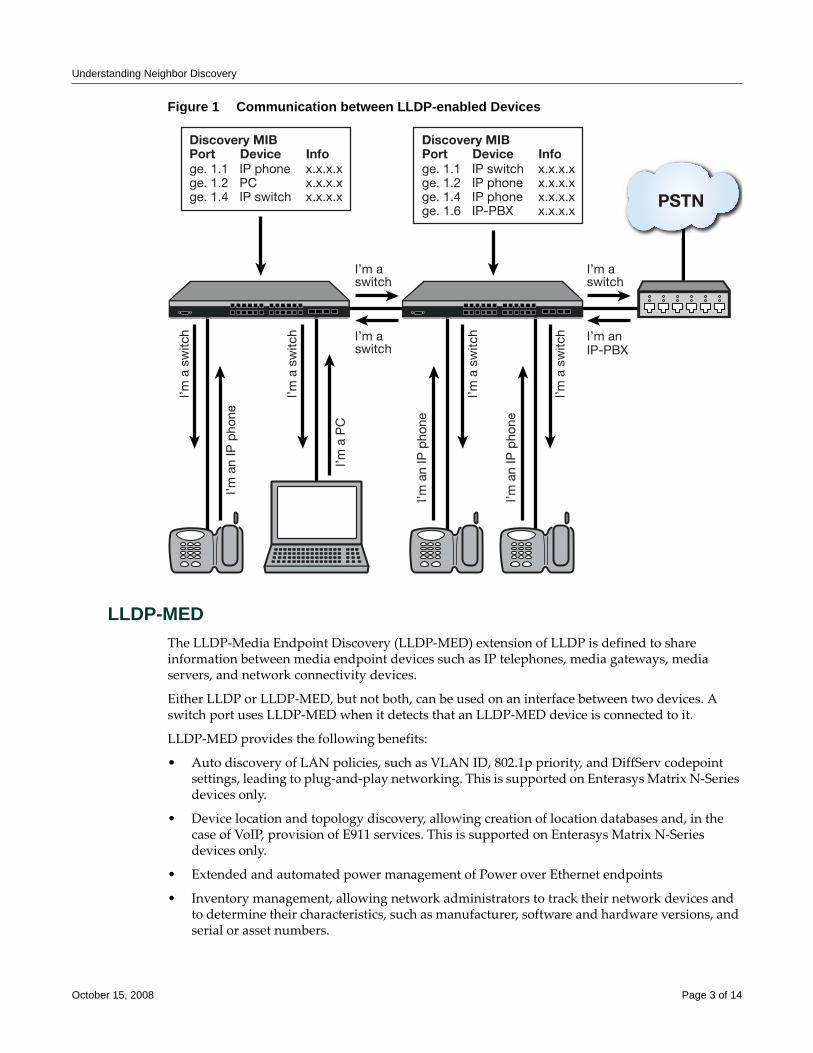
Understanding Neighbor Discovery
Figure 1 Communication between LLDP-enabled Devices
LLDP-MEDThe LLDP‐Media Endpoint Discovery (LLDP‐MED) extension of LLDP is defined to share information between media endpoint devices such as IP telephones, media gateways, media servers, and network connectivity devices.
Either LLDP or LLDP‐MED, but not both, can be used on an interface between two devices. A switch port uses LLDP‐MED when it detects that an LLDP‐MED device is connected to it.
LLDP‐MED provides the following benefits:
• Auto discovery of LAN policies, such as VLAN ID, 802.1p priority, and DiffServ codepoint settings, leading to plug‐and‐play networking. This is supported on Enterasys Matrix N‐Series devices only.
• Device location and topology discovery, allowing creation of location databases and, in the case of VoIP, provision of E911 services. This is supported on Enterasys Matrix N‐Series devices only.
• Extended and automated power management of Power over Ethernet endpoints
• Inventory management, allowing network administrators to track their network devices and to determine their characteristics, such as manufacturer, software and hardware versions, and serial or asset numbers.
I’m aswitch
I’m aswitch
I’m a
sw
itch
I’m a
sw
itch
I’m a
sw
itch
I’m a
n IP
pho
ne
I’m a
n IP
pho
ne
I’m a
PC
I’m aswitch
I’m anIP-PBX
I’m a
n IP
pho
ne
I’m a
sw
itch
PSTN
Discovery MIBPort Device Infoge. 1.1ge. 1.2ge. 1.4
IP phonePCIP switch
x.x.x.xx.x.x.xx.x.x.x
Discovery MIBPort Device Infoge. 1.1ge. 1.2ge. 1.4ge. 1.6
IP switchIP phoneIP phoneIP-PBX
x.x.x.xx.x.x.xx.x.x.xx.x.x.x
October 15, 2008 Page 3 of 14
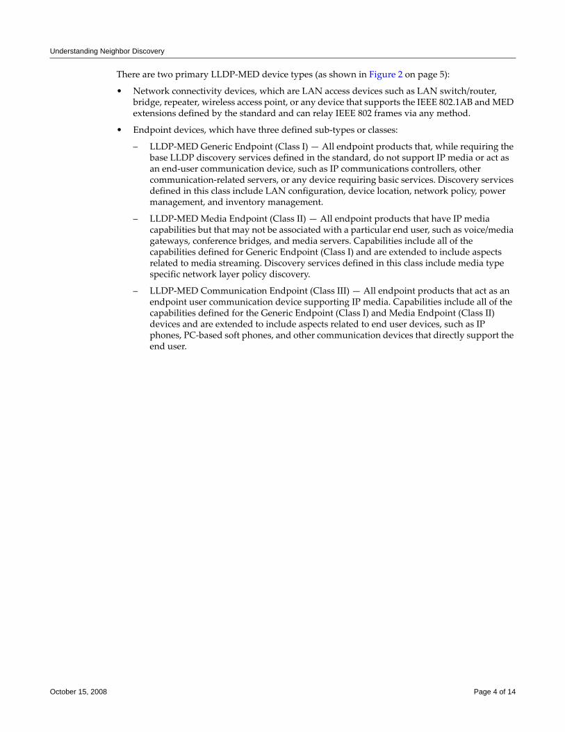
Understanding Neighbor Discovery
There are two primary LLDP‐MED device types (as shown in Figure 2 on page 5):
• Network connectivity devices, which are LAN access devices such as LAN switch/router, bridge, repeater, wireless access point, or any device that supports the IEEE 802.1AB and MED extensions defined by the standard and can relay IEEE 802 frames via any method.
• Endpoint devices, which have three defined sub‐types or classes:
– LLDP‐MED Generic Endpoint (Class I) — All endpoint products that, while requiring the base LLDP discovery services defined in the standard, do not support IP media or act as an end‐user communication device, such as IP communications controllers, other communication‐related servers, or any device requiring basic services. Discovery services defined in this class include LAN configuration, device location, network policy, power management, and inventory management.
– LLDP‐MED Media Endpoint (Class II) — All endpoint products that have IP media capabilities but that may not be associated with a particular end user, such as voice/media gateways, conference bridges, and media servers. Capabilities include all of the capabilities defined for Generic Endpoint (Class I) and are extended to include aspects related to media streaming. Discovery services defined in this class include media type specific network layer policy discovery.
– LLDP‐MED Communication Endpoint (Class III) — All endpoint products that act as an endpoint user communication device supporting IP media. Capabilities include all of the capabilities defined for the Generic Endpoint (Class I) and Media Endpoint (Class II) devices and are extended to include aspects related to end user devices, such as IP phones, PC‐based soft phones, and other communication devices that directly support the end user.
October 15, 2008 Page 4 of 14
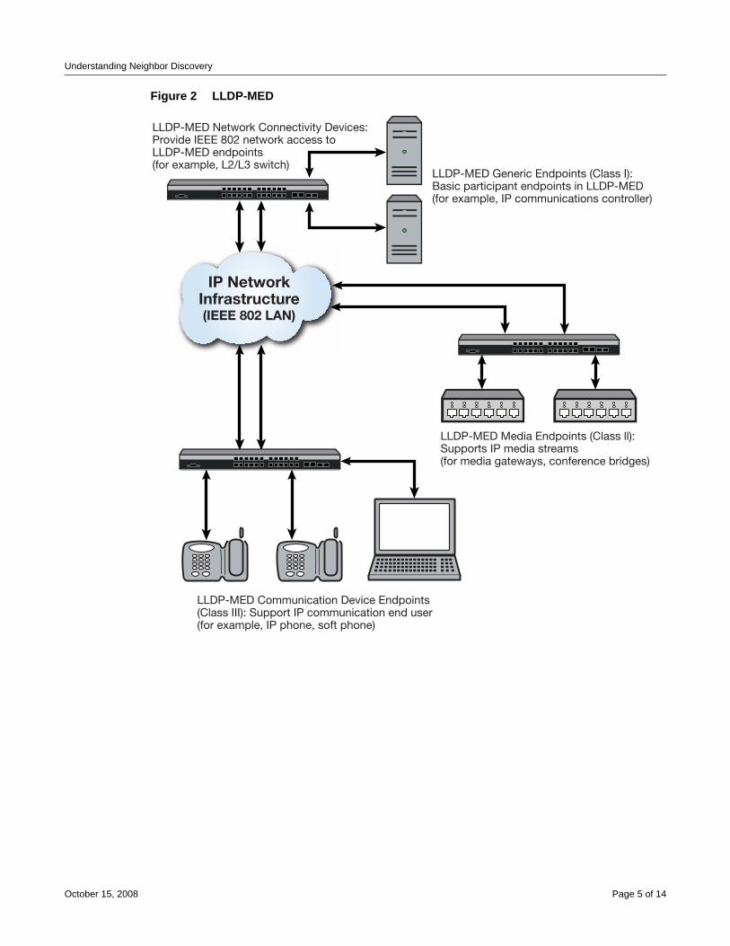
Understanding Neighbor Discovery
Figure 2 LLDP-MED
IP NetworkInfrastructure(IEEE 802 LAN)
LLDP-MED Communication Device Endpoints(Class III): Support IP communication end user(for example, IP phone, soft phone)
LLDP-MED Network Connectivity Devices:Provide IEEE 802 network access toLLDP-MED endpoints(for example, L2/L3 switch)
LLDP-MED Generic Endpoints (Class I):Basic participant endpoints in LLDP-MED(for example, IP communications controller)
LLDP-MED Media Endpoints (Class ll):Supports IP media streams(for media gateways, conference bridges)
October 15, 2008 Page 5 of 14
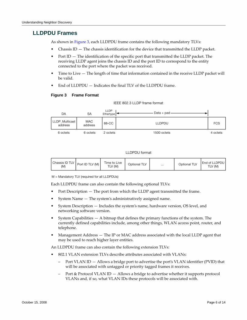
Understanding Neighbor Discovery
LLDPDU FramesAs shown in Figure 3, each LLDPDU frame contains the following mandatory TLVs:
• Chassis ID — The chassis identification for the device that transmitted the LLDP packet.
• Port ID — The identification of the specific port that transmitted the LLDP packet. The receiving LLDP agent joins the chassis ID and the port ID to correspond to the entity connected to the port where the packet was received.
• Time to Live — The length of time that information contained in the receive LLDP packet will be valid.
• End of LLDPDU — Indicates the final TLV of the LLDPDU frame.
Figure 3 Frame Format
Each LLDPDU frame can also contain the following optional TLVs:
• Port Description — The port from which the LLDP agent transmitted the frame.
• System Name — The system’s administratively assigned name.
• System Description — Includes the system’s name, hardware version, OS level, and networking software version.
• System Capabilities — A bitmap that defines the primary functions of the system. The currently defined capabilities include, among other things, WLAN access point, router, and telephone.
• Management Address — The IP or MAC address associated with the local LLDP agent that may be used to reach higher layer entities.
An LLDPDU frame can also contain the following extension TLVs:
• 802.1 VLAN extension TLVs describe attributes associated with VLANs:
– Port VLAN ID — Allows a bridge port to advertise the port’s VLAN identifier (PVID) that will be associated with untagged or priority tagged frames it receives.
– Port & Protocol VLAN ID — Allows a bridge to advertise whether it supports protocol VLANs and, if so, what VLAN IDs these protocols will be associated with.
LLDP_Multicastaddress
Chassis ID TLV(M)
Time to LiveTLV (M)
End of LLDPDUTLV (M)
Port ID TLV (M) Optional TLV ... Optional TLV
MACaddress 88-CC LLDPDU FCS
6 octets
M = Mandatory TLV (required for all LLDPDUs)
DA SALLDP
Ethertype
6 octets 2 octets 1500 octets 4 octets
Data + pad
IEEE 802.3 LLDP frame format
LLDPDU format
October 15, 2008 Page 6 of 14
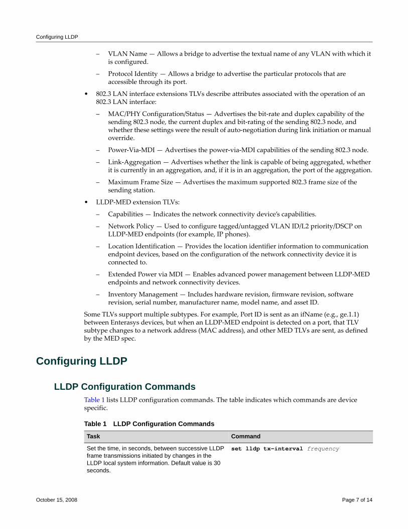
Configuring LLDP
– VLAN Name — Allows a bridge to advertise the textual name of any VLAN with which it is configured.
– Protocol Identity — Allows a bridge to advertise the particular protocols that are accessible through its port.
• 802.3 LAN interface extensions TLVs describe attributes associated with the operation of an 802.3 LAN interface:
– MAC/PHY Configuration/Status — Advertises the bit‐rate and duplex capability of the sending 802.3 node, the current duplex and bit‐rating of the sending 802.3 node, and whether these settings were the result of auto‐negotiation during link initiation or manual override.
– Power‐Via‐MDI — Advertises the power‐via‐MDI capabilities of the sending 802.3 node.
– Link‐Aggregation — Advertises whether the link is capable of being aggregated, whether it is currently in an aggregation, and, if it is in an aggregation, the port of the aggregation.
– Maximum Frame Size — Advertises the maximum supported 802.3 frame size of the sending station.
• LLDP‐MED extension TLVs:
– Capabilities — Indicates the network connectivity device’s capabilities.
– Network Policy — Used to configure tagged/untagged VLAN ID/L2 priority/DSCP on LLDP‐MED endpoints (for example, IP phones).
– Location Identification — Provides the location identifier information to communication endpoint devices, based on the configuration of the network connectivity device it is connected to.
– Extended Power via MDI — Enables advanced power management between LLDP‐MED endpoints and network connectivity devices.
– Inventory Management — Includes hardware revision, firmware revision, software revision, serial number, manufacturer name, model name, and asset ID.
Some TLVs support multiple subtypes. For example, Port ID is sent as an ifName (e.g., ge.1.1) between Enterasys devices, but when an LLDP‐MED endpoint is detected on a port, that TLV subtype changes to a network address (MAC address), and other MED TLVs are sent, as defined by the MED spec.
Configuring LLDP
LLDP Configuration CommandsTable 1 lists LLDP configuration commands. The table indicates which commands are device specific.
Table 1 LLDP Configuration Commands
Task Command
Set the time, in seconds, between successive LLDP frame transmissions initiated by changes in the LLDP local system information. Default value is 30 seconds.
set lldp tx-interval frequency
October 15, 2008 Page 7 of 14
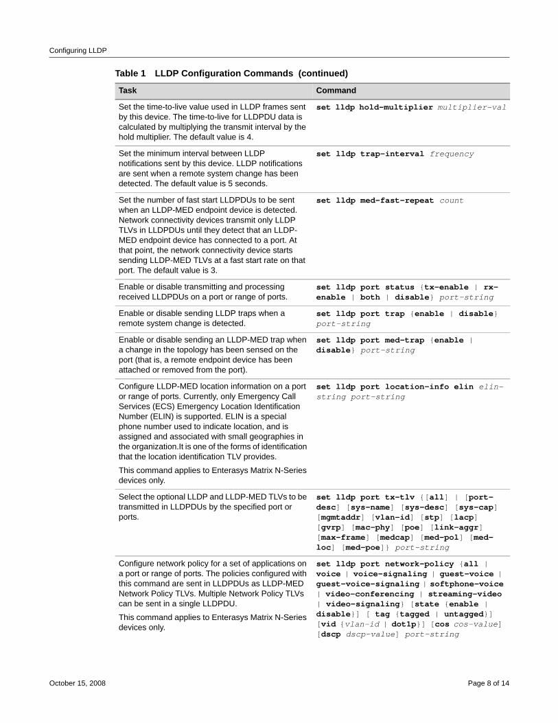
Configuring LLDP
Set the time-to-live value used in LLDP frames sent by this device. The time-to-live for LLDPDU data is calculated by multiplying the transmit interval by the hold multiplier. The default value is 4.
set lldp hold-multiplier multiplier-val
Set the minimum interval between LLDP notifications sent by this device. LLDP notifications are sent when a remote system change has been detected. The default value is 5 seconds.
set lldp trap-interval frequency
Set the number of fast start LLDPDUs to be sent when an LLDP-MED endpoint device is detected. Network connectivity devices transmit only LLDP TLVs in LLDPDUs until they detect that an LLDP-MED endpoint device has connected to a port. At that point, the network connectivity device starts sending LLDP-MED TLVs at a fast start rate on that port. The default value is 3.
set lldp med-fast-repeat count
Enable or disable transmitting and processing received LLDPDUs on a port or range of ports.
set lldp port status {tx-enable | rx-enable | both | disable} port-string
Enable or disable sending LLDP traps when a remote system change is detected.
set lldp port trap {enable | disable} port-string
Enable or disable sending an LLDP-MED trap when a change in the topology has been sensed on the port (that is, a remote endpoint device has been attached or removed from the port).
set lldp port med-trap {enable | disable} port-string
Configure LLDP-MED location information on a port or range of ports. Currently, only Emergency Call Services (ECS) Emergency Location Identification Number (ELIN) is supported. ELIN is a special phone number used to indicate location, and is assigned and associated with small geographies in the organization.It is one of the forms of identification that the location identification TLV provides.
This command applies to Enterasys Matrix N-Series devices only.
set lldp port location-info elin elin-string port-string
Select the optional LLDP and LLDP-MED TLVs to be transmitted in LLDPDUs by the specified port or ports.
set lldp port tx-tlv {[all] | [port-desc] [sys-name] [sys-desc] [sys-cap] [mgmtaddr] [vlan-id] [stp] [lacp] [gvrp] [mac-phy] [poe] [link-aggr] [max-frame] [medcap] [med-pol] [med-loc] [med-poe]} port-string
Configure network policy for a set of applications on a port or range of ports. The policies configured with this command are sent in LLDPDUs as LLDP-MED Network Policy TLVs. Multiple Network Policy TLVs can be sent in a single LLDPDU.
This command applies to Enterasys Matrix N-Series devices only.
set lldp port network-policy {all | voice | voice-signaling | guest-voice | guest-voice-signaling | softphone-voice | video-conferencing | streaming-video | video-signaling} [state {enable | disable}] [ tag {tagged | untagged}] [vid {vlan-id | dot1p}] [cos cos-value] [dscp dscp-value] port-string
Table 1 LLDP Configuration Commands (continued)
Task Command
October 15, 2008 Page 8 of 14
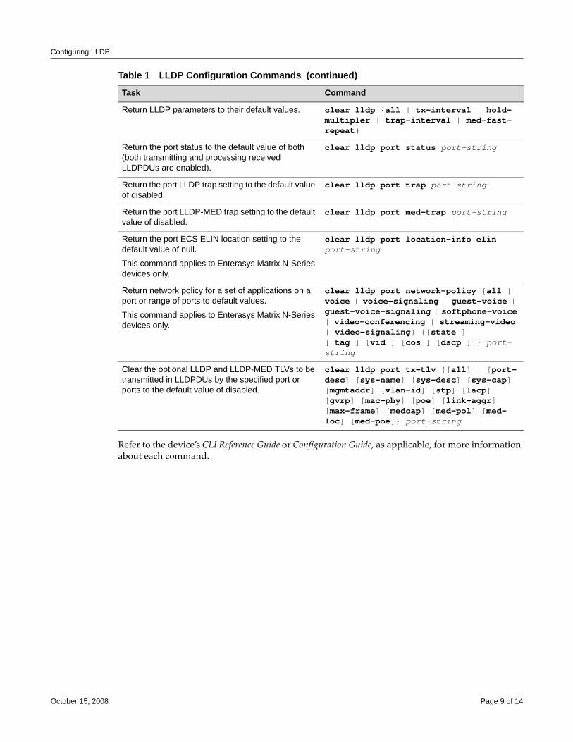
Configuring LLDP
Refer to the device’s CLI Reference Guide or Configuration Guide, as applicable, for more information about each command.
Return LLDP parameters to their default values. clear lldp {all | tx-interval | hold-multipler | trap-interval | med-fast-repeat}
Return the port status to the default value of both (both transmitting and processing received LLDPDUs are enabled).
clear lldp port status port-string
Return the port LLDP trap setting to the default value of disabled.
clear lldp port trap port-string
Return the port LLDP-MED trap setting to the default value of disabled.
clear lldp port med-trap port-string
Return the port ECS ELIN location setting to the default value of null.
This command applies to Enterasys Matrix N-Series devices only.
clear lldp port location-info elin port-string
Return network policy for a set of applications on a port or range of ports to default values.
This command applies to Enterasys Matrix N-Series devices only.
clear lldp port network-policy {all | voice | voice-signaling | guest-voice | guest-voice-signaling | softphone-voice | video-conferencing | streaming-video | video-signaling} {[state ] [ tag ] [vid ] [cos ] [dscp ] } port-string
Clear the optional LLDP and LLDP-MED TLVs to be transmitted in LLDPDUs by the specified port or ports to the default value of disabled.
clear lldp port tx-tlv {[all] | [port-desc] [sys-name] [sys-desc] [sys-cap] [mgmtaddr] [vlan-id] [stp] [lacp] [gvrp] [mac-phy] [poe] [link-aggr] [max-frame] [medcap] [med-pol] [med-loc] [med-poe]} port-string
Table 1 LLDP Configuration Commands (continued)
Task Command
October 15, 2008 Page 9 of 14
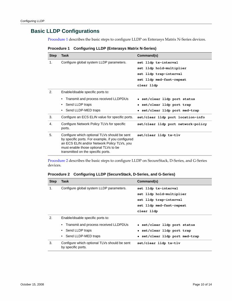
Configuring LLDP
Basic LLDP ConfigurationsProcedure 1 describes the basic steps to configure LLDP on Enterasys Matrix N‐Series devices.
Procedure 2 describes the basic steps to configure LLDP on SecureStack, D‐Series, and G‐Series devices.
Procedure 1 Configuring LLDP (Enterasys Matrix N-Series)
Step Task Command(s)
1. Configure global system LLDP parameters. set lldp tx-interval
set lldp hold-multiplier
set lldp trap-interval
set lldp med-fast-repeat
clear lldp
2. Enable/disable specific ports to:
• Transmit and process received LLDPDUs
• Send LLDP traps
• Send LLDP-MED traps
• set/clear lldp port status
• set/clear lldp port trap
• set/clear lldp port med-trap
3. Configure an ECS ELIN value for specific ports. set/clear lldp port location-info
4. Configure Network Policy TLVs for specific ports.
set/clear lldp port network-policy
5. Configure which optional TLVs should be sent by specific ports. For example, if you configured an ECS ELIN and/or Network Policy TLVs, you must enable those optional TLVs to be transmitted on the specific ports.
set/clear lldp tx-tlv
Procedure 2 Configuring LLDP (SecureStack, D-Series, and G-Series)
Step Task Command(s)
1. Configure global system LLDP parameters. set lldp tx-interval
set lldp hold-multiplier
set lldp trap-interval
set lldp med-fast-repeat
clear lldp
2. Enable/disable specific ports to:
• Transmit and process received LLDPDUs
• Send LLDP traps
• Send LLDP-MED traps
• set/clear lldp port status
• set/clear lldp port trap
• set/clear lldp port med-trap
3. Configure which optional TLVs should be sent by specific ports.
set/clear lldp tx-tlv
October 15, 2008 Page 10 of 14
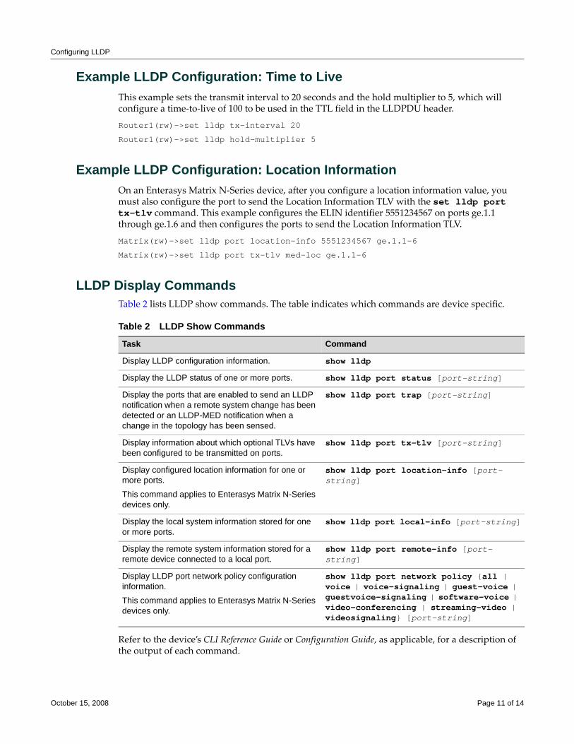
Configuring LLDP
Example LLDP Configuration: Time to LiveThis example sets the transmit interval to 20 seconds and the hold multiplier to 5, which will configure a time‐to‐live of 100 to be used in the TTL field in the LLDPDU header.
Router1(rw)->set lldp tx-interval 20
Router1(rw)->set lldp hold-multiplier 5
Example LLDP Configuration: Location InformationOn an Enterasys Matrix N‐Series device, after you configure a location information value, you must also configure the port to send the Location Information TLV with the set lldp port tx-tlv command. This example configures the ELIN identifier 5551234567 on ports ge.1.1 through ge.1.6 and then configures the ports to send the Location Information TLV.
Matrix(rw)->set lldp port location-info 5551234567 ge.1.1-6
Matrix(rw)->set lldp port tx-tlv med-loc ge.1.1-6
LLDP Display CommandsTable 2 lists LLDP show commands. The table indicates which commands are device specific.
Refer to the device’s CLI Reference Guide or Configuration Guide, as applicable, for a description of the output of each command.
Table 2 LLDP Show Commands
Task Command
Display LLDP configuration information. show lldp
Display the LLDP status of one or more ports. show lldp port status [port-string]
Display the ports that are enabled to send an LLDP notification when a remote system change has been detected or an LLDP-MED notification when a change in the topology has been sensed.
show lldp port trap [port-string]
Display information about which optional TLVs have been configured to be transmitted on ports.
show lldp port tx-tlv [port-string]
Display configured location information for one or more ports.
This command applies to Enterasys Matrix N-Series devices only.
show lldp port location-info [port-string]
Display the local system information stored for one or more ports.
show lldp port local-info [port-string]
Display the remote system information stored for a remote device connected to a local port.
show lldp port remote-info [port-string]
Display LLDP port network policy configuration information.
This command applies to Enterasys Matrix N-Series devices only.
show lldp port network policy {all | voice | voice-signaling | guest-voice | guestvoice-signaling | software-voice | video-conferencing | streaming-video | videosignaling} [port-string]
October 15, 2008 Page 11 of 14
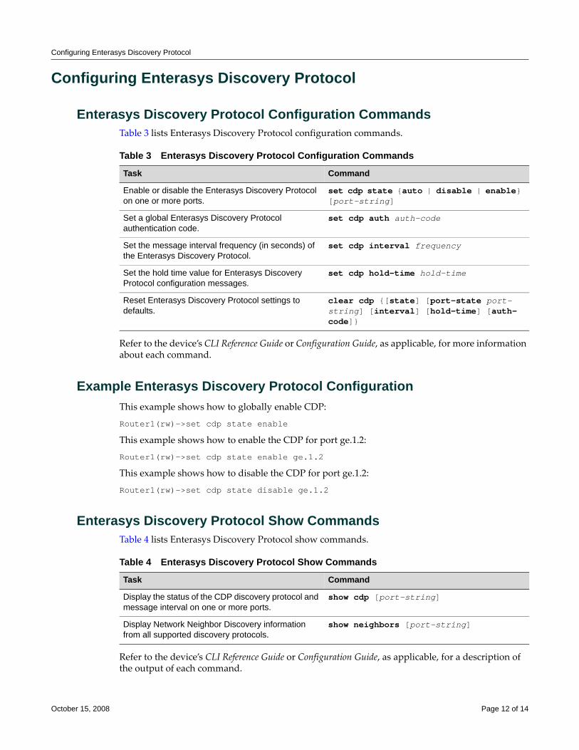
Configuring Enterasys Discovery Protocol
Configuring Enterasys Discovery Protocol
Enterasys Discovery Protocol Configuration CommandsTable 3 lists Enterasys Discovery Protocol configuration commands.
Refer to the device’s CLI Reference Guide or Configuration Guide, as applicable, for more information about each command.
Example Enterasys Discovery Protocol ConfigurationThis example shows how to globally enable CDP:
Router1(rw)->set cdp state enable
This example shows how to enable the CDP for port ge.1.2:
Router1(rw)->set cdp state enable ge.1.2
This example shows how to disable the CDP for port ge.1.2:
Router1(rw)->set cdp state disable ge.1.2
Enterasys Discovery Protocol Show CommandsTable 4 lists Enterasys Discovery Protocol show commands.
Refer to the device’s CLI Reference Guide or Configuration Guide, as applicable, for a description of the output of each command.
Table 3 Enterasys Discovery Protocol Configuration Commands
Task Command
Enable or disable the Enterasys Discovery Protocol on one or more ports.
set cdp state {auto | disable | enable} [port-string]
Set a global Enterasys Discovery Protocol authentication code.
set cdp auth auth-code
Set the message interval frequency (in seconds) of the Enterasys Discovery Protocol.
set cdp interval frequency
Set the hold time value for Enterasys Discovery Protocol configuration messages.
set cdp hold-time hold-time
Reset Enterasys Discovery Protocol settings to defaults.
clear cdp {[state] [port-state port-string] [interval] [hold-time] [auth-code]}
Table 4 Enterasys Discovery Protocol Show Commands
Task Command
Display the status of the CDP discovery protocol and message interval on one or more ports.
show cdp [port-string]
Display Network Neighbor Discovery information from all supported discovery protocols.
show neighbors [port-string]
October 15, 2008 Page 12 of 14
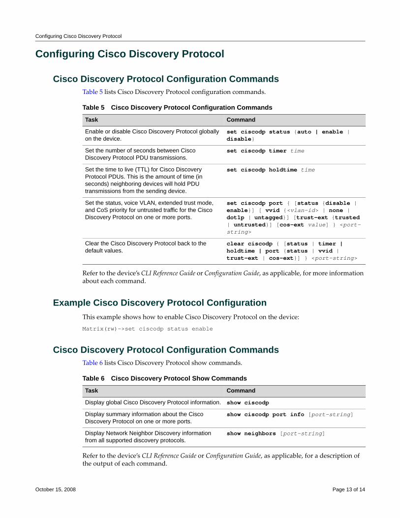
Configuring Cisco Discovery Protocol
Configuring Cisco Discovery Protocol
Cisco Discovery Protocol Configuration CommandsTable 5 lists Cisco Discovery Protocol configuration commands.
Refer to the device’s CLI Reference Guide or Configuration Guide, as applicable, for more information about each command.
Example Cisco Discovery Protocol ConfigurationThis example shows how to enable Cisco Discovery Protocol on the device:
Matrix(rw)->set ciscodp status enable
Cisco Discovery Protocol Configuration CommandsTable 6 lists Cisco Discovery Protocol show commands.
Refer to the device’s CLI Reference Guide or Configuration Guide, as applicable, for a description of the output of each command.
Table 5 Cisco Discovery Protocol Configuration Commands
Task Command
Enable or disable Cisco Discovery Protocol globally on the device.
set ciscodp status {auto | enable | disable}
Set the number of seconds between Cisco Discovery Protocol PDU transmissions.
set ciscodp timer time
Set the time to live (TTL) for Cisco Discovery Protocol PDUs. This is the amount of time (in seconds) neighboring devices will hold PDU transmissions from the sending device.
set ciscodp holdtime time
Set the status, voice VLAN, extended trust mode, and CoS priority for untrusted traffic for the Cisco Discovery Protocol on one or more ports.
set ciscodp port { [status {disable | enable}] [ vvid {<vlan-id> | none | dot1p | untagged}] [trust-ext {trusted | untrusted}] [cos-ext value] } <port-string>
Clear the Cisco Discovery Protocol back to the default values.
clear ciscodp { [status | timer | holdtime | port {status | vvid | trust-ext | cos-ext}] } <port-string>
Table 6 Cisco Discovery Protocol Show Commands
Task Command
Display global Cisco Discovery Protocol information. show ciscodp
Display summary information about the Cisco Discovery Protocol on one or more ports.
show ciscodp port info [port-string]
Display Network Neighbor Discovery information from all supported discovery protocols.
show neighbors [port-string]
October 15, 2008 Page 13 of 14
Enterasys Networks reserves the right to make changes in specifications and other information contained in this document and its web site without prior notice. The reader should in all cases consult Enterasys Networks to determine whether any such changes have been made.
The hardware, firmware, or software described in this document is subject to change without notice.
IN NO EVENT SHALL ENTERASYS NETWORKS BE LIABLE FOR ANY INCIDENTAL, INDIRECT, SPECIAL, OR CONSEQUENTIAL DAMAGES WHATSOEVER (INCLUDING BUT NOT LIMITED TO LOST PROFITS) ARISING OUT OF OR RELATED TO THIS DOCUMENT, WEB SITE, OR THE INFORMATION CONTAINED IN THEM, EVEN IF ENTERASYS NETWORKS HAS BEEN ADVISED OF, KNEW OF, OR SHOULD HAVE KNOWN OF, THE POSSIBILITY OF SUCH DAMAGES.
Enterasys Networks, Inc.50 Minuteman RoadAndover, MA 01810
© 2008 Enterasys Networks, Inc. All rights reserved.
ENTERASYS, ENTERASYS NETWORKS, ENTERASYS MATRIX, ENTERASYS NETSIGHT, SECURESTACK, ENTERASYS SECURESTACK, LANVIEW, WEBVIEW, and any logos associated therewith, are trademarks or registered trademarks of Enterasys Networks, Inc., in the United States and other countries. For a complete list of Enterasys trademarks, see http://www.enterasys.com/company/trademarks.aspx.
All other product names mentioned in this manual may be trademarks or registered trademarks of their respective companies.
Revision History
Date Description
09-29-08 New document
10-15-08 Corrected trademark list and template issues
Configuring NetFlow
This document describes the NetFlow feature and its configuration on Enterasys® N‐Series, S‐Series, K‐Series, and X‐Series modular switches.
What Is NetFlow?NetFlow is a flow‐based data collection protocol that provides information about the packet flows being sent over a network. NetFlow collects data by identifying unidirectional IP packet flows between a single source IP address/port and a single destination IP address/port, using the same Layer 3 protocol and values found in a fixed set of IP packet fields for each flow. NetFlow collects identified flows and exports them to a NetFlow collector. Up to four NetFlow collectors can be configured on a supported device. A NetFlow management application retrieves the data from the collector for analysis and report generation.
Why Would I Use It in My Network?Standard system feedback is simply not granular enough to provide for such network requirements as planning, user or application monitoring, security analysis, and data mining. For example, because of its ability to identify and capture network flows, NetFlow:
• Provides a means to profile all flows on your network over a period of time. A network profile provides the granularity of insight into your network necessary for such secure network functionality as establishing roles with policy and applying QoS to policy.
• Provides a means of isolating the source of DoS attacks allowing you to quickly respond with a policy, ACL, QoS change, or all of these to defeat the attack.
• Can identify the cause of an intermittently sluggish network. Knowing the cause allows you to determine whether it is an unexpected, but legitimate, network usage that might be
For information about... Refer to page...
What Is NetFlow? 1
Why Would I Use It in My Network? 1
How Can I Implement NetFlow? 2
Understanding Flows 4
Configuring NetFlow on the Enterasys S-Series, N-Series, and K-Series Modules
6
Configuring NetFlow on the X-Series Router 11
Terms and Definitions 14
NetFlow Version 5 Record Format 14
NetFlow Version 9 Templates 15
May 18, 2011 Page 1 of 21
How Can I Implement NetFlow?
rescheduled for low usage time blocks, or maybe an illegitimate usage of the network that can be addressed by speaking to the user.
• Can look into the flows that transit the network links, providing a means of verifying whether QoS and policy configurations are appropriately configured for your network.
• Can understand your network’s flow characteristics, allowing for better planning when transitioning to new applications or services.
How Can I Implement NetFlow?Having a profile of captured flows that transit your network over time is a crucial first step in implementing a secure network. This NetFlow profile provides you with a good understanding of the actual group and individual behaviors that make up the roles you set by policy and to which you apply QoS. A profile can also be very helpful during network planning exercises, such as projecting how a network might react to the introduction of a new application prior to actual implementation. Figure 1 illustrates an example of a NetFlow network profile setup.
May 18, 2011 Page 2 of 21
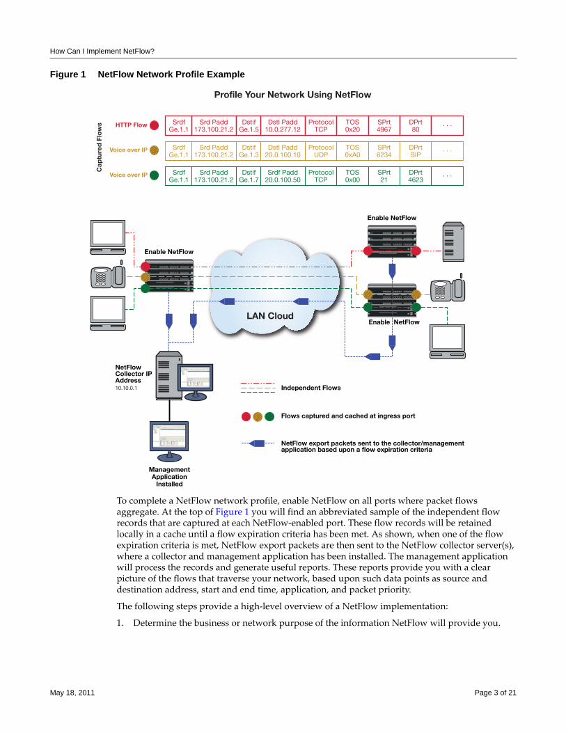
How Can I Implement NetFlow?
Figure 1 NetFlow Network Profile Example
To complete a NetFlow network profile, enable NetFlow on all ports where packet flows aggregate. At the top of Figure 1 you will find an abbreviated sample of the independent flow records that are captured at each NetFlow‐enabled port. These flow records will be retained locally in a cache until a flow expiration criteria has been met. As shown, when one of the flow expiration criteria is met, NetFlow export packets are then sent to the NetFlow collector server(s), where a collector and management application has been installed. The management application will process the records and generate useful reports. These reports provide you with a clear picture of the flows that traverse your network, based upon such data points as source and destination address, start and end time, application, and packet priority.
The following steps provide a high‐level overview of a NetFlow implementation:
1. Determine the business or network purpose of the information NetFlow will provide you.
LAN Cloud
SrdfGe.1.1
Srd Padd173.100.21.2
ProtocolTCP
DstifGe.1.5
TOS0x20
SPrt4967
DPrt80
. . .
SrdfGe.1.1
Srd Padd173.100.21.2
ProtocolUDP
DstifGe.1.3
TOS0xA0
SPrt6234
DPrtSIP
. . .
Profile Your Network Using NetFlowC
aptu
red
Flo
ws HTTP Flow
Voice over IP
Dstl Padd10.0.277.12
Dstl Padd20.0.100.10
SrdfGe.1.1
Srd Padd173.100.21.2
ProtocolTCP
DstifGe.1.7
TOS0x00
SPrt21
DPrt4623
. . .Voice over IP Srdf Padd20.0.100.50
Enable NetFlow
NetFlowCollector IPAddress10.10.0.1
Enable NetFlow
Enable NetFlow
ManagementApplication
Installed
Independent Flows
Flows captured and cached at ingress port
NetFlow export packets sent to the collector/managementapplication based upon a flow expiration criteria
May 18, 2011 Page 3 of 21
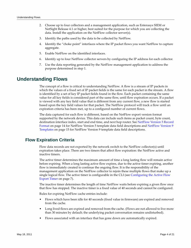
Understanding Flows
2. Choose up to four collectors and a management application, such as Enterasys SIEM or NetSight Release 4.1 or higher, best suited for the purpose for which you are collecting the data. Install the application on the NetFlow collector server(s).
3. Identify the paths used by the data to be collected by NetFlow.
4. Identify the “choke point” interfaces where the IP packet flows you want NetFlow to capture aggregate.
5. Enable NetFlow on the identified interfaces.
6. Identify up to four NetFlow collector servers by configuring the IP address for each collector.
7. Use the data reporting generated by the NetFlow management application to address the purpose determined in step 1.
Understanding FlowsThe concept of a flow is critical to understanding NetFlow. A flow is a stream of IP packets in which the values of a fixed set of IP packet fields is the same for each packet in the stream. A flow is identified by a set of key IP packet fields found in the flow. Each packet containing the same value for all key fields is considered part of the same flow, until flow expiration occurs. If a packet is viewed with any key field value that is different from any current flow, a new flow is started based upon the key field values for that packet. The NetFlow protocol will track a flow until an expiration criteria has been met, up to a configured number of current flows.
The data captured for each flow is different, based on the NetFlow export version format supported by the network device. This data can include such items as packet count, byte count, destination interface index, start and end time, and next hop router. See NetFlow Version 5 Record Format on page 14 for NetFlow Version 5 template data field descriptions and NetFlow Version 9 Templates on page 15 for NetFlow Version 9 template data field descriptions.
Flow Expiration CriteriaFlow data records are not exported by the network switch to the NetFlow collector(s) until expiration takes place. There are two timers that affect flow expiration: the NetFlow active and inactive timers.
The active timer determines the maximum amount of time a long lasting flow will remain active before expiring. When a long lasting active flow expires, due to the active timer expiring, another flow is immediately created to continue the ongoing flow. It is the responsibility of the management application on the NetFlow collector to rejoin these multiple flows that make up a single logical flow. The active timer is configurable in the CLI (see Configuring the Active Flow Export Timer on page 7).
The inactive timer determines the length of time NetFlow waits before expiring a given flow once that flow has stopped. The inactive timer is a fixed value of 40 seconds and cannot be configured.
Rules for expiring NetFlow cache entries include:
• Flows which have been idle for 40 seconds (fixed value in firmware) are expired and removed from the cache.
• Long lived flows are expired and removed from the cache. (Flows are not allowed to live more than 30 minutes by default; the underlying packet conversation remains undisturbed).
• Flows associated with an interface that has gone down are automatically expired.
May 18, 2011 Page 4 of 21
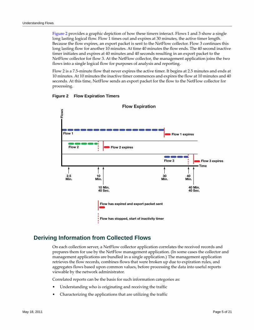
Understanding Flows
Figure 2 provides a graphic depiction of how these timers interact. Flows 1 and 3 show a single long lasting logical flow. Flow 1 times out and expires at 30 minutes, the active timer length. Because the flow expires, an export packet is sent to the NetFlow collector. Flow 3 continues this long lasting flow for another 10 minutes. At time 40 minutes the flow ends. The 40 second inactive timer initiates and expires at 40 minutes and 40 seconds resulting in an export packet to the NetFlow collector for flow 3. At the NetFlow collector, the management application joins the two flows into a single logical flow for purposes of analysis and reporting.
Flow 2 is a 7.5‐minute flow that never expires the active timer. It begins at 2.5 minutes and ends at 10 minutes. At 10 minutes the inactive timer commences and expires the flow at 10 minutes and 40 seconds. At this time, NetFlow sends an export packet for the flow to the NetFlow collector for processing.
Figure 2 Flow Expiration Timers
Deriving Information from Collected FlowsOn each collection server, a NetFlow collector application correlates the received records and prepares them for use by the NetFlow management application. (In some cases the collector and management applications are bundled in a single application.) The management application retrieves the flow records, combines flows that were broken up due to expiration rules, and aggregates flows based upon common values, before processing the data into useful reports viewable by the network administrator.
Correlated reports can be the basis for such information categories as:
• Understanding who is originating and receiving the traffic
• Characterizing the applications that are utilizing the traffic
Flow Expiration
Flo
ws
Time
Flow 1
Flow 2 Flow 2 expires
Flow has expired and export packet sent
Flow has stopped, start of inactivity timer
2.5Min.
10Min.
30Min.
40Min.
10 Min.40 Sec.
40 Min.40 Sec.
Flow 1 expires
Flow 3 Flow 3 expires
May 18, 2011 Page 5 of 21
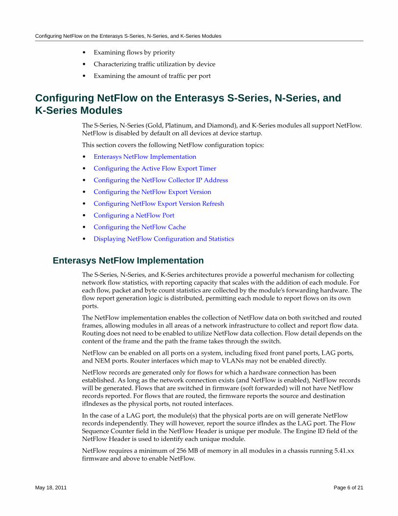
Configuring NetFlow on the Enterasys S-Series, N-Series, and K-Series Modules
• Examining flows by priority
• Characterizing traffic utilization by device
• Examining the amount of traffic per port
Configuring NetFlow on the Enterasys S-Series, N-Series, and K-Series Modules
The S‐Series, N‐Series (Gold, Platinum, and Diamond), and K‐Series modules all support NetFlow. NetFlow is disabled by default on all devices at device startup.
This section covers the following NetFlow configuration topics:
• Enterasys NetFlow Implementation
• Configuring the Active Flow Export Timer
• Configuring the NetFlow Collector IP Address
• Configuring the NetFlow Export Version
• Configuring NetFlow Export Version Refresh
• Configuring a NetFlow Port
• Configuring the NetFlow Cache
• Displaying NetFlow Configuration and Statistics
Enterasys NetFlow ImplementationThe S‐Series, N‐Series, and K‐Series architectures provide a powerful mechanism for collecting network flow statistics, with reporting capacity that scales with the addition of each module. For each flow, packet and byte count statistics are collected by the module’s forwarding hardware. The flow report generation logic is distributed, permitting each module to report flows on its own ports.
The NetFlow implementation enables the collection of NetFlow data on both switched and routed frames, allowing modules in all areas of a network infrastructure to collect and report flow data. Routing does not need to be enabled to utilize NetFlow data collection. Flow detail depends on the content of the frame and the path the frame takes through the switch.
NetFlow can be enabled on all ports on a system, including fixed front panel ports, LAG ports, and NEM ports. Router interfaces which map to VLANs may not be enabled directly.
NetFlow records are generated only for flows for which a hardware connection has been established. As long as the network connection exists (and NetFlow is enabled), NetFlow records will be generated. Flows that are switched in firmware (soft forwarded) will not have NetFlow records reported. For flows that are routed, the firmware reports the source and destination ifIndexes as the physical ports, not routed interfaces.
In the case of a LAG port, the module(s) that the physical ports are on will generate NetFlow records independently. They will however, report the source ifIndex as the LAG port. The Flow Sequence Counter field in the NetFlow Header is unique per module. The Engine ID field of the NetFlow Header is used to identify each unique module.
NetFlow requires a minimum of 256 MB of memory in all modules in a chassis running 5.41.xx firmware and above to enable NetFlow.
May 18, 2011 Page 6 of 21
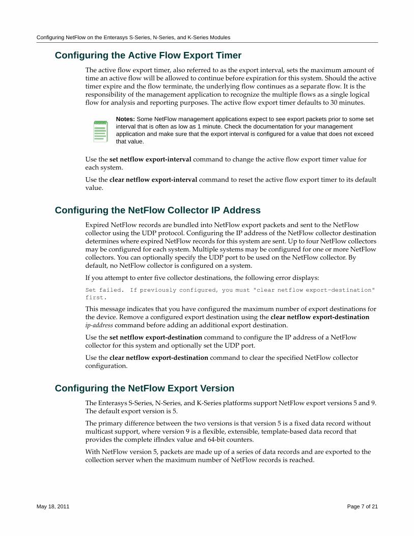
Configuring NetFlow on the Enterasys S-Series, N-Series, and K-Series Modules
Configuring the Active Flow Export TimerThe active flow export timer, also referred to as the export interval, sets the maximum amount of time an active flow will be allowed to continue before expiration for this system. Should the active timer expire and the flow terminate, the underlying flow continues as a separate flow. It is the responsibility of the management application to recognize the multiple flows as a single logical flow for analysis and reporting purposes. The active flow export timer defaults to 30 minutes.
Use the set netflow export‐interval command to change the active flow export timer value for each system.
Use the clear netflow export‐interval command to reset the active flow export timer to its default value.
Configuring the NetFlow Collector IP AddressExpired NetFlow records are bundled into NetFlow export packets and sent to the NetFlow collector using the UDP protocol. Configuring the IP address of the NetFlow collector destination determines where expired NetFlow records for this system are sent. Up to four NetFlow collectors may be configured for each system. Multiple systems may be configured for one or more NetFlow collectors. You can optionally specify the UDP port to be used on the NetFlow collector. By default, no NetFlow collector is configured on a system.
If you attempt to enter five collector destinations, the following error displays:
Set failed. If previously configured, you must "clear netflow export-destination" first.
This message indicates that you have configured the maximum number of export destinations for the device. Remove a configured export destination using the clear netflow export‐destination ip‐address command before adding an additional export destination.
Use the set netflow export‐destination command to configure the IP address of a NetFlow collector for this system and optionally set the UDP port.
Use the clear netflow export‐destination command to clear the specified NetFlow collector configuration.
Configuring the NetFlow Export VersionThe Enterasys S‐Series, N‐Series, and K‐Series platforms support NetFlow export versions 5 and 9. The default export version is 5.
The primary difference between the two versions is that version 5 is a fixed data record without multicast support, where version 9 is a flexible, extensible, template‐based data record that provides the complete ifIndex value and 64‐bit counters.
With NetFlow version 5, packets are made up of a series of data records and are exported to the collection server when the maximum number of NetFlow records is reached.
Notes: Some NetFlow management applications expect to see export packets prior to some set interval that is often as low as 1 minute. Check the documentation for your management application and make sure that the export interval is configured for a value that does not exceed that value.
May 18, 2011 Page 7 of 21
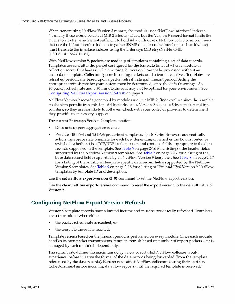
Configuring NetFlow on the Enterasys S-Series, N-Series, and K-Series Modules
When transmitting NetFlow Version 5 reports, the module uses “NetFlow interface” indexes. Normally these would be actual MIB‐2 ifIndex values, but the Version 5 record format limits the values to 2 bytes, which is not sufficient to hold 4‐byte ifIndexes. NetFlow collector applications that use the in/out interface indexes to gather SNMP data about the interface (such as ifName) must translate the interface indexes using the Enterasys MIB etsysNetFlowMIB (1.3.1.6.1.4.1.5624.1.2.61).
With NetFlow version 9, packets are made up of templates containing a set of data records. Templates are sent after the period configured for the template timeout when a module or collection server first boots up. Data records for version 9 cannot be processed without an up‐to‐date template. Collectors ignore incoming packets until a template arrives. Templates are refreshed periodically based upon a packet refresh rate and timeout period. Setting the appropriate refresh rate for your system must be determined, since the default settings of a 20‐packet refresh rate and a 30‐minute timeout may not be optimal for your environment. See Configuring NetFlow Export Version Refresh on page 8.
NetFlow Version 9 records generated by modules use true MIB‐2 ifIndex values since the template mechanism permits transmission of 4‐byte ifIndexes. Version 9 also uses 8‐byte packet and byte counters, so they are less likely to roll over. Check with your collector provider to determine if they provide the necessary support.
The current Enterasys Version 9 implementation:
• Does not support aggregation caches.
• Provides 15 IPv4 and 15 IPv6 predefined templates. The S‐Series firmware automatically selects the appropriate template for each flow depending on whether the flow is routed or switched, whether it is a TCP/UDP packet or not, and contains fields appropriate to the data records supported in the template. See Table 6 on page 2‐16 for a listing of the header fields supported by the NetFlow Version 9 templates. See Table 7 on page 2‐17 for a listing of the base data record fields supported by all NetFlow Version 9 templates. See Table 8 on page 2‐17 for a listing of the additional template specific data record fields supported by the NetFlow Version 9 templates. See Table 9 on page 2‐18 for a listing of IPv4 and IPv6 Version 9 NetFlow templates by template ID and description.
Use the set netflow export‐version {5|9} command to set the NetFlow export version.
Use the clear netflow export‐version command to reset the export version to the default value of Version 5.
Configuring NetFlow Export Version RefreshVersion 9 template records have a limited lifetime and must be periodically refreshed. Templates are retransmitted when either
• the packet refresh rate is reached, or
• the template timeout is reached.
Template refresh based on the timeout period is performed on every module. Since each module handles its own packet transmissions, template refresh based on number of export packets sent is managed by each module independently.
The refresh rate defines the maximum delay a new or restarted NetFlow collector would experience, before it learns the format of the data records being forwarded (from the template referenced by the data records). Refresh rates affect NetFlow collectors during their start up. Collectors must ignore incoming data flow reports until the required template is received.
May 18, 2011 Page 8 of 21
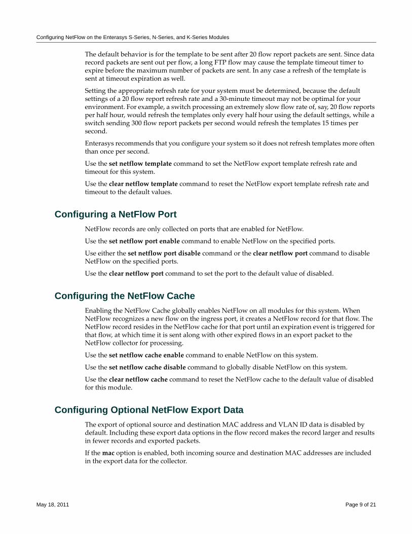
Configuring NetFlow on the Enterasys S-Series, N-Series, and K-Series Modules
The default behavior is for the template to be sent after 20 flow report packets are sent. Since data record packets are sent out per flow, a long FTP flow may cause the template timeout timer to expire before the maximum number of packets are sent. In any case a refresh of the template is sent at timeout expiration as well.
Setting the appropriate refresh rate for your system must be determined, because the default settings of a 20 flow report refresh rate and a 30‐minute timeout may not be optimal for your environment. For example, a switch processing an extremely slow flow rate of, say, 20 flow reports per half hour, would refresh the templates only every half hour using the default settings, while a switch sending 300 flow report packets per second would refresh the templates 15 times per second.
Enterasys recommends that you configure your system so it does not refresh templates more often than once per second.
Use the set netflow template command to set the NetFlow export template refresh rate and timeout for this system.
Use the clear netflow template command to reset the NetFlow export template refresh rate and timeout to the default values.
Configuring a NetFlow PortNetFlow records are only collected on ports that are enabled for NetFlow.
Use the set netflow port enable command to enable NetFlow on the specified ports.
Use either the set netflow port disable command or the clear netflow port command to disable NetFlow on the specified ports.
Use the clear netflow port command to set the port to the default value of disabled.
Configuring the NetFlow CacheEnabling the NetFlow Cache globally enables NetFlow on all modules for this system. When NetFlow recognizes a new flow on the ingress port, it creates a NetFlow record for that flow. The NetFlow record resides in the NetFlow cache for that port until an expiration event is triggered for that flow, at which time it is sent along with other expired flows in an export packet to the NetFlow collector for processing.
Use the set netflow cache enable command to enable NetFlow on this system.
Use the set netflow cache disable command to globally disable NetFlow on this system.
Use the clear netflow cache command to reset the NetFlow cache to the default value of disabled for this module.
Configuring Optional NetFlow Export DataThe export of optional source and destination MAC address and VLAN ID data is disabled by default. Including these export data options in the flow record makes the record larger and results in fewer records and exported packets.
If the mac option is enabled, both incoming source and destination MAC addresses are included in the export data for the collector.
May 18, 2011 Page 9 of 21
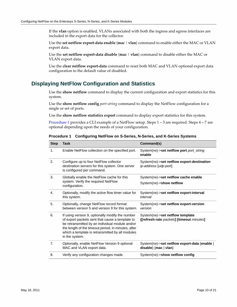
Configuring NetFlow on the Enterasys S-Series, N-Series, and K-Series Modules
If the vlan option is enabled, VLANs associated with both the ingress and egress interfaces are included in the export data for the collector.
Use the set netflow export‐data enable {mac | vlan} command to enable either the MAC or VLAN export data.
Use the set netflow export‐data disable {mac | vlan} command to disable either the MAC or VLAN export data.
Use the clear netflow export‐data command to reset both MAC and VLAN optional export data configuration to the default value of disabled.
Displaying NetFlow Configuration and StatisticsUse the show netflow command to display the current configuration and export statistics for this system.
Use the show netflow config port‐string command to display the NetFlow configuration for a single or set of ports.
Use the show netflow statistics export command to display export statistics for this system.
Procedure 1 provides a CLI example of a NetFlow setup. Steps 1 – 3 are required. Steps 4 – 7 are optional depending upon the needs of your configuration.
Procedure 1 Configuring NetFlow on S-Series, N-Series, and K-Series Systems
Step Task Command(s)
1. Enable NetFlow collection on the specified port. System(rw)->set netflow port port_string enable
2. Configure up to four NetFlow collector destination servers for this system. One server is configured per command.
System(rw)->set netflow export-destination ip-address [udp-port]
3. Globally enable the NetFlow cache for this system. Verify the required NetFlow configuration.
System(rw)->set netflow cache enableSystem(rw)->show netflow
4. Optionally, modify the active flow timer value for this system.
System(rw)->set netflow export-interval interval
5. Optionally, change NetFlow record format between version 5 and version 9 for this system.
System(rw)->set netflow export-version version
6. If using version 9, optionally modify the number of export packets sent that cause a template to be retransmitted by an individual module and/or the length of the timeout period, in minutes, after which a template is retransmitted by all modules in the system.
System(rw)->set netflow template {[refresh-rate packets] [timeout minutes]
7. Optionally, enable NetFlow Version 9 optional MAC and VLAN export data.
System(rw)->set netflow export-data {enable | disable} {mac | vlan}
8. Verify any configuration changes made. System(rw)->show netflow config
May 18, 2011 Page 10 of 21
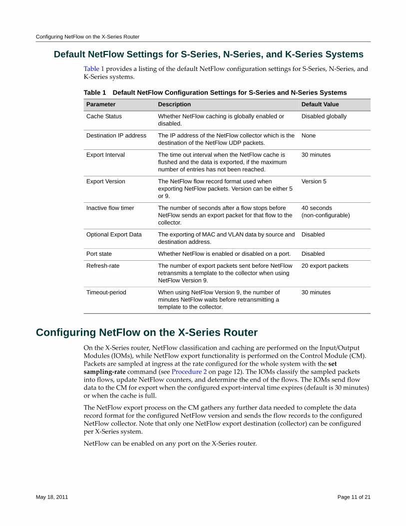
Configuring NetFlow on the X-Series Router
Default NetFlow Settings for S-Series, N-Series, and K-Series SystemsTable 1 provides a listing of the default NetFlow configuration settings for S‐Series, N‐Series, and K‐Series systems.
Configuring NetFlow on the X-Series RouterOn the X‐Series router, NetFlow classification and caching are performed on the Input/Output Modules (IOMs), while NetFlow export functionality is performed on the Control Module (CM). Packets are sampled at ingress at the rate configured for the whole system with the set sampling‐rate command (see Procedure 2 on page 12). The IOMs classify the sampled packets into flows, update NetFlow counters, and determine the end of the flows. The IOMs send flow data to the CM for export when the configured export‐interval time expires (default is 30 minutes) or when the cache is full.
The NetFlow export process on the CM gathers any further data needed to complete the data record format for the configured NetFlow version and sends the flow records to the configured NetFlow collector. Note that only one NetFlow export destination (collector) can be configured per X‐Series system.
NetFlow can be enabled on any port on the X‐Series router.
Table 1 Default NetFlow Configuration Settings for S-Series and N-Series SystemsParameter Description Default Value
Cache Status Whether NetFlow caching is globally enabled or disabled.
Disabled globally
Destination IP address The IP address of the NetFlow collector which is the destination of the NetFlow UDP packets.
None
Export Interval The time out interval when the NetFlow cache is flushed and the data is exported, if the maximum number of entries has not been reached.
30 minutes
Export Version The NetFlow flow record format used when exporting NetFlow packets. Version can be either 5 or 9.
Version 5
Inactive flow timer The number of seconds after a flow stops before NetFlow sends an export packet for that flow to the collector.
40 seconds (non-configurable)
Optional Export Data The exporting of MAC and VLAN data by source and destination address.
Disabled
Port state Whether NetFlow is enabled or disabled on a port. Disabled
Refresh-rate The number of export packets sent before NetFlow retransmits a template to the collector when using NetFlow Version 9.
20 export packets
Timeout-period When using NetFlow Version 9, the number of minutes NetFlow waits before retransmitting a template to the collector.
30 minutes
May 18, 2011 Page 11 of 21
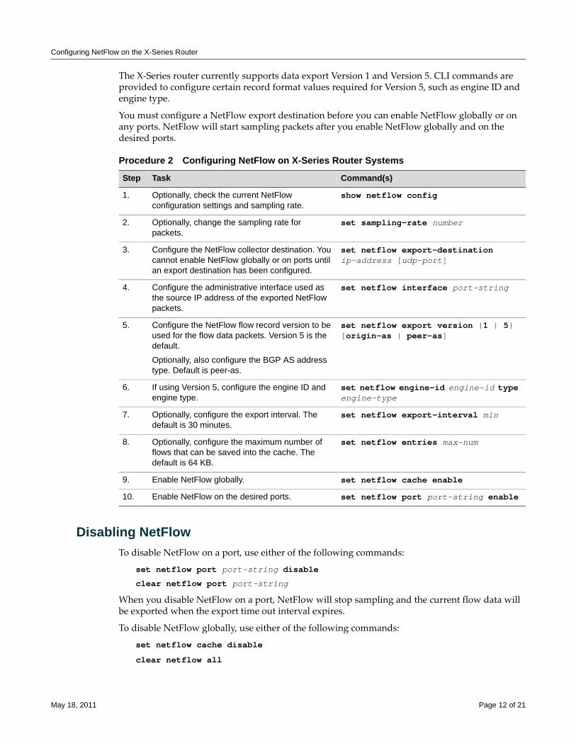
Configuring NetFlow on the X-Series Router
The X‐Series router currently supports data export Version 1 and Version 5. CLI commands are provided to configure certain record format values required for Version 5, such as engine ID and engine type.
You must configure a NetFlow export destination before you can enable NetFlow globally or on any ports. NetFlow will start sampling packets after you enable NetFlow globally and on the desired ports.
Disabling NetFlowTo disable NetFlow on a port, use either of the following commands:
set netflow port port-string disable
clear netflow port port-string
When you disable NetFlow on a port, NetFlow will stop sampling and the current flow data will be exported when the export time out interval expires.
To disable NetFlow globally, use either of the following commands:
set netflow cache disable
clear netflow all
Procedure 2 Configuring NetFlow on X-Series Router Systems
Step Task Command(s)
1. Optionally, check the current NetFlow configuration settings and sampling rate.
show netflow config
2. Optionally, change the sampling rate for packets.
set sampling-rate number
3. Configure the NetFlow collector destination. You cannot enable NetFlow globally or on ports until an export destination has been configured.
set netflow export-destination ip-address [udp-port]
4. Configure the administrative interface used as the source IP address of the exported NetFlow packets.
set netflow interface port-string
5. Configure the NetFlow flow record version to be used for the flow data packets. Version 5 is the default.
Optionally, also configure the BGP AS address type. Default is peer-as.
set netflow export version {1 | 5} [origin-as | peer-as]
6. If using Version 5, configure the engine ID and engine type.
set netflow engine-id engine-id type engine-type
7. Optionally, configure the export interval. The default is 30 minutes.
set netflow export-interval min
8. Optionally, configure the maximum number of flows that can be saved into the cache. The default is 64 KB.
set netflow entries max-num
9. Enable NetFlow globally. set netflow cache enable
10. Enable NetFlow on the desired ports. set netflow port port-string enable
May 18, 2011 Page 12 of 21
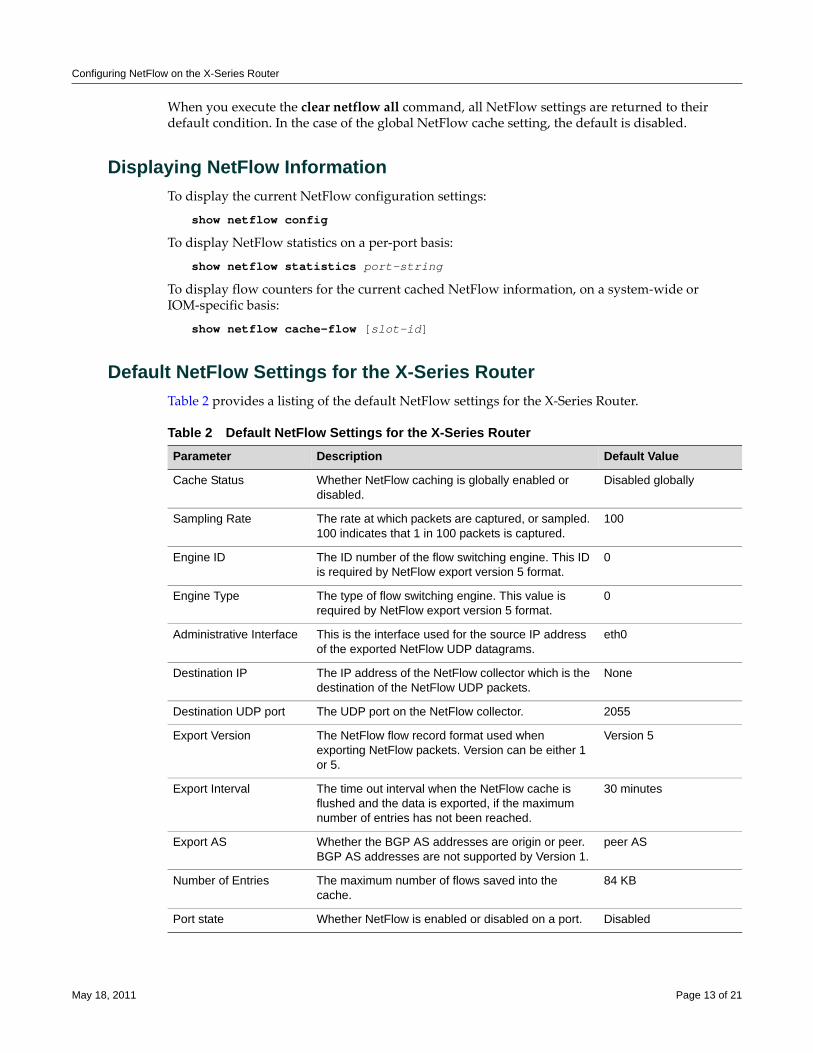
Configuring NetFlow on the X-Series Router
When you execute the clear netflow all command, all NetFlow settings are returned to their default condition. In the case of the global NetFlow cache setting, the default is disabled.
Displaying NetFlow InformationTo display the current NetFlow configuration settings:
show netflow config
To display NetFlow statistics on a per‐port basis:
show netflow statistics port-string
To display flow counters for the current cached NetFlow information, on a system‐wide or IOM‐specific basis:
show netflow cache-flow [slot-id]
Default NetFlow Settings for the X-Series RouterTable 2 provides a listing of the default NetFlow settings for the X‐Series Router.
Table 2 Default NetFlow Settings for the X-Series RouterParameter Description Default Value
Cache Status Whether NetFlow caching is globally enabled or disabled.
Disabled globally
Sampling Rate The rate at which packets are captured, or sampled. 100 indicates that 1 in 100 packets is captured.
100
Engine ID The ID number of the flow switching engine. This ID is required by NetFlow export version 5 format.
0
Engine Type The type of flow switching engine. This value is required by NetFlow export version 5 format.
0
Administrative Interface This is the interface used for the source IP address of the exported NetFlow UDP datagrams.
eth0
Destination IP The IP address of the NetFlow collector which is the destination of the NetFlow UDP packets.
None
Destination UDP port The UDP port on the NetFlow collector. 2055
Export Version The NetFlow flow record format used when exporting NetFlow packets. Version can be either 1 or 5.
Version 5
Export Interval The time out interval when the NetFlow cache is flushed and the data is exported, if the maximum number of entries has not been reached.
30 minutes
Export AS Whether the BGP AS addresses are origin or peer. BGP AS addresses are not supported by Version 1.
peer AS
Number of Entries The maximum number of flows saved into the cache.
84 KB
Port state Whether NetFlow is enabled or disabled on a port. Disabled
May 18, 2011 Page 13 of 21
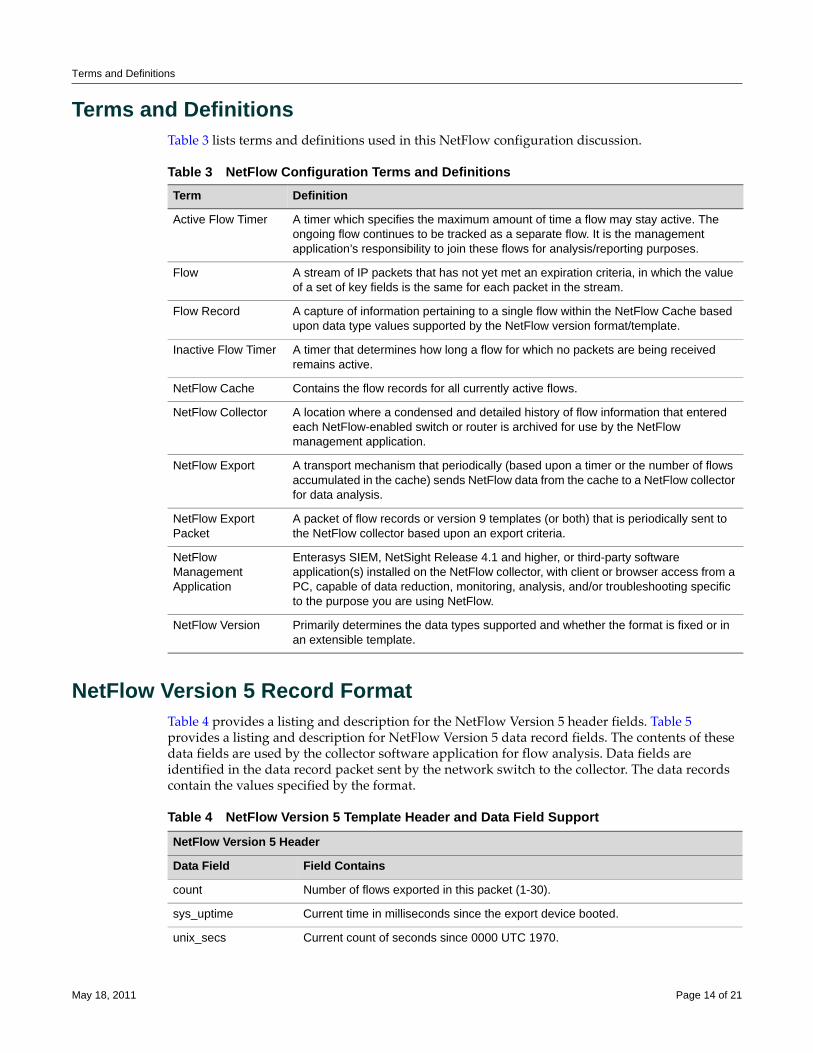
Terms and Definitions
Terms and DefinitionsTable 3 lists terms and definitions used in this NetFlow configuration discussion.
NetFlow Version 5 Record FormatTable 4 provides a listing and description for the NetFlow Version 5 header fields. Table 5 provides a listing and description for NetFlow Version 5 data record fields. The contents of these data fields are used by the collector software application for flow analysis. Data fields are identified in the data record packet sent by the network switch to the collector. The data records contain the values specified by the format.
Table 3 NetFlow Configuration Terms and Definitions Term Definition
Active Flow Timer A timer which specifies the maximum amount of time a flow may stay active. The ongoing flow continues to be tracked as a separate flow. It is the management application’s responsibility to join these flows for analysis/reporting purposes.
Flow A stream of IP packets that has not yet met an expiration criteria, in which the value of a set of key fields is the same for each packet in the stream.
Flow Record A capture of information pertaining to a single flow within the NetFlow Cache based upon data type values supported by the NetFlow version format/template.
Inactive Flow Timer A timer that determines how long a flow for which no packets are being received remains active.
NetFlow Cache Contains the flow records for all currently active flows.
NetFlow Collector A location where a condensed and detailed history of flow information that entered each NetFlow-enabled switch or router is archived for use by the NetFlow management application.
NetFlow Export A transport mechanism that periodically (based upon a timer or the number of flows accumulated in the cache) sends NetFlow data from the cache to a NetFlow collector for data analysis.
NetFlow Export Packet
A packet of flow records or version 9 templates (or both) that is periodically sent to the NetFlow collector based upon an export criteria.
NetFlow Management Application
Enterasys SIEM, NetSight Release 4.1 and higher, or third-party software application(s) installed on the NetFlow collector, with client or browser access from a PC, capable of data reduction, monitoring, analysis, and/or troubleshooting specific to the purpose you are using NetFlow.
NetFlow Version Primarily determines the data types supported and whether the format is fixed or in an extensible template.
Table 4 NetFlow Version 5 Template Header and Data Field Support
NetFlow Version 5 Header
Data Field Field Contains
count Number of flows exported in this packet (1-30).
sys_uptime Current time in milliseconds since the export device booted.
unix_secs Current count of seconds since 0000 UTC 1970.
May 18, 2011 Page 14 of 21
NetFlow Version 9 Templates
NetFlow Version 9 TemplatesThe NetFlow Version 9 implementation supports 15 IPv4 (templates 256 through 271) and 15 IPv6 (templates 272 through 287) Version 9 templates. The templates are Enterasys defined supporting
unix_nsecs Residual nanoseconds since 0000 UTC 1970.
flow_sequence Sequence counter of total flows seen.
engine_type Type of flow-switching engine.
engine_id Slot number of the flow-switching engine.
sampling_interval First two bits hold the sampling mode; remaining 14 bits hold value of sampling interval.
count Number of flows exported in this packet (1-30).
Table 5 NetFlow Version 5 Data Record Field FormatNetFlow Version 5 Data Record Format
Data Field Field Contains
srcaddr Source IP address of the device that transmitted the packet.
dstaddr IP address of the destination of the packet.
nexthop IP address of the next hop router.
input SNMP index of input interface.
output SNMP index of output interface.
dPkts Number of packets in the flow.
dOctets Total number of Layer 3 bytes in the packets of the flow.
first SysUptime at start of flow.
last SysUptime at the time the last packet of the flow was received.
srcport TCP/UDP source port number or equivalent.
dstport TCP/UDP destination port number or equivalent.
pad1 Unused (zero) bytes.
tcp_flags Cumulative OR of TCP flags.
prot IP protocol type (for example, TCP = 6; UDP = 17).
tos IP type of service (ToS).
src_as Autonomous system number of the source, either origin or peer.
dst_as Autonomous system number of the destination, either origin or peer.
src_mask Source address prefix mask bits.
dst_mask Destination address prefix mask bits.
pad2 Unused (zero) bytes.
Table 4 NetFlow Version 5 Template Header and Data Field Support (continued)
May 18, 2011 Page 15 of 21
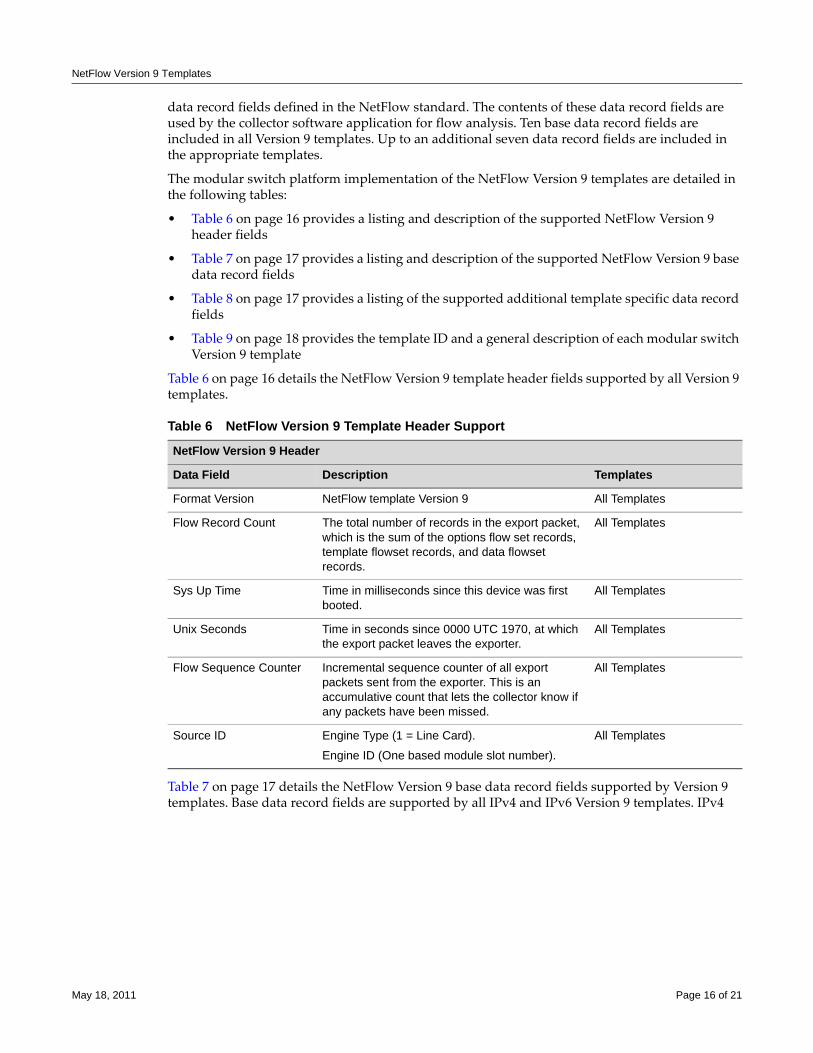
NetFlow Version 9 Templates
data record fields defined in the NetFlow standard. The contents of these data record fields are used by the collector software application for flow analysis. Ten base data record fields are included in all Version 9 templates. Up to an additional seven data record fields are included in the appropriate templates.
The modular switch platform implementation of the NetFlow Version 9 templates are detailed in the following tables:
• Table 6 on page 16 provides a listing and description of the supported NetFlow Version 9 header fields
• Table 7 on page 17 provides a listing and description of the supported NetFlow Version 9 base data record fields
• Table 8 on page 17 provides a listing of the supported additional template specific data record fields
• Table 9 on page 18 provides the template ID and a general description of each modular switch Version 9 template
Table 6 on page 16 details the NetFlow Version 9 template header fields supported by all Version 9 templates.
Table 7 on page 17 details the NetFlow Version 9 base data record fields supported by Version 9 templates. Base data record fields are supported by all IPv4 and IPv6 Version 9 templates. IPv4
Table 6 NetFlow Version 9 Template Header Support
NetFlow Version 9 Header
Data Field Description Templates
Format Version NetFlow template Version 9 All Templates
Flow Record Count The total number of records in the export packet, which is the sum of the options flow set records, template flowset records, and data flowset records.
All Templates
Sys Up Time Time in milliseconds since this device was first booted.
All Templates
Unix Seconds Time in seconds since 0000 UTC 1970, at which the export packet leaves the exporter.
All Templates
Flow Sequence Counter Incremental sequence counter of all export packets sent from the exporter. This is an accumulative count that lets the collector know if any packets have been missed.
All Templates
Source ID Engine Type (1 = Line Card).
Engine ID (One based module slot number).
All Templates
May 18, 2011 Page 16 of 21
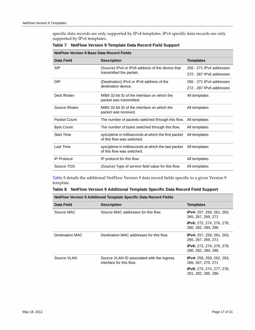
NetFlow Version 9 Templates
specific data records are only supported by IPv4 templates. IPv6 specific data records are only supported by IPv6 templates.
Table 8 details the additional NetFlow Version 9 data record fields specific to a given Version 9 template.
Table 7 NetFlow Version 9 Template Data Record Field Support
NetFlow Version 9 Base Data Record Fields
Data Field Description Templates
SIP (Source) IPv4 or IPv6 address of the device that transmitted the packet.
256 - 271 IPv4 addresses
272 - 287 IPv6 addresses
DIP (Destination) IPv4 or IPv6 address of the destination device.
256 - 271 IPv4 addresses
272 - 287 IPv6 addresses
Dest IfIndex MIBII 32-bit ID of the interface on which the packet was transmitted.
All templates
Source IfIndex MIBII 32-bit ID of the interface on which the packet was received.
All templates
Packet Count The number of packets switched through this flow. All templates
Byte Count The number of bytes switched through this flow. All templates
Start Time sysUptime in milliseconds at which the first packet of this flow was switched.
All templates
Last Time sysUptime in milliseconds at which the last packet of this flow was switched.
All templates
IP Protocol IP protocol for this flow. All templates
Source TOS (Source) Type of service field value for this flow. All templates
Table 8 NetFlow Version 9 Additional Template Specific Data Record Field Support
NetFlow Version 9 Additional Template Specific Data Record Fields
Data Field Description Templates
Source MAC Source MAC addresses for this flow. IPv4: 257, 259, 261, 263, 265, 267, 269, 271
IPv6: 272, 274, 276, 278, 280, 282, 284, 286
Destination MAC Destination MAC addresses for this flow. IPv4: 257, 259, 261, 263, 265, 267, 269, 271
IPv6: 272, 274, 276, 278, 280, 282, 284, 286
Source VLAN Source VLAN ID associated with the ingress interface for this flow.
IPv4: 258, 259, 262, 263, 266, 267, 270, 271
IPv6: 273, 274, 277, 278, 281, 282, 285, 286
May 18, 2011 Page 17 of 21
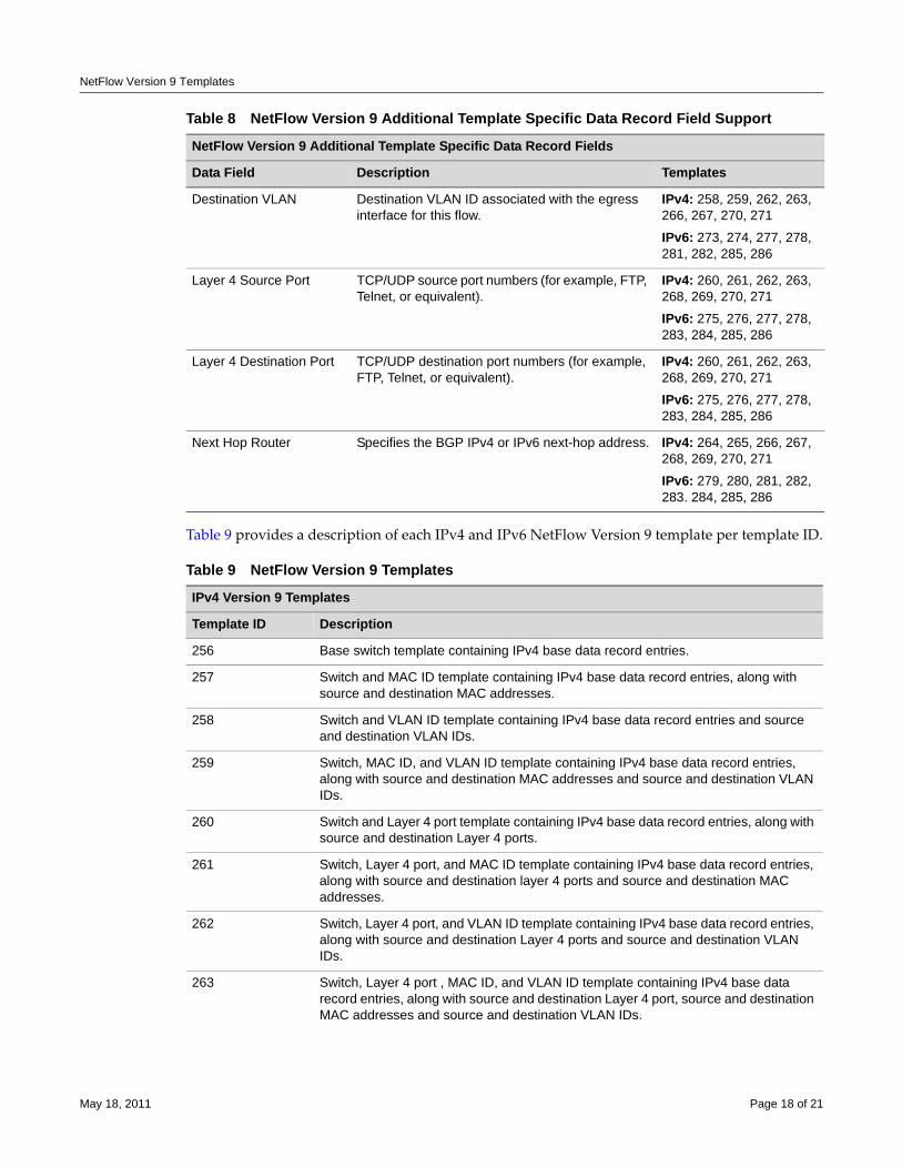
NetFlow Version 9 Templates
Table 9 provides a description of each IPv4 and IPv6 NetFlow Version 9 template per template ID.
Destination VLAN Destination VLAN ID associated with the egress interface for this flow.
IPv4: 258, 259, 262, 263, 266, 267, 270, 271
IPv6: 273, 274, 277, 278, 281, 282, 285, 286
Layer 4 Source Port TCP/UDP source port numbers (for example, FTP, Telnet, or equivalent).
IPv4: 260, 261, 262, 263, 268, 269, 270, 271
IPv6: 275, 276, 277, 278, 283, 284, 285, 286
Layer 4 Destination Port TCP/UDP destination port numbers (for example, FTP, Telnet, or equivalent).
IPv4: 260, 261, 262, 263, 268, 269, 270, 271
IPv6: 275, 276, 277, 278, 283, 284, 285, 286
Next Hop Router Specifies the BGP IPv4 or IPv6 next-hop address. IPv4: 264, 265, 266, 267, 268, 269, 270, 271
IPv6: 279, 280, 281, 282, 283. 284, 285, 286
Table 9 NetFlow Version 9 Templates
IPv4 Version 9 Templates
Template ID Description
256 Base switch template containing IPv4 base data record entries.
257 Switch and MAC ID template containing IPv4 base data record entries, along with source and destination MAC addresses.
258 Switch and VLAN ID template containing IPv4 base data record entries and source and destination VLAN IDs.
259 Switch, MAC ID, and VLAN ID template containing IPv4 base data record entries, along with source and destination MAC addresses and source and destination VLAN IDs.
260 Switch and Layer 4 port template containing IPv4 base data record entries, along with source and destination Layer 4 ports.
261 Switch, Layer 4 port, and MAC ID template containing IPv4 base data record entries, along with source and destination layer 4 ports and source and destination MAC addresses.
262 Switch, Layer 4 port, and VLAN ID template containing IPv4 base data record entries, along with source and destination Layer 4 ports and source and destination VLAN IDs.
263 Switch, Layer 4 port , MAC ID, and VLAN ID template containing IPv4 base data record entries, along with source and destination Layer 4 port, source and destination MAC addresses and source and destination VLAN IDs.
Table 8 NetFlow Version 9 Additional Template Specific Data Record Field Support
NetFlow Version 9 Additional Template Specific Data Record Fields
Data Field Description Templates
May 18, 2011 Page 18 of 21
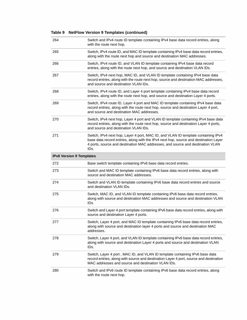
264 Switch and IPv4 route ID template containing IPv4 base data record entries, along with the route next hop.
265 Switch, IPv4 route ID, and MAC ID template containing IPv4 base data record entries, along with the route next hop and source and destination MAC addresses.
266 Switch, IPv4 route ID, and VLAN ID template containing IPv4 base data record entries, along with the route next hop, and source and destination VLAN IDs.
267 Switch, IPv4 next hop, MAC ID, and VLAN ID template containing IPv4 base data record entries, along with the route next hop, source and destination MAC addresses, and source and destination VLAN IDs.
268 Switch, IPv4 route ID, and Layer 4 port template containing IPv4 base data record entries, along with the route next hop, and source and destination Layer 4 ports.
269 Switch, IPv4 route ID, Layer 4 port and MAC ID template containing IPv4 base data record entries, along with the route next hop, source and destination Layer 4 port, and source and destination MAC addresses.
270 Switch, IPv4 next hop, Layer 4 port and VLAN ID template containing IPv4 base data record entries, along with the route next hop, source and destination Layer 4 ports, and source and destination VLAN IDs.
271 Switch, IPv4 next hop, Layer 4 port, MAC ID, and VLAN ID template containing IPv4 base data record entries, along with the IPv4 next hop, source and destination Layer 4 ports, source and destination MAC addresses, and source and destination VLAN IDs.
IPv6 Version 9 Templates
272 Base switch template containing IPv6 base data record entries.
273 Switch and MAC ID template containing IPv6 base data record entries, along with source and destination MAC addresses.
274 Switch and VLAN ID template containing IPv6 base data record entries and source and destination VLAN IDs.
275 Switch, MAC ID, and VLAN ID template containing IPv6 base data record entries, along with source and destination MAC addresses and source and destination VLAN IDs.
276 Switch and Layer 4 port template containing IPv6 base data record entries, along with source and destination Layer 4 ports.
277 Switch, Layer 4 port, and MAC ID template containing IPv6 base data record entries, along with source and destination layer 4 ports and source and destination MAC addresses.
278 Switch, Layer 4 port, and VLAN ID template containing IPv6 base data record entries, along with source and destination Layer 4 ports and source and destination VLAN IDs.
279 Switch, Layer 4 port , MAC ID, and VLAN ID template containing IPv6 base data record entries, along with source and destination Layer 4 port, source and destination MAC addresses and source and destination VLAN IDs.
280 Switch and IPv6 route ID template containing IPv6 base data record entries, along with the route next hop.
Table 9 NetFlow Version 9 Templates (continued)
NetFlow Version 9 Templates
281 Switch, IPv6 route ID, and MAC ID template containing IPv6 base data record entries, along with the route next hop and source and destination MAC addresses.
282 Switch, IPv6 route ID, and VLAN ID template containing IPv6 base data record entries, along with the route next hop, and source and destination VLAN IDs.
283 Switch, IPv6 next hop, MAC ID, and VLAN ID template containing IPv6 base data record entries, along with the route next hop, source and destination MAC addresses, and source and destination VLAN IDs.
284 Switch, IPv6 route ID, and Layer 4 port template containing IPv6 base data record entries, along with the route next hop, and source and destination Layer 4 ports.
285 Switch, IPv6 route ID, Layer 4 port and MAC ID template containing IPv6 base data record entries, along with the route next hop, source and destination Layer 4 port, and source and destination MAC addresses.
286 Switch, IPv6 next hop, Layer 4 port and VLAN ID template containing IPv6 base data record entries, along with the route next hop, source and destination Layer 4 ports, and source and destination VLAN IDs.
287 Switch, IPv6 next hop, Layer 4 port, MAC ID, and VLAN ID template containing IPv6 base data record entries, along with the IPv6 next hop, source and destination Layer 4 ports, source and destination MAC addresses, and source and destination VLAN IDs.
Table 9 NetFlow Version 9 Templates (continued)
May 18, 2011 Page 20 of 21
Enterasys Networks reserves the right to make changes in specifications and other information contained in this document and its web site without prior notice. The reader should in all cases consult Enterasys Networks to determine whether any such changes have been made.
The hardware, firmware, or software described in this document is subject to change without notice.
IN NO EVENT SHALL ENTERASYS NETWORKS BE LIABLE FOR ANY INCIDENTAL, INDIRECT, SPECIAL, OR CONSEQUENTIAL DAMAGES WHATSOEVER (INCLUDING BUT NOT LIMITED TO LOST PROFITS) ARISING OUT OF OR RELATED TO THIS DOCUMENT, WEB SITE, OR THE INFORMATION CONTAINED IN THEM, EVEN IF ENTERASYS NETWORKS HAS BEEN ADVISED OF, KNEW OF, OR SHOULD HAVE KNOWN OF, THE POSSIBILITY OF SUCH DAMAGES.
Enterasys Networks, Inc.50 Minuteman RoadAndover, MA 01810
© 2011 Enterasys Networks, Inc. All rights reserved.
ENTERASYS, ENTERASYS NETWORKS, ENTERASYS S‐SERIES, ENTERASYS NETSIGHT, LANVIEW, WEBVIEW, and any logos associated therewith, are trademarks or registered trademarks of Enterasys Networks, Inc., in the United States and other countries.
All other product names mentioned in this manual may be trademarks or registered trademarks of their respective companies.
Revision History
Date Description
May 18, 2011 First Release.
July 28, 2008 Added Enterasys Registration mark.
October 15, 2008 Corrected Tradmarks list.
January 23, 2009 Cosmetic changes only.
July 15, 2010 Updated for S-Series platform.
May 18, 2011 Updated for Release 7.21 changes and K-Series platform.
Configuring Power over Ethernet Management
This document provides information about configuring and monitoring Power over Ethernet (PoE) on the PoE‐compliant models of the Enterasys® N‐Series, S‐Series, and K‐Series modular switches, A‐Series, B‐Series, C‐Series stackable fixed switches, and D‐Series and G‐Series standalone switches.
What is PoE?PoE, defined in IEEE standards 802.3af and 802.3at, refers to the ability to provide 48 Vdc (for 802.3af) or 54 Vdc (for 802.3at) operational power through an Ethernet cable from a switch or other device that can provide a PoE‐compliant port connection to a powered device (PD). Examples of PDs are the following:
• Voice over IP devices such as PoE‐compliant digital telephones
• Pan/Tilt/Zoom (PTZ) IP surveillance cameras
• Devices that support Wireless Application Protocol (WAP) such as wireless access points
Ethernet implementations employ differential signals over twisted pair cables. This requires a minimum of two twisted pairs for a single physical link. Both ends of the cable are isolated with transformers blocking any DC or common mode voltage on the signal pair. PoE exploits this fact by using two twisted pairs as the two conductors to supply a direct current to a PD. One pair carries the power supply current and the other pair provides a path for the return current.
Why Would I Use PoE in My Network?Using PoE allows you to operate PDs in locations without local power (that is, without AC outlets). Having such a network setup can reduce the costs associated with installing electrical wiring and AC outlets to power the various devices.
Notes: PoE is not supported on Enterasys® I-Series or X-Series devices.
For information about... Refer to page...
What is PoE? 1
Why Would I Use PoE in My Network? 1
How Do I Implement PoE? 2
Configuring PoE 4
June 3, 2011 Page 1 of 14
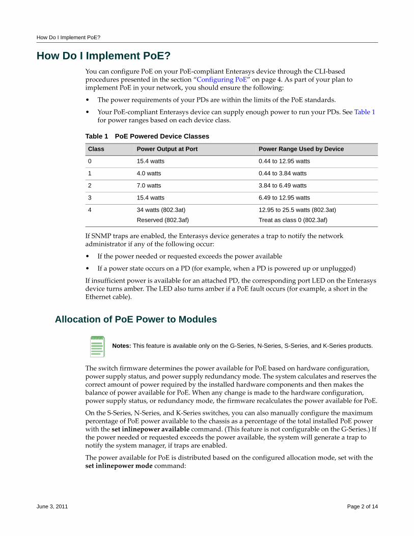
How Do I Implement PoE?
How Do I Implement PoE?You can configure PoE on your PoE‐compliant Enterasys device through the CLI‐based procedures presented in the section “Configuring PoE” on page 4. As part of your plan to implement PoE in your network, you should ensure the following:
• The power requirements of your PDs are within the limits of the PoE standards.
• Your PoE‐compliant Enterasys device can supply enough power to run your PDs. See Table 1 for power ranges based on each device class.
If SNMP traps are enabled, the Enterasys device generates a trap to notify the network administrator if any of the following occur:
• If the power needed or requested exceeds the power available
• If a power state occurs on a PD (for example, when a PD is powered up or unplugged)
If insufficient power is available for an attached PD, the corresponding port LED on the Enterasys device turns amber. The LED also turns amber if a PoE fault occurs (for example, a short in the Ethernet cable).
Allocation of PoE Power to Modules
The switch firmware determines the power available for PoE based on hardware configuration, power supply status, and power supply redundancy mode. The system calculates and reserves the correct amount of power required by the installed hardware components and then makes the balance of power available for PoE. When any change is made to the hardware configuration, power supply status, or redundancy mode, the firmware recalculates the power available for PoE.
On the S‐Series, N‐Series, and K‐Series switches, you can also manually configure the maximum percentage of PoE power available to the chassis as a percentage of the total installed PoE power with the set inlinepower available command. (This feature is not configurable on the G‐Series.) If the power needed or requested exceeds the power available, the system will generate a trap to notify the system manager, if traps are enabled.
The power available for PoE is distributed based on the configured allocation mode, set with the set inlinepower mode command:
Table 1 PoE Powered Device Classes
Class Power Output at Port Power Range Used by Device
0 15.4 watts 0.44 to 12.95 watts
1 4.0 watts 0.44 to 3.84 watts
2 7.0 watts 3.84 to 6.49 watts
3 15.4 watts 6.49 to 12.95 watts
4 34 watts (802.3at)
Reserved (802.3af)
12.95 to 25.5 watts (802.3at)
Treat as class 0 (802.3af)
Notes: This feature is available only on the G-Series, N-Series, S-Series, and K-Series products.
June 3, 2011 Page 2 of 14
How Do I Implement PoE?
• Automatic mode, in which available power is distributed evenly to PoE‐capable modules based on PoE port count. (This is the default mode.) Any change in available power, due to a change in power supply status or redundancy mode or to the addition or removal of modules, will trigger an automatic redistribution of power.
• Manual mode, in which the power budget for each PoE‐capable module is manually configured, using either CLI commands or the MIBs. The sum of the wattage configured for each module cannot exceed the total power available on the switch for PoE.
The power budget for each PoE‐capable module can be configured manually on the G‐Series with the command set inlinepower assign and on the S‐Series, N‐Series, and K‐Series with the command set inlinepower assigned.
The configured wattage assignments are used to calculate each slot’s percentage of total available power. If the total available PoE power is reduced, a redistribution of available power will occur, applying the calculated percentages.
When Manual Mode is ConfiguredWhen manual distribution mode is configured, if a PoE module is added to the switch, the PoE power budget for existing modules will not be recalculated. The new module will have a power budget of zero until it is manually provisioned. Since the sum of the manually provisioned wattages cannot exceed the total system power available, it may be necessary to adjust existing budgets to free up power for the new module.
When a PoE module is removed from a switch configured with manual power distribution mode, the PoE budget for each module will not be recalculated, based on the assumption that the module removed will be replaced with a new module that should receive the same amount of PoE power.
As noted above, if the total available PoE power is reduced, the power will automatically be redistributed based on applying the calculated percentages. If an additional PoE supply is installed, there is no impact on the assigned PoE since specific wattages have been assigned to each module. Only the “Total Power Detected” value will change. The extra PoE power, however, is available for further redistribution manually.
Management of PoE Power to PDs
For each PoE‐capable module or switch (for the products listed above), you can configure how its PoE controller makes power available to attached powered devices (PDs). On a per module basis, you can configure:
• Real‐time mode, in which the PoE controller calculates the power needed by a PD based on the actual power consumption of the attached devices.
• Class mode, in which the PoE controller manages power based on the IEEE 802.3af/.3at definition of the class limits advertised by the attached devices, with the exception that for class 0 and class 4 devices, actual power consumption will always be used. In this mode, the maximum amount of power required by a device in the advertised class is reserved for the port, regardless of the actual amount of power being used by the device.
Power management to PDs is configured with the command set inlinepower management. PoE classes are defined in Table 1 on page 2.
Note: This feature is available only on B5, C5, G-Series, N-Series, S-Series, and K-Series products.
June 3, 2011 Page 3 of 14
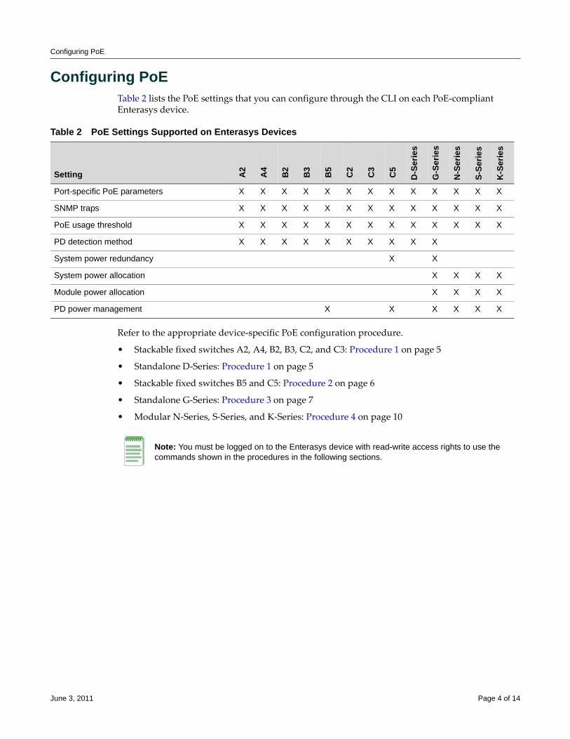
Configuring PoE
Configuring PoETable 2 lists the PoE settings that you can configure through the CLI on each PoE‐compliant Enterasys device.
Refer to the appropriate device‐specific PoE configuration procedure.
• Stackable fixed switches A2, A4, B2, B3, C2, and C3: Procedure 1 on page 5
• Standalone D‐Series: Procedure 1 on page 5
• Stackable fixed switches B5 and C5: Procedure 2 on page 6
• Standalone G‐Series: Procedure 3 on page 7
• Modular N‐Series, S‐Series, and K‐Series: Procedure 4 on page 10
Table 2 PoE Settings Supported on Enterasys Devices
Setting A2
A4
B2
B3
B5
C2
C3
C5
D-S
erie
s
G-S
erie
s
N-S
erie
s
S-Se
ries
K-S
erie
s
Port-specific PoE parameters X X X X X X X X X X X X X
SNMP traps X X X X X X X X X X X X X
PoE usage threshold X X X X X X X X X X X X X
PD detection method X X X X X X X X X X
System power redundancy X X
System power allocation X X X X
Module power allocation X X X X
PD power management X X X X X X
Note: You must be logged on to the Enterasys device with read-write access rights to use the commands shown in the procedures in the following sections.
June 3, 2011 Page 4 of 14
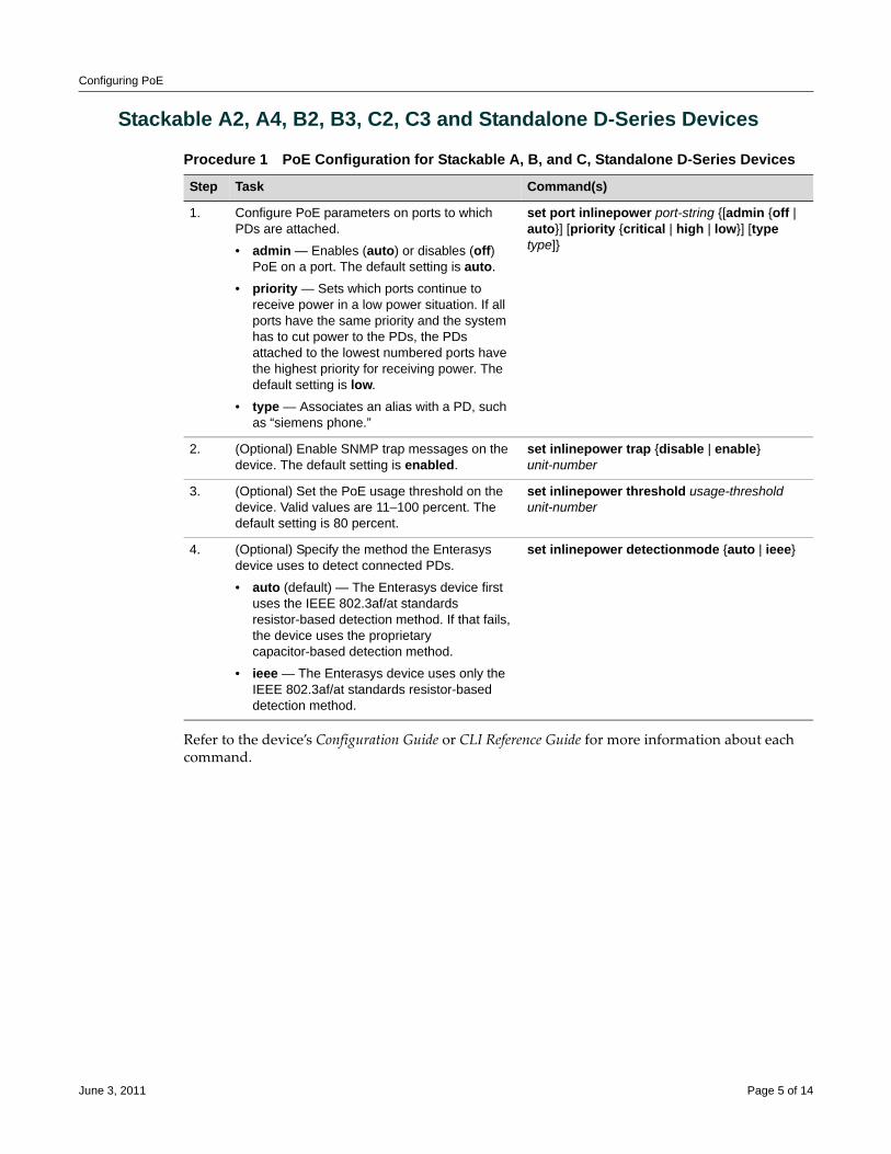
Configuring PoE
Stackable A2, A4, B2, B3, C2, C3 and Standalone D-Series Devices
Refer to the device’s Configuration Guide or CLI Reference Guide for more information about each command.
Procedure 1 PoE Configuration for Stackable A, B, and C, Standalone D-Series Devices
Step Task Command(s)
1. Configure PoE parameters on ports to which PDs are attached.
• admin — Enables (auto) or disables (off) PoE on a port. The default setting is auto.
• priority — Sets which ports continue to receive power in a low power situation. If all ports have the same priority and the system has to cut power to the PDs, the PDs attached to the lowest numbered ports have the highest priority for receiving power. The default setting is low.
• type — Associates an alias with a PD, such as “siemens phone.”
set port inlinepower port-string {[admin {off | auto}] [priority {critical | high | low}] [type type]}
2. (Optional) Enable SNMP trap messages on the device. The default setting is enabled.
set inlinepower trap {disable | enable} unit-number
3. (Optional) Set the PoE usage threshold on the device. Valid values are 11–100 percent. The default setting is 80 percent.
set inlinepower threshold usage-threshold unit-number
4. (Optional) Specify the method the Enterasys device uses to detect connected PDs.
• auto (default) — The Enterasys device first uses the IEEE 802.3af/at standards resistor-based detection method. If that fails, the device uses the proprietary capacitor-based detection method.
• ieee — The Enterasys device uses only the IEEE 802.3af/at standards resistor-based detection method.
set inlinepower detectionmode {auto | ieee}
June 3, 2011 Page 5 of 14
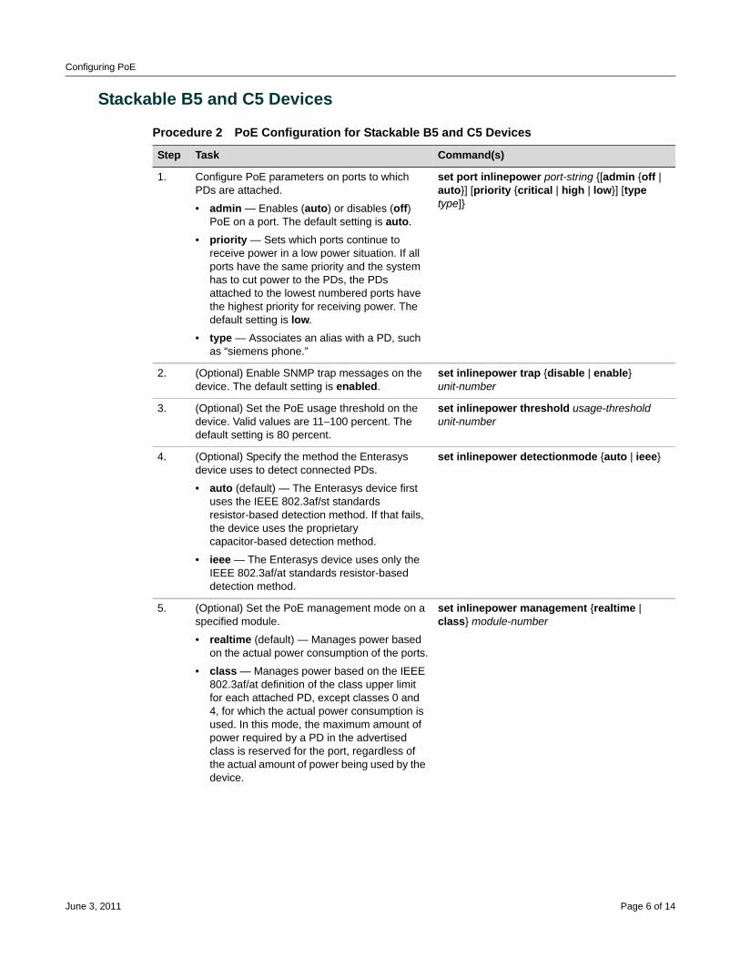
Configuring PoE
Stackable B5 and C5 Devices
Procedure 2 PoE Configuration for Stackable B5 and C5 Devices
Step Task Command(s)
1. Configure PoE parameters on ports to which PDs are attached.
• admin — Enables (auto) or disables (off) PoE on a port. The default setting is auto.
• priority — Sets which ports continue to receive power in a low power situation. If all ports have the same priority and the system has to cut power to the PDs, the PDs attached to the lowest numbered ports have the highest priority for receiving power. The default setting is low.
• type — Associates an alias with a PD, such as “siemens phone.”
set port inlinepower port-string {[admin {off | auto}] [priority {critical | high | low}] [type type]}
2. (Optional) Enable SNMP trap messages on the device. The default setting is enabled.
set inlinepower trap {disable | enable} unit-number
3. (Optional) Set the PoE usage threshold on the device. Valid values are 11–100 percent. The default setting is 80 percent.
set inlinepower threshold usage-threshold unit-number
4. (Optional) Specify the method the Enterasys device uses to detect connected PDs.
• auto (default) — The Enterasys device first uses the IEEE 802.3af/st standards resistor-based detection method. If that fails, the device uses the proprietary capacitor-based detection method.
• ieee — The Enterasys device uses only the IEEE 802.3af/at standards resistor-based detection method.
set inlinepower detectionmode {auto | ieee}
5. (Optional) Set the PoE management mode on a specified module.
• realtime (default) — Manages power based on the actual power consumption of the ports.
• class — Manages power based on the IEEE 802.3af/at definition of the class upper limit for each attached PD, except classes 0 and 4, for which the actual power consumption is used. In this mode, the maximum amount of power required by a PD in the advertised class is reserved for the port, regardless of the actual amount of power being used by the device.
set inlinepower management {realtime | class} module-number
June 3, 2011 Page 6 of 14
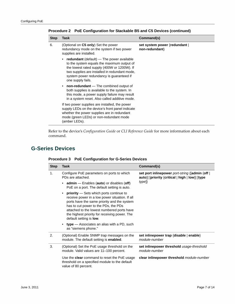
Configuring PoE
Refer to the device’s Configuration Guide or CLI Reference Guide for more information about each command.
G-Series Devices
6. (Optional on C5 only) Set the power redundancy mode on the system if two power supplies are installed.
• redundant (default) — The power available to the system equals the maximum output of the lowest rated supply (400W or 1200W). If two supplies are installed in redundant mode, system power redundancy is guaranteed if one supply fails.
• non-redundant — The combined output of both supplies is available to the system. In this mode, a power supply failure may result in a system reset. Also called additive mode.
If two power supplies are installed, the power supply LEDs on the device’s front panel indicate whether the power supplies are in redundant mode (green LEDs) or non-redundant mode (amber LEDs).
set system power {redundant | non-redundant}
Procedure 2 PoE Configuration for Stackable B5 and C5 Devices (continued)
Step Task Command(s)
Procedure 3 PoE Configuration for G-Series Devices
Step Task Command(s)
1. Configure PoE parameters on ports to which PDs are attached.
• admin — Enables (auto) or disables (off) PoE on a port. The default setting is auto.
• priority — Sets which ports continue to receive power in a low power situation. If all ports have the same priority and the system has to cut power to the PDs, the PDs attached to the lowest numbered ports have the highest priority for receiving power. The default setting is low.
• type — Associates an alias with a PD, such as “siemens phone.”
set port inlinepower port-string {[admin {off | auto}] [priority {critical | high | low}] [type type]}
2. (Optional) Enable SNMP trap messages on the module. The default setting is enabled.
set inlinepower trap {disable | enable} module-number
3. (Optional) Set the PoE usage threshold on the module. Valid values are 11–100 percent.
set inlinepower threshold usage-threshold module-number
Use the clear command to reset the PoE usage threshold on a specified module to the default value of 80 percent.
clear inlinepower threshold module-number
June 3, 2011 Page 7 of 14
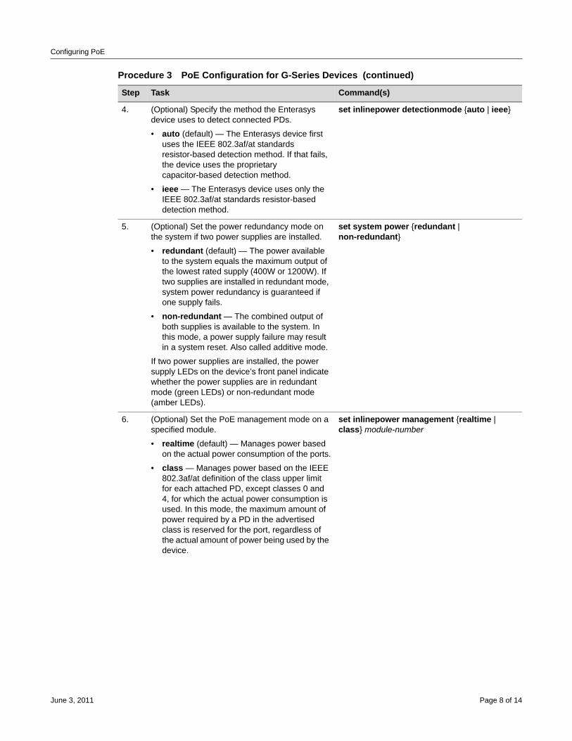
Configuring PoE
4. (Optional) Specify the method the Enterasys device uses to detect connected PDs.
• auto (default) — The Enterasys device first uses the IEEE 802.3af/at standards resistor-based detection method. If that fails, the device uses the proprietary capacitor-based detection method.
• ieee — The Enterasys device uses only the IEEE 802.3af/at standards resistor-based detection method.
set inlinepower detectionmode {auto | ieee}
5. (Optional) Set the power redundancy mode on the system if two power supplies are installed.
• redundant (default) — The power available to the system equals the maximum output of the lowest rated supply (400W or 1200W). If two supplies are installed in redundant mode, system power redundancy is guaranteed if one supply fails.
• non-redundant — The combined output of both supplies is available to the system. In this mode, a power supply failure may result in a system reset. Also called additive mode.
If two power supplies are installed, the power supply LEDs on the device’s front panel indicate whether the power supplies are in redundant mode (green LEDs) or non-redundant mode (amber LEDs).
set system power {redundant | non-redundant}
6. (Optional) Set the PoE management mode on a specified module.
• realtime (default) — Manages power based on the actual power consumption of the ports.
• class — Manages power based on the IEEE 802.3af/at definition of the class upper limit for each attached PD, except classes 0 and 4, for which the actual power consumption is used. In this mode, the maximum amount of power required by a PD in the advertised class is reserved for the port, regardless of the actual amount of power being used by the device.
set inlinepower management {realtime | class} module-number
Procedure 3 PoE Configuration for G-Series Devices (continued)
Step Task Command(s)
June 3, 2011 Page 8 of 14
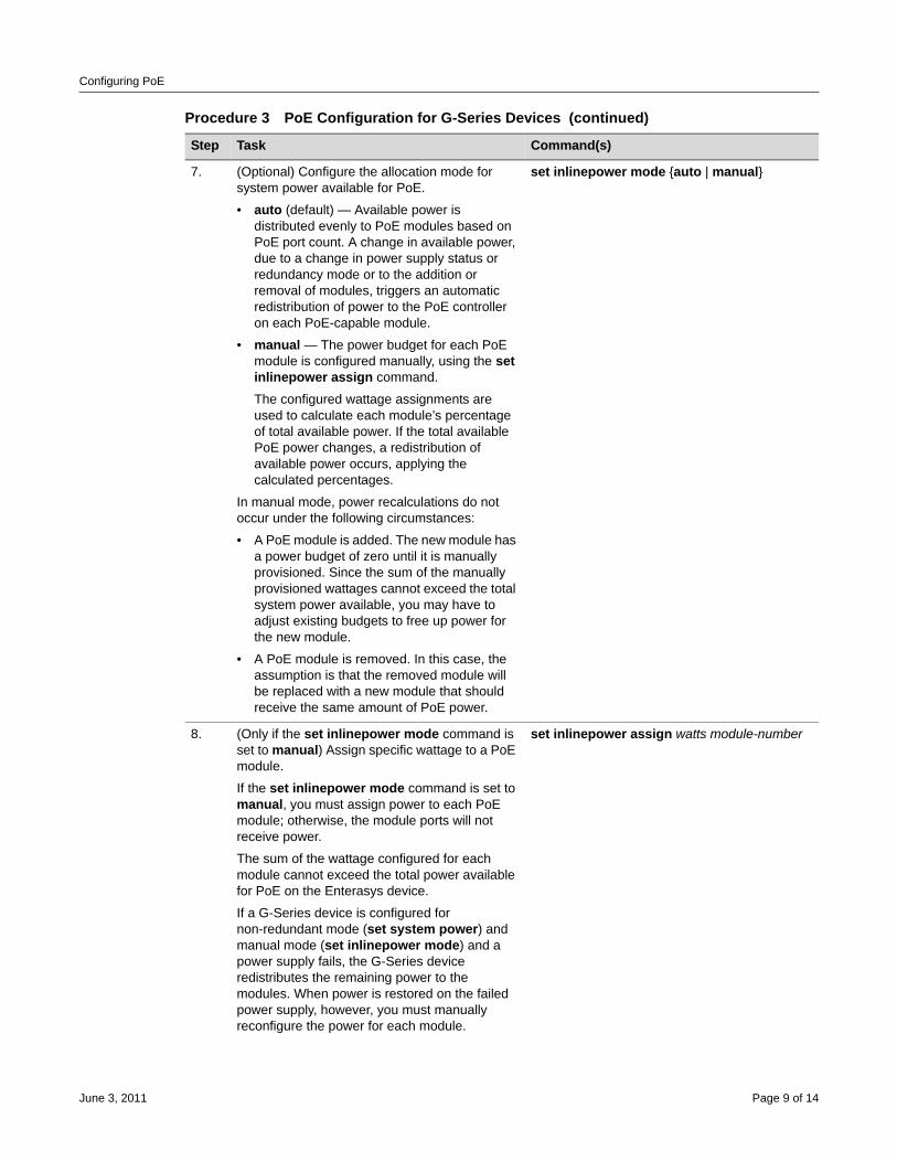
Configuring PoE
7. (Optional) Configure the allocation mode for system power available for PoE.
• auto (default) — Available power is distributed evenly to PoE modules based on PoE port count. A change in available power, due to a change in power supply status or redundancy mode or to the addition or removal of modules, triggers an automatic redistribution of power to the PoE controller on each PoE-capable module.
• manual — The power budget for each PoE module is configured manually, using the set inlinepower assign command.
The configured wattage assignments are used to calculate each module’s percentage of total available power. If the total available PoE power changes, a redistribution of available power occurs, applying the calculated percentages.
In manual mode, power recalculations do not occur under the following circumstances:
• A PoE module is added. The new module has a power budget of zero until it is manually provisioned. Since the sum of the manually provisioned wattages cannot exceed the total system power available, you may have to adjust existing budgets to free up power for the new module.
• A PoE module is removed. In this case, the assumption is that the removed module will be replaced with a new module that should receive the same amount of PoE power.
set inlinepower mode {auto | manual}
8. (Only if the set inlinepower mode command is set to manual) Assign specific wattage to a PoE module.
If the set inlinepower mode command is set to manual, you must assign power to each PoE module; otherwise, the module ports will not receive power.
The sum of the wattage configured for each module cannot exceed the total power available for PoE on the Enterasys device.
If a G-Series device is configured for non-redundant mode (set system power) and manual mode (set inlinepower mode) and a power supply fails, the G-Series device redistributes the remaining power to the modules. When power is restored on the failed power supply, however, you must manually reconfigure the power for each module.
set inlinepower assign watts module-number
Procedure 3 PoE Configuration for G-Series Devices (continued)
Step Task Command(s)
June 3, 2011 Page 9 of 14
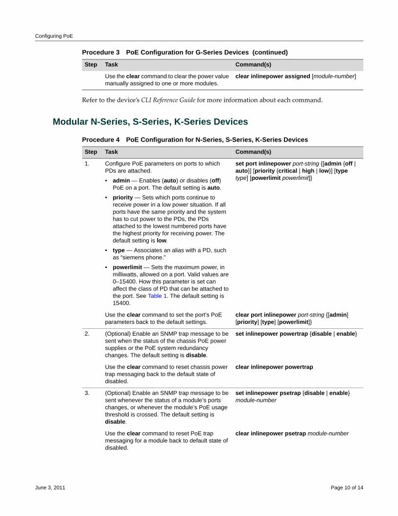
Configuring PoE
Refer to the device’s CLI Reference Guide for more information about each command.
Modular N-Series, S-Series, K-Series Devices
Use the clear command to clear the power value manually assigned to one or more modules.
clear inlinepower assigned [module-number]
Procedure 3 PoE Configuration for G-Series Devices (continued)
Step Task Command(s)
Procedure 4 PoE Configuration for N-Series, S-Series, K-Series Devices
Step Task Command(s)
1. Configure PoE parameters on ports to which PDs are attached.
• admin — Enables (auto) or disables (off) PoE on a port. The default setting is auto.
• priority — Sets which ports continue to receive power in a low power situation. If all ports have the same priority and the system has to cut power to the PDs, the PDs attached to the lowest numbered ports have the highest priority for receiving power. The default setting is low.
• type — Associates an alias with a PD, such as “siemens phone.”
• powerlimit — Sets the maximum power, in milliwatts, allowed on a port. Valid values are 0–15400. How this parameter is set can affect the class of PD that can be attached to the port. See Table 1. The default setting is 15400.
set port inlinepower port-string {[admin {off | auto}] [priority {critical | high | low}] [type type] [powerlimit powerlimit]}
Use the clear command to set the port’s PoE parameters back to the default settings.
clear port inlinepower port-string {[admin] [priority] [type] [powerlimit]}
2. (Optional) Enable an SNMP trap message to be sent when the status of the chassis PoE power supplies or the PoE system redundancy changes. The default setting is disable.
set inlinepower powertrap {disable | enable}
Use the clear command to reset chassis power trap messaging back to the default state of disabled.
clear inlinepower powertrap
3. (Optional) Enable an SNMP trap message to be sent whenever the status of a module’s ports changes, or whenever the module’s PoE usage threshold is crossed. The default setting is disable.
set inlinepower psetrap {disable | enable} module-number
Use the clear command to reset PoE trap messaging for a module back to default state of disabled.
clear inlinepower psetrap module-number
June 3, 2011 Page 10 of 14
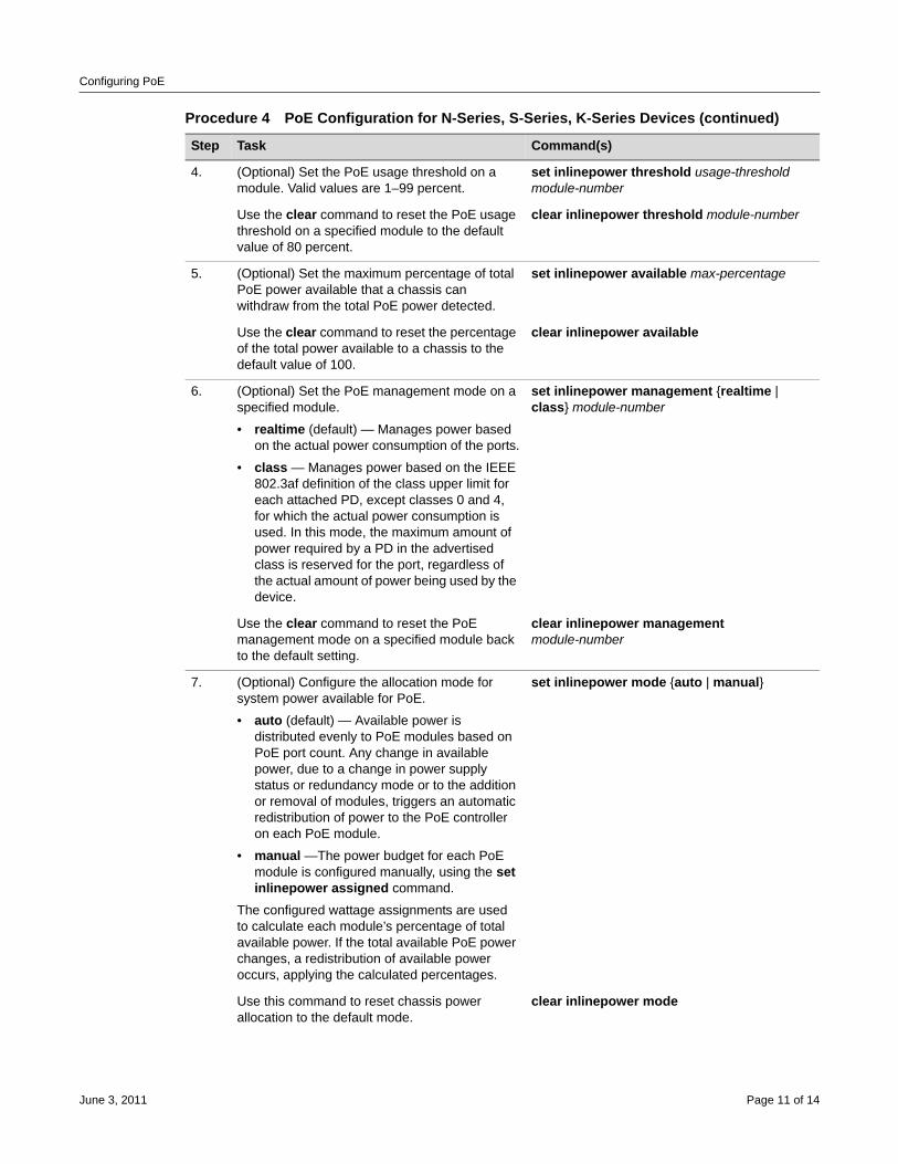
Configuring PoE
4. (Optional) Set the PoE usage threshold on a module. Valid values are 1–99 percent.
set inlinepower threshold usage-threshold module-number
Use the clear command to reset the PoE usage threshold on a specified module to the default value of 80 percent.
clear inlinepower threshold module-number
5. (Optional) Set the maximum percentage of total PoE power available that a chassis can withdraw from the total PoE power detected.
set inlinepower available max-percentage
Use the clear command to reset the percentage of the total power available to a chassis to the default value of 100.
clear inlinepower available
6. (Optional) Set the PoE management mode on a specified module.
• realtime (default) — Manages power based on the actual power consumption of the ports.
• class — Manages power based on the IEEE 802.3af definition of the class upper limit for each attached PD, except classes 0 and 4, for which the actual power consumption is used. In this mode, the maximum amount of power required by a PD in the advertised class is reserved for the port, regardless of the actual amount of power being used by the device.
set inlinepower management {realtime | class} module-number
Use the clear command to reset the PoE management mode on a specified module back to the default setting.
clear inlinepower management module-number
7. (Optional) Configure the allocation mode for system power available for PoE.
• auto (default) — Available power is distributed evenly to PoE modules based on PoE port count. Any change in available power, due to a change in power supply status or redundancy mode or to the addition or removal of modules, triggers an automatic redistribution of power to the PoE controller on each PoE module.
• manual —The power budget for each PoE module is configured manually, using the set inlinepower assigned command.
The configured wattage assignments are used to calculate each module’s percentage of total available power. If the total available PoE power changes, a redistribution of available power occurs, applying the calculated percentages.
set inlinepower mode {auto | manual}
Use this command to reset chassis power allocation to the default mode.
clear inlinepower mode
Procedure 4 PoE Configuration for N-Series, S-Series, K-Series Devices (continued)
Step Task Command(s)
June 3, 2011 Page 11 of 14
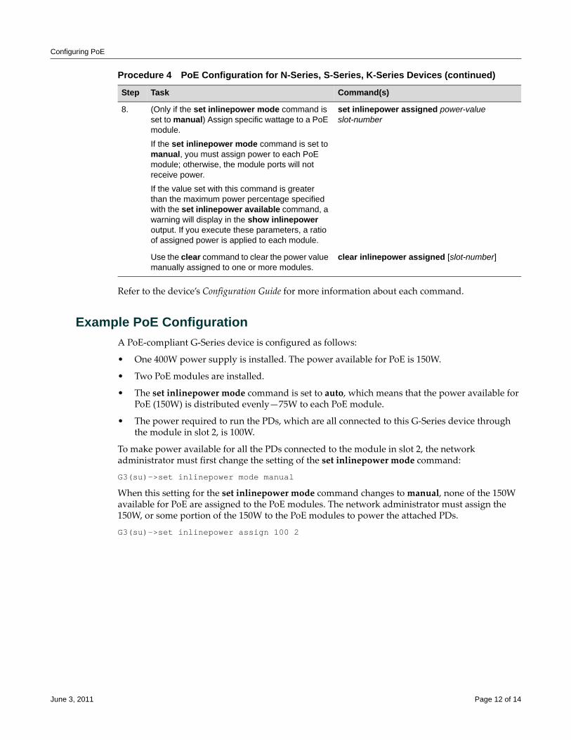
Configuring PoE
Refer to the device’s Configuration Guide for more information about each command.
Example PoE ConfigurationA PoE‐compliant G‐Series device is configured as follows:
• One 400W power supply is installed. The power available for PoE is 150W.
• Two PoE modules are installed.
• The set inlinepower mode command is set to auto, which means that the power available for PoE (150W) is distributed evenly—75W to each PoE module.
• The power required to run the PDs, which are all connected to this G‐Series device through the module in slot 2, is 100W.
To make power available for all the PDs connected to the module in slot 2, the network administrator must first change the setting of the set inlinepower mode command:
G3(su)->set inlinepower mode manual
When this setting for the set inlinepower mode command changes to manual, none of the 150W available for PoE are assigned to the PoE modules. The network administrator must assign the 150W, or some portion of the 150W to the PoE modules to power the attached PDs.
G3(su)->set inlinepower assign 100 2
8. (Only if the set inlinepower mode command is set to manual) Assign specific wattage to a PoE module.
If the set inlinepower mode command is set to manual, you must assign power to each PoE module; otherwise, the module ports will not receive power.
If the value set with this command is greater than the maximum power percentage specified with the set inlinepower available command, a warning will display in the show inlinepower output. If you execute these parameters, a ratio of assigned power is applied to each module.
set inlinepower assigned power-value slot-number
Use the clear command to clear the power value manually assigned to one or more modules.
clear inlinepower assigned [slot-number]
Procedure 4 PoE Configuration for N-Series, S-Series, K-Series Devices (continued)
Step Task Command(s)
June 3, 2011 Page 12 of 14
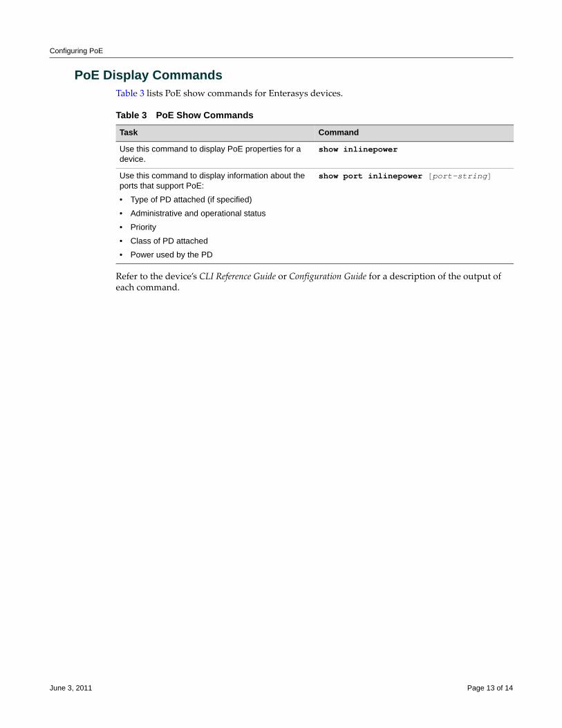
Configuring PoE
PoE Display CommandsTable 3 lists PoE show commands for Enterasys devices.
Refer to the device’s CLI Reference Guide or Configuration Guide for a description of the output of each command.
Table 3 PoE Show Commands
Task Command
Use this command to display PoE properties for a device.
show inlinepower
Use this command to display information about the ports that support PoE:
• Type of PD attached (if specified)
• Administrative and operational status
• Priority
• Class of PD attached
• Power used by the PD
show port inlinepower [port-string]
June 3, 2011 Page 13 of 14
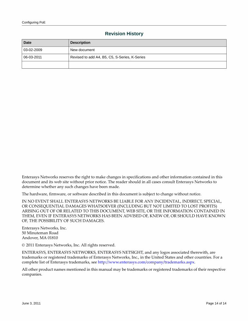
Configuring PoE
Enterasys Networks reserves the right to make changes in specifications and other information contained in this document and its web site without prior notice. The reader should in all cases consult Enterasys Networks to determine whether any such changes have been made.
The hardware, firmware, or software described in this document is subject to change without notice.
IN NO EVENT SHALL ENTERASYS NETWORKS BE LIABLE FOR ANY INCIDENTAL, INDIRECT, SPECIAL, OR CONSEQUENTIAL DAMAGES WHATSOEVER (INCLUDING BUT NOT LIMITED TO LOST PROFITS) ARISING OUT OF OR RELATED TO THIS DOCUMENT, WEB SITE, OR THE INFORMATION CONTAINED IN THEM, EVEN IF ENTERASYS NETWORKS HAS BEEN ADVISED OF, KNEW OF, OR SHOULD HAVE KNOWN OF, THE POSSIBILITY OF SUCH DAMAGES.
Enterasys Networks, Inc.50 Minuteman RoadAndover, MA 01810
© 2011 Enterasys Networks, Inc. All rights reserved.
ENTERASYS, ENTERASYS NETWORKS, ENTERASYS NETSIGHT, and any logos associated therewith, are trademarks or registered trademarks of Enterasys Networks, Inc., in the United States and other countries. For a complete list of Enterasys trademarks, see http://www.enterasys.com/company/trademarks.aspx.
All other product names mentioned in this manual may be trademarks or registered trademarks of their respective companies.
Revision History
Date Description
03-02-2009 New document
06-03-2011 Revised to add A4, B5, C5, S-Series, K-Series
June 3, 2011 Page 14 of 14
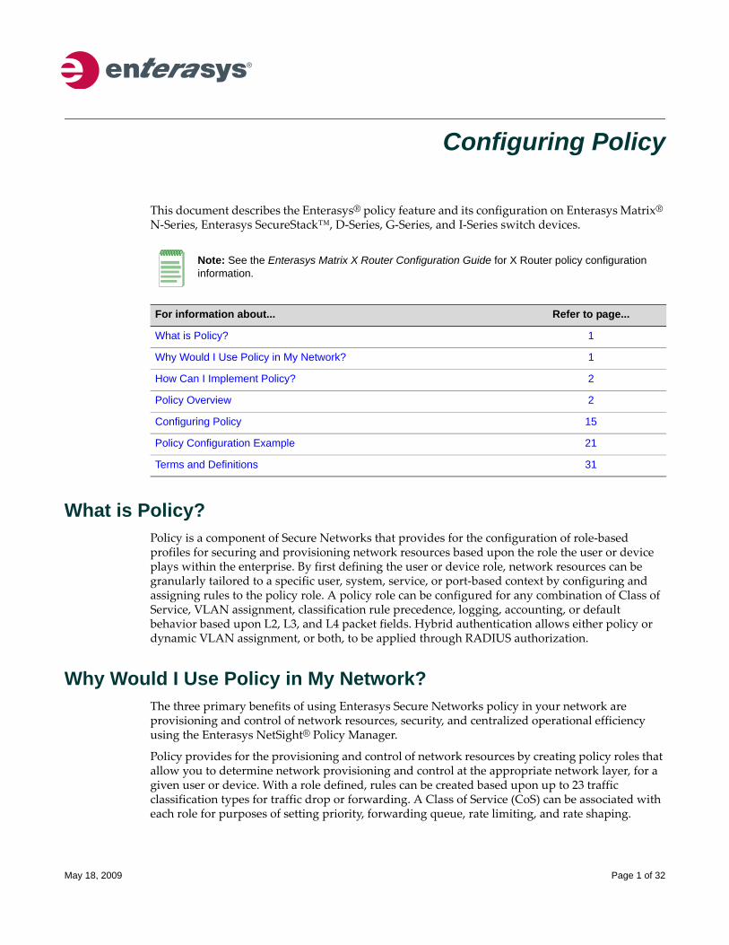
Configuring Policy
This document describes the Enterasys® policy feature and its configuration on Enterasys Matrix® N‐Series, Enterasys SecureStack™, D‐Series, G‐Series, and I‐Series switch devices.
What is Policy?Policy is a component of Secure Networks that provides for the configuration of role‐based profiles for securing and provisioning network resources based upon the role the user or device plays within the enterprise. By first defining the user or device role, network resources can be granularly tailored to a specific user, system, service, or port‐based context by configuring and assigning rules to the policy role. A policy role can be configured for any combination of Class of Service, VLAN assignment, classification rule precedence, logging, accounting, or default behavior based upon L2, L3, and L4 packet fields. Hybrid authentication allows either policy or dynamic VLAN assignment, or both, to be applied through RADIUS authorization.
Why Would I Use Policy in My Network?The three primary benefits of using Enterasys Secure Networks policy in your network are provisioning and control of network resources, security, and centralized operational efficiency using the Enterasys NetSight® Policy Manager.
Policy provides for the provisioning and control of network resources by creating policy roles that allow you to determine network provisioning and control at the appropriate network layer, for a given user or device. With a role defined, rules can be created based upon up to 23 traffic classification types for traffic drop or forwarding. A Class of Service (CoS) can be associated with each role for purposes of setting priority, forwarding queue, rate limiting, and rate shaping.
Note: See the Enterasys Matrix X Router Configuration Guide for X Router policy configuration information.
For information about... Refer to page...
What is Policy? 1
Why Would I Use Policy in My Network? 1
How Can I Implement Policy? 2
Policy Overview 2
Configuring Policy 15
Policy Configuration Example 21
Terms and Definitions 31
May 18, 2009 Page 1 of 32
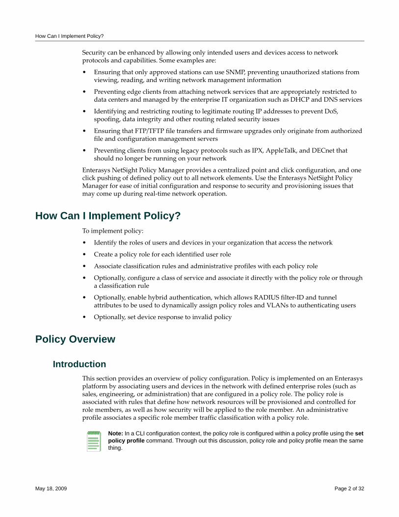
How Can I Implement Policy?
Security can be enhanced by allowing only intended users and devices access to network protocols and capabilities. Some examples are:
• Ensuring that only approved stations can use SNMP, preventing unauthorized stations from viewing, reading, and writing network management information
• Preventing edge clients from attaching network services that are appropriately restricted to data centers and managed by the enterprise IT organization such as DHCP and DNS services
• Identifying and restricting routing to legitimate routing IP addresses to prevent DoS, spoofing, data integrity and other routing related security issues
• Ensuring that FTP/TFTP file transfers and firmware upgrades only originate from authorized file and configuration management servers
• Preventing clients from using legacy protocols such as IPX, AppleTalk, and DECnet that should no longer be running on your network
Enterasys NetSight Policy Manager provides a centralized point and click configuration, and one click pushing of defined policy out to all network elements. Use the Enterasys NetSight Policy Manager for ease of initial configuration and response to security and provisioning issues that may come up during real‐time network operation.
How Can I Implement Policy?To implement policy:
• Identify the roles of users and devices in your organization that access the network
• Create a policy role for each identified user role
• Associate classification rules and administrative profiles with each policy role
• Optionally, configure a class of service and associate it directly with the policy role or through a classification rule
• Optionally, enable hybrid authentication, which allows RADIUS filter‐ID and tunnel attributes to be used to dynamically assign policy roles and VLANs to authenticating users
• Optionally, set device response to invalid policy
Policy Overview
IntroductionThis section provides an overview of policy configuration. Policy is implemented on an Enterasys platform by associating users and devices in the network with defined enterprise roles (such as sales, engineering, or administration) that are configured in a policy role. The policy role is associated with rules that define how network resources will be provisioned and controlled for role members, as well as how security will be applied to the role member. An administrative profile associates a specific role member traffic classification with a policy role.
Note: In a CLI configuration context, the policy role is configured within a policy profile using the set policy profile command. Through out this discussion, policy role and policy profile mean the same thing.
May 18, 2009 Page 2 of 32
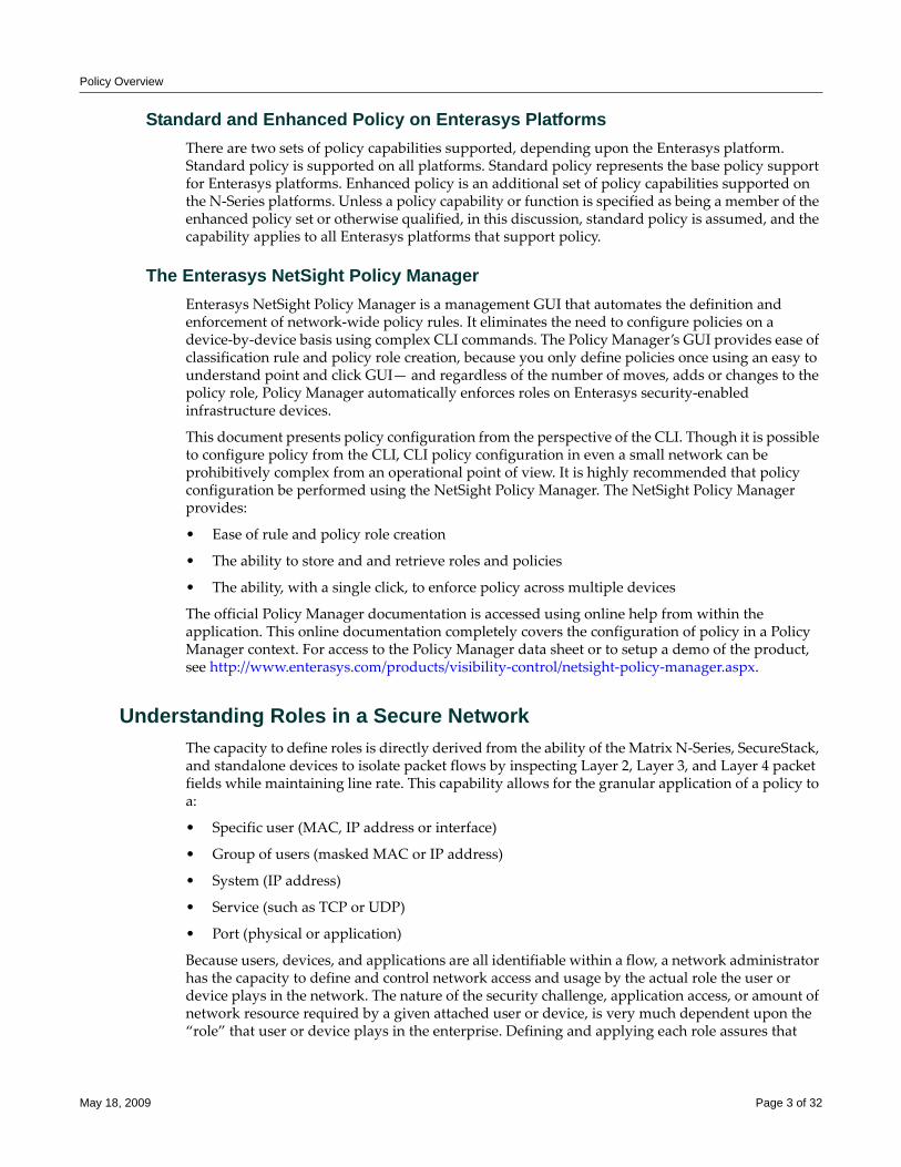
Policy Overview
Standard and Enhanced Policy on Enterasys PlatformsThere are two sets of policy capabilities supported, depending upon the Enterasys platform. Standard policy is supported on all platforms. Standard policy represents the base policy support for Enterasys platforms. Enhanced policy is an additional set of policy capabilities supported on the N‐Series platforms. Unless a policy capability or function is specified as being a member of the enhanced policy set or otherwise qualified, in this discussion, standard policy is assumed, and the capability applies to all Enterasys platforms that support policy.
The Enterasys NetSight Policy ManagerEnterasys NetSight Policy Manager is a management GUI that automates the definition and enforcement of network‐wide policy rules. It eliminates the need to configure policies on a device‐by‐device basis using complex CLI commands. The Policy Manager’s GUI provides ease of classification rule and policy role creation, because you only define policies once using an easy to understand point and click GUI— and regardless of the number of moves, adds or changes to the policy role, Policy Manager automatically enforces roles on Enterasys security‐enabled infrastructure devices.
This document presents policy configuration from the perspective of the CLI. Though it is possible to configure policy from the CLI, CLI policy configuration in even a small network can be prohibitively complex from an operational point of view. It is highly recommended that policy configuration be performed using the NetSight Policy Manager. The NetSight Policy Manager provides:
• Ease of rule and policy role creation
• The ability to store and and retrieve roles and policies
• The ability, with a single click, to enforce policy across multiple devices
The official Policy Manager documentation is accessed using online help from within the application. This online documentation completely covers the configuration of policy in a Policy Manager context. For access to the Policy Manager data sheet or to setup a demo of the product, see http://www.enterasys.com/products/visibility‐control/netsight‐policy‐manager.aspx.
Understanding Roles in a Secure Network The capacity to define roles is directly derived from the ability of the Matrix N‐Series, SecureStack, and standalone devices to isolate packet flows by inspecting Layer 2, Layer 3, and Layer 4 packet fields while maintaining line rate. This capability allows for the granular application of a policy to a:
• Specific user (MAC, IP address or interface)
• Group of users (masked MAC or IP address)
• System (IP address)
• Service (such as TCP or UDP)
• Port (physical or application)
Because users, devices, and applications are all identifiable within a flow, a network administrator has the capacity to define and control network access and usage by the actual role the user or device plays in the network. The nature of the security challenge, application access, or amount of network resource required by a given attached user or device, is very much dependent upon the “role” that user or device plays in the enterprise. Defining and applying each role assures that
May 18, 2009 Page 3 of 32
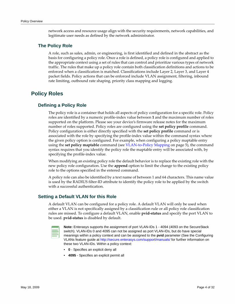
Policy Overview
network access and resource usage align with the security requirements, network capabilities, and legitimate user needs as defined by the network administrator.
The Policy RoleA role, such as sales, admin, or engineering, is first identified and defined in the abstract as the basis for configuring a policy role. Once a role is defined, a policy role is configured and applied to the appropriate context using a set of rules that can control and prioritize various types of network traffic. The rules that make up a policy role contain both classification definitions and actions to be enforced when a classification is matched. Classifications include Layer 2, Layer 3, and Layer 4 packet fields. Policy actions that can be enforced include VLAN assignment, filtering, inbound rate limiting, outbound rate shaping, priority class mapping and logging.
Policy Roles
Defining a Policy RoleThe policy role is a container that holds all aspects of policy configuration for a specific role. Policy roles are identified by a numeric profile‐index value between 1 and the maximum number of roles supported on the platform. Please see your device’s firmware release notes for the maximum number of roles supported. Policy roles are configured using the set policy profile command. Policy configuration is either directly specified with the set policy profile command or is associated with the role by specifying the profile‐index value within the command syntax where the given policy option is configured. For example, when configuring a policy maptable entry using the set policy maptable command (see VLAN‐to‐Policy Mapping on page 5), the command syntax requires that you identify the policy role the maptable entry will be associated with, by specifying the profile‐index value.
When modifying an existing policy role the default behavior is to replace the existing role with the new policy role configuration. Use the append option to limit the change to the existing policy role to the options specified in the entered command.
A policy role can also be identified by a text name of between 1 and 64 characters. This name value is used by the RADIUS filter‐ID attribute to identify the policy role to be applied by the switch with a successful authentication.
Setting a Default VLAN for this RoleA default VLAN can be configured for a policy role. A default VLAN will only be used when either a VLAN is not specifically assigned by a classification rule or all policy role classification rules are missed. To configure a default VLAN, enable pvid‐status and specify the port VLAN to be used. pvid‐status is disabled by default.
Note: Enterasys supports the assignment of port VLAN-IDs 1 - 4094 (4093 on the SecureStack switch). VLAN-IDs 0 and 4095 can not be assigned as port VLAN-IDs, but do have special meanings within a policy context and can be assigned to the pvid parameter (See the Configuring VLANs feature guide at http://secure.enterasys.com/support/manuals/ for further information on these two VLAN-IDs. Within a policy context:
• 0 - Specifies an explicit deny all
• 4095 - Specifies an explicit permit all
May 18, 2009 Page 4 of 32
Policy Overview
Assigning a Class of Service to this RoleHow a packet is treated as it transits the link can be configured in the Class of Service (CoS). It is through a CoS that Quality of Service (QoS) is implemented. A CoS can be configured for the following values:
• 802.1p priority
• IP Type of Service (ToS) rewrite value
• Priority Transmit Queue (TxQ) along with a forwarding behavior
• Inbound and outbound rate limiter per transmit queue
• Outbound rate shaper per transmit queue
CoS configurations are identified by a numeric value between 0 ‐ 255. 0 ‐ 7 are fixed 802.1p CoS configurations. CoS configurations 8 ‐ 255 are user configurable. Policy uses the cos option followed by the CoS configuration ID value to associate a CoS with a policy role.
QoS configuration details are beyond the scope of this feature guide. See the QoS Configuration feature guide located at http://secure.enterasys.com/support/manuals/ for a complete discussion of QoS configuration.
Adding Tagged, Untagged, and Forbidden Ports to the VLAN Egress ListsThe VLAN Egress list contains a list of ports that a frame for this VLAN can exit. Specified ports are automatically assigned to the VLAN egress list for this policy role as tagged, untagged, or forbidden.
Overwriting VLAN Tags Priority and Classification Settings
Enhanced PolicyTCI overwrite supports the application of rules to a policy role that overwrite the current user priority and other classification information in the VLAN tag’s TCI field. TCI overwrite must be enabled for both the policy role and the port the role is applied to.
Use the set policy profile tci‐overwrite command to enable TCI overwrite on a policy role.
Use the set port tcioverwrite command to enable TCI overwrite on the specified port.
VLAN-to-Policy Mapping
Enhanced PolicyVLAN‐to‐Policy mapping provides for the manual configuration of a VLAN‐to‐Policy association that creates a policy maptable entry between the specified VLAN and the specified policy role. A policy maptable holds the VLAN‐to‐Policy mappings. When an incoming tagged VLAN packet is seen by the switch, a lookup of the policy maptable determines whether a VLAN‐to‐policy mapping exists. If the mapping exists, the associated policy is applied to this packet.
This feature can be used at the distribution layer in environments where non‐policy capable edge switches are deployed and there is no possibility of applying Enterasys policy at the edge. Tagged frames received at the distribution layer interface for a VLAN with an entry in the policy maptable will have the associated policy applied to the frame.
May 18, 2009 Page 5 of 32
Policy Overview
Use the set policy maptable command specifying a single VLAN ID or range of IDs and the policy profile‐index to create a policy maptable entry.
Applying Policy Using the RADIUS Response AttributesIf an authentication method that requires communication with an authentication server is configured for a user, the RADIUS filter‐ID attribute can be used to dynamically assign a policy role to the authenticating user. Supported RADIUS attributes are sent to the switch in the RADIUS access‐accept message. The RADIUS filter‐ID can also be applied in hybrid authentication mode. Hybrid authentication mode determines how the RADIUS filter‐ID and the three RFC 3580 VLAN tunnel attributes (VLAN Authorization), when either or all are included in the RADIUS access‐accept message, will be handled by the switch. The three VLAN tunnel attributes define the base VLAN‐ID to be applied to the user. In either case, conflict resolution between RADIUS attributes is provided by the maptable response feature.
Please see the Configuring User Authentication feature guide located at http://secure.enterasys.com/support/manuals/ for a discussion of RADIUS configuration, the RADIUS filter‐ID, and VLAN authorization.
Use the policy option of the set policy maptable response command to configure the switch to dynamically assign a policy using the RADIUS filter‐ID in the RADIUS response message.
Applying Policy Using Hybrid Authentication Mode
Enhanced Policy
Hybrid authentication is an authentication capability that allows the switch to use both the filter‐ID and tunnel attributes in the RADIUS response message to determine how to treat the authenticating user.
Hybrid authentication is configured by specifying the both option in the set policy maptable command. The both option:
• Applies the VLAN tunnel attributes if they exist and the filter‐ID attribute does not
• Applies the filter‐ID attribute if it exists and the VLAN tunnel attributes do not
Note: VLAN-to-Policy mapping is supported on the B3, C3, and G3 switches for firmware releases 6.3 and greater.
Note: VLAN-to-policy mapping to maptable response configuration behavior is as follows:
• If the RADIUS response is set to policy, any VLAN-to-policy maptable configuration is ignored for all platforms.
• If the RADIUS response is set to tunnel, VLAN-to-policy mapping can occur on an N-Series platform; VLAN-to-policy mapping will not occur on a SecureStack or standalone platform.
• If the RADIUS response is set to both and both the filter-ID and tunnel attributes are present, VLAN-to-policy mapping configuration is ignored. See the “When Policy Maptable Response is Both” section of the Configuring User Authentication feature guide for exceptions to this behavior.
Note: Hybrid authentication is an enhanced policy capability. For the B3, C3, and G3 platforms, hybrid authentication is supported for Releases 6.3 and greater.
May 18, 2009 Page 6 of 32
Policy Overview
• Applies both the filter‐ID and the VLAN tunnel attributes if all attributes exist
If all attributes exist, the following rules apply:
• The policy role will be enforced, with the exception that any port PVID specified in the role will be replaced with the VLAN tunnel attributes
• The policy map is ignored because the policy role is explicitly assigned
• VLAN classification rules are assigned as defined by the policy role
vlanauthorization must be enabled or the VLAN tunnel attributes are ignored and the default VLAN is used. Please see the Configuring User Authentication feature guide located at http://secure.enterasys.com/support/manuals/ for a complete VLAN Authorization discussion.
Hybrid Mode support eliminates the dependency of VLAN assignment based on roles. As a result, VLANs can be assigned via the tunnel‐private‐group‐ID, as defined per RFC3580, while assigning roles via the filter‐ID. This separation gives administrators more flexibility to segment their networks for efficiency beyond the role limits associated with the B3, C3, and G3 platforms.
Device Response to Invalid Policy
Enhanced PolicyThe action that the device should take when asked to apply an invalid or unknown policy can be specified. The available actions are:
• Ignore the result and search for the next policy assignment rule. If all rules are missed, the default policy is applied.
• Block traffic
• Forward traffic as if no policy has been assigned using 802.1D/Q rules
Use the set policy invalid action command to specify a default action to take when asked to apply an invalid or unknown policy.
Classification RulesClassification rules associate specific traffic classifications or policy behaviors with the policy role. There are two aspects of classification rule configuration:
• The association of a traffic classification with a policy role by assigning the traffic classification to an administrative profile.
• The assignment of policy rules that define desired policy behaviors for the specified traffic classification type.
Both the administrative profile and policy rules are associated with the policy role by specifying the admin‐pid option, in the case of an administrative profile, or a profile‐index value, in the case of the policy rule. Administrative profiles and policy rules are configured using the set policy rule command.
The administrative profile assigns a traffic classification to a policy role by using the admin‐profile option of the set policy rule command.
Note: Standard policy supports the VLAN tag traffic classification for administrative profiles. All other traffic classifications are enhanced policy in an administrative profile context. See Table 1 for a listing of supported traffic classifications.
May 18, 2009 Page 7 of 32
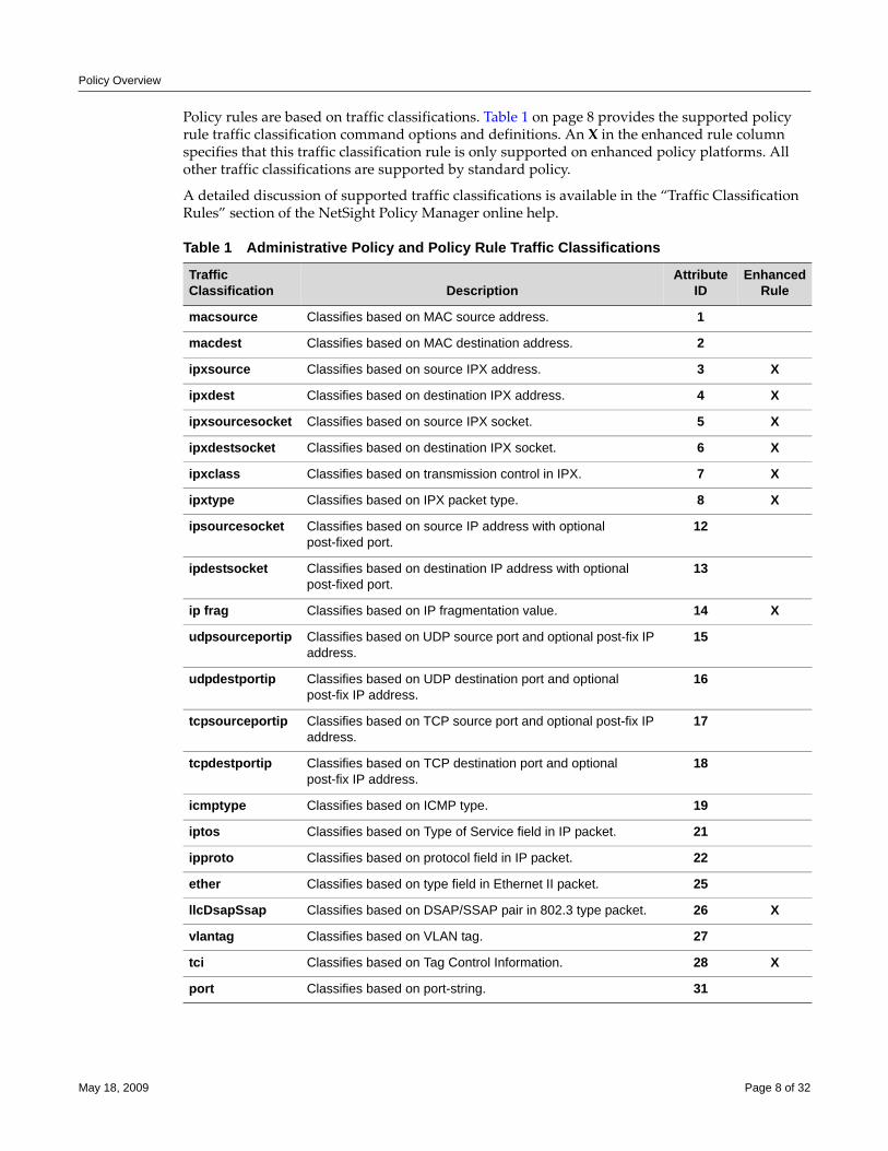
Policy Overview
Policy rules are based on traffic classifications. Table 1 on page 8 provides the supported policy rule traffic classification command options and definitions. An X in the enhanced rule column specifies that this traffic classification rule is only supported on enhanced policy platforms. All other traffic classifications are supported by standard policy.
A detailed discussion of supported traffic classifications is available in the “Traffic Classification Rules” section of the NetSight Policy Manager online help.
Table 1 Administrative Policy and Policy Rule Traffic Classifications
Traffic Classification Description
AttributeID
Enhanced Rule
macsource Classifies based on MAC source address. 1
macdest Classifies based on MAC destination address. 2
ipxsource Classifies based on source IPX address. 3 X
ipxdest Classifies based on destination IPX address. 4 X
ipxsourcesocket Classifies based on source IPX socket. 5 X
ipxdestsocket Classifies based on destination IPX socket. 6 X
ipxclass Classifies based on transmission control in IPX. 7 X
ipxtype Classifies based on IPX packet type. 8 X
ipsourcesocket Classifies based on source IP address with optional post-fixed port.
12
ipdestsocket Classifies based on destination IP address with optional post-fixed port.
13
ip frag Classifies based on IP fragmentation value. 14 X
udpsourceportip Classifies based on UDP source port and optional post-fix IP address.
15
udpdestportip Classifies based on UDP destination port and optional post-fix IP address.
16
tcpsourceportip Classifies based on TCP source port and optional post-fix IP address.
17
tcpdestportip Classifies based on TCP destination port and optional post-fix IP address.
18
icmptype Classifies based on ICMP type. 19
iptos Classifies based on Type of Service field in IP packet. 21
ipproto Classifies based on protocol field in IP packet. 22
ether Classifies based on type field in Ethernet II packet. 25
llcDsapSsap Classifies based on DSAP/SSAP pair in 802.3 type packet. 26 X
vlantag Classifies based on VLAN tag. 27
tci Classifies based on Tag Control Information. 28 X
port Classifies based on port-string. 31
May 18, 2009 Page 8 of 32
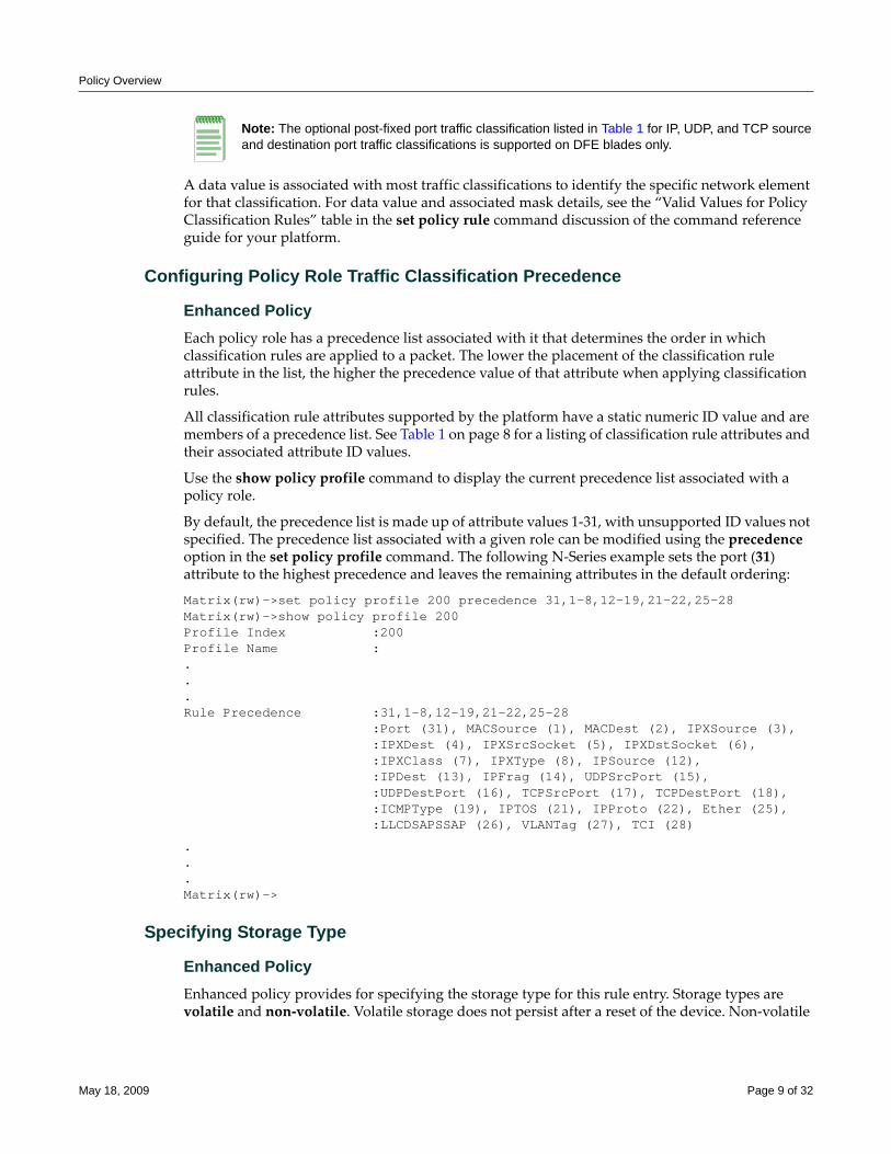
Policy Overview
A data value is associated with most traffic classifications to identify the specific network element for that classification. For data value and associated mask details, see the “Valid Values for Policy Classification Rules” table in the set policy rule command discussion of the command reference guide for your platform.
Configuring Policy Role Traffic Classification Precedence
Enhanced PolicyEach policy role has a precedence list associated with it that determines the order in which classification rules are applied to a packet. The lower the placement of the classification rule attribute in the list, the higher the precedence value of that attribute when applying classification rules.
All classification rule attributes supported by the platform have a static numeric ID value and are members of a precedence list. See Table 1 on page 8 for a listing of classification rule attributes and their associated attribute ID values.
Use the show policy profile command to display the current precedence list associated with a policy role.
By default, the precedence list is made up of attribute values 1‐31, with unsupported ID values not specified. The precedence list associated with a given role can be modified using the precedence option in the set policy profile command. The following N‐Series example sets the port (31) attribute to the highest precedence and leaves the remaining attributes in the default ordering:
Matrix(rw)->set policy profile 200 precedence 31,1-8,12-19,21-22,25-28Matrix(rw)->show policy profile 200Profile Index :200Profile Name : ...Rule Precedence :31,1-8,12-19,21-22,25-28
:Port (31), MACSource (1), MACDest (2), IPXSource (3),:IPXDest (4), IPXSrcSocket (5), IPXDstSocket (6), :IPXClass (7), IPXType (8), IPSource (12), :IPDest (13), IPFrag (14), UDPSrcPort (15), :UDPDestPort (16), TCPSrcPort (17), TCPDestPort (18), :ICMPType (19), IPTOS (21), IPProto (22), Ether (25), :LLCDSAPSSAP (26), VLANTag (27), TCI (28)
.
.
.Matrix(rw)->
Specifying Storage Type
Enhanced PolicyEnhanced policy provides for specifying the storage type for this rule entry. Storage types are volatile and non‐volatile. Volatile storage does not persist after a reset of the device. Non‐volatile
Note: The optional post-fixed port traffic classification listed in Table 1 for IP, UDP, and TCP source and destination port traffic classifications is supported on DFE blades only.
May 18, 2009 Page 9 of 32
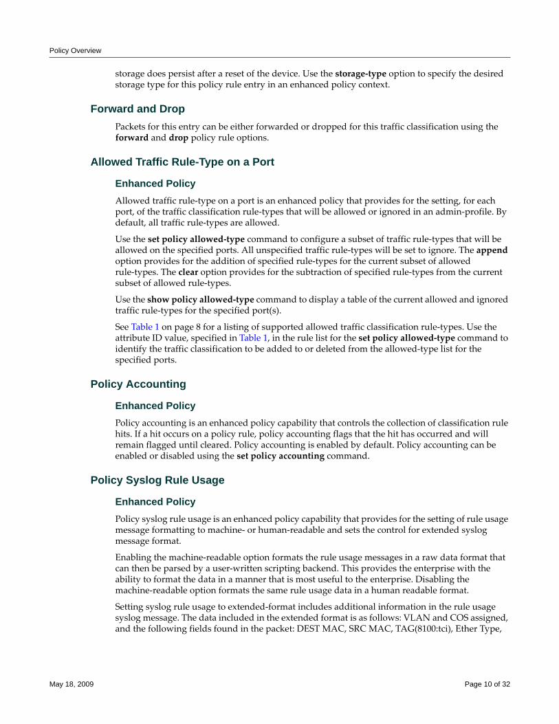
Policy Overview
storage does persist after a reset of the device. Use the storage‐type option to specify the desired storage type for this policy rule entry in an enhanced policy context.
Forward and DropPackets for this entry can be either forwarded or dropped for this traffic classification using the forward and drop policy rule options.
Allowed Traffic Rule-Type on a Port
Enhanced PolicyAllowed traffic rule‐type on a port is an enhanced policy that provides for the setting, for each port, of the traffic classification rule‐types that will be allowed or ignored in an admin‐profile. By default, all traffic rule‐types are allowed.
Use the set policy allowed‐type command to configure a subset of traffic rule‐types that will be allowed on the specified ports. All unspecified traffic rule‐types will be set to ignore. The append option provides for the addition of specified rule‐types for the current subset of allowed rule‐types. The clear option provides for the subtraction of specified rule‐types from the current subset of allowed rule‐types.
Use the show policy allowed‐type command to display a table of the current allowed and ignored traffic rule‐types for the specified port(s).
See Table 1 on page 8 for a listing of supported allowed traffic classification rule‐types. Use the attribute ID value, specified in Table 1, in the rule list for the set policy allowed‐type command to identify the traffic classification to be added to or deleted from the allowed‐type list for the specified ports.
Policy Accounting
Enhanced PolicyPolicy accounting is an enhanced policy capability that controls the collection of classification rule hits. If a hit occurs on a policy rule, policy accounting flags that the hit has occurred and will remain flagged until cleared. Policy accounting is enabled by default. Policy accounting can be enabled or disabled using the set policy accounting command.
Policy Syslog Rule Usage
Enhanced PolicyPolicy syslog rule usage is an enhanced policy capability that provides for the setting of rule usage message formatting to machine‐ or human‐readable and sets the control for extended syslog message format.
Enabling the machine‐readable option formats the rule usage messages in a raw data format that can then be parsed by a user‐written scripting backend. This provides the enterprise with the ability to format the data in a manner that is most useful to the enterprise. Disabling the machine‐readable option formats the same rule usage data in a human readable format.
Setting syslog rule usage to extended‐format includes additional information in the rule usage syslog message. The data included in the extended format is as follows: VLAN and COS assigned, and the following fields found in the packet: DEST MAC, SRC MAC, TAG(8100:tci), Ether Type,
May 18, 2009 Page 10 of 32
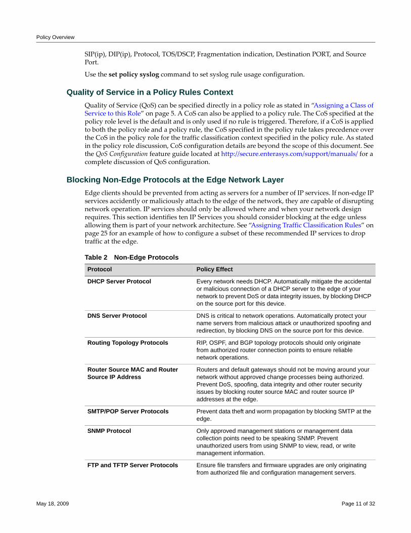
Policy Overview
SIP(ip), DIP(ip), Protocol, TOS/DSCP, Fragmentation indication, Destination PORT, and Source Port.
Use the set policy syslog command to set syslog rule usage configuration.
Quality of Service in a Policy Rules ContextQuality of Service (QoS) can be specified directly in a policy role as stated in “Assigning a Class of Service to this Role” on page 5. A CoS can also be applied to a policy rule. The CoS specified at the policy role level is the default and is only used if no rule is triggered. Therefore, if a CoS is applied to both the policy role and a policy rule, the CoS specified in the policy rule takes precedence over the CoS in the policy role for the traffic classification context specified in the policy rule. As stated in the policy role discussion, CoS configuration details are beyond the scope of this document. See the QoS Configuration feature guide located at http://secure.enterasys.com/support/manuals/ for a complete discussion of QoS configuration.
Blocking Non-Edge Protocols at the Edge Network LayerEdge clients should be prevented from acting as servers for a number of IP services. If non‐edge IP services accidently or maliciously attach to the edge of the network, they are capable of disrupting network operation. IP services should only be allowed where and when your network design requires. This section identifies ten IP Services you should consider blocking at the edge unless allowing them is part of your network architecture. See “Assigning Traffic Classification Rules” on page 25 for an example of how to configure a subset of these recommended IP services to drop traffic at the edge.
Table 2 Non-Edge ProtocolsProtocol Policy Effect
DHCP Server Protocol Every network needs DHCP. Automatically mitigate the accidental or malicious connection of a DHCP server to the edge of your network to prevent DoS or data integrity issues, by blocking DHCP on the source port for this device.
DNS Server Protocol DNS is critical to network operations. Automatically protect your name servers from malicious attack or unauthorized spoofing and redirection, by blocking DNS on the source port for this device.
Routing Topology Protocols RIP, OSPF, and BGP topology protocols should only originate from authorized router connection points to ensure reliable network operations.
Router Source MAC and Router Source IP Address
Routers and default gateways should not be moving around your network without approved change processes being authorized. Prevent DoS, spoofing, data integrity and other router security issues by blocking router source MAC and router source IP addresses at the edge.
SMTP/POP Server Protocols Prevent data theft and worm propagation by blocking SMTP at the edge.
SNMP Protocol Only approved management stations or management data collection points need to be speaking SNMP. Prevent unauthorized users from using SNMP to view, read, or write management information.
FTP and TFTP Server Protocols Ensure file transfers and firmware upgrades are only originating from authorized file and configuration management servers.
May 18, 2009 Page 11 of 32
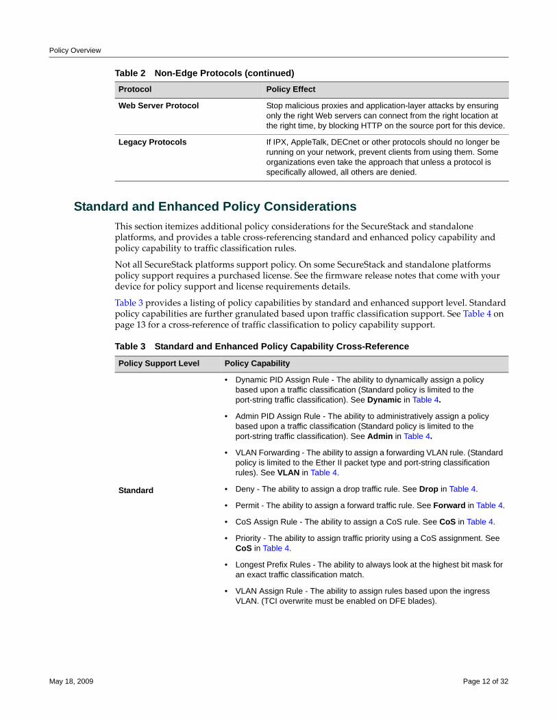
Policy Overview
Standard and Enhanced Policy ConsiderationsThis section itemizes additional policy considerations for the SecureStack and standalone platforms, and provides a table cross‐referencing standard and enhanced policy capability and policy capability to traffic classification rules.
Not all SecureStack platforms support policy. On some SecureStack and standalone platforms policy support requires a purchased license. See the firmware release notes that come with your device for policy support and license requirements details.
Table 3 provides a listing of policy capabilities by standard and enhanced support level. Standard policy capabilities are further granulated based upon traffic classification support. See Table 4 on page 13 for a cross‐reference of traffic classification to policy capability support.
Web Server Protocol Stop malicious proxies and application-layer attacks by ensuring only the right Web servers can connect from the right location at the right time, by blocking HTTP on the source port for this device.
Legacy Protocols If IPX, AppleTalk, DECnet or other protocols should no longer be running on your network, prevent clients from using them. Some organizations even take the approach that unless a protocol is specifically allowed, all others are denied.
Table 2 Non-Edge Protocols (continued)Protocol Policy Effect
Table 3 Standard and Enhanced Policy Capability Cross-Reference
Policy Support Level Policy Capability
Standard
• Dynamic PID Assign Rule - The ability to dynamically assign a policy based upon a traffic classification (Standard policy is limited to the port-string traffic classification). See Dynamic in Table 4.
• Admin PID Assign Rule - The ability to administratively assign a policy based upon a traffic classification (Standard policy is limited to the port-string traffic classification). See Admin in Table 4.
• VLAN Forwarding - The ability to assign a forwarding VLAN rule. (Standard policy is limited to the Ether II packet type and port-string classification rules). See VLAN in Table 4.
• Deny - The ability to assign a drop traffic rule. See Drop in Table 4.
• Permit - The ability to assign a forward traffic rule. See Forward in Table 4.
• CoS Assign Rule - The ability to assign a CoS rule. See CoS in Table 4.
• Priority - The ability to assign traffic priority using a CoS assignment. See CoS in Table 4.
• Longest Prefix Rules - The ability to always look at the highest bit mask for an exact traffic classification match.
• VLAN Assign Rule - The ability to assign rules based upon the ingress VLAN. (TCI overwrite must be enabled on DFE blades).
May 18, 2009 Page 12 of 32
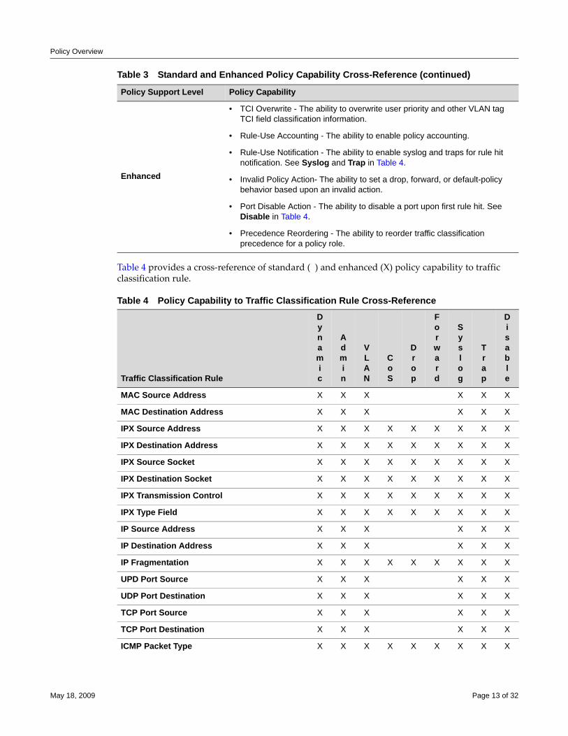
Policy Overview
Table 4 provides a cross‐reference of standard ( ) and enhanced (X) policy capability to traffic classification rule.
Enhanced
• TCI Overwrite - The ability to overwrite user priority and other VLAN tag TCI field classification information.
• Rule-Use Accounting - The ability to enable policy accounting.
• Rule-Use Notification - The ability to enable syslog and traps for rule hit notification. See Syslog and Trap in Table 4.
• Invalid Policy Action- The ability to set a drop, forward, or default-policy behavior based upon an invalid action.
• Port Disable Action - The ability to disable a port upon first rule hit. See Disable in Table 4.
• Precedence Reordering - The ability to reorder traffic classification precedence for a policy role.
Table 4 Policy Capability to Traffic Classification Rule Cross-Reference
Traffic Classification Rule
Dynamic
Admin
VLAN
CoS
Drop
Forward
Syslog
Trap
Disable
MAC Source Address X X X X X X
MAC Destination Address X X X X X X
IPX Source Address X X X X X X X X X
IPX Destination Address X X X X X X X X X
IPX Source Socket X X X X X X X X X
IPX Destination Socket X X X X X X X X X
IPX Transmission Control X X X X X X X X X
IPX Type Field X X X X X X X X X
IP Source Address X X X X X X
IP Destination Address X X X X X X
IP Fragmentation X X X X X X X X X
UPD Port Source X X X X X X
UDP Port Destination X X X X X X
TCP Port Source X X X X X X
TCP Port Destination X X X X X X
ICMP Packet Type X X X X X X X X X
Table 3 Standard and Enhanced Policy Capability Cross-Reference (continued)
Policy Support Level Policy Capability
May 18, 2009 Page 13 of 32
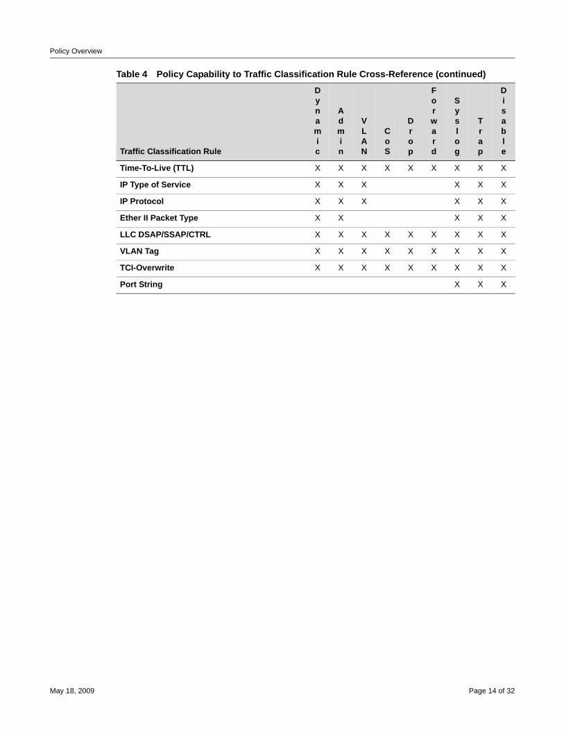
Policy Overview
Time-To-Live (TTL) X X X X X X X X X
IP Type of Service X X X X X X
IP Protocol X X X X X X
Ether II Packet Type X X X X X
LLC DSAP/SSAP/CTRL X X X X X X X X X
VLAN Tag X X X X X X X X X
TCI-Overwrite X X X X X X X X X
Port String X X X
Table 4 Policy Capability to Traffic Classification Rule Cross-Reference (continued)
Traffic Classification Rule
Dynamic
Admin
VLAN
CoS
Drop
Forward
Syslog
Trap
Disable
May 18, 2009 Page 14 of 32
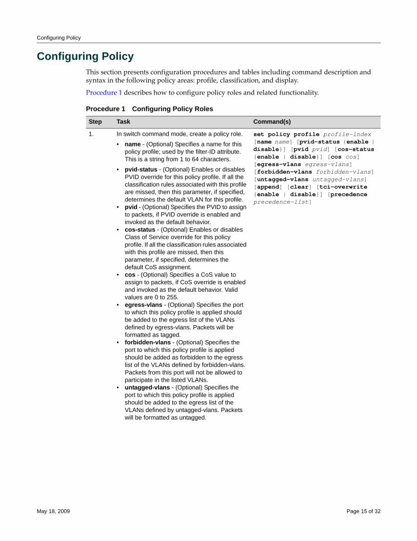
Configuring Policy
Configuring PolicyThis section presents configuration procedures and tables including command description and syntax in the following policy areas: profile, classification, and display.
Procedure 1 describes how to configure policy roles and related functionality.
Procedure 1 Configuring Policy Roles
Step Task Command(s)
1. In switch command mode, create a policy role.
• name - (Optional) Specifies a name for this policy profile; used by the filter-ID attribute. This is a string from 1 to 64 characters.
• pvid-status - (Optional) Enables or disables PVID override for this policy profile. If all the classification rules associated with this profile are missed, then this parameter, if specified, determines the default VLAN for this profile.
• pvid - (Optional) Specifies the PVID to assign to packets, if PVID override is enabled and invoked as the default behavior.
• cos-status - (Optional) Enables or disables Class of Service override for this policy profile. If all the classification rules associated with this profile are missed, then this parameter, if specified, determines the default CoS assignment.
• cos - (Optional) Specifies a CoS value to assign to packets, if CoS override is enabled and invoked as the default behavior. Valid values are 0 to 255.
• egress-vlans - (Optional) Specifies the port to which this policy profile is applied should be added to the egress list of the VLANs defined by egress-vlans. Packets will be formatted as tagged.
• forbidden-vlans - (Optional) Specifies the port to which this policy profile is applied should be added as forbidden to the egress list of the VLANs defined by forbidden-vlans. Packets from this port will not be allowed to participate in the listed VLANs.
• untagged-vlans - (Optional) Specifies the port to which this policy profile is applied should be added to the egress list of the VLANs defined by untagged-vlans. Packets will be formatted as untagged.
set policy profile profile-index [name name] [pvid-status {enable | disable}] [pvid pvid] [cos-status {enable | disable}] [cos cos] [egress-vlans egress-vlans] [forbidden-vlans forbidden-vlans] [untagged-vlans untagged-vlans] [append] [clear] [tci-overwrite {enable | disable}] [precedence precedence-list]
May 18, 2009 Page 15 of 32
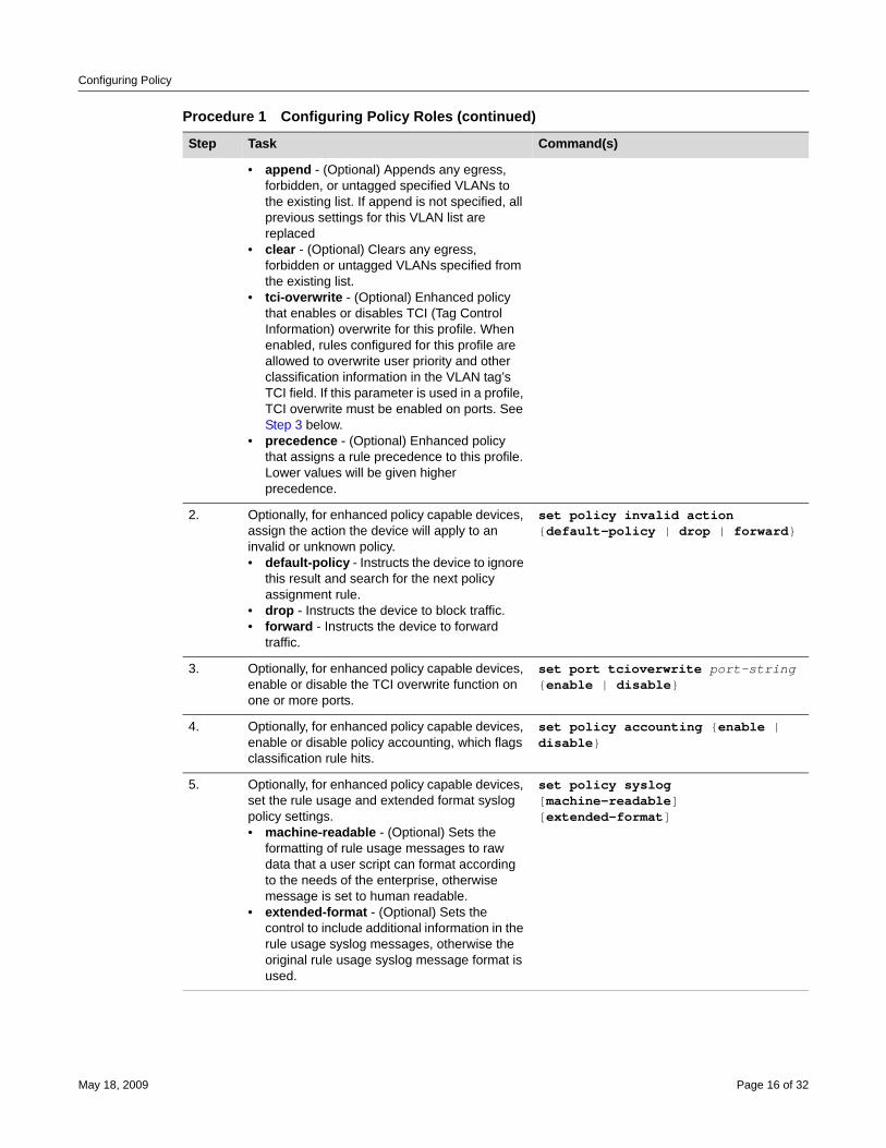
Configuring Policy
• append - (Optional) Appends any egress, forbidden, or untagged specified VLANs to the existing list. If append is not specified, all previous settings for this VLAN list are replaced
• clear - (Optional) Clears any egress, forbidden or untagged VLANs specified from the existing list.
• tci-overwrite - (Optional) Enhanced policy that enables or disables TCI (Tag Control Information) overwrite for this profile. When enabled, rules configured for this profile are allowed to overwrite user priority and other classification information in the VLAN tag’s TCI field. If this parameter is used in a profile, TCI overwrite must be enabled on ports. See Step 3 below.
• precedence - (Optional) Enhanced policy that assigns a rule precedence to this profile. Lower values will be given higher precedence.
2. Optionally, for enhanced policy capable devices, assign the action the device will apply to an invalid or unknown policy.• default-policy - Instructs the device to ignore
this result and search for the next policy assignment rule.
• drop - Instructs the device to block traffic.• forward - Instructs the device to forward
traffic.
set policy invalid action {default-policy | drop | forward}
3. Optionally, for enhanced policy capable devices, enable or disable the TCI overwrite function on one or more ports.
set port tcioverwrite port-string {enable | disable}
4. Optionally, for enhanced policy capable devices, enable or disable policy accounting, which flags classification rule hits.
set policy accounting {enable | disable}
5. Optionally, for enhanced policy capable devices, set the rule usage and extended format syslog policy settings.• machine-readable - (Optional) Sets the
formatting of rule usage messages to raw data that a user script can format according to the needs of the enterprise, otherwise message is set to human readable.
• extended-format - (Optional) Sets the control to include additional information in the rule usage syslog messages, otherwise the original rule usage syslog message format is used.
set policy syslog [machine-readable] [extended-format]
Procedure 1 Configuring Policy Roles (continued)
Step Task Command(s)
May 18, 2009 Page 16 of 32
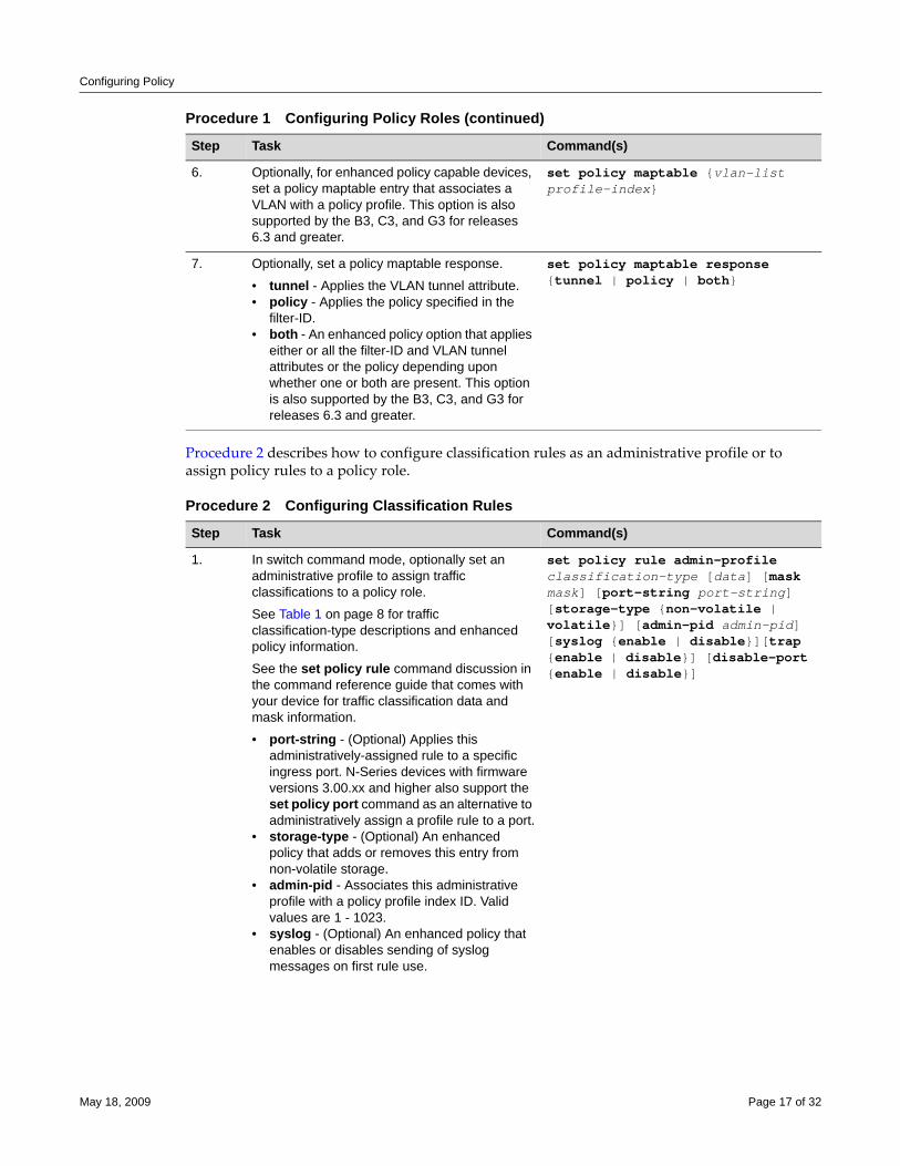
Configuring Policy
Procedure 2 describes how to configure classification rules as an administrative profile or to assign policy rules to a policy role.
6. Optionally, for enhanced policy capable devices, set a policy maptable entry that associates a VLAN with a policy profile. This option is also supported by the B3, C3, and G3 for releases 6.3 and greater.
set policy maptable {vlan-list profile-index}
7. Optionally, set a policy maptable response.
• tunnel - Applies the VLAN tunnel attribute.• policy - Applies the policy specified in the
filter-ID.• both - An enhanced policy option that applies
either or all the filter-ID and VLAN tunnel attributes or the policy depending upon whether one or both are present. This option is also supported by the B3, C3, and G3 for releases 6.3 and greater.
set policy maptable response {tunnel | policy | both}
Procedure 2 Configuring Classification Rules
Step Task Command(s)
1. In switch command mode, optionally set an administrative profile to assign traffic classifications to a policy role.
See Table 1 on page 8 for traffic classification-type descriptions and enhanced policy information.
See the set policy rule command discussion in the command reference guide that comes with your device for traffic classification data and mask information.
• port-string - (Optional) Applies this administratively-assigned rule to a specific ingress port. N-Series devices with firmware versions 3.00.xx and higher also support the set policy port command as an alternative to administratively assign a profile rule to a port.
• storage-type - (Optional) An enhanced policy that adds or removes this entry from non-volatile storage.
• admin-pid - Associates this administrative profile with a policy profile index ID. Valid values are 1 - 1023.
• syslog - (Optional) An enhanced policy that enables or disables sending of syslog messages on first rule use.
set policy rule admin-profile classification-type [data] [mask mask] [port-string port-string] [storage-type {non-volatile | volatile}] [admin-pid admin-pid] [syslog {enable | disable}][trap {enable | disable}] [disable-port {enable | disable}]
Procedure 1 Configuring Policy Roles (continued)
Step Task Command(s)
May 18, 2009 Page 17 of 32
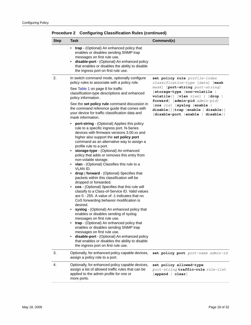
Configuring Policy
• trap - (Optional) An enhanced policy that enables or disables sending SNMP trap messages on first rule use.
• disable-port - (Optional) An enhanced policy that enables or disables the ability to disable the ingress port on first rule use.
2. In switch command mode, optionally configure policy rules to associate with a policy role.
See Table 1 on page 8 for traffic classification-type descriptions and enhanced policy information.
See the set policy rule command discussion in the command reference guide that comes with your device for traffic classification data and mask information.
• port-string - (Optional) Applies this policy rule to a specific ingress port. N-Series devices with firmware versions 3.00.xx and higher also support the set policy port command as an alternative way to assign a profile rule to a port.
• storage-type - (Optional) An enhanced policy that adds or removes this entry from non-volatile storage.
• vlan - (Optional) Classifies this rule to a VLAN ID.
• drop | forward - (Optional) Specifies that packets within this classification will be dropped or forwarded.
• cos - (Optional) Specifies that this rule will classify to a Class-of-Service ID. Valid values are 0 - 255. A value of -1 indicates that no CoS forwarding behavior modification is desired.
• syslog - (Optional) An enhanced policy that enables or disables sending of syslog messages on first rule use.
• trap - (Optional) An enhanced policy that enables or disables sending SNMP trap messages on first rule use.
• disable-port - (Optional) An enhanced policy that enables or disables the ability to disable the ingress port on first rule use.
set policy rule profile-index classification-type [data] [mask mask] [port-string port-string] [storage-type {non-volatile | volatile}] [vlan vlan] | [drop | forward] [admin-pid admin-pid] [cos cos] [syslog {enable | disable}][trap {enable | disable}] [disable-port {enable | disable}]
3. Optionally, for enhanced policy capable devices, assign a policy role to a port.
set policy port port-name admin-id
4. Optionally, for enhanced policy capable devices, assign a list of allowed traffic rules that can be applied to the admin profile for one ormore ports.
set policy allowed-type port-string traffic-rule rule-list [append | clear]
Procedure 2 Configuring Classification Rules (continued)
Step Task Command(s)
May 18, 2009 Page 18 of 32
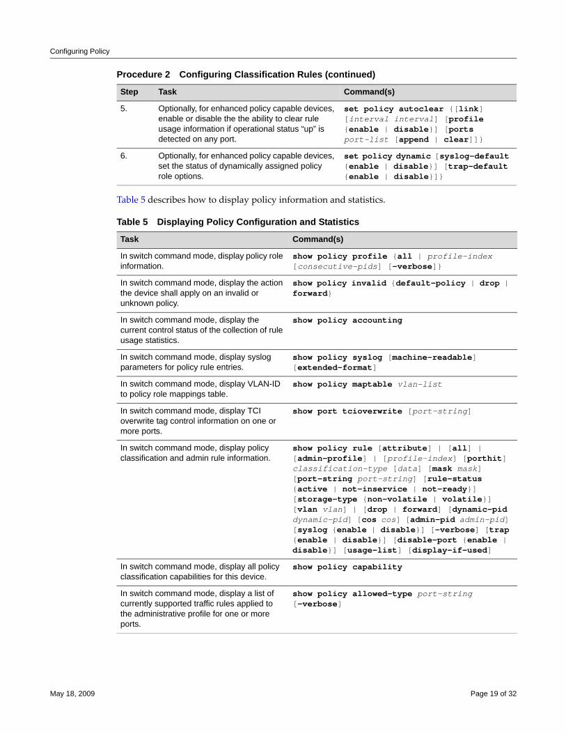
Configuring Policy
Table 5 describes how to display policy information and statistics.
5. Optionally, for enhanced policy capable devices, enable or disable the the ability to clear rule usage information if operational status “up” is detected on any port.
set policy autoclear {[link] [interval interval] [profile {enable | disable}] [ports port-list [append | clear]]}
6. Optionally, for enhanced policy capable devices, set the status of dynamically assigned policy role options.
set policy dynamic [syslog-default {enable | disable}] [trap-default {enable | disable}]}
Table 5 Displaying Policy Configuration and Statistics
Task Command(s)
In switch command mode, display policy role information.
show policy profile {all | profile-index [consecutive-pids] [-verbose]}
In switch command mode, display the action the device shall apply on an invalid or unknown policy.
show policy invalid {default-policy | drop | forward}
In switch command mode, display the current control status of the collection of rule usage statistics.
show policy accounting
In switch command mode, display syslog parameters for policy rule entries.
show policy syslog [machine-readable] [extended-format]
In switch command mode, display VLAN-ID to policy role mappings table.
show policy maptable vlan-list
In switch command mode, display TCI overwrite tag control information on one or more ports.
show port tcioverwrite [port-string]
In switch command mode, display policy classification and admin rule information.
show policy rule [attribute] | [all] | [admin-profile] | [profile-index] [porthit] classification-type [data] [mask mask] [port-string port-string] [rule-status {active | not-inservice | not-ready}] [storage-type {non-volatile | volatile}] [vlan vlan] | [drop | forward] [dynamic-pid dynamic-pid] [cos cos] [admin-pid admin-pid] [syslog {enable | disable}] [-verbose] [trap {enable | disable}] [disable-port {enable | disable}] [usage-list] [display-if-used]
In switch command mode, display all policy classification capabilities for this device.
show policy capability
In switch command mode, display a list of currently supported traffic rules applied to the administrative profile for one or more ports.
show policy allowed-type port-string [-verbose]
Procedure 2 Configuring Classification Rules (continued)
Step Task Command(s)
May 18, 2009 Page 19 of 32
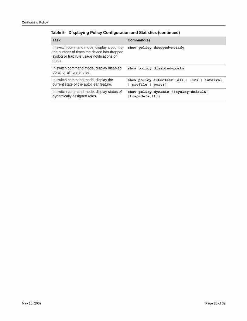
Configuring Policy
In switch command mode, display a count of the number of times the device has dropped syslog or trap rule usage notifications on ports.
show policy dropped-notify
In switch command mode, display disabled ports for all rule entries.
show policy disabled-ports
In switch command mode, display the current state of the autoclear feature.
show policy autoclear {all | link | interval | profile | ports}
In switch command mode, display status of dynamically assigned roles.
show policy dynamic {[syslog-default] [trap-default]}
Table 5 Displaying Policy Configuration and Statistics (continued)
Task Command(s)
May 18, 2009 Page 20 of 32
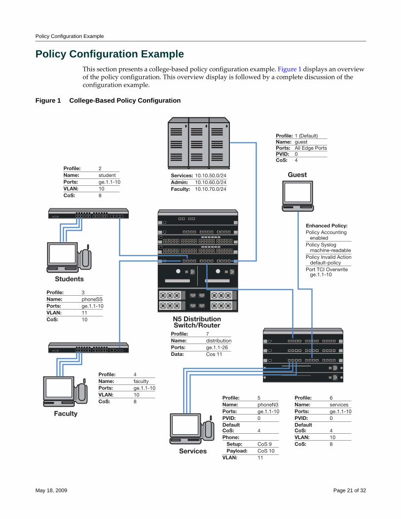
Policy Configuration Example
Policy Configuration ExampleThis section presents a college‐based policy configuration example. Figure 1 displays an overview of the policy configuration. This overview display is followed by a complete discussion of the configuration example.
Figure 1 College-Based Policy Configuration
Students
Services:Admin:Faculty:
Profile:Name:Ports:VLAN:CoS:
2studentge.1.1-10108
Profile:Name:Ports:VLAN:CoS:
4facultyge.1.1-10108
Profile:Name:Ports:Data:
7distributionge.1.1-26Cos 11
Profile:Name:Ports:PVID:DefaultCoS:Phone: Setup: Payload:VLAN:
5phoneN3ge.1.1-100
4
CoS 9CoS 1011
Profile:Name:Ports:PVID:DefaultCoS:VLAN:CoS:
6servicesge.1.1-100
4108
Enhanced Policy:Policy Accounting enabledPolicy Syslog machine-readablePolicy Invalid Action default-policyPort TCI Overwrite ge.1.1-10
Faculty
Services
10.10.50.0/2410.10.60.0/2410.10.70.0/24
Profile:Name:Ports:PVID:CoS:
1 (Default)guestAll Edge Ports04
Guest
Profile:Name:Ports:VLAN:CoS:
3phoneSSge.1.1-101110 N5 Distribution
Switch/Router
May 18, 2009 Page 21 of 32
Policy Configuration Example
RolesThe example defines the following roles:
• guest ‐ Used as the default policy for all unauthenticated ports. Connects a PC to the network providing internet only access to the network. Provides guest access to a limited number of N3 ports to be used specifically for internet only access. Policy is applied using the port level default configuration, or by authentication, in the case of the N3 port internet only access PCs.
• student ‐ Connects a dorm room PC to the network through a “Student” SecureStack C3 port. A configured CoS rate limits the PC. Configured rules deny access to administrative and faculty servers. The PC authenticates using RADIUS. Hybrid authentication is enabled. The student policy role is applied using the filter‐ID attribute. The base VLAN is applied using the tunnel attributes returned in the RADIUS response message. If all rules are missed, the settings configured in the student policy profile are applied.
• phoneSS ‐ Connects a dorm room or faculty office VoIP phone to the network using a SecureStack port. A configured CoS rate limits the phone and applies a high priority. The phone authenticates using RADIUS. Hybrid authentication is enabled. Policy is applied using the filter‐ID returned in the RADIUS response message. The base VLAN is applied using the tunnel attributes returned in the RADIUS response message. If all rules are missed, the settings configured in the phoneSS policy profile are applied.
• faculty ‐ Connects a faculty office PC to the network through a “Faculty” SecureStack C3 port. A configured CoS rate limits the PC. A configured rule denies access to the administrative servers. The PC authenticates using RADIUS. Hybrid authentication is enabled. The faculty policy role is applied using the filter‐ID attribute. The base VLAN is applied using the tunnel attributes returned in the RADIUS response message for the authenticating user. If all rules are missed, the settings configured in the faculty policy profile are applied.
• phoneN3 ‐ Connects a services VoIP phone to the network using an N3 port. A configured CoS rate limits the phone for both setup and payload, and applies a high priority. The phone authenticates using RADIUS. Tunnel authentication is enabled. The base VLAN is applied using the tunnel attributes returned in the RADIUS response message. Policy is applied using a maptable configuration. If all rules are missed, the settings configured in the phoneN3 policy profile are applied.
• services ‐ Connects a services PC to the network through an N3 port. A configured CoS rate limits the PC. Services are denied access to both the student and faculty servers. The PC authenticates using RADIUS. The base VLAN is applied using the tunnel attributes returned in the RADIUS response message for the authenticating user. The services policy role is applied using a policy maptable setting. The policy accounting, syslog, invalid action and TCI overwrite enhanced policies are enabled for this role. If all rules are missed, the settings configured in the services policy profile are applied.
• distribution ‐ The Distribution policy role is applied at the distribution layer providing rate limiting.
Policy DomainsIt is useful to break up policy implementation into logical domains for ease of understanding and configuration. For this example, it is useful to consider four domains: basic edge, standard edge on the SecureStacks, premium edge on the N3, and premium distribution.
May 18, 2009 Page 22 of 32
Policy Configuration Example
Basic EdgeProtocols not appropriate to the edge should be blocked. For this example we will block DHCP, DNS, SNMP, SSH, Telnet and FTP at the edge on the data VLAN. We will forward destination port DHCP and DNS and source port for IP address request to facilitate auto configuration and IP address assignment. See Blocking Non‐Edge Protocols at the Edge Network Layer on page 11 for a listing of protocols you should consider blocking at the edge.
Standard EdgePlatforms supporting standard policy will be rate‐limited using a configured CoS that will be applied to the student and faculty, and phoneSS policy roles. Though listed as an enhanced policy feature, the SecureStack C3 supports the hybrid authentication enhanced policy capability. Hybrid authentication will be enabled.
Premium EdgePlatforms supporting enhanced policy will be rate‐limited using a configured CoS that is applied to the services and phoneN3 policy role. The premium edge will be enabled for the following enhanced policy capabilities:
• Policy Accounting
• Syslog rule usage enabled and set to machine‐readable
• Invalid policy action set to drop
• TCI overwrite enabled
Premium DistributionThe distribution layer switch router will be rate‐limited using a configured CoS. Premium distribution will be enabled for the following enhanced policy capabilities:
• Policy Accounting
• Syslog Rule Usage enabled and set to machine‐readable
• Invalid policy action set to drop
• TCI overwrite enabled
Platform ConfigurationThis section will provide the CLI based policy configuration on the following platforms:
• Student SecureStack C3
• Faculty SecureStack C3
• Services N3
• Distribution Switch
In CLI mode, configuration takes place on each platform. When using the NetSight Policy Manager, configuration takes place at a central location and is pushed out to the appropriate network devices.
May 18, 2009 Page 23 of 32
Policy Configuration Example
For this configuration example, CoS related configuration will be specified as a final CoS. For details on configuring CoS, see the QoS Configuration feature guide located at http://secure.enterasys.com/support/manuals/.
Configuring Guest Policy on Edge PlatformsAll edge ports will be set with a default guest policy using the set policy port command. This guest policy provides for an internet only access to the network. Users on all ports will attempt to authenticate. If the authentication succeeds, the policy returned by authentication or, in the case of the N3 configuration, the maptable setting, overrides the default port policy setting. If authentication fails, the guest policy is used. On the N3, five ports are used by PCs at locations throughout the campus, such as the library, to provide access to the internet. The PCs attached to these five ports will authenticate with the guest policy role. Public facing services would also be configured for guest status in a school or enterprise scenario. Public facing services are not part of this example.
Configuring the Policy RoleThe guest role is configured with:
• A profile‐index value of 1
• A name of guest
• A PVID set to 0
• A CoS set to 4
Create the guest policy profile on all platforms:
Enterasys(rw)->set policy profile 1 name guest pvid-status enable pvid 0 cos-status enable cos 4
Assigning Traffic Classification RulesFor cases where discovery must take place to assign an IP address, DNS and DHCP traffic must be allowed. Forwarding of traffic is allowed on UDP source port 68 (IP address request) and UDP destination ports 53 (DNS) and 67 (DHCP).
Enterasys(rw)->set policy rule 1 udpsourceport 68 mask 16 forwardEnterasys(rw)->set policy rule 1 udpdestportIP 53 mask 16 forwardEnterasys(rw)->set policy rule 1 udpdestportIP 67 mask 16 forward
Guest policy allows internet traffic. TCP destination Ports 80, 8080, and 443 will be allowed traffic forwarding.
Enterasys(rw)->set policy rule 1 tcpdestportIP 80 mask 16 forwardEnterasys(rw)->set policy rule 1 tcpdestportIP 443 mask 16 forwardEnterasys(rw)->set policy rule 1 tcpdestport 8080 mask 16 forward
Note: CLI command prompts used in this configuration example have the following meaning:
• Enterasys(rw)-> - Input on all platforms used in this example.
• C3(rw)-> - Input on all SecureStack C3 switches.
• StudentC3-> - Input on the student SecureStack C3.
• FacultyC3-> - Input on the faculty SecureStack C3.
• ServicesN3(rw)-> - Input on the services N-Series N3.
• DistributionN5(rw)-> - Input on the distribution N-Series N5.
May 18, 2009 Page 24 of 32
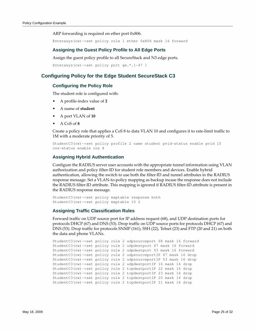
Policy Configuration Example
ARP forwarding is required on ether port 0x806.
Enterasys(rw)->set policy rule 1 ether 0x806 mask 16 forward
Assigning the Guest Policy Profile to All Edge PortsAssign the guest policy profile to all SecureStack and N3 edge ports.
Enterasys(rw)->set policy port ge.*.1-47 1
Configuring Policy for the Edge Student SecureStack C3
Configuring the Policy RoleThe student role is configured with:
• A profile‐index value of 2
• A name of student
• A port VLAN of 10
• A CoS of 8
Create a policy role that applies a CoS 8 to data VLAN 10 and configures it to rate‐limit traffic to 1M with a moderate priority of 5.
StudentC3(rw)->set policy profile 2 name student pvid-status enable pvid 10 cos-status enable cos 8
Assigning Hybrid AuthenticationConfigure the RADIUS server user accounts with the appropriate tunnel information using VLAN authorization and policy filter‐ID for student role members and devices. Enable hybrid authentication, allowing the switch to use both the filter‐ID and tunnel attributes in the RADIUS response message. Set a VLAN‐to‐policy mapping as backup incase the response does not include the RADIUS filter‐ID attribute. This mapping is ignored if RADIUS filter‐ID attribute is present in the RADIUS response message.
StudentC3(rw)->set policy maptable response bothStudentC3(rw)->set policy maptable 10 2
Assigning Traffic Classification RulesForward traffic on UDP source port for IP address request (68), and UDP destination ports for protocols DHCP (67) and DNS (53). Drop traffic on UDP source ports for protocols DHCP (67) and DNS (53). Drop traffic for protocols SNMP (161), SSH (22), Telnet (23) and FTP (20 and 21) on both the data and phone VLANs.
StudentC3(rw)->set policy rule 2 udpsourceport 68 mask 16 forwardStudentC3(rw)->set policy rule 2 udpdestport 67 mask 16 forwardStudentC3(rw)->set policy rule 2 udpdestport 53 mask 16 forwardStudentC3(rw)->set policy rule 2 udpsourceportIP 67 mask 16 dropStudentC3(rw)->set policy rule 2 udpsourceportIP 53 mask 16 dropStudentC3(rw)->set policy rule 2 udpdestportIP 16 mask 16 dropStudentC3(rw)->set policy rule 2 tcpdestportIP 22 mask 16 dropStudentC3(rw)->set policy rule 2 tcpdestportIP 23 mask 16 dropStudentC3(rw)->set policy rule 2 tcpdestportIP 20 mask 16 dropStudentC3(rw)->set policy rule 2 tcpdestportIP 21 mask 16 drop
May 18, 2009 Page 25 of 32
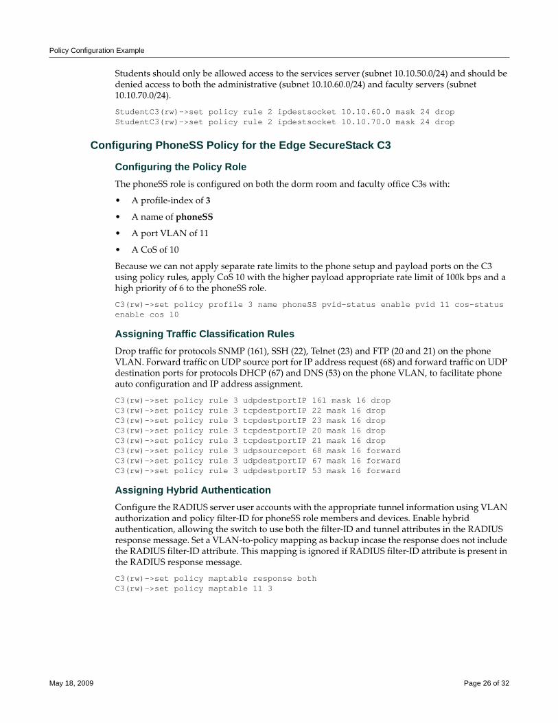
Policy Configuration Example
Students should only be allowed access to the services server (subnet 10.10.50.0/24) and should be denied access to both the administrative (subnet 10.10.60.0/24) and faculty servers (subnet 10.10.70.0/24).
StudentC3(rw)->set policy rule 2 ipdestsocket 10.10.60.0 mask 24 dropStudentC3(rw)->set policy rule 2 ipdestsocket 10.10.70.0 mask 24 drop
Configuring PhoneSS Policy for the Edge SecureStack C3
Configuring the Policy RoleThe phoneSS role is configured on both the dorm room and faculty office C3s with:
• A profile‐index of 3
• A name of phoneSS
• A port VLAN of 11
• A CoS of 10
Because we can not apply separate rate limits to the phone setup and payload ports on the C3 using policy rules, apply CoS 10 with the higher payload appropriate rate limit of 100k bps and a high priority of 6 to the phoneSS role.
C3(rw)->set policy profile 3 name phoneSS pvid-status enable pvid 11 cos-status enable cos 10
Assigning Traffic Classification RulesDrop traffic for protocols SNMP (161), SSH (22), Telnet (23) and FTP (20 and 21) on the phone VLAN. Forward traffic on UDP source port for IP address request (68) and forward traffic on UDP destination ports for protocols DHCP (67) and DNS (53) on the phone VLAN, to facilitate phone auto configuration and IP address assignment.
C3(rw)->set policy rule 3 udpdestportIP 161 mask 16 dropC3(rw)->set policy rule 3 tcpdestportIP 22 mask 16 dropC3(rw)->set policy rule 3 tcpdestportIP 23 mask 16 dropC3(rw)->set policy rule 3 tcpdestportIP 20 mask 16 dropC3(rw)->set policy rule 3 tcpdestportIP 21 mask 16 dropC3(rw)->set policy rule 3 udpsourceport 68 mask 16 forwardC3(rw)->set policy rule 3 udpdestportIP 67 mask 16 forwardC3(rw)->set policy rule 3 udpdestportIP 53 mask 16 forward
Assigning Hybrid AuthenticationConfigure the RADIUS server user accounts with the appropriate tunnel information using VLAN authorization and policy filter‐ID for phoneSS role members and devices. Enable hybrid authentication, allowing the switch to use both the filter‐ID and tunnel attributes in the RADIUS response message. Set a VLAN‐to‐policy mapping as backup incase the response does not include the RADIUS filter‐ID attribute. This mapping is ignored if RADIUS filter‐ID attribute is present in the RADIUS response message.
C3(rw)->set policy maptable response bothC3(rw)->set policy maptable 11 3
May 18, 2009 Page 26 of 32
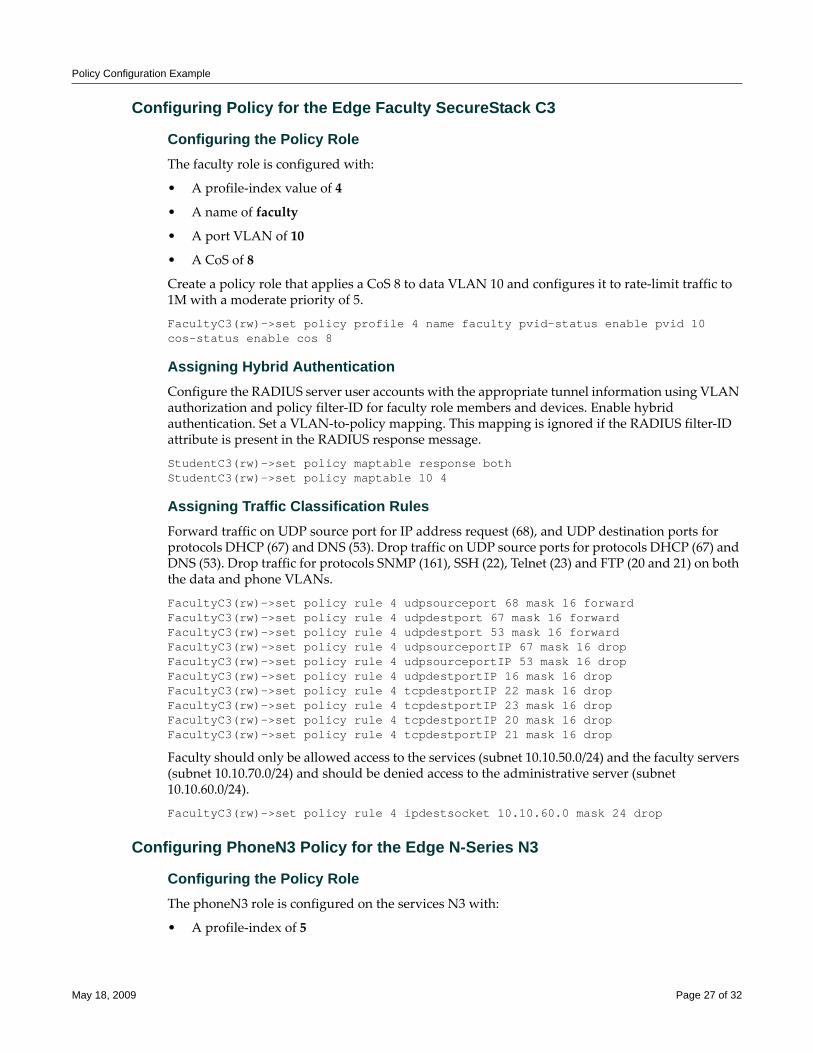
Policy Configuration Example
Configuring Policy for the Edge Faculty SecureStack C3
Configuring the Policy RoleThe faculty role is configured with:
• A profile‐index value of 4
• A name of faculty
• A port VLAN of 10
• A CoS of 8
Create a policy role that applies a CoS 8 to data VLAN 10 and configures it to rate‐limit traffic to 1M with a moderate priority of 5.
FacultyC3(rw)->set policy profile 4 name faculty pvid-status enable pvid 10 cos-status enable cos 8
Assigning Hybrid AuthenticationConfigure the RADIUS server user accounts with the appropriate tunnel information using VLAN authorization and policy filter‐ID for faculty role members and devices. Enable hybrid authentication. Set a VLAN‐to‐policy mapping. This mapping is ignored if the RADIUS filter‐ID attribute is present in the RADIUS response message.
StudentC3(rw)->set policy maptable response bothStudentC3(rw)->set policy maptable 10 4
Assigning Traffic Classification RulesForward traffic on UDP source port for IP address request (68), and UDP destination ports for protocols DHCP (67) and DNS (53). Drop traffic on UDP source ports for protocols DHCP (67) and DNS (53). Drop traffic for protocols SNMP (161), SSH (22), Telnet (23) and FTP (20 and 21) on both the data and phone VLANs.
FacultyC3(rw)->set policy rule 4 udpsourceport 68 mask 16 forwardFacultyC3(rw)->set policy rule 4 udpdestport 67 mask 16 forwardFacultyC3(rw)->set policy rule 4 udpdestport 53 mask 16 forwardFacultyC3(rw)->set policy rule 4 udpsourceportIP 67 mask 16 dropFacultyC3(rw)->set policy rule 4 udpsourceportIP 53 mask 16 dropFacultyC3(rw)->set policy rule 4 udpdestportIP 16 mask 16 dropFacultyC3(rw)->set policy rule 4 tcpdestportIP 22 mask 16 dropFacultyC3(rw)->set policy rule 4 tcpdestportIP 23 mask 16 dropFacultyC3(rw)->set policy rule 4 tcpdestportIP 20 mask 16 dropFacultyC3(rw)->set policy rule 4 tcpdestportIP 21 mask 16 drop
Faculty should only be allowed access to the services (subnet 10.10.50.0/24) and the faculty servers (subnet 10.10.70.0/24) and should be denied access to the administrative server (subnet 10.10.60.0/24).
FacultyC3(rw)->set policy rule 4 ipdestsocket 10.10.60.0 mask 24 drop
Configuring PhoneN3 Policy for the Edge N-Series N3
Configuring the Policy RoleThe phoneN3 role is configured on the services N3 with:
• A profile‐index of 5
May 18, 2009 Page 27 of 32
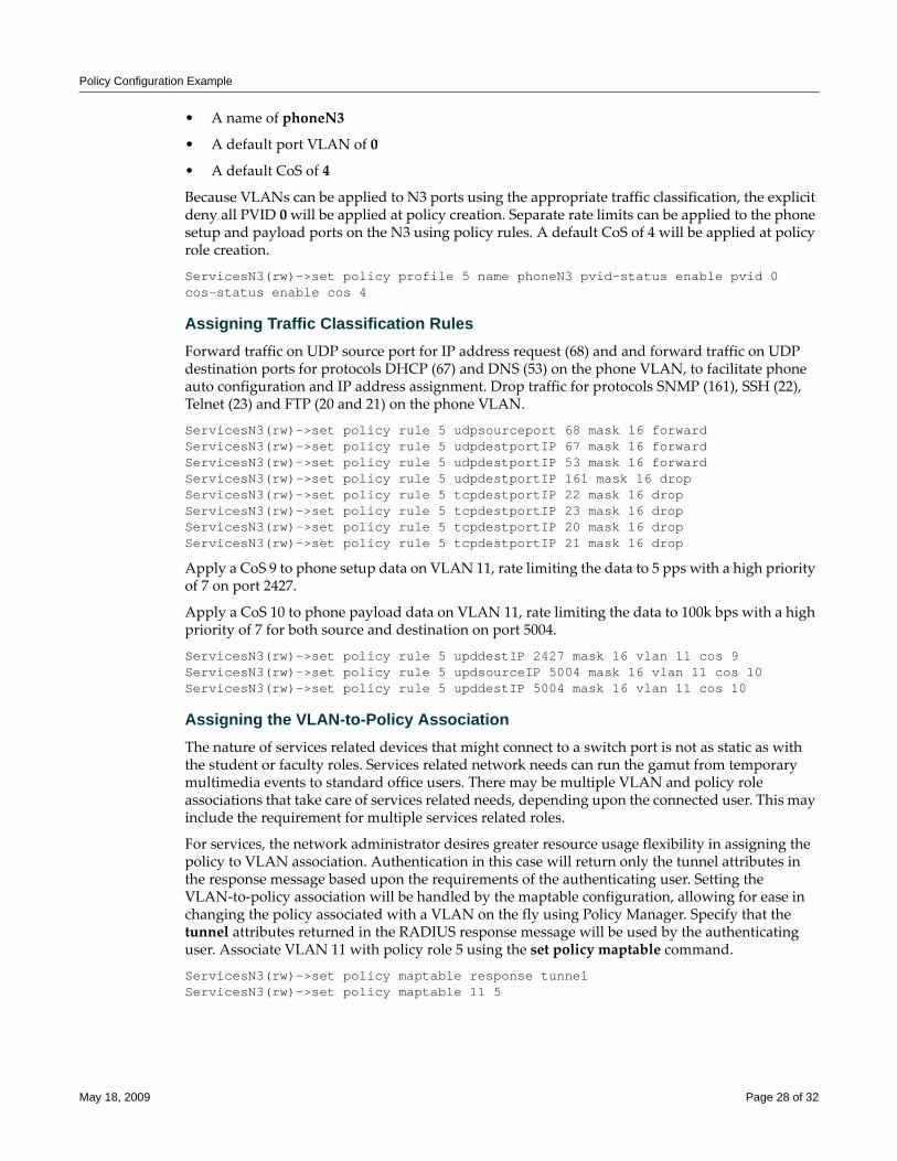
Policy Configuration Example
• A name of phoneN3
• A default port VLAN of 0
• A default CoS of 4
Because VLANs can be applied to N3 ports using the appropriate traffic classification, the explicit deny all PVID 0 will be applied at policy creation. Separate rate limits can be applied to the phone setup and payload ports on the N3 using policy rules. A default CoS of 4 will be applied at policy role creation.
ServicesN3(rw)->set policy profile 5 name phoneN3 pvid-status enable pvid 0 cos-status enable cos 4
Assigning Traffic Classification RulesForward traffic on UDP source port for IP address request (68) and and forward traffic on UDP destination ports for protocols DHCP (67) and DNS (53) on the phone VLAN, to facilitate phone auto configuration and IP address assignment. Drop traffic for protocols SNMP (161), SSH (22), Telnet (23) and FTP (20 and 21) on the phone VLAN.
ServicesN3(rw)->set policy rule 5 udpsourceport 68 mask 16 forwardServicesN3(rw)->set policy rule 5 udpdestportIP 67 mask 16 forwardServicesN3(rw)->set policy rule 5 udpdestportIP 53 mask 16 forwardServicesN3(rw)->set policy rule 5 udpdestportIP 161 mask 16 dropServicesN3(rw)->set policy rule 5 tcpdestportIP 22 mask 16 dropServicesN3(rw)->set policy rule 5 tcpdestportIP 23 mask 16 dropServicesN3(rw)->set policy rule 5 tcpdestportIP 20 mask 16 dropServicesN3(rw)->set policy rule 5 tcpdestportIP 21 mask 16 drop
Apply a CoS 9 to phone setup data on VLAN 11, rate limiting the data to 5 pps with a high priority of 7 on port 2427.
Apply a CoS 10 to phone payload data on VLAN 11, rate limiting the data to 100k bps with a high priority of 7 for both source and destination on port 5004.
ServicesN3(rw)->set policy rule 5 upddestIP 2427 mask 16 vlan 11 cos 9ServicesN3(rw)->set policy rule 5 updsourceIP 5004 mask 16 vlan 11 cos 10ServicesN3(rw)->set policy rule 5 upddestIP 5004 mask 16 vlan 11 cos 10
Assigning the VLAN-to-Policy AssociationThe nature of services related devices that might connect to a switch port is not as static as with the student or faculty roles. Services related network needs can run the gamut from temporary multimedia events to standard office users. There may be multiple VLAN and policy role associations that take care of services related needs, depending upon the connected user. This may include the requirement for multiple services related roles.
For services, the network administrator desires greater resource usage flexibility in assigning the policy to VLAN association. Authentication in this case will return only the tunnel attributes in the response message based upon the requirements of the authenticating user. Setting the VLAN‐to‐policy association will be handled by the maptable configuration, allowing for ease in changing the policy associated with a VLAN on the fly using Policy Manager. Specify that the tunnel attributes returned in the RADIUS response message will be used by the authenticating user. Associate VLAN 11 with policy role 5 using the set policy maptable command.
ServicesN3(rw)->set policy maptable response tunnelServicesN3(rw)->set policy maptable 11 5
May 18, 2009 Page 28 of 32
Policy Configuration Example
Configuring Policy for the Edge Services N-Series N3
Configuring the Policy RoleThe services role is configured with:
• A profile‐index value of 6
• A name of services
• A default port VLAN of 0
• A default CoS when no rule overrides CoS
• TCI overwrite enabled
ServicesN3(rw)->set policy profile 6 name services pvid-status enable pvid 0 cos-status enable cos 4 tci-overwrite enable
Assigning the VLAN-to-Policy AssociationSetting the VLAN‐to‐policy association will be handled by the policy maptable setting, allowing for ease in changing the policy associated with a VLAN on the fly using Policy Manager. Specify that the tunnel attributes returned in the RADIUS response message will be used by the authenticating user. Associate VLAN 10 with policy role 6 using the set policy maptable command.
ServicesN3(rw)->set policy maptable response tunnelServicesN3(rw)->set policy maptable 10 6
Assigning Traffic Classification RulesForward traffic on UDP source port for IP address request (68) and forward traffic on UDP destination ports for protocols DHCP (67) and DNS (53) on the data VLAN, to facilitate PC auto configuration and IP address assignment. Drop traffic for protocols SNMP (161), SSH (22), Telnet (23) and FTP (20 and 21) on the phone VLAN.
ServicesN3(rw)->set policy rule 6 udpsourceportIP 68 mask 16 vlan 10 forwardServicesN3(rw)->set policy rule 6 udpdestportIP 67 mask 16 vlan 10 forwardServicesN3(rw)->set policy rule 6 udpdestportIP 53 mask 16 vlan 10 forwardServicesN3(rw)->set policy rule 6 udpdestportIP 67 mask 16 vlan 10 dropServicesN3(rw)->set policy rule 6 udpdestportIP 53 mask 16 vlan 10 dropServicesN3(rw)->set policy rule 6 udpdestportIP 161 mask 16 dropServicesN3(rw)->set policy rule 6 tcpdestportIP 22 mask 16 dropServicesN3(rw)->set policy rule 6 tcpdestportIP 23 mask 16 dropServicesN3(rw)->set policy rule 6 tcpdestportIP 20 mask 16 dropServicesN3(rw)->set policy rule 6 tcpdestportIP 21 mask 16 drop
Apply a CoS 8 to data VLAN 10 and configure it to rate‐limit traffic to 1M and moderate priority of 5 for services IP subnet 10.10.30.0 mask 28. We will also enable traps and syslog for this subnet.
ServicesN3(rw)->set policy rule 6 ipsourcesocket 10.10.30.0 mask 28 syslog enable trap enable vlan 10 cos 8
Services should only be allowed access to the services server (subnet 10.10.50.0/24) and should be denied access to the faculty servers (subnet 10.10.70.0/24) and administrative servers (subnet 10.10.60.0/24).
ServicesN3(rw)->set policy rule 6 ipdestsocket 10.10.60.0 mask 24 dropServicesN3(rw)->set policy rule 6 ipdestsocket 10.10.70.0 mask 24 drop
May 18, 2009 Page 29 of 32
Policy Configuration Example
Enable Enhanced Policy Capabilities on the Services N3 PlatformThe services N3 platform supports enhanced policy. The following enhanced policy capabilities are enabled: policy accounting to flag the occurrence of a rule hit, syslog rule usage set to machine‐readable for enterprise specific backend syslog statistics gathering, an invalid action set to default policy should an invalid policy occur, TCI overwrite enabled to allow for Type of Service (ToS) overwrite for the VoIP phone.
ServicesN3(rw)->set policy accounting enableServicesN3(rw)->set policy syslog machine-readableServicesN3(rw)->set policy invalid action default-policyServicesN3(rw)->set port tcioverwrite ge.1.1-10
Configuring the Distribution Layer Role
Configuring the Policy RoleThe distribution role is configured with:
• A profile‐index value of 7
• A name of distribution
• A default CoS when no rule overrides CoS
• TCI overwrite enabled
DistributionN5(rw)->set policy profile 7 name distribution cos-status enable cos 4 tci-overwrite enable
Assigning the Traffic Classification to the Policy RoleAssign ports ge.1.1‐26 to the distribution policy role, specifying the associated ports 1 ‐ 26, enable traps and enable syslog.
DistributionN5(rw)->set policy rule admin-profile port ge.1.1-26 admin-pid 7 port-string ge.1.1-26 trap enable syslog enable.
Assigning Traffic Classification RulesAssign a CoS to distribution up and down stream link ports, rate‐limiting the traffic to 25M.
DistributionN5(rw)->set policy rule 7 port ge.1.1-26 cos 11DistributionN5(rw)->set policy rule 7 port ge.2.1-26 cos 11
Enable Enhanced Policy Capabilities on the Distribution N5 PlatformThe services N5 platform supports enhanced policy. The following enhanced policy capabilities are enabled: policy accounting to flag the occurrence of a rule hit, syslog rule usage set to machine‐readable for backend syslog statistics gathering, an invalid action set to default policy should an invalid policy occur, TCI overwrite enabled to allow for Type of Service (ToS) overwrite for the VoIP phone.
ServicesN3(rw)->set policy accounting enableServicesN3(rw)->set policy syslog machine-readableServicesN3(rw)->set policy invalid action default-policyServicesN3(rw)->set port tcioverwrite ge.1.1-26ServicesN3(rw)->set port tcioverwrite ge.2.1-26
This completes the policy configuration for this school example.
May 18, 2009 Page 30 of 32
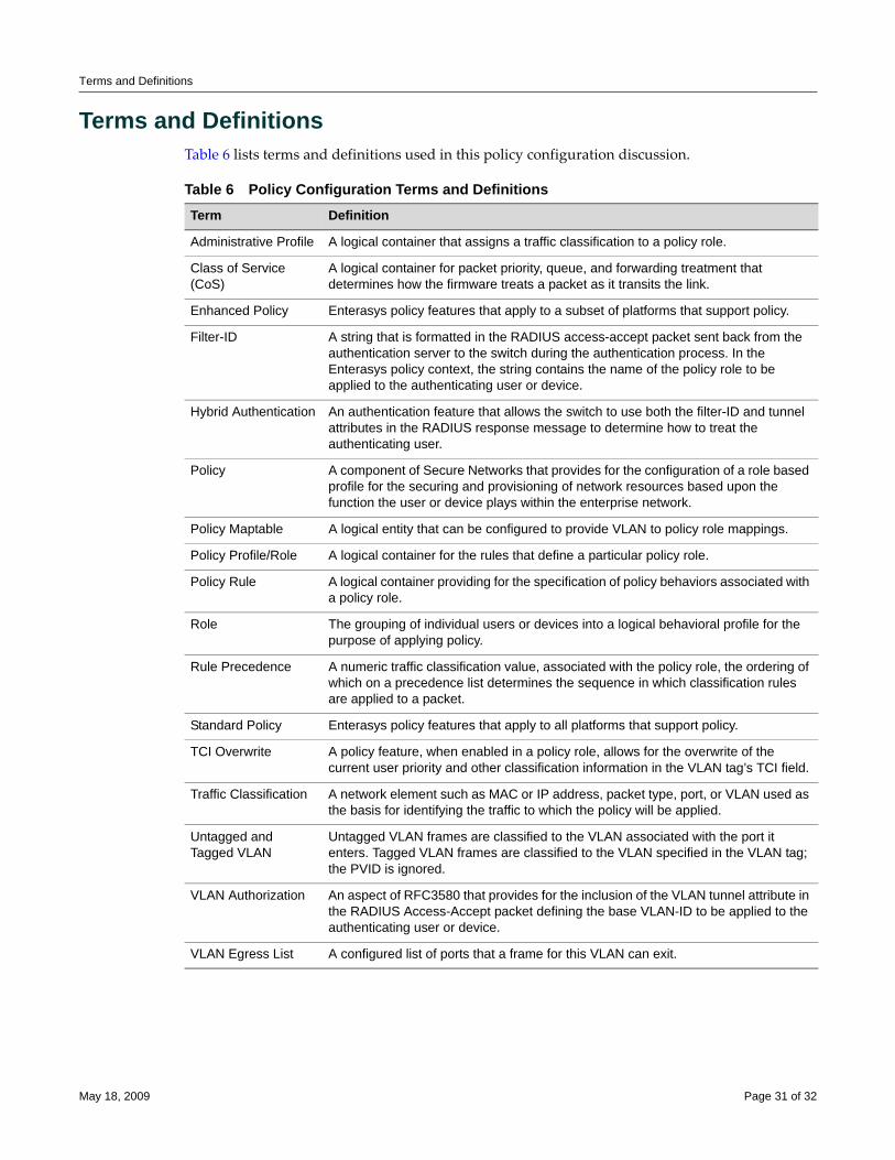
Terms and Definitions
Terms and DefinitionsTable 6 lists terms and definitions used in this policy configuration discussion.
Table 6 Policy Configuration Terms and Definitions Term Definition
Administrative Profile A logical container that assigns a traffic classification to a policy role.
Class of Service (CoS)
A logical container for packet priority, queue, and forwarding treatment that determines how the firmware treats a packet as it transits the link.
Enhanced Policy Enterasys policy features that apply to a subset of platforms that support policy.
Filter-ID A string that is formatted in the RADIUS access-accept packet sent back from the authentication server to the switch during the authentication process. In the Enterasys policy context, the string contains the name of the policy role to be applied to the authenticating user or device.
Hybrid Authentication An authentication feature that allows the switch to use both the filter-ID and tunnel attributes in the RADIUS response message to determine how to treat the authenticating user.
Policy A component of Secure Networks that provides for the configuration of a role based profile for the securing and provisioning of network resources based upon the function the user or device plays within the enterprise network.
Policy Maptable A logical entity that can be configured to provide VLAN to policy role mappings.
Policy Profile/Role A logical container for the rules that define a particular policy role.
Policy Rule A logical container providing for the specification of policy behaviors associated with a policy role.
Role The grouping of individual users or devices into a logical behavioral profile for the purpose of applying policy.
Rule Precedence A numeric traffic classification value, associated with the policy role, the ordering of which on a precedence list determines the sequence in which classification rules are applied to a packet.
Standard Policy Enterasys policy features that apply to all platforms that support policy.
TCI Overwrite A policy feature, when enabled in a policy role, allows for the overwrite of the current user priority and other classification information in the VLAN tag’s TCI field.
Traffic Classification A network element such as MAC or IP address, packet type, port, or VLAN used as the basis for identifying the traffic to which the policy will be applied.
Untagged and Tagged VLAN
Untagged VLAN frames are classified to the VLAN associated with the port it enters. Tagged VLAN frames are classified to the VLAN specified in the VLAN tag; the PVID is ignored.
VLAN Authorization An aspect of RFC3580 that provides for the inclusion of the VLAN tunnel attribute in the RADIUS Access-Accept packet defining the base VLAN-ID to be applied to the authenticating user or device.
VLAN Egress List A configured list of ports that a frame for this VLAN can exit.
May 18, 2009 Page 31 of 32
Revision History
Enterasys Networks reserves the right to make changes in specifications and other information contained in this document and its web site without prior notice. The reader should in all cases consult Enterasys Networks to determine whether any such changes have been made.
The hardware, firmware, or software described in this document is subject to change without notice.
IN NO EVENT SHALL ENTERASYS NETWORKS BE LIABLE FOR ANY INCIDENTAL, INDIRECT, SPECIAL, OR CONSEQUENTIAL DAMAGES WHATSOEVER (INCLUDING BUT NOT LIMITED TO LOST PROFITS) ARISING OUT OF OR RELATED TO THIS DOCUMENT, WEB SITE, OR THE INFORMATION CONTAINED IN THEM, EVEN IF ENTERASYS NETWORKS HAS BEEN ADVISED OF, KNEW OF, OR SHOULD HAVE KNOWN OF, THE POSSIBILITY OF SUCH DAMAGES.
Enterasys Networks, Inc.50 Minuteman RoadAndover, MA 01810
© 2009 Enterasys Networks, Inc. All rights reserved.
ENTERASYS, ENTERASYS NETWORKS, ENTERASYS MATRIX, ENTERASYS NETSIGHT, SECURESTACK, ENTERASYS SECURESTACK, and any logos associated therewith, are trademarks or registered trademarks of Enterasys Networks, Inc., in the United States and other countries. For a complete list of Enterasys trademarks, see http://www.enterasys.com/company/trademarks.aspx.
All other product names mentioned in this manual may be trademarks or registered trademarks of their respective companies.
Date Description
05-18-2009 New Document.
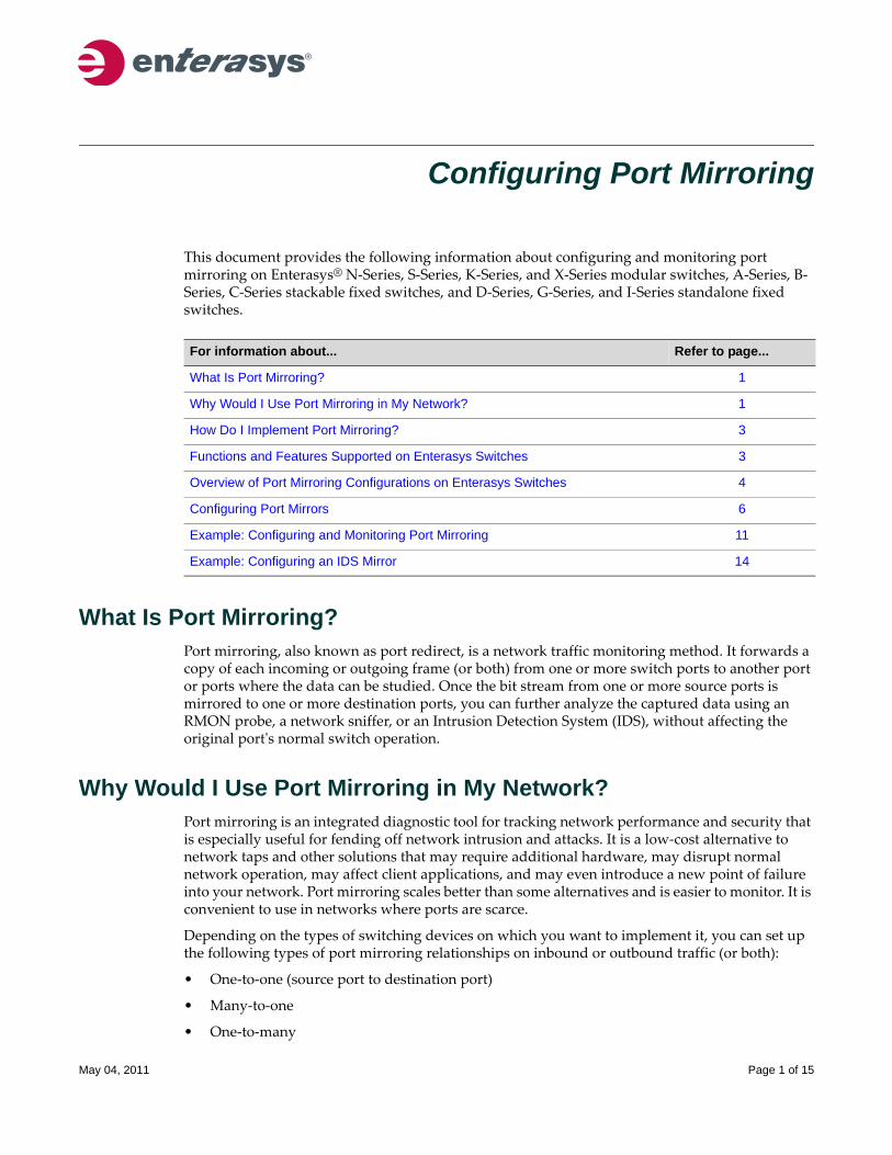
Configuring Port Mirroring
This document provides the following information about configuring and monitoring port mirroring on Enterasys® N‐Series, S‐Series, K‐Series, and X‐Series modular switches, A‐Series, B‐Series, C‐Series stackable fixed switches, and D‐Series, G‐Series, and I‐Series standalone fixed switches.
What Is Port Mirroring?Port mirroring, also known as port redirect, is a network traffic monitoring method. It forwards a copy of each incoming or outgoing frame (or both) from one or more switch ports to another port or ports where the data can be studied. Once the bit stream from one or more source ports is mirrored to one or more destination ports, you can further analyze the captured data using an RMON probe, a network sniffer, or an Intrusion Detection System (IDS), without affecting the original portʹs normal switch operation.
Why Would I Use Port Mirroring in My Network?Port mirroring is an integrated diagnostic tool for tracking network performance and security that is especially useful for fending off network intrusion and attacks. It is a low‐cost alternative to network taps and other solutions that may require additional hardware, may disrupt normal network operation, may affect client applications, and may even introduce a new point of failure into your network. Port mirroring scales better than some alternatives and is easier to monitor. It is convenient to use in networks where ports are scarce.
Depending on the types of switching devices on which you want to implement it, you can set up the following types of port mirroring relationships on inbound or outbound traffic (or both):
• One‐to‐one (source port to destination port)
• Many‐to‐one
• One‐to‐many
For information about... Refer to page...
What Is Port Mirroring? 1
Why Would I Use Port Mirroring in My Network? 1
How Do I Implement Port Mirroring? 3
Functions and Features Supported on Enterasys Switches 3
Overview of Port Mirroring Configurations on Enterasys Switches 4
Configuring Port Mirrors 6
Example: Configuring and Monitoring Port Mirroring 11
Example: Configuring an IDS Mirror 14
May 04, 2011 Page 1 of 15
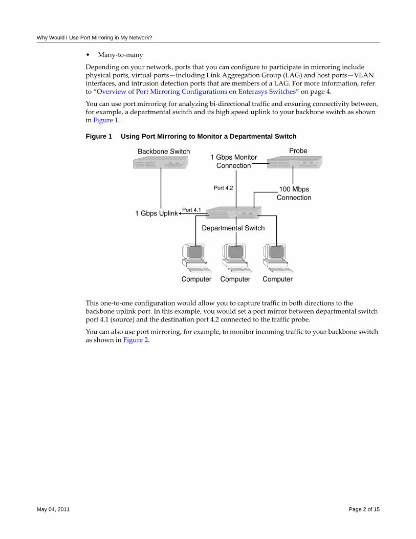
Why Would I Use Port Mirroring in My Network?
• Many‐to‐many
Depending on your network, ports that you can configure to participate in mirroring include physical ports, virtual ports—including Link Aggregation Group (LAG) and host ports—VLAN interfaces, and intrusion detection ports that are members of a LAG. For more information, refer to “Overview of Port Mirroring Configurations on Enterasys Switches” on page 4.
You can use port mirroring for analyzing bi‐directional traffic and ensuring connectivity between, for example, a departmental switch and its high speed uplink to your backbone switch as shown in Figure 1.
Figure 1 Using Port Mirroring to Monitor a Departmental Switch
This one‐to‐one configuration would allow you to capture traffic in both directions to the backbone uplink port. In this example, you would set a port mirror between departmental switch port 4.1 (source) and the destination port 4.2 connected to the traffic probe.
You can also use port mirroring, for example, to monitor incoming traffic to your backbone switch as shown in Figure 2.
May 04, 2011 Page 2 of 15
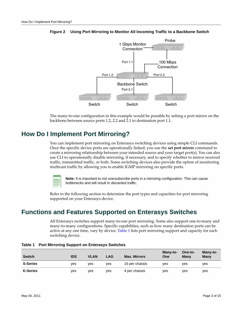
How Do I Implement Port Mirroring?
Figure 2 Using Port Mirroring to Monitor All Incoming Traffic to a Backbone Switch
The many‐to‐one configuration in this example would be possible by setting a port mirror on the backbone between source ports 1.2, 2.2 and 2.1 to destination port 1.1.
How Do I Implement Port Mirroring?You can implement port mirroring on Enterasys switching devices using simple CLI commands. Once the specific device ports are operationally linked, you use the set port mirror command to create a mirroring relationship between your intended source and your target port(s). You can also use CLI to operationally disable mirroring, if necessary, and to specify whether to mirror received traffic, transmitted traffic, or both. Some switching devices also provide the option of monitoring multicast traffic by allowing you to enable IGMP mirroring on specific ports.
Refer to the following section to determine the port types and capacities for port mirroring supported on your Enterasys device.
Functions and Features Supported on Enterasys SwitchesAll Enterasys switches support many‐to‐one port mirroring. Some also support one‐to‐many and many‐to‐many configurations. Specific capabilities, such as how many destination ports can be active at any one time, vary by device. Table 1 lists port mirroring support and capacity for each switching device.
Note: It is important to not oversubscribe ports in a mirroring configuration. This can cause bottlenecks and will result in discarded traffic.
Table 1 Port Mirroring Support on Enterasys Switches
Switch IDS VLAN LAG Max. MirrorsMany-to-One
One-to-Many
Many-to-Many
S-Series yes yes yes 15 per chassis yes yes yes
K-Series yes yes yes 4 per chassis yes yes yes
May 04, 2011 Page 3 of 15
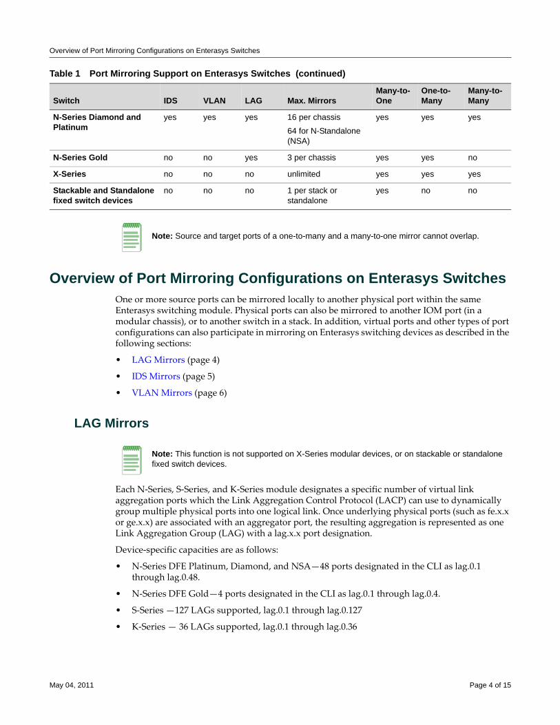
Overview of Port Mirroring Configurations on Enterasys Switches
Overview of Port Mirroring Configurations on Enterasys Switches One or more source ports can be mirrored locally to another physical port within the same Enterasys switching module. Physical ports can also be mirrored to another IOM port (in a modular chassis), or to another switch in a stack. In addition, virtual ports and other types of port configurations can also participate in mirroring on Enterasys switching devices as described in the following sections:
• LAG Mirrors (page 4)
• IDS Mirrors (page 5)
• VLAN Mirrors (page 6)
LAG Mirrors
Each N‐Series, S‐Series, and K‐Series module designates a specific number of virtual link aggregation ports which the Link Aggregation Control Protocol (LACP) can use to dynamically group multiple physical ports into one logical link. Once underlying physical ports (such as fe.x.x or ge.x.x) are associated with an aggregator port, the resulting aggregation is represented as one Link Aggregation Group (LAG) with a lag.x.x port designation.
Device‐specific capacities are as follows:
• N‐Series DFE Platinum, Diamond, and NSA—48 ports designated in the CLI as lag.0.1 through lag.0.48.
• N‐Series DFE Gold—4 ports designated in the CLI as lag.0.1 through lag.0.4.
• S‐Series —127 LAGs supported, lag.0.1 through lag.0.127
• K‐Series — 36 LAGs supported, lag.0.1 through lag.0.36
N-Series Diamond and Platinum
yes yes yes 16 per chassis
64 for N-Standalone (NSA)
yes yes yes
N-Series Gold no no yes 3 per chassis yes yes no
X-Series no no no unlimited yes yes yes
Stackable and Standalone fixed switch devices
no no no 1 per stack or standalone
yes no no
Table 1 Port Mirroring Support on Enterasys Switches (continued)
Switch IDS VLAN LAG Max. MirrorsMany-to-One
One-to-Many
Many-to-Many
Note: Source and target ports of a one-to-many and a many-to-one mirror cannot overlap.
Note: This function is not supported on X-Series modular devices, or on stackable or standalone fixed switch devices.
May 04, 2011 Page 4 of 15
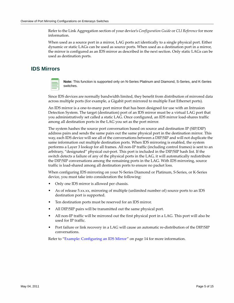
Overview of Port Mirroring Configurations on Enterasys Switches
Refer to the Link Aggregation section of your device’s Configuration Guide or CLI Reference for more information.
When used as a source port in a mirror, LAG ports act identically to a single physical port. Either dynamic or static LAGs can be used as source ports. When used as a destination port in a mirror, the mirror is configured as an IDS mirror as described in the next section. Only static LAGs can be used as destination ports.
IDS Mirrors
Since IDS devices are normally bandwidth limited, they benefit from distribution of mirrored data across multiple ports (for example, a Gigabit port mirrored to multiple Fast Ethernet ports).
An IDS mirror is a one‐to‐many port mirror that has been designed for use with an Intrusion Detection System. The target (destination) port of an IDS mirror must be a virtual LAG port that you administratively set called a static LAG. Once configured, an IDS mirror load‐shares traffic among all destination ports in the LAG you set as the port mirror.
The system hashes the source port conversation based on source and destination IP (SIP/DIP) address pairs and sends the same pairs out the same physical port in the destination mirror. This way, each IDS device will see all of the conversations between a DIP/SIP and will not duplicate the same information out multiple destination ports. When IDS mirroring is enabled, the system performs a Layer 3 lookup for all frames. All non‐IP traffic (including control frames) is sent to an arbitrary, “designated” physical out‐port. This port is included in the DIP/SIP hash list. If the switch detects a failure of any of the physical ports in the LAG, it will automatically redistribute the DIP/SIP conversations among the remaining ports in the LAG. With IDS mirroring, source traffic is load‐shared among all destination ports to ensure no packet loss.
When configuring IDS mirroring on your N‐Series Diamond or Platinum, S‐Series, or K‐Series device, you must take into consideration the following:
• Only one IDS mirror is allowed per chassis.
• As of release 5.xx.xx, mirroring of multiple (unlimited number of) source ports to an IDS destination port is supported.
• Ten destination ports must be reserved for an IDS mirror.
• All DIP/SIP pairs will be transmitted out the same physical port.
• All non‐IP traffic will be mirrored out the first physical port in a LAG. This port will also be used for IP traffic.
• Port failure or link recovery in a LAG will cause an automatic re‐distribution of the DIP/SIP conversations.
Refer to “Example: Configuring an IDS Mirror” on page 14 for more information.
Note: This function is supported only on N-Series Platinum and Diamond, S-Series, and K-Series switches.
May 04, 2011 Page 5 of 15
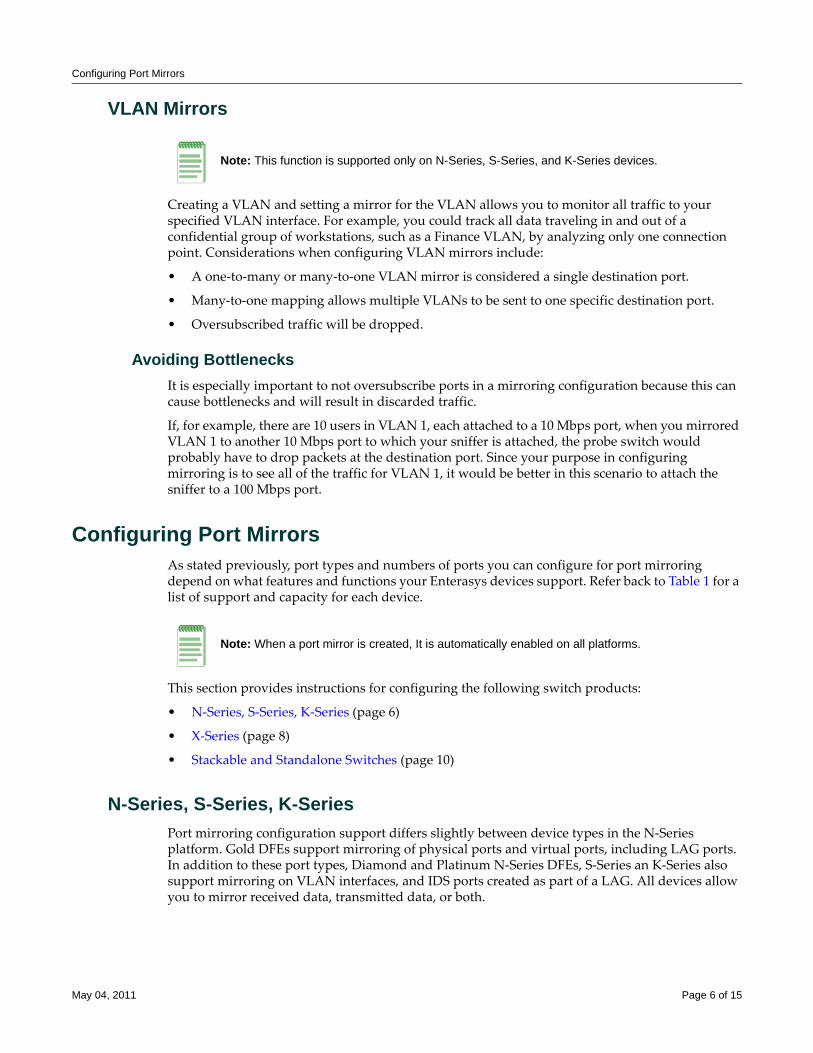
Configuring Port Mirrors
VLAN Mirrors
Creating a VLAN and setting a mirror for the VLAN allows you to monitor all traffic to your specified VLAN interface. For example, you could track all data traveling in and out of a confidential group of workstations, such as a Finance VLAN, by analyzing only one connection point. Considerations when configuring VLAN mirrors include:
• A one‐to‐many or many‐to‐one VLAN mirror is considered a single destination port.
• Many‐to‐one mapping allows multiple VLANs to be sent to one specific destination port.
• Oversubscribed traffic will be dropped.
Avoiding BottlenecksIt is especially important to not oversubscribe ports in a mirroring configuration because this can cause bottlenecks and will result in discarded traffic.
If, for example, there are 10 users in VLAN 1, each attached to a 10 Mbps port, when you mirrored VLAN 1 to another 10 Mbps port to which your sniffer is attached, the probe switch would probably have to drop packets at the destination port. Since your purpose in configuring mirroring is to see all of the traffic for VLAN 1, it would be better in this scenario to attach the sniffer to a 100 Mbps port.
Configuring Port MirrorsAs stated previously, port types and numbers of ports you can configure for port mirroring depend on what features and functions your Enterasys devices support. Refer back to Table 1 for a list of support and capacity for each device.
This section provides instructions for configuring the following switch products:
• N‐Series, S‐Series, K‐Series (page 6)
• X‐Series (page 8)
• Stackable and Standalone Switches (page 10)
N-Series, S-Series, K-SeriesPort mirroring configuration support differs slightly between device types in the N‐Series platform. Gold DFEs support mirroring of physical ports and virtual ports, including LAG ports. In addition to these port types, Diamond and Platinum N‐Series DFEs, S‐Series an K‐Series also support mirroring on VLAN interfaces, and IDS ports created as part of a LAG. All devices allow you to mirror received data, transmitted data, or both.
Note: This function is supported only on N-Series, S-Series, and K-Series devices.
Note: When a port mirror is created, It is automatically enabled on all platforms.
May 04, 2011 Page 6 of 15
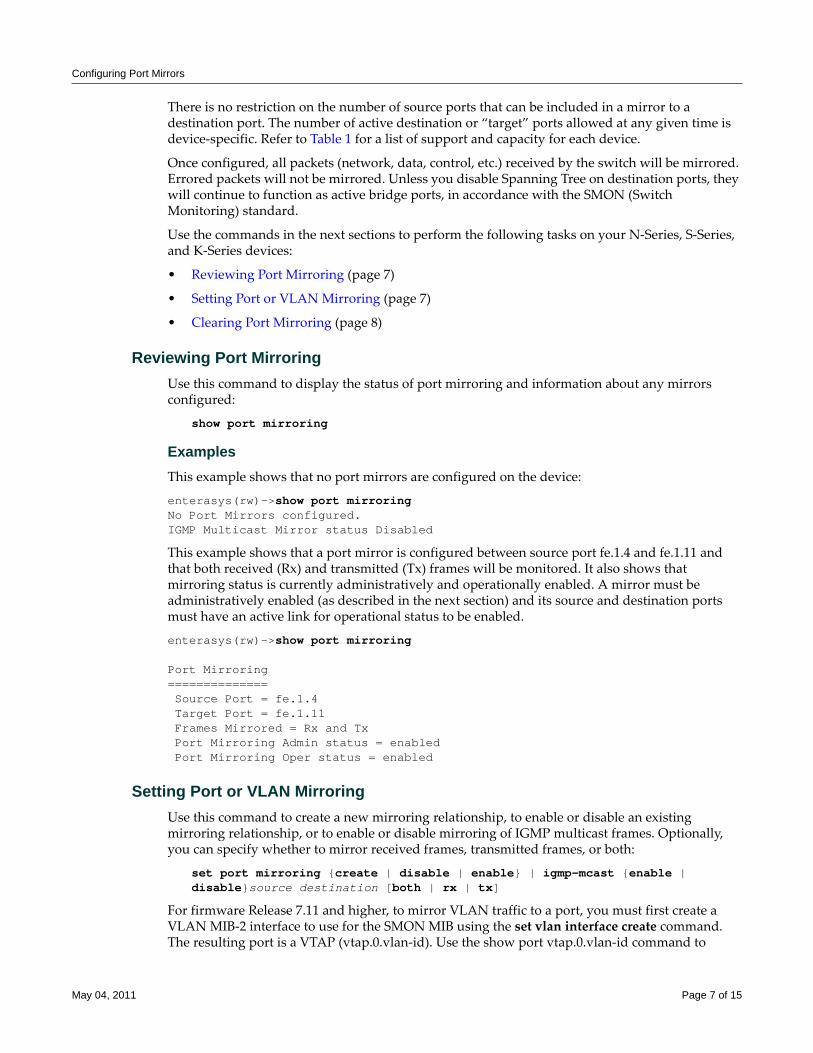
Configuring Port Mirrors
There is no restriction on the number of source ports that can be included in a mirror to a destination port. The number of active destination or “target” ports allowed at any given time is device‐specific. Refer to Table 1 for a list of support and capacity for each device.
Once configured, all packets (network, data, control, etc.) received by the switch will be mirrored. Errored packets will not be mirrored. Unless you disable Spanning Tree on destination ports, they will continue to function as active bridge ports, in accordance with the SMON (Switch Monitoring) standard.
Use the commands in the next sections to perform the following tasks on your N‐Series, S‐Series, and K‐Series devices:
• Reviewing Port Mirroring (page 7)
• Setting Port or VLAN Mirroring (page 7)
• Clearing Port Mirroring (page 8)
Reviewing Port Mirroring Use this command to display the status of port mirroring and information about any mirrors configured:
show port mirroring
ExamplesThis example shows that no port mirrors are configured on the device:
enterasys(rw)->show port mirroringNo Port Mirrors configured.IGMP Multicast Mirror status Disabled
This example shows that a port mirror is configured between source port fe.1.4 and fe.1.11 and that both received (Rx) and transmitted (Tx) frames will be monitored. It also shows that mirroring status is currently administratively and operationally enabled. A mirror must be administratively enabled (as described in the next section) and its source and destination ports must have an active link for operational status to be enabled.
enterasys(rw)->show port mirroring
Port Mirroring============== Source Port = fe.1.4 Target Port = fe.1.11 Frames Mirrored = Rx and TxPort Mirroring Admin status = enabledPort Mirroring Oper status = enabled
Setting Port or VLAN MirroringUse this command to create a new mirroring relationship, to enable or disable an existing mirroring relationship, or to enable or disable mirroring of IGMP multicast frames. Optionally, you can specify whether to mirror received frames, transmitted frames, or both:
set port mirroring {create | disable | enable} | igmp-mcast {enable | disable}source destination [both | rx | tx]
For firmware Release 7.11 and higher, to mirror VLAN traffic to a port, you must first create a VLAN MIB‐2 interface to use for the SMON MIB using the set vlan interface create command. The resulting port is a VTAP (vtap.0.vlan‐id). Use the show port vtap.0.vlan‐id command to
May 04, 2011 Page 7 of 15
Configuring Port Mirrors
display the VTAP port. To create the port mirror use the set port mirroring create command specifying the VTAP and the mirrored port.
If not specified, both received and transmitted frames will be mirrored.
ExamplesThis example shows how to create a port mirror to mirror frames transmitted out port fe.1.4 to port fe.1.11:
enterasys(rw)->set port mirroring enable fe.1.4 fe.1.11 tx
This example shows how to create a many‐to‐one mirroring configuration between source ports fe.1.2, fe.1.3 and fe.1.4, and target port fe.1.10. By default, frames in both directions will be mirrored:
enterasys(rw)->set port mirroring create fe.1.2-4 fe.1.10
This example shows how to configure mirroring from VLANs 5 and 6 to destination port 1 in slot 2 of a DFE chassis (fe.2.1):
enterasys(rw)->set vlan interface 5-6 create enterasys(rw)->set port mirroring create vtap.0.5-6 fe.2.1
Clearing Port MirroringUse this command to clear a port mirroring configuration:
clear port mirroring {igmp-mcast | source destination}
X-Series
The X‐Series Router allows you to mirror (or redirect) received and transmitted traffic being switched on a port for the purposes of network traffic analysis and connection assurance. When port mirroring is enabled, one port becomes a monitor port for another port within the system.
The X Router supports one‐to‐one, one‐to‐many, many‐to‐one, and many‐to‐many mirroring of traffic received and traffic transmitted on physical IOM ports.
Ports must be in switch mode in order to participate in mirroring.
Use the commands in the next sections to perform the following tasks on your X‐Series device:
• Reviewing Port Mirroring (page 9)
• Setting Port Mirroring (page 9)
Note: IGMP mirroring functionality (igmp-mcast) is not supported on N-Series Gold devices.
Note: If you configure a port mirror on an uplink (tagged) port, make sure the port is assigned to egress frames with that VLAN tag. For more information about configuring VLANs, refer to your product’s Configuration Guide.
Notes: VLAN, IDS, and LAG mirroring are not supported on the X-Series.
May 04, 2011 Page 8 of 15
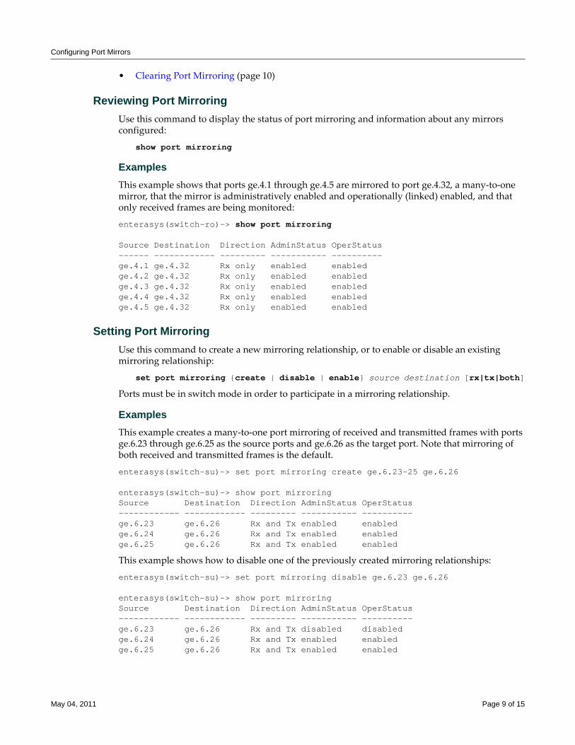
Configuring Port Mirrors
• Clearing Port Mirroring (page 10)
Reviewing Port Mirroring Use this command to display the status of port mirroring and information about any mirrors configured:
show port mirroring
ExamplesThis example shows that ports ge.4.1 through ge.4.5 are mirrored to port ge.4.32, a many‐to‐one mirror, that the mirror is administratively enabled and operationally (linked) enabled, and that only received frames are being monitored:
enterasys(switch-ro)-> show port mirroring
Source Destination Direction AdminStatus OperStatus------ ------------ --------- ----------- ----------ge.4.1 ge.4.32 Rx only enabled enabledge.4.2 ge.4.32 Rx only enabled enabledge.4.3 ge.4.32 Rx only enabled enabledge.4.4 ge.4.32 Rx only enabled enabledge.4.5 ge.4.32 Rx only enabled enabled
Setting Port MirroringUse this command to create a new mirroring relationship, or to enable or disable an existing mirroring relationship:
set port mirroring {create | disable | enable} source destination [rx|tx|both]
Ports must be in switch mode in order to participate in a mirroring relationship.
ExamplesThis example creates a many‐to‐one port mirroring of received and transmitted frames with ports ge.6.23 through ge.6.25 as the source ports and ge.6.26 as the target port. Note that mirroring of both received and transmitted frames is the default.
enterasys(switch-su)-> set port mirroring create ge.6.23-25 ge.6.26
enterasys(switch-su)-> show port mirroringSource Destination Direction AdminStatus OperStatus------------ ------------ --------- ----------- ----------ge.6.23 ge.6.26 Rx and Tx enabled enabledge.6.24 ge.6.26 Rx and Tx enabled enabledge.6.25 ge.6.26 Rx and Tx enabled enabled
This example shows how to disable one of the previously created mirroring relationships:
enterasys(switch-su)-> set port mirroring disable ge.6.23 ge.6.26
enterasys(switch-su)-> show port mirroringSource Destination Direction AdminStatus OperStatus------------ ------------ --------- ----------- ----------ge.6.23 ge.6.26 Rx and Tx disabled disabledge.6.24 ge.6.26 Rx and Tx enabled enabledge.6.25 ge.6.26 Rx and Tx enabled enabled
May 04, 2011 Page 9 of 15
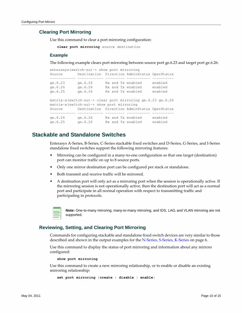
Configuring Port Mirrors
Clearing Port MirroringUse this command to clear a port mirroring configuration:
clear port mirroring source destination
ExampleThe following example clears port mirroring between source port ge.6.23 and target port ge.6.26:
enterasys(switch-su)-> show port mirroringSource Destination Direction AdminStatus OperStatus------------ ------------ --------- ----------- ----------ge.6.23 ge.6.26 Rx and Tx enabled enabledge.6.24 ge.6.26 Rx and Tx enabled enabledge.6.25 ge.6.26 Rx and Tx enabled enabled
matrix-x(switch-su)-> clear port mirroring ge.6.23 ge.6.26matrix-x(switch-su)-> show port mirroringSource Destination Direction AdminStatus OperStatus------------ ------------ --------- ----------- ----------ge.6.24 ge.6.26 Rx and Tx enabled enabledge.6.25 ge.6.26 Rx and Tx enabled enabled
Stackable and Standalone SwitchesEnterasys A‐Series, B‐Series, C‐Series stackable fixed switches and D‐Series, G‐Series, and I‐Series standalone fixed switches support the following mirroring features:
• Mirroring can be configured in a many‐to‐one configuration so that one target (destination) port can monitor traffic on up to 8 source ports.
• Only one mirror destination port can be configured per stack or standalone.
• Both transmit and receive traffic will be mirrored.
• A destination port will only act as a mirroring port when the session is operationally active. If the mirroring session is not operationally active, then the destination port will act as a normal port and participate in all normal operation with respect to transmitting traffic and participating in protocols.
Reviewing, Setting, and Clearing Port MirroringCommands for configuring stackable and standalone fixed switch devices are very similar to those described and shown in the output examples for the N‐Series, S‐Series, K‐Series on page 6.
Use this command to display the status of port mirroring and information about any mirrors configured:
show port mirroring
Use this command to create a new mirroring relationship, or to enable or disable an existing mirroring relationship:
set port mirroring {create | disable | enable}
Note: One-to-many mirroring, many-to-many mirroring, and IDS, LAG, and VLAN mirroring are not supported.
May 04, 2011 Page 10 of 15
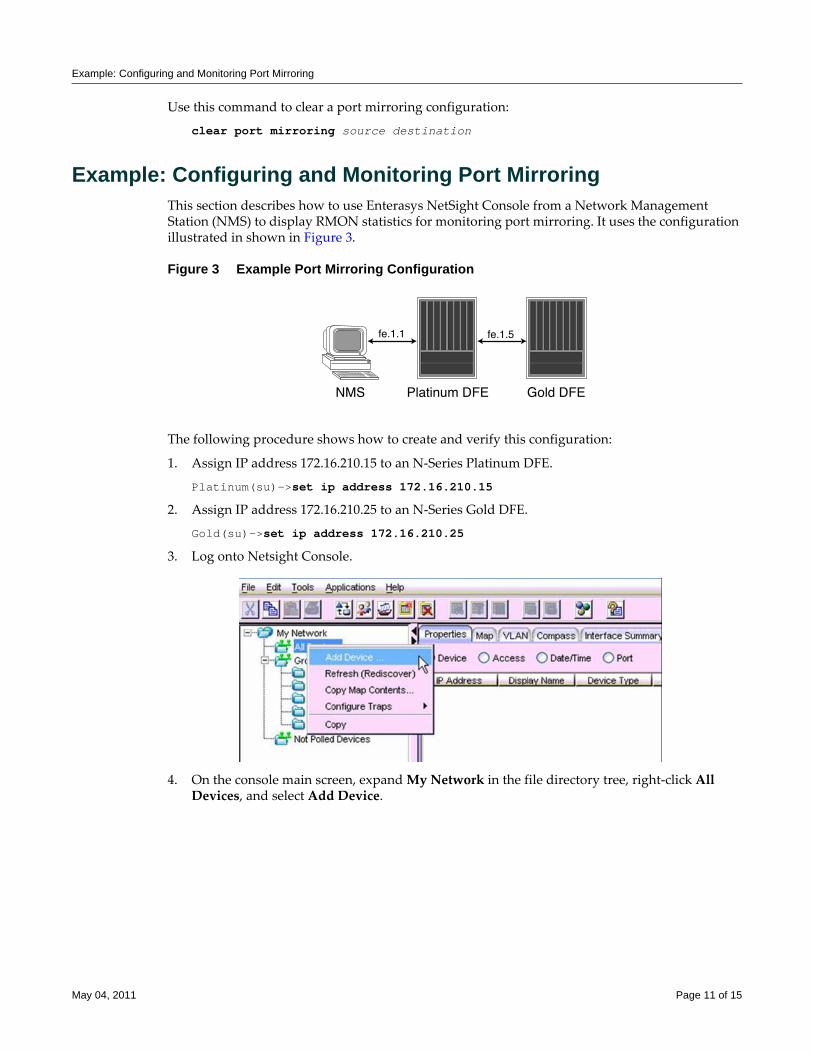
Example: Configuring and Monitoring Port Mirroring
Use this command to clear a port mirroring configuration:
clear port mirroring source destination
Example: Configuring and Monitoring Port MirroringThis section describes how to use Enterasys NetSight Console from a Network Management Station (NMS) to display RMON statistics for monitoring port mirroring. It uses the configuration illustrated in shown in Figure 3.
Figure 3 Example Port Mirroring Configuration
The following procedure shows how to create and verify this configuration:
1. Assign IP address 172.16.210.15 to an N‐Series Platinum DFE.
Platinum(su)->set ip address 172.16.210.15
2. Assign IP address 172.16.210.25 to an N‐Series Gold DFE.
Gold(su)->set ip address 172.16.210.25
3. Log onto Netsight Console.
4. On the console main screen, expand My Network in the file directory tree, right‐click All Devices, and select Add Device.
May 04, 2011 Page 11 of 15
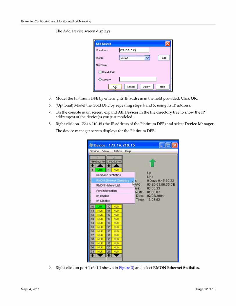
Example: Configuring and Monitoring Port Mirroring
The Add Device screen displays.
5. Model the Platinum DFE by entering its IP address in the field provided. Click OK.
6. (Optional) Model the Gold DFE by repeating steps 4 and 5, using its IP address.
7. On the console main screen, expand All Devices in the file directory tree to show the IP address(es) of the device(s) you just modeled.
8. Right click on 172.16.210.15 (the IP address of the Platinum DFE) and select Device Manager.
The device manager screen displays for the Platinum DFE.
9. Right click on port 1 (fe.1.1 shown in Figure 3) and select RMON Ethernet Statistics.
May 04, 2011 Page 12 of 15
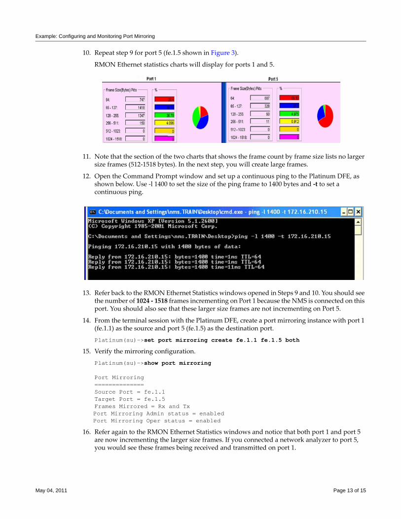
Example: Configuring and Monitoring Port Mirroring
10. Repeat step 9 for port 5 (fe.1.5 shown in Figure 3).
RMON Ethernet statistics charts will display for ports 1 and 5.
11. Note that the section of the two charts that shows the frame count by frame size lists no larger size frames (512‐1518 bytes). In the next step, you will create large frames.
12. Open the Command Prompt window and set up a continuous ping to the Platinum DFE, as shown below. Use ‐l 1400 to set the size of the ping frame to 1400 bytes and ‐t to set a continuous ping.
13. Refer back to the RMON Ethernet Statistics windows opened in Steps 9 and 10. You should see the number of 1024 ‐ 1518 frames incrementing on Port 1 because the NMS is connected on this port. You should also see that these larger size frames are not incrementing on Port 5.
14. From the terminal session with the Platinum DFE, create a port mirroring instance with port 1 (fe.1.1) as the source and port 5 (fe.1.5) as the destination port.
Platinum(su)->set port mirroring create fe.1.1 fe.1.5 both
15. Verify the mirroring configuration.
Platinum(su)->show port mirroring
Port Mirroring==============Source Port = fe.1.1Target Port = fe.1.5Frames Mirrored = Rx and TxPort Mirroring Admin status = enabledPort Mirroring Oper status = enabled
16. Refer again to the RMON Ethernet Statistics windows and notice that both port 1 and port 5 are now incrementing the larger size frames. If you connected a network analyzer to port 5, you would see these frames being received and transmitted on port 1.
May 04, 2011 Page 13 of 15
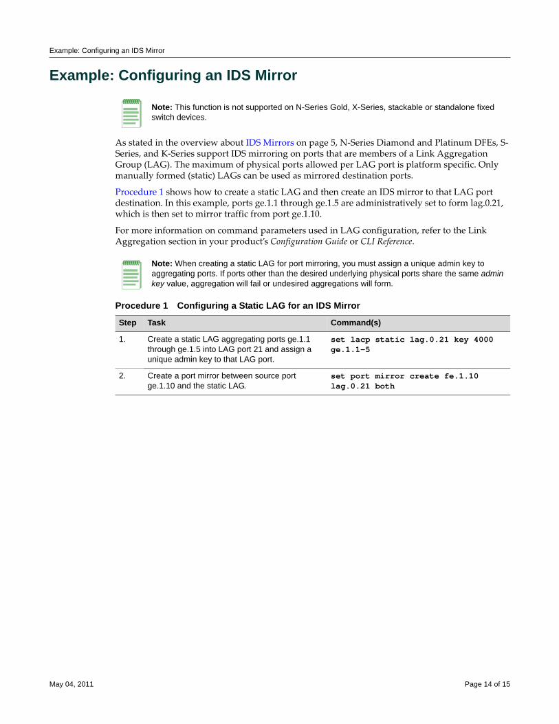
Example: Configuring an IDS Mirror
Example: Configuring an IDS Mirror
As stated in the overview about IDS Mirrors on page 5, N‐Series Diamond and Platinum DFEs, S‐Series, and K‐Series support IDS mirroring on ports that are members of a Link Aggregation Group (LAG). The maximum of physical ports allowed per LAG port is platform specific. Only manually formed (static) LAGs can be used as mirrored destination ports.
Procedure 1 shows how to create a static LAG and then create an IDS mirror to that LAG port destination. In this example, ports ge.1.1 through ge.1.5 are administratively set to form lag.0.21, which is then set to mirror traffic from port ge.1.10.
For more information on command parameters used in LAG configuration, refer to the Link Aggregation section in your product’s Configuration Guide or CLI Reference.
Note: This function is not supported on N-Series Gold, X-Series, stackable or standalone fixed switch devices.
Note: When creating a static LAG for port mirroring, you must assign a unique admin key to aggregating ports. If ports other than the desired underlying physical ports share the same admin key value, aggregation will fail or undesired aggregations will form.
Procedure 1 Configuring a Static LAG for an IDS Mirror
Step Task Command(s)
1. Create a static LAG aggregating ports ge.1.1 through ge.1.5 into LAG port 21 and assign a unique admin key to that LAG port.
set lacp static lag.0.21 key 4000 ge.1.1-5
2. Create a port mirror between source port ge.1.10 and the static LAG.
set port mirror create fe.1.10 lag.0.21 both
May 04, 2011 Page 14 of 15
Enterasys Networks reserves the right to make changes in specifications and other information contained in this document and its web site without prior notice. The reader should in all cases consult Enterasys Networks to determine whether any such changes have been made.
The hardware, firmware, or software described in this document is subject to change without notice.
IN NO EVENT SHALL ENTERASYS NETWORKS BE LIABLE FOR ANY INCIDENTAL, INDIRECT, SPECIAL, OR CONSEQUENTIAL DAMAGES WHATSOEVER (INCLUDING BUT NOT LIMITED TO LOST PROFITS) ARISING OUT OF OR RELATED TO THIS DOCUMENT, WEB SITE, OR THE INFORMATION CONTAINED IN THEM, EVEN IF ENTERASYS NETWORKS HAS BEEN ADVISED OF, KNEW OF, OR SHOULD HAVE KNOWN OF, THE POSSIBILITY OF SUCH DAMAGES.
Enterasys Networks, Inc.50 Minuteman RoadAndover, MA 01810
© 2011 Enterasys Networks, Inc. All rights reserved.
ENTERASYS, ENTERASYS NETWORKS, ENTERASYS NETSIGHT, and any logos associated therewith, are trademarks or registered trademarks of Enterasys Networks, Inc., in the United States and other countries. For a complete list of Enterasys trademarks, see http://www.enterasys.com/company/trademarks.aspx.
All other product names mentioned in this manual may be trademarks or registered trademarks of their respective companies.
Revision History
Date Description
01-16-08 New document
02-20-08 Corrected product naming conventions.
03-12-08 Added statement that VLAN mirroring is not supported on SecureStacks and switches.
07-28-08 Added Enterasys Registration mark.
02-04-09 Spelled out D-Series, G-Series, and I-Series when appropriate.
04-16-09 Added note: port mirrors are automatically enabled on all platforms upon creation.
05-04-2011 Added S-Series and K-Series, other minor changes.
Configuring Quality of Service (QoS)
This chapter provides the following information about configuring and monitoring Quality of Service (QoS) on Enterasys® N‐Series, S‐Series®, and K‐Series modular switches, A‐Series, B‐Series, C‐Series stackable fixed switches, and D‐Series, G‐Series, and I‐Series standalone fixed switches.
What Is Quality of Service?Quality of Service (QoS) is:
• A mechanism for the management of bandwidth
• The ability to give preferential treatment to some packets over others
• Based upon packet classification and forwarding treatment
You configure packet preference and forwarding treatment based upon a flow’s sensitivity to delay, delay variation (jitter), bandwidth, availability, and packet drop.
QoS uses packet priority, in conjunction with queue treatment configuration, to determine the interface’s inbound and forwarding behavior for a packet. Packet preference and forwarding treatment for a given flow can be applied to roles configured in Enterasys policy.
Note: Please see the Enterasys X Secure Core Router Configuration Guide for a complete discussion of QoS as it applies to the X-Series.
For information about... Refer to page...
What Is Quality of Service? 1
Why Would I Use It in My Network? 2
How Can I Implement Quality of Service? 2
Quality of Service Overview 2
CoS Hardware Resource Configuration 13
Feature Differences by Platform 28
The QoS CLI Command Flow 29
QoS Policy-Based Configuration Example 31
Terms and Definitions 36
Note: A flow is a stream of IP packets in which the value of a fixed set of IP packet fields is the same for each packet in the stream. Each packet containing the same value for all of these fields is considered part of the same flow, until flow expiration occurs. If a packet is viewed with any set member field value that is different from any current flow, a new flow is started based upon the set field values for that packet.
May 09, 2011 Page 1 of 38
Why Would I Use It in My Network?
The S‐Series Flex‐Edge feature, supported only on S‐Series switches, provides the unique capability to classify and prioritize traffic as it enters the switch, assert flow control, and ensure that higher priority traffic received by the switch is forwarded to the packet processor ahead of lower priority traffic. A separate feature guide exists for the S‐Series Flex‐Edge feature and can be found at https://extranet.enterasys.com/downloads.
Why Would I Use It in My Network?Without QoS, all packets are treated as though the delivery requirements and characteristics of any given packet are equal to any other packet. In other words, non‐QoS packet delivery is not able to take into account application sensitivity to packet delay, jitter, amount of bandwidth required, packet loss, or availability requirements of the flow. QoS provides management mechanisms for these flow characteristics.
How Can I Implement Quality of Service?QoS determines how a flow will be treated as it transits the link. To determine how a flow should be treated, you must first understand the characteristics of the flows on your network, and secondly, you must identify these flows in a way that QoS can recognize. In this sense, QoS is the third step in a three step process. The three‐steps Enterasys recommends for configuring QoS are:
• Understand your network flows using NetFlow
• Associate the flows on your network with a well defined role using Enterasys policy
• Configure the appropriate link behavior for that role by associating the role with a QoS configuration
Quality of Service OverviewQoS is all about managing the bandwidth in a manner that aligns the delivery requirements of a given flow with the available port resources. In a QoS context, a flow is a stream of packets that are classified with the same class of service as the packets transit the interface. QoS manages bandwidth for each flow by:
• Assigning different priority levels to different packet flows.
• Marking or re‐marking the packet priority at port ingress with a Type of Service (ToS).
• Sorting flows by transit queue. Higher priority queues get preferential access to bandwidth during packet forwarding.
• Limiting the amount of bandwidth available to a given flow by either dropping (rate limiting) or buffering (rate shaping) packets in excess of configured limits.
These QoS abilities collectively make up a Class of Service (CoS). The remainder of this section will describe CoS and its components.
Note: The following overview and configuration discussion will take place in an S-Series context. See Feature Differences by Platform on page 28 for a listing of CoS feature differences.
May 09, 2011 Page 2 of 38
Quality of Service Overview
Class of Service (CoS)You implement QoS features in a Class of Service (CoS). There are four hardware resource components that can be configured as part of a CoS.
• Transmit Queues (TxQ) ‐ represent the queuing hardware resources for each port that are used in scheduling packets for egressing the device, as well as rate shaping of traffic based upon outbound buffering.
• Inbound Rate Limiters (IRL) ‐ allow you to configure a threshold above which a port will not process traffic.
• Outbound Rate Limiters (ORL) ‐ allow you to configure a threshold above which a port will not transmit traffic.
• Flood Control ‐ configures a threshold above which a port will not receive unknown‐unicast, multicast, or broadcast packets.
The CoS configuration of each queue or port hardware resource is optional. TxQs have three configurable queue options: queue mapping, queue rate shaping and queue scheduling. IRL, ORL, and flood control each have a single configurable rate limiting port hardware resource option.
CoS configuration is applied to the ingressing packet based upon the packet’s 802.1 priority, port, and policy settings.
How the firmware treats a packet as it transits the link depends upon the priority and forwarding treatments configured in the CoS assigned to the packet. Up to 256 unique CoS entries can be configured. CoS entries 0–7 are configured by default with an 802.1p priority assigned and default forwarding treatment. CoS entries 0–7 cannot be removed. CoS entries 0–7 are reserved for mapping an 802.1p priority to a CoS index. CoS entries 8‐255 can be configured and used by policy for the following services:
• 802.1p priority
• IP Type of Service (ToS) marking
• Priority Transmit Queue (TxQ) with configurable forwarding behavior
• In‐bound (IRL) and/or outbound (ORL) rate limiter
• Outbound rate shaper per transmit queue
• Flood control
There are up to four areas of CoS configuration depending on what type of hardware resource you want to configure. The terminology associated with CoS configuration is introduced in Table 1.
Table 1 CoS Configuration TerminologyTerm Description
CoS Setting Maps configured resources to a CoS index. When a packet is received, the packet is mapped to a CoS index based on the packet 802.1 priority, port, and policy role, if a policy role is present. The CoS index translates into available hardware resources through indirect mappings to TxQ, IRL, ORL, or the administrative state of flood control. An optional drop precedence can be configured.
CoS Reference Provides a means of mapping a CoS setting to a specific hardware resource, such as a TxQ, IRL, or ORL.
May 09, 2011 Page 3 of 38
Quality of Service Overview
CoS SettingsUse the CoS settings configuration when mapping the priority of the ingressing packet to a hardware resource reference, flood control state, drop precedence behavior, or 802.1 priority or ToS remarking.
CoS Hardware Resource ReferenceThe CoS hardware resource reference can be:
• A reference to a transmit queue. On the S‐Series, valid values are 0 ‐ 10.
• An inbound rate limiter reference. On the S‐Series, valid values are 0 ‐ 31.
• An outbound rate limiter reference. On the S‐Series, valid values are 0 ‐ 3.
CoS Flood Control StateCoS flood control state enables or disables flood control for the CoS setting.
CoS Priority and ToS RewriteThe two parameters configurable for CoS priority are 802.1p and Type of Service (ToS). Each CoS can be mapped to an 802.1p priority and a ToS rewrite value. 802.1p and ToS are specified in the CoS settings configuration layer.
The 802.1p parameter is:
• A subset of ToS with values 0–7 (upper 3 bits of the 8 bit ToS field)
• Supported in both layer 2 and layer 3
The ToS parameter is:
• An 8‐bit field with values 0–255
• Supported in layer 3 only
• Also referred to as the Differentiated Services Code Point (DSCP) when limited to the lower 5 bits of the field
Figure 1 displays the relationship between your application, priority level, 802.1p, and ToS assignments (shown here using DSCP terminology).
QoS priority/ToS configuration:
• Derives its characteristic requirements from the end‐system application.
• Is configured on the edge device the application is connected to
• Is propagated through the network in the protocol packet header
CoS Port Resource Specifies the transmit queue rate shaping or IRL, ORL, or flood control rate limiter threshold value that the CoS reference is mapped to.
CoS Port Configuration Specifies the ports to which CoS resource configuration should be applied, and provides for TxQ scheduling.
Table 1 CoS Configuration Terminology (continued)Term Description
May 09, 2011 Page 4 of 38
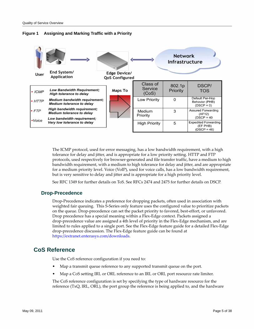
Quality of Service Overview
Figure 1 Assigning and Marking Traffic with a Priority
The ICMP protocol, used for error messaging, has a low bandwidth requirement, with a high tolerance for delay and jitter, and is appropriate for a low priority setting. HTTP and FTP protocols, used respectively for browser‐generated and file transfer traffic, have a medium to high bandwidth requirement, with a medium to high tolerance for delay and jitter, and are appropriate for a medium priority level. Voice (VoIP), used for voice calls, has a low bandwidth requirement, but is very sensitive to delay and jitter and is appropriate for a high priority level.
See RFC 1349 for further details on ToS. See RFCs 2474 and 2475 for further details on DSCP.
Drop-PrecedenceDrop‐Precedence indicates a preference for dropping packets, often used in association with weighted fair queuing. This S‐Series only feature uses the configured value to prioritize packets on the queue. Drop‐precedence can set the packet priority to favored, best‐effort, or unfavored. Drop precedence has a special meaning within a Flex‐Edge context. Packets assigned a drop‐precedence value are assigned a 4th level of priority in the Flex‐Edge mechanism, and are limited to rules applied to a single port. See the Flex‐Edge feature guide for a detailed Flex‐Edge drop‐precedence discussion. The Flex‐Edge feature guide can be found at https://extranet.enterasys.com/downloads.
CoS ReferenceUse the CoS reference configuration if you need to:
• Map a transmit queue reference to any supported transmit queue on the port.
• Map a CoS setting IRL or ORL reference to an IRL or ORL port resource rate limiter.
The CoS reference configuration is set by specifying the type of hardware resource for the reference (TxQ, IRL, ORL), the port group the reference is being applied to, and the hardware
May 09, 2011 Page 5 of 38
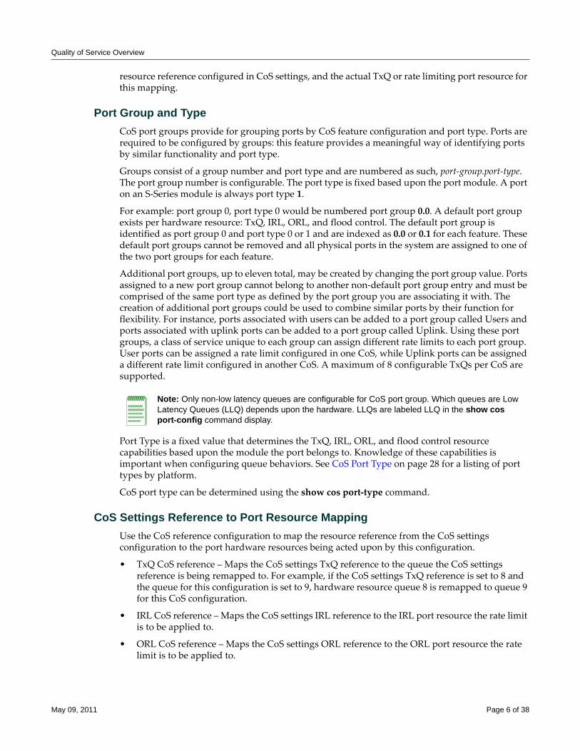
Quality of Service Overview
resource reference configured in CoS settings, and the actual TxQ or rate limiting port resource for this mapping.
Port Group and TypeCoS port groups provide for grouping ports by CoS feature configuration and port type. Ports are required to be configured by groups: this feature provides a meaningful way of identifying ports by similar functionality and port type.
Groups consist of a group number and port type and are numbered as such, port‐group.port‐type. The port group number is configurable. The port type is fixed based upon the port module. A port on an S‐Series module is always port type 1.
For example: port group 0, port type 0 would be numbered port group 0.0. A default port group exists per hardware resource: TxQ, IRL, ORL, and flood control. The default port group is identified as port group 0 and port type 0 or 1 and are indexed as 0.0 or 0.1 for each feature. These default port groups cannot be removed and all physical ports in the system are assigned to one of the two port groups for each feature.
Additional port groups, up to eleven total, may be created by changing the port group value. Ports assigned to a new port group cannot belong to another non‐default port group entry and must be comprised of the same port type as defined by the port group you are associating it with. The creation of additional port groups could be used to combine similar ports by their function for flexibility. For instance, ports associated with users can be added to a port group called Users and ports associated with uplink ports can be added to a port group called Uplink. Using these port groups, a class of service unique to each group can assign different rate limits to each port group. User ports can be assigned a rate limit configured in one CoS, while Uplink ports can be assigned a different rate limit configured in another CoS. A maximum of 8 configurable TxQs per CoS are supported.
Port Type is a fixed value that determines the TxQ, IRL, ORL, and flood control resource capabilities based upon the module the port belongs to. Knowledge of these capabilities is important when configuring queue behaviors. See CoS Port Type on page 28 for a listing of port types by platform.
CoS port type can be determined using the show cos port‐type command.
CoS Settings Reference to Port Resource MappingUse the CoS reference configuration to map the resource reference from the CoS settings configuration to the port hardware resources being acted upon by this configuration.
• TxQ CoS reference – Maps the CoS settings TxQ reference to the queue the CoS settings reference is being remapped to. For example, if the CoS settings TxQ reference is set to 8 and the queue for this configuration is set to 9, hardware resource queue 8 is remapped to queue 9 for this CoS configuration.
• IRL CoS reference – Maps the CoS settings IRL reference to the IRL port resource the rate limit is to be applied to.
• ORL CoS reference – Maps the CoS settings ORL reference to the ORL port resource the rate limit is to be applied to.
Note: Only non-low latency queues are configurable for CoS port group. Which queues are Low Latency Queues (LLQ) depends upon the hardware. LLQs are labeled LLQ in the show cos port-config command display.
May 09, 2011 Page 6 of 38
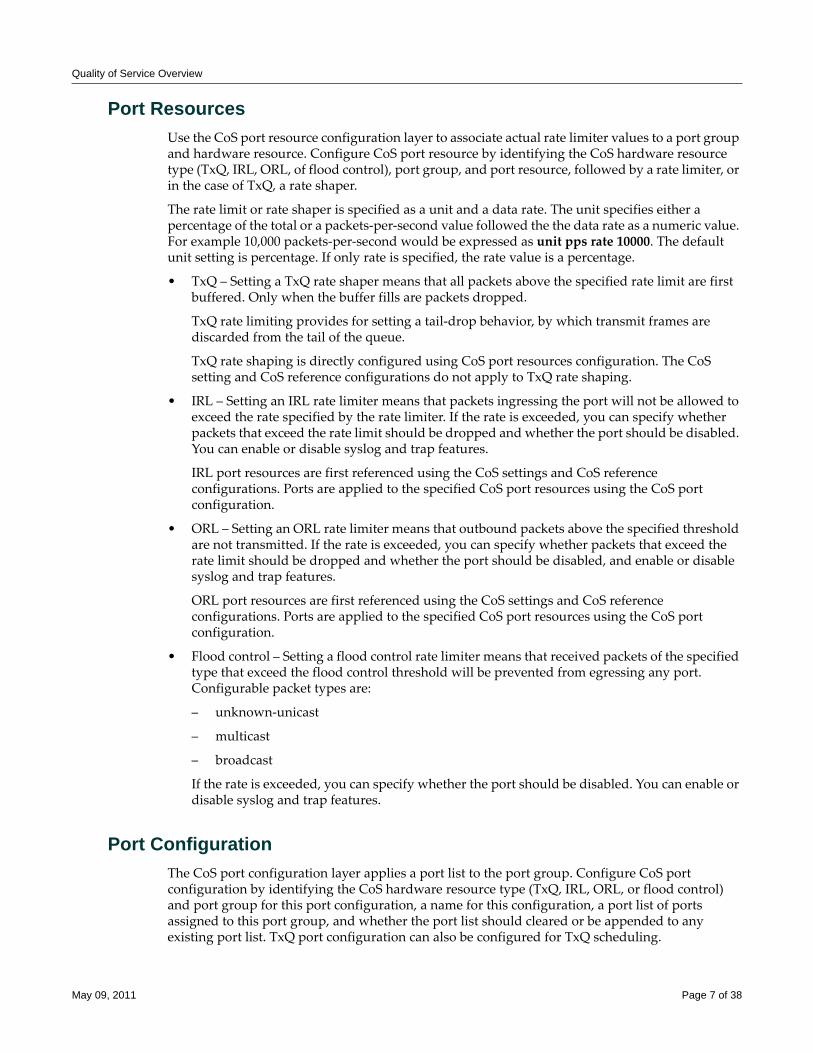
Quality of Service Overview
Port ResourcesUse the CoS port resource configuration layer to associate actual rate limiter values to a port group and hardware resource. Configure CoS port resource by identifying the CoS hardware resource type (TxQ, IRL, ORL, of flood control), port group, and port resource, followed by a rate limiter, or in the case of TxQ, a rate shaper.
The rate limit or rate shaper is specified as a unit and a data rate. The unit specifies either a percentage of the total or a packets‐per‐second value followed the the data rate as a numeric value. For example 10,000 packets‐per‐second would be expressed as unit pps rate 10000. The default unit setting is percentage. If only rate is specified, the rate value is a percentage.
• TxQ – Setting a TxQ rate shaper means that all packets above the specified rate limit are first buffered. Only when the buffer fills are packets dropped.
TxQ rate limiting provides for setting a tail‐drop behavior, by which transmit frames are discarded from the tail of the queue.
TxQ rate shaping is directly configured using CoS port resources configuration. The CoS setting and CoS reference configurations do not apply to TxQ rate shaping.
• IRL – Setting an IRL rate limiter means that packets ingressing the port will not be allowed to exceed the rate specified by the rate limiter. If the rate is exceeded, you can specify whether packets that exceed the rate limit should be dropped and whether the port should be disabled. You can enable or disable syslog and trap features.
IRL port resources are first referenced using the CoS settings and CoS reference configurations. Ports are applied to the specified CoS port resources using the CoS port configuration.
• ORL – Setting an ORL rate limiter means that outbound packets above the specified threshold are not transmitted. If the rate is exceeded, you can specify whether packets that exceed the rate limit should be dropped and whether the port should be disabled, and enable or disable syslog and trap features.
ORL port resources are first referenced using the CoS settings and CoS reference configurations. Ports are applied to the specified CoS port resources using the CoS port configuration.
• Flood control – Setting a flood control rate limiter means that received packets of the specified type that exceed the flood control threshold will be prevented from egressing any port. Configurable packet types are:
– unknown‐unicast
– multicast
– broadcast
If the rate is exceeded, you can specify whether the port should be disabled. You can enable or disable syslog and trap features.
Port ConfigurationThe CoS port configuration layer applies a port list to the port group. Configure CoS port configuration by identifying the CoS hardware resource type (TxQ, IRL, ORL, or flood control) and port group for this port configuration, a name for this configuration, a port list of ports assigned to this port group, and whether the port list should cleared or be appended to any existing port list. TxQ port configuration can also be configured for TxQ scheduling.
May 09, 2011 Page 7 of 38
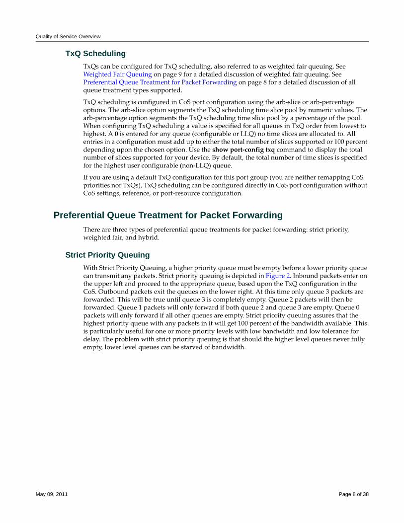
Quality of Service Overview
TxQ SchedulingTxQs can be configured for TxQ scheduling, also referred to as weighted fair queuing. See Weighted Fair Queuing on page 9 for a detailed discussion of weighted fair queuing. See Preferential Queue Treatment for Packet Forwarding on page 8 for a detailed discussion of all queue treatment types supported.
TxQ scheduling is configured in CoS port configuration using the arb‐slice or arb‐percentage options. The arb‐slice option segments the TxQ scheduling time slice pool by numeric values. The arb‐percentage option segments the TxQ scheduling time slice pool by a percentage of the pool. When configuring TxQ scheduling a value is specified for all queues in TxQ order from lowest to highest. A 0 is entered for any queue (configurable or LLQ) no time slices are allocated to. All entries in a configuration must add up to either the total number of slices supported or 100 percent depending upon the chosen option. Use the show port‐config txq command to display the total number of slices supported for your device. By default, the total number of time slices is specified for the highest user configurable (non‐LLQ) queue.
If you are using a default TxQ configuration for this port group (you are neither remapping CoS priorities nor TxQs), TxQ scheduling can be configured directly in CoS port configuration without CoS settings, reference, or port‐resource configuration.
Preferential Queue Treatment for Packet ForwardingThere are three types of preferential queue treatments for packet forwarding: strict priority, weighted fair, and hybrid.
Strict Priority QueuingWith Strict Priority Queuing, a higher priority queue must be empty before a lower priority queue can transmit any packets. Strict priority queuing is depicted in Figure 2. Inbound packets enter on the upper left and proceed to the appropriate queue, based upon the TxQ configuration in the CoS. Outbound packets exit the queues on the lower right. At this time only queue 3 packets are forwarded. This will be true until queue 3 is completely empty. Queue 2 packets will then be forwarded. Queue 1 packets will only forward if both queue 2 and queue 3 are empty. Queue 0 packets will only forward if all other queues are empty. Strict priority queuing assures that the highest priority queue with any packets in it will get 100 percent of the bandwidth available. This is particularly useful for one or more priority levels with low bandwidth and low tolerance for delay. The problem with strict priority queuing is that should the higher level queues never fully empty, lower level queues can be starved of bandwidth.
May 09, 2011 Page 8 of 38
Quality of Service Overview
Figure 2 Strict Priority Queuing Packet Behavior
Low Latency QueuingA Low Latency Queue (LLQ) is a non‐configurable strict priority queue. LLQs are designed to guard against:
• Packet loss
• Delay
• Jitter
LLQ hardware resources can not be configured, but a policy can be configured for a CoS that is mapped to an LLQ. In this way, traffic associated with high value real‐time voice or video packets can be mapped to an LLQ. The LLQ priority will determine when mapped traffic will be serviced relative to other traffic. For example, S‐Series queues 0, 9, and 10 are LLQs. If a voice policy is mapped to a CoS with a TxQ reference that is in turn mapped to queue 9, this voice traffic will be serviced as soon as queue 10 is empty and will continue to be serviced ahead of any lower priority queue until there is no traffic left in queue 9.
LLQs are hardware dependent. Not all hardware devices support low latency queuing. Use the show cos port‐config txq command to display LLQs for a given module.
Weighted Fair QueuingWith weighted fair queuing, queue access to bandwidth is divided up by percentages of the time slices available. For example, if 100 percent is divided into 64 time slices, and each queue is configured for 25 percent, each queue will get 16 time slices, after which the next lowest priority queue will get the next 16, and so on. Should a queue empty before using its current share of time slices, the remaining time slices are shared with all remaining queues. Figure 3 depicts how weighted fair queuing works. Inbound packets enter on the upper left of the box and proceed to the appropriate priority queue. Outbound packets exit the queues on the lower right. Queue 3 has
May 09, 2011 Page 9 of 38
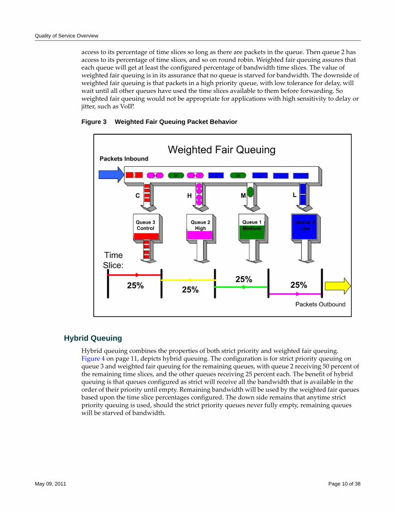
Quality of Service Overview
access to its percentage of time slices so long as there are packets in the queue. Then queue 2 has access to its percentage of time slices, and so on round robin. Weighted fair queuing assures that each queue will get at least the configured percentage of bandwidth time slices. The value of weighted fair queuing is in its assurance that no queue is starved for bandwidth. The downside of weighted fair queuing is that packets in a high priority queue, with low tolerance for delay, will wait until all other queues have used the time slices available to them before forwarding. So weighted fair queuing would not be appropriate for applications with high sensitivity to delay or jitter, such as VoIP.
Figure 3 Weighted Fair Queuing Packet Behavior
Hybrid QueuingHybrid queuing combines the properties of both strict priority and weighted fair queuing. Figure 4 on page 11, depicts hybrid queuing. The configuration is for strict priority queuing on queue 3 and weighted fair queuing for the remaining queues, with queue 2 receiving 50 percent of the remaining time slices, and the other queues receiving 25 percent each. The benefit of hybrid queuing is that queues configured as strict will receive all the bandwidth that is available in the order of their priority until empty. Remaining bandwidth will be used by the weighted fair queues based upon the time slice percentages configured. The down side remains that anytime strict priority queuing is used, should the strict priority queues never fully empty, remaining queues will be starved of bandwidth.
May 09, 2011 Page 10 of 38
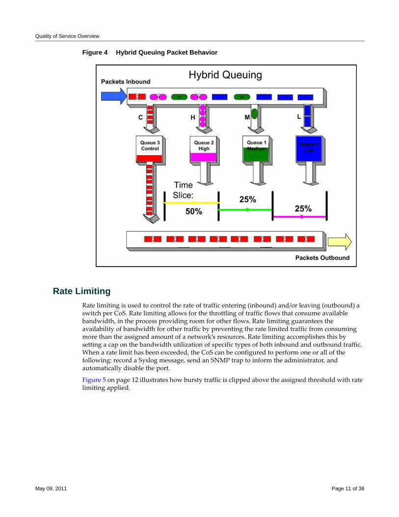
Quality of Service Overview
Figure 4 Hybrid Queuing Packet Behavior
Rate LimitingRate limiting is used to control the rate of traffic entering (inbound) and/or leaving (outbound) a switch per CoS. Rate limiting allows for the throttling of traffic flows that consume available bandwidth, in the process providing room for other flows. Rate limiting guarantees the availability of bandwidth for other traffic by preventing the rate limited traffic from consuming more than the assigned amount of a network’s resources. Rate limiting accomplishes this by setting a cap on the bandwidth utilization of specific types of both inbound and outbound traffic. When a rate limit has been exceeded, the CoS can be configured to perform one or all of the following: record a Syslog message, send an SNMP trap to inform the administrator, and automatically disable the port.
Figure 5 on page 12 illustrates how bursty traffic is clipped above the assigned threshold with rate limiting applied.
May 09, 2011 Page 11 of 38
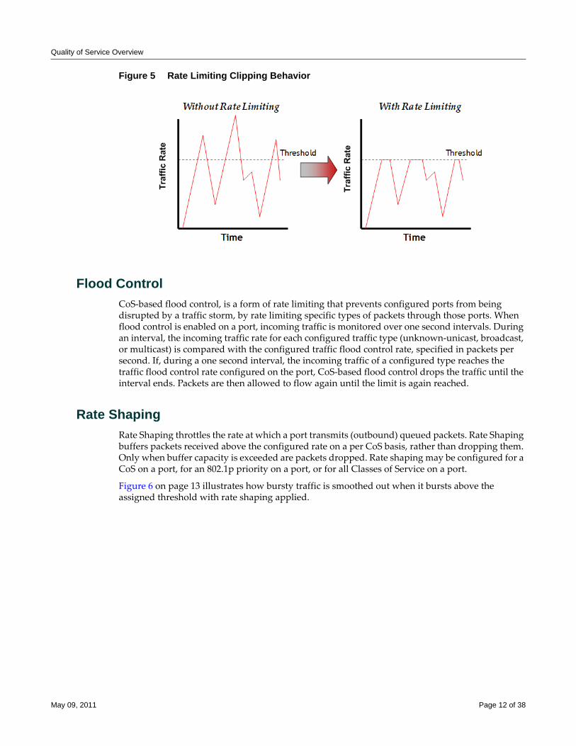
Quality of Service Overview
Figure 5 Rate Limiting Clipping Behavior
Flood ControlCoS‐based flood control, is a form of rate limiting that prevents configured ports from being disrupted by a traffic storm, by rate limiting specific types of packets through those ports. When flood control is enabled on a port, incoming traffic is monitored over one second intervals. During an interval, the incoming traffic rate for each configured traffic type (unknown‐unicast, broadcast, or multicast) is compared with the configured traffic flood control rate, specified in packets per second. If, during a one second interval, the incoming traffic of a configured type reaches the traffic flood control rate configured on the port, CoS‐based flood control drops the traffic until the interval ends. Packets are then allowed to flow again until the limit is again reached.
Rate ShapingRate Shaping throttles the rate at which a port transmits (outbound) queued packets. Rate Shaping buffers packets received above the configured rate on a per CoS basis, rather than dropping them. Only when buffer capacity is exceeded are packets dropped. Rate shaping may be configured for a CoS on a port, for an 802.1p priority on a port, or for all Classes of Service on a port.
Figure 6 on page 13 illustrates how bursty traffic is smoothed out when it bursts above the assigned threshold with rate shaping applied.
May 09, 2011 Page 12 of 38
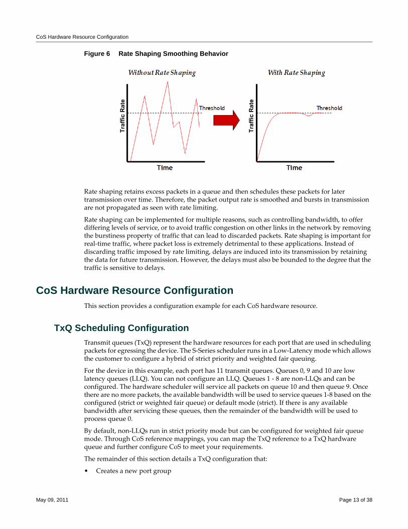
CoS Hardware Resource Configuration
Figure 6 Rate Shaping Smoothing Behavior
Rate shaping retains excess packets in a queue and then schedules these packets for later transmission over time. Therefore, the packet output rate is smoothed and bursts in transmission are not propagated as seen with rate limiting.
Rate shaping can be implemented for multiple reasons, such as controlling bandwidth, to offer differing levels of service, or to avoid traffic congestion on other links in the network by removing the burstiness property of traffic that can lead to discarded packets. Rate shaping is important for real‐time traffic, where packet loss is extremely detrimental to these applications. Instead of discarding traffic imposed by rate limiting, delays are induced into its transmission by retaining the data for future transmission. However, the delays must also be bounded to the degree that the traffic is sensitive to delays.
CoS Hardware Resource ConfigurationThis section provides a configuration example for each CoS hardware resource.
TxQ Scheduling ConfigurationTransmit queues (TxQ) represent the hardware resources for each port that are used in scheduling packets for egressing the device. The S‐Series scheduler runs in a Low‐Latency mode which allows the customer to configure a hybrid of strict priority and weighted fair queuing.
For the device in this example, each port has 11 transmit queues. Queues 0, 9 and 10 are low latency queues (LLQ). You can not configure an LLQ. Queues 1 ‐ 8 are non‐LLQs and can be configured. The hardware scheduler will service all packets on queue 10 and then queue 9. Once there are no more packets, the available bandwidth will be used to service queues 1‐8 based on the configured (strict or weighted fair queue) or default mode (strict). If there is any available bandwidth after servicing these queues, then the remainder of the bandwidth will be used to process queue 0.
By default, non‐LLQs run in strict priority mode but can be configured for weighted fair queue mode. Through CoS reference mappings, you can map the TxQ reference to a TxQ hardware queue and further configure CoS to meet your requirements.
The remainder of this section details a TxQ configuration that:
• Creates a new port group
May 09, 2011 Page 13 of 38
CoS Hardware Resource Configuration
• Names the port group
• Assigns ports to the port group
• Configures non‐LLQ queues for weighted fair queuing
• Maps references to both a best effort and a control queue, based on the already existing LLQs on the device
• Maps CoS priority settings to the queues
• Enables CoS
• Provides related show command displays
CoS Port Configuration LayerFor the CoS port configuration layer, use the set cos port‐config txq command to:
• Configure a new port group template 1.0
• Name the port group template WFQConfiguration
• Assign ports ge.1.3, ge.1.5 and ge.1.22 to port group 1.0
• Configure queues 1 ‐ 8 as weighted fair queues by time slice:
– Queue 1 – 0
– Queue 2 – 0
– Queue 3 – 10
– Queue 4 – 10
– Queue 5 – 15
– Queue 6 – 15
– Queue 7 – 20
– Queue 8 – 30
When configuring weighted fair queues, configured percentages must add up to 100% of the supported time slices. In this case, the port supports 100 time slices.
CoS port Configuration CLI input:
System(su)->set cos port-config txq 1.0 name WFQConfiguration ports ge.1.3,5,22 arb-slice 0,0,0,10,10,15,15,20,30,0,0
CoS TxQ Reference Configuration LayerBy default, TxQ references 1 ‐ 8 map to hardware queues 1 ‐ 8. We are going to remap TxQ reference 1 to queue 0 and TxQ reference 8 to queue 9. This will allow TxQ reference 1 to be our best effort queue which will only be serviced if all other queues are empty.
TxQ reference 8 will be for critical traffic and will be serviced before any other configurable queue. TxQ references 2‐7 will be serviced based on WFQ.
The CoS TxQ reference layer mappings to queues are configured using the set cos reference txq command. CoS TxQ reference mapping CLI input:
System(su)->set cos reference txq 1.0 1 queue 0
System(su)->set cos reference txq 1.0 8 queue 9
May 09, 2011 Page 14 of 38
CoS Hardware Resource Configuration
CoS Settings Configuration LayerThe final step is to assign the CoS indexes to the TxQ references. In this example, CoS Index 0 (802.1 priority 0) will be our best effort traffic, COS Index 7 (802.1 priority 7) will be assigned to our critical queue. All other priorities will map to the WFQs.
System(su)->set cos settings 0 txq-reference 1
System(su)->set cos settings 2 txq-reference 3
System(su)->set cos settings 3 txq-reference 4
System(su)->set cos settings 4 txq-reference 5
System(su)->set cos settings 5 txq-reference 6
System(su)->set cos settings 6 txq-reference 7
System(su)->set cos settings 7 txq-reference 8
Enable CoS StateCoS configuration must be enabled to become active, using the set cos state enable command:
System(su)->set cos state enable
TxQ Configuration Example Show Command OutputUse the show cos settings command to display CoS settings layer configuration:
System(su)->show cos settings
* Means attribute has not been configured
CoS Index Priority ToS TxQ IRL ORL Drop Prec Flood-Ctrl
--------- ---------- ------- ----- ----- ----- --------- ----------
0 0 * 1 * * * Disabled
1 1 * 2 * * * Disabled
2 2 * 3 * * * Disabled
3 3 * 4 * * * Disabled
4 4 * 5 * * * Disabled
5 5 * 6 * * * Disabled
6 6 * 7 * * * Disabled
7 7 * 8 * * * Disabled
Use the show cos reference txq command to display the CoS reference configuration for port group 1.0:
System(su)->show cos reference txq 1.0
Group Index Reference Type Queue
----------- --------- ---- ------------
1.0 0 txq 0
1.0 1 txq 0
1.0 2 txq 2
1.0 3 txq 3
May 09, 2011 Page 15 of 38
CoS Hardware Resource Configuration
1.0 4 txq 4
1.0 5 txq 5
1.0 6 txq 6
1.0 7 txq 7
1.0 8 txq 9
1.0 9 txq 8
1.0 10 txq 8
1.0 11 txq 8
1.0 12 txq 8
1.0 13 txq 8
1.0 14 txq 9
1.0 15 txq 10
Use the show cos port‐config txq command to display the CoS port layer configuration:
System(su)->show cos port-config txq 1.0
* Percentage/queue (if any) are approximations based on
[(slices/queue) / total number of slices]
Transmit Queue Port Configuration Entries
----------------------------------------------------------------------
Port Group Name :WFQConfiguration
Port Group :1
Port Type :0
Assigned Ports :ge.1.3,5,22
Arbiter Mode :Low Latency Queue
Slices/queue :Q [ 0]: LLQ Q [ 1]: 0 Q [ 2]: 0 Q [ 3]: 10
:Q [ 4]: 10 Q [ 5]: 15 Q [ 6]: 15 Q [ 7]: 20
:Q [ 8]: 30 Q [ 9]: LLQ Q [10]: LLQ
Percentage/queue :Q [ 0]: LLQ Q [ 1]: 0% Q [ 2]: 0% Q [ 3]: 10%
:Q [ 4]: 10% Q [ 5]: 15% Q [ 6]: 15% Q [ 7]: 20%
:Q [ 8]: 30% Q [ 9]: LLQ Q [10]: LLQ
----------------------------------------------------------------------
TxQ Rate Shaping ConfigurationEach transmit queue has the capability to rate shape all traffic being transmitted on the queue. In this example, we configure port ge.2.17 to rate shape all traffic egressing transmit queue 8 (the actual hardware queue, not the TxQ reference) to a threshold of 50% of the ports bandwidth. All queues remain in the default strict priority mode. Any traffic exceeding this amount will be first buffered and rescheduled for transmission. Buffered traffic is only dropped if the buffer fills. Rate shaping provides two services. The buffering of excess packets assures that traffic in excess of the configured value will be rescheduled and transmitted as long as the buffers do not fill. The limit specified assures that lower queues are serviced in an oversubscription situation based upon the default strict priority mode behavior.
May 09, 2011 Page 16 of 38
CoS Hardware Resource Configuration
The remainder of this section details a TxQ rate shaping configuration that:
• Configures port group 2.0 for port ge.2.17
• Names port group 2.0 txqRateShaper
• Configures all other ports for port group 0.0
• Sets the port resource rate for port group 2.0 on queue 8 to 50% of port bandwidth
• Enables CoS
• Provides related show command displays
CoS Port Configuration LayerFor the CoS port configuration layer, use the set cos port‐config txq command to:
• Configure port group template 0.0 for all ports on the device except for ge.2.17
• Configure port group template 2.0 for port ge.2.17
• Name port group template 2.0 txqRateShaper
CoS port Configuration CLI input:
System(su)->set cos port-config txq 0.0 ports ge.2.1-16,18-48;tg.2.101-104
System(su)->set cos port-config txq 2.0 name txqRateShaper ports ge.2.17
CoS TxQ Port Resource LayerIt is at the port resource TxQ configuration layer that the bandwidth rate shaper, over which all packets are buffered, is applied to a hardware queue. We will apply a bandwidth rate of 50% to TxQ queue 8 for port group 2.0.
System(su)->set cos port-resource txq 2.0 8 unit percentage rate 50
Enable CoS StateCoS configuration must be enabled to become active, using the set cos state enable command:
System(su)->set cos state enable
TxQ Rate Shaping Configuration Example Show Command OutputNo CoS Settings configuration was required for this example. The CoS settings show command will display the default configuration. Use the show cos settings command to display CoS settings layer configuration:
System(su)->show cos settings
* Means attribute has not been configured
CoS Index Priority ToS TxQ IRL ORL Drop Prec Flood-Ctrl
--------- ---------- ------- ----- ----- ----- --------- ----------
0 0 * 0 * * * Disabled
1 1 * 2 * * * Disabled
2 2 * 4 * * * Disabled
May 09, 2011 Page 17 of 38
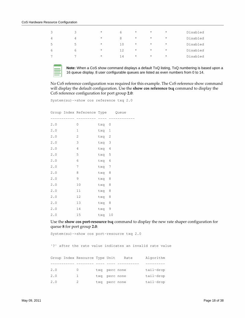
CoS Hardware Resource Configuration
3 3 * 6 * * * Disabled
4 4 * 8 * * * Disabled
5 5 * 10 * * * Disabled
6 6 * 12 * * * Disabled
7 7 * 14 * * * Disabled
No CoS reference configuration was required for this example. The CoS reference show command will display the default configuration. Use the show cos reference txq command to display the CoS reference configuration for port group 2.0:
System(su)->show cos reference txq 2.0
Group Index Reference Type Queue
----------- --------- ---- ------------
2.0 0 txq 0
2.0 1 txq 1
2.0 2 txq 2
2.0 3 txq 3
2.0 4 txq 4
2.0 5 txq 5
2.0 6 txq 6
2.0 7 txq 7
2.0 8 txq 8
2.0 9 txq 8
2.0 10 txq 8
2.0 11 txq 8
2.0 12 txq 8
2.0 13 txq 8
2.0 14 txq 9
2.0 15 txq 10
Use the show cos port‐resource txq command to display the new rate shaper configuration for queue 8 for port group 2.0:
System(su)->show cos port-resource txq 2.0
'?' after the rate value indicates an invalid rate value
Group Index Resource Type Unit Rate Algorithm
----------- -------- ---- ---- ---------- ---------
2.0 0 txq perc none tail-drop
2.0 1 txq perc none tail-drop
2.0 2 txq perc none tail-drop
Note: When a CoS show command displays a default TxQ listing, TxQ numbering is based upon a 16 queue display. 8 user configurable queues are listed as even numbers from 0 to 14.
May 09, 2011 Page 18 of 38
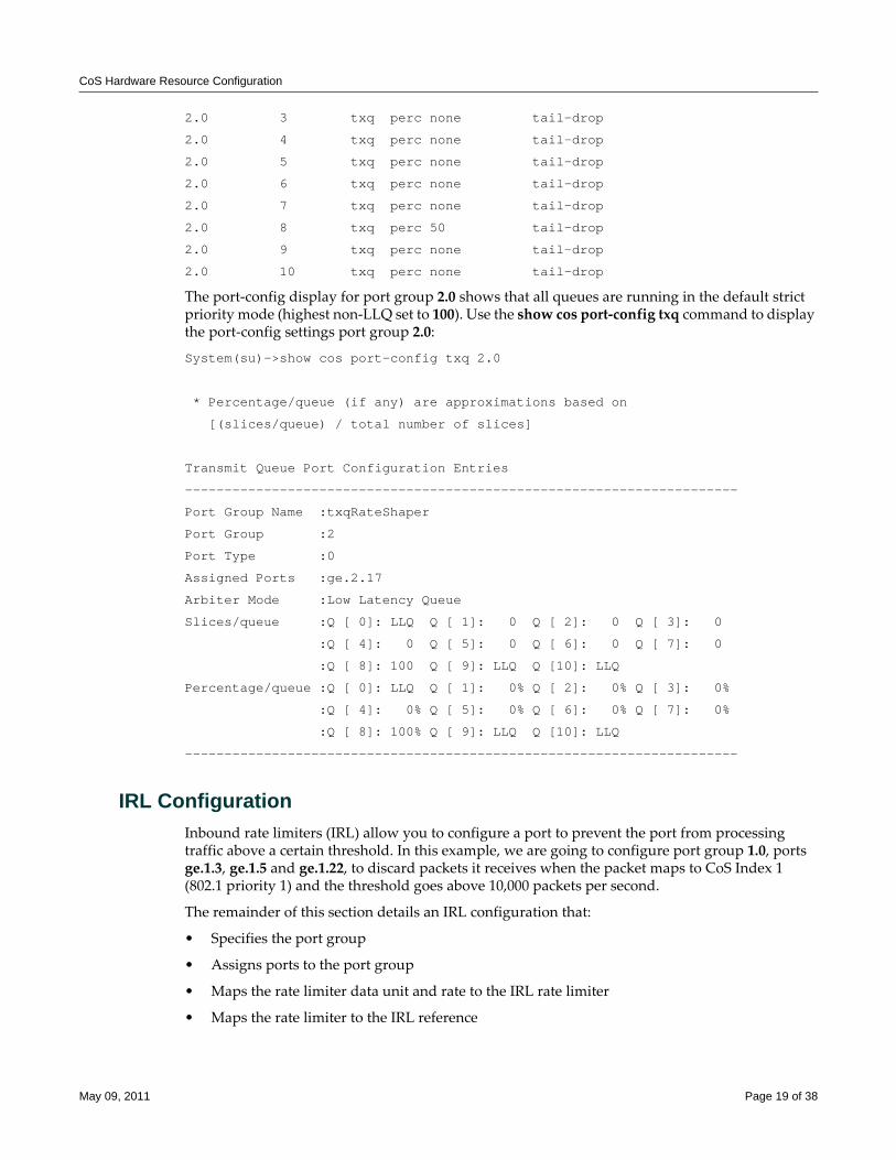
CoS Hardware Resource Configuration
2.0 3 txq perc none tail-drop
2.0 4 txq perc none tail-drop
2.0 5 txq perc none tail-drop
2.0 6 txq perc none tail-drop
2.0 7 txq perc none tail-drop
2.0 8 txq perc 50 tail-drop
2.0 9 txq perc none tail-drop
2.0 10 txq perc none tail-drop
The port‐config display for port group 2.0 shows that all queues are running in the default strict priority mode (highest non‐LLQ set to 100). Use the show cos port‐config txq command to display the port‐config settings port group 2.0:
System(su)->show cos port-config txq 2.0
* Percentage/queue (if any) are approximations based on
[(slices/queue) / total number of slices]
Transmit Queue Port Configuration Entries
----------------------------------------------------------------------
Port Group Name :txqRateShaper
Port Group :2
Port Type :0
Assigned Ports :ge.2.17
Arbiter Mode :Low Latency Queue
Slices/queue :Q [ 0]: LLQ Q [ 1]: 0 Q [ 2]: 0 Q [ 3]: 0
:Q [ 4]: 0 Q [ 5]: 0 Q [ 6]: 0 Q [ 7]: 0
:Q [ 8]: 100 Q [ 9]: LLQ Q [10]: LLQ
Percentage/queue :Q [ 0]: LLQ Q [ 1]: 0% Q [ 2]: 0% Q [ 3]: 0%
:Q [ 4]: 0% Q [ 5]: 0% Q [ 6]: 0% Q [ 7]: 0%
:Q [ 8]: 100% Q [ 9]: LLQ Q [10]: LLQ
----------------------------------------------------------------------
IRL ConfigurationInbound rate limiters (IRL) allow you to configure a port to prevent the port from processing traffic above a certain threshold. In this example, we are going to configure port group 1.0, ports ge.1.3, ge.1.5 and ge.1.22, to discard packets it receives when the packet maps to CoS Index 1 (802.1 priority 1) and the threshold goes above 10,000 packets per second.
The remainder of this section details an IRL configuration that:
• Specifies the port group
• Assigns ports to the port group
• Maps the rate limiter data unit and rate to the IRL rate limiter
• Maps the rate limiter to the IRL reference
May 09, 2011 Page 19 of 38
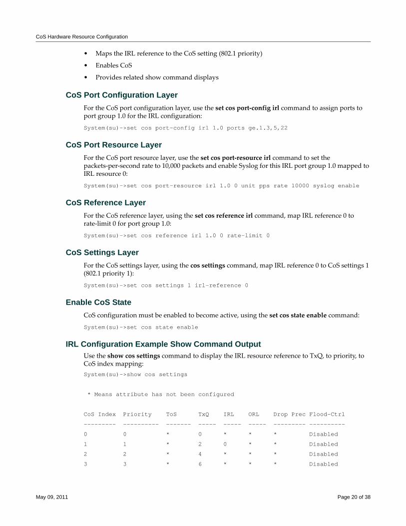
CoS Hardware Resource Configuration
• Maps the IRL reference to the CoS setting (802.1 priority)
• Enables CoS
• Provides related show command displays
CoS Port Configuration LayerFor the CoS port configuration layer, use the set cos port‐config irl command to assign ports to port group 1.0 for the IRL configuration:
System(su)->set cos port-config irl 1.0 ports ge.1.3,5,22
CoS Port Resource LayerFor the CoS port resource layer, use the set cos port‐resource irl command to set the packets‐per‐second rate to 10,000 packets and enable Syslog for this IRL port group 1.0 mapped to IRL resource 0:
System(su)->set cos port-resource irl 1.0 0 unit pps rate 10000 syslog enable
CoS Reference LayerFor the CoS reference layer, using the set cos reference irl command, map IRL reference 0 to rate‐limit 0 for port group 1.0:
System(su)->set cos reference irl 1.0 0 rate-limit 0
CoS Settings LayerFor the CoS settings layer, using the cos settings command, map IRL reference 0 to CoS settings 1 (802.1 priority 1):
System(su)->set cos settings 1 irl-reference 0
Enable CoS StateCoS configuration must be enabled to become active, using the set cos state enable command:
System(su)->set cos state enable
IRL Configuration Example Show Command OutputUse the show cos settings command to display the IRL resource reference to TxQ, to priority, to CoS index mapping:System(su)->show cos settings
* Means attribute has not been configured
CoS Index Priority ToS TxQ IRL ORL Drop Prec Flood-Ctrl
--------- ---------- ------- ----- ----- ----- --------- ----------
0 0 * 0 * * * Disabled
1 1 * 2 0 * * Disabled
2 2 * 4 * * * Disabled
3 3 * 6 * * * Disabled
May 09, 2011 Page 20 of 38
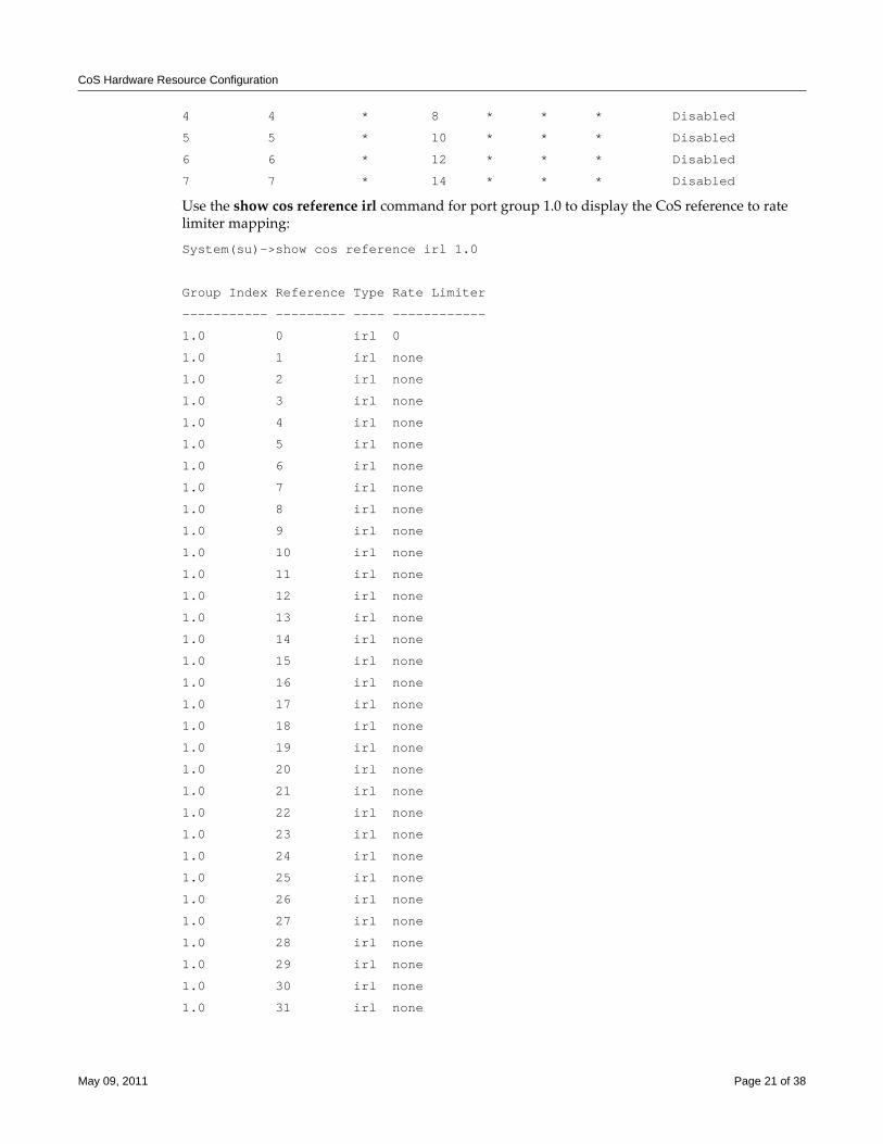
CoS Hardware Resource Configuration
4 4 * 8 * * * Disabled
5 5 * 10 * * * Disabled
6 6 * 12 * * * Disabled
7 7 * 14 * * * Disabled
Use the show cos reference irl command for port group 1.0 to display the CoS reference to rate limiter mapping:
System(su)->show cos reference irl 1.0
Group Index Reference Type Rate Limiter
----------- --------- ---- ------------
1.0 0 irl 0
1.0 1 irl none
1.0 2 irl none
1.0 3 irl none
1.0 4 irl none
1.0 5 irl none
1.0 6 irl none
1.0 7 irl none
1.0 8 irl none
1.0 9 irl none
1.0 10 irl none
1.0 11 irl none
1.0 12 irl none
1.0 13 irl none
1.0 14 irl none
1.0 15 irl none
1.0 16 irl none
1.0 17 irl none
1.0 18 irl none
1.0 19 irl none
1.0 20 irl none
1.0 21 irl none
1.0 22 irl none
1.0 23 irl none
1.0 24 irl none
1.0 25 irl none
1.0 26 irl none
1.0 27 irl none
1.0 28 irl none
1.0 29 irl none
1.0 30 irl none
1.0 31 irl none
May 09, 2011 Page 21 of 38

CoS Hardware Resource Configuration
Use the show cos port‐resource irl command to display the data rate and unit of the rate limiter for port 1.0:
System(su)->show cos port-resource irl 1.0
'?' after the rate value indicates an invalid rate value
Group Index Resource Type Unit Rate Rate Limit Type Action
----------- -------- ---- ---- ---------- --------------- ------
1.0 0 irl pps 10000 drop S
1.0 1 irl perc none drop none
1.0 2 irl perc none drop none
1.0 3 irl perc none drop none
1.0 4 irl perc none drop none
1.0 5 irl perc none drop none
1.0 6 irl perc none drop none
1.0 7 irl perc none drop none
1.0 8 irl perc none drop none
1.0 9 irl perc none drop none
1.0 10 irl perc none drop none
1.0 11 irl perc none drop none
1.0 12 irl perc none drop none
1.0 13 irl perc none drop none
1.0 14 irl perc none drop none
1.0 15 irl perc none drop none
1.0 16 irl perc none drop none
1.0 17 irl perc none drop none
1.0 18 irl perc none drop none
1.0 19 irl perc none drop none
1.0 20 irl perc none drop none
1.0 21 irl perc none drop none
1.0 22 irl perc none drop none
1.0 23 irl perc none drop none
Use the show cos port‐config irl command to display the port group name and assigned ports for port group 1.0:
System(su)->show cos port-config irl 1.0
Inbound Rate Limiting Port Configuration Entries
----------------------------------------------------------------------
Port Group Name :S-Series 24 IRL
Port Group :1
Port Type :0
Assigned Ports :ge.1.3,5,22
May 09, 2011 Page 22 of 38
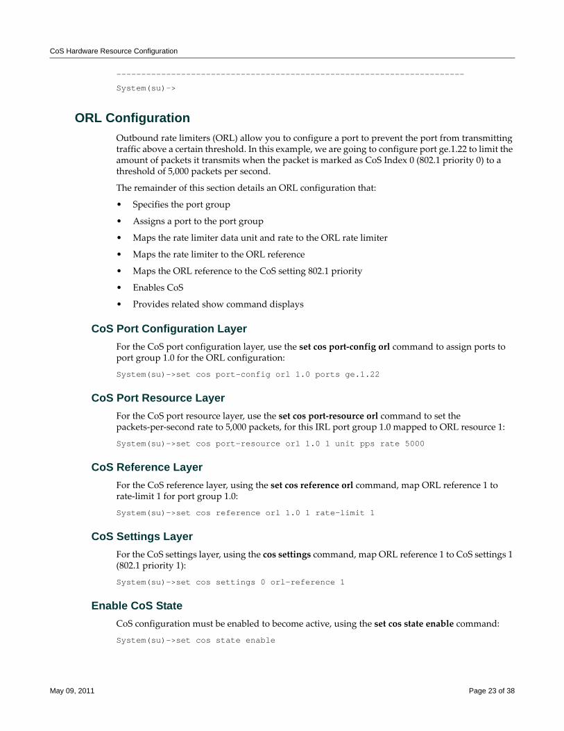
CoS Hardware Resource Configuration
----------------------------------------------------------------------
System(su)->
ORL ConfigurationOutbound rate limiters (ORL) allow you to configure a port to prevent the port from transmitting traffic above a certain threshold. In this example, we are going to configure port ge.1.22 to limit the amount of packets it transmits when the packet is marked as CoS Index 0 (802.1 priority 0) to a threshold of 5,000 packets per second.
The remainder of this section details an ORL configuration that:
• Specifies the port group
• Assigns a port to the port group
• Maps the rate limiter data unit and rate to the ORL rate limiter
• Maps the rate limiter to the ORL reference
• Maps the ORL reference to the CoS setting 802.1 priority
• Enables CoS
• Provides related show command displays
CoS Port Configuration LayerFor the CoS port configuration layer, use the set cos port‐config orl command to assign ports to port group 1.0 for the ORL configuration:
System(su)->set cos port-config orl 1.0 ports ge.1.22
CoS Port Resource LayerFor the CoS port resource layer, use the set cos port‐resource orl command to set the packets‐per‐second rate to 5,000 packets, for this IRL port group 1.0 mapped to ORL resource 1:
System(su)->set cos port-resource orl 1.0 1 unit pps rate 5000
CoS Reference LayerFor the CoS reference layer, using the set cos reference orl command, map ORL reference 1 to rate‐limit 1 for port group 1.0:
System(su)->set cos reference orl 1.0 1 rate-limit 1
CoS Settings LayerFor the CoS settings layer, using the cos settings command, map ORL reference 1 to CoS settings 1 (802.1 priority 1):
System(su)->set cos settings 0 orl-reference 1
Enable CoS StateCoS configuration must be enabled to become active, using the set cos state enable command:
System(su)->set cos state enable
May 09, 2011 Page 23 of 38
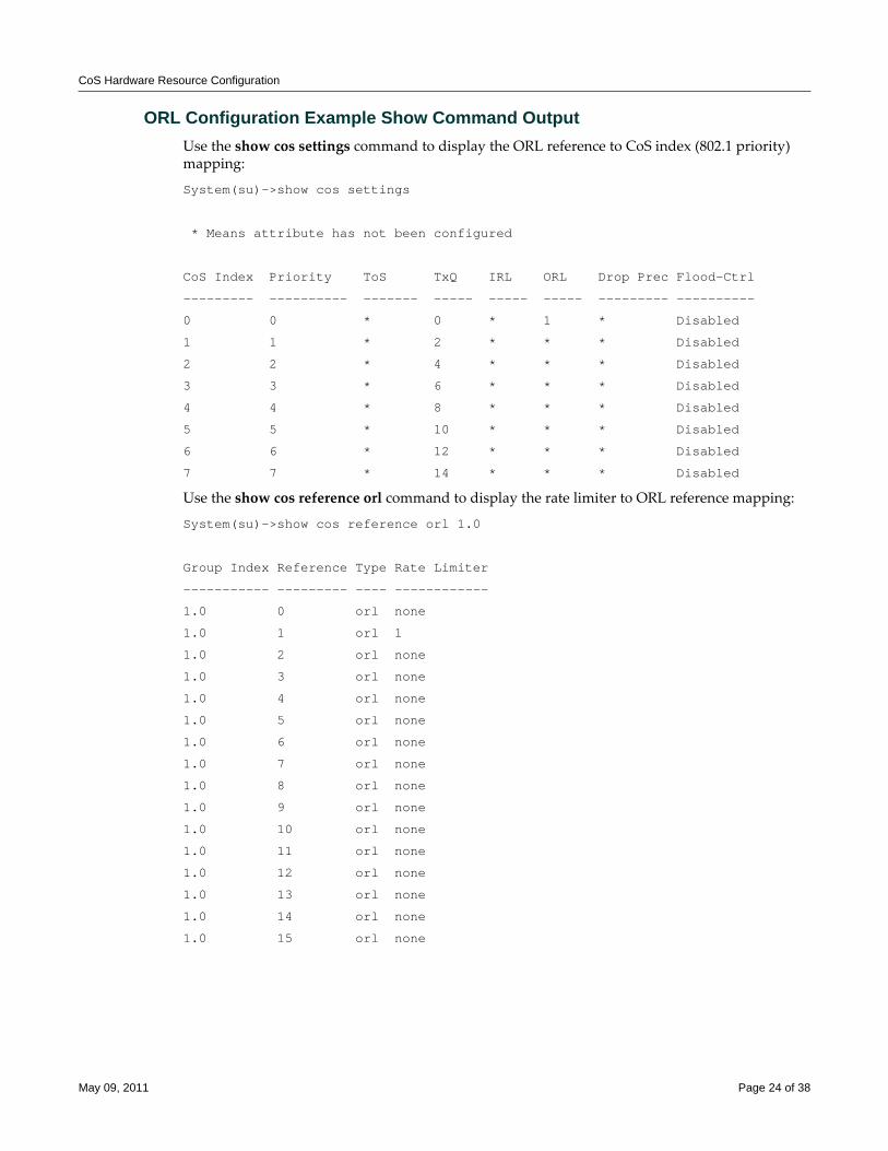
CoS Hardware Resource Configuration
ORL Configuration Example Show Command OutputUse the show cos settings command to display the ORL reference to CoS index (802.1 priority) mapping:
System(su)->show cos settings
* Means attribute has not been configured
CoS Index Priority ToS TxQ IRL ORL Drop Prec Flood-Ctrl
--------- ---------- ------- ----- ----- ----- --------- ----------
0 0 * 0 * 1 * Disabled
1 1 * 2 * * * Disabled
2 2 * 4 * * * Disabled
3 3 * 6 * * * Disabled
4 4 * 8 * * * Disabled
5 5 * 10 * * * Disabled
6 6 * 12 * * * Disabled
7 7 * 14 * * * Disabled
Use the show cos reference orl command to display the rate limiter to ORL reference mapping:
System(su)->show cos reference orl 1.0
Group Index Reference Type Rate Limiter
----------- --------- ---- ------------
1.0 0 orl none
1.0 1 orl 1
1.0 2 orl none
1.0 3 orl none
1.0 4 orl none
1.0 5 orl none
1.0 6 orl none
1.0 7 orl none
1.0 8 orl none
1.0 9 orl none
1.0 10 orl none
1.0 11 orl none
1.0 12 orl none
1.0 13 orl none
1.0 14 orl none
1.0 15 orl none
May 09, 2011 Page 24 of 38
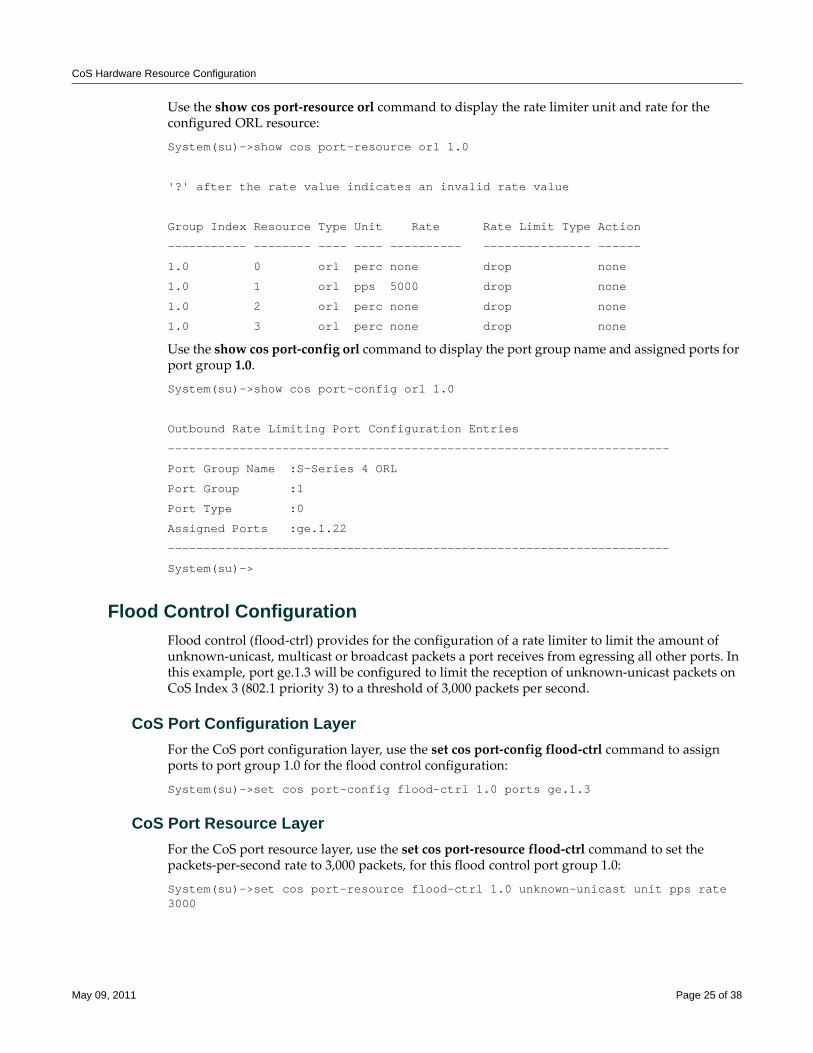
CoS Hardware Resource Configuration
Use the show cos port‐resource orl command to display the rate limiter unit and rate for the configured ORL resource:
System(su)->show cos port-resource orl 1.0
'?' after the rate value indicates an invalid rate value
Group Index Resource Type Unit Rate Rate Limit Type Action
----------- -------- ---- ---- ---------- --------------- ------
1.0 0 orl perc none drop none
1.0 1 orl pps 5000 drop none
1.0 2 orl perc none drop none
1.0 3 orl perc none drop none
Use the show cos port‐config orl command to display the port group name and assigned ports for port group 1.0.
System(su)->show cos port-config orl 1.0
Outbound Rate Limiting Port Configuration Entries
----------------------------------------------------------------------
Port Group Name :S-Series 4 ORL
Port Group :1
Port Type :0
Assigned Ports :ge.1.22
----------------------------------------------------------------------
System(su)->
Flood Control ConfigurationFlood control (flood‐ctrl) provides for the configuration of a rate limiter to limit the amount of unknown‐unicast, multicast or broadcast packets a port receives from egressing all other ports. In this example, port ge.1.3 will be configured to limit the reception of unknown‐unicast packets on CoS Index 3 (802.1 priority 3) to a threshold of 3,000 packets per second.
CoS Port Configuration LayerFor the CoS port configuration layer, use the set cos port‐config flood‐ctrl command to assign ports to port group 1.0 for the flood control configuration:
System(su)->set cos port-config flood-ctrl 1.0 ports ge.1.3
CoS Port Resource LayerFor the CoS port resource layer, use the set cos port‐resource flood‐ctrl command to set the packets‐per‐second rate to 3,000 packets, for this flood control port group 1.0:
System(su)->set cos port-resource flood-ctrl 1.0 unknown-unicast unit pps rate 3000
May 09, 2011 Page 25 of 38
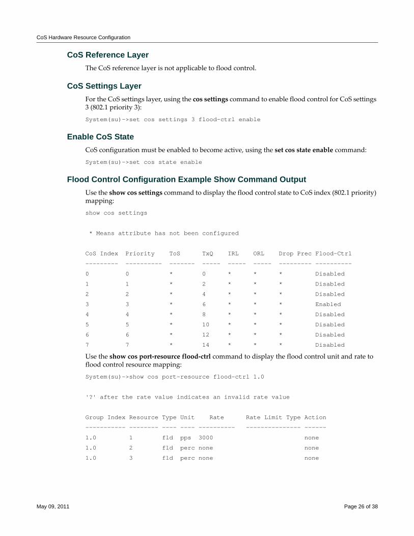
CoS Hardware Resource Configuration
CoS Reference LayerThe CoS reference layer is not applicable to flood control.
CoS Settings LayerFor the CoS settings layer, using the cos settings command to enable flood control for CoS settings 3 (802.1 priority 3):
System(su)->set cos settings 3 flood-ctrl enable
Enable CoS StateCoS configuration must be enabled to become active, using the set cos state enable command:
System(su)->set cos state enable
Flood Control Configuration Example Show Command OutputUse the show cos settings command to display the flood control state to CoS index (802.1 priority) mapping:
show cos settings
* Means attribute has not been configured
CoS Index Priority ToS TxQ IRL ORL Drop Prec Flood-Ctrl
--------- ---------- ------- ----- ----- ----- --------- ----------
0 0 * 0 * * * Disabled
1 1 * 2 * * * Disabled
2 2 * 4 * * * Disabled
3 3 * 6 * * * Enabled
4 4 * 8 * * * Disabled
5 5 * 10 * * * Disabled
6 6 * 12 * * * Disabled
7 7 * 14 * * * Disabled
Use the show cos port‐resource flood‐ctrl command to display the flood control unit and rate to flood control resource mapping:
System(su)->show cos port-resource flood-ctrl 1.0
'?' after the rate value indicates an invalid rate value
Group Index Resource Type Unit Rate Rate Limit Type Action
----------- -------- ---- ---- ---------- --------------- ------
1.0 1 fld pps 3000 none
1.0 2 fld perc none none
1.0 3 fld perc none none
May 09, 2011 Page 26 of 38
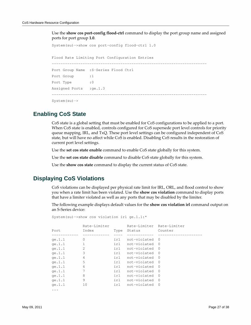
CoS Hardware Resource Configuration
Use the show cos port‐config flood‐ctrl command to display the port group name and assigned ports for port group 1.0.
System(su)->show cos port-config flood-ctrl 1.0
Flood Rate Limiting Port Configuration Entries
----------------------------------------------------------------------
Port Group Name :S-Series Flood Ctrl
Port Group :1
Port Type :0
Assigned Ports :ge.1.3
----------------------------------------------------------------------
System(su)->
Enabling CoS StateCoS state is a global setting that must be enabled for CoS configurations to be applied to a port. When CoS state is enabled, controls configured for CoS supersede port level controls for priority queue mapping, IRL, and TxQ. These port level settings can be configured independent of CoS state, but will have no affect while CoS is enabled. Disabling CoS results in the restoration of current port level settings.
Use the set cos state enable command to enable CoS state globally for this system.
Use the set cos state disable command to disable CoS state globally for this system.
Use the show cos state command to display the current status of CoS state.
Displaying CoS ViolationsCoS violations can be displayed per physical rate limit for IRL, ORL, and flood control to show you when a rate limit has been violated. Use the show cos violation command to display ports that have a limiter violated as well as any ports that may be disabled by the limiter.
The following example displays default values for the show cos violation irl command output on an S‐Series device:
System(su)->show cos violation irl ge.1.1:*
Rate-Limiter Rate-Limiter Rate-LimiterPort Index Type Status Counter------------ ------------ ---- ------------ --------------------ge.1.1 0 irl not-violated 0ge.1.1 1 irl not-violated 0ge.1.1 2 irl not-violated 0ge.1.1 3 irl not-violated 0ge.1.1 4 irl not-violated 0ge.1.1 5 irl not-violated 0ge.1.1 6 irl not-violated 0ge.1.1 7 irl not-violated 0ge.1.1 8 irl not-violated 0ge.1.1 9 irl not-violated 0ge.1.1 10 irl not-violated 0...
May 09, 2011 Page 27 of 38
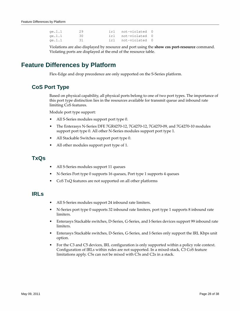
Feature Differences by Platform
ge.1.1 29 irl not-violated 0ge.1.1 30 irl not-violated 0ge.1.1 31 irl not-violated 0
Violations are also displayed by resource and port using the show cos port‐resource command. Violating ports are displayed at the end of the resource table.
Feature Differences by PlatformFlex‐Edge and drop precedence are only supported on the S‐Series platform.
CoS Port Type Based on physical capability, all physical ports belong to one of two port types. The importance of this port type distinction lies in the resources available for transmit queue and inbound rate limiting CoS features.
Module port type support:
• All S‐Series modules support port type 0.
• The Enterasys N‐Series DFE 7GR4270‐12, 7G4270‐12, 7G4270‐09, and 7G4270‐10 modules support port type 0. All other N‐Series modules support port type 1.
• All Stackable Switches support port type 0.
• All other modules support port type of 1.
TxQs• All S‐Series modules support 11 queues
• N‐Series Port type 0 supports 16 queues, Port type 1 supports 4 queues
• CoS TxQ features are not supported on all other platforms
IRLs• All S‐Series modules support 24 inbound rate limiters.
• N‐Series port type 0 supports 32 inbound rate limiters, port type 1 supports 8 inbound rate limiters.
• Enterasys Stackable switches, D‐Series, G‐Series, and I‐Series devices support 99 inbound rate limiters.
• Enterasys Stackable switches, D‐Series, G‐Series, and I‐Series only support the IRL Kbps unit option.
• For the C3 and C5 devices, IRL configuration is only supported within a policy role context. Configuration of IRLs within rules are not supported. In a mixed‐stack, C3 CoS feature limitations apply. C5s can not be mixed with C3s and C2s in a stack.
May 09, 2011 Page 28 of 38
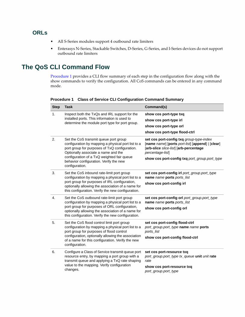
ORLs• All S‐Series modules support 4 outbound rate limiters
• Enterasys N‐Series, Stackable Switches, D‐Series, G‐Series, and I‐Series devices do not support outbound rate limiters
The QoS CLI Command FlowProcedure 1 provides a CLI flow summary of each step in the configuration flow along with the show commands to verify the configuration. All CoS commands can be entered in any command mode.
Procedure 1 Class of Service CLI Configuration Command Summary
Step Task Command(s)
1. Inspect both the TxQs and IRL support for the installed ports. This information is used to determine the module port type for port group.
show cos port-type txqshow cos port-type irlshow cos port-type orlshow cos port-type flood-ctrl
2. Set the CoS transmit queue port group configuration by mapping a physical port list to a port group for purposes of TxQ configuration. Optionally associate a name and the configuration of a TxQ weighted fair queue behavior configuration. Verify the new configuration.
set cos port-config txq group-type-index [name name] [ports port-list] [append] | [clear] [arb-slice slice-list] [arb-percentage percentage-list]
show cos port-config txq port_group.port_type
3. Set the CoS inbound rate-limit port group configuration by mapping a physical port list to a port group for purposes of IRL configuration, optionally allowing the association of a name for this configuration. Verify the new configuration.
set cos port-config irl port_group.port_type name name ports ports_list
show cos port-config irl
4. Set the CoS outbound rate-limit port group configuration by mapping a physical port list to a port group for purposes of ORL configuration, optionally allowing the association of a name for this configuration. Verify the new configuration.
set cos port-config orl port_group.port_type name name ports ports_list
show cos port-config orl
5. Set the CoS flood control limit port group configuration by mapping a physical port list to a port group for purposes of flood control configuration, optionally allowing the association of a name for this configuration. Verify the new configuration.
set cos port-config flood-ctrl port_group.port_type name name ports ports_list
show cos port-config flood-ctrl
6. Configure a Class of Service transmit queue port resource entry, by mapping a port group with a transmit queue and applying a TxQ rate shaping value to the mapping. Verify configuration changes.
set cos port-resource txq port_group.port_type tx_queue unit unit rate rate
show cos port-resource txq port_group.port_type
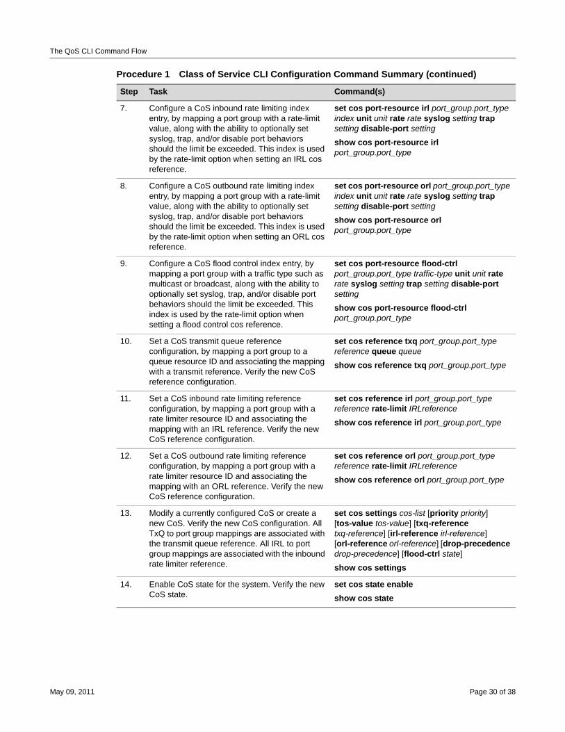
The QoS CLI Command Flow
7. Configure a CoS inbound rate limiting index entry, by mapping a port group with a rate-limit value, along with the ability to optionally set syslog, trap, and/or disable port behaviors should the limit be exceeded. This index is used by the rate-limit option when setting an IRL cos reference.
set cos port-resource irl port_group.port_type index unit unit rate rate syslog setting trap setting disable-port setting
show cos port-resource irl port_group.port_type
8. Configure a CoS outbound rate limiting index entry, by mapping a port group with a rate-limit value, along with the ability to optionally set syslog, trap, and/or disable port behaviors should the limit be exceeded. This index is used by the rate-limit option when setting an ORL cos reference.
set cos port-resource orl port_group.port_type index unit unit rate rate syslog setting trap setting disable-port setting
show cos port-resource orl port_group.port_type
9. Configure a CoS flood control index entry, by mapping a port group with a traffic type such as multicast or broadcast, along with the ability to optionally set syslog, trap, and/or disable port behaviors should the limit be exceeded. This index is used by the rate-limit option when setting a flood control cos reference.
set cos port-resource flood-ctrl port_group.port_type traffic-type unit unit rate rate syslog setting trap setting disable-port setting
show cos port-resource flood-ctrl port_group.port_type
10. Set a CoS transmit queue reference configuration, by mapping a port group to a queue resource ID and associating the mapping with a transmit reference. Verify the new CoS reference configuration.
set cos reference txq port_group.port_type reference queue queue
show cos reference txq port_group.port_type
11. Set a CoS inbound rate limiting reference configuration, by mapping a port group with a rate limiter resource ID and associating the mapping with an IRL reference. Verify the new CoS reference configuration.
set cos reference irl port_group.port_type reference rate-limit IRLreference
show cos reference irl port_group.port_type
12. Set a CoS outbound rate limiting reference configuration, by mapping a port group with a rate limiter resource ID and associating the mapping with an ORL reference. Verify the new CoS reference configuration.
set cos reference orl port_group.port_type reference rate-limit IRLreference
show cos reference orl port_group.port_type
13. Modify a currently configured CoS or create a new CoS. Verify the new CoS configuration. All TxQ to port group mappings are associated with the transmit queue reference. All IRL to port group mappings are associated with the inbound rate limiter reference.
set cos settings cos-list [priority priority] [tos-value tos-value] [txq-reference txq-reference] [irl-reference irl-reference] [orl-reference orl-reference] [drop-precedence drop-precedence] [flood-ctrl state]
show cos settings
14. Enable CoS state for the system. Verify the new CoS state.
set cos state enable
show cos state
Procedure 1 Class of Service CLI Configuration Command Summary (continued)
Step Task Command(s)
May 09, 2011 Page 30 of 38
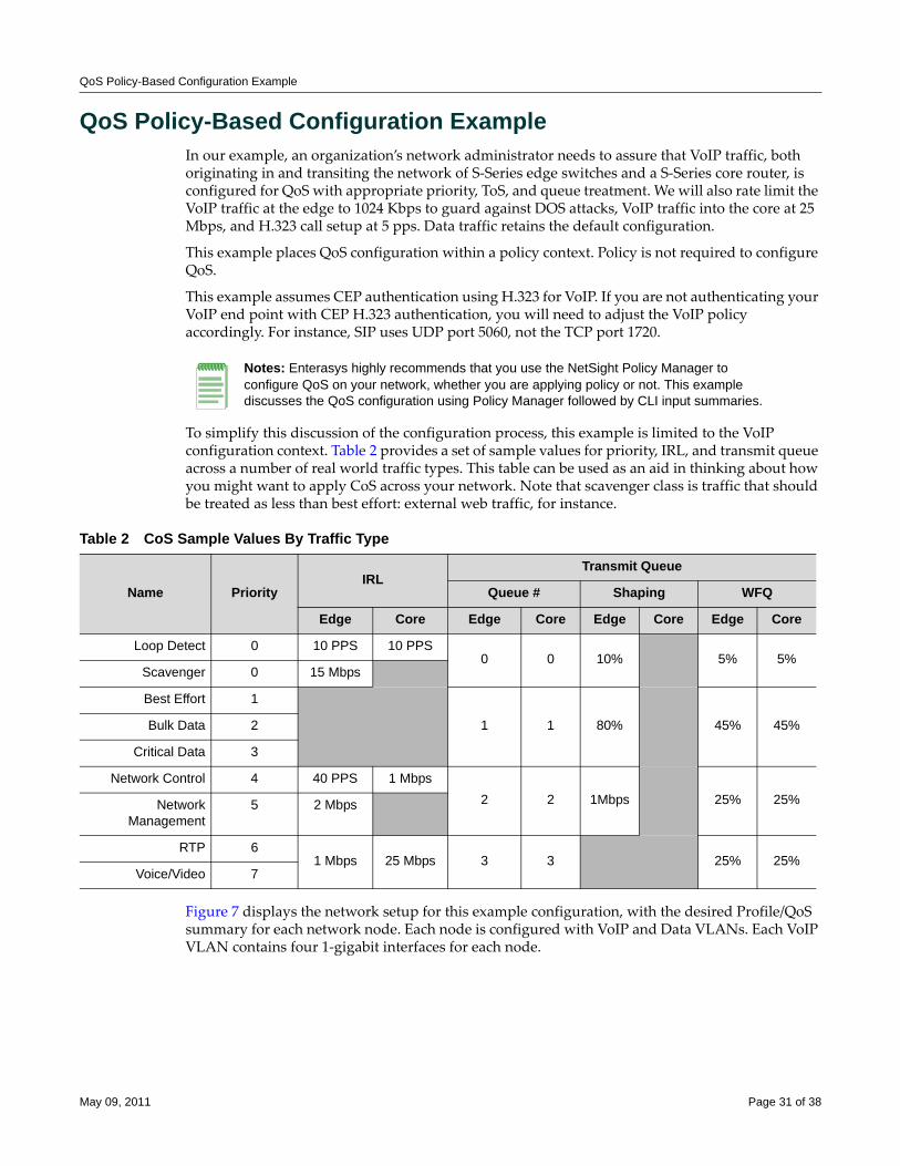
QoS Policy-Based Configuration Example
QoS Policy-Based Configuration ExampleIn our example, an organization’s network administrator needs to assure that VoIP traffic, both originating in and transiting the network of S‐Series edge switches and a S‐Series core router, is configured for QoS with appropriate priority, ToS, and queue treatment. We will also rate limit the VoIP traffic at the edge to 1024 Kbps to guard against DOS attacks, VoIP traffic into the core at 25 Mbps, and H.323 call setup at 5 pps. Data traffic retains the default configuration.
This example places QoS configuration within a policy context. Policy is not required to configure QoS.
This example assumes CEP authentication using H.323 for VoIP. If you are not authenticating your VoIP end point with CEP H.323 authentication, you will need to adjust the VoIP policy accordingly. For instance, SIP uses UDP port 5060, not the TCP port 1720.
To simplify this discussion of the configuration process, this example is limited to the VoIP configuration context. Table 2 provides a set of sample values for priority, IRL, and transmit queue across a number of real world traffic types. This table can be used as an aid in thinking about how you might want to apply CoS across your network. Note that scavenger class is traffic that should be treated as less than best effort: external web traffic, for instance.
Figure 7 displays the network setup for this example configuration, with the desired Profile/QoS summary for each network node. Each node is configured with VoIP and Data VLANs. Each VoIP VLAN contains four 1‐gigabit interfaces for each node.
Notes: Enterasys highly recommends that you use the NetSight Policy Manager to configure QoS on your network, whether you are applying policy or not. This example discusses the QoS configuration using Policy Manager followed by CLI input summaries.
Table 2 CoS Sample Values By Traffic Type
Name PriorityIRL
Transmit Queue
Queue # Shaping WFQ
Edge Core Edge Core Edge Core Edge Core
Loop Detect 0 10 PPS 10 PPS0 0 10% 5% 5%
Scavenger 0 15 Mbps
Best Effort 1
1 1 80% 45% 45%Bulk Data 2
Critical Data 3
Network Control 4 40 PPS 1 Mbps2 2 1Mbps 25% 25%Network
Management5 2 Mbps
RTP 61 Mbps 25 Mbps 3 3 25% 25%
Voice/Video 7
May 09, 2011 Page 31 of 38
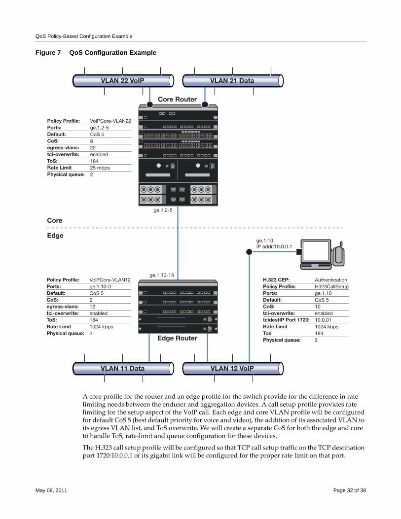
QoS Policy-Based Configuration Example
Figure 7 QoS Configuration Example
A core profile for the router and an edge profile for the switch provide for the difference in rate limiting needs between the enduser and aggregation devices. A call setup profile provides rate limiting for the setup aspect of the VoIP call. Each edge and core VLAN profile will be configured for default CoS 5 (best default priority for voice and video), the addition of its associated VLAN to its egress VLAN list, and ToS overwrite. We will create a separate CoS for both the edge and core to handle ToS, rate‐limit and queue configuration for these devices.
The H.323 call setup profile will be configured so that TCP call setup traffic on the TCP destination port 1720:10.0.0.1 of its gigabit link will be configured for the proper rate limit on that port.
Core Router
Edge Router
Core
Edge
VLAN 22 VoIP VLAN 21 Data
VLAN 11 Data VLAN 12 VoIP
Policy Profile:Ports:Default:CoS:egress-vlans:tci-overwrite:ToS:Rate LimitPhysical queue:
VolPCore-VLAN22ge.1.2-5CoS 5822enabled18425 mbps2
ge.1.2-5
ge.1.10-13
ge.1.10IP addr:10.0.0.1
Policy Profile:Ports:Default:CoS:egress-vlans:tci-overwrite:ToS:Rate LimitPhysical queue:
VolPCore-VLAN12ge.1.10-3CoS 5912enabled1841024 kbps2
H.323 CEP:Policy Profile:Ports:Default:CoS:tci-overwrite:tcidestIP Port 1720:Rate LimitTosPhysical queue:
AuthenticationH323CallSetupge.1.10CoS 510enabled10.0.011024 kbps1842
May 09, 2011 Page 32 of 38
QoS Policy-Based Configuration Example
Using NetSight Policy Manager, configure the policy roles and related services as follows:
Setting the VoIP Core Policy Profile (Router 1)For S‐Series router 1, we configure a separate policy for VoIP Core. VoIP Core policy deals with packets transiting the core network using VoIP VLAN 22. For role VoIPCore we will:
• Configure VoIPEdge‐VLAN22 as the name of the role.
• Set default CoS to 5.
• Set the default access control to VLAN 22.
• Enable TCI overwrite so that ToS will be rewritten for this policy.
Create a Policy Service• Name the service VoIPCore Service.
• Apply the service to the VoIPCore Policy Role.
Create a Rate-limiterCreate a rate‐limit as follows:
• Inbound rate‐limit of 25 mbps
• Apply it to port group types 32/8/100 for index 0
Create Class of Service for VoIPEdge PolicyCreate CoS 8 as follows:
• 802.1p priority: 5
• ToS: B8
• Specify IRL index 0 to associate this CoS to the rate limit
Create a Rule• Create a Layer 2 traffic classification rule for VLAN ID 22 within the VoIPCore service.
• Associate CoS 8 as the action for the rule.
Setting the VoIP Edge Policy Profile (Switch 1)For S‐Series Switch 1, we configure a separate policy for VoIP edge. VoIP edge policy deals with packets transiting the edge network using VoIP VLAN 12 with edge access. For role VoIPEdge we will:
• Configure VoIPEdge‐VLAN12 as the name of the role.
• Set default CoS to 5.
• Set the default access control to VLAN 22.
• Enable TCI overwrite so that ToS will be rewritten for this policy.
May 09, 2011 Page 33 of 38
Create a Policy Service• Name the service VoIPEdge Service.
• Apply the service to the VoIPEdge Policy Role.
Create a Rate-limiterCreate a rate‐limit as follows:
• Inbound rate‐limit of 1 mbps
• Apply it to port group types 32/8/100 for index 0
Create Class of Service for VoIPEdge PolicyCreate CoS 9 as follows:
• 802.1p priority: 5
• ToS: B8
• Specify IRL index 0 to associate this CoS to the rate limit
Create a Rule• Create a Layer 2 traffic classification rule for VLAN ID 22 within the VoIPEdge service.
• Associate CoS 9 as the action for the rule.
Setting the H.323 Call Setup Policy ProfileH.323 Call Setup policy deals with the call setup traffic for VoIP H.323 authenticated users directly attached to Switch 1 using link ge.1.10. For role H.323 Call Setup we will:
• Configure H323CallSetup as the name of the role.
• Set default CoS to 5.
• Enable TCI overwrite so that ToS will be rewritten for this policy.
Create a Policy Service• Name the service H323CallSetup Service.
• Apply the service to the H323CallSetup Policy Role.
Create a Rate-limiterCreate a rate‐limit as follows:
• Inbound rate‐limit of 5 pps
• Apply it to port group types 32/8/100 for index 1
Create Class of Service for H323CallSetup PolicyCreate CoS 10 as follows:
• 802.1p priority: 5
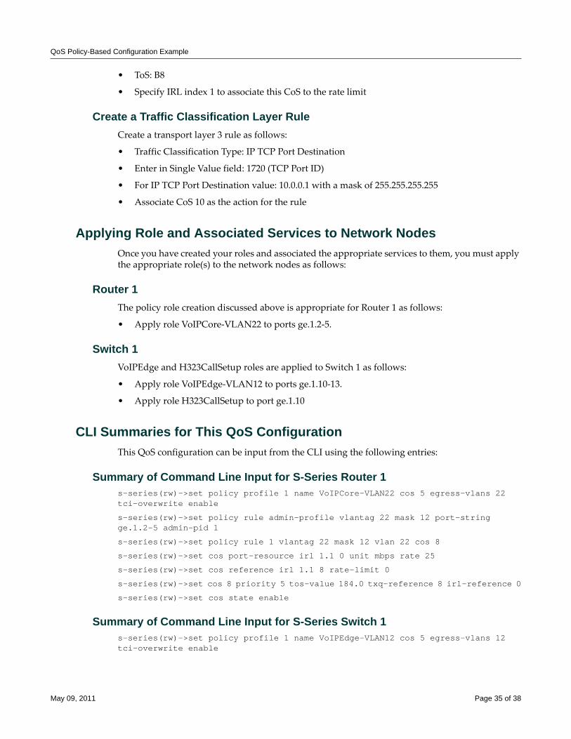
QoS Policy-Based Configuration Example
• ToS: B8
• Specify IRL index 1 to associate this CoS to the rate limit
Create a Traffic Classification Layer RuleCreate a transport layer 3 rule as follows:
• Traffic Classification Type: IP TCP Port Destination
• Enter in Single Value field: 1720 (TCP Port ID)
• For IP TCP Port Destination value: 10.0.0.1 with a mask of 255.255.255.255
• Associate CoS 10 as the action for the rule
Applying Role and Associated Services to Network NodesOnce you have created your roles and associated the appropriate services to them, you must apply the appropriate role(s) to the network nodes as follows:
Router 1The policy role creation discussed above is appropriate for Router 1 as follows:
• Apply role VoIPCore‐VLAN22 to ports ge.1.2‐5.
Switch 1VoIPEdge and H323CallSetup roles are applied to Switch 1 as follows:
• Apply role VoIPEdge‐VLAN12 to ports ge.1.10‐13.
• Apply role H323CallSetup to port ge.1.10
CLI Summaries for This QoS ConfigurationThis QoS configuration can be input from the CLI using the following entries:
Summary of Command Line Input for S-Series Router 1s-series(rw)->set policy profile 1 name VoIPCore-VLAN22 cos 5 egress-vlans 22 tci-overwrite enable
s-series(rw)->set policy rule admin-profile vlantag 22 mask 12 port-string ge.1.2-5 admin-pid 1
s-series(rw)->set policy rule 1 vlantag 22 mask 12 vlan 22 cos 8
s-series(rw)->set cos port-resource irl 1.1 0 unit mbps rate 25
s-series(rw)->set cos reference irl 1.1 8 rate-limit 0
s-series(rw)->set cos 8 priority 5 tos-value 184.0 txq-reference 8 irl-reference 0
s-series(rw)->set cos state enable
Summary of Command Line Input for S-Series Switch 1s-series(rw)->set policy profile 1 name VoIPEdge-VLAN12 cos 5 egress-vlans 12 tci-overwrite enable
May 09, 2011 Page 35 of 38
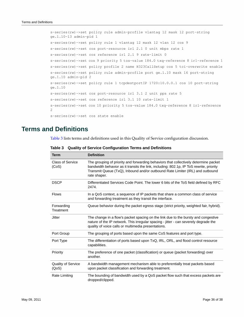
Terms and Definitions
s-series(rw)->set policy rule admin-profile vlantag 12 mask 12 port-string ge.1.10-13 admin-pid 1
s-series(rw)->set policy rule 1 vlantag 12 mask 12 vlan 12 cos 9
s-series(rw)->set cos port-resource irl 2.1 0 unit mbps rate 1
s-series(rw)->set cos reference irl 2.1 9 rate-limit 0
s-series(rw)->set cos 9 priority 5 tos-value 184.0 txq-reference 8 irl-reference 1
s-series(rw)->set policy profile 2 name H323CallSetup cos 5 tci-overwrite enable
s-series(rw)->set policy rule admin-profile port ge.1.10 mask 16 port-string ge.1.10 admin-pid 2
s-series(rw)->set policy rule 1 tcpdestportIP 1720:10.0.0.1 cos 10 port-string ge.1.10
s-series(rw)->set cos port-resource irl 3.1 2 unit pps rate 5
s-series(rw)->set cos reference irl 3.1 10 rate-limit 1
s-series(rw)->set cos 10 priority 5 tos-value 184.0 txq-reference 8 irl-reference 2
s-series(rw)->set cos state enable
Terms and DefinitionsTable 3 lists terms and definitions used in this Quality of Service configuration discussion.
Table 3 Quality of Service Configuration Terms and Definitions Term Definition
Class of Service (CoS)
The grouping of priority and forwarding behaviors that collectively determine packet bandwidth behavior as it transits the link, including: 802.1p, IP ToS rewrite, priority Transmit Queue (TxQ), Inbound and/or outbound Rate Limiter (IRL) and outbound rate shaper.
DSCP Differentiated Services Code Point. The lower 6 bits of the ToS field defined by RFC 2474.
Flows In a QoS context, a sequence of IP packets that share a common class of service and forwarding treatment as they transit the interface.
Forwarding Treatment
Queue behavior during the packet egress stage (strict priority, weighted fair, hybrid).
Jitter The change in a flow’s packet spacing on the link due to the bursty and congestive nature of the IP network. This irregular spacing - jitter - can severely degrade the quality of voice calls or multimedia presentations.
Port Group The grouping of ports based upon the same CoS features and port type.
Port Type The differentiation of ports based upon TxQ, IRL, ORL, and flood control resource capabilities.
Priority The preference of one packet (classification) or queue (packet forwarding) over another.
Quality of Service (QoS)
A bandwidth management mechanism able to preferentially treat packets based upon packet classification and forwarding treatment.
Rate Limiting The bounding of bandwidth used by a QoS packet flow such that excess packets are dropped/clipped.
May 09, 2011 Page 36 of 38

Terms and Definitions
Rate Shaping The rescheduling of bursty traffic while in the queue based upon packet buffering such that traffic beyond the configured bandwidth threshold is delayed until bandwidth usage falls below the configured threshold.
Type of Service (ToS)
An 8-bit field defined by RFC 1349 used for the prioritization of packets within a QoS context.
Table 3 Quality of Service Configuration Terms and Definitions (continued)Term Definition
May 09, 2011 Page 37 of 38

Enterasys Networks reserves the right to make changes in specifications and other information contained in this document and its web site without prior notice. The reader should in all cases consult Enterasys Networks to determine whether any such changes have been made.
The hardware, firmware, or software described in this document is subject to change without notice.
IN NO EVENT SHALL ENTERASYS NETWORKS BE LIABLE FOR ANY INCIDENTAL, INDIRECT, SPECIAL, OR CONSEQUENTIAL DAMAGES WHATSOEVER (INCLUDING BUT NOT LIMITED TO LOST PROFITS) ARISING OUT OF OR RELATED TO THIS DOCUMENT, WEB SITE, OR THE INFORMATION CONTAINED IN THEM, EVEN IF ENTERASYS NETWORKS HAS BEEN ADVISED OF, KNEW OF, OR SHOULD HAVE KNOWN OF, THE POSSIBILITY OF SUCH DAMAGES.
Enterasys Networks, Inc.50 Minuteman RoadAndover, MA 01810
© 2011 Enterasys Networks, Inc. All rights reserved.
ENTERASYS, ENTERASYS NETWORKS, ENTERASYS NETSIGHT, LANVIEW, WEBVIEW, S‐SERIES and any logos associated therewith, are trademarks or registered trademarks of Enterasys Networks, Inc., in the United States and other countries. For a complete list of Enterasys trademarks, see http://www.enterasys.com/company/trademarks.aspx.
All other product names mentioned in this manual may be trademarks or registered trademarks of their respective companies.
Revision History
Date Description
January 28,2008 Initial Release of the Document
February 22, 2008 Modifications due to product branding changes.
September 18, 2008 Modifications due to product branding changes and minor template updates.
January 23, 2009 Cosmetic changes only.
May 09, 2011 Updated for S-Series, IRL, ORL, flood control, and Flex-Edge features, plus major rewrite of overview information.
Configuring RADIUS-Snooping
This chapter provides the following information about configuring and monitoring RADIUS‐Snooping on Enterasys® N‐Series, S‐Series®, and K‐Series modular switches.
What is RADIUS-Snooping?RADIUS‐Snooping (RS) is one of the Enterasys® MultiAuth suite of authentication methods. See the Configuring Authentication Feature Guide for a detailed discussion of the other authentication methods supported by Enterasys modular switches. RS resides on the distribution‐tier switch, allowing for management of any directly connected edge switch that uses the RADIUS protocol to authenticate a network end‐station, but does not support the full complement of the Enterasys® Secure Networks™ capabilities.
The RADIUS client edge‐switch initiates an authentication request, by sending a RADIUS request to the RADIUS server that resides upstream of the distribution‐tier switch. By investigating the RADIUS request frames, RS can determine the MAC address of the end‐user device being authenticated. The network administrator creates a user account on the RADIUS server for the end‐user that includes any policy, dynamic VLAN assignment, and other RADIUS and RS attributes for this end‐station. By investigating the RADIUS response from the RADIUS server, RS can build a MutiAuth session as though the end‐user were directly connected to the distribution‐tier device.
Sessions detected by RS function identically to local authenticated sessions from the perspective of the Enterasys MultiAuth framework, with the exception that RS can not force a reauthentication event; it can only timeout the session.
For information about... Refer to page...
What is RADIUS-Snooping? 1
Why Would I Use RADIUS-Snooping in My Network? 2
How Can I Implement RADIUS-Snooping? 2
RADIUS-Snooping Overview 2
Configuring RADIUS-Snooping 6
RADIUS-Snooping Configuration Example 8
Terms and Definitions 10
June 03, 2011 Page 1 of 12
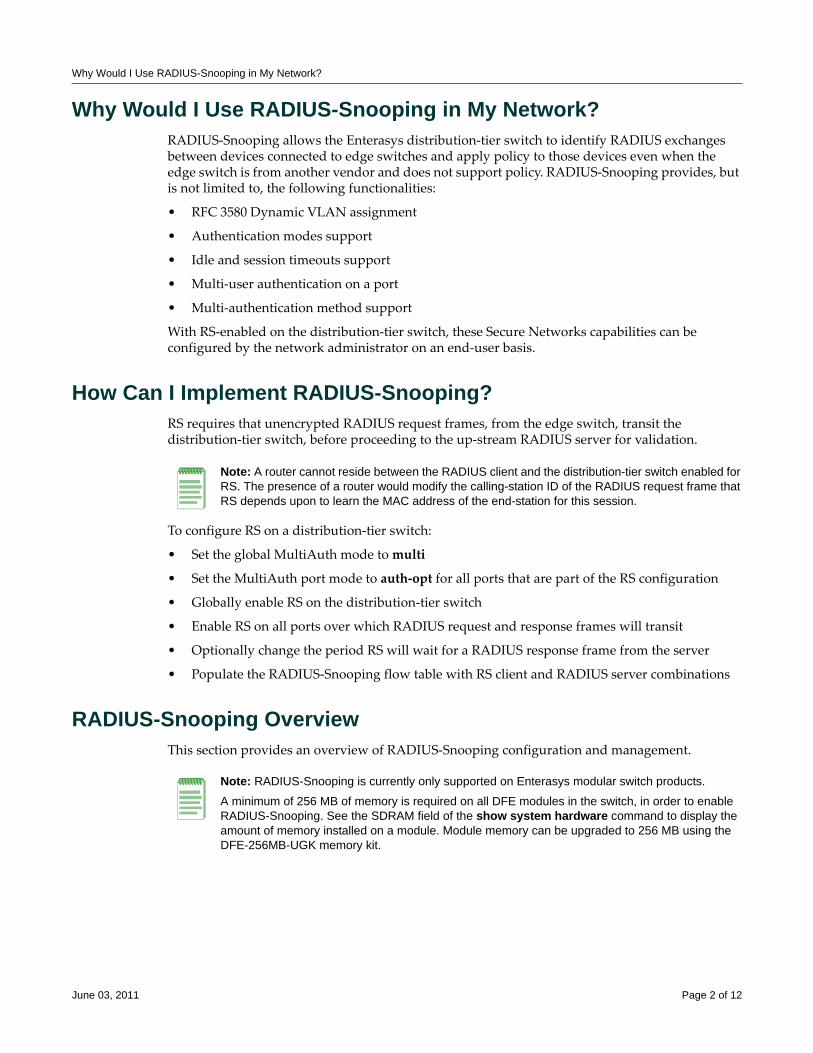
Why Would I Use RADIUS-Snooping in My Network?
Why Would I Use RADIUS-Snooping in My Network?RADIUS‐Snooping allows the Enterasys distribution‐tier switch to identify RADIUS exchanges between devices connected to edge switches and apply policy to those devices even when the edge switch is from another vendor and does not support policy. RADIUS‐Snooping provides, but is not limited to, the following functionalities:
• RFC 3580 Dynamic VLAN assignment
• Authentication modes support
• Idle and session timeouts support
• Multi‐user authentication on a port
• Multi‐authentication method support
With RS‐enabled on the distribution‐tier switch, these Secure Networks capabilities can be configured by the network administrator on an end‐user basis.
How Can I Implement RADIUS-Snooping?RS requires that unencrypted RADIUS request frames, from the edge switch, transit the distribution‐tier switch, before proceeding to the up‐stream RADIUS server for validation.
To configure RS on a distribution‐tier switch:
• Set the global MultiAuth mode to multi
• Set the MultiAuth port mode to auth‐opt for all ports that are part of the RS configuration
• Globally enable RS on the distribution‐tier switch
• Enable RS on all ports over which RADIUS request and response frames will transit
• Optionally change the period RS will wait for a RADIUS response frame from the server
• Populate the RADIUS‐Snooping flow table with RS client and RADIUS server combinations
RADIUS-Snooping OverviewThis section provides an overview of RADIUS‐Snooping configuration and management.
Note: A router cannot reside between the RADIUS client and the distribution-tier switch enabled for RS. The presence of a router would modify the calling-station ID of the RADIUS request frame that RS depends upon to learn the MAC address of the end-station for this session.
Note: RADIUS-Snooping is currently only supported on Enterasys modular switch products.
A minimum of 256 MB of memory is required on all DFE modules in the switch, in order to enable RADIUS-Snooping. See the SDRAM field of the show system hardware command to display the amount of memory installed on a module. Module memory can be upgraded to 256 MB using the DFE-256MB-UGK memory kit.
June 03, 2011 Page 2 of 12
RADIUS-Snooping Overview
RADIUS-Snooping Configuration
MultiAuth ConfigurationMultiAuth must be enabled if the RADIUS‐Snooping configuration involves the authentication of more than a single user on a port. There are two aspects to multiauthentication in a RADIUS‐Snooping configuration:
• The global MultiAuth mode must be changed from the default mode of strict to multi, in order to authenticate multiple downstream users.
• The MultiAuth port mode must be set to auth‐opt for both upstream (to the RADIUS server) and downstream (to the authenticating switch) ports. Setting global MultiAuth to multi sets the default port value from auth‐opt to force‐auth. Reset the mode for the affected ports to auth‐opt.
See the Configuring User Authentication feature guide at https://extranet.enterasys.com/downloads/ for a complete discussion on MultiAuth configuration.
Enabling RADIUS-SnoopingRS is enabled globally on the distribution‐tier switch. It is also enabled on the distribution‐tier switch ports directly attached to the edge switch that the RADIUS request frames transit, from the edge switch to the RADIUS server, as well as the ports the response frames transit, from the RADIUS server back to the edge switch.
Configuring Enabled Port SettingsThe number of seconds the firmware waits for a RADIUS response after it successfully snoops a RADIUS request can be set per‐port. If you do not set this timeout at the port level, the system level setting is used.
In some cases it may be necessary to drop RADIUS traffic between the distribution tier device and the edge switches. You can enable or disable packet drop on a per port basis. Packets are always dropped for a resource issue situation. RS is not capable of forcing a reauthentication event should it be unable to investigate a RADIUS request exchange. Dropping a RADIUS request packet due to resource exhaustion, in most cases, will cause the edge device to retry a RADIUS request, providing another opportunity to snoop the RADIUS exchange. Frames with an invalid format for the calling station ID are only dropped when drop is enabled. In the case of dropping frames with an invalid format, authentication will not take place for this end‐user.
The authallocated value specifies the maximum number of RS users per port. You can configure this number of allowed RS users on a per port basis. The default value depends upon the system license for this device. You should set this authallocated value equal to or less than the configured value for the set multiauth port numusers command. This value is the maximum number of users per port for all authentication clients. Typically, authallocated and multiauth port numusers are set to the same value.
Populating the RADIUS-Snooping Flow TableThe RADIUS‐Snooping flow table is a filter that determines which RADIUS server and client combinations will be snooped. If the secret is configured, the response frames are checked for valid MD5 checksum, in order to validate the sender.
The RS flow table contains RADIUS server and client entries for each RADIUS server and client combination for which RS will be used on this system. The RADIUS client IP address and authenticating RADIUS server IP address are manually entered into the RADIUS‐Snooping flow
June 03, 2011 Page 3 of 12
RADIUS-Snooping Overview
table. By default, the RADIUS‐Snooping flow table is empty. Entries are added to the flow table based upon an index entry. The first matching entry in the table is used for the continuation of the authentication process.
When an investigated RADIUS frame transits the RS‐enabled port with a match in the flow table, RS will track that RADIUS request and response exchange and will build a MultiAuth session for the end‐user, based upon what it finds in the RADIUS response frames.
Setting the RADIUS-Snooping TimeoutA timeout is configured to set the number of seconds that the firmware waits for a RADIUS response frame to be returned from the RADIUS server, after successfully snooping a RADIUS request frame from the client. If no response is seen before the timeout expires, the session is terminated.
RADIUS-Snooping ManagementRADIUS‐Snooping management options are available to:
• Terminate all RS sessions or on a per port or MAC address basis
• Reset all RS configuration to its default settings
• Clear all RADIUS‐Snooping flow table entries or per index entry
• Display RS statistics
RADIUS Session AttributesThe RADIUS attributes defining the session are returned in the RADIUS response frame. RADIUS attributes are used to configure the user on the system. Attributes explicitly supported by RS that may be included in the RADIUS response frame are:
• Idle‐Timeout – If no frames are seen from this MAC address, for the number of seconds configured, the session will be terminated.
• Session‐Timeout – The session is terminated after the number of seconds configured.
• Filter‐ID – Defines the policy profile (role) and CLI management privilege level, just as it would for any other local authentication agent.
• Tunnel‐Group‐Id – Specifies the VLAN ID for this session.
Note: Numerous attributes may be supported by the RADIUS client for general RADIUS protocol support. Such attributes are beyond the scope of this document. This RS implementation does not interfere with normal RADIUS client attribute support. The list above indicates attributes actually used by this RADIUS-Snooping application once authentication is successfully completed.
June 03, 2011 Page 4 of 12
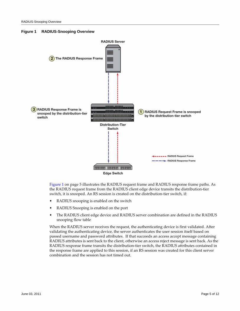
RADIUS-Snooping Overview
Figure 1 RADIUS-Snooping Overview
Figure 1 on page 5 illustrates the RADIUS request frame and RADIUS response frame paths. As the RADIUS request frame from the RADIUS client edge device transits the distribution‐tier switch, it is snooped. An RS session is created on the distribution‐tier switch, if:
• RADIUS snooping is enabled on the switch
• RADIUS Snooping is enabled on the port
• The RADIUS client edge device and RADIUS server combination are defined in the RADIUS snooping flow table
When the RADIUS server receives the request, the authenticating device is first validated. After validating the authenticating device, the server authenticates the user session itself based on passed username and password attributes. If that succeeds an access accept message containing RADIUS attributes is sent back to the client, otherwise an access reject message is sent back. As the RADIUS response frame transits the distribution‐tier switch, the RADIUS attributes contained in the response frame are applied to this session, if an RS session was created for this client server combination and the session has not timed out.
RADIUS Server
Distribution-TierSwitch
Edge Switch
The RADIUS Response Frame
13
2
RADIUS Request Frame is snoopedby the distribution-tier switch
RADIUS Request Frame
RADIUS Response Frame
RADIUS Response Frame issnooped by the distribution-tierswitch
June 03, 2011 Page 5 of 12
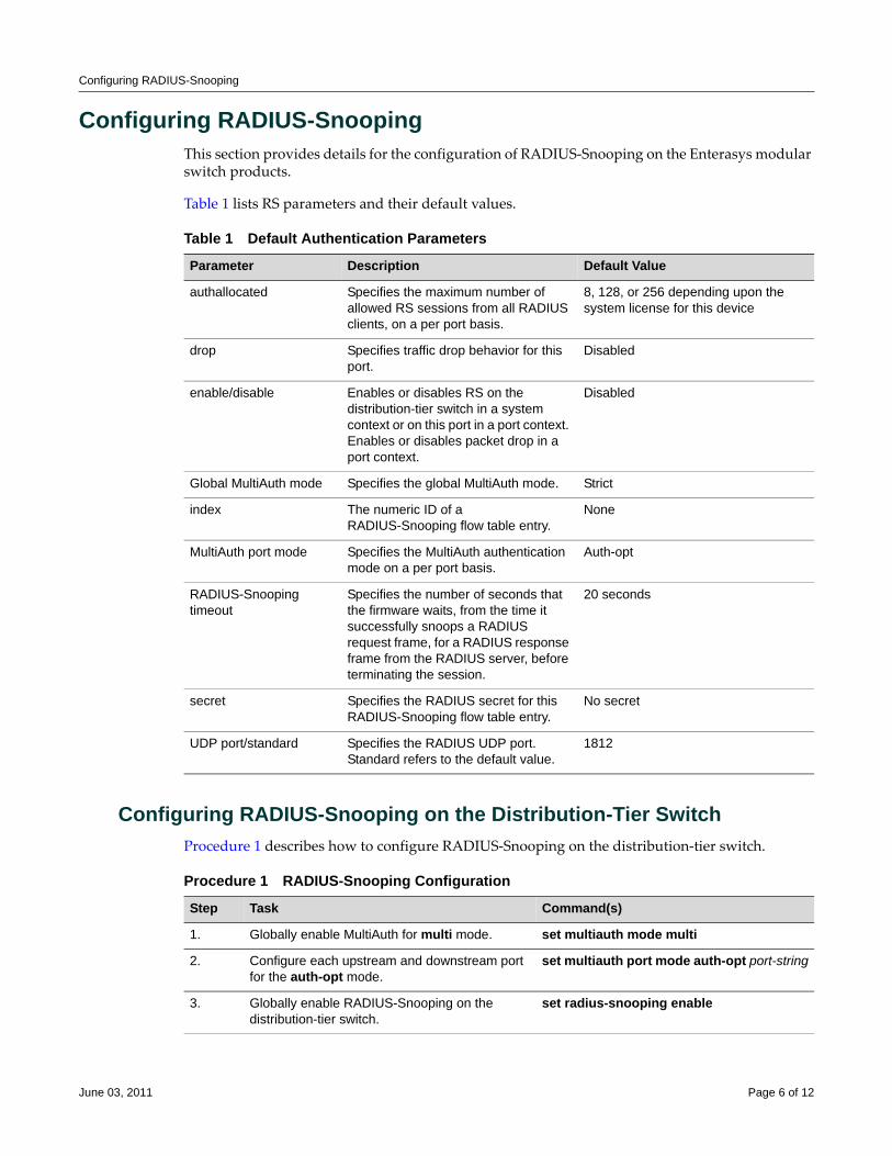
Configuring RADIUS-Snooping
Configuring RADIUS-SnoopingThis section provides details for the configuration of RADIUS‐Snooping on the Enterasys modular switch products.
Table 1 lists RS parameters and their default values.
Configuring RADIUS-Snooping on the Distribution-Tier SwitchProcedure 1 describes how to configure RADIUS‐Snooping on the distribution‐tier switch.
Table 1 Default Authentication Parameters
Parameter Description Default Value
authallocated Specifies the maximum number of allowed RS sessions from all RADIUS clients, on a per port basis.
8, 128, or 256 depending upon the system license for this device
drop Specifies traffic drop behavior for this port.
Disabled
enable/disable Enables or disables RS on the distribution-tier switch in a system context or on this port in a port context. Enables or disables packet drop in a port context.
Disabled
Global MultiAuth mode Specifies the global MultiAuth mode. Strict
index The numeric ID of a RADIUS-Snooping flow table entry.
None
MultiAuth port mode Specifies the MultiAuth authentication mode on a per port basis.
Auth-opt
RADIUS-Snooping timeout
Specifies the number of seconds that the firmware waits, from the time it successfully snoops a RADIUS request frame, for a RADIUS response frame from the RADIUS server, before terminating the session.
20 seconds
secret Specifies the RADIUS secret for this RADIUS-Snooping flow table entry.
No secret
UDP port/standard Specifies the RADIUS UDP port. Standard refers to the default value.
1812
Procedure 1 RADIUS-Snooping Configuration
Step Task Command(s)
1. Globally enable MultiAuth for multi mode. set multiauth mode multi
2. Configure each upstream and downstream port for the auth-opt mode.
set multiauth port mode auth-opt port-string
3. Globally enable RADIUS-Snooping on the distribution-tier switch.
set radius-snooping enable
June 03, 2011 Page 6 of 12
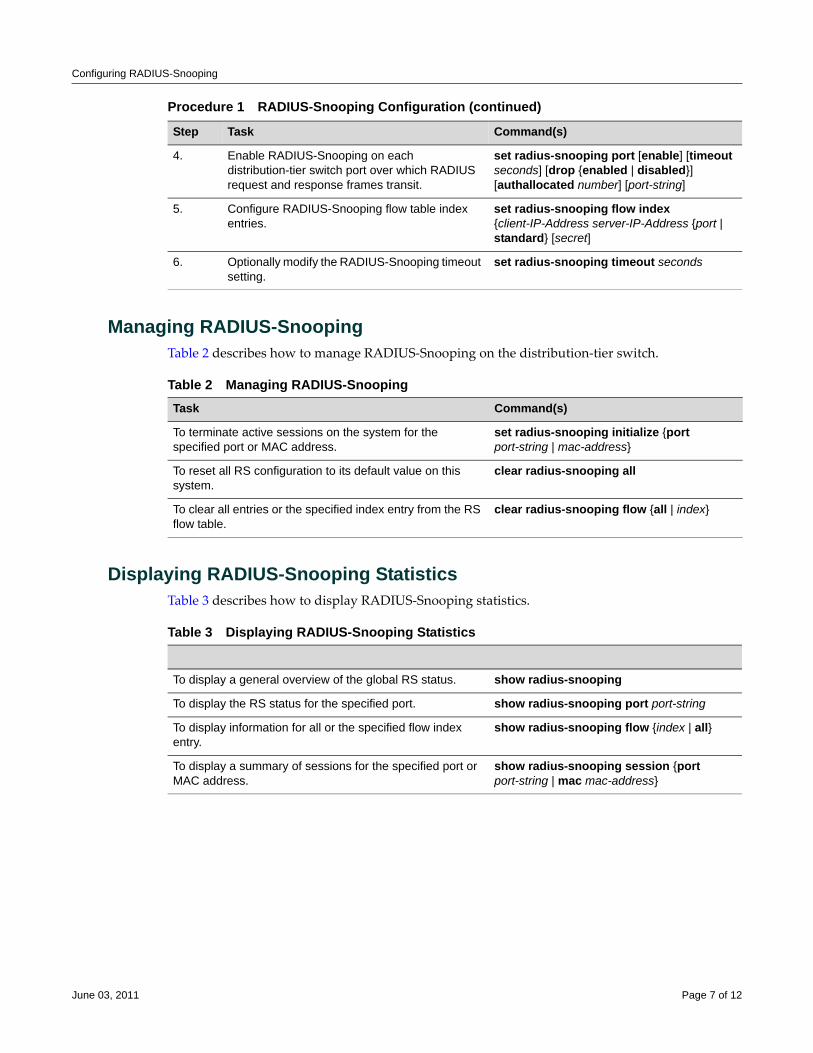
Configuring RADIUS-Snooping
Managing RADIUS-SnoopingTable 2 describes how to manage RADIUS‐Snooping on the distribution‐tier switch.
Displaying RADIUS-Snooping StatisticsTable 3 describes how to display RADIUS‐Snooping statistics.
4. Enable RADIUS-Snooping on each distribution-tier switch port over which RADIUS request and response frames transit.
set radius-snooping port [enable] [timeout seconds] [drop {enabled | disabled}] [authallocated number] [port-string]
5. Configure RADIUS-Snooping flow table index entries.
set radius-snooping flow index {client-IP-Address server-IP-Address {port | standard} [secret]
6. Optionally modify the RADIUS-Snooping timeout setting.
set radius-snooping timeout seconds
Procedure 1 RADIUS-Snooping Configuration (continued)
Step Task Command(s)
Table 2 Managing RADIUS-SnoopingTask Command(s)
To terminate active sessions on the system for the specified port or MAC address.
set radius-snooping initialize {port port-string | mac-address}
To reset all RS configuration to its default value on this system.
clear radius-snooping all
To clear all entries or the specified index entry from the RS flow table.
clear radius-snooping flow {all | index}
Table 3 Displaying RADIUS-Snooping Statistics
To display a general overview of the global RS status. show radius-snooping
To display the RS status for the specified port. show radius-snooping port port-string
To display information for all or the specified flow index entry.
show radius-snooping flow {index | all}
To display a summary of sessions for the specified port or MAC address.
show radius-snooping session {port port-string | mac mac-address}
June 03, 2011 Page 7 of 12
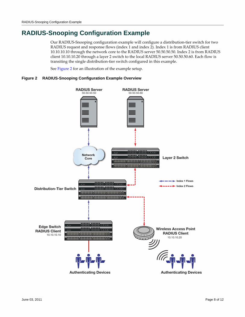
RADIUS-Snooping Configuration Example
RADIUS-Snooping Configuration ExampleOur RADIUS‐Snooping configuration example will configure a distribution‐tier switch for two RADIUS request and response flows (index 1 and index 2). Index 1 is from RADIUS client 10.10.10.10 through the network core to the RADIUS server 50.50.50.50. Index 2 is from RADIUS client 10.10.10.20 through a layer 2 switch to the local RADIUS server 50.50.50.60. Each flow is transiting the single distribution‐tier switch configured in this example.
See Figure 2 for an illustration of the example setup.
Figure 2 RADIUS-Snooping Configuration Example Overview
NetworkCore
RADIUS Server
Layer 2 Switch
Distribution-Tier Switch
Edge SwitchRADIUS Client
10.10.10.10
RADIUS Server
Index 1 Flows
Index 2 Flows
50.50.50.50
Wireless Access PointRADIUS Client
10.10.10.20
Authenticating DevicesAuthenticating Devices
50.50.50.60
June 03, 2011 Page 8 of 12
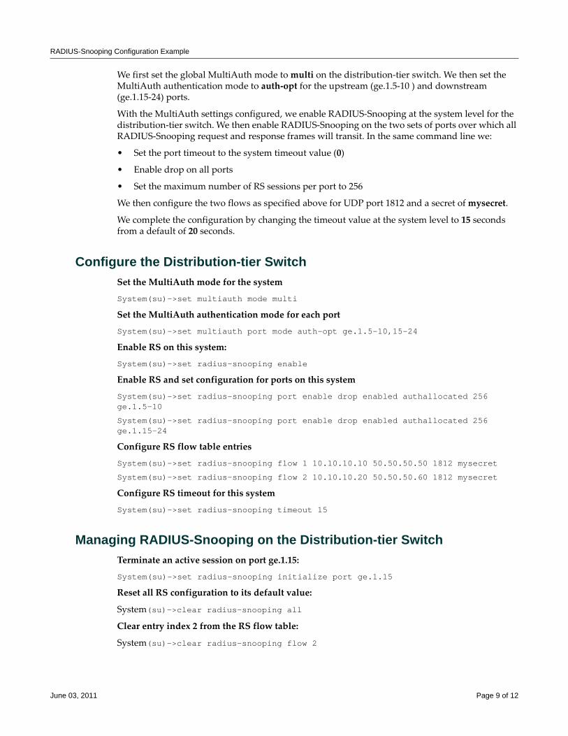
RADIUS-Snooping Configuration Example
We first set the global MultiAuth mode to multi on the distribution‐tier switch. We then set the MultiAuth authentication mode to auth‐opt for the upstream (ge.1.5‐10 ) and downstream (ge.1.15‐24) ports.
With the MultiAuth settings configured, we enable RADIUS‐Snooping at the system level for the distribution‐tier switch. We then enable RADIUS‐Snooping on the two sets of ports over which all RADIUS‐Snooping request and response frames will transit. In the same command line we:
• Set the port timeout to the system timeout value (0)
• Enable drop on all ports
• Set the maximum number of RS sessions per port to 256
We then configure the two flows as specified above for UDP port 1812 and a secret of mysecret.
We complete the configuration by changing the timeout value at the system level to 15 seconds from a default of 20 seconds.
Configure the Distribution-tier SwitchSet the MultiAuth mode for the system
System(su)->set multiauth mode multi
Set the MultiAuth authentication mode for each port
System(su)->set multiauth port mode auth-opt ge.1.5-10,15-24
Enable RS on this system:
System(su)->set radius-snooping enable
Enable RS and set configuration for ports on this system
System(su)->set radius-snooping port enable drop enabled authallocated 256 ge.1.5-10
System(su)->set radius-snooping port enable drop enabled authallocated 256 ge.1.15-24
Configure RS flow table entries
System(su)->set radius-snooping flow 1 10.10.10.10 50.50.50.50 1812 mysecret
System(su)->set radius-snooping flow 2 10.10.10.20 50.50.50.60 1812 mysecret
Configure RS timeout for this system
System(su)->set radius-snooping timeout 15
Managing RADIUS-Snooping on the Distribution-tier SwitchTerminate an active session on port ge.1.15:
System(su)->set radius-snooping initialize port ge.1.15
Reset all RS configuration to its default value:
System(su)->clear radius-snooping all
Clear entry index 2 from the RS flow table:
System(su)->clear radius-snooping flow 2
June 03, 2011 Page 9 of 12
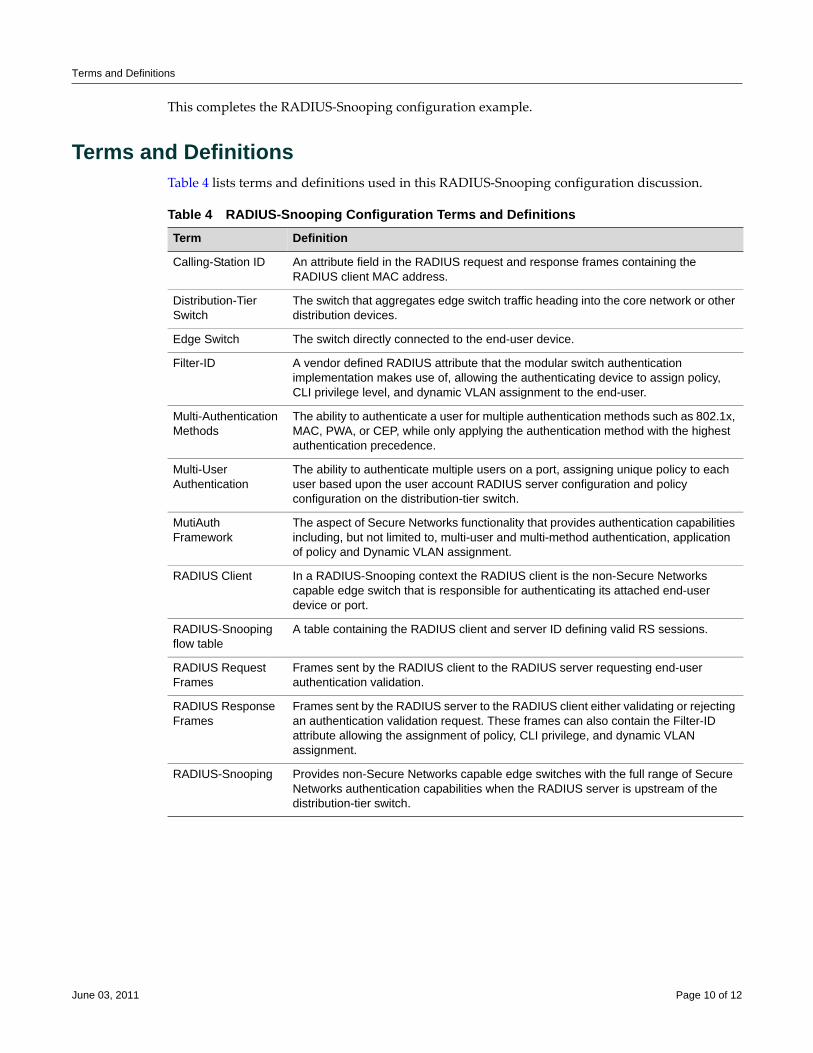
Terms and Definitions
This completes the RADIUS‐Snooping configuration example.
Terms and DefinitionsTable 4 lists terms and definitions used in this RADIUS‐Snooping configuration discussion.
Table 4 RADIUS-Snooping Configuration Terms and Definitions Term Definition
Calling-Station ID An attribute field in the RADIUS request and response frames containing the RADIUS client MAC address.
Distribution-Tier Switch
The switch that aggregates edge switch traffic heading into the core network or other distribution devices.
Edge Switch The switch directly connected to the end-user device.
Filter-ID A vendor defined RADIUS attribute that the modular switch authentication implementation makes use of, allowing the authenticating device to assign policy, CLI privilege level, and dynamic VLAN assignment to the end-user.
Multi-Authentication Methods
The ability to authenticate a user for multiple authentication methods such as 802.1x, MAC, PWA, or CEP, while only applying the authentication method with the highest authentication precedence.
Multi-User Authentication
The ability to authenticate multiple users on a port, assigning unique policy to each user based upon the user account RADIUS server configuration and policy configuration on the distribution-tier switch.
MutiAuth Framework
The aspect of Secure Networks functionality that provides authentication capabilities including, but not limited to, multi-user and multi-method authentication, application of policy and Dynamic VLAN assignment.
RADIUS Client In a RADIUS-Snooping context the RADIUS client is the non-Secure Networks capable edge switch that is responsible for authenticating its attached end-user device or port.
RADIUS-Snooping flow table
A table containing the RADIUS client and server ID defining valid RS sessions.
RADIUS Request Frames
Frames sent by the RADIUS client to the RADIUS server requesting end-user authentication validation.
RADIUS Response Frames
Frames sent by the RADIUS server to the RADIUS client either validating or rejecting an authentication validation request. These frames can also contain the Filter-ID attribute allowing the assignment of policy, CLI privilege, and dynamic VLAN assignment.
RADIUS-Snooping Provides non-Secure Networks capable edge switches with the full range of Secure Networks authentication capabilities when the RADIUS server is upstream of the distribution-tier switch.
June 03, 2011 Page 10 of 12
Revision History
Enterasys Networks reserves the right to make changes in specifications and other information contained in this document and its web site without prior notice. The reader should in all cases consult Enterasys Networks to determine whether any such changes have been made.
The hardware, firmware, or software described in this document is subject to change without notice.
IN NO EVENT SHALL ENTERASYS NETWORKS BE LIABLE FOR ANY INCIDENTAL, INDIRECT, SPECIAL, OR CONSEQUENTIAL DAMAGES WHATSOEVER (INCLUDING BUT NOT LIMITED TO LOST PROFITS) ARISING OUT OF OR RELATED TO THIS DOCUMENT, WEB SITE, OR THE INFORMATION CONTAINED IN THEM, EVEN IF ENTERASYS NETWORKS HAS BEEN ADVISED OF, KNEW OF, OR SHOULD HAVE KNOWN OF, THE POSSIBILITY OF SUCH DAMAGES.
Enterasys Networks, Inc.50 Minuteman RoadAndover, MA 01810
© 2011 Enterasys Networks, Inc. All rights reserved.
ENTERASYS, ENTERASYS NETWORKS, ENTERASYS NETSIGHT, LANVIEW, WEBVIEW, S‐SERIES, and any logos associated therewith, are trademarks or registered trademarks of Enterasys Networks, Inc., in the United States and other countries. For a complete list of Enterasys trademarks, see http://www.enterasys.com/company/trademarks.aspx.
All other product names mentioned in this manual may be trademarks or registered trademarks of their respective companies.
Date Description
11/07/2008 New Document.
04/16/2009 Added 256 MB on all modules requirement. Added MultiAuth configuration information.
06/03/2011 Updated for S-Series and K-Series.

Terms and Definitions
June 03, 2011 Page 12 of 12

Configuring SNMP
This chapter provides the following information about configuring and monitoring SNMP on Enterasys® N‐Series, S‐Series, and K‐Series modular switches, A‐Series, B‐Series, C‐Series stackable fixed switches, and D‐Series, G‐Series, and I‐Series standalone fixed switches
What Is SNMP?The Simple Network Management Protocol (SNMP) is an application layer protocol that facilitates the exchange of management information between network devices. The most widely used management protocol on Internet Protocol (IP) networks, it helps you monitor network performance, troubleshoot problems, and plan for network growth.
SNMP’s simplicity lies in the fact that it uses a basic set of command messages to relay notifications of events and error conditions over a connectionless communication link.
Most network devices support the three versions of the protocol: SNMPv1, SNMPv2c, and SNMPv3. The latest version, SNMPv3, provides enhanced security and administrative features as described in this document.
Why Would I Use SNMP in My Network?SNMP is a simple, cost‐effective tool for monitoring your network devices for conditions that warrant administrative attention. It is widely used because it is:
• Easily integrated into your existing LAN topology
• Based on an open standard, making it non‐proprietary and well documented
• Flexible enough to communicate the specific conditions you need monitored in your network
For information about... Refer to page...
What Is SNMP? 1
Why Would I Use SNMP in My Network? 1
How Do I Implement SNMP? 2
SNMP Overview 2
SNMP Support on Enterasys Devices 4
Configuring SNMP 8
Reviewing SNMP Settings 21
Note: For information about configuring SNMP on the X-Series, refer to the X-Series Configuration Guide.
March 28, 2011 Page 1 of 27
How Do I Implement SNMP?
• A common management platform supported by many network devices
How Do I Implement SNMP?You can implement SNMP on Enterasys switching devices using simple CLI commands as described in this document. The configuration process involves the following tasks:
1. Creating users and groups allowed to manage the network through SNMP
2. Setting security access rights
3. Setting SNMP Management Information Base (MIB) view attributes
4. Setting target parameters to control the formatting of SNMP notification messages
5. Setting target addresses to control where SNMP notifications are sent
6. Setting SNMP notification parameters (filters)
7. Reviewing SNMP statistics
SNMP OverviewIt is helpful to understand the following SNMP components described in this section:
Manager/Agent Model ComponentsSNMP provides a message format for communication between managers and agents, which use a MIB and a relatively small set of commands to exchange information. The SNMP manager can be part of a network management system, such as Enterasys NetSight®, while the agent and MIB reside on the switch.
The SNMP agent acts upon requests from the manager to either collect data from the MIB or set data into the MIB. A repository for information about device parameters and network data, the MIB is organized in a tree structure in which individual variables are represented as leaves on the branches. A unique object identifier (OID) distinguishes each variable in the MIB and is the means by which the manager and agent specify which managed elements are changed.
An agent can send unsolicited notification messages (also known as traps or informs) alerting the SNMP manager to a condition on the network. These conditions include such things as improper user authentication, restarts, link status (up or down), MAC address tracking, closing of a TCP connection, loss of connection to a neighbor, or other significant events.
Message FunctionsSNMP uses five basic message types (Get, Get Next, Get Response, Set, and Trap) to communicate between the manager and the agent. The Get and Get Next messages allow the manager to request
For information about... Refer to page...
Manager/Agent Model Components 2
Message Functions 2
Access to MIB Objects 3
March 28, 2011 Page 2 of 27
SNMP Overview
information for a specific variable. The agent, upon receiving a Get or Get Next message, will issue a Get Response message to the manager with either the information requested or an error indication about why the request cannot be processed.
A Set message allows the manager to request a change to a specific variable. The agent then responds with a Get Response message indicating the change has been made or an error indication about why the change cannot be made.
A trap or inform message allows the agent to spontaneously inform the manager of an “important” event in the network.
The SNMP manager and agent use information in the MIB to perform the operations described in Table 1.
Trap Versus Inform MessagesAs compared to earlier versions, SNMPv3 provides a higher degree of reliability for notifying management stations when critical events occur. Traditionally, SNMP agents communicated events to SNMP managers via “traps.” However, if a temporary network problem prevented the manager from receiving the trap, then the trap would be lost. SNMPv3 provides “informs”, which are a more reliable form of traps. The SNMP agent initiates the inform process by sending an inform request to the manager. The manger responds to the inform request to acknowledge receipt of the message. If the inform is not received by the manager, the inform request will timeout and a new inform request will be sent. Subsequent inform requests will be sent as previous requests time‐out until either an acknowledgement is received from the manager, or until a pre‐specified retry‐count is reached.
Access to MIB ObjectsSNMP uses the following authentication methods to grant user access to MIB objects and functions.
Table 1 SNMP Message FunctionsOperation Function
get-request Retrieves a value from a specific variable.
get-next-request Retrieves a value from a variable within a table.1
1. With this operation, an SNMP manager does not need to know the exact variable name. A sequential search isperformed to find the needed variable from within a table.
get-bulk-request2
2. The get-bulk operation is only supported in SNMPv2c or later.
Retrieves large blocks of data, such as multiple rows in a table, that would otherwise require the transmission of many small blocks of data.
get-response Replies to a get-request, get-next-request, and set-request sent by a management station.
set-request Stores a value in a specific variable.
trap | inform3
3. Inform notifications are only supported in SNMPv3.
Unsolicited message sent by an SNMP agent to an SNMP manager when an event has occurred.
March 28, 2011 Page 3 of 27
SNMP Support on Enterasys Devices
Community Name StringsEarlier SNMP versions (v1 and v2c) rely on community name strings for authentication. In order for the network management station (NMS) to access the switch, the community string definitions on the NMS must match at least one of the three community string definitions on the switch. A community string can have one of these attributes:
• Read‐only (ro)—Gives read access to authorized management stations to all objects in the MIB except the community strings, but does not allow write access.
• Read‐write (rw)—Gives read and write access to authorized management stations to all objects in the MIB, but does not allow access to the community strings.
User-BasedSNMPv3 provides a User‐Based Security Model (USM) which relies on a user name match for authenticated access to network management components.
Refer to “Security Models and Levels” on page 7 for more information.
SNMP Support on Enterasys Devices
By default, SNMP Version 1 (SNMPv1) is configured on Enterasys switches. The default configuration includes a single community name ‐ public ‐ which grants read‐write access to the whole MIB tree for both SNMPv1 and SNMPv2c.
This section provides the following information about SNMP support on Enterasys devices:
Versions SupportedEnterasys devices support three versions of SNMP:
• Version 1 (SNMPv1) — This is the initial implementation of SNMP. Refer to RFC 1157 for a full description of functionality.
• Version 2 (SNMPv2c) — The second release of SNMP, described in RFC 1907, has additions and enhancements to data types, counter size, and protocol operations.
• Version 3 (SNMPv3) — This is the most recent version of SNMP, and includes significant enhancements to administration and security. The major difference between SNMPv3 and earlier versions is that v3 provides a User‐Based Security Model (USM) to associate users with managed access to security information. In addition to better security and better access
Note: This guide describes features supported on the Enterasys N-Series, S-Series, K-Series, stackable, and standalone switch platforms. For information on Enterasys X Router support, refer to the Enterasys X-Series Configuration Guide.
For information about... Refer to page...
Versions Supported 4
Terms and Definitions 5
Security Models and Levels 7
Access Control 7
March 28, 2011 Page 4 of 27
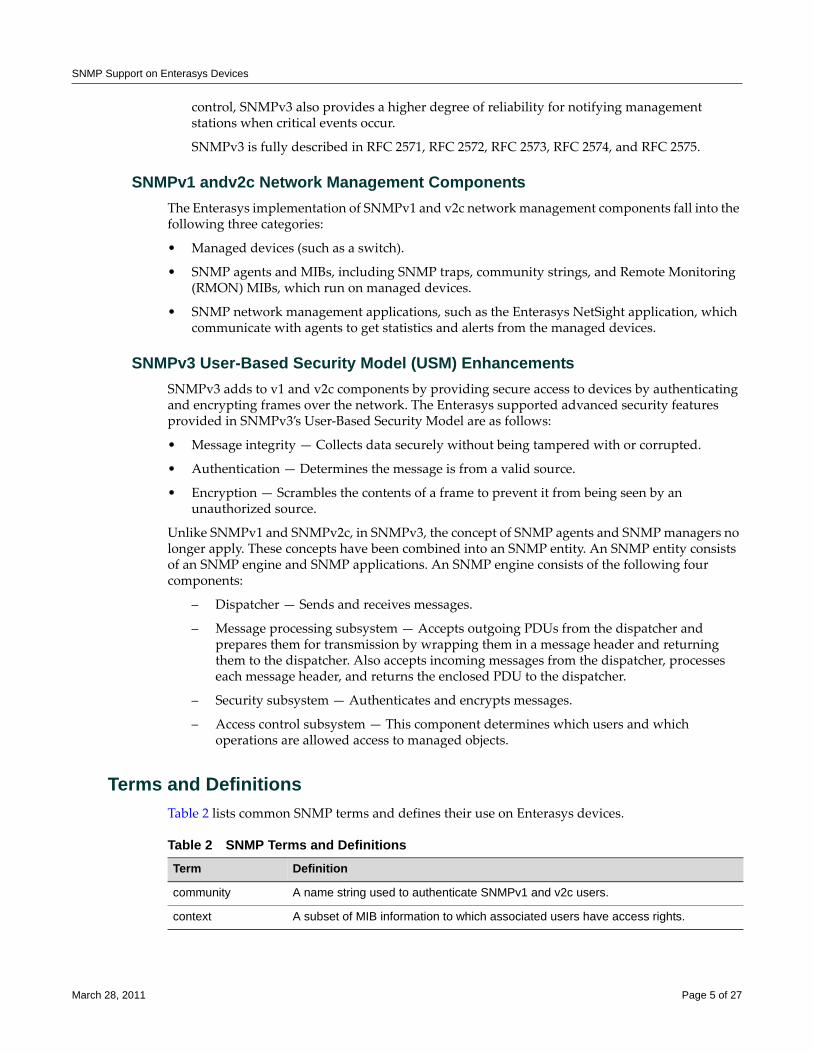
SNMP Support on Enterasys Devices
control, SNMPv3 also provides a higher degree of reliability for notifying management stations when critical events occur.
SNMPv3 is fully described in RFC 2571, RFC 2572, RFC 2573, RFC 2574, and RFC 2575.
SNMPv1 andv2c Network Management ComponentsThe Enterasys implementation of SNMPv1 and v2c network management components fall into the following three categories:
• Managed devices (such as a switch).
• SNMP agents and MIBs, including SNMP traps, community strings, and Remote Monitoring (RMON) MIBs, which run on managed devices.
• SNMP network management applications, such as the Enterasys NetSight application, which communicate with agents to get statistics and alerts from the managed devices.
SNMPv3 User-Based Security Model (USM) EnhancementsSNMPv3 adds to v1 and v2c components by providing secure access to devices by authenticating and encrypting frames over the network. The Enterasys supported advanced security features provided in SNMPv3’s User‐Based Security Model are as follows:
• Message integrity — Collects data securely without being tampered with or corrupted.
• Authentication — Determines the message is from a valid source.
• Encryption — Scrambles the contents of a frame to prevent it from being seen by an unauthorized source.
Unlike SNMPv1 and SNMPv2c, in SNMPv3, the concept of SNMP agents and SNMP managers no longer apply. These concepts have been combined into an SNMP entity. An SNMP entity consists of an SNMP engine and SNMP applications. An SNMP engine consists of the following four components:
– Dispatcher — Sends and receives messages.
– Message processing subsystem — Accepts outgoing PDUs from the dispatcher and prepares them for transmission by wrapping them in a message header and returning them to the dispatcher. Also accepts incoming messages from the dispatcher, processes each message header, and returns the enclosed PDU to the dispatcher.
– Security subsystem — Authenticates and encrypts messages.
– Access control subsystem — This component determines which users and which operations are allowed access to managed objects.
Terms and DefinitionsTable 2 lists common SNMP terms and defines their use on Enterasys devices.
Table 2 SNMP Terms and DefinitionsTerm Definition
community A name string used to authenticate SNMPv1 and v2c users.
context A subset of MIB information to which associated users have access rights.
March 28, 2011 Page 5 of 27
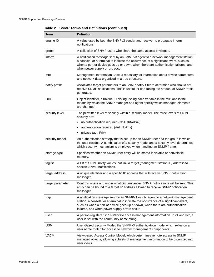
SNMP Support on Enterasys Devices
engine ID A value used by both the SNMPv3 sender and receiver to propagate inform notifications.
group A collection of SNMP users who share the same access privileges.
inform A notification message sent by an SNMPv3 agent to a network management station, a console, or a terminal to indicate the occurrence of a significant event, such as when a port or device goes up or down, when there are authentication failures, and when power supply errors occur.
MIB Management Information Base, a repository for information about device parameters and network data organized in a tree structure.
notify profile Associates target parameters to an SNMP notify filter to determine who should not receive SNMP notifications. This is useful for fine-tuning the amount of SNMP traffic generated.
OID Object Identifier, a unique ID distinguishing each variable in the MIB and is the means by which the SNMP manager and agent specify which managed elements are changed.
security level The permitted level of security within a security model. The three levels of SNMP security are:
• no authentication required (NoAuthNoPriv)
• authentication required (AuthNoPriv)
• privacy (authPriv)
security model An authentication strategy that is set up for an SNMP user and the group in which the user resides. A combination of a security model and a security level determines which security mechanism is employed when handling an SNMP frame.
storage type Specifies whether an SNMP user entry will be stored in volatile or nonvolatile memory.
taglist A list of SNMP notify values that link a target (managment station IP) address to specific SNMP notifications.
target address A unique identifier and a specific IP address that will receive SNMP notification messages.
target parameter Controls where and under what circumstances SNMP notifications will be sent. This entry can be bound to a target IP address allowed to receive SNMP notification messages.
trap A notification message sent by an SNMPv1 or v2c agent to a network management station, a console, or a terminal to indicate the occurrence of a significant event, such as when a port or device goes up or down, when there are authentication failures, and when power supply errors occur.
user A person registered in SNMPv3 to access management information. In v1 and v2c, a user is set with the community name string.
USM User-Based Security Model, the SNMPv3 authenticatiion model which relies on a user name match for access to network management components.
VACM View-based Access Control Model, which determines remote access to SNMP managed objects, allowing subsets of management information to be organized into user views.
Table 2 SNMP Terms and Definitions (continued)Term Definition
March 28, 2011 Page 6 of 27
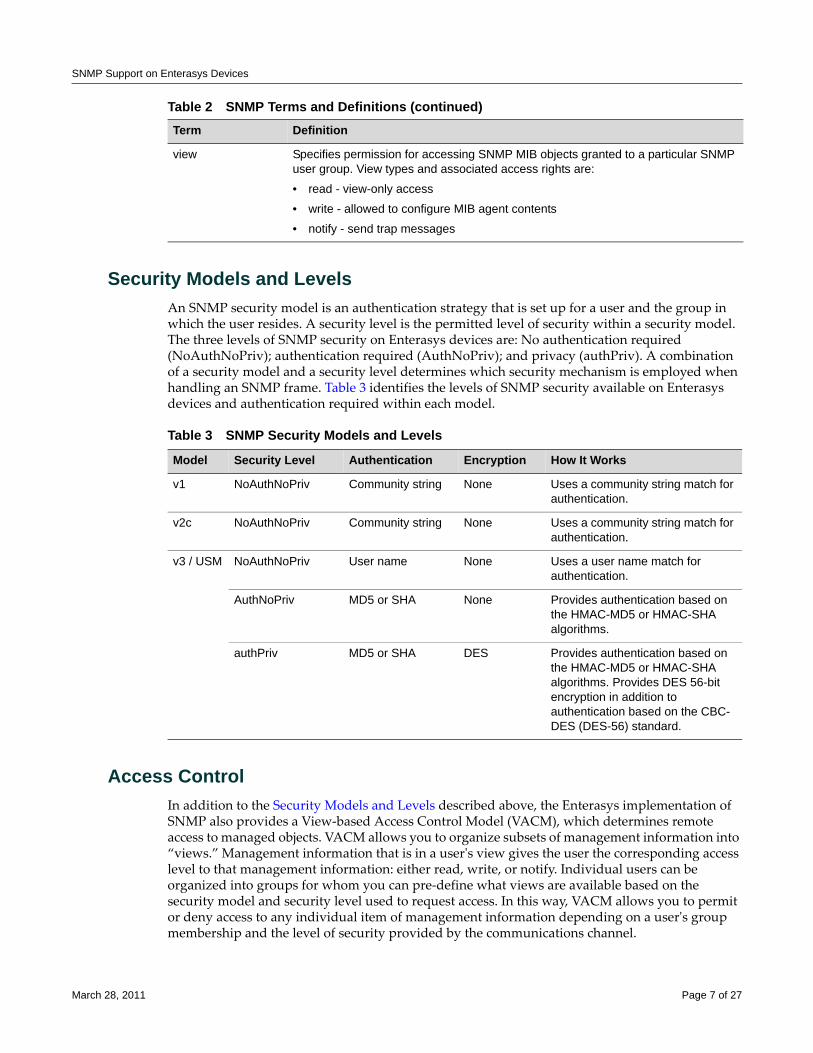
SNMP Support on Enterasys Devices
Security Models and LevelsAn SNMP security model is an authentication strategy that is set up for a user and the group in which the user resides. A security level is the permitted level of security within a security model. The three levels of SNMP security on Enterasys devices are: No authentication required (NoAuthNoPriv); authentication required (AuthNoPriv); and privacy (authPriv). A combination of a security model and a security level determines which security mechanism is employed when handling an SNMP frame. Table 3 identifies the levels of SNMP security available on Enterasys devices and authentication required within each model.
Access ControlIn addition to the Security Models and Levels described above, the Enterasys implementation of SNMP also provides a View‐based Access Control Model (VACM), which determines remote access to managed objects. VACM allows you to organize subsets of management information into “views.” Management information that is in a userʹs view gives the user the corresponding access level to that management information: either read, write, or notify. Individual users can be organized into groups for whom you can pre‐define what views are available based on the security model and security level used to request access. In this way, VACM allows you to permit or deny access to any individual item of management information depending on a userʹs group membership and the level of security provided by the communications channel.
view Specifies permission for accessing SNMP MIB objects granted to a particular SNMP user group. View types and associated access rights are:
• read - view-only access
• write - allowed to configure MIB agent contents
• notify - send trap messages
Table 2 SNMP Terms and Definitions (continued)Term Definition
Table 3 SNMP Security Models and Levels
Model Security Level Authentication Encryption How It Works
v1 NoAuthNoPriv Community string None Uses a community string match for authentication.
v2c NoAuthNoPriv Community string None Uses a community string match for authentication.
v3 / USM NoAuthNoPriv User name None Uses a user name match for authentication.
AuthNoPriv MD5 or SHA None Provides authentication based on the HMAC-MD5 or HMAC-SHA algorithms.
authPriv MD5 or SHA DES Provides authentication based on the HMAC-MD5 or HMAC-SHA algorithms. Provides DES 56-bit encryption in addition to authentication based on the CBC-DES (DES-56) standard.
March 28, 2011 Page 7 of 27
Configuring SNMP
Configuring SNMPThis section provides the following information about configuring SNMP on Enterasys devices:
Configuration BasicsCompleting an SNMP configuration on an Enterasys device involves defining users who will be authorized to receive SNMP notifications about network events, associating security (target) paramenters, access rights and MIB views to those users, and specifying an IP address where they will receive notifications. The basic steps in this process are:
1. Creating a name that will act as an SNMP user password:
– This will be a community name for an SNMPv1 or v2c configuration, or.
– A user name for an SNMPv3 configuration.
2. Creating a group for the user named in Step 1.
3. Creating access rights for the user group named in Step 2.
4. Defining MIB view(s) for the user group.
5. Creating a target parameters entry to associate security and authorization criteria to the users created in Step 1.
6. Verifying if any applicable SNMP notification entries exist, or creating a new one. You will use this entry to send SNMP notification messages to the appropriate targets configured in Step 5.
7. Creating a target address entry to bind a management IP address to:
– The notification entry and tag name created in Step 6, and
– The target parameters entry created in Step 5.
How SNMP Processes a Notification Configuration In order to send a trap or inform notification requested by a MIB code, the SNMP agent requires the equivalent of a trap “door”, a “key” to unlock the door, and a “procedure” for crossing the doorstep. To determine if all these elements are in place, the SNMP agent processes a device configuration as follows:
For information about... Refer to page...
Configuration Basics 8
How SNMP Processes a Notification Configuration 8
SNMP Defaults 9
Configuring SNMPv1/SNMPv2c 10
Configuring SNMPv3 11
Configuring Secure SNMP Community Names 18
Note: Commands for configuring SNMP on Enterasys devices are independent during the SNMP setup process. For instance, target parameters can be specified when setting up optional notification filters — even though these parameters have not yet been created with the set snmp targetparams command. The steps in this section are a guideline to configuring SNMP and do not necessarily need to be executed in this order.
March 28, 2011 Page 8 of 27
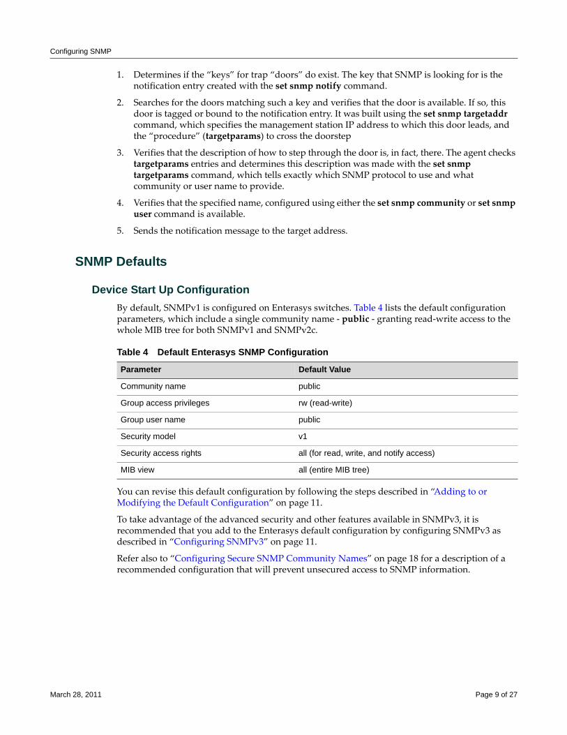
Configuring SNMP
1. Determines if the “keys” for trap “doors” do exist. The key that SNMP is looking for is the notification entry created with the set snmp notify command.
2. Searches for the doors matching such a key and verifies that the door is available. If so, this door is tagged or bound to the notification entry. It was built using the set snmp targetaddr command, which specifies the management station IP address to which this door leads, and the “procedure” (targetparams) to cross the doorstep
3. Verifies that the description of how to step through the door is, in fact, there. The agent checks targetparams entries and determines this description was made with the set snmp targetparams command, which tells exactly which SNMP protocol to use and what community or user name to provide.
4. Verifies that the specified name, configured using either the set snmp community or set snmp user command is available.
5. Sends the notification message to the target address.
SNMP Defaults
Device Start Up ConfigurationBy default, SNMPv1 is configured on Enterasys switches. Table 4 lists the default configuration parameters, which include a single community name ‐ public ‐ granting read‐write access to the whole MIB tree for both SNMPv1 and SNMPv2c.
You can revise this default configuration by following the steps described in “Adding to or Modifying the Default Configuration” on page 11.
To take advantage of the advanced security and other features available in SNMPv3, it is recommended that you add to the Enterasys default configuration by configuring SNMPv3 as described in “Configuring SNMPv3” on page 11.
Refer also to “Configuring Secure SNMP Community Names” on page 18 for a description of a recommended configuration that will prevent unsecured access to SNMP information.
Table 4 Default Enterasys SNMP Configuration
Parameter Default Value
Community name public
Group access privileges rw (read-write)
Group user name public
Security model v1
Security access rights all (for read, write, and notify access)
MIB view all (entire MIB tree)
March 28, 2011 Page 9 of 27
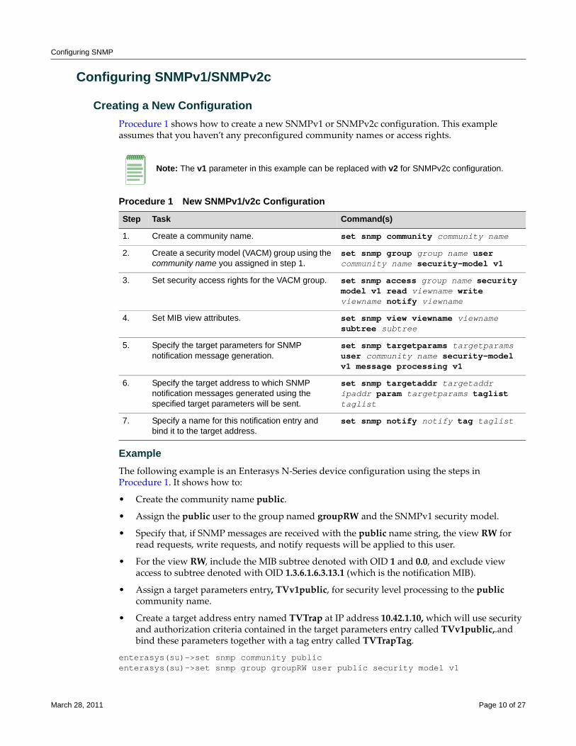
Configuring SNMP
Configuring SNMPv1/SNMPv2c
Creating a New ConfigurationProcedure 1 shows how to create a new SNMPv1 or SNMPv2c configuration. This example assumes that you haven’t any preconfigured community names or access rights.
ExampleThe following example is an Enterasys N‐Series device configuration using the steps in Procedure 1. It shows how to:
• Create the community name public.
• Assign the public user to the group named groupRW and the SNMPv1 security model.
• Specify that, if SNMP messages are received with the public name string, the view RW for read requests, write requests, and notify requests will be applied to this user.
• For the view RW, include the MIB subtree denoted with OID 1 and 0.0, and exclude view access to subtree denoted with OID 1.3.6.1.6.3.13.1 (which is the notification MIB).
• Assign a target parameters entry, TVv1public, for security level processing to the public community name.
• Create a target address entry named TVTrap at IP address 10.42.1.10, which will use security and authorization criteria contained in the target parameters entry called TVv1public,.and bind these parameters together with a tag entry called TVTrapTag.
enterasys(su)->set snmp community publicenterasys(su)->set snmp group groupRW user public security model v1
Note: The v1 parameter in this example can be replaced with v2 for SNMPv2c configuration.
Procedure 1 New SNMPv1/v2c Configuration
Step Task Command(s)
1. Create a community name. set snmp community community name
2. Create a security model (VACM) group using the community name you assigned in step 1.
set snmp group group name user community name security-model v1
3. Set security access rights for the VACM group. set snmp access group name security model v1 read viewname write viewname notify viewname
4. Set MIB view attributes. set snmp view viewname viewname subtree subtree
5. Specify the target parameters for SNMP notification message generation.
set snmp targetparams targetparams user community name security-model v1 message processing v1
6. Specify the target address to which SNMP notification messages generated using the specified target parameters will be sent.
set snmp targetaddr targetaddr ipaddr param targetparams taglist taglist
7. Specify a name for this notification entry and bind it to the target address.
set snmp notify notify tag taglist
March 28, 2011 Page 10 of 27
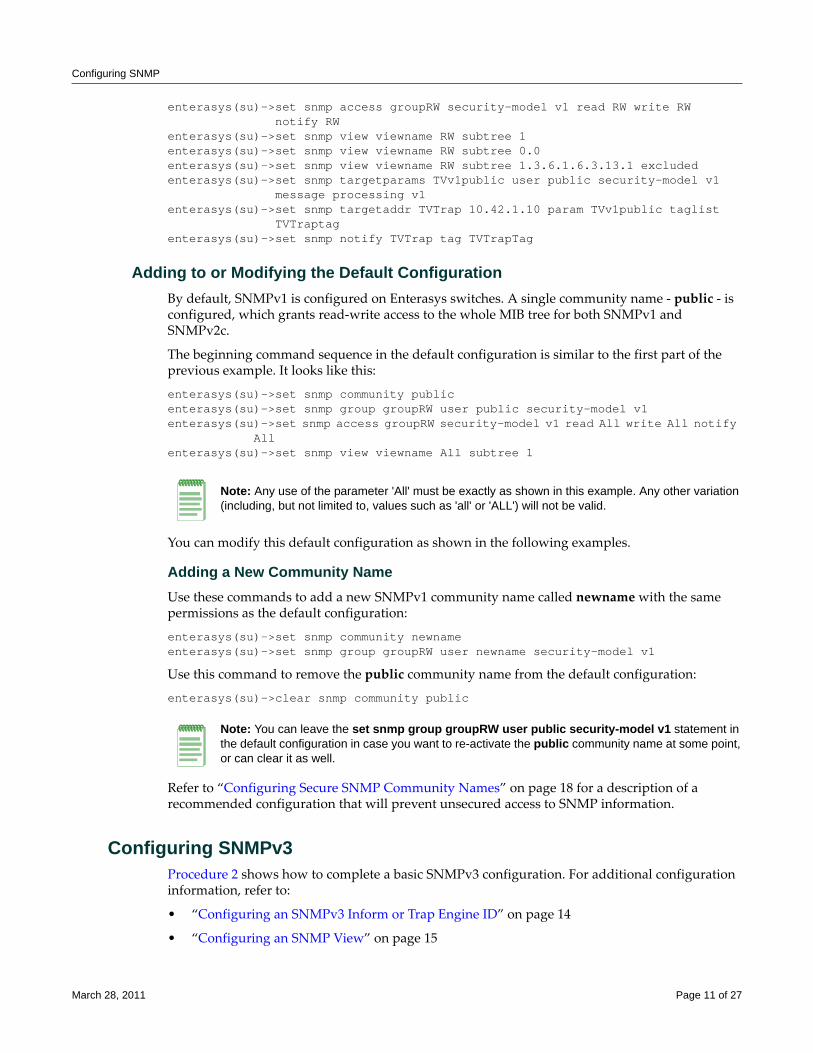
Configuring SNMP
enterasys(su)->set snmp access groupRW security-model v1 read RW write RW notify RWenterasys(su)->set snmp view viewname RW subtree 1enterasys(su)->set snmp view viewname RW subtree 0.0enterasys(su)->set snmp view viewname RW subtree 1.3.6.1.6.3.13.1 excludedenterasys(su)->set snmp targetparams TVv1public user public security-model v1 message processing v1enterasys(su)->set snmp targetaddr TVTrap 10.42.1.10 param TVv1public taglist TVTraptagenterasys(su)->set snmp notify TVTrap tag TVTrapTag
Adding to or Modifying the Default ConfigurationBy default, SNMPv1 is configured on Enterasys switches. A single community name ‐ public ‐ is configured, which grants read‐write access to the whole MIB tree for both SNMPv1 and SNMPv2c.
The beginning command sequence in the default configuration is similar to the first part of the previous example. It looks like this:
enterasys(su)->set snmp community public enterasys(su)->set snmp group groupRW user public security-model v1 enterasys(su)->set snmp access groupRW security-model v1 read All write All notify
All enterasys(su)->set snmp view viewname All subtree 1
You can modify this default configuration as shown in the following examples.
Adding a New Community NameUse these commands to add a new SNMPv1 community name called newname with the same permissions as the default configuration:
enterasys(su)->set snmp community newname enterasys(su)->set snmp group groupRW user newname security-model v1
Use this command to remove the public community name from the default configuration:
enterasys(su)->clear snmp community public
Refer to “Configuring Secure SNMP Community Names” on page 18 for a description of a recommended configuration that will prevent unsecured access to SNMP information.
Configuring SNMPv3Procedure 2 shows how to complete a basic SNMPv3 configuration. For additional configuration information, refer to:
• “Configuring an SNMPv3 Inform or Trap Engine ID” on page 14
• “Configuring an SNMP View” on page 15
Note: Any use of the parameter 'All' must be exactly as shown in this example. Any other variation (including, but not limited to, values such as 'all' or 'ALL') will not be valid.
Note: You can leave the set snmp group groupRW user public security-model v1 statement in the default configuration in case you want to re-activate the public community name at some point, or can clear it as well.
March 28, 2011 Page 11 of 27
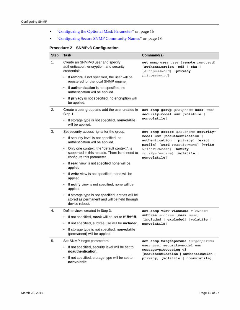
Configuring SNMP
• “Configuring the Optional Mask Parameter” on page 16
• “Configuring Secure SNMP Community Names” on page 18.
Procedure 2 SNMPv3 Configuration
Step Task Command(s)
1. Create an SNMPv3 user and specify authentication, encryption, and security credentials.
• If remote is not specified, the user will be registered for the local SNMP engine.
• If authentication is not specified, no authentication will be applied.
• If privacy is not specified, no encryption will be applied.
set snmp user user [remote remoteid] [authentication {md5 | sha}] [authpassword] [privacy privpassword]
2. Create a user group and add the user created in Step 1.
• If storage type is not specified, nonvolatile will be applied.
set snmp group groupname user user security-model usm [volatile | nonvolatile]
3. Set security access rights for the group.
• If security level is not specified, no authentication will be applied.
• Only one context, the “default context”, is supported in this release. There is no need to configure this parameter.
• If read view is not specified none will be applied.
• If write view is not specified, none will be applied.
• If notify view is not specified, none will be applied.
• If storage type is not specified, entries will be stored as permanent and will be held through device reboot.
set snmp access groupname security-model usm [noauthentication | authentication | privacy] [exact | prefix] [read readviewname] [write writeviewname] [notify notifyviewname] [volatile | nonvolatile]
4. Define views created in Step 3.
• If not specified, mask will be set to ff:ff:ff:ff.
• If not specified, subtree use will be included.
• If storage type is not specified, nonvolatile (permanent) will be applied.
set snmp view viewname viewname subtree subtree [mask mask] [included | excluded] [volatile | nonvolatile]
5. Set SNMP target parameters.
• If not specified, security level will be set to noauthentication.
• If not specified, storage type will be set to nonvolatile.
set snmp targetparams targetparams user user security-model usm message-processing v3 [noauthentication | authentication | privacy] [volatile | nonvolatile]
March 28, 2011 Page 12 of 27
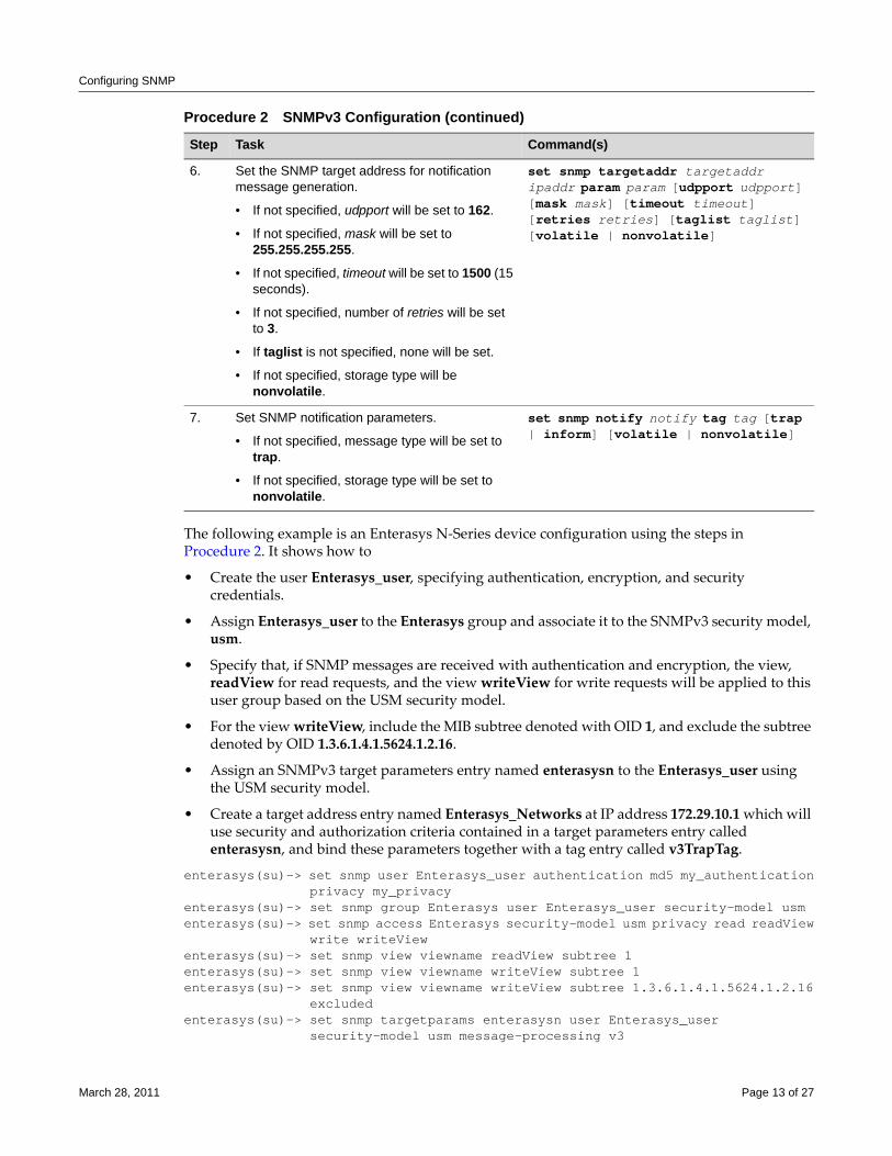
Configuring SNMP
The following example is an Enterasys N‐Series device configuration using the steps in Procedure 2. It shows how to
• Create the user Enterasys_user, specifying authentication, encryption, and security credentials.
• Assign Enterasys_user to the Enterasys group and associate it to the SNMPv3 security model, usm.
• Specify that, if SNMP messages are received with authentication and encryption, the view, readView for read requests, and the view writeView for write requests will be applied to this user group based on the USM security model.
• For the view writeView, include the MIB subtree denoted with OID 1, and exclude the subtree denoted by OID 1.3.6.1.4.1.5624.1.2.16.
• Assign an SNMPv3 target parameters entry named enterasysn to the Enterasys_user using the USM security model.
• Create a target address entry named Enterasys_Networks at IP address 172.29.10.1 which will use security and authorization criteria contained in a target parameters entry called enterasysn, and bind these parameters together with a tag entry called v3TrapTag.
enterasys(su)-> set snmp user Enterasys_user authentication md5 my_authentication privacy my_privacyenterasys(su)-> set snmp group Enterasys user Enterasys_user security-model usmenterasys(su)-> set snmp access Enterasys security-model usm privacy read readView write writeViewenterasys(su)-> set snmp view viewname readView subtree 1enterasys(su)-> set snmp view viewname writeView subtree 1enterasys(su)-> set snmp view viewname writeView subtree 1.3.6.1.4.1.5624.1.2.16 excludedenterasys(su)-> set snmp targetparams enterasysn user Enterasys_user security-model usm message-processing v3
6. Set the SNMP target address for notification message generation.
• If not specified, udpport will be set to 162.
• If not specified, mask will be set to 255.255.255.255.
• If not specified, timeout will be set to 1500 (15 seconds).
• If not specified, number of retries will be set to 3.
• If taglist is not specified, none will be set.
• If not specified, storage type will be nonvolatile.
set snmp targetaddr targetaddr ipaddr param param [udpport udpport] [mask mask] [timeout timeout] [retries retries] [taglist taglist] [volatile | nonvolatile]
7. Set SNMP notification parameters.
• If not specified, message type will be set to trap.
• If not specified, storage type will be set to nonvolatile.
set snmp notify notify tag tag [trap | inform] [volatile | nonvolatile]
Procedure 2 SNMPv3 Configuration (continued)
Step Task Command(s)
March 28, 2011 Page 13 of 27
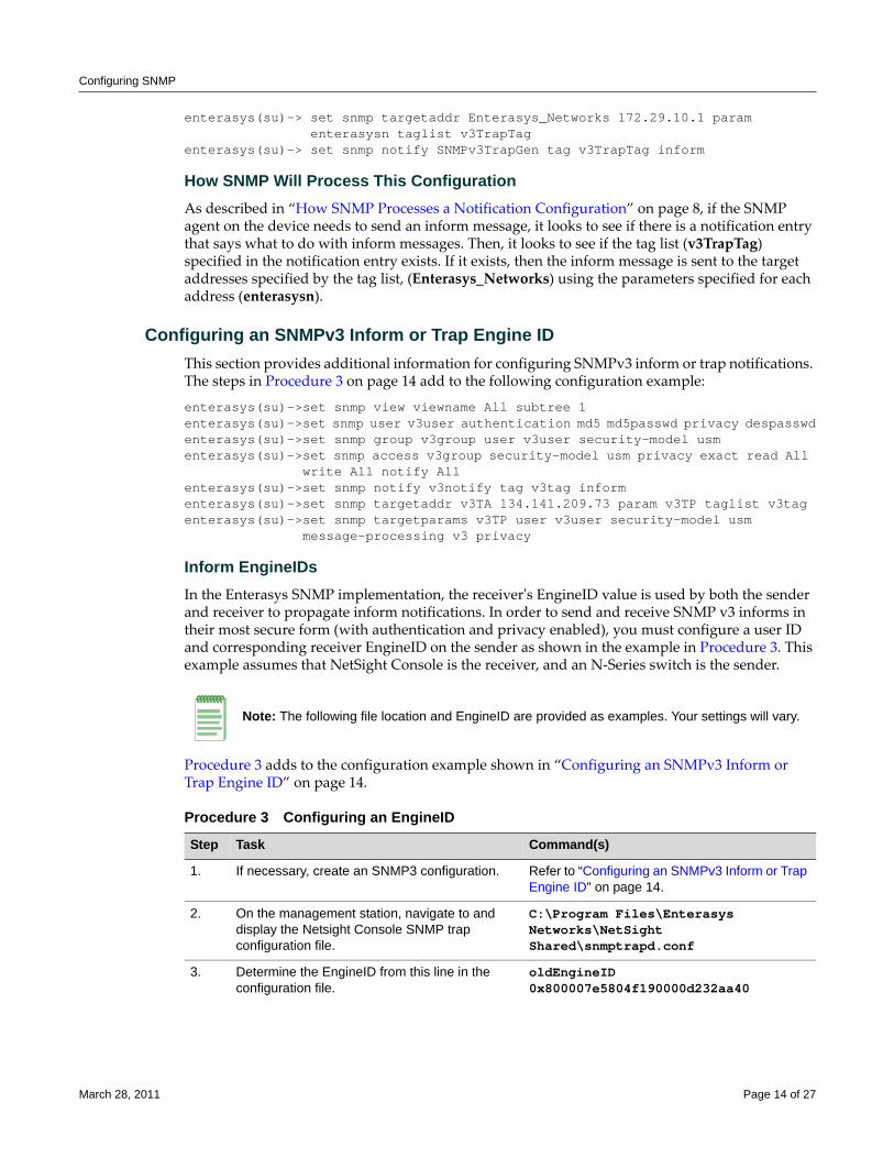
Configuring SNMP
enterasys(su)-> set snmp targetaddr Enterasys_Networks 172.29.10.1 param enterasysn taglist v3TrapTagenterasys(su)-> set snmp notify SNMPv3TrapGen tag v3TrapTag inform
How SNMP Will Process This Configuration As described in “How SNMP Processes a Notification Configuration” on page 8, if the SNMP agent on the device needs to send an inform message, it looks to see if there is a notification entry that says what to do with inform messages. Then, it looks to see if the tag list (v3TrapTag) specified in the notification entry exists. If it exists, then the inform message is sent to the target addresses specified by the tag list, (Enterasys_Networks) using the parameters specified for each address (enterasysn).
Configuring an SNMPv3 Inform or Trap Engine ID This section provides additional information for configuring SNMPv3 inform or trap notifications. The steps in Procedure 3 on page 14 add to the following configuration example:
enterasys(su)->set snmp view viewname All subtree 1enterasys(su)->set snmp user v3user authentication md5 md5passwd privacy despasswdenterasys(su)->set snmp group v3group user v3user security-model usmenterasys(su)->set snmp access v3group security-model usm privacy exact read All write All notify Allenterasys(su)->set snmp notify v3notify tag v3tag inform enterasys(su)->set snmp targetaddr v3TA 134.141.209.73 param v3TP taglist v3tagenterasys(su)->set snmp targetparams v3TP user v3user security-model usm message-processing v3 privacy
Inform EngineIDsIn the Enterasys SNMP implementation, the receiverʹs EngineID value is used by both the sender and receiver to propagate inform notifications. In order to send and receive SNMP v3 informs in their most secure form (with authentication and privacy enabled), you must configure a user ID and corresponding receiver EngineID on the sender as shown in the example in Procedure 3. This example assumes that NetSight Console is the receiver, and an N‐Series switch is the sender.
Procedure 3 adds to the configuration example shown in “Configuring an SNMPv3 Inform or Trap Engine ID” on page 14.
Note: The following file location and EngineID are provided as examples. Your settings will vary.
Procedure 3 Configuring an EngineID
Step Task Command(s)
1. If necessary, create an SNMP3 configuration. Refer to “Configuring an SNMPv3 Inform or Trap Engine ID” on page 14.
2. On the management station, navigate to and display the Netsight Console SNMP trap configuration file.
C:\Program Files\Enterasys Networks\NetSight Shared\snmptrapd.conf
3. Determine the EngineID from this line in the configuration file.
oldEngineID 0x800007e5804f190000d232aa40
March 28, 2011 Page 14 of 27
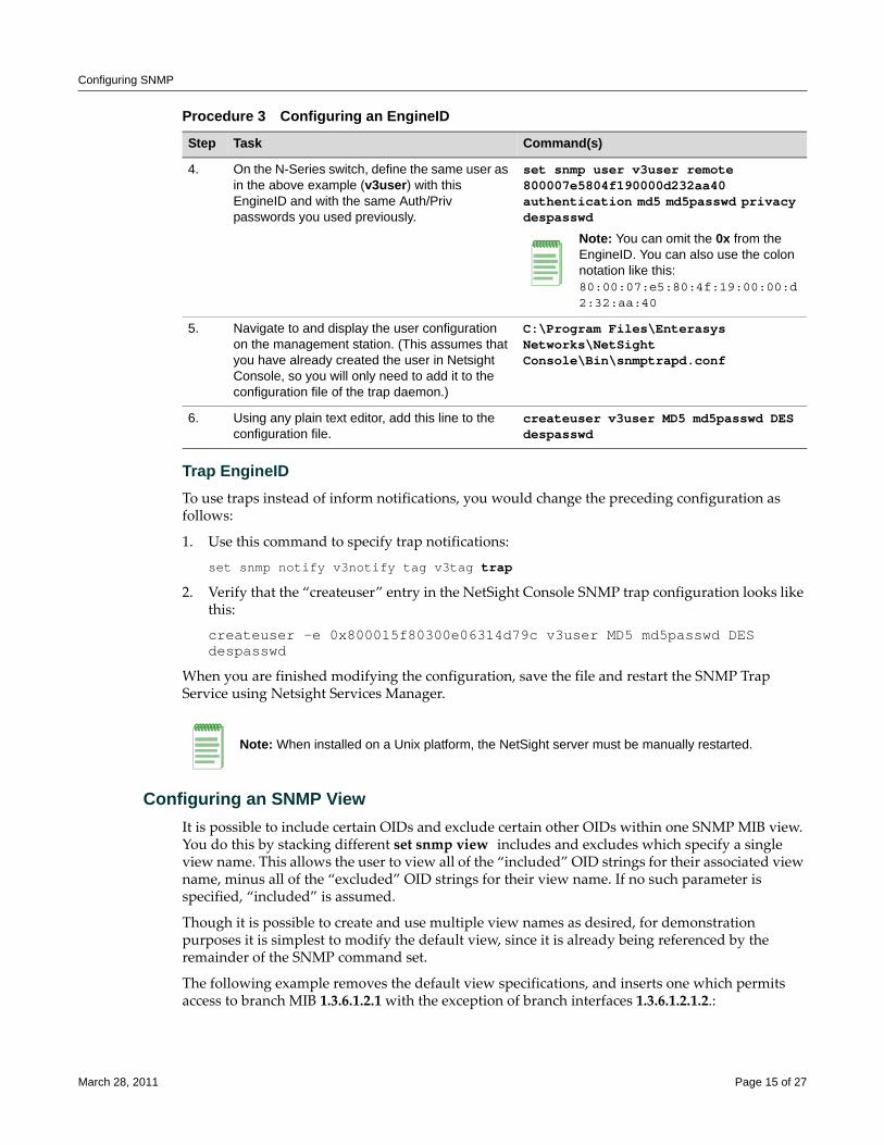
Configuring SNMP
Trap EngineIDTo use traps instead of inform notifications, you would change the preceding configuration as follows:
1. Use this command to specify trap notifications:
set snmp notify v3notify tag v3tag trap
2. Verify that the “createuser” entry in the NetSight Console SNMP trap configuration looks like this:
createuser -e 0x800015f80300e06314d79c v3user MD5 md5passwd DES despasswd
When you are finished modifying the configuration, save the file and restart the SNMP Trap Service using Netsight Services Manager.
Configuring an SNMP ViewIt is possible to include certain OIDs and exclude certain other OIDs within one SNMP MIB view. You do this by stacking different set snmp view includes and excludes which specify a single view name. This allows the user to view all of the “included” OID strings for their associated view name, minus all of the “excluded” OID strings for their view name. If no such parameter is specified, “included” is assumed.
Though it is possible to create and use multiple view names as desired, for demonstration purposes it is simplest to modify the default view, since it is already being referenced by the remainder of the SNMP command set.
The following example removes the default view specifications, and inserts one which permits access to branch MIB 1.3.6.1.2.1 with the exception of branch interfaces 1.3.6.1.2.1.2.:
4. On the N-Series switch, define the same user as in the above example (v3user) with this EngineID and with the same Auth/Priv passwords you used previously.
set snmp user v3user remote 800007e5804f190000d232aa40 authentication md5 md5passwd privacy despasswd
Note: You can omit the 0x from the EngineID. You can also use the colon notation like this:80:00:07:e5:80:4f:19:00:00:d2:32:aa:40
5. Navigate to and display the user configuration on the management station. (This assumes that you have already created the user in Netsight Console, so you will only need to add it to the configuration file of the trap daemon.)
C:\Program Files\Enterasys Networks\NetSight Console\Bin\snmptrapd.conf
6. Using any plain text editor, add this line to the configuration file.
createuser v3user MD5 md5passwd DES despasswd
Note: When installed on a Unix platform, the NetSight server must be manually restarted.
Procedure 3 Configuring an EngineID
Step Task Command(s)
March 28, 2011 Page 15 of 27
Configuring SNMP
enterasys(su)->clear snmp view All 1enterasys(su)->clear snmp view All 0.0enterasys(su)->set snmp view viewname All subtree 1.3.6.1.2.1enterasys(su)->set snmp view viewname All subtree 1.3.6.1.2.1.2 excluded enterasys(su)->show snmp view View Name = All Subtree OID = 1.3.6.1.2.1 Subtree mask = View Type = included Storage type = nonVolatile Row status = active View Name = All Subtree OID = 1.3.6.1.2.1.2 Subtree mask = View Type = excluded Storage type = nonVolatile Row status = active
You can test this configuration using any MIB browser directed to the IP of the configured device and using the default community name public associated with the view All. If configured correctly, only your specified sections of the MIBs will be visible.
Configuring the Optional Mask Parameter
As defined in RFC2575, an SNMP mask is an optional parameter of the set snmp view command. You can use a mask to modify a view inclusion, designating certain octets of an OID string as wild‐card “donʹt care” values. Once defined, you can view within a MIB branch (using a MIB browser such as that offered within the NetSight suite of products) only those leaves associated with specific items, such as designated port numbers, MAC addresses, and IP addresses.
For example, the RMON Statistics MIB branch is defined as follows, with the leaves defined within that branch each having multiple iterations, one for each port.
etherStatsEntry=1.3.6.1.2.1.16.1.1.1 etherStatsIndex=1.3.6.1.2.1.16.1.1.1.1.<port> etherStatsDataSource=1.3.6.1.2.1.16.1.1.1.2.<port> etherStatsDropEvents=1.3.6.1.2.1.16.1.1.1.3.<port> etherStatsOctets=1.3.6.1.2.1.16.1.1.1.4.<port> etherStatsPkts=1.3.6.1.2.1.16.1.1.1.5.<port> etherStatsBroadcastPkts=1.3.6.1.2.1.16.1.1.1.6.<port> etherStatsMulticastPkts=1.3.6.1.2.1.16.1.1.1.7.<port> etherStatsCRCAlignErrors=1.3.6.1.2.1.16.1.1.1.8.<port> etherStatsUndersizePkts=1.3.6.1.2.1.16.1.1.1.9.<port> etherStatsOversizePkts=1.3.6.1.2.1.16.1.1.1.10.<port> etherStatsFragments=1.3.6.1.2.1.16.1.1.1.11.<port> etherStatsJabbers=1.3.6.1.2.1.16.1.1.1.12.<port> etherStatsCollisions=1.3.6.1.2.1.16.1.1.1.13.<port> etherStatsPkts64Octets=1.3.6.1.2.1.16.1.1.1.14.<port> etherStatsPkts65to127Octets=1.3.6.1.2.1.16.1.1.1.15.<port> etherStatsPkts128to255Octets=1.3.6.1.2.1.16.1.1.1.16.<port> etherStatsPkts256to511Octets=1.3.6.1.2.1.16.1.1.1.17.<port> etherStatsPkts512to1023Octets=1.3.6.1.2.1.16.1.1.1.18.<port>
Note: The mechanics of determining exactly how to configure the optional mask parameter make for an inefficient use of time if you will only be using the query once. However, for data retrieved repeatedly, using the method described in the following examples can prevent the unnecessary transfer of much SNMP data over your network.
March 28, 2011 Page 16 of 27
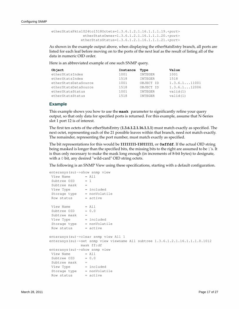
Configuring SNMP
etherStatsPkts1024to1518Octets=1.3.6.1.2.1.16.1.1.1.19.<port> etherStatsOwner=1.3.6.1.2.1.16.1.1.1.20.<port> etherStatsStatus=1.3.6.1.2.1.16.1.1.1.21.<port>
As shown in the example output above, when displaying the etherStatsEntry branch, all ports are listed for each leaf before moving on to the ports of the next leaf as the result of listing all of the data in numeric OID order.
Here is an abbreviated example of one such SNMP query.
Object Instance Type Value etherStatsIndex 1001 INTEGER 1001 etherStatsIndex 1518 INTEGER 1518 etherStatsDataSource 1001 OBJECT ID 1.3.6.1...11001 etherStatsDataSource 1518 OBJECT ID 1.3.6.1...12006 etherStatsStatus 1001 INTEGER valid(1) etherStatsStatus 1518 INTEGER valid(1)
ExampleThis example shows you how to use the mask parameter to significantly refine your query output, so that only data for specified ports is returned. For this example, assume that N‐Series slot 1 port 12 is of interest.
The first ten octets of the etherStatsEntry (1.3.6.1.2.1.16.1.1.1) must match exactly as specified. The next octet, representing each of the 21 possible leaves within that branch, need not match exactly. The remainder, representing the port number, must match exactly as specified.
The bit representations for this would be 11111111‐11011111, or 0xffdf. If the actual OID string being masked is longer than the specified bits, the missing bits to the right are assumed to be 1ʹs. It is thus only necessary to make the mask long enough (in increments of 8‐bit bytes) to designate, with a 0 bit, any desired ʺwild‐cardʺ OID string octets.
The following is an SNMP View using these specifications, starting with a default configuration.
enterasys(su)->show snmp view View Name = All Subtree OID = 1 Subtree mask = View Type = included Storage type = nonVolatile Row status = active View Name = All Subtree OID = 0.0 Subtree mask = View Type = included Storage type = nonVolatile Row status = active enterasys(su)->clear snmp view All 1enterasys(su)->set snmp view viewname All subtree 1.3.6.1.2.1.16.1.1.1.0.1012 mask ff:df enterasys(su)->show snmp view View Name = All Subtree OID = 0.0 Subtree mask = View Type = included Storage type = nonVolatile Row status = active
March 28, 2011 Page 17 of 27
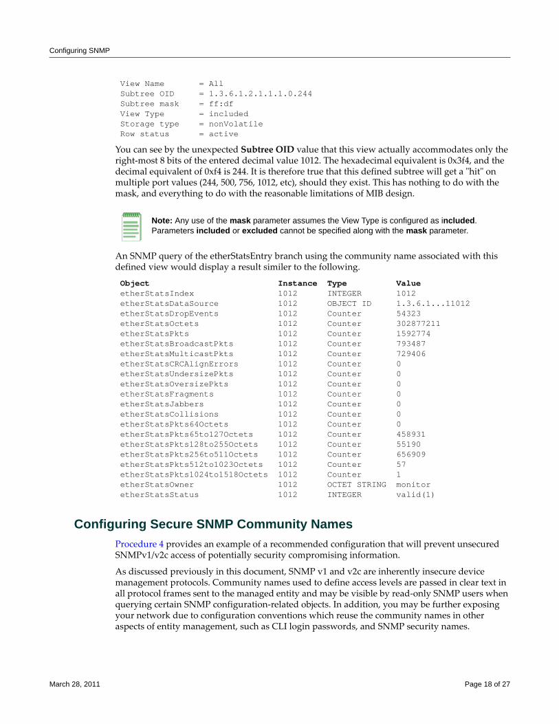
Configuring SNMP
View Name = All Subtree OID = 1.3.6.1.2.1.1.1.0.244 Subtree mask = ff:df View Type = included Storage type = nonVolatile Row status = active
You can see by the unexpected Subtree OID value that this view actually accommodates only the right‐most 8 bits of the entered decimal value 1012. The hexadecimal equivalent is 0x3f4, and the decimal equivalent of 0xf4 is 244. It is therefore true that this defined subtree will get a ʺhitʺ on multiple port values (244, 500, 756, 1012, etc), should they exist. This has nothing to do with the mask, and everything to do with the reasonable limitations of MIB design.
An SNMP query of the etherStatsEntry branch using the community name associated with this defined view would display a result similer to the following.
Object Instance Type Value etherStatsIndex 1012 INTEGER 1012 etherStatsDataSource 1012 OBJECT ID 1.3.6.1...11012 etherStatsDropEvents 1012 Counter 54323 etherStatsOctets 1012 Counter 302877211 etherStatsPkts 1012 Counter 1592774 etherStatsBroadcastPkts 1012 Counter 793487 etherStatsMulticastPkts 1012 Counter 729406 etherStatsCRCAlignErrors 1012 Counter 0 etherStatsUndersizePkts 1012 Counter 0 etherStatsOversizePkts 1012 Counter 0 etherStatsFragments 1012 Counter 0 etherStatsJabbers 1012 Counter 0 etherStatsCollisions 1012 Counter 0 etherStatsPkts64Octets 1012 Counter 0 etherStatsPkts65to127Octets 1012 Counter 458931 etherStatsPkts128to255Octets 1012 Counter 55190 etherStatsPkts256to511Octets 1012 Counter 656909 etherStatsPkts512to1023Octets 1012 Counter 57 etherStatsPkts1024to1518Octets 1012 Counter 1 etherStatsOwner 1012 OCTET STRING monitor etherStatsStatus 1012 INTEGER valid(1)
Configuring Secure SNMP Community NamesProcedure 4 provides an example of a recommended configuration that will prevent unsecured SNMPv1/v2c access of potentially security compromising information.
As discussed previously in this document, SNMP v1 and v2c are inherently insecure device management protocols. Community names used to define access levels are passed in clear text in all protocol frames sent to the managed entity and may be visible by read‐only SNMP users when querying certain SNMP configuration‐related objects. In addition, you may be further exposing your network due to configuration conventions which reuse the community names in other aspects of entity management, such as CLI login passwords, and SNMP security names.
Note: Any use of the mask parameter assumes the View Type is configured as included. Parameters included or excluded cannot be specified along with the mask parameter.
March 28, 2011 Page 18 of 27
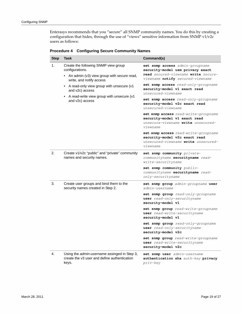
Configuring SNMP
Enterasys recommends that you “secure” all SNMP community names. You do this by creating a configuration that hides, through the use of “views” sensitive information from SNMP v1/v2c users as follows:
Procedure 4 Configuring Secure Community Names
Step Task Command(s)
1. Create the following SNMP view group configurations.
• An admin (v3) view group with secure read, write, and notify access
• A read-only view group with unsecure (v1 and v2c) access
• A read-write view group with unsecure (v1 and v2c) access
set snmp access admin-groupname security-model usm privacy exact read secured-viewname write secure-viewname notify secured-viewname
set snmp access read-only-groupname security-model v1 exact read unsecured-viewname
set snmp access read-only-groupname security-model v2c exact read unsecured-viewname
set snmp access read-write-groupname security-model v1 exact read unsecure-viewname write unsecured-viewname
set snmp access read-write-groupname security-model v2c exact read unsecured-viewname write unsecured-viewname
2. Create v1/v2c “public” and “private” community names and security names.
set snmp community private-communityname securityname read-write-securityname
set snmp community public-communityname securityname read-only-securityname
3. Create user groups and bind them to the security names created in Step 2.
set snmp group admin-groupname user admin-username
set snmp group read-only-groupname user read-only-securityname security-model v1
set snmp group read-write-groupname user read-write-securityname security-model v1
set snmp group read-only-groupname user read-only-securityname security-model v2c
set snmp group read-write-groupname user read-write-securityname security-model v2c
4. Using the admin-username assinged in Step 3, create the v3 user and define authentication keys.
set snmp user admin-username authentication sha auth-key privacy priv-key
March 28, 2011 Page 19 of 27
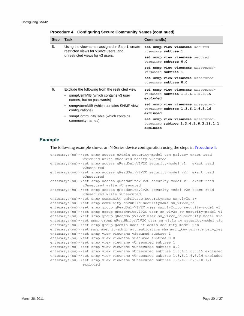
Configuring SNMP
ExampleThe following example shows an N‐Series device configuration using the steps in Procedure 4.
enterasys(su)->set snmp access gAdmin security-model usm privacy exact read vSecured write vSecured notify vSecuredenterasys(su)->set snmp access gReadOnlyV1V2C security-model v1 exact read vUnsecuredenterasys(su)->set snmp access gReadOnlyV1V2C security-model v2c exact read vUnsecuredenterasys(su)->set snmp access gReadWriteV1V2C security-model v1 exact read vUnsecured write vUnsecuredenterasys(su)->set snmp access gReadWriteV1V2C security-model v2c exact read vUnsecured write vUnsecuredenterasys(su)->set snmp community cnPrivate securityname sn_v1v2c_rwenterasys(su)->set snmp community cnPublic securityname sn_v1v2c_roenterasys(su)->set snmp group gReadOnlyV1V2C user sn_v1v2c_ro security-model v1enterasys(su)->set snmp group gReadWriteV1V2C user sn_v1v2c_rw security-model v1enterasys(su)->set snmp group gReadOnlyV1V2C user sn_v1v2c_ro security-model v2centerasys(su)->set snmp group gReadWriteV1V2C user sn_v1v2c_rw security-model v2centerasys(su)->set snmp group gAdmin user it-admin security-model usmenterasys(su)->set snmp user it-admin authentication sha auth_key privacy priv_keyenterasys(su)->set snmp view viewname vSecured subtree 1enterasys(su)->set snmp view viewname vSecured subtree 0.0enterasys(su)->set snmp view viewname vUnsecured subtree 1enterasys(su)->set snmp view viewname vUnsecured subtree 0.0enterasys(su)->set snmp view viewname vUnsecured subtree 1.3.6.1.6.3.15 excludedenterasys(su)->set snmp view viewname vUnsecured subtree 1.3.6.1.6.3.16 excludedenterasys(su)->set snmp view viewname vUnsecured subtree 1.3.6.1.6.3.18.1.1 excluded
5. Using the viewnames assigned in Step 1, create restricted views for v1/v2c users, and unrestricted views for v3 users.
set snmp view viewname secured-viewname subtree 1
set snmp view viewname secured-viewname subtree 0.0
set snmp view viewname unsecured-viewname subtree 1
set snmp view viewname unsecured-viewname subtree 0.0
6. Exclude the following from the restricted view
• snmpUsmMIB (which contains v3 user names, but no passwords)
• snmpVacmMIB (which contains SNMP view configurations)
• snmpCommunityTable (which contains community names)
set snmp view viewname unsecured-viewname subtree 1.3.6.1.6.3.15 excluded
set snmp view viewname unsecured-viewname subtree 1.3.6.1.6.3.16 excluded
set snmp view viewname unsecured-viewname subtree 1.3.6.1.6.3.18.1.1 excluded
Procedure 4 Configuring Secure Community Names (continued)
Step Task Command(s)
March 28, 2011 Page 20 of 27
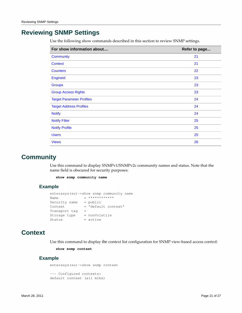
Reviewing SNMP Settings
Reviewing SNMP SettingsUse the following show commands described in this section to review SNMP settings.
CommunityUse this command to display SNMPv1/SNMPv2c community names and status. Note that the name field is obscured for security purposes:
show snmp community name
Exampleenterasys(su)->show snmp community nameName = ************Security name = public Context = “default context”Transport tag = Storage type = nonVolatile Status = active
ContextUse this command to display the context list configuration for SNMP view‐based access control:
show snmp context
Exampleenterasys(su)->show snmp context --- Configured contexts: default context (all mibs)
For show information about.... Refer to page...
Community 21
Context 21
Counters 22
Engineid 23
Groups 23
Group Access Rights 23
Target Parameter Profiles 24
Target Address Profiles 24
Notify 24
Notify Filter 25
Notify Profile 25
Users 25
Views 26
March 28, 2011 Page 21 of 27
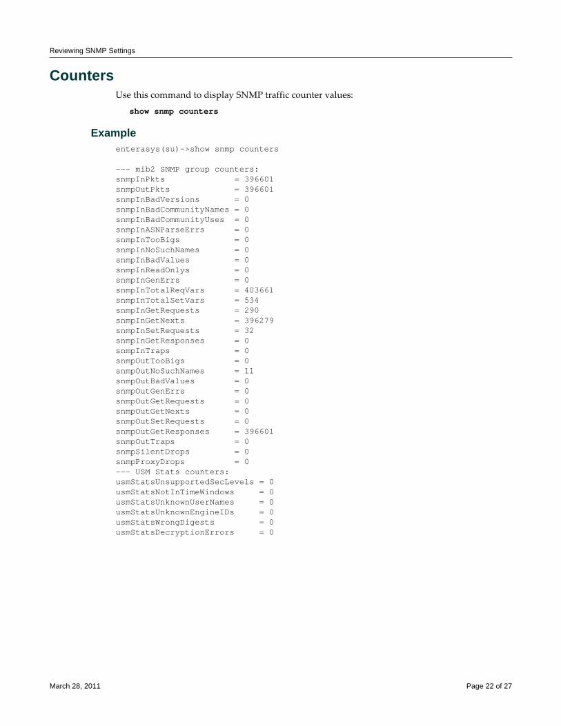
Reviewing SNMP Settings
CountersUse this command to display SNMP traffic counter values:
show snmp counters
Exampleenterasys(su)->show snmp counters
--- mib2 SNMP group counters: snmpInPkts = 396601 snmpOutPkts = 396601 snmpInBadVersions = 0 snmpInBadCommunityNames = 0 snmpInBadCommunityUses = 0 snmpInASNParseErrs = 0 snmpInTooBigs = 0 snmpInNoSuchNames = 0 snmpInBadValues = 0 snmpInReadOnlys = 0 snmpInGenErrs = 0 snmpInTotalReqVars = 403661 snmpInTotalSetVars = 534 snmpInGetRequests = 290 snmpInGetNexts = 396279 snmpInSetRequests = 32 snmpInGetResponses = 0 snmpInTraps = 0 snmpOutTooBigs = 0 snmpOutNoSuchNames = 11 snmpOutBadValues = 0 snmpOutGenErrs = 0 snmpOutGetRequests = 0 snmpOutGetNexts = 0 snmpOutSetRequests = 0 snmpOutGetResponses = 396601 snmpOutTraps = 0 snmpSilentDrops = 0 snmpProxyDrops = 0 --- USM Stats counters: usmStatsUnsupportedSecLevels = 0 usmStatsNotInTimeWindows = 0 usmStatsUnknownUserNames = 0 usmStatsUnknownEngineIDs = 0 usmStatsWrongDigests = 0 usmStatsDecryptionErrors = 0
March 28, 2011 Page 22 of 27
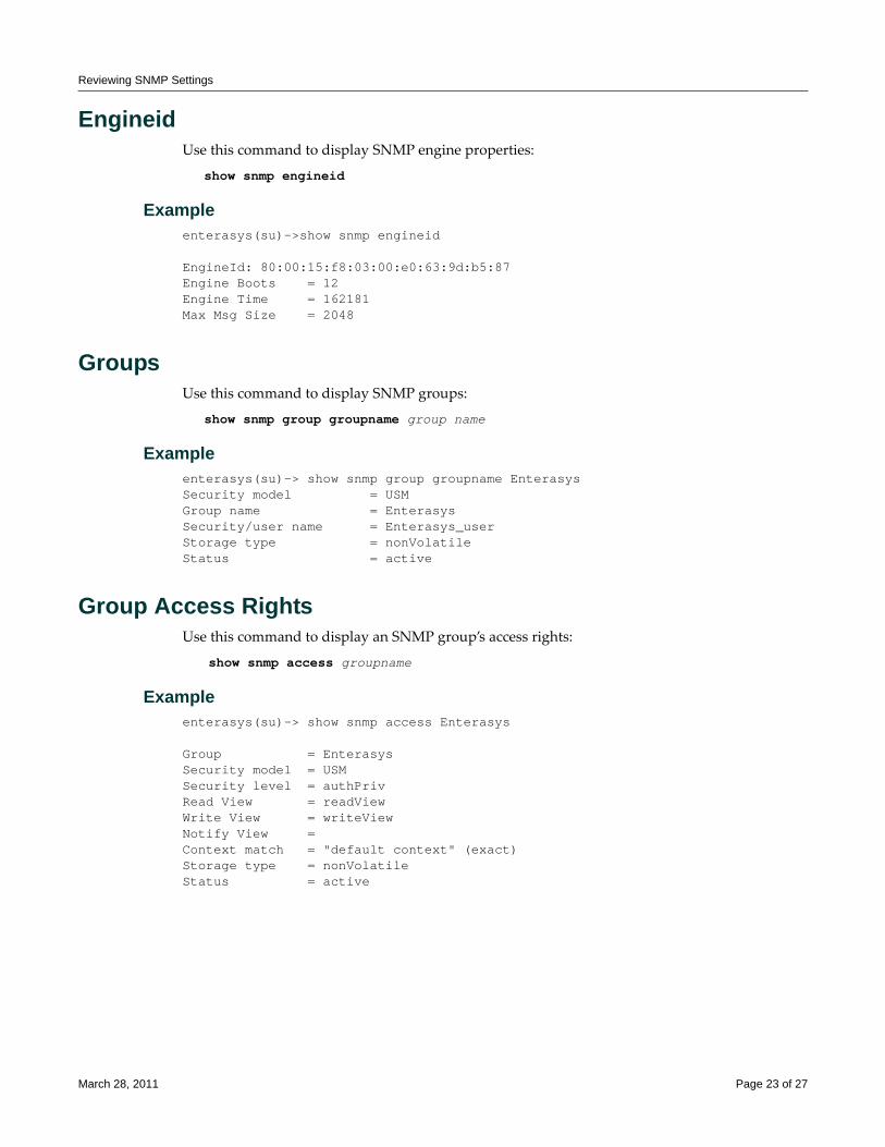
Reviewing SNMP Settings
EngineidUse this command to display SNMP engine properties:
show snmp engineid
Exampleenterasys(su)->show snmp engineid
EngineId: 80:00:15:f8:03:00:e0:63:9d:b5:87Engine Boots = 12 Engine Time = 162181 Max Msg Size = 2048
GroupsUse this command to display SNMP groups:
show snmp group groupname group name
Exampleenterasys(su)-> show snmp group groupname EnterasysSecurity model = USMGroup name = Enterasys Security/user name = Enterasys_userStorage type = nonVolatileStatus xxxxxxx = active
Group Access RightsUse this command to display an SNMP group’s access rights:
show snmp access groupname
Exampleenterasys(su)-> show snmp access Enterasys
Group = EnterasysSecurity model = USMSecurity level = authPrivRead View = readViewWrite View = writeViewNotify View =Context match = "default context" (exact)Storage type = nonVolatileStatus xxxxxxxxx= active
March 28, 2011 Page 23 of 27
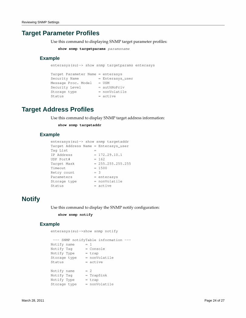
Reviewing SNMP Settings
Target Parameter ProfilesUse this command to displaying SNMP target parameter profiles:
show snmp targetparams paramsname
Exampleenterasys(su)-> show snmp targetparams enterasys
Target Parameter Name = enterasysSecurity Name = Enterasys_userMessage Proc. Model = USMSecurity Level = authNoPrivStorage type = nonVolatileStatus xxxx = active
Target Address ProfilesUse this command to display SNMP target address information:
show snmp targetaddr
Exampleenterasys(su)-> show snmp targetaddrTarget Address Name = Enterasys_userTag List = IP Address = 172.29.10.1UDP Port# = 162Target Mask = 255.255.255.255Timeout = 1500Retry count = 3Parameters = enterasysStorage type = nonVolatileStatus xxxx = active
NotifyUse this command to display the SNMP notify configuration:
show snmp notify
Exampleenterasys(su)->show snmp notify --- SNMP notifyTable information --- Notify name = 1 Notify Tag = Console Notify Type = trap Storage type = nonVolatile Status xxxxx = active
Notify name = 2 Notify Tag = TrapSink Notify Type = trap Storage type = nonVolatile
March 28, 2011 Page 24 of 27
Reviewing SNMP Settings
Status xxxxx = active
Notify FilterUse this command to display SNMP notify filter information, identifying which profiles will not receive SNMP notifications:
show snmp notifyfilter [profile] [subtree oid-or-mibobject] [volatile | nonvolatile]
Exampleenterasys(su)->show snmp notifyfilter
--- SNMP notifyFilter information ---Profile = pilot1Subtree = 1.3.6Subtree maskFilter type = includedStorage type = nonVolatileStatus xxxxx = active
Notify ProfileUse this command to display SNMP notify profile information:
show snmp notifyprofile [profile] [targetparam targetparam] [volatile | nonvolatile]
Exampleenterasys(su)->show snmp notifyprofile area51
--- SNMP notifyProfile information ---Notify Profile = area51TargetParam = v3ExampleParamsStorage type = nonVolatileStatus xxxxx = active
UsersUse this command to isplay SNMPv3 users:
show snmp user user
Exampleenterasys(su)->show snmp user Enterasys_user
EngineId xxxxxxxxxxxxxxx= 80:00:15:f8:03:00:e0:63:9d:cb:89Username = Enterasys_userAuth protocol = usmHMACMD5AuthProtocolPrivacy protocol = usmDESPrivProtocolStorage type = nonVolatileStatus xxxxxxxxxxxxxxxxx= active
March 28, 2011 Page 25 of 27
Reviewing SNMP Settings
ViewsUse this command to display SNMP views:
show snmp view viewname
Exampleenterasys(su)->show snmp view readView
View Name = readViewSubtree OID = 1Subtree mask =View Type = includedStorage type = nonVolatileStatus xxxx= active
March 28, 2011 Page 26 of 27
Enterasys Networks reserves the right to make changes in specifications and other information contained in this document and its web site without prior notice. The reader should in all cases consult Enterasys Networks to determine whether any such changes have been made.
The hardware, firmware, or software described in this document is subject to change without notice.
IN NO EVENT SHALL ENTERASYS NETWORKS BE LIABLE FOR ANY INCIDENTAL, INDIRECT, SPECIAL, OR CONSEQUENTIAL DAMAGES WHATSOEVER (INCLUDING BUT NOT LIMITED TO LOST PROFITS) ARISING OUT OF OR RELATED TO THIS DOCUMENT, WEB SITE, OR THE INFORMATION CONTAINED IN THEM, EVEN IF ENTERASYS NETWORKS HAS BEEN ADVISED OF, KNEW OF, OR SHOULD HAVE KNOWN OF, THE POSSIBILITY OF SUCH DAMAGES.
Enterasys Networks, Inc.50 Minuteman RoadAndover, MA 01810
© 2011 Enterasys Networks, Inc. All rights reserved.
ENTERASYS, ENTERASYS NETWORKS, ENTERASYS NETSIGHT, and any logos associated therewith, are trademarks or registered trademarks of Enterasys Networks, Inc., in the United States and other countries. For a complete list of Enterasys trademarks, see http://www.enterasys.com/company/trademarks.aspx.
All other product names mentioned in this manual may be trademarks or registered trademarks of their respective companies.
Revision History
Date Description
05-30-08 New document.
07-28-08 Added Enterasys registration mark.
12-08-08 Made minor edits.
03-28-2011 Updated to include S-Series, K-Series, and minor terminiology changes.
Configuring Spanning Trees
This document provides the following information about configuring and monitoring Spanning Tree protocols on Enterasys® N‐Series, S‐Series, and K‐Series modular switches, A‐Series, B‐Series, C‐Series stackable fixed switches, and D‐Series, G‐Series, and I‐Series standalone fixed switches.
What Is the Spanning Tree Protocol?The Spanning Tree Protocol (STP) resolves the problems of physical loops in a network by establishing one primary path between any two devices. Duplicate paths are barred from use and become standby or blocked paths until the original path fails, at which point duplicate paths can be brought into service. Should a bridge be added creating a redundant path, STP blocks one of the paths. Basically, the “tree” in the Spanning Tree Protocol is the optimal branching of network paths that STP‐enabled devices keep in memory for efficient and fault‐tolerant data forwarding.
Why Would I Use Spanning Trees in My Network?Redundant links must be factored into even the simplest of topologies to protect against data loss and downtime due to any single point of failure. However, redundant links can also set an endless loop in motion, significantly stressing your network’s speed and efficiency. As shown in Figure 1, a planned redundant link between Switch 1 and Switch 2 makes it possible for a bridging loop to occur. If Station 1 transmits a multicast or broadcast packet to Station 2 in this scenario, the packet
For information about... Refer to page...
What Is the Spanning Tree Protocol? 1
Why Would I Use Spanning Trees in My Network? 1
How Do I Implement Spanning Trees? 2
STP Overview 2
Functions and Features Supported on Enterasys Devices 4
Understanding How Spanning Tree Operates 6
Configuring STP and RSTP 11
Configuring MSTP 18
Understanding and Configuring SpanGuard 20
Understanding and Configuring Loop Protect 22
Terms and Definitions 27
Note: For information about configuring Spanning Tree on the X-Series, refer to the X-Series Configuration Guide.
March 14, 2011 Page 1 of 29
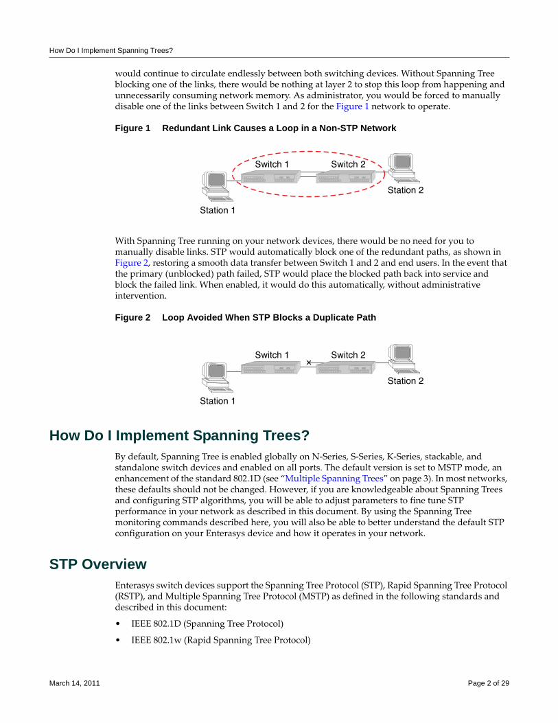
How Do I Implement Spanning Trees?
would continue to circulate endlessly between both switching devices. Without Spanning Tree blocking one of the links, there would be nothing at layer 2 to stop this loop from happening and unnecessarily consuming network memory. As administrator, you would be forced to manually disable one of the links between Switch 1 and 2 for the Figure 1 network to operate.
Figure 1 Redundant Link Causes a Loop in a Non-STP Network
With Spanning Tree running on your network devices, there would be no need for you to manually disable links. STP would automatically block one of the redundant paths, as shown in Figure 2, restoring a smooth data transfer between Switch 1 and 2 and end users. In the event that the primary (unblocked) path failed, STP would place the blocked path back into service and block the failed link. When enabled, it would do this automatically, without administrative intervention.
Figure 2 Loop Avoided When STP Blocks a Duplicate Path
How Do I Implement Spanning Trees?By default, Spanning Tree is enabled globally on N‐Series, S‐Series, K‐Series, stackable, and standalone switch devices and enabled on all ports. The default version is set to MSTP mode, an enhancement of the standard 802.1D (see “Multiple Spanning Trees” on page 3). In most networks, these defaults should not be changed. However, if you are knowledgeable about Spanning Trees and configuring STP algorithms, you will be able to adjust parameters to fine tune STP performance in your network as described in this document. By using the Spanning Tree monitoring commands described here, you will also be able to better understand the default STP configuration on your Enterasys device and how it operates in your network.
STP OverviewEnterasys switch devices support the Spanning Tree Protocol (STP), Rapid Spanning Tree Protocol (RSTP), and Multiple Spanning Tree Protocol (MSTP) as defined in the following standards and described in this document:
• IEEE 802.1D (Spanning Tree Protocol)
• IEEE 802.1w (Rapid Spanning Tree Protocol)
March 14, 2011 Page 2 of 29
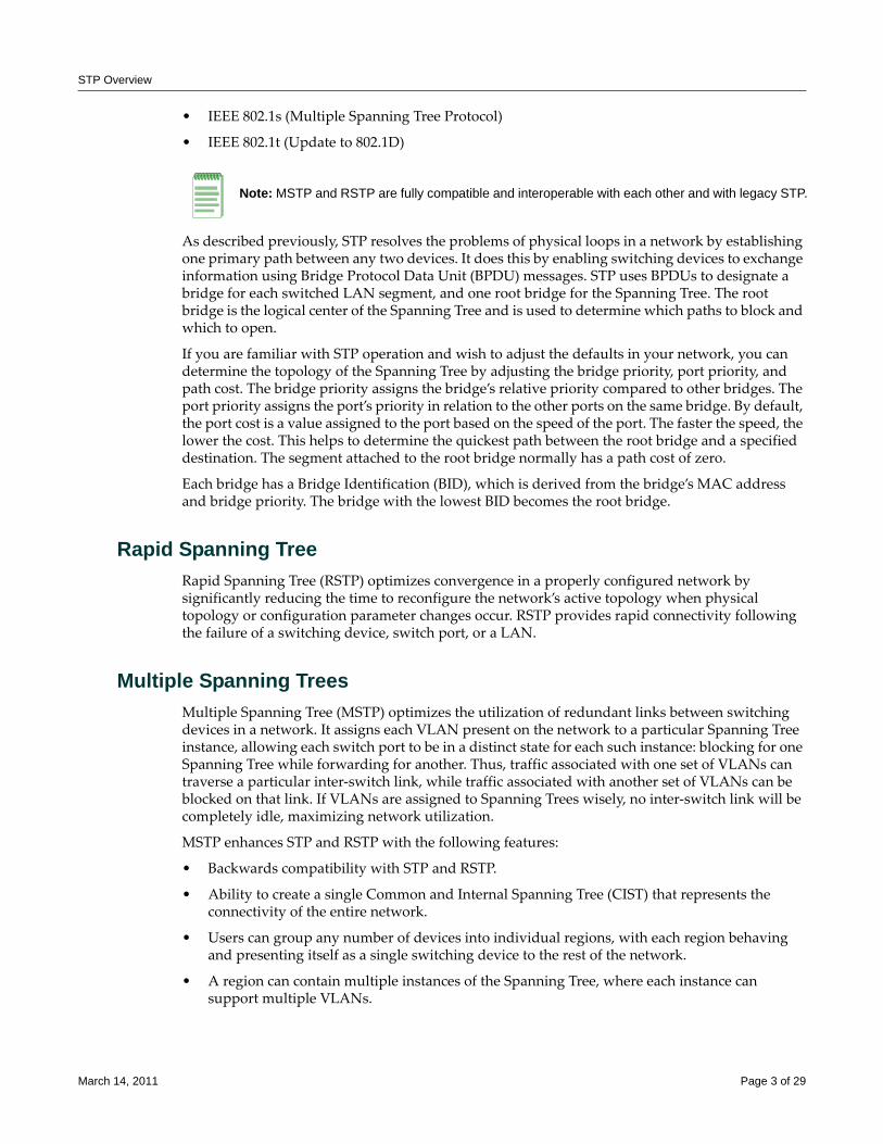
STP Overview
• IEEE 802.1s (Multiple Spanning Tree Protocol)
• IEEE 802.1t (Update to 802.1D)
As described previously, STP resolves the problems of physical loops in a network by establishing one primary path between any two devices. It does this by enabling switching devices to exchange information using Bridge Protocol Data Unit (BPDU) messages. STP uses BPDUs to designate a bridge for each switched LAN segment, and one root bridge for the Spanning Tree. The root bridge is the logical center of the Spanning Tree and is used to determine which paths to block and which to open.
If you are familiar with STP operation and wish to adjust the defaults in your network, you can determine the topology of the Spanning Tree by adjusting the bridge priority, port priority, and path cost. The bridge priority assigns the bridge’s relative priority compared to other bridges. The port priority assigns the port’s priority in relation to the other ports on the same bridge. By default, the port cost is a value assigned to the port based on the speed of the port. The faster the speed, the lower the cost. This helps to determine the quickest path between the root bridge and a specified destination. The segment attached to the root bridge normally has a path cost of zero.
Each bridge has a Bridge Identification (BID), which is derived from the bridge’s MAC address and bridge priority. The bridge with the lowest BID becomes the root bridge.
Rapid Spanning TreeRapid Spanning Tree (RSTP) optimizes convergence in a properly configured network by significantly reducing the time to reconfigure the network’s active topology when physical topology or configuration parameter changes occur. RSTP provides rapid connectivity following the failure of a switching device, switch port, or a LAN.
Multiple Spanning Trees Multiple Spanning Tree (MSTP) optimizes the utilization of redundant links between switching devices in a network. It assigns each VLAN present on the network to a particular Spanning Tree instance, allowing each switch port to be in a distinct state for each such instance: blocking for one Spanning Tree while forwarding for another. Thus, traffic associated with one set of VLANs can traverse a particular inter‐switch link, while traffic associated with another set of VLANs can be blocked on that link. If VLANs are assigned to Spanning Trees wisely, no inter‐switch link will be completely idle, maximizing network utilization.
MSTP enhances STP and RSTP with the following features:
• Backwards compatibility with STP and RSTP.
• Ability to create a single Common and Internal Spanning Tree (CIST) that represents the connectivity of the entire network.
• Users can group any number of devices into individual regions, with each region behaving and presenting itself as a single switching device to the rest of the network.
• A region can contain multiple instances of the Spanning Tree, where each instance can support multiple VLANs.
Note: MSTP and RSTP are fully compatible and interoperable with each other and with legacy STP.
March 14, 2011 Page 3 of 29
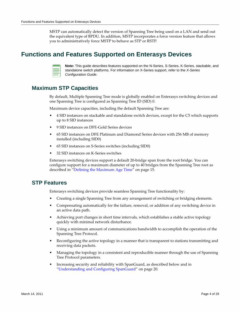
Functions and Features Supported on Enterasys Devices
MSTP can automatically detect the version of Spanning Tree being used on a LAN and send out the equivalent type of BPDU. In addition, MSTP incorporates a force version feature that allows you to administratively force MSTP to behave as STP or RSTP.
Functions and Features Supported on Enterasys Devices
Maximum STP CapacitiesBy default, Multiple Spanning Tree mode is globally enabled on Enterasys switching devices and one Spanning Tree is configured as Spanning Tree ID (SID) 0.
Maximum device capacities, including the default Spanning Tree are:
• 4 SID instances on stackable and standalone switch devices, except for the C5 which supports up to 8 SID instances
• 9 SID instances on DFE‐Gold Series devices
• 65 SID instances on DFE Platinum and Diamond Series devices with 256 MB of memory installed (including SID0)
• 65 SID instances on S‐Series switches (including SID0)
• 32 SID instances on K‐Series switches
Enterasys switching devices support a default 20‐bridge span from the root bridge. You can configure support for a maximum diameter of up to 40 bridges from the Spanning Tree root as described in “Defining the Maximum Age Time” on page 15.
STP FeaturesEnterasys switching devices provide seamless Spanning Tree functionality by:
• Creating a single Spanning Tree from any arrangement of switching or bridging elements.
• Compensating automatically for the failure, removal, or addition of any switching device in an active data path.
• Achieving port changes in short time intervals, which establishes a stable active topology quickly with minimal network disturbance.
• Using a minimum amount of communications bandwidth to accomplish the operation of the Spanning Tree Protocol.
• Reconfiguring the active topology in a manner that is transparent to stations transmitting and receiving data packets.
• Managing the topology in a consistent and reproducible manner through the use of Spanning Tree Protocol parameters.
• Increasing security and reliability with SpanGuard, as described below and in “Understanding and Configuring SpanGuard” on page 20.
Note: This guide describes features supported on the N-Series, S-Series, K-Series, stackable, and standalone switch platforms. For information on X-Series support, refer to the X-Series Configuration Guide.
March 14, 2011 Page 4 of 29
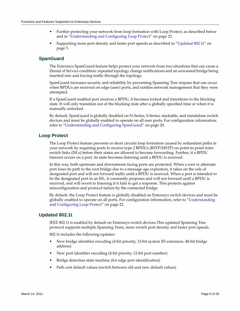
Functions and Features Supported on Enterasys Devices
• Further protecting your network from loop formation with Loop Protect, as described below and in “Understanding and Configuring Loop Protect” on page 22.
• Supporting more port density and faster port speeds as described in “Updated 802.1t” on page 5.
SpanGuardThe Enterasys SpanGuard feature helps protect your network from two situations that can cause a Denial of Service condition: repeated topology change notifications and an unwanted bridge being inserted into and forcing traffic through the topology.
SpanGuard increases security and reliability by preventing Spanning Tree respans that can occur when BPDUs are received on edge (user) ports, and notifies network management that they were attempted.
If a SpanGuard enabled port receives a BPDU, it becomes locked and transitions to the blocking state. It will only transition out of the blocking state after a globally specified time or when it is manually unlocked.
By default, SpanGuard is globally disabled on N‐Series, S‐Series, stackable, and standalone switch devices and must be globally enabled to operate on all user ports. For configuration information, refer to “Understanding and Configuring SpanGuard” on page 20.
Loop ProtectThe Loop Protect feature prevents or short circuits loop formation caused by redundant paths in your network by requiring ports to receive type 2 BPDUs (RSTP/MSTP) on point‐to‐point inter‐switch links (ISLs) before their states are allowed to become forwarding. Further, if a BPDU timeout occurs on a port, its state becomes listening until a BPDU is received.
In this way, both upstream and downstream facing ports are protected. When a root or alternate port loses its path to the root bridge due to a message age expiration, it takes on the role of designated port and will not forward traffic until a BPDU is received. When a port is intended to be the designated port in an ISL, it constantly proposes and will not forward until a BPDU is received, and will revert to listening if it fails to get a response. This protects against misconfiguration and protocol failure by the connected bridge.
By default, the Loop Protect feature is globally disabled on Enterasys switch devices and must be globally enabled to operate on all ports. For configuration information, refer to “Understanding and Configuring Loop Protect” on page 22.
Updated 802.1tIEEE 802.1t is enabled by default on Enterasys switch devices.This updated Spanning Tree protocol supports multiple Spanning Trees, more switch port density and faster port speeds.
802.1t includes the following updates:
• New bridge identifier encoding (4‐bit priority, 12‐bit system ID extension, 48‐bit bridge address)
• New port identifier encoding (4‐bit priority, 12‐bit port number)
• Bridge detection state machine (for edge port identification)
• Path cost default values (switch between old and new default values)
March 14, 2011 Page 5 of 29
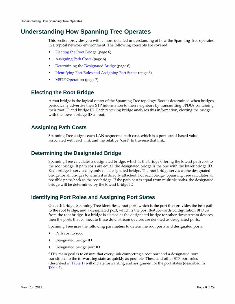
Understanding How Spanning Tree Operates
Understanding How Spanning Tree OperatesThis section provides you with a more detailed understanding of how the Spanning Tree operates in a typical network environment. The following concepts are covered.
• Electing the Root Bridge (page 6)
• Assigning Path Costs (page 6)
• Determining the Designated Bridge (page 6)
• Identifying Port Roles and Assigning Port States (page 6)
• MSTP Operation (page 7)
Electing the Root BridgeA root bridge is the logical center of the Spanning Tree topology. Root is determined when bridges periodically advertise their STP information to their neighbors by transmitting BPDUs containing their root ID and bridge ID. Each receiving bridge analyzes this information, electing the bridge with the lowest bridge ID as root.
Assigning Path CostsSpanning Tree assigns each LAN segment a path cost, which is a port speed‐based value associated with each link and the relative “cost” to traverse that link.
Determining the Designated BridgeSpanning Tree calculates a designated bridge, which is the bridge offering the lowest path cost to the root bridge. If path costs are equal, the designated bridge is the one with the lower bridge ID. Each bridge is serviced by only one designated bridge. The root bridge serves as the designated bridge for all bridges to which it is directly attached. For each bridge, Spanning Tree calculates all possible paths back to the root bridge. If the path cost is equal from multiple paths, the designated bridge will be determined by the lowest bridge ID.
Identifying Port Roles and Assigning Port StatesOn each bridge, Spanning Tree identifies a root port, which is the port that provides the best path to the root bridge, and a designated port, which is the port that forwards configuration BPDUs from the root bridge. If a bridge is elected as the designated bridge for other downstream devices, then the ports that connect to these downstream devices are denoted as designated ports.
Spanning Tree uses the following parameters to determine root ports and designated ports:
• Path cost to root
• Designated bridge ID
• Designated bridge port ID
STP’s main goal is to ensure that every link connecting a root port and a designated port transitions to the forwarding state as quickly as possible. These and other STP port roles (described in Table 1) will dictate forwarding and assignment of the port states (described in Table 2).
March 14, 2011 Page 6 of 29
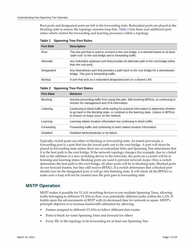
Understanding How Spanning Tree Operates
Root ports and designated ports are left in the forwarding state. Redundant ports are placed in the blocking state to ensure the topology remains loop‐free. Table 2 lists these and additional port states which control the forwarding and learning processes within a topology.
Typically, switch ports are either in blocking or forwarding state. As stated previously, a forwarding port is a port that has the lowest path cost to the root bridge. A port will never be placed in forwarding state unless there are no redundant links and Spanning Tree determines that it is the best path to the root bridge. If the network topology changes (for example, due to a failed link or the addition of a new switching device to the network), the ports on a switch will be in listening and learning states. Blocking ports are used to prevent network loops. Once a switch determines the best path to the root bridge, all other ports will be in blocking state. Blocked ports do not forward frames, but they still receive BPDUs. If a switch determines that a blocked port should now be the designated port, it will go into listening state. It will check all the BPDUs to make sure a loop will not be created once the port goes to forwarding state.
MSTP OperationMSTP makes it possible for VLAN switching devices to use multiple Spanning Trees, allowing traffic belonging to different VLANs to flow over potentially different paths within the LAN. It builds upon the advancements of RSTP with its decreased time for network re‐spans. MSTP’s principle objective is to increase bandwidth utilization by allowing:
• Frames assigned to different VLANs to follow different data routes
• Ports to block for some Spanning Trees and forward for others
• Every ISL in the topology to be forwarding for at least one Spanning Tree
Table 1 Spanning Tree Port RolesPort Role Description
Root The one port that is used to connect to the root bridge. It is elected based on its least “path-cost” to the root bridge and is forwarding traffic.
Alternate Any redundant upstream port that provides an alternate path to the root bridge (other than the root port).
Designated Any downstream port that provides a path back to the root bridge for a downstream bridge. This port is forwarding traffic.
Backup A port that acts as a redundant designated port on a shared LAN.
Table 2 Spanning Tree Port StatesPort State Behavior
Blocking Actively preventing traffic from using this path. Still receiving BPDUs, so continuing to monitor for management and STA information.
Listening Continuing to block traffic while waiting for protocol information to determine whether to go back to the blocking state, or continue to the learning state. Listens to BPDUs to ensure no loops occur on the network.
Learning Learning station location information but continuing to block traffic.
Forwarding Forwarding traffic and continuing to learn station location information.
Disabled Disabled administratively or by failure.
March 14, 2011 Page 7 of 29
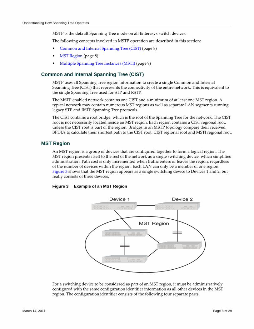
Understanding How Spanning Tree Operates
MSTP is the default Spanning Tree mode on all Enterasys switch devices.
The following concepts involved in MSTP operation are described in this section:
• Common and Internal Spanning Tree (CIST) (page 8)
• MST Region (page 8)
• Multiple Spanning Tree Instances (MSTI) (page 9)
Common and Internal Spanning Tree (CIST)MSTP uses all Spanning Tree region information to create a single Common and Internal Spanning Tree (CIST) that represents the connectivity of the entire network. This is equivalent to the single Spanning Tree used for STP and RSTP.
The MSTP enabled network contains one CIST and a minimum of at least one MST region. A typical network may contain numerous MST regions as well as separate LAN segments running legacy STP and RSTP Spanning Tree protocols.
The CIST contains a root bridge, which is the root of the Spanning Tree for the network. The CIST root is not necessarily located inside an MST region. Each region contains a CIST regional root, unless the CIST root is part of the region. Bridges in an MSTP topology compare their received BPDUs to calculate their shortest path to the CIST root, CIST regional root and MSTI regional root.
MST RegionAn MST region is a group of devices that are configured together to form a logical region. The MST region presents itself to the rest of the network as a single switching device, which simplifies administration. Path cost is only incremented when traffic enters or leaves the region, regardless of the number of devices within the region. Each LAN can only be a member of one region. Figure 3 shows that the MST region appears as a single switching device to Devices 1 and 2, but really consists of three devices.
Figure 3 Example of an MST Region
For a switching device to be considered as part of an MST region, it must be administratively configured with the same configuration identifier information as all other devices in the MST region. The configuration identifier consists of the following four separate parts:
MST Region
Device 1 Device 2
March 14, 2011 Page 8 of 29
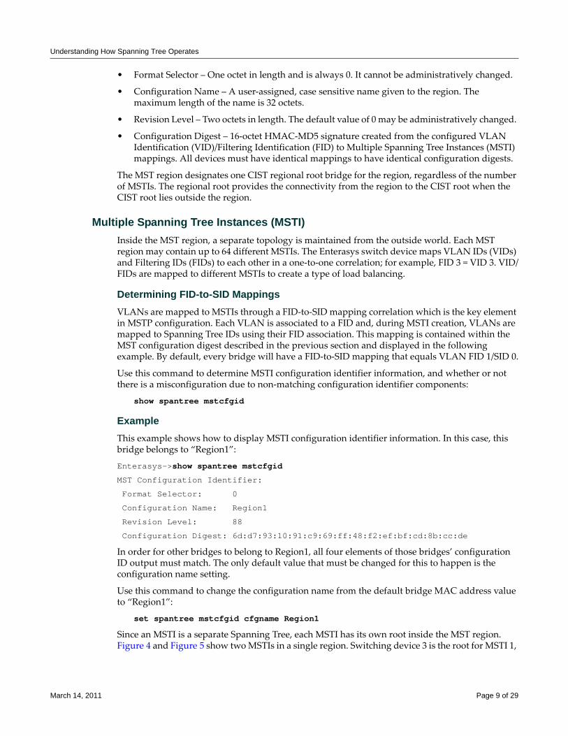
Understanding How Spanning Tree Operates
• Format Selector – One octet in length and is always 0. It cannot be administratively changed.
• Configuration Name – A user‐assigned, case sensitive name given to the region. The maximum length of the name is 32 octets.
• Revision Level – Two octets in length. The default value of 0 may be administratively changed.
• Configuration Digest – 16‐octet HMAC‐MD5 signature created from the configured VLAN Identification (VID)/Filtering Identification (FID) to Multiple Spanning Tree Instances (MSTI) mappings. All devices must have identical mappings to have identical configuration digests.
The MST region designates one CIST regional root bridge for the region, regardless of the number of MSTIs. The regional root provides the connectivity from the region to the CIST root when the CIST root lies outside the region.
Multiple Spanning Tree Instances (MSTI)Inside the MST region, a separate topology is maintained from the outside world. Each MST region may contain up to 64 different MSTIs. The Enterasys switch device maps VLAN IDs (VIDs) and Filtering IDs (FIDs) to each other in a one‐to‐one correlation; for example, FID 3 = VID 3. VID/FIDs are mapped to different MSTIs to create a type of load balancing.
Determining FID-to-SID MappingsVLANs are mapped to MSTIs through a FID‐to‐SID mapping correlation which is the key element in MSTP configuration. Each VLAN is associated to a FID and, during MSTI creation, VLANs are mapped to Spanning Tree IDs using their FID association. This mapping is contained within the MST configuration digest described in the previous section and displayed in the following example. By default, every bridge will have a FID‐to‐SID mapping that equals VLAN FID 1/SID 0.
Use this command to determine MSTI configuration identifier information, and whether or not there is a misconfiguration due to non‐matching configuration identifier components:
show spantree mstcfgid
ExampleThis example shows how to display MSTI configuration identifier information. In this case, this bridge belongs to “Region1”:
Enterasys->show spantree mstcfgid
MST Configuration Identifier:
Format Selector: 0
Configuration Name: Region1
Revision Level: 88
Configuration Digest: 6d:d7:93:10:91:c9:69:ff:48:f2:ef:bf:cd:8b:cc:de
In order for other bridges to belong to Region1, all four elements of those bridges’ configuration ID output must match. The only default value that must be changed for this to happen is the configuration name setting.
Use this command to change the configuration name from the default bridge MAC address value to “Region1”:
set spantree mstcfgid cfgname Region1
Since an MSTI is a separate Spanning Tree, each MSTI has its own root inside the MST region. Figure 4 and Figure 5 show two MSTIs in a single region. Switching device 3 is the root for MSTI 1,
March 14, 2011 Page 9 of 29
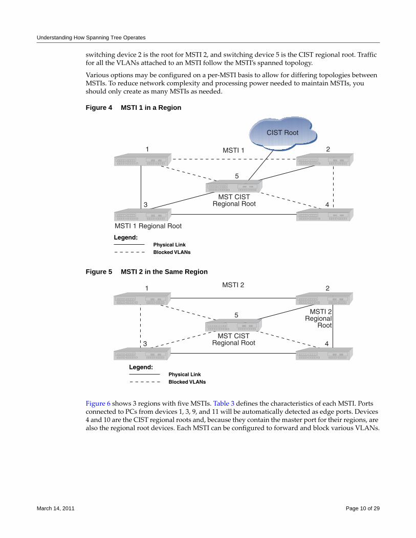
Understanding How Spanning Tree Operates
switching device 2 is the root for MSTI 2, and switching device 5 is the CIST regional root. Traffic for all the VLANs attached to an MSTI follow the MSTI’s spanned topology.
Various options may be configured on a per‐MSTI basis to allow for differing topologies between MSTIs. To reduce network complexity and processing power needed to maintain MSTIs, you should only create as many MSTIs as needed.
Figure 4 MSTI 1 in a Region
Figure 5 MSTI 2 in the Same Region
Figure 6 shows 3 regions with five MSTIs. Table 3 defines the characteristics of each MSTI. Ports connected to PCs from devices 1, 3, 9, and 11 will be automatically detected as edge ports. Devices 4 and 10 are the CIST regional roots and, because they contain the master port for their regions, are also the regional root devices. Each MSTI can be configured to forward and block various VLANs.
� �
� �
�
����
����� �������� ���
����� �������� ���
���������� �������
��� �������
��� ���
� �
� �
�
����
����� �������� ���
���� �������
���
���������� �������
��� �������
March 14, 2011 Page 10 of 29
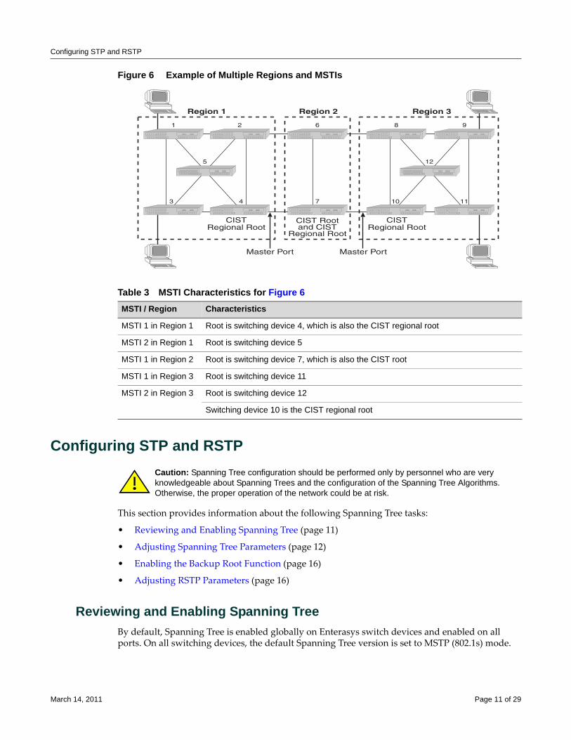
Configuring STP and RSTP
Figure 6 Example of Multiple Regions and MSTIs
Configuring STP and RSTP
This section provides information about the following Spanning Tree tasks:
• Reviewing and Enabling Spanning Tree (page 11)
• Adjusting Spanning Tree Parameters (page 12)
• Enabling the Backup Root Function (page 16)
• Adjusting RSTP Parameters (page 16)
Reviewing and Enabling Spanning TreeBy default, Spanning Tree is enabled globally on Enterasys switch devices and enabled on all ports. On all switching devices, the default Spanning Tree version is set to MSTP (802.1s) mode.
Table 3 MSTI Characteristics for Figure 6 MSTI / Region Characteristics
MSTI 1 in Region 1 Root is switching device 4, which is also the CIST regional root
MSTI 2 in Region 1 Root is switching device 5
MSTI 1 in Region 2 Root is switching device 7, which is also the CIST root
MSTI 1 in Region 3 Root is switching device 11
MSTI 2 in Region 3 Root is switching device 12
Switching device 10 is the CIST regional root
�������
� �
� �
�
�������
� �
�� ��
��
�������
�
�
������� ��� ������� ���
�� �������� ���
��� �����!���
�������� ���
�� �������� ���
Caution: Spanning Tree configuration should be performed only by personnel who are very knowledgeable about Spanning Trees and the configuration of the Spanning Tree Algorithms. Otherwise, the proper operation of the network could be at risk.
March 14, 2011 Page 11 of 29
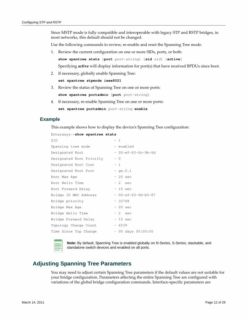
Configuring STP and RSTP
Since MSTP mode is fully compatible and interoperable with legacy STP and RSTP bridges, in most networks, this default should not be changed.
Use the following commands to review, re‐enable and reset the Spanning Tree mode.
1. Review the current configuration on one or more SIDs, ports, or both:
show spantree stats [port port-string] [sid sid] [active]
Specifying active will display information for port(s) that have received BPDUs since boot.
2. If necessary, globally enable Spanning Tree:
set spantree stpmode ieee8021
3. Review the status of Spanning Tree on one or more ports:
show spantree portadmin [port port-string]
4. If necessary, re‐enable Spanning Tree on one or more ports:
set spantree portadmin port-string enable
ExampleThis example shows how to display the device’s Spanning Tree configuration:
Enterasys->show spantree stats
SID - 1
Spanning tree mode - enabled
Designated Root - 00-e0-63-6c-9b-6d
Designated Root Priority - 0
Designated Root Cost - 1
Designated Root Port - ge.5.1
Root Max Age - 20 sec
Root Hello Time - 2 sec
Root Forward Delay - 15 sec
Bridge ID MAC Address - 00-e0-63-9d-b5-87
Bridge priority - 32768
Bridge Max Age - 20 sec
Bridge Hello Time - 2 sec
Bridge Forward Delay - 15 sec
Topology Change Count - 6539
Time Since Top Change - 00 days 00:00:00
Adjusting Spanning Tree Parameters You may need to adjust certain Spanning Tree parameters if the default values are not suitable for your bridge configuration. Parameters affecting the entire Spanning Tree are configured with variations of the global bridge configuration commands. Interface‐specific parameters are
Note: By default, Spanning Tree is enabled globally on N-Series, S-Series, stackable, and standalone switch devices and enabled on all ports.
March 14, 2011 Page 12 of 29
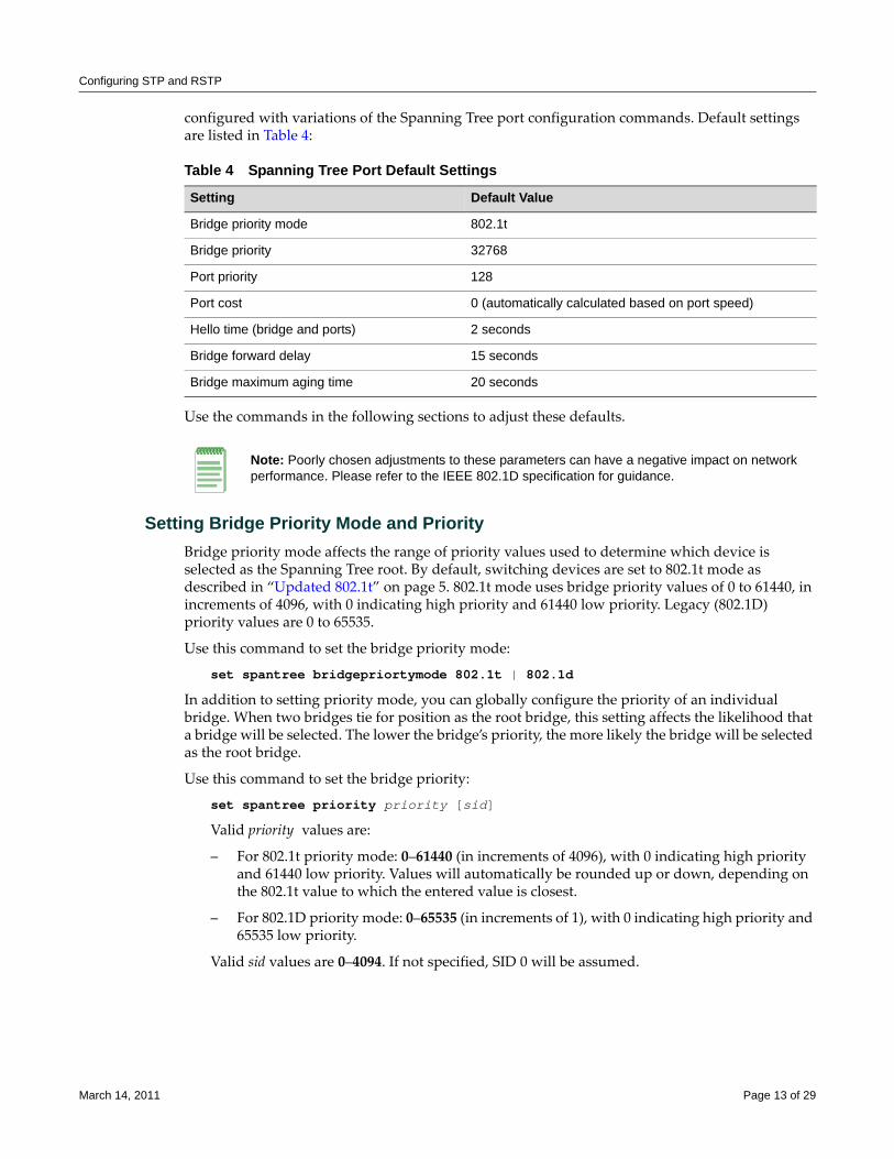
Configuring STP and RSTP
configured with variations of the Spanning Tree port configuration commands. Default settings are listed in Table 4:
Use the commands in the following sections to adjust these defaults.
Setting Bridge Priority Mode and PriorityBridge priority mode affects the range of priority values used to determine which device is selected as the Spanning Tree root. By default, switching devices are set to 802.1t mode as described in “Updated 802.1t” on page 5. 802.1t mode uses bridge priority values of 0 to 61440, in increments of 4096, with 0 indicating high priority and 61440 low priority. Legacy (802.1D) priority values are 0 to 65535.
Use this command to set the bridge priority mode:
set spantree bridgepriortymode 802.1t | 802.1d
In addition to setting priority mode, you can globally configure the priority of an individual bridge. When two bridges tie for position as the root bridge, this setting affects the likelihood that a bridge will be selected. The lower the bridge’s priority, the more likely the bridge will be selected as the root bridge.
Use this command to set the bridge priority:
set spantree priority priority [sid]
Valid priority values are:
– For 802.1t priority mode: 0–61440 (in increments of 4096), with 0 indicating high priority and 61440 low priority. Values will automatically be rounded up or down, depending on the 802.1t value to which the entered value is closest.
– For 802.1D priority mode: 0–65535 (in increments of 1), with 0 indicating high priority and 65535 low priority.
Valid sid values are 0–4094. If not specified, SID 0 will be assumed.
Table 4 Spanning Tree Port Default Settings
Setting Default Value
Bridge priority mode 802.1t
Bridge priority 32768
Port priority 128
Port cost 0 (automatically calculated based on port speed)
Hello time (bridge and ports) 2 seconds
Bridge forward delay 15 seconds
Bridge maximum aging time 20 seconds
Note: Poorly chosen adjustments to these parameters can have a negative impact on network performance. Please refer to the IEEE 802.1D specification for guidance.
March 14, 2011 Page 13 of 29
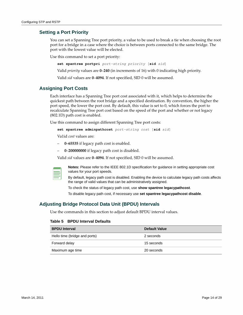
Configuring STP and RSTP
Setting a Port PriorityYou can set a Spanning Tree port priority, a value to be used to break a tie when choosing the root port for a bridge in a case where the choice is between ports connected to the same bridge. The port with the lowest value will be elected.
Use this command to set a port priority:
set spantree portpri port-string priority [sid sid]
Valid priority values are 0–240 (in increments of 16) with 0 indicating high priority.
Valid sid values are 0–4094. If not specified, SID 0 will be assumed.
Assigning Port CostsEach interface has a Spanning Tree port cost associated with it, which helps to determine the quickest path between the root bridge and a specified destination. By convention, the higher the port speed, the lower the port cost. By default, this value is set to 0, which forces the port to recalculate Spanning Tree port cost based on the speed of the port and whether or not legacy (802.1D) path cost is enabled.
Use this command to assign different Spanning Tree port costs:
set spantree adminpathcost port-string cost [sid sid]
Va1id cost values are:
– 0–65535 if legacy path cost is enabled.
– 0–200000000 if legacy path cost is disabled.
Valid sid values are 0–4094. If not specified, SID 0 will be assumed.
Adjusting Bridge Protocol Data Unit (BPDU) IntervalsUse the commands in this section to adjust default BPDU interval values.
Notes: Please refer to the IEEE 802.1D specification for guidance in setting appropriate cost values for your port speeds.
By default, legacy path cost is disabled. Enabling the device to calculate legacy path costs affects the range of valid values that can be administratively assigned.
To check the status of legacy path cost, use show spantree legacypathcost.To disable legacy path cost, if necessary use set spantree legacypathcost disable.
Table 5 BPDU Interval Defaults
BPDU Interval Default Value
Hello time (bridge and ports) 2 seconds
Forward delay 15 seconds
Maximum age time 20 seconds
March 14, 2011 Page 14 of 29
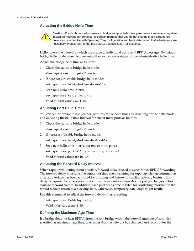
Configuring STP and RSTP
Adjusting the Bridge Hello Time
Hello time is the interval at which the bridge or individual ports send BPDU messages. By default, bridge hello mode is enabled, meaning the device uses a single bridge administrative hello time.
Adjust the bridge hello time as follows:
1. Check the status of bridge hello mode:
show spantree bridgehellomode
2. If necessary, re‐enable bridge hello mode:
set spantree bridgehellomode enable
3. Set a new hello time interval:
set spantree hello interval
Valid interval values are 1–10.
Adjusting Port Hello TimesYou can set the device to use per‐port administrative hello times by disabling bridge hello mode and adjusting the hello time interval for one or more ports as follows:
1. Check the status of bridge hello mode:
show spantree bridgehellomode
2. If necessary, disable bridge hello mode:
set spantree bridgehellomode disable
3. Set a new hello time interval for one or more ports:
set spantree porthello port-string interval
Valid interval values are 10–100
Adjusting the Forward Delay IntervalWhen rapid transitioning is not possible, forward delay is used to synchronize BPDU forwarding. The forward delay interval is the amount of time spent listening for topology change information after an interface has been activated for bridging and before forwarding actually begins. This delay is required because every device must receive information about topology changes before it starts to forward frames. In addition, each port needs time to listen for conflicting information that would make it return to a blocking state. Otherwise, temporary data loops might result.
Use this command to adjust the forward delay interval setting:
set spantree fwddelay delay
Valid delay values are 4–30.
Defining the Maximum Age TimeIf a bridge does not hear BPDUs from the root bridge within the interval (number of seconds) specified as maximum age time, it assumes that the network has changed and recomputes the
Caution: Poorly chosen adjustments to bridge and port hello time parameters can have a negative impact on network performance. It is recommended that you do not change these parameters unless you are familiar with Spanning Tree configuration and have determined that adjustments are necessary. Please refer to the IEEE 802.1D specification for guidance.
March 14, 2011 Page 15 of 29
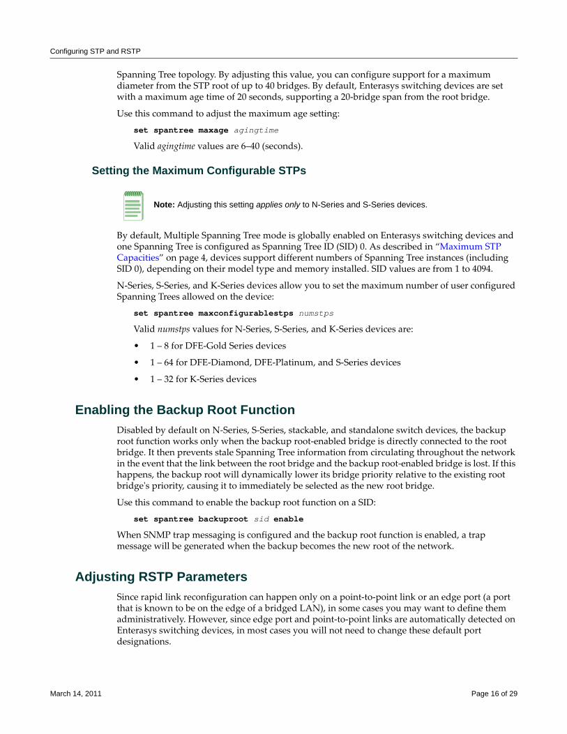
Configuring STP and RSTP
Spanning Tree topology. By adjusting this value, you can configure support for a maximum diameter from the STP root of up to 40 bridges. By default, Enterasys switching devices are set with a maximum age time of 20 seconds, supporting a 20‐bridge span from the root bridge.
Use this command to adjust the maximum age setting:
set spantree maxage agingtime
Valid agingtime values are 6–40 (seconds).
Setting the Maximum Configurable STPs
By default, Multiple Spanning Tree mode is globally enabled on Enterasys switching devices and one Spanning Tree is configured as Spanning Tree ID (SID) 0. As described in “Maximum STP Capacities” on page 4, devices support different numbers of Spanning Tree instances (including SID 0), depending on their model type and memory installed. SID values are from 1 to 4094.
N‐Series, S‐Series, and K‐Series devices allow you to set the maximum number of user configured Spanning Trees allowed on the device:
set spantree maxconfigurablestps numstps
Valid numstps values for N‐Series, S‐Series, and K‐Series devices are:
• 1 – 8 for DFE‐Gold Series devices
• 1 – 64 for DFE‐Diamond, DFE‐Platinum, and S‐Series devices
• 1 – 32 for K‐Series devices
Enabling the Backup Root FunctionDisabled by default on N‐Series, S‐Series, stackable, and standalone switch devices, the backup root function works only when the backup root‐enabled bridge is directly connected to the root bridge. It then prevents stale Spanning Tree information from circulating throughout the network in the event that the link between the root bridge and the backup root‐enabled bridge is lost. If this happens, the backup root will dynamically lower its bridge priority relative to the existing root bridgeʹs priority, causing it to immediately be selected as the new root bridge.
Use this command to enable the backup root function on a SID:
set spantree backuproot sid enable
When SNMP trap messaging is configured and the backup root function is enabled, a trap message will be generated when the backup becomes the new root of the network.
Adjusting RSTP ParametersSince rapid link reconfiguration can happen only on a point‐to‐point link or an edge port (a port that is known to be on the edge of a bridged LAN), in some cases you may want to define them administratively. However, since edge port and point‐to‐point links are automatically detected on Enterasys switching devices, in most cases you will not need to change these default port designations.
Note: Adjusting this setting applies only to N-Series and S-Series devices.
March 14, 2011 Page 16 of 29
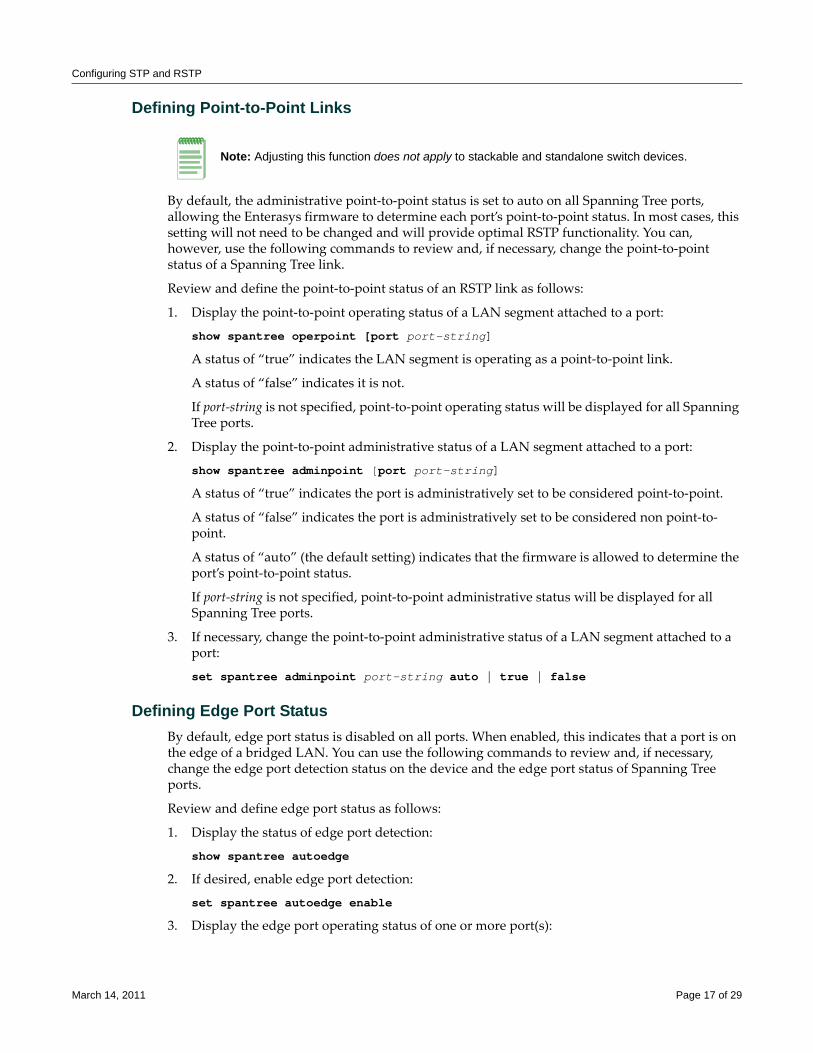
Configuring STP and RSTP
Defining Point-to-Point Links
By default, the administrative point‐to‐point status is set to auto on all Spanning Tree ports, allowing the Enterasys firmware to determine each port’s point‐to‐point status. In most cases, this setting will not need to be changed and will provide optimal RSTP functionality. You can, however, use the following commands to review and, if necessary, change the point‐to‐point status of a Spanning Tree link.
Review and define the point‐to‐point status of an RSTP link as follows:
1. Display the point‐to‐point operating status of a LAN segment attached to a port:
show spantree operpoint [port port-string]
A status of “true” indicates the LAN segment is operating as a point‐to‐point link.
A status of “false” indicates it is not.
If port‐string is not specified, point‐to‐point operating status will be displayed for all Spanning Tree ports.
2. Display the point‐to‐point administrative status of a LAN segment attached to a port:
show spantree adminpoint [port port-string]
A status of “true” indicates the port is administratively set to be considered point‐to‐point.
A status of “false” indicates the port is administratively set to be considered non point‐to‐point.
A status of “auto” (the default setting) indicates that the firmware is allowed to determine the port’s point‐to‐point status.
If port‐string is not specified, point‐to‐point administrative status will be displayed for all Spanning Tree ports.
3. If necessary, change the point‐to‐point administrative status of a LAN segment attached to a port:
set spantree adminpoint port-string auto | true | false
Defining Edge Port StatusBy default, edge port status is disabled on all ports. When enabled, this indicates that a port is on the edge of a bridged LAN. You can use the following commands to review and, if necessary, change the edge port detection status on the device and the edge port status of Spanning Tree ports.
Review and define edge port status as follows:
1. Display the status of edge port detection:
show spantree autoedge
2. If desired, enable edge port detection:
set spantree autoedge enable
3. Display the edge port operating status of one or more port(s):
Note: Adjusting this function does not apply to stackable and standalone switch devices.
March 14, 2011 Page 17 of 29
Configuring MSTP
show spantree operedge [port port-string]
A status of “true” or “Edge‐Port” indicates the port is operating as an edge port.
A status of “false” or “Non‐Edge‐Port” indicates it is not.
If port‐string is not specified, edge port status will be displayed for all Spanning Tree ports.
4. Display the edge port administrative status of one or more port(s):
show spantree adminedge [port port-string]
A status of “true” or “Edge‐Port” indicates the port is administratively set to be considered an edge port.
A status of “false” or “Non‐Edge‐Port” indicates the port is administratively set to be considered a non edge port.
If port‐string is not specified, edge port administrative status will be displayed for all Spanning Tree ports.
5. If necessary, change the edge port administrative status of one or more port(s):
set spantree adminedge port-string true
Configuring MSTPIn order for MSTP to provide multiple forwarding paths, the following must happen:
• The configuration identifier must match on all bridges within the region.
• All bridges must be within the same region.
• All bridges must be connected to MSTP‐aware bridges. (They can be connected using a shared media such as a repeater provided that a single Spanning Tree device does not reside on that LAN).
This section provides information about the following MSTP tasks:
• Example: Simple MSTP Configuration (page 18)
• Adjusting MSTP Parameters (page 19)
• Monitoring MSTP (page 19)
Example: Simple MSTP ConfigurationThe following example describes setting up the simple MSTP network shown in Figure 7. By default, each switching device will be in its own MST region using its own MAC address as the MST configuration ID. This configuration groups Switch 1 and Switch 2 into a single MST region with an MSTI configuration name of “South.” It maps VLAN 2 to MSTI SID 2 and VLAN 3 to MSTI SID 3.
Note: A single Spanning Tree device between two MSTP bridges will terminate the ability to have multiple forwarding paths.
March 14, 2011 Page 18 of 29
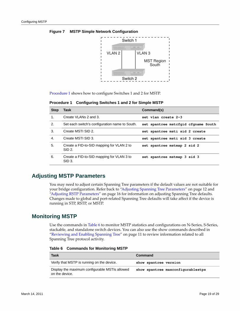
Configuring MSTP
Figure 7 MSTP Simple Network Configuration
Procedure 1 shows how to configure Switches 1 and 2 for MSTP.
Adjusting MSTP ParametersYou may need to adjust certain Spanning Tree parameters if the default values are not suitable for your bridge configuration. Refer back to “Adjusting Spanning Tree Parameters” on page 12 and “Adjusting RSTP Parameters” on page 16 for information on adjusting Spanning Tree defaults. Changes made to global and port‐related Spanning Tree defaults will take affect if the device is running in STP, RSTP, or MSTP.
Monitoring MSTPUse the commands in Table 6 to monitor MSTP statistics and configurations on N‐Series, S‐Series, stackable, and standalone switch devices. You can also use the show commands described in “Reviewing and Enabling Spanning Tree” on page 11 to review information related to all Spanning Tree protocol activity.
Procedure 1 Configuring Switches 1 and 2 for Simple MSTP
Step Task Command(s)
1. Create VLANs 2 and 3. set vlan create 2-3
2. Set each switch’s configuration name to South. set spantree mstcfgid cfgname South
3. Create MSTI SID 2. set spantree msti sid 2 create
4. Create MSTI SID 3. set spantree msti sid 3 create
5. Create a FID-to-SID mapping for VLAN 2 to SID 2.
set spantree mstmap 2 sid 2
6. Create a FID-to-SID mapping for VLAN 3 to SID 3.
set spantree mstmap 3 sid 3
Table 6 Commands for Monitoring MSTPTask Command
Verify that MSTP is running on the device. show spantree version
Display the maximum configurable MSTIs allowed on the device.
show spantree maxconfigurablestps
March 14, 2011 Page 19 of 29
Understanding and Configuring SpanGuard
Understanding and Configuring SpanGuardThis section provides information about the following SpanGuard topics and tasks:
• What Is SpanGuard? (page 20)
• How Does It Operate? (page 20)
• Configuring SpanGuard (page 21)
What Is SpanGuard?As described previously in the overview of SpanGuard on page 5, this feature enables Enterasys switching devices to detect unauthorized bridges in your network, resolving the threat of repeated topology change notifications or new root bridge announcements causing a Denial of Service (DoS) condition. It prevents Spanning Tree respans that can occur when BPDUs are received on user ports and notifies you (network management) they were attempted.
If a SpanGuard enabled port receives a BPDU, it becomes locked and transitions to the blocking state. It will only transition out of the blocking state after a globally specified time or when it is manually unlocked.
By default, SpanGuard is globally disabled on N‐Series, S‐Series, stackable, and standalone switch devices and must be globally enabled to operate on all user ports. For configuration information, refer to “Configuring SpanGuard” on page 21.
How Does It Operate?SpanGuard helps protect against Spanning Tree Denial of Service (DoS) SpanGuard attacks as well as unintentional/unauthorized connected bridges by intercepting received BPDUs on configured ports and locking these ports so they do not process any received packets.
When enabled, reception of a BPDU on a port that is administratively configured as a Spanning Tree edge port (adminedge = True) will cause the port to become locked and the state set to blocking. When this condition is met, packets received on that port will not be processed for a specified timeout period. The port will become unlocked when either:
Display a list of MSTIs configured on the device. show spantree mstilist
Display the mapping of one or more filtering database IDs (FIDs) to Spanning Trees. Since VLANs are mapped to FIDs, this shows to which SID a VLAN is mapped.
show spantree mstmap [fid fid]
Display the Spanning Tree ID(s) assigned to one or more VLANs.
show spantree vlanlist [vlan-list]
Display MST configuration identifier elements, including format selector, configuration name, revision level, and configuration digest.
show spantree mstcfgid
Display protocol-specific MSTP counter information. show spantree debug [port port-string] [sid sid] [active]
Table 6 Commands for Monitoring MSTP (continued)Task Command
March 14, 2011 Page 20 of 29
Understanding and Configuring SpanGuard
• the timeout expires,
• the port is manually unlocked,
• the port is no longer administratively configured as adminedge = True, or
• the SpanGuard function is disabled.
The port will become locked again if it receives another offending BPDU after the timeout expires or it is manually unlocked.
In the event of a DoS attack with SpanGuard enabled and configured, no Spanning Tree topology changes or topology reconfigurations will be seen in your network. The state of your Spanning Tree will be completely unaffected by the reception of any spoofed BPDUs, regardless of the BPDU type, rate received or duration of the attack.
By default, when SNMP and SpanGuard are enabled, a trap message will be generated when SpanGuard detects that an unauthorized port has tried to join a Spanning Tree.
Configuring SpanGuardUse the following commands to configure device ports for SpanGuard, to enable the SpanGuard function, and to review SpanGuard status on the device.
Reviewing and Setting Edge Port Status
Review and set edge port status as follows:
1. Use the show commands described in “Defining Edge Port Status” on page 17 to determine edge port administrative status on the device.
2. Set edge port administrative status to false on all known ISLs.
3. Set edge port administrative status to true on any remaining ports where SpanGuard protection is desired. This indicates to SpanGuard that these ports are not expecting to receive any BPDUs. If these ports do receive BPDUs, they will become locked.
Enabling and Adjusting SpanGuardUse this command to enable SpanGuard on the device:
set spantree spanguard enable
Use this command to adjust the SpanGuard timeout value. This sets the length of time that a SpanGuard‐affected port will remain locked:
set spantree spanguardtimeout timeout
Valid values are 0–65535 seconds. Default is 300 seconds. Setting the value to 0 will set the timeout to forever.
Use this command to manually unlock a port that was locked by the SpanGuard function. This overrides the specified timeout variable:
set spantree spanguardlock port-string
Note: In order to utilize the SpanGuard function, you must know which ports are connected between switching devices as ISLs (inter-switch links). Also, you must configure edge port status (adminedge = true or false) on the entire switch, as described in “Defining Edge Port Status” on page 17, before SpanGuard will work properly.
March 14, 2011 Page 21 of 29
Understanding and Configuring Loop Protect
Monitoring SpanGuard Status and SettingsUse the commands in Table 7 to review SpanGuard status and settings.
Understanding and Configuring Loop ProtectThis section provides information about the following Loop Protect topics and tasks:
• What Is Loop Protect? (page 22)
• How Does It Operate? (page 22)
• Configuring Loop Protect (page 25)
What Is Loop Protect?As described previously in the overview of Loop Protect on page 5, this feature prevents or short circuits loop formation in your network. It does this by requiring ports to receive type 2 BPDUs (RSTP/MSTP) on point‐to‐point inter‐switch links (ISLs) before their states are allowed to become forwarding. Further, if a BPDU timeout occurs on a port, its state becomes non‐forwarding until a BPDU is received.
In this way, both upstream and downstream facing ports are protected. When a root or alternate port loses its path to the root bridge due to a message age expiration, it takes on the role of designated port and will not forward traffic until a BPDU is received.
When a port is intended to be the designated port in an ISL, it constantly proposes and will not forward until a BPDU is received. This protects against misconfiguration and protocol failure by the connected bridge.
How Does It Operate?Loop Protect operates as a per port, per MST instance feature and should be set on ISLs. It is comprised of several related functions, including:
• Controlling port forwarding state based on reception of agreement BPDUs
• Controlling port forwarding state based on reception of disputed BPDUs
• Communicating port non‐forwarding status through traps and syslog messages
• Disabling a port based on frequency of failure events
Table 7 Commands for Monitoring SpanGuardTask Command
Display the status of SpanGuard on the device. show spantree spanguard
Display the status of the SpanGuard lock function on one or more ports.
show spantree spanguardlock [port port-string]
Display the SpanGuard timeout setting. show spantree spanguardtimeout
Display the status of the SpanGuard trap function. show spantree spanguardtrapenable
March 14, 2011 Page 22 of 29
Understanding and Configuring Loop Protect
Port Modes and Event TriggersPorts work in two Loop Protect operational modes. If the port is configured so that it is connected to a switching device known to implement Loop Protect, it uses full functional (enhanced) mode. Otherwise, it operates in limited functional (standard) mode.
Connection to a Loop Protect switching device guarantees that the alternate agreement mechanism is implemented and, therefore, the designated port can rely on receiving a response to its proposal regardless of the role of the connected port. This has two important implications. First, the designated port connected to a non‐root port may transition to forwarding. Second, there is no ambiguity when a timeout happens; a Loop Protect event has occurred.
In full mode, when a type 2 BPDU is received and the port is designated and point‐to‐point, the timer is set to 3 times helloTime. Limited mode adds a further requirement that the flags field in the BPDU indicates a root role. If the port is a boundary port, the MSTIs for that port follow the CIST (for example if the MSTI port timers are set according to the CIST port timer). If the port is internal to the region, then the MSTI port timers are set independently using the particular MSTI message.
Loop Protect initializes the MSTI timer to zero and does not allow the designated port to transition from listening to learning until the timer becomes non‐zero. If the port is not designated, the timer does not apply. Its state is controlled through normal protocol behavior.
A disputed BPDU is one in which the flags field indicates a designated role, a learning state, and the priority vector is worse than that already held by the port. If a disputed BPDU is received, the port is forced to the listening state.
Message age expiration and the expiration of the Loop Protect timer are both events for which Loop Protect generates a notice level syslog message. You can also configure traps to report these events, as well as a syslog message and trap for disputed BPDUs.
In addition, you can configure Loop Protect to force the locking of a SID/port when one or more events occurs. When the configured number of events happen within a given window of time, the port will be forced into blocking and held there until you manually unlock it.
Example: Basic Loop Protect ConfigurationThe following sample configuration shows how Loop Protect functions in a basic Spanning Tree topology.
In the example in Figure 8, Switch 1 is the root bridge with BPDUs being sent to both Switch 2 and 3. (Designated ports are labeled D and root ports are labeled R.) Switch 3 has placed the port that connects to Switch 2 in a blocking state.
March 14, 2011 Page 23 of 29
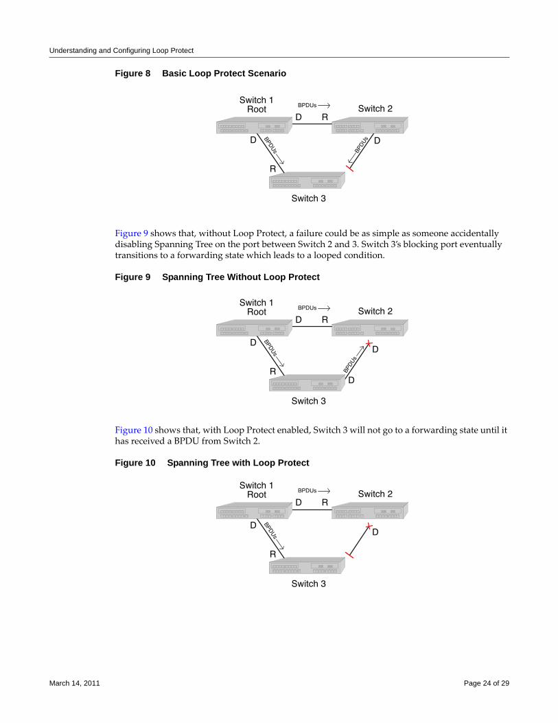
Understanding and Configuring Loop Protect
Figure 8 Basic Loop Protect Scenario
Figure 9 shows that, without Loop Protect, a failure could be as simple as someone accidentally disabling Spanning Tree on the port between Switch 2 and 3. Switch 3’s blocking port eventually transitions to a forwarding state which leads to a looped condition.
Figure 9 Spanning Tree Without Loop Protect
Figure 10 shows that, with Loop Protect enabled, Switch 3 will not go to a forwarding state until it has received a BPDU from Switch 2.
Figure 10 Spanning Tree with Loop Protect
March 14, 2011 Page 24 of 29
Understanding and Configuring Loop Protect
Configuring Loop ProtectThis section provides information about Loop Protect configuration:
• Enabling or Disabling Loop Protect (page 25)
• Specifying Loop Protect Partners (page 25)
• Setting the Loop Protect Event Threshold and Window (page 25)
• Enabling or Disabling Loop Protect Event Notifications (page 26)
• Setting the Disputed BPDU Threshold (page 26)
• Monitoring Loop Protect Status and Settings (page 26)
Enabling or Disabling Loop ProtectBy default, Loop Protect is disabled on all ports. Use this command to enable (or, if desired, disable) the feature on one or more ports:
set spantree lp port-string {enable | disable} [sid sid]
If no SID is specified, SID 0 is assumed.
This command takes precedence over per port STP enable/disable state (portAdmin). Normally, portAdmin disabled would cause a port to go immediately to forwarding. If Loop Protect is enabled, that port should go to listening and remain there.
Specifying Loop Protect PartnersBy default, each port is not set as a Loop Protect capable partner. If the port is set as a Loop Protect capable partner (true), then the full functionality of the Loop Protect feature is used. If the value is false, then there is some ambiguity as to whether an Active Partner timeout is due to a loop protection event or is a normal situation due to the fact that the partner port does not transmit Alternate Agreement BPDUs. Therefore, a conservative approach is taken in that designated ports will not be allowed to forward unless receiving agreements from a port with root role. This type of timeout will not be considered a loop protection event. Loop protection is maintained by keeping the port from forwarding, but since this is not considered a loop event, it will not be factored into locking the port.
Use this command to set the Loop Protect partner state on one or more ports:
set spantree lpcapablepartner port-string {true | false}
Setting the Loop Protect Event Threshold and WindowThe Loop Protect event threshold is a global integer variable that provides protection in the case of intermittent failures. The default value is 3. If the event counter reaches the threshold within a given period (the event window), then the port for the given SID becomes locked (that is, held indefinitely in the blocking state). If the threshold is 0, the ports are never locked.
Use this command to set the Loop Protect event threshold:
set spantree lpthreshold value
Note: The Loop Protect enable/disable settings for an MSTI port should match those for the CIST port.
March 14, 2011 Page 25 of 29
Understanding and Configuring Loop Protect
The Loop Protect window is a timer value, in seconds, that defines a period during which Loop Protect events are counted. The default value is 180 seconds. If the timer is set to 0, the event counter is not reset until the Loop Protect event threshold is reached.
Use this command to set the Loop Protect event window value in seconds:
set spantree lpwindow value
Enabling or Disabling Loop Protect Event NotificationsLoop Protect traps are sent when a Loop Protect event occurs, that is, when a port goes to listening due to not receiving BPDUs. The trap indicates port, SID and loop protection status.
Use this command to enable or disable Loop Protect event notification. By default, this is disabled:
set spantree lptrapenable {enable | disable}
Setting the Disputed BPDU ThresholdA disputed BPDU is one in which the flags field indicates a designated role and a learning state, and the priority vector is worse than that already held by the port. If a disputed BPDU is received, the port is forced to the listening state. Refer to the 802.1Q‐2005 standard, IEEE Standard for Local and Metropolitan Area Networks – Virtual Bridged Local Area Networks, for a full description of the dispute mechanism, which prevents looping in cases of one‐way communication.
The disputed BPDU threshold is an integer variable that represents the number of disputed BPDUs that must be received on a given port/SID until a disputed BPDU trap is sent and a syslog message is issued. For example, if the threshold is 10, then a trap is issued when 10, 20, 30 (and so on) disputed BPDUs have been received. The trap indicates port, SID and total Disputed BPDU count.
Use this command to set the disputed BPDU threshold:
set spantree disputedbpduthreshold value
Default value is 0, which means that traps are not sent.
Monitoring Loop Protect Status and SettingsUse the commands in Table 8 to monitor Loop Protect settings.
Table 8 Commands for Monitoring Loop ProtectTask Command
Display the Loop Protect status per port, per SID, or both.
show spantree lp [port port-string] [sid sid]
Display the Loop Protect lock status per port, per SID, or both.
Note: A port can become locked if a configured number of Loop Protect events occur during the configured window of time. Once a port is forced into blocking (locked), it remains locked until manually unlocked with the clear spantree lplock command.
show spantree lplock [port port-string] [sid sid]
Display the Loop Protect capability of a link partner for one or more ports.
show spantree lpcapablepartner [port port-string]
March 14, 2011 Page 26 of 29
Terms and Definitions
ExampleThe following example shows a switching device with Loop Protect enabled on port lag.0.2, SID 56:
Enterasys->show spantree lp port lag.0.2 sid 56
LoopProtect is enabled on port lag.0.2, SID 56
Enterasys->show spantree lplock port lag.0.2 sid 56
LoopProtect Lock status for port lag.0.2, SID 56_ is UNLOCKED
Enterasys->show spantree lpcapablepartner port lag.0.2
Link partner of port lag.0.2_is LoopProtect-capable.
Enterasys->show spantree nonforwardingreason port lag.0.2
Port lag.0.2 has been placed in listening or blocking state on SID 0 by the LoopProtect feature.
Terms and DefinitionsTable 9 lists terms and definitions used in Spanning Tree configuration.
Display the reason for placing a port in a non-forwarding state due to an exceptional condition.
show spantree nonforwardingreason [port port-string] [sid sid]
Table 8 Commands for Monitoring Loop Protect (continued)Task Command
Table 9 Spanning Tree Terms and Definitions Term Definition
Alternate port Acts as an MSTP alternate path to the root bridge than that provided by the root port.
Backup port Acts as an MSTP backup for the path provided by a designated port toward the leaves of the Spanning Tree. Backup ports can exist only where two ports are connected together in a loopback mode or bridge with two or more connections to a shared LAN segment.
BID Bridge identification, which is derived from the bridge’s MAC address and bridge priority. The bridge with the lowest BID becomes the root bridge.
BPDU Bridge Protocol Data Unit messages. Used by STP to exchange information, including designating a bridge for each switched LAN segment, and one root bridge for the Spanning Tree.
Bridge Switching device.
Bridge priority Assigns the bridge’s relative priority compared to other bridges.
CIST Common and Internal Spanning Tree created by MSTP to represent the connectivity of the entire network. This is equivalent to the single Spanning Tree used for STP and RSTP. Communications between MST regions occurs using the CIST.
Designated port A forwarding port within an active topology elected for every switched LAN segment.
Edge port Port on the edge of a bridged LAN.
March 14, 2011 Page 27 of 29
Terms and Definitions
FID Filter Identifier. Each VLAN is associated to a FID. VLANs are mapped to SIDs using their FID association.
Forward delay Time interval (in seconds) the bridge spends in listening or learning mode before it begins forwarding BPDUs.
Hello time Time interval (in seconds) at which the bridge sends BPDUs.
ISLs Inter-Switch Links.
Loop Protect Prevents or short circuits loop formation in a network with redundant paths by requiring ports to receive type 2 BPDUs (RSTP/MSTP) on point-to-point inter-switch links (ISLs) before their states are allowed to become forwarding.
Master port The MSTI port whose connecting CIST port is root port for an entire MST region.
Max age Maximum time (in seconds) the bridge can wait without receiving a configuration message (bridge “hello”) before attempting to reconfigure.
MST region An MSTP group of devices configured together to form a logical region. The MST region presents itself to the rest of the network as a single device, which simplifies administration.
MSTI Multiple Spanning Tree Instance. N-Series, S-Series, stackable, and standalone switch devices support up to 64 MSTIs.
Path cost Sum of the port costs in the best path to the root bridge.
Port cost Value assigned to a port based on the speed of the port. The faster the speed, the lower the cost. This helps to determine the quickest path between the root bridge and a specified destination. The segment attached to the root bridge normally has a path cost of zero.
Port priority Assigns a port’s priority in relation to the other ports on the same bridge.
Root bridge Logical center of the Spanning Tree, used by STP to determine which paths to block and which to open.
Root port Port in an active topology through which the root bridge can be reached.
SID Spanning tree identifier. By default, SID 0 is assumed. VLANs are mapped to SIDs using their FID association.
SpanGuard Prevents Spanning Tree respans that can occur when BPDUs are received on user ports and notifies network management that they were attempted.
Table 9 Spanning Tree Terms and Definitions (continued)Term Definition
March 14, 2011 Page 28 of 29
Enterasys Networks reserves the right to make changes in specifications and other information contained in this document and its web site without prior notice. The reader should in all cases consult Enterasys Networks to determine whether any such changes have been made.
The hardware, firmware, or software described in this document is subject to change without notice.
IN NO EVENT SHALL ENTERASYS NETWORKS BE LIABLE FOR ANY INCIDENTAL, INDIRECT, SPECIAL, OR CONSEQUENTIAL DAMAGES WHATSOEVER (INCLUDING BUT NOT LIMITED TO LOST PROFITS) ARISING OUT OF OR RELATED TO THIS DOCUMENT, WEB SITE, OR THE INFORMATION CONTAINED IN THEM, EVEN IF ENTERASYS NETWORKS HAS BEEN ADVISED OF, KNEW OF, OR SHOULD HAVE KNOWN OF, THE POSSIBILITY OF SUCH DAMAGES.
Enterasys Networks, Inc.50 Minuteman RoadAndover, MA 01810
© 2011 Enterasys Networks, Inc. All rights reserved.
ENTERASYS, ENTERASYS NETWORKS, ENTERASYS NETSIGHT, and any logos associated therewith, are trademarks or registered trademarks of Enterasys Networks, Inc., in the United States and other countries. For a complete list of Enterasys trademarks, see http://www.enterasys.com/company/trademarks.aspx.
All other product names mentioned in this manual may be trademarks or registered trademarks of their respective companies.
Revision History
Date Description
01-16-2008 New document.
02-20-2008 Corrected product naming conventions.
07-28-2008 Modifications due to product branding changes.
01-20-2009 Corrected description of Spanning Tree instance capacities.
03-14-2011 Updated to include S-Series and K-Series devices.
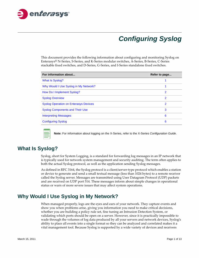
Configuring Syslog
This document provides the following information about configuring and monitoring Syslog on Enterasys® N‐Series, S‐Series, and K‐Series modular switches, A‐Series, B‐Series, C‐Series stackable fixed switches, and D‐Series, G‐Series, and I‐Series standalone fixed switches.
What Is Syslog?Syslog, short for System Logging, is a standard for forwarding log messages in an IP network that is typically used for network system management and security auditing. The term often applies to both the actual Syslog protocol, as well as the application sending Syslog messages.
As defined in RFC 3164, the Syslog protocol is a client/server‐type protocol which enables a station or device to generate and send a small textual message (less than 1024 bytes) to a remote receiver called the Syslog server. Messages are transmitted using User Datagram Protocol (UDP) packets and are received on UDP port 514. These messages inform about simple changes in operational status or warn of more severe issues that may affect system operations.
Why Would I Use Syslog in My Network?When managed properly, logs are the eyes and ears of your network. They capture events and show you when problems arise, giving you information you need to make critical decisions, whether you are building a policy rule set, fine tuning an Intrusion Detection System, or validating which ports should be open on a server. However, since it is practically impossible to wade through the volumes of log data produced by all your servers and network devices, Syslog’s ability to place all events into a single format so they can be analyzed and correlated makes it a vital management tool. Because Syslog is supported by a wide variety of devices and receivers
For information about... Refer to page...
What Is Syslog? 1
Why Would I Use Syslog in My Network? 1
How Do I Implement Syslog? 2
Syslog Overview 2
Syslog Operation on Enterasys Devices 2
Syslog Components and Their Use 3
Interpreting Messages 6
Configuring Syslog 6
Note: For information about logging on the X-Series, refer to the X-Series Configuration Guide.
March 15, 2011 Page 1 of 13
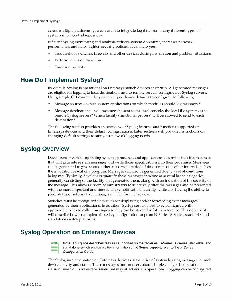
How Do I Implement Syslog?
across multiple platforms, you can use it to integrate log data from many different types of systems into a central repository.
Efficient Syslog monitoring and analysis reduces system downtime, increases network performance, and helps tighten security policies. It can help you:
• Troubleshoot switches, firewalls and other devices during installation and problem situations.
• Perform intrusion detection.
• Track user activity.
How Do I Implement Syslog?By default, Syslog is operational on Enterasys switch devices at startup. All generated messages are eligible for logging to local destinations and to remote servers configured as Syslog servers. Using simple CLI commands, you can adjust device defaults to configure the following:
• Message sources—which system applications on which modules should log messages?
• Message destinations—will messages be sent to the local console, the local file system, or to remote Syslog servers? Which facility (functional process) will be allowed to send to each destination?
The following section provides an overview of Syslog features and functions supported on Enterasys devices and their default configurations. Later sections will provide instructions on changing default settings to suit your network logging needs.
Syslog OverviewDevelopers of various operating systems, processes, and applications determine the circumstances that will generate system messages and write those specifications into their programs. Messages can be generated to give status, either at a certain period of time, or at some other interval, such as the invocation or exit of a program. Messages can also be generated due to a set of conditions being met. Typically, developers quantify these messages into one of several broad categories, generally consisting of the facility that generated them, along with an indication of the severity of the message. This allows system administrators to selectively filter the messages and be presented with the more important and time sensitive notifications quickly, while also having the ability to place status or informative messages in a file for later review.
Switches must be configured with rules for displaying and/or forwarding event messages generated by their applications. In addition, Syslog servers need to be configured with appropriate rules to collect messages so they can be stored for future reference. This document will describe how to complete these key configuration steps on N‐Series, S‐Series, stackable, and standalone switch platforms.
Syslog Operation on Enterasys Devices
The Syslog implementation on Enterasys devices uses a series of system logging messages to track device activity and status. These messages inform users about simple changes in operational status or warn of more severe issues that may affect system operations. Logging can be configured
Note: This guide describes features supported on the N-Series, S-Series, K-Series, stackable, and standalone switch platforms. For information on X-Series support, refer to the X-Series Configuration Guide.
March 15, 2011 Page 2 of 13
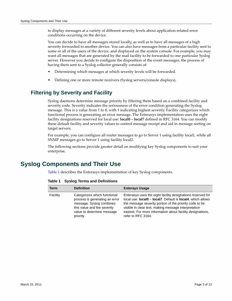
Syslog Components and Their Use
to display messages at a variety of different severity levels about application‐related error conditions occurring on the device.
You can decide to have all messages stored locally, as well as to have all messages of a high severity forwarded to another device. You can also have messages from a particular facility sent to some or all of the users of the device, and displayed on the system console. For example, you may want all messages that are generated by the mail facility to be forwarded to one particular Syslog server. However you decide to configure the disposition of the event messages, the process of having them sent to a Syslog collector generally consists of:
• Determining which messages at which severity levels will be forwarded.
• Defining one or more remote receivers (Syslog servers/console displays).
Filtering by Severity and FacilitySyslog daemons determine message priority by filtering them based on a combined facility and severity code. Severity indicates the seriousness of the error condition generating the Syslog message. This is a value from 1 to 8, with 1 indicating highest severity. Facility categorizes which functional process is generating an error message. The Enterasys implementation uses the eight facility designations reserved for local use: local0 – local7 defined in RFC 3164. You can modify these default facility and severity values to control message receipt and aid in message sorting on target servers.
For example, you can configure all router messages to go to Server 1 using facility local1, while all SNMP messages go to Server 1 using facility local2.
The following sections provide greater detail on modifying key Syslog components to suit your enterprise.
Syslog Components and Their UseTable 1 describes the Enterasys implementation of key Syslog components.
Table 1 Syslog Terms and Definitions
Term Definition Enterays Usage
Facility Categorizes which functional process is generating an error message. Syslog combines this value and the severity value to determine message priority.
Enterasys uses the eight facility designations reserved for local use: local0 – local7. Default is local4, which allows the message severity portion of the priority code to be visible in clear text, making message interpretation easiest. For more information about facility designations, refer to RFC 3164.
March 15, 2011 Page 3 of 13

Syslog Components and Their Use
Basic Syslog ScenarioFigure 1 shows a basic scenario of how Syslog components operate on an Enterasys switch. By default, all applications running on the Enterasys switch are allowed to forward Syslog messages generated at severity levels 6 through 1. In the configuration shown, these default settings have not been changed.
Severity Indicates the severity of the error condition generating the Syslog message. The lower the number value, the higher will be the severity of the condition generating the message.
Enterasys devices provide the following eight levels:
1 - emergencies (system is unusable)2 - alerts (immediate action required)3 - critical conditions4 - error conditions5 - warning conditions6 - notifications (significant conditions)7 - informational messages8 - debugging messages
The default Syslog configuration allows applications (log message sources) to forward messages at a severity level of 6, and destinations (console, file system, or remote Syslog servers) to log messages at a severity level of 8.
Note: Numerical values used in Enterasys syslog CLI and the feature's configuration MIB range from 1-8. These map to the RFC 3164 levels of 0-7 respectively. Syslog messages generated report the RFC 3164 specified level values.
Application Client software applications running on devices that can generate Syslog messages.
Enterasys supported applications and their associated CLI mnemonic values include:
CLI - Command Line InterfaceSNMP - Simple Network Management ProtocolWebview - Enterasys Web-based system managementSystem - System messagesRtrFe - Router Forwarding EngineTrace - Trace loggingRtrLSNat - Load Share Network Address TranslationFlowLimt - Flow limitingUPN - User Personalized NetworksAAA - Authentication, Authorization and Accounting
Use the show logging application all command to list supported applications and the corresponding CLI numeric or mnemonic values you can use to configure application logging on your devices.
Syslog server A remote server configured to collect and store Syslog messages.
Enterasys devices allow up to 8 server IP addresses to be configured as destinations for Syslog messages. By default, Syslog server is globally enabled, with no IP addresses configured, at a severity level of 8.
Table 1 Syslog Terms and Definitions (continued)
Term Definition Enterays Usage
March 15, 2011 Page 4 of 13
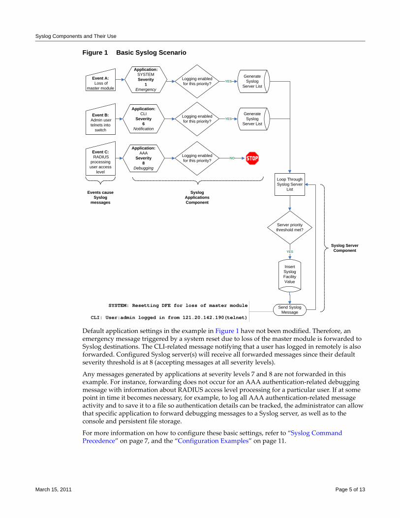
Syslog Components and Their Use
Figure 1 Basic Syslog Scenario
Default application settings in the example in Figure 1 have not been modified. Therefore, an emergency message triggered by a system reset due to loss of the master module is forwarded to Syslog destinations. The CLI‐related message notifying that a user has logged in remotely is also forwarded. Configured Syslog server(s) will receive all forwarded messages since their default severity threshold is at 8 (accepting messages at all severity levels).
Any messages generated by applications at severity levels 7 and 8 are not forwarded in this example. For instance, forwarding does not occur for an AAA authentication‐related debugging message with information about RADIUS access level processing for a particular user. If at some point in time it becomes necessary, for example, to log all AAA authentication‐related message activity and to save it to a file so authentication details can be tracked, the administrator can allow that specific application to forward debugging messages to a Syslog server, as well as to the console and persistent file storage.
For more information on how to configure these basic settings, refer to “Syslog Command Precedence” on page 7, and the “Configuration Examples” on page 11.
Event A: Loss of
master module
Event B: Admin user telnets into
switch
Event C: RADIUS
processing user access
level
Application:CLI
Severity6
Notification
Application:SYSTEMSeverity
1 Emergency
Application:AAA
Severity8
Debugging
Logging enabled for this priority?
Generate Syslog
Server List
Generate Syslog
Server List
YES
YES
NO
Events cause Syslog
messages
Logging enabled for this priority?
Logging enabled for this priority?
Syslog Applications Component
Loop Through Syslog Server
List
Server priority threshold met?
Insert Syslog Facility Value
YES
Send Syslog Message
Syslog Server Component
SYSTEM: Resetting DFE for loss of master module
CLI: User:admin logged in from 121.20.142.190(telnet)
March 15, 2011 Page 5 of 13
Interpreting Messages
Interpreting MessagesEvery system message generated by the Enterasys switch platforms follows the same basic format:
<facility/severity> time stamp address application [slot] message text
ExampleThis example shows Syslog informational messages, displayed with the show logging buffer command. It indicates that messages were generated by facility code 16 (local4) at severity level 5 from the CLI application on IP address 10.42.71.13.
Switch1(rw)->show logging buffer<165>Sep 4 07:43:09 10.42.71.13 CLI[5]User:rw logged in from 10.2.1.122 (telnet)<165>Sep 4 07:43:24 10.42.71.13 CLI[5]User: debug failed login from 10.4.1.100(telnet)
Table 2 describes the components of these messages.
Configuring SyslogUse the procedures in this section to perform the following logging configuration tasks:
• Syslog Command Precedence (page 7)
• Configuring Syslog Server(s) (page 7)
• Modifying Syslog Server Defaults (page 8)
• Reviewing and Configuring Logging for Applications (page 9)
• Enabling Console Logging and File Storage (page 10)
• Configuration Examples (page 11)
Table 2 Syslog Message Components
Component Description Example Code
Facility/Severity Combined code indicating the facility generating the message and the severity level used to determine message priority. Facility codes 16 - 23 are Syslog designations for local0 - local7, the Enterasys supported designations for local use. For a complete list of facility codes, refer to RFC 3164.
<165> = Numerical code indicating a message from facility local4 at severity 5.
Time stamp Month, date, and time the Syslog message appeared.
Sep 4 07:43:09
Address IP address of the client originating the Syslog message.
10.42.71.13
Application Client process generating the Syslog message. CLI
Slot/Module Slot location of the device module generating the Syslog message.
(5) = Slot 5 in the chassis.
Message text Brief description of error condition. User: debug failed login from 10.4.1.100 (telnet)
March 15, 2011 Page 6 of 13
Configuring Syslog
Syslog Command PrecedenceTable 3 lists basic Syslog commands and their order of precedence on Enterays switches.
About Server and Application Severity LevelsBy default, client applications will forward Syslog messages at severity levels 6 through 1, and servers will log messages at all severity levels (8 through 1). You can use the procedures described in this chapter to change these parameters, fine tuning the scope of message logging and modifying the Syslog behavior between one or more client applications and one or more servers.
Configuring Syslog Server(s)Use the following commands to configure one or more servers as destinations for Syslog messages and verify the configuration:
1. Add a Syslog server to the device’s server list:
set logging server index ip-addr ip-addr state enable
Index is a value from 1 to 8 that specifies the server table index number for this server.
2. (Optional) Verify the server configuration:
show logging server [index]
If index is not specified, information for all configured Syslog servers will be displayed.
Table 3 Syslog Command Precedence
Syslog Component Command Function
Logging defaults set logging default {[facility facility] [severity severity] [port port]}
Sets default parameters for facility code, severity level and/or UDP port for all Syslog servers and local destinations.
Settings will be applied when Syslog servers are configured without specifying values with the set logging server command. This command overrides factory defaults.
Server settings set logging server index ip-addr ip-addr [facility facility] [severity severity] [descr descr] [port port] state enable | disable
During or after new server setup, specifies a server index, IP address, and operational state for a Syslog server. Optionally, this command specifies a facility code, severity level at which messages will be accepted, text string description, and/or UDP port for the specified server.
This command overrides system defaults for the specified server. If not specified with this or the set logging default command, optional server parameters will be set to the system defaults listed in Table 4 on page 8.
Application settings set logging application {[mnemonic|all]} [level level] [servers servers]
Sets the severity level at which one or all applications will send messages to Syslog servers. If not specified, settings will apply to all configured servers and severity level will not be changed from system defaults.
March 15, 2011 Page 7 of 13
Configuring Syslog
ExampleThis sample output from the show logging server command shows that two servers have been added to the device’s Syslog server list. These servers are using the default UDP port 514 to receive messages from clients and are configured to log messages from the local1 and local2 facilities, respectively. Logging severity on both servers is set at 5 (accepting messages at severity levels 5 through 1). Using the commands described in the next section, these settings can be changed on a per‐server basis, or for all servers.
Switch1(rw)->show logging server
IP Address Facility Severity Description Port Status ------------------------------------------------------------------------- 1 132.140.82.111 local1 warning(5) default 514 enabled 2 132.140.90.84 local2 warning(5) default 514 enabled
Modifying Syslog Server DefaultsUnless otherwise specified, the switch will use the default server settings listed in Table 4 for its configured Syslog servers:
Use the following commands to change these settings either during or after enabling a new server.
Displaying System Logging DefaultsTo display system logging defaults, or all logging information, including defaults:
show logging {default|all}
Modifying Default SettingsYou can change factory default logging settings using one of the following methods.
• To specify logging parameters during or after new server setup:
set logging server index ip-addr ip-addr [facility facility] [severity severity] [descr descr] [port port] state enable
If not specified, optional server parameters will be set to the system defaults listed in Table 4. Refer back to Filtering by Severity and Facility and to Table 1 for more information on how these parameters operate.
• To change default parameters for all servers:
set logging default {[facility facility] [severity severity] [port port]}
Table 4 Syslog Server Default SettingsParameter Default Setting
facility local4
severity 8 (accepting all levels)
descr no description applied
port UDP port 514
March 15, 2011 Page 8 of 13
Configuring Syslog
ExamplesThis example shows how to configure the switch to forward messages from facility category local6 at severity levels 3, 2, and 1 to Syslog server 1 at IP address 134.141.89.113:
Switch1(rw)->set logging server 1 ip-addr 134.141.89.113 facility local6 severity 3
This example shows how to change Syslog defaults so that messages from the local2 facility category at a severity level of 4 will be forwarded to all servers. These settings will apply to all newly‐configured servers, unless explicitly configured with the set logging server command:
Switch1(rw)->set logging default facility local2 severity 4
Reviewing and Configuring Logging for ApplicationsBy default, all applications running on Enterasys switch devices are allowed to forward messages at severity levels 6 through 1 to all configured destinations (Syslog servers, the console, or the file system).
Displaying Current Application Severity LevelsTo display logging severity levels for one or all applications currently running on your device:
show logging application {mnemonic|all}
ExampleThis example shows output from the show logging application all command. A numeric and mnemonic value for each application is listed with the severity level at which logging has been configured and the server(s) to which messages will be sent. In this case, logging for applications has not been changed from the default severity level of 6. This means that notifications and messages with severity values 6 through 1 will be sent to configured servers.
Switch1(rw)->show logging application allApplication Current Severity Level Server List---------------------------------------------------------- 88 RtrAcl 6 1-8 89 CLI 6 1-8 90 SNMP 6 1-8 91 Webview 6 1-8 93 System 6 1-8 95 RtrFe 6 1-8 96 Trace 6 1-8 105 RtrLSNat 6 1-8 111 FlowLimt 6 1-8 112 UPN 6 1-8 117 AAA 6 1-8 118 Router 6 1-8 140 AddrNtfy 6 1-8 141 OSPF 6 1-8 142 VRRP 6 1-8 145 RtrArpProc 6 1-8 147 LACP 6 1-8 148 RtrNat 6 1-8 151 RtrTwcb 6 1-8 158 HostDoS 6 1-8
1(emergencies) 2(alerts) 3(critical)
March 15, 2011 Page 9 of 13
Configuring Syslog
4(errors) 5(warnings) 6(notifications)7(information) 8(debugging)
Modifying Severity Levels and Assigning Syslog Servers for ApplicationsApplications running on Enterasys devices will use the default Syslog settings unless otherwise configured by the set logging server or set logging default commands as previously described.
To modify the severity level at which log messages will be forwarded and the server(s) to which they will be sent for one or all applications:
set logging application {[mnemonic|all]} [level level] [servers servers]
ExampleThis example shows how to set the severity level for SSH (Secure Shell) to 5 so that warning conditions and messages of greater severity (levels 5 to 1) generated by that application will be sent to Syslog server 1.
Switch1(rw)->set logging application SSH level 5 server 1
Enabling Console Logging and File StorageStackable and standalone switch devices allow you to display logging messages to the console and save to a persistent file. In addition, N‐Series, S‐Series, and K‐Series devices also provide the option of allowing you to display messages to the current console CLI session only (set logging here).
Console logging allows you to view only as many messages as will fit on the screen. As new messages appear, old messages simply scroll off the console. While this is a temporary means of logging information, it allows you to track very specific activities quickly and easily. Console log messages can also be saved to a persistent file. On the N‐Series, S‐Series, and K‐Series, console log messages can be saved to a persistent file at two locations:
• slotX/logs/current.log — Location of current system log messages (up to 256k), where X specifies the slot location of the device.
• slotX/logs/old.log — Location of previous system log messages, where X specifies the slot location of the device. Current messages will be moved to the old.log when current.log file exceeds 256k.
Use the following commands to review and configure console logging and file storage.
Displaying to the Console and Saving to a FileTo display log messages to the console and save to a persistent file:
set logging local console enable file enable
Note: Mnemonic values are case sensitive and must be typed as they are listed in the show logging application command display for your device. Refer to Table 1 for sample CLI mnemonic values.
Depending on your platform, you may see different applications listed from those shown in the example above.
Note: The set logging local command requires that you specify both console and file settings. For example, set logging local console enable would not execute without also specifying file enable or disable.
March 15, 2011 Page 10 of 13
Configuring Syslog
Displaying to the Current CLI Session
To display logging to the current CLI console session on an N‐Series, S‐Series, or K‐Series device:
set logging here enable
This adds the current CLI session to the list of Syslog destinations, and will be temporary if the current CLI session is using Telnet or SSH.
Displaying a Log FileTo display the contents of the persistent log file on N‐Series, S‐Series, and K‐Series devices:
show file slotslotnumber/logs/current.log|old.log
Configuration Examples
Enabling a Server and Console LoggingProcedure 1 shows how you would complete a basic Syslog configuration. In this example, the default application severity level has not been modified, allowing all applications to forward messages to configured destinations. One Syslog server is configured on IP address 10.1.1.2, logging all messages. Console logging is enabled, but persistent file storage is not.
Adjusting Settings to Allow for Logging at the Debug LevelProcedure 2 shows how you would adjust the previous Syslog configuration so that all AAA‐related authentication messages (level 8) could be forwarded to Server 2 at IP address 10.1.1.3, displayed on the console and saved to persistent file storage. This would enable all Syslog messaging capabilities for this particular application. Since the severity for this new server has not changed from the default of level 8, there is no need to adjust this setting.
Note: This function is not supported on stackable or standalone fixed switches.
Notes: These log files may also be copied to another device using FTP or TFTP.
You cannot display the contents of the persistent log file on stackable or standalone switches. Use the show logging buffer command to show the most recent entries.
Procedure 1 Configuring a Server and Console Logging
Step Task Command(s)
1. Configure Syslog server 1 and accept default settings (listed in Table 4 on page 8).
set logging server 1 ip-addr 10.1.1.2 state enable
2. (Optional) Verify that application logging settings are at default values for the enabled server.
show logging application all
3. Enable console logging and disable file storage. set logging local console enable file disable
Note: The set logging local command requires that you specify both console and file settings. For example, set logging local console enable would not execute without also specifying file enable or disable.
March 15, 2011 Page 11 of 13
Configuring Syslog
Procedure 2 Adjusting Settings for an Application
Step Task Command(s)
1. Configure Syslog server 2 and accept default settings (listed in Table 4 on page 8).
set logging server 2 ip-addr 10.1.1.3 state enable
2. Set the severity level for the AAA application to level 8.
set logging application AAA level 8 servers 2
3. Enable console logging and file storage. set logging local console enable file enable
March 15, 2011 Page 12 of 13
Enterasys Networks reserves the right to make changes in specifications and other information contained in this document and its web site without prior notice. The reader should in all cases consult Enterasys Networks to determine whether any such changes have been made.
The hardware, firmware, or software described in this document is subject to change without notice.
IN NO EVENT SHALL ENTERASYS NETWORKS BE LIABLE FOR ANY INCIDENTAL, INDIRECT, SPECIAL, OR CONSEQUENTIAL DAMAGES WHATSOEVER (INCLUDING BUT NOT LIMITED TO LOST PROFITS) ARISING OUT OF OR RELATED TO THIS DOCUMENT, WEB SITE, OR THE INFORMATION CONTAINED IN THEM, EVEN IF ENTERASYS NETWORKS HAS BEEN ADVISED OF, KNEW OF, OR SHOULD HAVE KNOWN OF, THE POSSIBILITY OF SUCH DAMAGES.
Enterasys Networks, Inc.50 Minuteman RoadAndover, MA 01810
© 2011 Enterasys Networks, Inc. All rights reserved.
ENTERASYS, ENTERASYS NETWORKS, ENTERASYS NETSIGHT, and any logos associated therewith, are trademarks or registered trademarks of Enterasys Networks, Inc., in the United States and other countries. For a complete list of Enterasys trademarks, see http://www.enterasys.com/company/trademarks.aspx.
All other product names mentioned in this manual may be trademarks or registered trademarks of their respective companies.
Revision History
Date Description
04-04-2008 New document
07-28-2008 Modifications due to product rebranding changes.
11-14-2008 Text corrections.
03-15-2011 Added S-Series and K-Series.
Configuring TACACS+
This document provides information about configuring and monitoring TACACS+ (Terminal Access Controller Access‐Control System Plus) on Enterasys devices.
What is TACACS+?TACACS+, a security protocol developed by Cisco Systems, can be used as an alternative to the standard RADIUS security protocol (RFC 2865). TACACS+ runs over TCP and encrypts the body of each packet.
Based on the now obsolete TACACS protocol (defined in RFC 1492), TACACS+ is defined in an un‐published and expired Internet Draft draft‐grant‐tacacs‐02.txt, “The TACACS+ Protocol Version 1.78,” January, 1997.
Why Would I Use TACACS+ in My Network?TACACS+ provides the following services:
• User authentication
• User authorization
• Accounting (user activity)
Notes: TACACS+ is supported on most Enterasys devices, with the exception of some Enterasys fixed switches. Refer to your Enterasys device’s Release Notes to determine if your device supports TACACS+.
For information on Enterasys Matrix® X-Series TACACS+ support, refer to the Enterasys Matrix X Secure Core Router Configuration Guide.
For information about... Refer to page...
What is TACACS+? 1
Why Would I Use TACACS+ in My Network? 1
How Do I Implement TACACS+? 2
Understanding TACACS+ 2
Configuring TACACS+ 3
December 2, 2010 Page 1 of 7
How Do I Implement TACACS+?
How Do I Implement TACACS+?You can configure the TACACS+ client on your Enterasys device in conjunction with one or more (up to eight) TACACS+ access servers to provide authentication, authorization, or accounting services on your network. Each of the TACACS+ services can be implemented on separate servers.
You can also configure TACACS+ to use a single TCP connection for all TACACS+ client requests to a given TACACS+ server.
For more information about the basic TACACS+ configuration, see “Basic TACACS+ Configuration” on page 4.
Understanding TACACS+TACACS+ client functionality falls into four basic capabilities:
• Authentication and session authorization
• Command authorization
• Session accounting
• Command accounting
Session Authorization and AccountingThe TACACS+ client is disabled by default. When the TACACS+ client is enabled on an Enterasys device and a session is initiated, the configured session authorization parameters are sent by the client to the TACACS+ server. The parameter values must match a service and access level attribute‐value pair configured on the server for the session to be authorized. If the parameter values do not match, the session is not allowed.
The service name and attribute‐value pairs can be any character string, and are determined by your TACACS+ server configuration.
When session accounting is enabled, the TACACS+ server logs accounting information, such as start and stop times, IP address of the remote user, and so forth, for each authorized client session.
Command Authorization and AccountingTACACS+ command authorization and accounting can occur only during a TACACS+ authorized session.
When command authorization is enabled, the TACACS+ server checks whether each command is permitted for that authorized session and returns a success or failure for each one. If the authorization fails, the command is not executed.
When command accounting is enabled, the TACACS+ server logs accounting information, such as the command string and IP address of the remote user for each command executed during the session.
December 2, 2010 Page 2 of 7
Configuring TACACS+
Configuring TACACS+
Default SettingsTable 1 lists the TACACS+ parameters (as displayed through the show tacacs command) and their default values.
Table 1 TACACS+ Parameters
Parameter Description Default Value
TACACS+ state Whether the TACACS+ client is enabled or disabled. Disabled
TACACS+ service The name of the service that is requested by the TACACS+ client for session authorization.
exec
TACACS+ session authorization A-V pairs
The attribute-value pairs that are mapped to the read-only, read-write, and super-user access privilege levels for the service requested for session authorization.
read-only: “priv-lvl”, 0
read-write: “priv-lvl”, 1
super-user: “priv-lvl”, 15
TACACS+ session accounting state
The TACACS+ client sends session accounting information, such as start and stop times, to a TACACS+ server for logging.
Disabled
TACACS+ command authorization state
The TACACS+ client checks with a TACACS+ server whether each command is permitted for that authorized session.
Disabled
TACACS+ command accounting state
The TACACS+ client sends command accounting information, such as the command string and IP address of the remote user, to a TACACS+ server for logging.
Disabled
TACACS+ singleconnect state
The TACACS+ client sends multiple requests to a TACACS+ server over a single TCP connection.
Disabled
TACACS+ Server Timeout
The period of time (in seconds) the device waits for a response from the TACACS+ server before it times out and declares an error.
10 seconds
December 2, 2010 Page 3 of 7
Configuring TACACS+
Basic TACACS+ ConfigurationProcedure 1 describes the basic steps to configure TACACS+ on Enterasys devices. It assumes that you have gathered the necessary TACACS+ server information, such as the server’s IP address, the TCP port to use, shared secret, the authorization service name, and access level attribute‐value pairs.
Note: You must be logged in to the Enterasys device with read-write access rights to use the commands shown in this procedure.
Procedure 1 TACACS+ Configuration
Step Task Command(s)
1. Enable the TACACS+ client.
To disable the TACACS+ client, use the set tacacs disable command.
set tacacs enable
2. Configure the TACACS+ servers, up to a maximum of eight, to be used by the TACACS+ client. Define the IP address, TCP port, and secret for each server. Optionally, change the timeout for each server from the default, 10 seconds. Possible timeout values are 1–30 seconds.
To remove one or all configured TACACS+ servers, or return the timeout value to its default value for one or all configured TACACS+ servers, use the clear tacacs server {all | index} [timeout] command.
set tacacs server {index [ipaddress port secret]] | all timeout seconds}
3. Optionally, enable session accounting.
To disable TACACS+ session accounting, use the set tacacs session accounting disable command.
set tacacs session accounting enable
4. Optionally, configure the TACACS+ session authorization service or access level. The default service name is “exec.” Refer to Table 1 on page 3 for the default values of the access level attribute-value pairs.
To return the TACACS+ session authorization settings to their default values, use the clear tacacs session authorization {[service] [read-only] [read-write] [superuser]} command.
set tacacs session {authorization service name | read-only attribute value | read-write attribute value | super-user attribute value}
5. Optionally, enable per-command accounting.
To disable TACACS+ accounting on a per-command basis, use the set tacacs command accounting disable command.
set tacacs command accounting enable
6. Optionally, enable per-command authorization.
To disable TACACS+ authorization on a per-command basis, use the set tacacs command authorization disable command.
set tacacs command authorization enable
December 2, 2010 Page 4 of 7
Configuring TACACS+
Refer to the device’s CLI Reference or Configuration Guide, as appropriate, for more information about each command.
Example TACACS+ ConfigurationIn the following configuration example on an S‐Series device, the TACACS+ server is defined as having the IP address 192.168.10.10. The TCP port is set to 49, which is the standard TACACS+ TCP port. The authorization service is set to “basic” and the read‐write access privilege is set to 5. Session and command accounting are enabled, as is command authorization. A single TCP connection will be used for all TACACS+ communication with 192.168.10.10. Finally, the primary login authentication method is set to TACACS+.
S Chassis(rw)->set tacacs enable
S Chassis(rw)->set tacacs server 1 192.168.10.10 49 mysecret
S Chassis(rw)->set tacacs session accounting enable
S Chassis(rw)->set tacacs session authorization service basic
S Chassis(rw)->set tacacs session authorization read-write priv-lvl 5
S Chassis(rw)->set tacacs command accounting enable
S Chassis(rw)->set tacacs command authorization enable
S Chassis(rw)->set tacacs singleconnect enable
S Chassis(rw)->set authentication login tacacs
7. Optionally, enable the TACACS+ client to send multiple requests to the server over a single TCP connection.
To disable the use of a single TCP connection, use the set tacacs singleconnect disable command.
set tacacs singleconnect enable
8. If not already configured, set the primary login authentication method to TACACS+.
set authentication login tacacs
Procedure 1 TACACS+ Configuration (continued)
Step Task Command(s)
December 2, 2010 Page 5 of 7
TACACS+ Display CommandsTable 2 lists TACACS+ show commands.
Refer to the device’s CLI Reference or Configuration Guide, as appropriate, for more information about each command.
Table 2 TACACS+ Show Commands
Task Command
Displays all current TACACS+ configuration information and status.
show tacacs [state]
Displays only the current configuration for one or all TACACS+ servers.
show tacacs server {index | all}
Displays only the current TACACS+ session settings. The [state] option is valid only for S-Series and Matrix N-Series devices.
show tacacs session {authorization | accounting} [state]
Displays only the current status for TACACS+ per-command authorization and accounting. The [state] option is valid only for S-Series and Matrix N-Series devices.
show tacacs command {accounting | authorization} [state]
Displays only the current singleconnect status. The [state] option is valid only for S-Series and Matrix N-Series devices.
show tacacs singleconnect [state]

Configuring TACACS+
Enterasys Networks reserves the right to make changes in specifications and other information contained in this document and its web site without prior notice. The reader should in all cases consult Enterasys Networks to determine whether any such changes have been made.
The hardware, firmware, or software described in this document is subject to change without notice.
IN NO EVENT SHALL ENTERASYS NETWORKS BE LIABLE FOR ANY INCIDENTAL, INDIRECT, SPECIAL, OR CONSEQUENTIAL DAMAGES WHATSOEVER (INCLUDING BUT NOT LIMITED TO LOST PROFITS) ARISING OUT OF OR RELATED TO THIS DOCUMENT, WEB SITE, OR THE INFORMATION CONTAINED IN THEM, EVEN IF ENTERASYS NETWORKS HAS BEEN ADVISED OF, KNEW OF, OR SHOULD HAVE KNOWN OF, THE POSSIBILITY OF SUCH DAMAGES.
Enterasys Networks, Inc.50 Minuteman RoadAndover, MA 01810
© 2010 Enterasys Networks, Inc. All rights reserved.
ENTERASYS, ENTERASYS NETWORKS, ENTERASYS MATRIX, ENTERASYS NETSIGHT, SECURESTACK, ENTERASYS SECURESTACK, LANVIEW, WEBVIEW, and any logos associated therewith, are trademarks or registered trademarks of Enterasys Networks, Inc., in the United States and other countries. For a complete list of Enterasys trademarks, see http://www.enterasys.com/company/trademarks.aspx.
All other product names mentioned in this manual may be trademarks or registered trademarks of their respective companies.
Revision History
Date Description
11-06-08 New document
12-02-10 Revised to include additional Enterasys devices
December 2, 2010 Page 7 of 7
Configuring Transparent Web Cache Balancing(TWCB)
This document provides the following information about configuring Transparent Web Cache Balancing on the Enterasys Matrix® N‐Series platform.
What is User Transparent Web Cache Balancing (TWCB)?Transparent Web Cache Balancing (TWCB) provides for the storing of frequently accessed web objects on a cache of local servers. Each HTTP request is transparently redirected by the N‐Series router to a configured cache server. When a user first accesses a web object, that object is stored on a cache server. Each subsequent request for the object uses this cached object, avoiding the need to access the host web site.
Why Would I Use TWCB in My Network?For most networks, web services are the primary consumer of network bandwidth. Web caching reduces network traffic and aides in optimizing bandwidth usage by localizing web traffic patterns, allowing content requests to be fulfilled locally. Web caching allows end‐users to access web objects stored on local cache‐servers with a much faster response time than accessing the same objects over an internet connection or through a default gateway. This can also result in substantial cost savings by reducing the internet bandwidth usage.
TWCB adds three important elements to standard web caching: transparency, load balancing, and scalability:
• In standard web caching, network users must set their browsers to cache web traffic. Because web caching is highly sensitive to user preference, users sometimes balk at this requirement, and the inability to control user behavior can be a problem for the network administrator. TWCB is said to be transparent to the user because web traffic is automatically rerouted, and the ability to configure caching is removed from the user and resides instead in the hands of the network administrator. With TWCB the user can not by‐pass web caching once set up by the network administrator. On the other hand, the network administrator can add users for
For information about... Refer to page...
What is User Transparent Web Cache Balancing (TWCB)? 1
Why Would I Use TWCB in My Network? 1
How Can I Implement TWCB? 2
TWCB Overview 2
Configuring TWCB 7
TWCB Configuration Example 10
April 16, 2009 Page 1 of 14
How Can I Implement TWCB?
whom web caching is not desired to a host redirection list, denying these users access to TWCB functionality.
• In standard web caching, a user‐cache is configured and assigned to a single cache server. TWCB provides for load balancing across all cache‐servers of a given server farm that can be configured for heavy web‐users using a predictor round‐robin algorithm.
• Scalability is provided by the ability to associate up to 128 cache‐servers with the web‐cache. This scalability is further refined by the ability to logically associate cache‐servers with up to 5 server farms.
How Can I Implement TWCB?Implementing TWCB requires a routed network with IP interfaces that allow the N‐Series router to send requests for the internet to the correct web caching device.
There are five aspects to TWCB configuration:
• Create the server farms that will cache the web objects and populate them with cache‐servers.
• Optionally associate heavy web‐users with a round‐robin list which caches those users’ web objects across all servers associated with the configured server farm.
• Optionally specify the hosts whose HTTP requests will or will not be redirected to the cache‐servers.
• Create a web‐cache that the server farms will be associated with.
• Apply the caching policy to an outbound interface, to redirect HTTP traffic on that interface to the cache‐servers.
TWCB Overview
A TWCB configuration is made up of one or more cache‐servers that are logically grouped in a server farm and one or more server farms that are associated with a web‐cache. The current TWCB implementation supports a single web‐cache.
Figure 1 on page 3 provides an overview of a TWCB configuration. In our overview, Cache1 is the name of the web‐cache. It is made up of two server farms: s1Server and s2Server. The s1Server server farm is configured with 2 cache‐servers from the 186.89.0.0 subnet. The s2Server server farm is configured with 5 cache‐servers from the 176.89.0.0 subnet. Web objects for each end‐user are cached on a cache server.
Notes: TWCB is currently only supported for N-Series products.
TWCB is an advanced routing feature that must be enabled with a license key. If you have purchased an advanced license key, and have enabled routing on the device, you must activate your license as described in the configuration guide that comes with your Enterasys Matrix DFE or NSA product in order to enable the TWCB command set. If you wish to purchase an advanced routing license, contact Enterasys Networks Sales.
A minimum of 256 MB of memory is required on all modules in order to enable TWCB. See the SDRAM field of the show system hardware command to display the amount of memory installed on a module. Module memory can be upgraded to 256 MB using the DFE-256MB-UGK memory kit.
April 16, 2009 Page 2 of 14
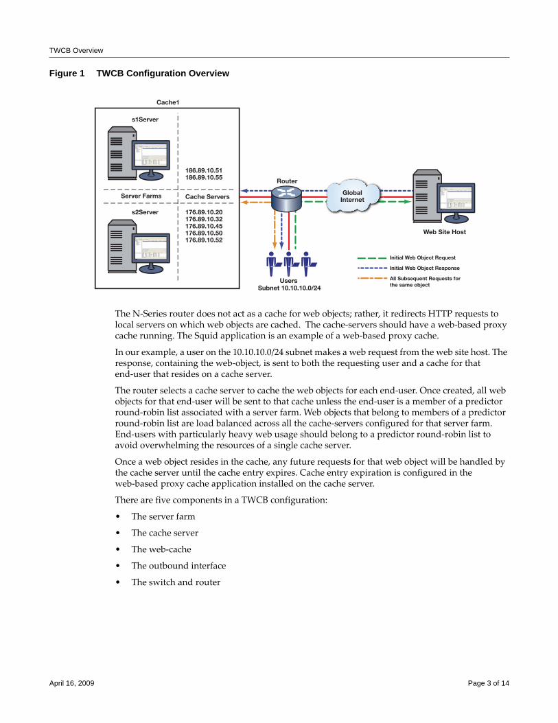
TWCB Overview
Figure 1 TWCB Configuration Overview
The N‐Series router does not act as a cache for web objects; rather, it redirects HTTP requests to local servers on which web objects are cached. The cache‐servers should have a web‐based proxy cache running. The Squid application is an example of a web‐based proxy cache.
In our example, a user on the 10.10.10.0/24 subnet makes a web request from the web site host. The response, containing the web‐object, is sent to both the requesting user and a cache for that end‐user that resides on a cache server.
The router selects a cache server to cache the web objects for each end‐user. Once created, all web objects for that end‐user will be sent to that cache unless the end‐user is a member of a predictor round‐robin list associated with a server farm. Web objects that belong to members of a predictor round‐robin list are load balanced across all the cache‐servers configured for that server farm. End‐users with particularly heavy web usage should belong to a predictor round‐robin list to avoid overwhelming the resources of a single cache server.
Once a web object resides in the cache, any future requests for that web object will be handled by the cache server until the cache entry expires. Cache entry expiration is configured in the web‐based proxy cache application installed on the cache server.
There are five components in a TWCB configuration:
• The server farm
• The cache server
• The web‐cache
• The outbound interface
• The switch and router
GlobalInternet
Users
Initial Web Object Request
Initial Web Object Response
All Subsequent Requests forthe same object
Router
Web Site Host
Cache1
186.89.10.51186.89.10.55
Subnet 10.10.10.0/24
176.89.10.20176.89.10.32176.89.10.45176.89.10.50176.89.10.52
Cache ServersServer Farms
s1Server
s2Server
April 16, 2009 Page 3 of 14
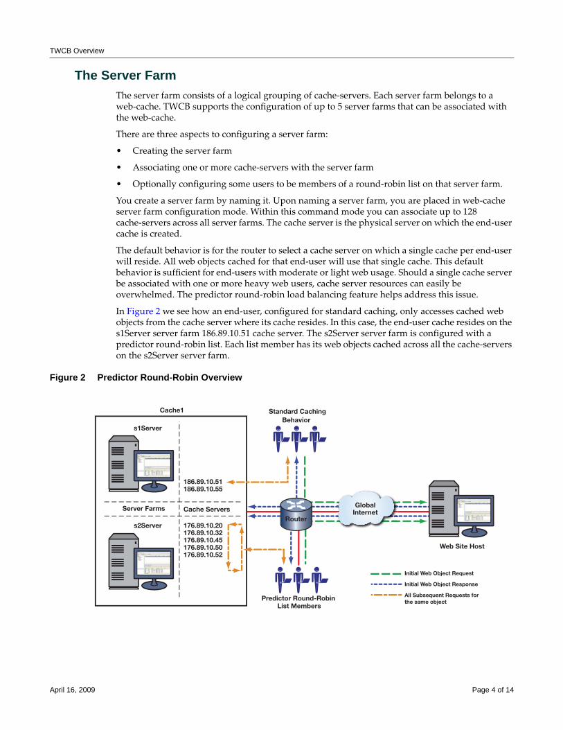
TWCB Overview
The Server FarmThe server farm consists of a logical grouping of cache‐servers. Each server farm belongs to a web‐cache. TWCB supports the configuration of up to 5 server farms that can be associated with the web‐cache.
There are three aspects to configuring a server farm:
• Creating the server farm
• Associating one or more cache‐servers with the server farm
• Optionally configuring some users to be members of a round‐robin list on that server farm.
You create a server farm by naming it. Upon naming a server farm, you are placed in web‐cache server farm configuration mode. Within this command mode you can associate up to 128 cache‐servers across all server farms. The cache server is the physical server on which the end‐user cache is created.
The default behavior is for the router to select a cache server on which a single cache per end‐user will reside. All web objects cached for that end‐user will use that single cache. This default behavior is sufficient for end‐users with moderate or light web usage. Should a single cache server be associated with one or more heavy web users, cache server resources can easily be overwhelmed. The predictor round‐robin load balancing feature helps address this issue.
In Figure 2 we see how an end‐user, configured for standard caching, only accesses cached web objects from the cache server where its cache resides. In this case, the end‐user cache resides on the s1Server server farm 186.89.10.51 cache server. The s2Server server farm is configured with a predictor round‐robin list. Each list member has its web objects cached across all the cache‐servers on the s2Server server farm.
Figure 2 Predictor Round-Robin Overview
GlobalInternet
Predictor Round-Robin
Initial Web Object Request
Initial Web Object Response
All Subsequent Requests forthe same object
Web Site Host
Cache1
186.89.10.51186.89.10.55
List Members
Standard CachingBehavior
176.89.10.20176.89.10.32176.89.10.45176.89.10.50176.89.10.52
Cache ServersServer Farms
s1Server
s2ServerRouter
April 16, 2009 Page 4 of 14
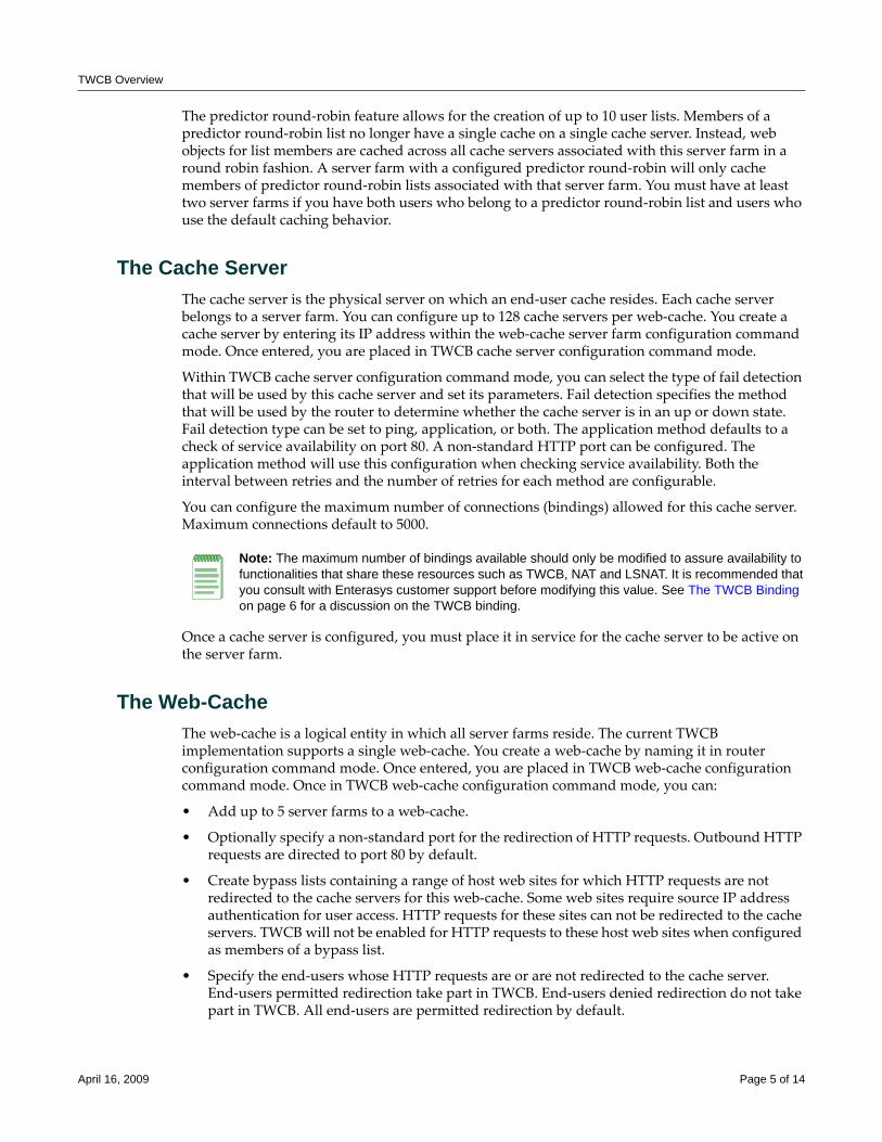
TWCB Overview
The predictor round‐robin feature allows for the creation of up to 10 user lists. Members of a predictor round‐robin list no longer have a single cache on a single cache server. Instead, web objects for list members are cached across all cache servers associated with this server farm in a round robin fashion. A server farm with a configured predictor round‐robin will only cache members of predictor round‐robin lists associated with that server farm. You must have at least two server farms if you have both users who belong to a predictor round‐robin list and users who use the default caching behavior.
The Cache ServerThe cache server is the physical server on which an end‐user cache resides. Each cache server belongs to a server farm. You can configure up to 128 cache servers per web‐cache. You create a cache server by entering its IP address within the web‐cache server farm configuration command mode. Once entered, you are placed in TWCB cache server configuration command mode.
Within TWCB cache server configuration command mode, you can select the type of fail detection that will be used by this cache server and set its parameters. Fail detection specifies the method that will be used by the router to determine whether the cache server is in an up or down state. Fail detection type can be set to ping, application, or both. The application method defaults to a check of service availability on port 80. A non‐standard HTTP port can be configured. The application method will use this configuration when checking service availability. Both the interval between retries and the number of retries for each method are configurable.
You can configure the maximum number of connections (bindings) allowed for this cache server. Maximum connections default to 5000.
Once a cache server is configured, you must place it in service for the cache server to be active on the server farm.
The Web-CacheThe web‐cache is a logical entity in which all server farms reside. The current TWCB implementation supports a single web‐cache. You create a web‐cache by naming it in router configuration command mode. Once entered, you are placed in TWCB web‐cache configuration command mode. Once in TWCB web‐cache configuration command mode, you can:
• Add up to 5 server farms to a web‐cache.
• Optionally specify a non‐standard port for the redirection of HTTP requests. Outbound HTTP requests are directed to port 80 by default.
• Create bypass lists containing a range of host web sites for which HTTP requests are not redirected to the cache servers for this web‐cache. Some web sites require source IP address authentication for user access. HTTP requests for these sites can not be redirected to the cache servers. TWCB will not be enabled for HTTP requests to these host web sites when configured as members of a bypass list.
• Specify the end‐users whose HTTP requests are or are not redirected to the cache server. End‐users permitted redirection take part in TWCB. End‐users denied redirection do not take part in TWCB. All end‐users are permitted redirection by default.
Note: The maximum number of bindings available should only be modified to assure availability to functionalities that share these resources such as TWCB, NAT and LSNAT. It is recommended that you consult with Enterasys customer support before modifying this value. See The TWCB Binding on page 6 for a discussion on the TWCB binding.
April 16, 2009 Page 5 of 14
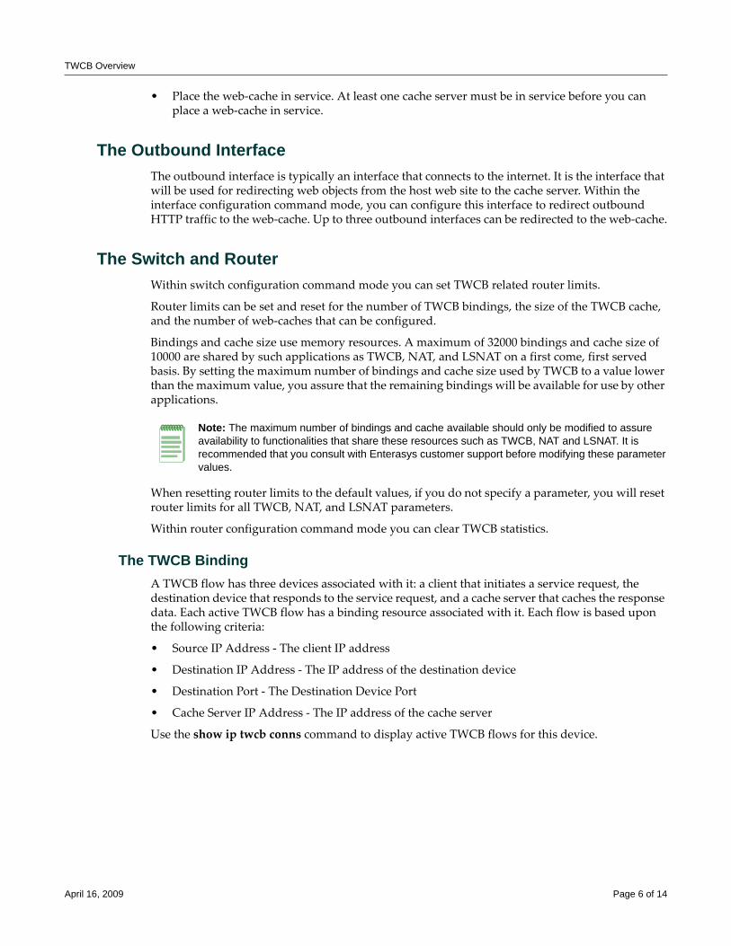
TWCB Overview
• Place the web‐cache in service. At least one cache server must be in service before you can place a web‐cache in service.
The Outbound InterfaceThe outbound interface is typically an interface that connects to the internet. It is the interface that will be used for redirecting web objects from the host web site to the cache server. Within the interface configuration command mode, you can configure this interface to redirect outbound HTTP traffic to the web‐cache. Up to three outbound interfaces can be redirected to the web‐cache.
The Switch and RouterWithin switch configuration command mode you can set TWCB related router limits.
Router limits can be set and reset for the number of TWCB bindings, the size of the TWCB cache, and the number of web‐caches that can be configured.
Bindings and cache size use memory resources. A maximum of 32000 bindings and cache size of 10000 are shared by such applications as TWCB, NAT, and LSNAT on a first come, first served basis. By setting the maximum number of bindings and cache size used by TWCB to a value lower than the maximum value, you assure that the remaining bindings will be available for use by other applications.
When resetting router limits to the default values, if you do not specify a parameter, you will reset router limits for all TWCB, NAT, and LSNAT parameters.
Within router configuration command mode you can clear TWCB statistics.
The TWCB BindingA TWCB flow has three devices associated with it: a client that initiates a service request, the destination device that responds to the service request, and a cache server that caches the response data. Each active TWCB flow has a binding resource associated with it. Each flow is based upon the following criteria:
• Source IP Address ‐ The client IP address
• Destination IP Address ‐ The IP address of the destination device
• Destination Port ‐ The Destination Device Port
• Cache Server IP Address ‐ The IP address of the cache server
Use the show ip twcb conns command to display active TWCB flows for this device.
Note: The maximum number of bindings and cache available should only be modified to assure availability to functionalities that share these resources such as TWCB, NAT and LSNAT. It is recommended that you consult with Enterasys customer support before modifying these parameter values.
April 16, 2009 Page 6 of 14
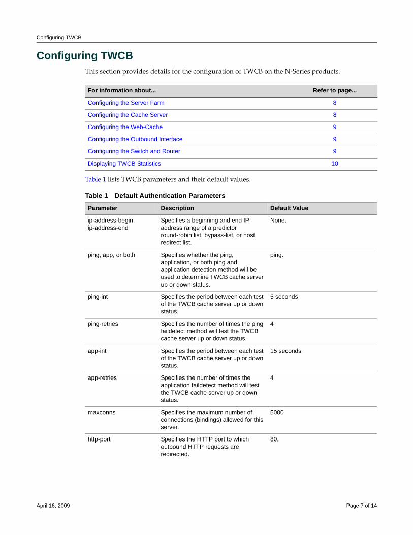
Configuring TWCB
Configuring TWCBThis section provides details for the configuration of TWCB on the N‐Series products.
Table 1 lists TWCB parameters and their default values.
For information about... Refer to page...
Configuring the Server Farm 8
Configuring the Cache Server 8
Configuring the Web-Cache 9
Configuring the Outbound Interface 9
Configuring the Switch and Router 9
Displaying TWCB Statistics 10
Table 1 Default Authentication Parameters
Parameter Description Default Value
ip-address-begin, ip-address-end
Specifies a beginning and end IP address range of a predictor round-robin list, bypass-list, or host redirect list.
None.
ping, app, or both Specifies whether the ping, application, or both ping and application detection method will be used to determine TWCB cache server up or down status.
ping.
ping-int Specifies the period between each test of the TWCB cache server up or down status.
5 seconds
ping-retries Specifies the number of times the ping faildetect method will test the TWCB cache server up or down status.
4
app-int Specifies the period between each test of the TWCB cache server up or down status.
15 seconds
app-retries Specifies the number of times the application faildetect method will test the TWCB cache server up or down status.
4
maxconns Specifies the maximum number of connections (bindings) allowed for this server.
5000
http-port Specifies the HTTP port to which outbound HTTP requests are redirected.
80.
April 16, 2009 Page 7 of 14
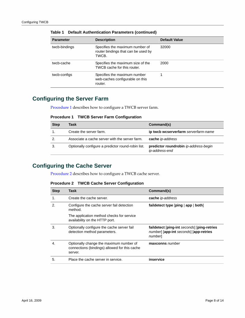
Configuring TWCB
Configuring the Server FarmProcedure 1 describes how to configure a TWCB server farm.
Configuring the Cache ServerProcedure 2 describes how to configure a TWCB cache server.
twcb-bindings Specifies the maximum number of router bindings that can be used by TWCB.
32000
twcb-cache Specifies the maximum size of the TWCB cache for this router.
2000
twcb-configs Specifies the maximum number web-caches configurable on this router.
1
Table 1 Default Authentication Parameters (continued)
Parameter Description Default Value
Procedure 1 TWCB Server Farm Configuration
Step Task Command(s)
1. Create the server farm. ip twcb wcserverfarm serverfarm-name
2. Associate a cache server with the server farm. cache ip-address
3. Optionally configure a predictor round-robin list. predictor roundrobin ip-address-begin ip-address-end
Procedure 2 TWCB Cache Server Configuration
Step Task Command(s)
1. Create the cache server. cache ip-address
2. Configure the cache server fail detection method.
The application method checks for service availability on the HTTP port.
faildetect type [ping | app | both]
3. Optionally configure the cache server fail detection method parameters.
faildetect [ping-int seconds] [ping-retries number] [app-int seconds] [app-retries number]
4. Optionally change the maximum number of connections (bindings) allowed for this cache server.
maxconns number
5. Place the cache server in service. inservice
April 16, 2009 Page 8 of 14
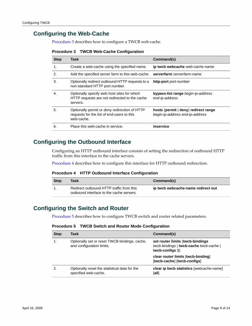
Configuring TWCB
Configuring the Web-CacheProcedure 3 describes how to configure a TWCB web‐cache.
Configuring the Outbound InterfaceConfiguring an HTTP outbound interface consists of setting the redirection of outbound HTTP traffic from this interface to the cache servers.
Procedure 4 describes how to configure this interface for HTTP outbound redirection.
Configuring the Switch and RouterProcedure 5 describes how to configure TWCB switch and router related parameters.
Procedure 3 TWCB Web-Cache Configuration
Step Task Command(s)
1. Create a web-cache using the specified name. ip twcb webcache web-cache-name
2. Add the specified server farm to this web-cache. serverfarm serverfarm-name
3. Optionally redirect outbound HTTP requests to a non-standard HTTP port number.
http-port port-number
4. Optionally specify web host sites for which HTTP requests are not redirected to the cache servers.
bypass-list range begin-ip-address end-ip-address
5. Optionally permit or deny redirection of HTTP requests for the list of end-users to this web-cache.
hosts {permit | deny} redirect range begin-ip-address end-ip-address
6. Place this web-cache in service. inservice
Procedure 4 HTTP Outbound Interface Configuration
Step Task Command(s)
1. Redirect outbound HTTP traffic from this outbound interface to the cache servers.
ip twcb webcache-name redirect out
Procedure 5 TWCB Switch and Router Mode Configuration
Step Task Command(s)
1. Optionally set or reset TWCB bindings, cache, and configuration limits.
set router limits {twcb-bindings twcb-bindings | twcb-cache twcb-cache | twcb-configs 1}
clear router limits [twcb-binding] [twcb-cache] [twcb-configs]
2. Optionally reset the statistical data for the specified web-cache.
clear ip twcb statistics [webcache-name] [all]
April 16, 2009 Page 9 of 14
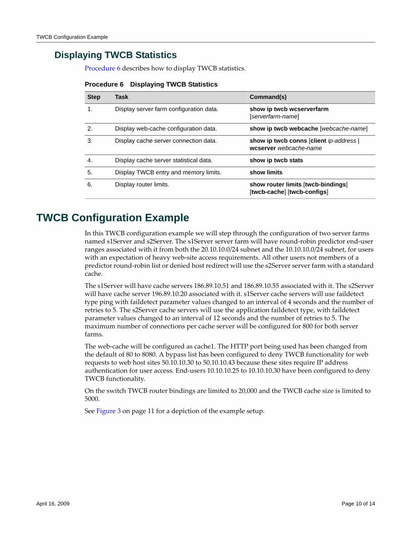
TWCB Configuration Example
Displaying TWCB StatisticsProcedure 6 describes how to display TWCB statistics.
TWCB Configuration ExampleIn this TWCB configuration example we will step through the configuration of two server farms named s1Server and s2Server. The s1Server server farm will have round‐robin predictor end‐user ranges associated with it from both the 20.10.10.0/24 subnet and the 10.10.10.0/24 subnet, for users with an expectation of heavy web‐site access requirements. All other users not members of a predictor round‐robin list or denied host redirect will use the s2Server server farm with a standard cache.
The s1Server will have cache servers 186.89.10.51 and 186.89.10.55 associated with it. The s2Server will have cache server 196.89.10.20 associated with it. s1Server cache servers will use faildetect type ping with faildetect parameter values changed to an interval of 4 seconds and the number of retries to 5. The s2Server cache servers will use the application faildetect type, with faildetect parameter values changed to an interval of 12 seconds and the number of retries to 5. The maximum number of connections per cache server will be configured for 800 for both server farms.
The web‐cache will be configured as cache1. The HTTP port being used has been changed from the default of 80 to 8080. A bypass list has been configured to deny TWCB functionality for web requests to web host sites 50.10.10.30 to 50.10.10.43 because these sites require IP address authentication for user access. End‐users 10.10.10.25 to 10.10.10.30 have been configured to deny TWCB functionality.
On the switch TWCB router bindings are limited to 20,000 and the TWCB cache size is limited to 5000.
See Figure 3 on page 11 for a depiction of the example setup.
Procedure 6 Displaying TWCB Statistics
Step Task Command(s)
1. Display server farm configuration data. show ip twcb wcserverfarm [serverfarm-name]
2. Display web-cache configuration data. show ip twcb webcache [webcache-name]
3. Display cache server connection data. show ip twcb conns [client ip-address | wcserver webcache-name
4. Display cache server statistical data. show ip twcb stats
5. Display TWCB entry and memory limits. show limits
6. Display router limits. show router limits [twcb-bindings] [twcb-cache] [twcb-configs]
April 16, 2009 Page 10 of 14
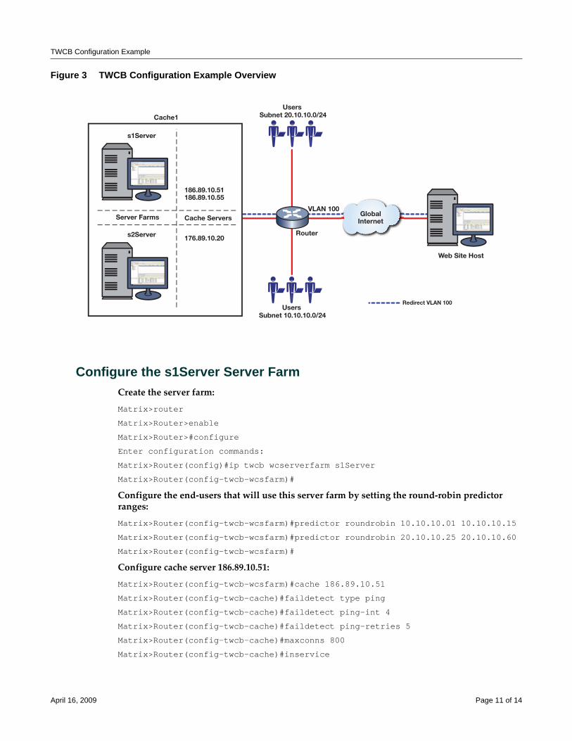
TWCB Configuration Example
Figure 3 TWCB Configuration Example Overview
Configure the s1Server Server FarmCreate the server farm:
Matrix>router
Matrix>Router>enable
Matrix>Router>#configure
Enter configuration commands:
Matrix>Router(config)#ip twcb wcserverfarm s1Server
Matrix>Router(config-twcb-wcsfarm)#
Configure the end‐users that will use this server farm by setting the round‐robin predictor ranges:
Matrix>Router(config-twcb-wcsfarm)#predictor roundrobin 10.10.10.01 10.10.10.15
Matrix>Router(config-twcb-wcsfarm)#predictor roundrobin 20.10.10.25 20.10.10.60
Matrix>Router(config-twcb-wcsfarm)#
Configure cache server 186.89.10.51:
Matrix>Router(config-twcb-wcsfarm)#cache 186.89.10.51
Matrix>Router(config-twcb-cache)#faildetect type ping
Matrix>Router(config-twcb-cache)#faildetect ping-int 4
Matrix>Router(config-twcb-cache)#faildetect ping-retries 5
Matrix>Router(config-twcb-cache)#maxconns 800
Matrix>Router(config-twcb-cache)#inservice
GlobalInternet
UsersRedirect VLAN 100
Router
VLAN 100
Web Site Host
Cache1
186.89.10.51186.89.10.55
Subnet 10.10.10.0/24
UsersSubnet 20.10.10.0/24
176.89.10.20
Cache ServersServer Farms
s1Server
s2Server
April 16, 2009 Page 11 of 14
TWCB Configuration Example
Matrix>Router(config-twcb-cache)#exit
Matrix>Router(config-twcb-wcsfarm)#
Configure cache server 186.89.10.55:
Matrix>Router(config-twcb-wcsfarm)#cache 186.89.10.55
Matrix>Router(config-twcb-cache)#faildetect type ping
Matrix>Router(config-twcb-cache)#faildetect ping-int 4
Matrix>Router(config-twcb-cache)#faildetect ping-retries 5
Matrix>Router(config-twcb-cache)#maxconns 800
Matrix>Router(config-twcb-cache)#inservice
Matrix>Router(config-twcb-cache)#exit
Matrix>Router(config-twcb-wcsfarm)#exit
Matrix>Router(config)#
Configure the s2Server Server FarmConfigure server farm s2Server:
Matrix>Router(config)#ip twcb wcserverfarm s2Server
Matrix>Router(config-twcb-wcsfarm)#
Configure cache server 176.89.10.20:
Matrix>Router(config-twcb-wcsfarm)#cache 176.89.10.20
Matrix>Router(config-twcb-cache)#faildetect type app
Matrix>Router(config-twcb-cache)#faildetect app-int 12
Matrix>Router(config-twcb-cache)#faildetect app-retries 5
Matrix>Router(config-twcb-cache)#maxconns 800
Matrix>Router(config-twcb-cache)#inservice
Matrix>Router(config-twcb-cache)#exit
Matrix>Router(config-twcb-wcsfarm)#exit
Matrix>Router(config)#
Configure the cache1 Web CacheConfigure the web‐cache cache1:
Matrix>Router(config)#ip twcb webcache cache1
Matrix>Router(config-twcb-webcache)#http-port 8080
Matrix>Router(config-twcb-webcache)#serverfarm s1Server
Matrix>Router(config-twcb-webcache)#serverfarm s2Server
Matrix>Router(config-twcb-webcache)#bypass-list range 50.10.10.30 50.10.10.43
Matrix>Router(config-twcb-webcache)#hosts redirect deny redirect range 10.10.10.25 10.10.10.30
Matrix>Router(config-twcb-webcache)#exit
Matrix>Router(config)#
April 16, 2009 Page 12 of 14
TWCB Configuration Example
Configure the outbound interface that connects with the internet:
Matrix>Router(config)#interface vlan 100
Matrix>Router(config-if(Vlan 1))#ip twcb cache1 redirect out
Matrix>Router(config-if(Vlan 1))#end
Matrix>Router#
Configure the Switch and RouterConfigure the TWCB router limits:
Matrix(rw)-> set router limits twcb-bindings 20000
Matrix(rw)-> set router limits twcb-cache 5000
Clear the statistical data for this web‐cache:
Matrix(rw)->Router#clear ip twcb statistics
This completes the TWCB configuration example.
April 16, 2009 Page 13 of 14
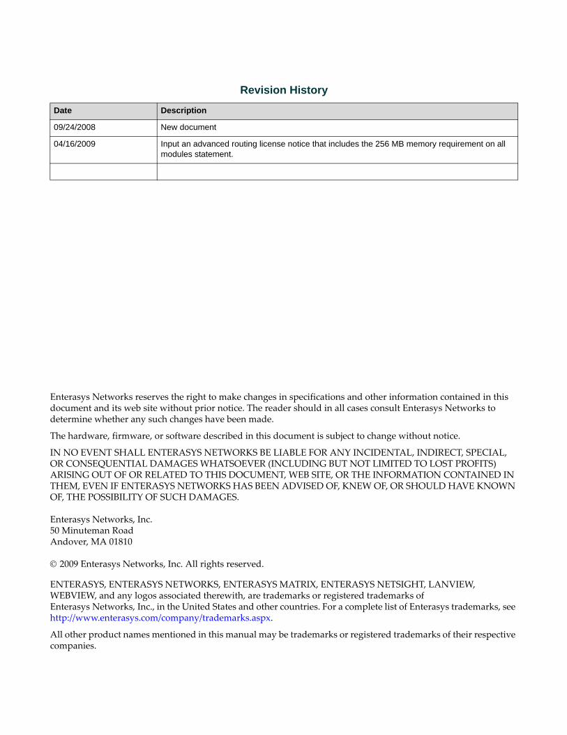
Enterasys Networks reserves the right to make changes in specifications and other information contained in this document and its web site without prior notice. The reader should in all cases consult Enterasys Networks to determine whether any such changes have been made.
The hardware, firmware, or software described in this document is subject to change without notice.
IN NO EVENT SHALL ENTERASYS NETWORKS BE LIABLE FOR ANY INCIDENTAL, INDIRECT, SPECIAL, OR CONSEQUENTIAL DAMAGES WHATSOEVER (INCLUDING BUT NOT LIMITED TO LOST PROFITS) ARISING OUT OF OR RELATED TO THIS DOCUMENT, WEB SITE, OR THE INFORMATION CONTAINED IN THEM, EVEN IF ENTERASYS NETWORKS HAS BEEN ADVISED OF, KNEW OF, OR SHOULD HAVE KNOWN OF, THE POSSIBILITY OF SUCH DAMAGES.
Enterasys Networks, Inc.50 Minuteman RoadAndover, MA 01810
© 2009 Enterasys Networks, Inc. All rights reserved.
ENTERASYS, ENTERASYS NETWORKS, ENTERASYS MATRIX, ENTERASYS NETSIGHT, LANVIEW, WEBVIEW, and any logos associated therewith, are trademarks or registered trademarks of Enterasys Networks, Inc., in the United States and other countries. For a complete list of Enterasys trademarks, see http://www.enterasys.com/company/trademarks.aspx.
All other product names mentioned in this manual may be trademarks or registered trademarks of their respective companies.
Revision History
Date Description
09/24/2008 New document
04/16/2009 Input an advanced routing license notice that includes the 256 MB memory requirement on all modules statement.
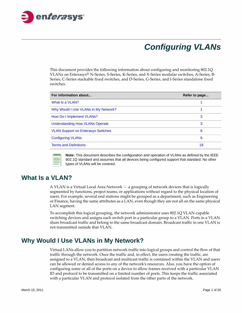
Configuring VLANs
This document provides the following information about configuring and monitoring 802.1Q VLANs on Enterasys® N‐Series, S‐Series, K‐Series, and X‐Series modular switches, A‐Series, B‐Series, C‐Series stackable fixed switches, and D‐Series, G‐Series, and I‐Series standalone fixed switches.
What Is a VLAN?A VLAN is a Virtual Local Area Network — a grouping of network devices that is logically segmented by functions, project teams, or applications without regard to the physical location of users. For example, several end stations might be grouped as a department, such as Engineering or Finance, having the same attributes as a LAN, even though they are not all on the same physical LAN segment.
To accomplish this logical grouping, the network administrator uses 802.1Q VLAN‐capable switching devices and assigns each switch port in a particular group to a VLAN. Ports in a VLAN share broadcast traffic and belong to the same broadcast domain. Broadcast traffic in one VLAN is not transmitted outside that VLAN.
Why Would I Use VLANs in My Network?Virtual LANs allow you to partition network traffic into logical groups and control the flow of that traffic through the network. Once the traffic and, in effect, the users creating the traffic, are assigned to a VLAN, then broadcast and multicast traffic is contained within the VLAN and users can be allowed or denied access to any of the network’s resources. Also, you have the option of configuring some or all of the ports on a device to allow frames received with a particular VLAN ID and protocol to be transmitted on a limited number of ports. This keeps the traffic associated with a particular VLAN and protocol isolated from the other parts of the network.
For information about... Refer to page...
What Is a VLAN? 1
Why Would I Use VLANs in My Network? 1
How Do I Implement VLANs? 3
Understanding How VLANs Operate 3
VLAN Support on Enterasys Switches 6
Configuring VLANs 9
Terms and Definitions 18
Note: This document describes the configuration and operation of VLANs as defined by the IEEE 802.1Q standard and assumes that all devices being configured support that standard. No other types of VLANs will be covered.
March 15, 2011 Page 1 of 20
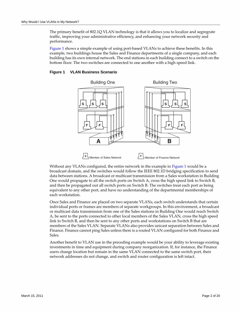
Why Would I Use VLANs in My Network?
The primary benefit of 802.1Q VLAN technology is that it allows you to localize and segregrate traffic, improving your administrative efficiency, and enhancing your network security and performance.
Figure 1 shows a simple example of using port‐based VLANs to achieve these benefits. In this example, two buildings house the Sales and Finance departments of a single company, and each building has its own internal network. The end stations in each building connect to a switch on the bottom floor. The two switches are connected to one another with a high speed link.
Figure 1 VLAN Business Scenario
Without any VLANs configured, the entire network in the example in Figure 1 would be a broadcast domain, and the switches would follow the IEEE 802.1D bridging specification to send data between stations. A broadcast or multicast transmission from a Sales workstation in Building One would propagate to all the switch ports on Switch A, cross the high speed link to Switch B, and then be propagated out all switch ports on Switch B. The switches treat each port as being equivalent to any other port, and have no understanding of the departmental memberships of each workstation.
Once Sales and Finance are placed on two separate VLANs, each switch understands that certain individual ports or frames are members of separate workgroups. In this environment, a broadcast or multicast data transmission from one of the Sales stations in Building One would reach Switch A, be sent to the ports connected to other local members of the Sales VLAN, cross the high speed link to Switch B, and then be sent to any other ports and workstations on Switch B that are members of the Sales VLAN. Separate VLANs also provides unicast separation between Sales and Finance. Finance cannot ping Sales unless there is a routed VLAN configured for both Finance and Sales.
Another benefit to VLAN use in the preceding example would be your ability to leverage existing investments in time and equipment during company reorganization. If, for instance, the Finance users change location but remain in the same VLAN connected to the same switch port, their network addresses do not change, and switch and router configuration is left intact.
�
� �
� �
� �
� � �
� �
������
"#��!����$�� "#��!����%�
�&����%��'( �&����%��'(
��#�)
�
��&+����,�������-��%��) ��&+����,�.����'��-��%��)� �
March 15, 2011 Page 2 of 20
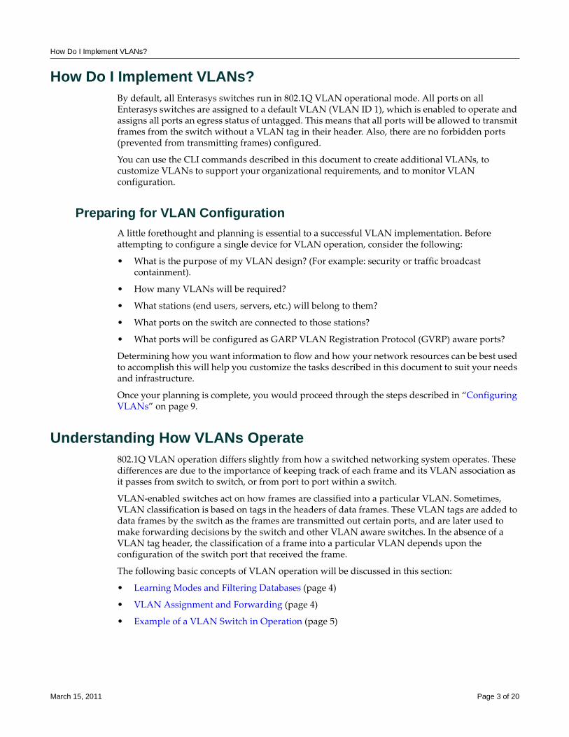
How Do I Implement VLANs?
How Do I Implement VLANs?By default, all Enterasys switches run in 802.1Q VLAN operational mode. All ports on all Enterasys switches are assigned to a default VLAN (VLAN ID 1), which is enabled to operate and assigns all ports an egress status of untagged. This means that all ports will be allowed to transmit frames from the switch without a VLAN tag in their header. Also, there are no forbidden ports (prevented from transmitting frames) configured.
You can use the CLI commands described in this document to create additional VLANs, to customize VLANs to support your organizational requirements, and to monitor VLAN configuration.
Preparing for VLAN ConfigurationA little forethought and planning is essential to a successful VLAN implementation. Before attempting to configure a single device for VLAN operation, consider the following:
• What is the purpose of my VLAN design? (For example: security or traffic broadcast containment).
• How many VLANs will be required?
• What stations (end users, servers, etc.) will belong to them?
• What ports on the switch are connected to those stations?
• What ports will be configured as GARP VLAN Registration Protocol (GVRP) aware ports?
Determining how you want information to flow and how your network resources can be best used to accomplish this will help you customize the tasks described in this document to suit your needs and infrastructure.
Once your planning is complete, you would proceed through the steps described in “Configuring VLANs” on page 9.
Understanding How VLANs Operate802.1Q VLAN operation differs slightly from how a switched networking system operates. These differences are due to the importance of keeping track of each frame and its VLAN association as it passes from switch to switch, or from port to port within a switch.
VLAN‐enabled switches act on how frames are classified into a particular VLAN. Sometimes, VLAN classification is based on tags in the headers of data frames. These VLAN tags are added to data frames by the switch as the frames are transmitted out certain ports, and are later used to make forwarding decisions by the switch and other VLAN aware switches. In the absence of a VLAN tag header, the classification of a frame into a particular VLAN depends upon the configuration of the switch port that received the frame.
The following basic concepts of VLAN operation will be discussed in this section:
• Learning Modes and Filtering Databases (page 4)
• VLAN Assignment and Forwarding (page 4)
• Example of a VLAN Switch in Operation (page 5)
March 15, 2011 Page 3 of 20
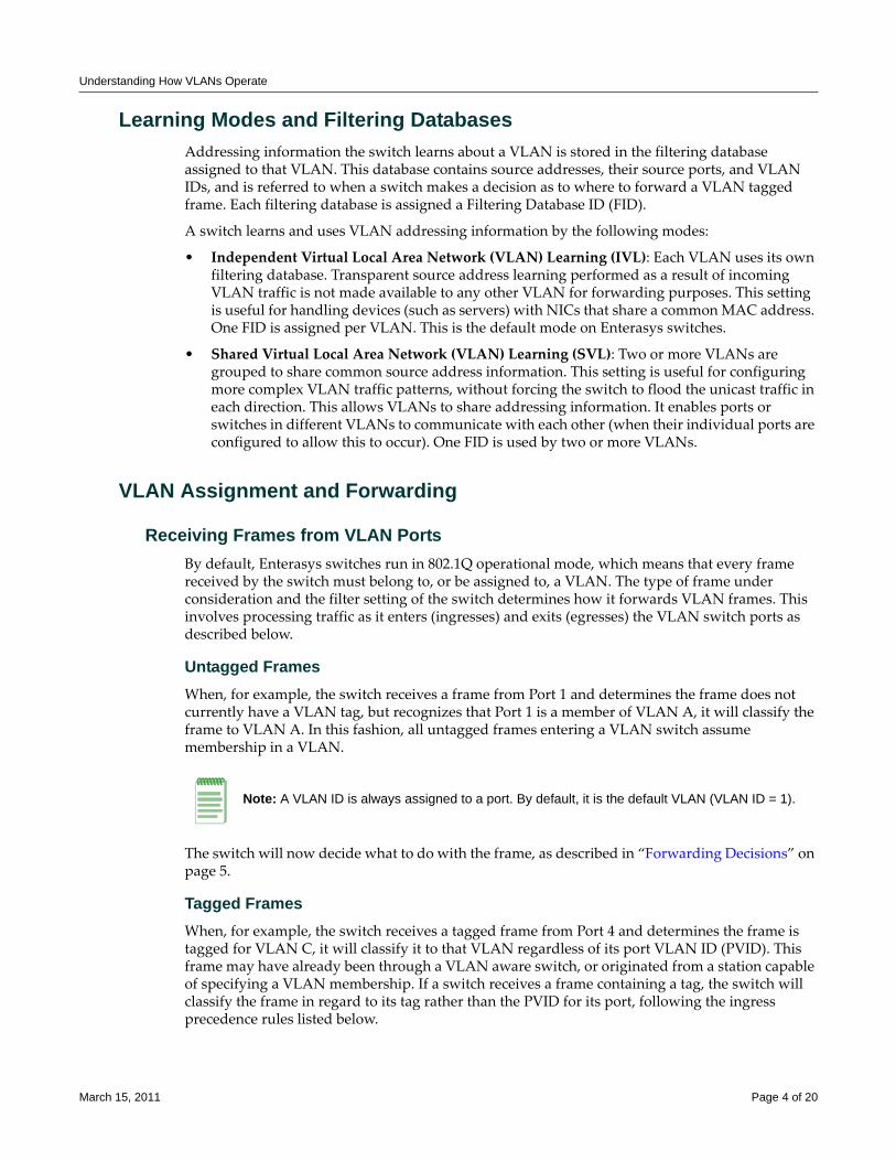
Understanding How VLANs Operate
Learning Modes and Filtering DatabasesAddressing information the switch learns about a VLAN is stored in the filtering database assigned to that VLAN. This database contains source addresses, their source ports, and VLAN IDs, and is referred to when a switch makes a decision as to where to forward a VLAN tagged frame. Each filtering database is assigned a Filtering Database ID (FID).
A switch learns and uses VLAN addressing information by the following modes:
• Independent Virtual Local Area Network (VLAN) Learning (IVL): Each VLAN uses its own filtering database. Transparent source address learning performed as a result of incoming VLAN traffic is not made available to any other VLAN for forwarding purposes. This setting is useful for handling devices (such as servers) with NICs that share a common MAC address. One FID is assigned per VLAN. This is the default mode on Enterasys switches.
• Shared Virtual Local Area Network (VLAN) Learning (SVL): Two or more VLANs are grouped to share common source address information. This setting is useful for configuring more complex VLAN traffic patterns, without forcing the switch to flood the unicast traffic in each direction. This allows VLANs to share addressing information. It enables ports or switches in different VLANs to communicate with each other (when their individual ports are configured to allow this to occur). One FID is used by two or more VLANs.
VLAN Assignment and Forwarding
Receiving Frames from VLAN PortsBy default, Enterasys switches run in 802.1Q operational mode, which means that every frame received by the switch must belong to, or be assigned to, a VLAN. The type of frame under consideration and the filter setting of the switch determines how it forwards VLAN frames. This involves processing traffic as it enters (ingresses) and exits (egresses) the VLAN switch ports as described below.
Untagged FramesWhen, for example, the switch receives a frame from Port 1 and determines the frame does not currently have a VLAN tag, but recognizes that Port 1 is a member of VLAN A, it will classify the frame to VLAN A. In this fashion, all untagged frames entering a VLAN switch assume membership in a VLAN.
The switch will now decide what to do with the frame, as described in “Forwarding Decisions” on page 5.
Tagged FramesWhen, for example, the switch receives a tagged frame from Port 4 and determines the frame is tagged for VLAN C, it will classify it to that VLAN regardless of its port VLAN ID (PVID). This frame may have already been through a VLAN aware switch, or originated from a station capable of specifying a VLAN membership. If a switch receives a frame containing a tag, the switch will classify the frame in regard to its tag rather than the PVID for its port, following the ingress precedence rules listed below.
Note: A VLAN ID is always assigned to a port. By default, it is the default VLAN (VLAN ID = 1).
March 15, 2011 Page 4 of 20
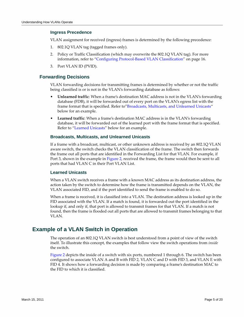
Understanding How VLANs Operate
Ingress PrecedenceVLAN assignment for received (ingress) frames is determined by the following precedence:
1. 802.1Q VLAN tag (tagged frames only).
2. Policy or Traffic Classification (which may overwrite the 802.1Q VLAN tag). For more information, refer to “Configuring Protocol‐Based VLAN Classification” on page 16.
3. Port VLAN ID (PVID).
Forwarding DecisionsVLAN forwarding decisions for transmitting frames is determined by whether or not the traffic being classified is or is not in the VLAN’s forwarding database as follows:
• Unlearned traffic: When a frame’s destination MAC address is not in the VLAN’s forwarding database (FDB), it will be forwarded out of every port on the VLAN’s egress list with the frame format that is specified. Refer to”Broadcasts, Multicasts, and Unlearned Unicasts“ below for an example.
• Learned traffic: When a frame’s destination MAC address is in the VLAN’s forwarding database, it will be forwarded out of the learned port with the frame format that is specified. Refer to “Learned Unicasts” below for an example.
Broadcasts, Multicasts, and Unlearned UnicastsIf a frame with a broadcast, multicast, or other unknown address is received by an 802.1Q VLAN aware switch, the switch checks the VLAN classification of the frame. The switch then forwards the frame out all ports that are identified in the Forwarding List for that VLAN. For example, if Port 3, shown in the example in Figure 2, received the frame, the frame would then be sent to all ports that had VLAN C in their Port VLAN List.
Learned UnicastsWhen a VLAN switch receives a frame with a known MAC address as its destination address, the action taken by the switch to determine how the frame is transmitted depends on the VLAN, the VLAN associated FID, and if the port identified to send the frame is enabled to do so.
When a frame is received, it is classified into a VLAN. The destination address is looked up in the FID associated with the VLAN. If a match is found, it is forwarded out the port identified in the lookup if, and only if, that port is allowed to transmit frames for that VLAN. If a match is not found, then the frame is flooded out all ports that are allowed to transmit frames belonging to that VLAN.
Example of a VLAN Switch in OperationThe operation of an 802.1Q VLAN switch is best understood from a point of view of the switch itself. To illustrate this concept, the examples that follow view the switch operations from inside the switch.
Figure 2 depicts the inside of a switch with six ports, numbered 1 through 6. The switch has been configured to associate VLAN A and B with FID 2, VLAN C and D with FID 3, and VLAN E with FID 4. It shows how a forwarding decision is made by comparing a frame’s destination MAC to the FID to which it is classified.
March 15, 2011 Page 5 of 20
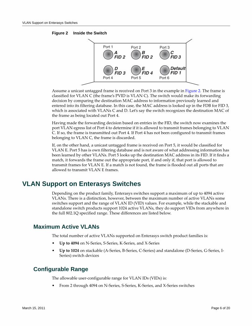
VLAN Support on Enterasys Switches
Figure 2 Inside the Switch
Assume a unicast untagged frame is received on Port 3 in the example in Figure 2. The frame is classified for VLAN C (the frame’s PVID is VLAN C). The switch would make its forwarding decision by comparing the destination MAC address to information previously learned and entered into its filtering database. In this case, the MAC address is looked up in the FDB for FID 3, which is associated with VLANs C and D. Let’s say the switch recognizes the destination MAC of the frame as being located out Port 4.
Having made the forwarding decision based on entries in the FID, the switch now examines the port VLAN egress list of Port 4 to determine if it is allowed to transmit frames belonging to VLAN C. If so, the frame is transmitted out Port 4. If Port 4 has not been configured to transmit frames belonging to VLAN C, the frame is discarded.
If, on the other hand, a unicast untagged frame is received on Port 5, it would be classified for VLAN E. Port 5 has is own filtering database and is not aware of what addressing information has been learned by other VLANs. Port 5 looks up the destination MAC address in its FID. If it finds a match, it forwards the frame out the appropriate port, if and only if, that port is allowed to transmit frames for VLAN E. If a match is not found, the frame is flooded out all ports that are allowed to transmit VLAN E frames.
VLAN Support on Enterasys SwitchesDepending on the product family, Enterasys switches support a maximum of up to 4094 active VLANs. There is a distinction, however, between the maximum number of active VLANs some switches support and the range of VLAN ID (VID) values. For example, while the stackable and standalone switch products support 1024 active VLANs, they do support VIDs from anywhere in the full 802.1Q specified range. These differences are listed below.
Maximum Active VLANsThe total number of active VLANs supported on Enterasys switch product families is:
• Up to 4094 on N‐Series, S‐Series, K‐Series, and X‐Series
• Up to 1024 on stackable (A‐Series, B‐Series, C‐Series) and standalone (D‐Series, G‐Series, I‐Series) switch devices
Configurable RangeThe allowable user‐configurable range for VLAN IDs (VIDs) is:
• From 2 through 4094 on N‐Series, S‐Series, K‐Series, and X‐Series switches
�����
������
�����������
�����
����������
�����
����
��� ��������
�����
������
March 15, 2011 Page 6 of 20
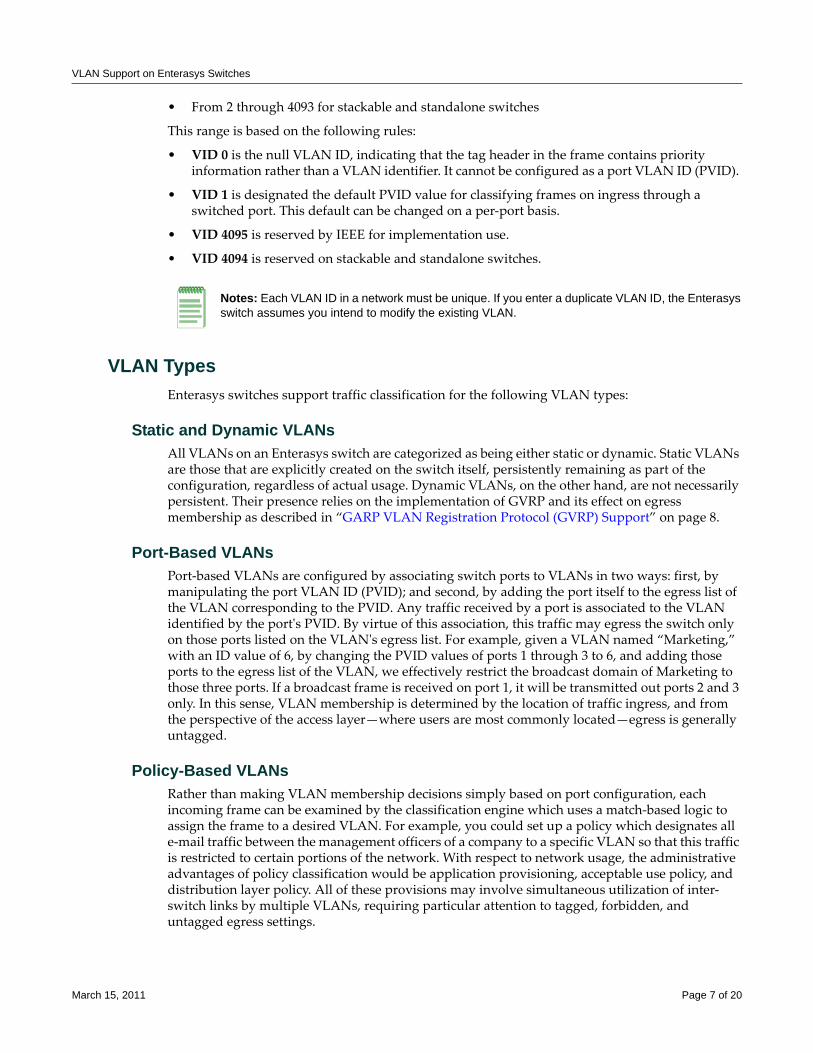
VLAN Support on Enterasys Switches
• From 2 through 4093 for stackable and standalone switches
This range is based on the following rules:
• VID 0 is the null VLAN ID, indicating that the tag header in the frame contains priority information rather than a VLAN identifier. It cannot be configured as a port VLAN ID (PVID).
• VID 1 is designated the default PVID value for classifying frames on ingress through a switched port. This default can be changed on a per‐port basis.
• VID 4095 is reserved by IEEE for implementation use.
• VID 4094 is reserved on stackable and standalone switches.
VLAN TypesEnterasys switches support traffic classification for the following VLAN types:
Static and Dynamic VLANsAll VLANs on an Enterasys switch are categorized as being either static or dynamic. Static VLANs are those that are explicitly created on the switch itself, persistently remaining as part of the configuration, regardless of actual usage. Dynamic VLANs, on the other hand, are not necessarily persistent. Their presence relies on the implementation of GVRP and its effect on egress membership as described in “GARP VLAN Registration Protocol (GVRP) Support” on page 8.
Port-Based VLANsPort‐based VLANs are configured by associating switch ports to VLANs in two ways: first, by manipulating the port VLAN ID (PVID); and second, by adding the port itself to the egress list of the VLAN corresponding to the PVID. Any traffic received by a port is associated to the VLAN identified by the portʹs PVID. By virtue of this association, this traffic may egress the switch only on those ports listed on the VLANʹs egress list. For example, given a VLAN named “Marketing,” with an ID value of 6, by changing the PVID values of ports 1 through 3 to 6, and adding those ports to the egress list of the VLAN, we effectively restrict the broadcast domain of Marketing to those three ports. If a broadcast frame is received on port 1, it will be transmitted out ports 2 and 3 only. In this sense, VLAN membership is determined by the location of traffic ingress, and from the perspective of the access layer—where users are most commonly located—egress is generally untagged.
Policy-Based VLANsRather than making VLAN membership decisions simply based on port configuration, each incoming frame can be examined by the classification engine which uses a match‐based logic to assign the frame to a desired VLAN. For example, you could set up a policy which designates all e‐mail traffic between the management officers of a company to a specific VLAN so that this traffic is restricted to certain portions of the network. With respect to network usage, the administrative advantages of policy classification would be application provisioning, acceptable use policy, and distribution layer policy. All of these provisions may involve simultaneous utilization of inter‐switch links by multiple VLANs, requiring particular attention to tagged, forbidden, and untagged egress settings.
Notes: Each VLAN ID in a network must be unique. If you enter a duplicate VLAN ID, the Enterasys switch assumes you intend to modify the existing VLAN.
March 15, 2011 Page 7 of 20
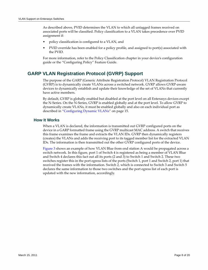
VLAN Support on Enterasys Switches
As described above, PVID determines the VLAN to which all untagged frames received on associated ports will be classified. Policy classification to a VLAN takes precedence over PVID assignment if:
• policy classification is configured to a VLAN, and
• PVID override has been enabled for a policy profile, and assigned to port(s) associated with the PVID.
For more information, refer to the Policy Classification chapter in your device’s configuration guide or the “Configuring Policy” Feature Guide.
GARP VLAN Registration Protocol (GVRP) SupportThe purpose of the GARP (Generic Attribute Registration Protocol) VLAN Registration Protocol (GVRP) is to dynamically create VLANs across a switched network. GVRP allows GVRP‐aware devices to dynamically establish and update their knowledge of the set of VLANs that currently have active members.
By default, GVRP is globally enabled but disabled at the port level on all Enterasys devices except the N‐Series. On the N‐Series, GVRP is enabled globally and at the port level. To allow GVRP to dynamically create VLANs, it must be enabled globally and also on each individual port as described in “Configuring Dynamic VLANs” on page 15.
How It WorksWhen a VLAN is declared, the information is transmitted out GVRP configured ports on the device in a GARP formatted frame using the GVRP multicast MAC address. A switch that receives this frame examines the frame and extracts the VLAN IDs. GVRP then dynamically registers (creates) the VLANs and adds the receiving port to its tagged member list for the extracted VLAN IDs. The information is then transmitted out the other GVRP configured ports of the device.
Figure 3 shows an example of how VLAN Blue from end station A would be propagated across a switch network. In this figure, port 1 of Switch 4 is registered as being a member of VLAN Blue and Switch 4 declares this fact out all its ports (2 and 3) to Switch 1 and Switch 2. These two switches register this in the port egress lists of the ports (Switch 1, port 1 and Switch 2, port 1) that received the frames with the information. Switch 2, which is connected to Switch 3 and Switch 5 declares the same information to those two switches and the port egress list of each port is updated with the new information, accordingly.
March 15, 2011 Page 8 of 20
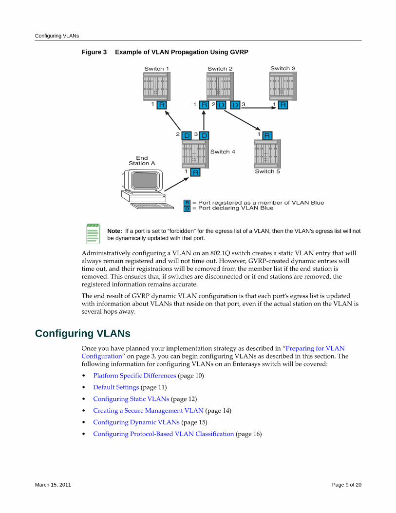
Configuring VLANs
Figure 3 Example of VLAN Propagation Using GVRP
Administratively configuring a VLAN on an 802.1Q switch creates a static VLAN entry that will always remain registered and will not time out. However, GVRP‐created dynamic entries will time out, and their registrations will be removed from the member list if the end station is removed. This ensures that, if switches are disconnected or if end stations are removed, the registered information remains accurate.
The end result of GVRP dynamic VLAN configuration is that each port’s egress list is updated with information about VLANs that reside on that port, even if the actual station on the VLAN is several hops away.
Configuring VLANsOnce you have planned your implementation strategy as described in “Preparing for VLAN Configuration” on page 3, you can begin configuring VLANs as described in this section. The following information for configuring VLANs on an Enterasys switch will be covered:
• Platform Specific Differences (page 10)
• Default Settings (page 11)
• Configuring Static VLANs (page 12)
• Creating a Secure Management VLAN (page 14)
• Configuring Dynamic VLANs (page 15)
• Configuring Protocol‐Based VLAN Classification (page 16)
Note: If a port is set to “forbidden” for the egress list of a VLAN, then the VLAN’s egress list will not be dynamically updated with that port.
/�!��������0
�%��'(��
�%��'(��
1� �������������!������&�&+����,�230-�"�#�1� ����!�'�������230-�"�#��
�
�
�� � 6
6
�
�� � 6 6 �
�%��'(�� �%��'(�� �%��'(��
March 15, 2011 Page 9 of 20
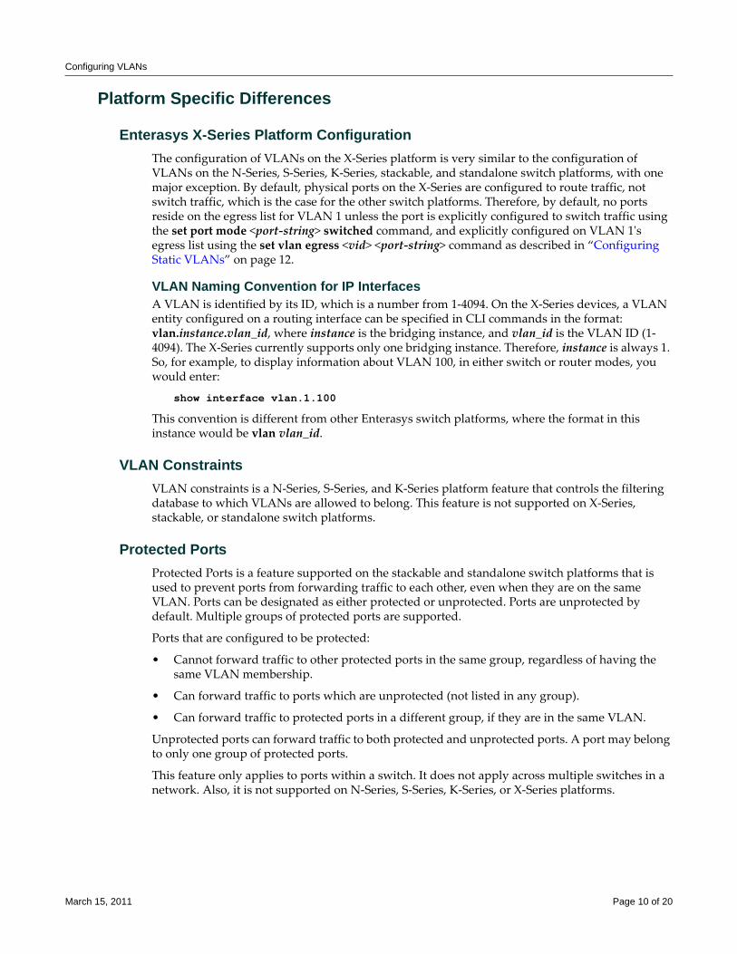
Configuring VLANs
Platform Specific Differences
Enterasys X-Series Platform ConfigurationThe configuration of VLANs on the X‐Series platform is very similar to the configuration of VLANs on the N‐Series, S‐Series, K‐Series, stackable, and standalone switch platforms, with one major exception. By default, physical ports on the X‐Series are configured to route traffic, not switch traffic, which is the case for the other switch platforms. Therefore, by default, no ports reside on the egress list for VLAN 1 unless the port is explicitly configured to switch traffic using the set port mode <port‐string> switched command, and explicitly configured on VLAN 1ʹs egress list using the set vlan egress <vid> <port‐string> command as described in “Configuring Static VLANs” on page 12.
VLAN Naming Convention for IP InterfacesA VLAN is identified by its ID, which is a number from 1‐4094. On the X‐Series devices, a VLAN entity configured on a routing interface can be specified in CLI commands in the format: vlan.instance.vlan_id, where instance is the bridging instance, and vlan_id is the VLAN ID (1‐4094). The X‐Series currently supports only one bridging instance. Therefore, instance is always 1. So, for example, to display information about VLAN 100, in either switch or router modes, you would enter:
show interface vlan.1.100
This convention is different from other Enterasys switch platforms, where the format in this instance would be vlan vlan_id.
VLAN ConstraintsVLAN constraints is a N‐Series, S‐Series, and K‐Series platform feature that controls the filtering database to which VLANs are allowed to belong. This feature is not supported on X‐Series, stackable, or standalone switch platforms.
Protected PortsProtected Ports is a feature supported on the stackable and standalone switch platforms that is used to prevent ports from forwarding traffic to each other, even when they are on the same VLAN. Ports can be designated as either protected or unprotected. Ports are unprotected by default. Multiple groups of protected ports are supported.
Ports that are configured to be protected:
• Cannot forward traffic to other protected ports in the same group, regardless of having the same VLAN membership.
• Can forward traffic to ports which are unprotected (not listed in any group).
• Can forward traffic to protected ports in a different group, if they are in the same VLAN.
Unprotected ports can forward traffic to both protected and unprotected ports. A port may belong to only one group of protected ports.
This feature only applies to ports within a switch. It does not apply across multiple switches in a network. Also, it is not supported on N‐Series, S‐Series, K‐Series, or X‐Series platforms.
March 15, 2011 Page 10 of 20
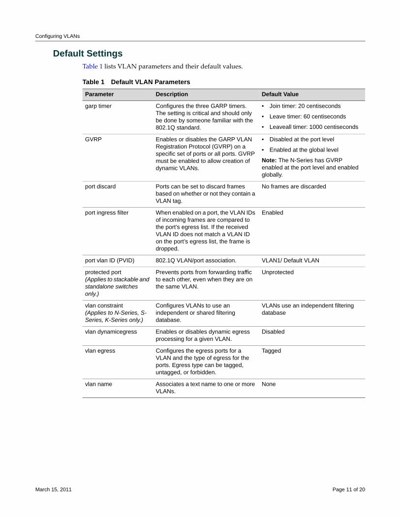
Configuring VLANs
Default SettingsTable 1 lists VLAN parameters and their default values.
Table 1 Default VLAN Parameters
Parameter Description Default Value
garp timer Configures the three GARP timers. The setting is critical and should only be done by someone familiar with the 802.1Q standard.
• Join timer: 20 centiseconds
• Leave timer: 60 centiseconds
• Leaveall timer: 1000 centiseconds
GVRP Enables or disables the GARP VLAN Registration Protocol (GVRP) on a specific set of ports or all ports. GVRP must be enabled to allow creation of dynamic VLANs.
• Disabled at the port level
• Enabled at the global level
Note: The N-Series has GVRP enabled at the port level and enabled globally.
port discard Ports can be set to discard frames based on whether or not they contain a VLAN tag.
No frames are discarded
port ingress filter When enabled on a port, the VLAN IDs of incoming frames are compared to the port’s egress list. If the received VLAN ID does not match a VLAN ID on the port’s egress list, the frame is dropped.
Enabled
port vlan ID (PVID) 802.1Q VLAN/port association. VLAN1/ Default VLAN
protected port(Applies to stackable and standalone switches only.)
Prevents ports from forwarding traffic to each other, even when they are on the same VLAN.
Unprotected
vlan constraint (Applies to N-Series, S-Series, K-Series only.)
Configures VLANs to use an independent or shared filtering database.
VLANs use an independent filtering database
vlan dynamicegress Enables or disables dynamic egress processing for a given VLAN.
Disabled
vlan egress Configures the egress ports for a VLAN and the type of egress for the ports. Egress type can be tagged, untagged, or forbidden.
Tagged
vlan name Associates a text name to one or more VLANs.
None
March 15, 2011 Page 11 of 20
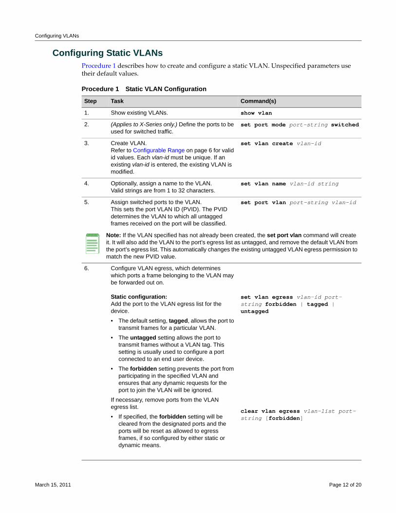
Configuring VLANs
Configuring Static VLANsProcedure 1 describes how to create and configure a static VLAN. Unspecified parameters use their default values.
Procedure 1 Static VLAN Configuration
Step Task Command(s)
1. Show existing VLANs. show vlan
2. (Applies to X-Series only.) Define the ports to be used for switched traffic.
set port mode port-string switched
3. Create VLAN. Refer to Configurable Range on page 6 for valid id values. Each vlan-id must be unique. If an existing vlan-id is entered, the existing VLAN is modified.
set vlan create vlan-id
4. Optionally, assign a name to the VLAN. Valid strings are from 1 to 32 characters.
set vlan name vlan-id string
5. Assign switched ports to the VLAN. This sets the port VLAN ID (PVID). The PVID determines the VLAN to which all untagged frames received on the port will be classified.
set port vlan port-string vlan-id
Note: If the VLAN specified has not already been created, the set port vlan command will create it. It will also add the VLAN to the port’s egress list as untagged, and remove the default VLAN from the port’s egress list. This automatically changes the existing untagged VLAN egress permission to match the new PVID value.
6. Configure VLAN egress, which determines which ports a frame belonging to the VLAN may be forwarded out on.
Static configuration:Add the port to the VLAN egress list for the device.
• The default setting, tagged, allows the port to transmit frames for a particular VLAN.
• The untagged setting allows the port to transmit frames without a VLAN tag. This setting is usually used to configure a port connected to an end user device.
• The forbidden setting prevents the port from participating in the specified VLAN and ensures that any dynamic requests for the port to join the VLAN will be ignored.
If necessary, remove ports from the VLAN egress list.
• If specified, the forbidden setting will be cleared from the designated ports and the ports will be reset as allowed to egress frames, if so configured by either static or dynamic means.
set vlan egress vlan-id port-string forbidden | tagged | untagged
clear vlan egress vlan-list port-string [forbidden]
March 15, 2011 Page 12 of 20
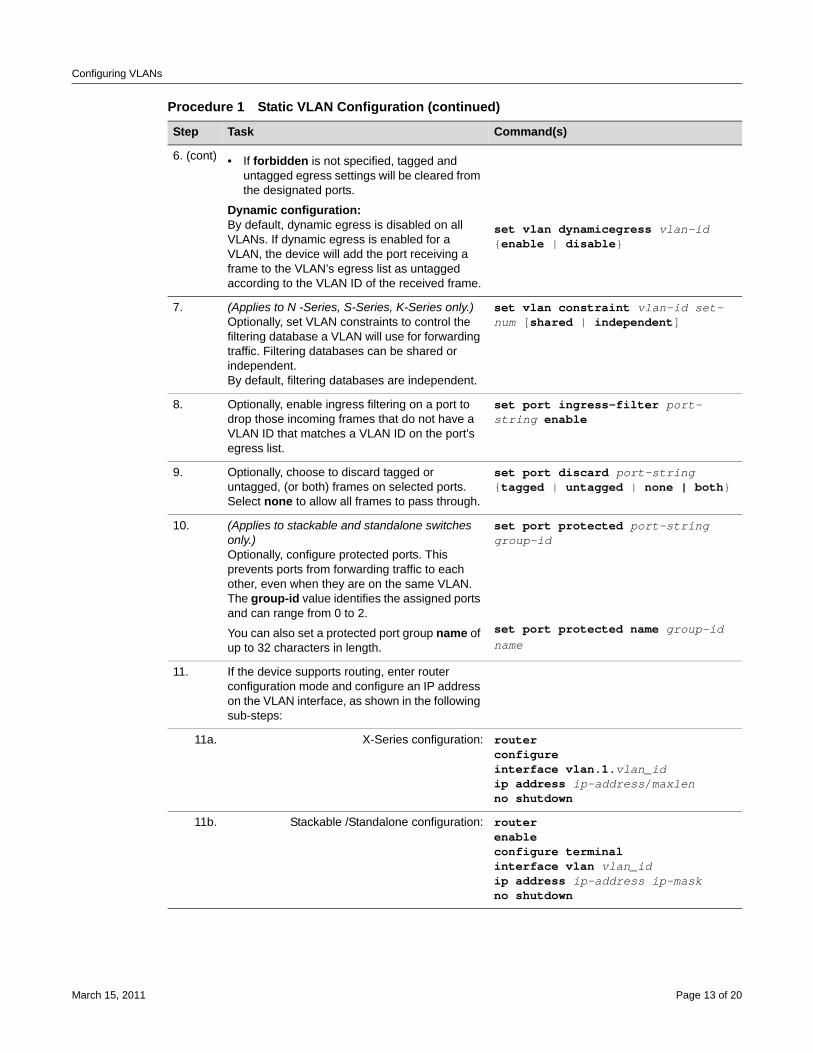
Configuring VLANs
6. (cont) • If forbidden is not specified, tagged and untagged egress settings will be cleared from the designated ports.
Dynamic configuration:By default, dynamic egress is disabled on all VLANs. If dynamic egress is enabled for a VLAN, the device will add the port receiving a frame to the VLAN’s egress list as untagged according to the VLAN ID of the received frame.
set vlan dynamicegress vlan-id {enable | disable}
7. (Applies to N -Series, S-Series, K-Series only.) Optionally, set VLAN constraints to control the filtering database a VLAN will use for forwarding traffic. Filtering databases can be shared or independent.By default, filtering databases are independent.
set vlan constraint vlan-id set-num [shared | independent]
8. Optionally, enable ingress filtering on a port to drop those incoming frames that do not have a VLAN ID that matches a VLAN ID on the port’s egress list.
set port ingress-filter port-string enable
9. Optionally, choose to discard tagged or untagged, (or both) frames on selected ports.Select none to allow all frames to pass through.
set port discard port-string {tagged | untagged | none | both}
10. (Applies to stackable and standalone switches only.) Optionally, configure protected ports. This prevents ports from forwarding traffic to each other, even when they are on the same VLAN.The group-id value identifies the assigned ports and can range from 0 to 2.
You can also set a protected port group name of up to 32 characters in length.
set port protected port-string group-id
set port protected name group-id name
11. If the device supports routing, enter router configuration mode and configure an IP address on the VLAN interface, as shown in the following sub-steps:
11a. X-Series configuration: routerconfigureinterface vlan.1.vlan_idip address ip-address/maxlenno shutdown
11b. Stackable /Standalone configuration: routerenableconfigure terminalinterface vlan vlan_idip address ip-address ip-maskno shutdown
Procedure 1 Static VLAN Configuration (continued)
Step Task Command(s)
March 15, 2011 Page 13 of 20
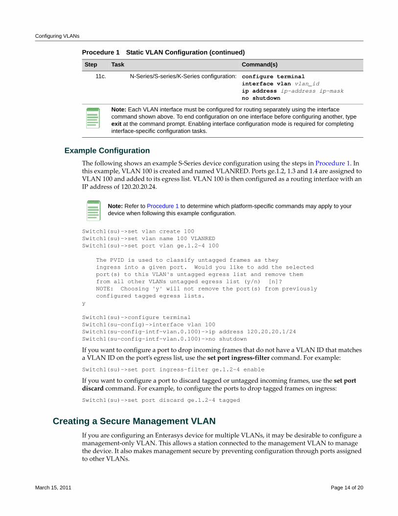
Configuring VLANs
Example ConfigurationThe following shows an example S‐Series device configuration using the steps in Procedure 1. In this example, VLAN 100 is created and named VLANRED. Ports ge.1.2, 1.3 and 1.4 are assigned to VLAN 100 and added to its egress list. VLAN 100 is then configured as a routing interface with an IP address of 120.20.20.24.
Switch1(su)->set vlan create 100Switch1(su)->set vlan name 100 VLANREDSwitch1(su)->set port vlan ge.1.2-4 100
The PVID is used to classify untagged frames as they ingress into a given port. Would you like to add the selected port(s) to this VLAN's untagged egress list and remove them from all other VLANs untagged egress list (y/n) [n]? NOTE: Choosing 'y' will not remove the port(s) from previously configured tagged egress lists.y
Switch1(su)->configure terminalSwitch1(su-config)->interface vlan 100Switch1(su-config-intf-vlan.0.100)->ip address 120.20.20.1/24Switch1(su-config-intf-vlan.0.100)->no shutdown
If you want to configure a port to drop incoming frames that do not have a VLAN ID that matches a VLAN ID on the port’s egress list, use the set port ingress‐filter command. For example:
Switch1(su)->set port ingress-filter ge.1.2-4 enable
If you want to configure a port to discard tagged or untagged incoming frames, use the set port discard command. For example, to configure the ports to drop tagged frames on ingress:
Switch1(su)->set port discard ge.1.2-4 tagged
Creating a Secure Management VLANIf you are configuring an Enterasys device for multiple VLANs, it may be desirable to configure a management‐only VLAN. This allows a station connected to the management VLAN to manage the device. It also makes management secure by preventing configuration through ports assigned to other VLANs.
11c. N-Series/S-series/K-Series configuration: configure terminalinterface vlan vlan_idip address ip-address ip-maskno shutdown
Note: Each VLAN interface must be configured for routing separately using the interface command shown above. To end configuration on one interface before configuring another, type exit at the command prompt. Enabling interface configuration mode is required for completing interface-specific configuration tasks.
Procedure 1 Static VLAN Configuration (continued)
Step Task Command(s)
Note: Refer to Procedure 1 to determine which platform-specific commands may apply to your device when following this example configuration.
March 15, 2011 Page 14 of 20
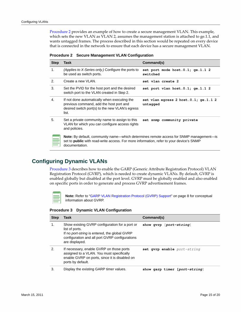
Configuring VLANs
Procedure 2 provides an example of how to create a secure management VLAN. This example, which sets the new VLAN as VLAN 2, assumes the management station is attached to ge.1.1, and wants untagged frames. The process described in this section would be repeated on every device that is connected in the network to ensure that each device has a secure management VLAN. .
Configuring Dynamic VLANsProcedure 3 describes how to enable the GARP (Generic Attribute Registration Protocol) VLAN Registration Protocol (GVRP), which is needed to create dynamic VLANs. By default, GVRP is enabled globally but disabled at the port level. GVRP must be globally enabled and also enabled on specific ports in order to generate and process GVRP advertisement frames.
Procedure 2 Secure Management VLAN Configuration
Step Task Command(s)
1. (Applies to X-Series only.) Configure the ports to be used as switch ports.
set port mode host.0.1; ge.1.1 2 switched
2. Create a new VLAN. set vlan create 2
3. Set the PVID for the host port and the desired switch port to the VLAN created in Step 2.
set port vlan host.0.1; ge.1.1 2
4. If not done automatically when executing the previous command, add the host port and desired switch port(s) to the new VLAN’s egress list.
set vlan egress 2 host.0.1; ge.1.1 2 untagged
5. Set a private community name to assign to this VLAN for which you can configure access rights and policies.
set snmp community private
Note: By default, community name—which determines remote access for SNMP management—is set to public with read-write access. For more information, refer to your device’s SNMP documentation.
Note: Refer to “GARP VLAN Registration Protocol (GVRP) Support” on page 8 for conceptual information about GVRP.
Procedure 3 Dynamic VLAN Configuration
Step Task Command(s)
1. Show existing GVRP configuration for a port or list of ports. If no port-string is entered, the global GVRP configuration and all port GVRP configurations are displayed.
show gvrp [port-string]
2. If necessary, enable GVRP on those ports assigned to a VLAN. You must specifically enable GVRP on ports, since it is disabled on ports by default.
set gvrp enable port-string
3. Display the existing GARP timer values. show garp timer [port-string]
March 15, 2011 Page 15 of 20
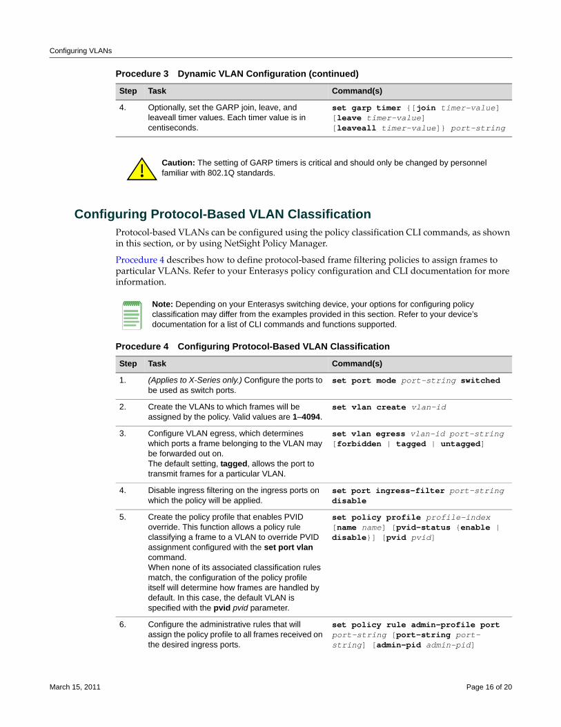
Configuring VLANs
Configuring Protocol-Based VLAN ClassificationProtocol‐based VLANs can be configured using the policy classification CLI commands, as shown in this section, or by using NetSight Policy Manager.
Procedure 4 describes how to define protocol‐based frame filtering policies to assign frames to particular VLANs. Refer to your Enterasys policy configuration and CLI documentation for more information.
4. Optionally, set the GARP join, leave, and leaveall timer values. Each timer value is in centiseconds.
set garp timer {[join timer-value] [leave timer-value] [leaveall timer-value]} port-string
Caution: The setting of GARP timers is critical and should only be changed by personnel familiar with 802.1Q standards.
Procedure 3 Dynamic VLAN Configuration (continued)
Step Task Command(s)
Note: Depending on your Enterasys switching device, your options for configuring policy classification may differ from the examples provided in this section. Refer to your device’s documentation for a list of CLI commands and functions supported.
Procedure 4 Configuring Protocol-Based VLAN Classification
Step Task Command(s)
1. (Applies to X-Series only.) Configure the ports to be used as switch ports.
set port mode port-string switched
2. Create the VLANs to which frames will be assigned by the policy. Valid values are 1–4094.
set vlan create vlan-id
3. Configure VLAN egress, which determines which ports a frame belonging to the VLAN may be forwarded out on.The default setting, tagged, allows the port to transmit frames for a particular VLAN.
set vlan egress vlan-id port-string [forbidden | tagged | untagged]
4. Disable ingress filtering on the ingress ports on which the policy will be applied.
set port ingress-filter port-string disable
5. Create the policy profile that enables PVID override. This function allows a policy rule classifying a frame to a VLAN to override PVID assignment configured with the set port vlan command.When none of its associated classification rules match, the configuration of the policy profile itself will determine how frames are handled by default. In this case, the default VLAN is specified with the pvid pvid parameter.
set policy profile profile-index [name name] [pvid-status {enable | disable}] [pvid pvid]
6. Configure the administrative rules that will assign the policy profile to all frames received on the desired ingress ports.
set policy rule admin-profile port port-string [port-string port-string] [admin-pid admin-pid]
March 15, 2011 Page 16 of 20
Configuring VLANs
Example ConfigurationThe following shows an example N‐Series device configuration using the steps in Procedure 4. This example configures a policy that ensures that IP traffic received on the specified ingress ports will be mapped to VLAN 2, while all other types of traffic will be mapped to VLAN 3.
1. Two VLANs are created: VLAN 2 and VLAN 3.
2. Ports 1 through 5 on the Gigabit Ethernet module in slot 4 are configured as egress ports for the VLANs while ports 8 through 10 on the Gigabit Ethernet module in slot 5 are configured as ingress ports that will do the policy classification.
3. Policy profile number 1 is created that enables PVID override and defines the default behavior (classify to VLAN 3) if none of the classification rules created for the profile are matched.
4. Administrative rules are created that apply policy profile number 1 to all frames received on the ingress ports ge.5.8 through 10.
5. Classification rules are created for policy profile number 1 that assign IP frames to VLAN 2. The rules identify IP frames by using the ether protocol parameter, which classifies on the Type field in the headers of Layer 2 Ethernet II frames, and the protocol data of 0x0800 (IP type), 0x0806 (ARP type), and 0x8035 (RARP type).
Switch1(su)->set vlan create 2, 3Switch1(su)->set vlan egress 2 ge.4.1-2 Switch1(su)->set vlan egress 3 ge.4.3-5Switch1(su)->set port ingress-filter ge.5.8-10 disableSwitch1(su)->set policy profile 1 name protocol_based_vlan pvid-status enable
pvid 3Switch1(su)->set policy rule admin-profile port ge.5.8 port-string ge.5.8
admin-pid 1Switch1(su)->set policy rule admin-profile port ge.5.9 port-string ge.5.9
admin-pid 1Switch1(su)->set policy rule admin-profile port ge.5.10 port-string ge.5.10
admin-pid 1Switch1(su)->set policy rule 1 ether 0x0800 mask 16 vlan 2Switch1(su)->set policy rule 1 ether 0x0806 mask 16 vlan 2Switch1(su)->set policy rule 1 ether 0x8035 mask 16 vlan 2
Monitoring VLANsTable 2 describes the show commands that display information about VLAN configurations. Refer to your device’s CLI documentation for a description of the output of each show command.
7. Configure the classification rules that will define the protocol to filter on and the VLAN ID to which matching frames will be assigned.
set policy rule profile-index {protocol data [mask mask]} [vlan vlan]
Procedure 4 Configuring Protocol-Based VLAN Classification (continued)
Step Task Command(s)
Table 2 Displaying VLAN Information
Task Command
Display all existing VLANs. show vlan
March 15, 2011 Page 17 of 20
Terms and Definitions
Terms and DefinitionsTable 3 lists terms and definitions used in VLAN configuration.
(Applies to N-Series, S-Series, K-Series only.)Display the VLAN constraint setting.
show vlan constraint [vlan id]
Display the VLAN dynamic egress setting. show vlan dynamicegress [vlan id]
Display all static VLANs. show vlan static
Display ports assigned to VLANs. show port vlan [port-string]
Display existing GVRP settings. show gvrp [port-string]
Display static ports on the given vid, group. show igmp static [vlan id]
(Applies to stackable and standalone switches only.) Display port(s) configured in protected mode
show port protected [port-string] | [group-id]
(Applies to stackable and standalone switches only.) Display the name of a specific group of protected ports.
show port protected name group-id
Table 2 Displaying VLAN Information (continued)
Task Command
Table 3 VLAN Terms and Definitions Term Definition
Default VLAN The VLAN to which all ports are assigned upon initialization. The default VLAN has a VLAN ID of 1 and cannot be deleted or renamed.
Filtering Database A database structure within the switch that keeps track of the associations between MAC addresses, VLANs, and interface (port) numbers. The Filtering Database is referred to when a switch makes a forwarding decision on a frame.
Filtering Database Identifier (FID)
Addressing information that the device learns about a VLAN is stored in the filtering database assigned to that VLAN. Several VLANs can be assigned to the same FID to allow those VLANs to share addressing information. This enables the devices in the different VLANs to communicate with each other when the individual ports have been configured to allow communication to occur.
The configuration is accomplished using the Local Management VLAN Forwarding Configuration screen. By default a VLAN is assigned to the FID that matches its VLAN ID.
Forwarding List A list of the ports on a particular device that are eligible to transmit frames for a selected VLAN.
GARP Multicast Registration Protocol (GMRP)
A GARP application that functions in a similar fashion as GVRP, except that GMRP registers multicast addresses on ports to control the flooding of multicast frames.
GARP VLAN Registration Protocol (GVRP)
A GARP application used to dynamically create VLANs across a switched network.
March 15, 2011 Page 18 of 20
Terms and Definitions
Generic Attribute Registration Protocol (GARP)
GARP is a protocol used to propagate state information throughout a switched network.
Port VLAN List A per port list of all eligible VLANs whose frames can be forwarded out one specific port and the frame format (tagged or untagged) of transmissions for that port. The Port VLAN List specifies what VLANs are associated with a single port for frame transmission purposes.
Tag Header (VLAN Tag)
Four bytes of data inserted in a frame that identifies the VLAN/frame classification. The Tag Header is inserted into the frame directly after the Source MAC address field. Twelve bits of the Tag Header represent the VLAN ID. The remaining bits are other control information.
Tagged Frame A data frame that contains a Tag Header. A VLAN aware device can add the Tag Header to any frame it transmits.
Untagged Frame A data frame that does not have a Tag Header.
VLAN ID A unique number (between 1 and 4094) that identifies a particular VLAN.
VLAN Name A 32-character alphanumeric name associated with a VLAN ID. The VLAN Name is intended to make user-defined VLANs easier to identify and remember.
Table 3 VLAN Terms and Definitions (continued)Term Definition
March 15, 2011 Page 19 of 20
Enterasys Networks reserves the right to make changes in specifications and other information contained in this document and its web site without prior notice. The reader should in all cases consult Enterasys Networks to determine whether any such changes have been made.
The hardware, firmware, or software described in this document is subject to change without notice.
IN NO EVENT SHALL ENTERASYS NETWORKS BE LIABLE FOR ANY INCIDENTAL, INDIRECT, SPECIAL, OR CONSEQUENTIAL DAMAGES WHATSOEVER (INCLUDING BUT NOT LIMITED TO LOST PROFITS) ARISING OUT OF OR RELATED TO THIS DOCUMENT, WEB SITE, OR THE INFORMATION CONTAINED IN THEM, EVEN IF ENTERASYS NETWORKS HAS BEEN ADVISED OF, KNEW OF, OR SHOULD HAVE KNOWN OF, THE POSSIBILITY OF SUCH DAMAGES.
Enterasys Networks, Inc.50 Minuteman RoadAndover, MA 01810
© 2011 Enterasys Networks, Inc. All rights reserved.ENTERASYS, ENTERASYS NETWORKS, ENTERASYS NETSIGHT, and any logos associated therewith, are trademarks or registered trademarks of Enterasys Networks, Inc., in the United States and other countries. For a complete list of Enterasys trademarks, see http://www.enterasys.com/company/trademarks.aspx.
All other product names mentioned in this manual may be trademarks or registered trademarks of their respective companies.
Revision History
Date Description
02-01-2008 New document.
02-20-2008 Corrected product naming conventions.
07-28-2008 Modifications due to product rebranding changes.
01-07-2009 Corrected error in configuration example.
03-15-2011 Added S-Series and K-Series. Removed IGMP snooping (covered in Multicast Feature Guide).