Embed Size (px)
Citation preview
Feasibility Studyfor
XCHANGE TELECOMDecember 18, 2009
Fiber to the Home InitiativeBoro Park, Brooklyn NY

Boro Park Feasibility Study Fiber –To-The -Home
Table of Contents
I. Cover
II. Table of Contents
III. Executive Summary A. IntroductionB. Project Understanding C. Company Information
IV. Design, Engineering and Project Management Requirements
A. Design and Mapping Approach B. As-Built Drawings C. Field Survey
1. Existing Utility Locates/Research 2. New Underground Conduit Design 3. Existing Electrical Conduit Design 4. Aerial Design
D. Design Topology 1. Network Overview 2. Node Facilities 3. Main Backbone 4. Easement Laterals 5. Customer Fiber Drop
E. Make Ready Work (Verizon and CATV) F. Project Management and Construction Coordination G. SubcontractorsH. Fiber Management I. Restoration J. Fiber Splicing and Testing
1. Fusion Splicing Procedures i. Cable Preparation
ii. Fiber Preparation and Fusion Splicing iii. Cable/Splice Housing Final Storage
2. Testing Procedures K. Permitting and Right-of-Way Requirements L. Traffic Control Plans
V. Service Installation Requirements A. House Drop Service Work B. In-House Wiring and Activation Work
VI. Staffing Considerations
VII. Upstream Broadband Link Considerations

Boro Park Feasibility Study Fiber –To-The -Home
VIII. Business Plan Financial Analysis
IX. Appendices
III. Executive Summary
A. Introduction
On behalf of Matrix Design Group, I wish to thank you for extending us the opportunity to submit this Feasibility Study to XChange Telecom in support of your Fiber-To-The-Home initiative. Attached, please find the conceptual description and understanding that we have of a section of Boro Park Brooklyn and goal to achieve an optical network that will satisfy the needs of the residents of Boro Park.
We have joined together an outstanding team that has extensive experience in network design and construction, as well as a strong reputation within the telecommunications industry. Matrix Design Group with our reputable construction subcontractor team put together a conceptual design and construction concept that we think will not only meet but exceed the goals of XChange Telecom. This proposed team organization is designed with the intent to provide you with the most qualified individuals for the successful completion of the Network Project. You will be pleased to see that we are a multi-disciplinary group of engineering, design, management and construction professionals capable of managing and meeting all of your project goals and objectives.
We sincerely hope that Xchange Telecom will look favorably on this Study. Please contact us if there are any questions or comments
B. Project Understanding
In this proposal Matrix has sought to carefully address the needs and goals of Xchange Telecom as well as all factors that will impact the scope, cost and delivery of this network initiative. After careful analysis of the request for proposal we have come to understand that the project goals and requirements include:
The Xchange Telecom is seeking to deploy a fiber optic network and fiber-to-the-home (FTTH) network to serve approximately 50,000 potential residential, commercial, institutional and governmental customers within a section of Boro Park Brooklyn NY. An estimated 50,000 residential homes are to be passed in the city. Approximately 80% are 3-4 family dwellings and 10% are multi-dwelling apartment buildings and 10% single family dwellings. An estimated 1,320 commercial customers are to be passed in the city. Approximately 47,000’of underground plant will to be constructed.Approximately 158,400’of aerial plant will to be constructed within the easements. All the aerial plant will be built with guy strand suitable for installation of new fiber optic cable.
Boro Park Feasibility Study Fiber –To-The -Home
Approximately 6,200 building drops will be installed from easement fiber plant to each building.Each building whether it be a single family or multi-family dwelling shall be provided a NID Network Access Device, which will then distribute to in the case of the multi-family dwellings each subscriber independently. The main backbone cable will consist of a 432ct fiber optic cable with laterals spliced in feeding each block with a 24ct fiber optic cable. Each backyard easement will be provided with 2 fiber splitters located aerially on the utility poles. Each subscriber will be provided a new Cat 5 cable drop to their residence from the building mount NID. Although there is technology available that allows the delivery of broadband service over existing customer premise wiring, for reliability and customer service and satisfaction considerations we will be recommending re-wiring the customer premise. For this design a head end facility has been located at the office of Xchange Telecom and will include all termination equipment electronics and cable management.
C. Company Information
Matrix Design Group, Inc. (MDG), www.matrixdg.com, was formed in response to the rising demand for engineering and design services to support the expansive growth of the telecommunications industry. With that vision,
MDG has evolved into a full service provider of telecommunications solutions that services both the communications and competitive access industries. MDG has established a reputation as an innovative leader in the planning, design, and project/construction management of various infrastructure related projects.
MDG offers a full range of engineering and design services, allowing us to provide turnkey solutions to infrastructure based companies. Providing turnkey solutions is an area where our team truly excels. Working with experienced builders of communications systems, our staff provides significant experience in each of the key disciplines needed to build your network. From preliminary budgeting, to design, approval, and final system acceptance, MDG is uniquely qualified to handle all of your needs. We have an understanding of all areas of your network, providing the continuity of service that is difficult to find anywhere else. We believe it is this level of service that makes our company surpass all others.
MDG’s expertise in project and construction management allows us to define and represent our client’s needs through the entire project. Our services range from bid negotiations; contractor coordination; construction review; project scheduling; material management; permitting, contract administration; close out and warranty inspections. Our as-built documentation for the telecommunications industry has allowed carriers to manage their assets efficiently, and provides the basis for value engineering, long term planning, and asset valuations.

Boro Park Feasibility Study Fiber –To-The -Home
One of the keys to timely completion of this project is the ability to file and obtain approvals from the various permitting agencies that have jurisdiction over the scheduled work. MDG has permitting experience in municipal and county permitting; state and federal agency permitting, including departments of transportation.
IV. Design, Engineering and Project Management Requirements
A. Design and Mapping Approach
The design and mapping approach will be multi-faceted with a strong emphasis on providing the contractor/installer with top rate field documentation (i.e. field drawings, job sheets) to create a seamless installation process. Included in the field documentation will be pole numbers, span lengths, splice assignment sheets, cable route forms, manhole information and a detailed material list. Another objective in the design phase will be to identify any possible permit issues. Identifying these permit issues ahead of time will help in the mobilization and allocation of the construction crews to regions that have less constraints on installation activities until the permits have been secured for the more difficult regions.
B. As-Built Drawings
Upon completion of the project, Matrix will provide final as-built drawings incorporating data collected by the QA/QC inspectors during the construction phase. The data obtained by the inspectors will include but is not limited to - running line offsets, pole numbers, splice and slack coil locations, span lengths, conduit depths, type and manufacturer of material as well as other utilities encountered during installation. These redlines will be incorporated into the overall final mapping plans and will represent all field conditions.
As-built documentation will include: Final cable route location Duct assignments Manhole locations Splice and slack locations Hard copy of final as-built drawings CD-ROM of final as-built drawings
C. Field Survey
1. Existing Utility Locates/Research
Matrix will deploy survey crews to review the proposed route to help determine the presence and location of existing underground utilities. These survey crews will:
Conduct an inspection of the area and make visual observations of utilities that may be present by visually identifying valve covers, hydrants, catch basins, manhole covers, etc. Contact the local one-call center to determine the name and contact information of the utility owners along the proposed route.

Boro Park Feasibility Study Fiber –To-The -Home
2. New Underground Conduit Design
Matrix will deploy survey crews to conduct a detailed survey along the proposed construction routes. These survey crews will:
Transfer data obtained during the field locate to red-line drawings Determine constructible locations for the placement of the conduit infrastructure Determine locations for access points and manholes Establish plow, trench and bore locations
3. Existing Verizon Conduit Design
Matrix will deploy survey crews to conduct a field verification of the existing conduit system. These survey crews will:
Contact local Verizon Representative to determine if existing conduit system can be used for mainline cable runs. Verify location and quantity data form the existing conduit system as-built drawing. Obtain manhole location measurements at each existing manhole/handhole location (i.e. distance from edge of pavement, nearest intersection) Transfer survey data obtained in the above steps to the baseplan drawings.
4. Aerial Design
Matrix will deploy survey crews to perform pole line surveys. The design will be based on the National Electric Safety Code (NESC) and the pole owner’s requirements. The pole line survey will include:
Pole ownership, height, class and number Pole guying requirements Span length measurements Identify make-ready locations (make-ready to be performed by Verizon) Identify location of the existing cables and guy strand.
D. Design Topology
1. Network Overview
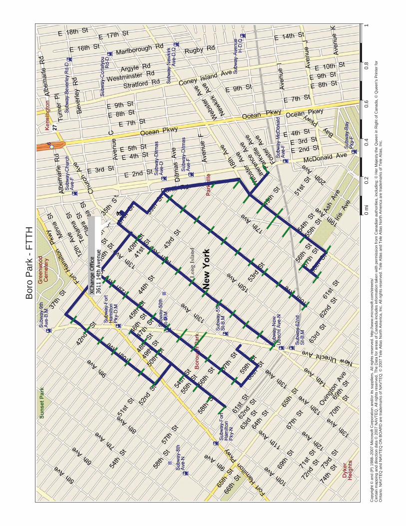
This network will be designed as an independent system consisting on customer owned conduit system and customer owned fiber optic cable network with a customer owned node facility. The node located at 3611 14th Street will support 5 distribution backbone cables and all applicable network gear. The distribution backbone cables will run southerly along the 5-Avenues to approximately 60th Street. These backbone cables will support the tie-ins of all the easement lateral cables running to each backyard easement.

Boro Park Feasibility Study Fiber –To-The -Home
2. Node Facilities
This node facility will be fully equipped with environmental systems capable of maintaining the interior environment at 72 degrees F. In addition to the primary power system, all equipment facilities will have complete battery backup for the electronics (-48V DC) as well as an emergency generator backup power system.
3. Main Backbone
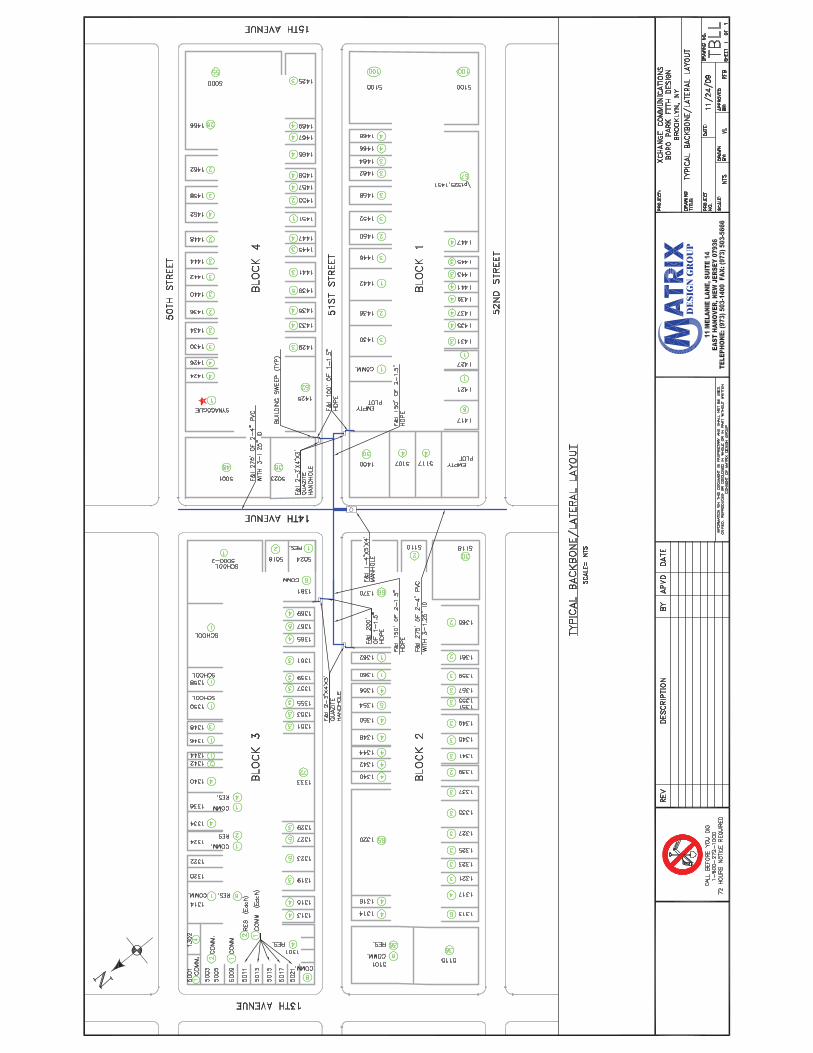
The main fiber optic backbone will consist of a 432ct FOC and will be the main trunk feed to all the backyard easement lateral feeds. The Backbone will be installed within a customer owned conduit system consisting of 2-4” pvc conduit with 3-1.25” innerduct. Manholes will be placed approx. every other street intersection.
A typical easement plan can be found in the attachment section in the back of the study
4. Easement Laterals
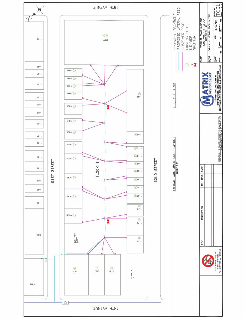
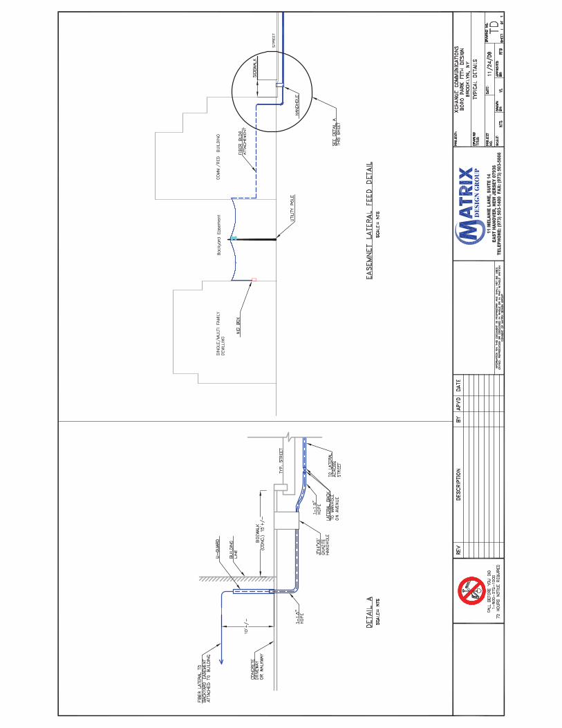
The lateral cable will consist of a 24ct FOC and will be the feeder cable to the backyard easements. The lateral feeds will be installed within 1-1.5” HDPE conduit that will tie into the backbone manhole system through a new handhole placed in the sidewalk area at the location of the entry. From the handhole we anticipate two options of connecting to the rear easements. First, trench down either a driveway or walkway to the existing pole line. Second, trench to the nearest building commercial or residential apartment build corner and sweep up the building to an approx. height of 10’ in protected conduit. Then travel along the building with the fiber using cable clamps spaced every 10’ to a point closest to the pole line in the easement. The cable will now be laced aerially to a strand wire connecting the poles (approx 9) in the easement. The lateral cable within the easement will have 2-splitters that all the customer fiber drops will be spliced into.
5. Customer Fiber Drop
The customer fiber drop will consist of a 2ct FOC that will be an aerial connection from the customer home to the nearest utility pole then travel back to one of the two lateral cable splitters. The customer drop will follow the same path that the existing telephone and cable company’s have taken. It is our recommendation that during the initial phase of construction of the backyard easement facilities, customer service drops are extended to each dwelling from the network access point (NAP), to a blank Network interface device (NID) located at each premise. Construction of customer service drop facilities during network construction helps to better utilize the construction budgets and minimizes trip charges in the future. Further, it has been proven that this type of “pre-installation” activity creates customer interest and helps to increase the buy rates for the pre-installed serving area.
A typical easement plan can be found in the attachment section in the back of the study

Boro Park Feasibility Study Fiber –To-The -Home
E. Make Ready Work (Verizon and CATV)
Because the backyard easement feed the residents with telephone and cable aerially via utilty poles, potential make ready moves would be required by the utility companies. The reason for these make ready moves is to create a separation between the cable and telephone companies facilities that would allow for the installation of Xchange Communications fiber plant.
F. Project Management and Construction Coordination
Matrix’s ability to provide a complete overall management for this project allows us to optimize the necessary control to ensure the timely completion, quality of work, and cost effectiveness of each undertaking. We approach each endeavor from the client’s point of view and develop a strategy that will meet or exceed their objectives.
Our skilled professionals will be there from design, final network acceptance, overseeing every phase of the project. Matrix will prepare weekly reports outlining the progress made during the week and to identify and remove any obstacles that may create delay’s in the project.
Matrix recognizes that the engineering, design and implementation of communications networks is a fast-track industry, therefore, stringent, project-tested management practices will be implemented to ensure all facets and components of the planning, design, and construction process have received the appropriate level of attention necessary for a successful project. Our strength comes through the integrated services we offer our clients and our commitment to their ongoing success. We create an atmosphere built around teamwork; both within our company and in the co-operative partnerships we form with our clients.
G. Subcontractors
Matrix will employ qualified subcontractors and employees for certain tasks within the project scope. Our efforts in hiring subcontractors will be based on the following: experience, number of employees, quality equipment used, references and there base location. Contractors will be hired in accordance with the appropriate union qualifications.
H. Fiber Management
The creation of an overall map to show the aerial and underground cable, splices, poles and manholes will be the corner stone of this task. The locations of the splices will be dependent on the number of lateral feeds we can provide without exhausting our conduit capacity along the main backbone route. Other activities that will help in the management process are the following:
Splice Assignment Sheets will be created to identify individual fiber usage. Route Forms will be created to identify footages of the fiber along the pole lines and manholes as well as to the splice locations. These sheets prove to be extremely important for emergency maintenance activities due to unpredictable breaks in the line. Should the fiber have a break a technician can send a light through the
Boro Park Feasibility Study Fiber –To-The -Home
line in the Node to get a footage reading and cross reference the forms to pinpoint the location, thus reducing the response time.
I. Restoration
Based on our extensive underground utility construction experience and working knowledge of a wide variety of state/county/local regulatory agencies and right-of-way owners throughout the tri-state area, Matrix recognizes the importance of maintaining and restoring all properties accessed or disturbed during construction. Upon completion of excavation work all surfaces will be restored to a condition equal or better than original condition. All restoration work will be performed in accordance with the specifications, standards and procedures set forth by the governing agency or applicable right-of-way / property owner. Matrix strives to maintain a clean and hazard free work area including daily removal of spoils, unused material and debris from the property.
J. Fiber Splicing and Testing
1. Fusion Splicing Procedures
Fiber optic splicing will be performed by the fusion splicing method. Laboratory testing and field experiences have shown that fusion splicing provides the ultimate splice-loss results with the greatest splice longevity. In addition to the performance benefits, fusion splicing allows for mass-fusion splicing of up to 12-fiber ribbons, which greatly increases splicing production and reduces splicing costs for the project.
The following is a general description of the typical procedures associated with fusion splicing:
i. Cable Preparation Fiber optic cables tails are brought inside a mobile splice lab or controlled environment, and the technician enters them into the splice closure according to the manufacturer’s specifications. The appropriate amount of slack is stored in the lower half of the closure for future use if necessary. The fiber is measured to length and routed into to the splice trays. The fiber is then cleaned and prepared for splicing.
ii. Fiber Preparation and Fusion Splicing Once the fibers are cleaned and prepared, each fiber or ribbon is cleaved and spliced to the corresponding fiber from the other tail. Care is taken to orient the fibers in a one-to-one fashion. Each fusion splice is then placed inside a splice protection sleeve and heated to adhere the sleeve to the fiber. The protected splice is then placed into the splice holder chip in ascending order. All cables and splice trays are clearly labeled to facilitate identifying fibers by number, color assignments and direction.
iii. Cable / Splice Housing Final Storage After completing all necessary splices, the technician closes the splice housing, and pressurizes the closure to 5 psi to flash test the seal. When the test is completed, the housing is de-pressurized. The cable is neatly coiled and the

Boro Park Feasibility Study Fiber –To-The -Home
splice closure is racked on the side of the hand hole or manhole and secured as required. In the case of an aerial splice location, the closure is hung on the strand, and the tails are lashed out securely.
2. Testing Procedures
This section describes the processes that will be used to complete network acceptance test on all fiber optic spans. The fiber optic path will be analyzed in several steps in order to complete a network acceptance test. All termination splices will be checked with a visible light source in order to verify the correctness of their position in the termination panel as well as color-to-color match. Next, all termination splices will be measured with a GN Nettest CMA 4000 Optical Time Domain Reflectometer (OTDR) to determine if they all meet the spec set forth by in the specifications for the given type of fiber.
Typically, non-zero dispersion shifted fiber is tested in the 1550 nm wavelength only. Single mode fiber is tested in both the 1550 and 1310 nm wavelengths. Multimode fiber is tested in both the 1300 and 850 nm wavelength. All termination splices will be measured with a launch reel of at least 1 km in length attached to the OTDR. The traces will be numbered sequentially according to the port position, named according to the test location, and stored electronically.
After verifying that all termination splices are within spec, the overall span will be tested in a similar manner. A GN Nettest CMA 4000 OTDR will be used to measure the optical length of the span as well as the loss associated with each field splice along the path. All associated fibers will be tested bi-directionally. The traces will be numbered sequentially according to the port position, named according to the test location/ end location, and stored electronically. Utilizing GNNettest emulation software, a test report will be generated listing the bi-directional splice loss associated with each fiber at each splice location along the span.
The final step in completing a network acceptance test is the end-to end power test, which verifies continuity between the end points on each fiber as well as measures power loss across the path. Exfo FOT-920 Maxtesters will be used to complete bi-directional dual wavelength power testing. Utilizing EXFO Toolbox emulation software, test results will be compiled in tabular form. All reports and electronic data will be submitted to the customer as part of the final as-built documentation package, and also stored on file for future reference.
K. Permitting and Right-of-Way Requirements
From the onset of the network design solution, the Matrix team recognizes and understands the complex maze of paperwork and regulatory processes associated with permit acquisition and jurisdictional regulations. Matrix, with its experienced construction associates, is ideally suited to provide a seamless approach to permit acquisition. Matrix is particularly adept at working and coordinating with various transportation and state/county/local regulatory bodies.

Boro Park Feasibility Study Fiber –To-The -Home
L. Traffic Control Plans
Keeping the traveling public moving safely and conveniently is a major responsibility. This is especially important in construction work zones, which, if not properly managed, can be hazardous to construction personnel and motorists. Typical accident rates are three to five times higher in work zones.
To reduce the likelihood of occurrence and to reduce the impact of incidents on motorists and construction zone personnel, we propose that a typical traffic control plan be developed and coordinated with the local uniformed police department. The Traffic Control Plans will be designed in accordance with the applicable NYDOT and MUTCD standards.
The fiber routes will travel in and out of traffic lanes and pass from the vicinity of moving vehicular and pedestrian traffic to rural less traveled paths. Special attention must be paid to areas of changing conditions as well areas of intense use and assure protection of traffic is a priority in all areas.
V. Service Installation Requirements
A. House Drop Service Work
The customer fiber drop will be run from each premise location to the nearest splitter location. The drop cable will be run consistently with the current accepted house drop applications.
B. In-House Wiring and Activation Work
With any successful network deployment, the most important and most overlooked aspect of the build is the customer interface. Several issues come into play in this area and can be summed up into three distinct areas.
As it has been determined that FTTH will be used, there are still many questions to be answered regarding how service will be delivered inside of the home. As almost all of the properties on this build are MDU’s, there may not be any single answer for how best to wire these homes.
The most desirable method for wiring service would be to install all premises with Cat5E or CAT6 wiring. This could provide for up to 1Gbps of Ethernet connectivity between telco equipment and customer premise equipment. In keeping all traffic natively Ethernet between the telco equip and the CPE there will be no additional complex modem equipment to purchase, install and support. It is our opinion that all new CAT5e / CAT6 wiring should be installed in each building unless it is physically impossible to do so. While the initial labor costs to do so could be high upfront, in the long term new inside wire will be the most cost effective and best performing solution.
In the cases where there are buildings that cannot be rewired, there are two solutions that could be employed to reuse existing wiring.
Boro Park Feasibility Study Fiber –To-The -Home
1. HPNAv3 (Home Phone Networking Alliance) – This technology delivers broadband over existing inside telephone wiring or existing coaxial cable. It requires the installation of “HPNA modems” for each location. For Boro Park, it is assumed that coaxial cable may not be available in many units. While HPNA v3.0 is capable of delivered speeds of up to 128Mbps, this will only occur if the condition of the existing telephone wiring is optimal. This product is often marketed as “simply plug it in and it works”. The truth is that in large, older buildings where the condition of the inside phone wire is unknown, there could be a significant amount of labor and retrofit work to get HPNA to work optimally. As mentioned above, if there is no possibility of running new cabling inside these buildings, HPNA is an acceptable alternative – but will almost certainly require some significant effort in retrofitting the existing wires.
2. VDSL – While most people think of DSL as a broadband technology that is used “outside” of a premise, it is also very useful in delivering broadband “inside” of large MDU buildings where rewiring is impossible. The concept behind VDSL for “inside wiring” is to bring a large broadband pipe into the phone/wiring closet of a large MDU – then install a VSDL DSLAM and use existing inside phone wire to deliver broadband to a VDSL modem in each unit. As with HPNA technology mentioned above, VDSL will work very well when the condition of the inside wiring is optimal. It is highly likely that in order to have VDSL work properly, a significant amount of labor will be required to retrofit existing phone wiring.
VI. Staffing Considerations
For the financial analysis of the proposed project, a mean average of one employee for 1000 subscribers was used. At various times during the project, that number may increase or decrease.A summary of the recommended technical staffing levels follows below. The numbers and types of employees may need to be adjusted to suit varying needs of the project.
- Outside Plant Technicians: During the construction phase of the project and early on after service starts to be offered, the number of outside plant staff required will be higher than in later years. Once the network has matured a group of 3 outside plant employees can handle the volume of day to day activity (patching, splicing, drop wire work). During the early years, when there potentially could be a lot of contract labor doing installation and construction work, these 3 OSP techs will primarily function as quality control. In addition, these techs should be cross trained to function as repairs techs for inside and outside troubles.
- Repair Techs: As mentioned above, due to the initial high volume of installations, contracted labor would probably be used for customer installation work. However, it is essential that any repair techs are actual employees. In my experience, having contract labor perform repair work (especially on a new install) is counterproductive. Having an in house repair tech(s) will assist with flushing out faulty contractor installation work. In addition, in house repair will usually fix the trouble on the 1st truck roll. If a good quality control system is put in place during installations, the number of service

Boro Park Feasibility Study Fiber –To-The -Home
tech staff needed will be far less. 1 fulltime repair tech per 4000 customers is sufficient. When the trouble volume occasionally spikes, outside plant techs should be cross trained to do repair work.
- Installers: After the initial flood of installation work in the early years drops off, it will no longer be necessary to maintain a contracted installation force. I would recommend in house installers be used. In the absolute worst case scenario, an installer should be able to do 2 installs per day (assuming high labor wiring). In any case, a minimum of 2 installers should be employed. Additionally, repair staff and outside plant staff may be used during peak times to augment the installations team.
- Inside Plant: This would include all systems technicians. For a 2 play service offering of phone and internet, a crew of 3 engineers/techs should easily be able to effectively maintain the network equipment. This number is needed on day 1 and should remain the same regardless of the number of customers. It is essential that all systems staff are competent to manage all of the equipment. You do not want a scenario where 1 employee is the Class 5 switch person, and another one is the router person, and a third person is the access equipment (GPON) tech . Having 3 fully cross trained employees will provide ample coverage for daily operations and after hour on call coverage.
- Customer Technical Support (Help Desk) – Having the right number of staff for technical support can be tricky as there are often peaks and lows. You can never have enough staff when there is a peak (like during a network outage), but the goal is to provide enough coverage that during normal operating conditions, customers can get support without waiting more than a few minutes. You may also find that early on in the network build as a flood of new customers are installed the help desk load could be very high. The reason for this almost always customer education. New customers tend to call in more frequently. It is my recommendation that technical support be available 8am – 10pm x 7 days a week. To effectively achieve this coverage, you would need a minimum of 4 full-time help desk staff regardless of call volume. It is difficult to determine if more than 4 would be needed because of the number of variables. What I can say is that if the installation work is of a high quality and there are few repair calls, 4 employees could handle a customer base of 10000.
- Customer Service (new service, change service, collections): As with the help desk, customer service will need a baseline level of staff regardless of the number of customers. The customer service group does not typically cover as many hours as technical support. Typically they would work from 8am – 8pm x 6 days a week. To achieve this, a staff of 3 CS reps would be needed. Also, as with help desk, it is difficult to determine the exact number of staff needed. Under no circumstances should more than 6 be needed to support a network of 10000 users. If it is possible, CS and HD employees should be cross trained to serve in both capacities. This could assist in keeping the number of employees needed to maintain operations low.

Boro Park Feasibility Study Fiber –To-The -Home
VII. Upstream Broadband Link Considerations
In order to provide broadband internet services over FTTH the telco must purchase a large amount of access from 1 or more IP transit providers. How much bandwidth to purchase is dependent upon a few factors:
1. How much access will you be selling to your customers? 1Mbps , 10Mbps, 50Mbps? A mix of offerings? For the sake of this engineering estimate, we will assume all customers will be provisioned for 10Mbps of access.
2. What will the oversubscription ratio be? For broadband services, a ratio of 20:1 is considered excellent. Oversubscription ratios of 40:1 or higher will most likely have your customers complaining of slow speeds. For this discussion, we will assume a 25:1 oversubscription ratio.
If the telco has 10,000 subscribers each receiving 10Mbps access, the telco would need to purchase 4Gbps worth of access to maintain a 25:1 ratio. Assuming the telco can gain access to a carrier neutral telecom “hotel”, the telco could most likely buy IP transit access at $10 per Mb or less. That translates to $40,000 per month for 4Gbps. If the telco cannot get access to a carrier hotel or construct to one, the cost per MB will increase as they will have to buy local loops to deliver the transit.
As mentioned above, the telco may buy transit from 1 or more transit provider. Buying access from more than 1 provider will give the benefit of service redundancy and increased route performance. While it is not absolutely necessary have more than 1 transit provider it is highly recommended.
It is also highly recommended that the telco secure an IP address allocation from ARIN. This will allow the telco to easily switch transit providers without having to readdress all of their equipment. To receive an IP allocation, a standard justification for will need to be filled out. If the telco has 10,000 subscribers, it will need at least 10,000 IP addresses. ARIN’s current fees for this size allocation are ~$4500 per year.
Lastly, the telco must have a router to handle the IP traffic. There are many manufacturers who make routers to handle this quantity of traffic. Costs can range and vary greatly from $10k to $100k and beyond.

Boro Park Feasibility Study Fiber –To-The -Home
VIII. Business Plan Financial Analysis

XCha
nge
Tele
com
B
usin
ess
Plan
Fin
anci
al A
naly
sis
Sum
mar
yY
R 1
YR
2Y
R 3
YR
4Y
R 5
YR
6Y
R 7
YR
8Y
R 9
YR
10
CA
PEX
36,8
70,6
369,
550,
006
11,1
24,0
179,
491,
591
2,47
6,95
964
9,43
165
0,59
865
1,82
990
3,96
168
5,38
068
6,86
3
Rev
enu e
173,
055,
833
2,06
1,30
14,
055,
623
14,7
29,3
5718
,536
,991
19,7
21,0
3620
,670
,537
21,6
50,1
4422
,715
,580
23,8
64,6
5025
,050
,612
Ope
ratin
g Ex
pens
e(7
0,83
3,27
1)(1
,625
,592
)(2
,028
,608
)(4
,683
,228
)(6
,316
,349
)(7
,706
,572
)(8
,288
,437
)(8
,927
,380
)(9
,623
,009
)(1
0,39
2,12
8)(1
1,24
1,96
9)
Ope
ratin
g Pr
ofit
102,
222,
562
435,
710
2,02
7,01
510
,046
,130
12,2
20,6
4212
,014
,464
12,3
82,1
0112
,722
,765
13,0
92,5
7113
,472
,522
13,8
08,6
43
Oth
er C
ash
Out
31,3
89,2
91(2
,183
,897
)(2
,406
,789
)(2
,648
,863
)(2
,974
,710
)(3
,291
,288
)(3
,634
,472
)(4
,004
,342
)(4
,405
,386
)(4
,503
,226
)(4
,601
,278
)
Free
Cas
h Fl
ow67
,568
,311
(1,7
48,1
87)
(379
,774
)7,
397,
266
9,24
5,93
28,
723,
176
8,74
7,62
88,
718,
423
8,68
7,18
58,
969,
296
9,20
7,36
5
Ass
umpt
ion s
Res
ourc
es R
equi
red
24,8
96,3
09$
Su
m to
be
Bor
row
ed15
,000
,000
$
Equi
ty10
,000
,000
$
Num
ber o
f Hom
es/B
usin
esse
s Pa
ssed
12,8
0029
,150
43,0
5045
,100
45,1
0045
,100
45,1
0045
,100
45,1
0045
,100
Tota
l Cus
tom
ers
3,10
27,
996
12,2
3913
,243
13,6
7414
,104
14,5
3514
,986
15,4
3715
,888
Ave
rage
Pen
etra
tion
Rat
es24
.2%
27.4
%28
.4%
29.4
%30
.3%
31.3
%32
.2%
33.2
%34
.2%
35.2
%
Inte
rnal
Rat
e of
Ret
urn
on In
vest
men
t27
%
Inte
rnal
Rat
e of
Ret
urn
on E
quit y
44%
Com
pany
Ter
min
al V
alue
at t
he e
nd o
f 10
yea
rs (8
x Fr
ee C
ash
flow
) 78
,310
,035
$

XCha
nge
Tele
com
B
usin
ess
Plan
Fin
anci
al S
umm
ary
Det
ail
Sum
mar
yY
R 1
YR
2Y
R 3
YR
4Y
R 5
YR
6Y
R 7
YR
8Y
R 9
YR
10
YR
11
Out
side
Pla
nt C
onst
ruct
ion
Act
iviti
e sH
eade
nd R
enov
atio
ns65
0,00
0$6
50,0
00ProjectM
anagem
ent&
Engine
ering
1,50
0,00
045
0000
5250
0045
0000
7500
0Ba
ckbo
neUnd
ergrou
ndCo
nstructio
n6,60
0,00
019
8000
023
1000
019
8000
033
0000
Easemen
tDistributionCo
nstructio
n3,52
0,00
010
5600
012
3200
010
5600
017
6000
DropInstallatio
nto
allhom
es3,52
0,00
010
5600
012
3200
010
5600
017
6000
Und
ergrou
ndFibe
rInstallatio
n25
0,00
075
000
8750
075
000
1250
0Fibe
rSplicing
300,00
090
000
1050
0090
000
1500
0Fibe
rTesting
300,00
090
000
1050
0090
000
1500
0Pe
rmitting
100,00
030
000
3500
030
000
5000
Fibe
rCable
158,40
047
520
5544
047
520
7920
Std
dH
d15
840
4752
5544
4752
792
Strand
andHardw
are
15,840
4752
5544
4752
792
Splitters,N
IDho
usings
andMisc
500,00
015
0000
1750
0015
0000
2500
0Term
inationshelvesrackingetc
500,00
015
0000
1750
0015
0000
2500
0P
ole
mak
e re
ady
$198
,000
$99,
000
$99,
000
$0$0
Tool
s an
d m
isc.
$145
,000
$100
,000
$5,0
00$5
,000
$5,0
00$5
,000
$5,0
00$5
,000
$5,0
00$5
,000
$5,0
00O
SS
sof
twar
e$1
00,0
00$1
00,0
00$0
$0$0
$0$0
$0$0
$0$0
Faci
litie
s M
gt s
oftw
are
$110
,000
$50,
000
$40,
000
$20,
000
$0$0
$0$0
$0$0
$0V
ehic
les
$100
,000
$40,
000
$20,
000
$20,
000
$20,
000
$0$0
$0$0
$0$0
sub
tota
l$1
8,56
7,24
0$6
,218
,272
$6,2
06,4
84$5
,224
,272
$888
,212
$5,0
00$5
,000
$5,0
00$5
,000
$5,0
00$5
,000
C
ontin
genc
y $1
,876
,724
$621
,827
$620
,648
$522
,427
$88,
821
$500
$500
$500
$20,
500
$500
$500
Tota
l Non
Var
iabl
e C
apex
$20,
443,
964
$6,8
40,0
99$6
,827
,132
$5,7
46,6
99$9
77,0
33$5
,500
$5,5
00$5
,500
$25,
500
$5,5
00$5
,500
Varia
ble
CA
PEX
Ass
umpt
ions
Insi
de W
iring
/HP
NA
Con
verte
r40
0O
LT12
0O
NU
160
UP
S10
0C
usto
mer
Dro
p In
stal
l (Y
rs 4
-10)
345
New
Sub
scrib
ers
3,10
24,
894
4,24
31,
005
431
431
431
451
451
451
Tota
l Sub
scrib
ers
YE
3,10
27,
996
12,2
3913
,243
13,6
7414
,104
14,5
3514
,986
15,4
3715
,888
Varia
ble
CA
PEX
Cos
t per
Cus
tom
er78
078
478
813
3313
3613
3813
4013
4313
4613
49
Tota
l Var
iabl
e C
AP
EX
Cos
t14
4881
0024
1956
038
3650
433
4365
413
3922
057
4938
5759
8157
7079
6057
6860
7035
6083
60V
aria
ble
CA
PE
X C
ontin
genc
y17
3857
2$2
90,3
47$4
60,3
80$4
01,2
38$1
60,7
06$6
8,99
3$6
9,11
8$6
9,25
0$7
2,69
2$7
2,84
4$7
3,00
3
Tota
l Var
iabl
e C
APE
X16
2266
7227
0990
7.2
4296
884
3744
892
1499
926
6439
3164
5098
6463
2967
8461
6798
8068
1363
Sub
Tota
l CA
PEX
3005
6116
8637
832
1004
2988
8567
926
2227
432
5799
3858
0981
5820
7981
0768
6120
3561
3360
Sub
Tota
l CA
PEX
Con
tinge
ncy
9121
7410
8102
992
3666
2495
2869
493
6961
869
750
9319
273
344
7350
3To
tal C
APE
X36
8706
36$9
,550
,006
$11,
124,
017
$9,4
91,5
91$2
,476
,959
$649
,431
$650
,598
$651
,829
$903
,961
$685
,380
$686
,863
cum
ulat
ed C
apE x
$9,5
50,0
06$2
0,67
4,02
3$3
0,16
5,61
5$3
2,64
2,57
4$3
3,29
2,00
5$3
3,94
2,60
3$3
4,59
4,43
2$3
5,49
8,39
2$3
6,18
3,77
2$3
6,87
0,63
6

XCha
nge
Tele
com
B
usin
ess
Plan
Fin
anci
al S
umm
ary
Det
ail
REV
ENU
E A
SSU
MPT
ION
S:U
RB
AN
Res
iden
tial H
H p
asse
d: y
r end
to
41,0
0012
,300
26,6
5038
,950
41,0
0041
,000
41,0
0041
,000
41,0
0041
,000
41,0
00 B
usin
esse
s pa
ssed
: yr e
nd
to41
0050
02,
500
4,10
04,
100
4,10
04,
100
4,10
04,
100
4,10
04,
100
Tak
e ra
te, e
nd o
f yea
r: R
ES
24%
27%
28%
29%
30%
31%
32%
33%
34%
35%
n
umbe
r of s
ubs
end
of y
ear:
res
2,95
27,
196
10,9
0611
,890
12,3
0012
,710
13,1
2013
,530
13,9
4014
,350
n
umbe
r of n
ew s
ubs
durin
g yr
: re
s2,
952
4,24
43,
711
984
410
410
410
410
410
410
n
umbe
r of s
ubs:
ave
rage
for y
r: re
s1,
476
2,12
29,
051
11,3
9812
,095
12,5
0512
,915
13,3
2513
,735
14,1
45
Tak
e ra
te, e
nd o
f yea
r: B
US
30.0
%32
.0%
32.5
%33
.0%
33.5
%34
.0%
34.5
%35
.5%
36.5
%37
.5%
n
umbe
r of s
ubs,
end
of y
ear,
bus
150
800
1,33
31,
353
1,37
41,
394
1,41
51,
456
1,49
71,
538
n
umbe
r of n
ew s
ubs
durin
g ye
ar:
bus
150
650
533
2121
2121
4141
41
num
ber o
f sub
s, a
vera
ge fo
r yr:
bus
7532
51,
066
1,34
31,
363
1,38
41,
404
1,43
51,
476
1,51
7
Ave
rev/
mo/
res.
sub
(all
serv
ices
)$8
3.97
$85.
65$8
7.36
$89.
11$9
0.89
$92.
71$9
4.56
$96.
46$9
8.38
$100
.35
Ave
rev/
mo/
bus.
sub
(all
serv
ices
)$3
66.8
0$3
74.1
4$3
81.6
2$3
89.2
5$3
97.0
4$4
04.9
8$4
13.0
8$4
21.3
4$4
29.7
7$4
38.3
6R
EVEN
UE
ESTI
MA
TES
re
side
ntia
l$1
,487
,280
$2,1
80,7
25$9
,488
,364
$12,
188,
089
$13,
192,
071
$13,
912,
045
$14,
655,
542
$15,
423,
213
$16,
215,
729
$17,
033,
776
bu
sine
ss$3
30,1
21$1
,459
,136
$4,8
82,8
31$6
,272
,028
$6,4
95,1
39$6
,724
,667
$6,9
60,7
77$7
,255
,467
$7,6
12,0
22$7
,979
,936
in
stal
l't'n
cha
rge
reve
nue
disc
ount
for w
a0.
25$2
43,9
00$4
15,7
63$3
58,1
63$7
6,87
5$3
3,82
5$3
3,82
5$3
3,82
5$3
6,90
0$3
6,90
0$3
6,90
0
TOTA
L R
EVEN
UE S
$2,0
61,3
01$4
,055
,623
$14,
729,
357
$18,
536,
991
$19,
721,
036
$20,
670,
537
$21,
650,
144
$22,
715,
580
$23,
864,
650
$25,
050,
612
Uni
t Cos
t of G
oods
Sol
d
Res
iden
tial
14.2
514
.30
14.3
514
.40
14.4
514
.50
14.5
514
.61
14.6
614
.71
Com
mer
cial
21.2
521
.25
21.2
521
.25
21.2
521
.25
21.2
521
.25
21.2
521
.25
OPE
RA
TIN
G E
XPEN
S EC
tfG
dS
ld25
2396
3640
9215
5856
619
6967
720
9749
121
7624
722
5554
423
3538
724
1577
824
9672
4C
ost o
f Goo
ds S
old:
re
s.25
2396
3640
9215
5856
619
6967
720
9749
121
7624
722
5554
423
3538
724
1577
824
9672
4bu
s:19
125
8287
527
1894
3424
0134
7629
3528
5635
8084
3659
2537
6380
3868
35
pol
e at
tach
men
t fee
s,
049
5099
0099
0099
0099
0099
0099
0099
0099
00
Out
side
Pla
nt e
mer
genc
y re
pair
cont
ract
3000
1200
012
000
1200
012
000
1200
012
000
1200
012
000
1200
0
Pro
fess
iona
l Ser
vice
s
2500
025
000
5000
5000
5000
5000
5000
5000
5000
5000
P
arts
& m
ater
iels
010
3370
1508
2816
3213
1664
6016
9713
1729
7217
7492
1809
1918
4353
P
ower
/hea
t/fue
l etc
.12
0048
0049
4450
9252
4554
0255
6557
3159
0360
21
veh
icle
s 14
000
2142
029
131
3714
237
885
3864
339
416
4020
441
008
4182
8
Wag
es &
Sal
arie
s83
0000
8443
5017
7066
827
1152
238
1047
442
3520
647
1029
552
3152
158
1623
364
7245
5
Ren
t75
000
7500
075
000
7500
075
000
7650
078
030
7959
181
182
8280
6
Pro
perty
Insu
ranc
e11
0022
0023
1024
2625
4726
7428
0829
4830
9632
50
Lia
bilit
y In
sura
nce
600
1200
1212
1224
1236
1249
1261
1274
1287
1299
F
AP
s gr
ound
rent
@ $
5K p
er u
nit
020
000
2500
030
000
3000
030
000
3000
030
000
3000
030
000
in
sura
nce,
on
Hub
and
oth
er re
leva
nt p
rope
rty50
000
5000
050
000
5000
050
000
5000
050
000
5000
050
000
5000
0
dire
ctor
s &
Offi
cers
insu
ranc
e15
0000
1500
0015
0000
1500
0015
0000
1500
0015
0000
1500
0015
0000
1500
00M
isce
llane
ous
2500
035
000
4500
050
000
5000
050
000
5000
050
000
5000
050
000
Mis
cella
neou
s25
000
3500
045
000
5000
050
000
5000
050
000
5000
050
000
5000
0
Mar
ketin
g50
0015
000
2000
025
000
3000
035
000
4000
045
000
5000
055
000
O
pera
ting
Exp
ense
Con
tinge
ncy
1741
7121
7351
5017
7467
6752
8257
0488
8047
9565
0510
3103
711
1344
212
0449
7TO
TAL
Ope
ratin
g Ex
pens
e22
3603
4916
2559
220
2860
846
8322
863
1634
977
0657
282
8843
789
2738
096
2300
910
3921
2811
2419
69

XCha
nge
Tele
com
B
usin
ess
Plan
Fin
anci
al S
umm
ary
Det
ail
EB
ITD
A (
= op
erat
ing
prof
it)$3
6,74
3,96
0$4
35,7
10$2
,027
,015
$10,
046,
130
$12,
220,
642
$12,
014,
464
$12,
382,
101
$12,
722,
765
$13,
092,
571
$13,
472,
522
$13,
808,
643
deb
t ser
vice
ratio
0.20
0.
93
4.60
5.
60
5.50
5.67
5.83
6.00
6.17
6.32
$0$0
$0$0
$0$0
$0$0
$0$0
Fina
ncin
g re
quire
men
t for
Pro
ject
itse
lf($
9,11
4,29
6)($
9,09
7,00
2)$5
54,5
38$9
,743
,682
$11,
365,
033
$11,
731,
502
$12,
070,
936
$12,
188,
611
$12,
787,
143
$13,
121,
779
C
umul
ated
($9,
114,
296)
($18
,211
,298
)($
17,6
56,7
60)
($7,
913,
078)
$3,4
51,9
56$1
5,18
3,45
8$2
7,25
4,39
4$3
9,44
3,00
5$5
2,23
0,14
7$6
5,35
1,92
7O
THE
R C
AS
H O
UT
d
ebt s
ervi
ce (i
nter
est+
prin
cipa
l)$2
,183
,897
$2,1
83,8
97$2
,183
,897
$2,1
83,8
97$2
,183
,897
$2,1
83,8
97$2
,183
,897
$2,1
83,8
97$2
,183
,897
$2,1
83,8
97
Pro
perty
Tax
**$9
5,50
0$2
06,7
40$3
01,6
56$3
26,4
26$3
32,9
20$3
39,4
26$3
45,9
44$3
54,9
84$3
61,8
38$3
68,7
06
Allo
wan
ce fo
r equ
ip re
plac
emen
t (av
e 7
yr li
fe)
222,
892
$
464,
967
$
790,
813
$
1,
107,
391
$
1,
450,
575
$
1,
820,
445
$
2,
221,
490
$
2,
319,
330
$
2,
417,
382
$
tot
al($
2,18
3,89
7)($
2,40
6,78
9)($
2,64
8,86
3)($
2,97
4,71
0)($
3,29
1,28
8)($
3,63
4,47
2)($
4,00
4,34
2)($
4,40
5,38
6)($
4,50
3,22
6)($
4,60
1,27
8)
FRE
E C
AS
H F
LOW
(= "p
rofit
")($
11,2
98,1
93)
($11
,503
,790
)($
2,09
4,32
5)$6
,768
,973
$8,0
73,7
46$8
,097
,030
$8,3
90,4
75$8
,455
,680
$9,2
36,9
40$9
,788
,754
TO
TAL
AN
NU
AL
FIN
AN
CIN
G R
EQ
UIR
EM
EN
T$1
1,29
8,19
3$1
1,50
3,79
0$2
,094
,325
($6,
768,
973)
($8,
073,
746)
($8,
097,
030)
($8,
390,
475)
($8,
455,
680)
($9,
236,
940)
($9,
788,
754)
c
umul
ativ
e fin
anci
ng re
quire
men
t$1
1,29
8,19
3$2
2,80
1,98
4$2
4,89
6,30
9$1
8,12
7,33
6$1
0,05
3,59
0$1
,956
,560
($6,
433,
915)
($14
,889
,595
)($
24,1
26,5
35)
($33
,915
,290
)
Res
ourc
es re
quire
d:$2
4,89
6,30
9S
um to
be
borr
owed
$15,
000,
000
Equ
ity$1
0,00
0,00
0To
tal R
esou
rces
$2
5,00
0,00
0
Com
pany
Term
inal
Val
ue
at th
e en
d of
10
(10X
IRR
ON
INV
ES
TME
NT
10 y
ears
(10X
Fr
ee C
ash
Flow
)
(ca
sh fl
ows+
FIN
AL
VA
LUE
less
out
stan
ding
de
bt):
27%
($11
,298
,193
)($
11,5
03,7
90)
($2,
094,
325)
$6,7
68,9
73$8
,073
,746
$8,0
97,0
30$8
,390
,475
$8,4
55,6
80$9
,236
,940
$9,7
88,7
54$7
8,31
0,03
5
IRR
on
Equ
ity44
%($
9,89
6,30
9)$0
$0$6
,768
,973
$8,0
73,7
46$8
,097
,030
$8,3
90,4
75$8
,455
,680
$9,2
36,9
40$9
,788
,754
$78,
310,
035
Com
pany
Ter
min
al V
alue
at t
he e
nd o
f 10
year
s$7
8,31
0,03
5
** P
rope
rty T
ax w
as c
alcu
late
d at
1%
of C
umul
ated
CA
PE
X fo
r bud
getin
g pu
rpos
es. M
ore
deta
iled
anal
ysis
will
hav
e to
be
perfo
rmed
to a
sses
s ac
cura
te p
erce
ntag
es.

Boro Park Feasibility Study Fiber –To-The -Home
IX. Appendices
A. Overall Network Map
B. Typical Backbone/Lateral Layout
C. Typical Customer Drop Layout
D. Typical Details
E. Equipment Specifications
Cop
yrig
ht ©
and
(P) 1
988–
2007
Mic
roso
ft C
orpo
ratio
n an
d/or
its
supp
liers
. All
right
s re
serv
ed. h
ttp://
ww
w.m
icro
soft.
com
/stre
ets/
Cer
tain
map
ping
and
dire
ctio
n da
ta ©
200
7 N
AVTE
Q. A
ll rig
hts
rese
rved
. The
Dat
a fo
r are
as o
f Can
ada
incl
udes
info
rmat
ion
take
n w
ith p
erm
issi
on fr
om C
anad
ian
auth
oriti
es, i
nclu
ding
: © H
er M
ajes
ty th
e Q
ueen
in R
ight
of C
anad
a, ©
Que
en's
Prin
ter f
or
Ont
ario
. NAV
TEQ
and
NAV
TEQ
ON
BO
ARD
are
trad
emar
ks o
f NAV
TEQ
. © 2
007
Tele
Atla
s N
orth
Am
eric
a, In
c. A
ll rig
hts
rese
rved
. Tel
e At
las
and
Tele
Atla
s N
orth
Am
eric
a ar
e tra
dem
arks
of T
ele
Atla
s, In
c.
Bor
o P
ark
- FTT
H
0 m
i0.
20.
40.
60.
81
Cal
ix P
-Ser
ies
Pro
duct
Por
tfolio
Rev
05 A
ugus
t 200
9
2
700G
X SF
U O
NTs
Cal
ix 7
00G
X O
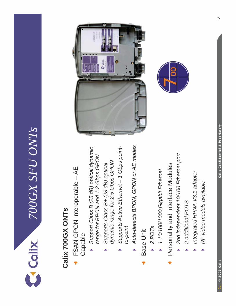
NTs
FSA
N G
PO
N In
tero
pera
ble
–A
E
Cap
able
Sup
port
Cla
ss B
(25
dB) o
ptic
al d
ynam
ic
rang
e fo
r BP
ON
and
1.2
Gbp
s G
PO
NS
uppo
rts C
lass
B+
(28
dB) o
ptic
al
dyna
mic
rang
e fo
r 2.5
Gbp
s G
PO
NS
uppo
rts A
ctiv
e E
ther
net –
1 G
bps
poin
t-to
-poi
nt
Aut
o-de
tect
s B
PO
N, G
PO
N o
r AE
mod
es
Bas
e U
nit
2 P
OTs
1 10
/100
/100
0 G
igab
it E
ther
net
Per
sona
lity
and
Inte
rface
Mod
ules
2nd
inde
pend
ent 1
0/10
0 E
ther
net p
ort
2 ad
ditio
nal P
OTS
Inte
grat
ed H
PN
A V
3.1
adap
ter
RF
vide
o m
odel
s av
aila
ble
3
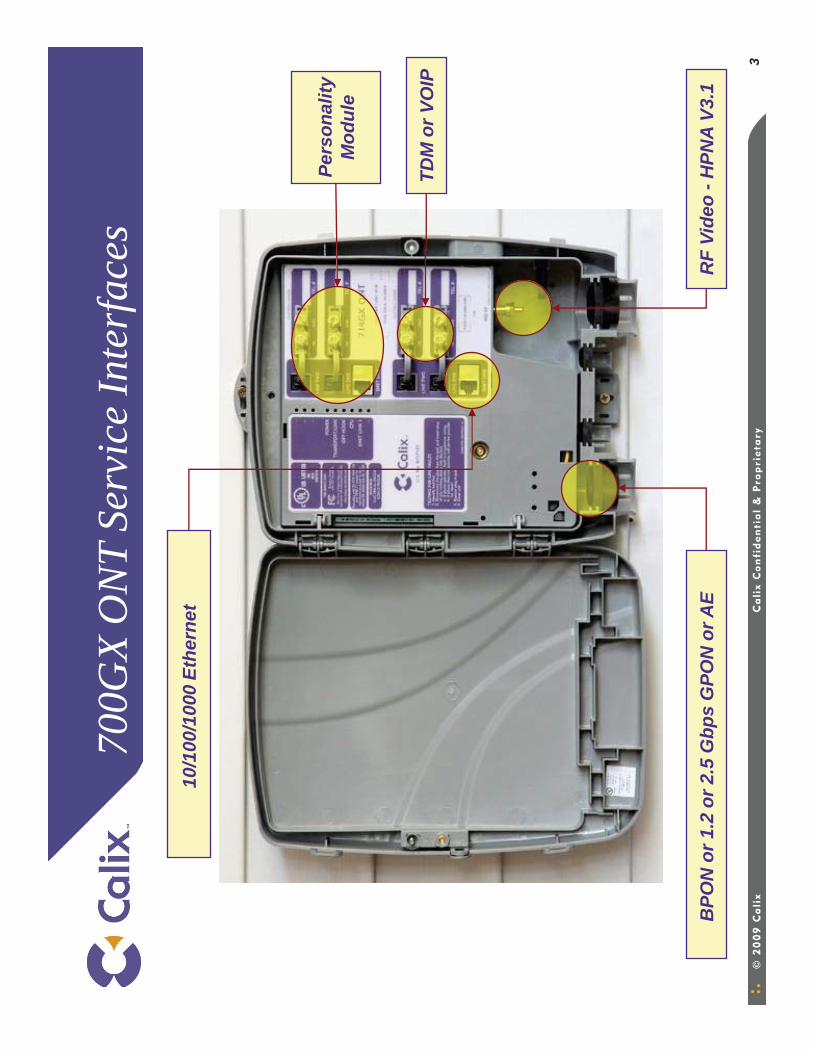
700G
X O
NT
Serv
ice
Inte
rfac
es
BPO
N o
r 1.2
or 2
.5 G
bps
GPO
N o
r AE
RF
Vide
o -H
PNA
V3.1
TDM
or V
OIP
Pers
onal
ityM
odul
e
10/1
00/1
000
Ethe
rnet
4
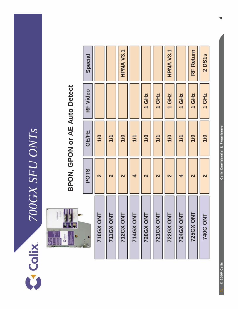
700G
X SF
U O
NTs
BPO
N, G
PON
or A
E Au
to D
etec
t
Spec
ial
1 G
Hz
710G
X O
NT
711G
X O
NT
712G
X O
NT
714G
X O
NT
720G
X O
NT
721G
X O
NT
722G
X O
NT
724G
X O
NT
725G
X O
NT
POTS
GE/
FER
F Vi
deo
21/
0
21/
1
21/
0H
PNA
V3.1
41/
1
21/
01
GH
z
21/
11
GH
z
21/
01
GH
zH
PNA
V3.1
41/
11
GH
z
21/
0R
F R
etur
n
740G
ON
T2
1/0
1 G
Hz
2 D
S1s
5
700G
X SF
U O
NT
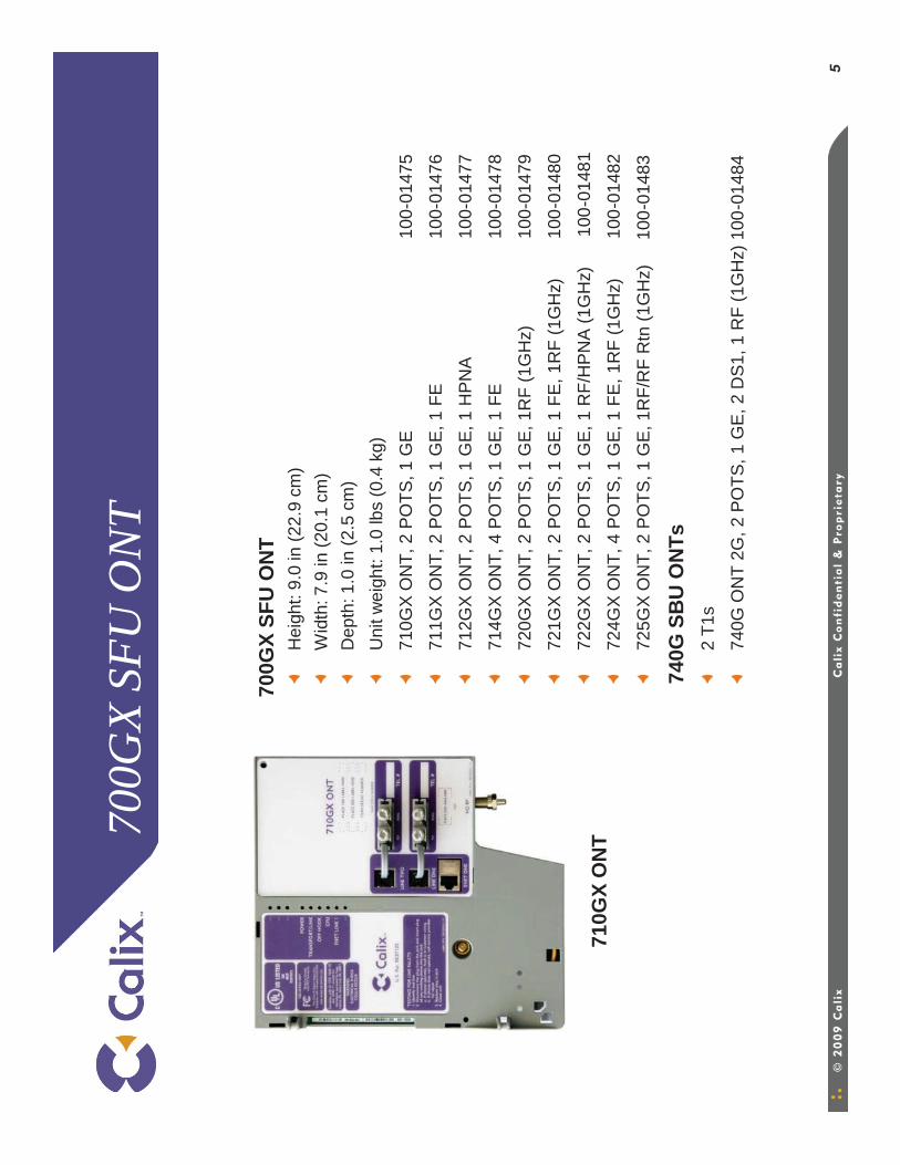
700G
X SF
U O
NT
Hei
ght:
9.0
in (2
2.9
cm)
Wid
th: 7
.9 in
(20.
1 cm
)D
epth
: 1.0
in (2
.5 c
m)
Uni
t wei
ght:
1.0
lbs
(0.4
kg)
710G
X O
NT,
2 P
OTS
, 1 G
E10
0-01
475
711G
X O
NT,
2 P
OTS
, 1 G
E, 1
FE
100-
0147
6
712G
X O
NT,
2 P
OTS
, 1 G
E, 1
HP
NA
100-
0147
7
714G
X O
NT,
4 P
OTS
, 1 G
E, 1
FE
100-
0147
8
720G
X O
NT,
2 P
OTS
, 1 G
E, 1
RF
(1G
Hz)
100-
0147
9
721G
X O
NT,
2 P
OTS
, 1 G
E, 1
FE
, 1R
F (1
GH
z)
1
00-0
1480
722G
X O
NT,
2 P
OTS
, 1 G
E, 1
RF/
HP
NA
(1G
Hz)
100-
0148
1
724G
X O
NT,
4 P
OTS
, 1 G
E, 1
FE
, 1R
F (1
GH
z)
1
00-0
1482
725G
X O
NT,
2 P
OTS
, 1 G
E, 1
RF/
RF
Rtn
(1G
Hz)
1
00-0
1483
740G
SB
U O
NTs
2 T1
s
740G
ON
T 2G
, 2 P
OTS
, 1 G
E, 2
DS
1, 1
RF
(1G
Hz)
100
-014
84
710G
X O
NT
6
700
ON
T M
ount
ing
Opt
ions
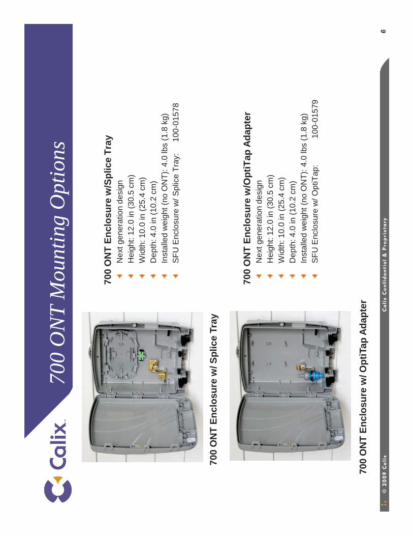
700
ON
T En
clos
ure
w/S
plic
e Tr
ayN
ext g
ener
atio
n de
sign
Hei
ght:
12.0
in (3
0.5
cm)
Wid
th: 1
0.0
in (2
5.4
cm)
Dep
th: 4
.0 in
(10.
2 cm
)In
stal
led
wei
ght (
no O
NT)
: 4.0
lbs
(1.8
kg)
SFU
Enc
losu
re w
/ Spl
ice
Tray
:
100-
0157
8
700
ON
T En
clos
ure
w/O
ptiT
ap A
dapt
erN
ext g
ener
atio
n de
sign
Hei
ght:
12.0
in (3
0.5
cm)
Wid
th: 1
0.0
in (2
5.4
cm)
Dep
th: 4
.0 in
(10.
2 cm
)In
stal
led
wei
ght (
no O
NT)
: 4.0
lbs
(1.8
kg)
SFU
Enc
losu
re w
/ Opt
iTap
:10
0-01
579
700
ON
T En
clos
ure
w/ S
plic
e Tr
ay
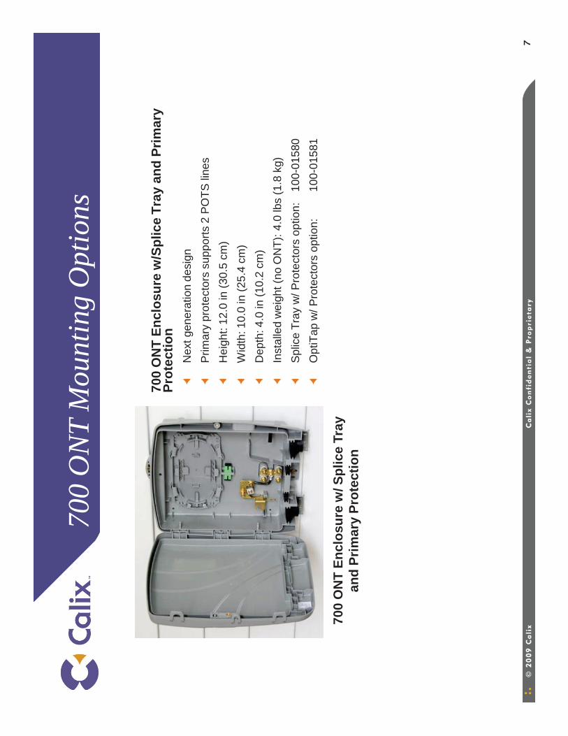
700
ON
T En
clos
ure
w/ O
ptiT
ap A
dapt
er
7
700
ON
T M
ount
ing
Opt
ions
700
ON
T En
clos
ure
w/S
plic
e Tr
ay a
nd P
rimar
y Pr
otec
tion
Nex
t gen
erat
ion
desi
gnP
rimar
y pr
otec
tors
sup
ports
2 P
OTS
line
sH
eigh
t: 12
.0 in
(30.
5 cm
)W
idth
: 10.
0 in
(25.
4 cm
)D
epth
: 4.0
in (1
0.2
cm)
Inst
alle
d w
eigh
t (no
ON
T): 4
.0 lb
s (1
.8 k
g)S
plic
e Tr
ay w
/ Pro
tect
ors
optio
n:
100-
0158
0O
ptiT
ap w
/ Pro
tect
ors
optio
n:
100-
0158
1
700
ON
T En
clos
ure
w/ S
plic
e Tr
ay
and
Prim
ary
Prot
ectio
n
8
700
ON
T M
ount
ing
Opt
ions
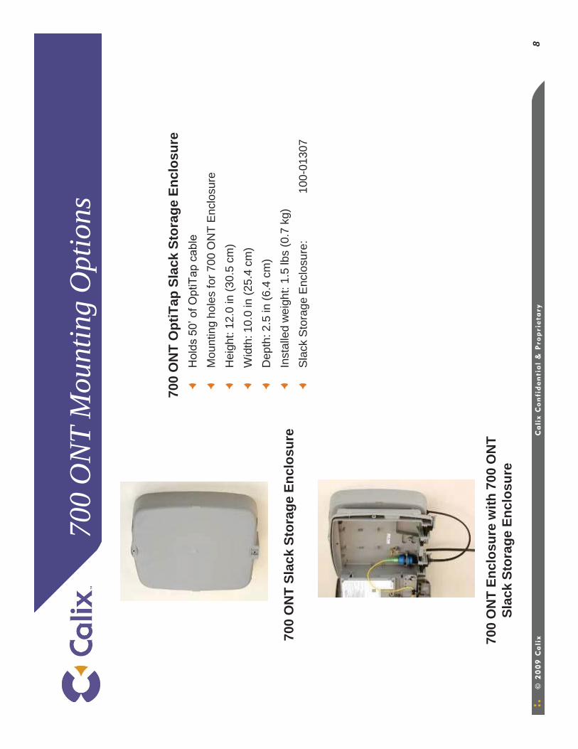
700
ON
T O
ptiT
ap S
lack
Sto
rage
Enc
losu
reH
olds
50’
of O
ptiT
ap c
able
Mou
ntin
g ho
les
for 7
00 O
NT
Enc
losu
reH
eigh
t: 12
.0 in
(30.
5 cm
)W
idth
: 10.
0 in
(25.
4 cm
)D
epth
: 2.5
in (6
.4 c
m)
Inst
alle
d w
eigh
t: 1.
5 lb
s (0
.7 k
g)S
lack
Sto
rage
Enc
losu
re:
100-
0130
7
700
ON
T En
clos
ure
with
700
ON
T Sl
ack
Stor
age
Encl
osur
e
700
ON
T Sl
ack
Stor
age
Encl
osur
e
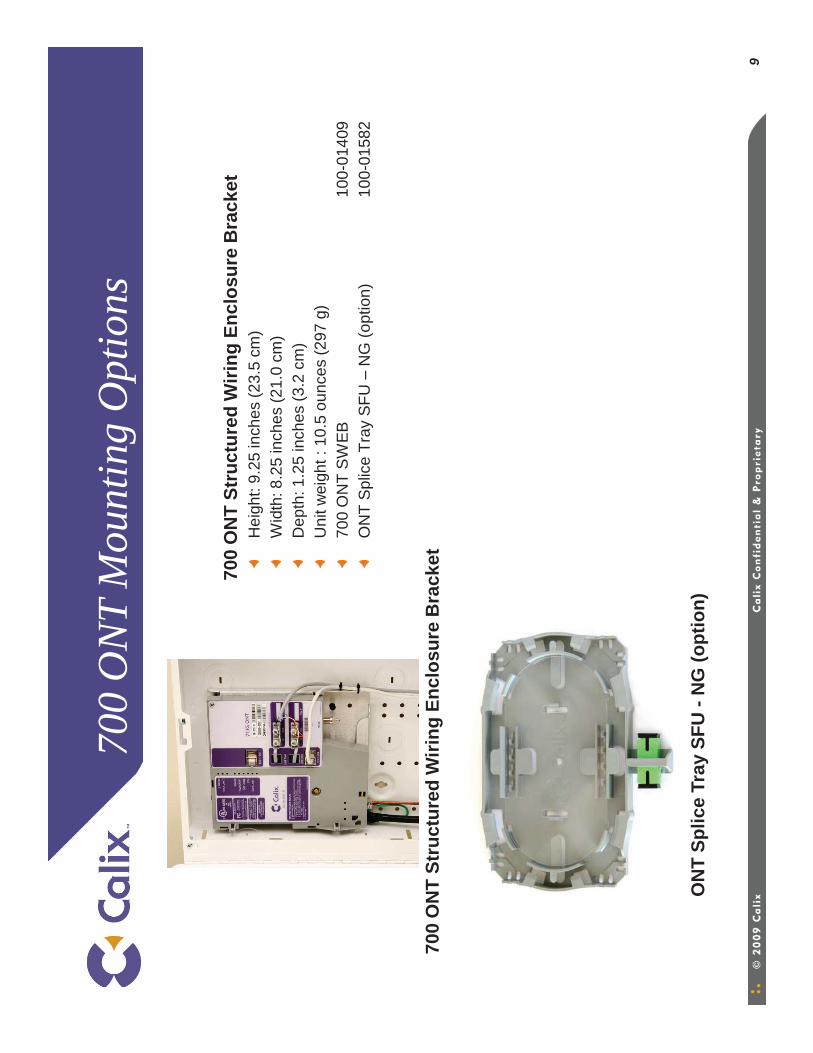
9
700
ON
T M
ount
ing
Opt
ions
700
ON
T St
ruct
ured
Wiri
ng E
nclo
sure
Bra
cket
Hei
ght:
9.25
inch
es (2
3.5
cm)
Wid
th: 8
.25
inch
es (2
1.0
cm)
Dep
th: 1
.25
inch
es (3
.2 c
m)
Uni
t wei
ght :
10.
5 ou
nces
(297
g)
700
ON
T S
WEB
100-
0140
9O
NT
Spl
ice
Tray
SFU
–N
G (o
ptio
n)10
0-01
582
700
ON
T St
ruct
ured
Wiri
ng E
nclo
sure
Bra
cket
ON
T Sp
lice
Tray
SFU
-N
G (o
ptio
n)
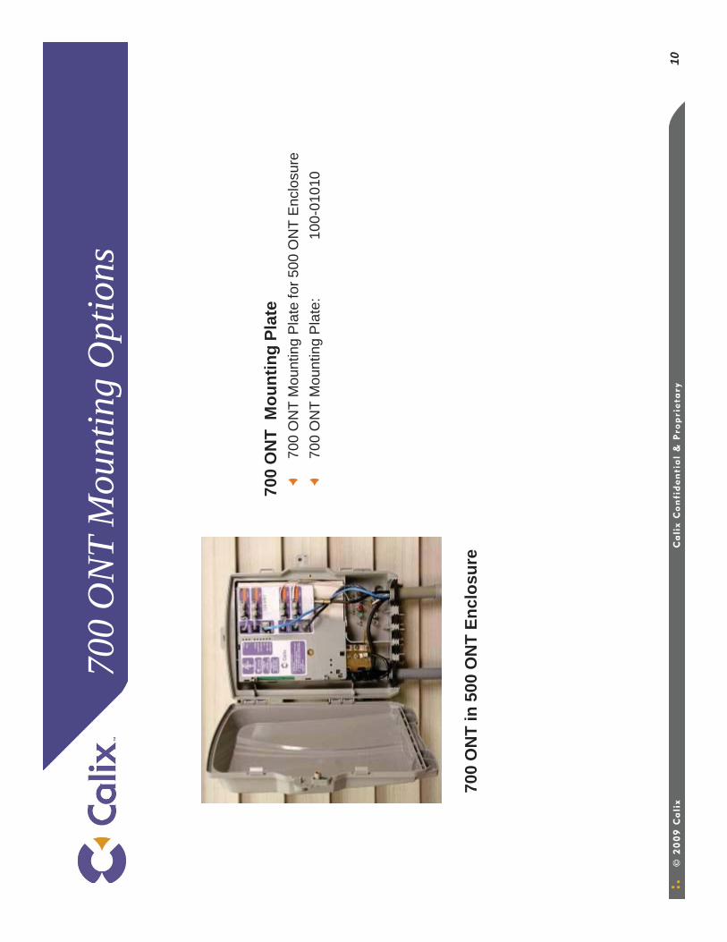
10
700
ON
T M
ount
ing
Opt
ions
700
ON
T M
ount
ing
Plat
e70
0 O
NT
Mou
ntin
g P
late
for 5
00 O
NT
Enc
losu
re70
0 O
NT
Mou
ntin
g P
late
:10
0-01
010
700
ON
T in
500
ON
T En
clos
ure
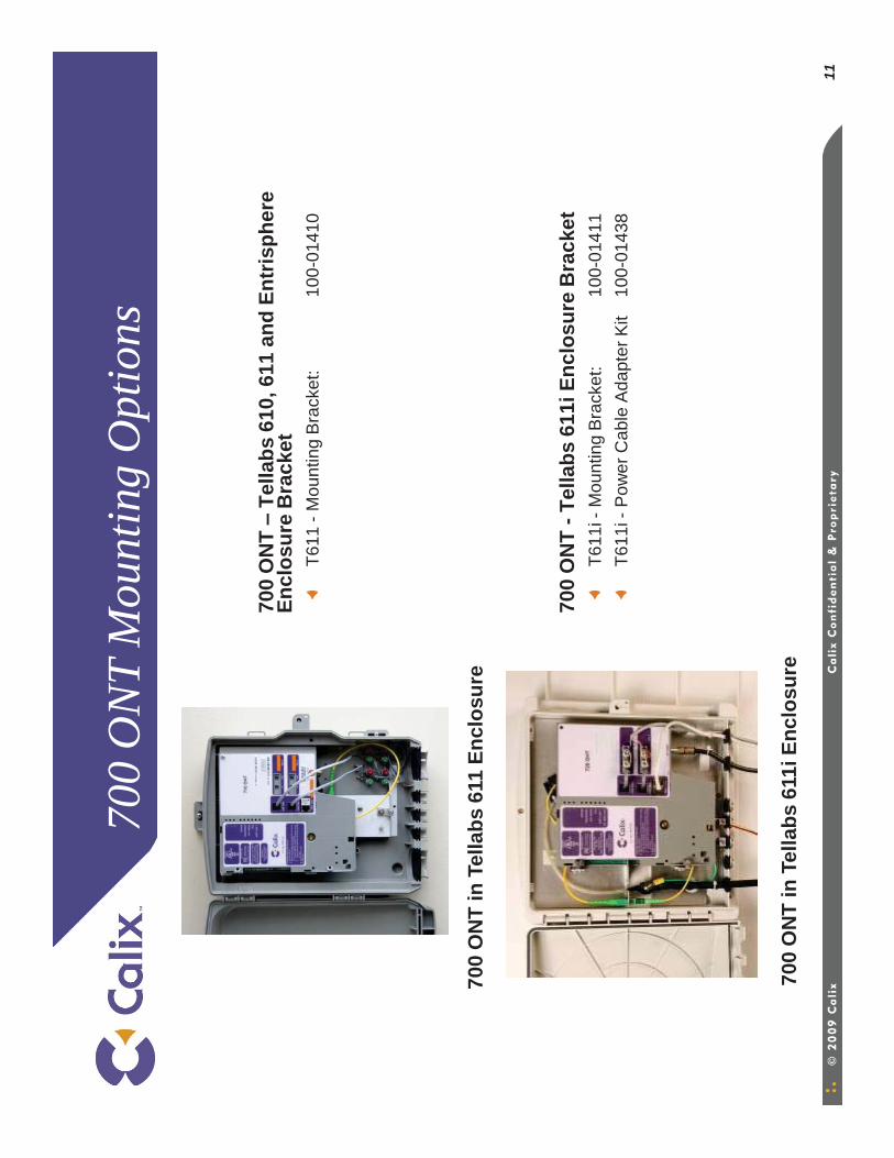
11
700
ON
T M
ount
ing
Opt
ions
700
ON
T –
Tella
bs 6
10, 6
11 a
nd E
ntris
pher
e
Encl
osur
e B
rack
etT6
11 -
Mou
ntin
g B
rack
et:
100-
0141
0
700
ON
T -T
ella
bs 6
11i E
nclo
sure
Bra
cket
T611
i -M
ount
ing
Bra
cket
:10
0-01
411
T611
i -P
ower
Cab
le A
dapt
er K
it 10
0-01
438
700
ON
T in
Tel
labs
611
Enc
losu
re
700
ON
T in
Tel
labs
611
i Enc
losu
re
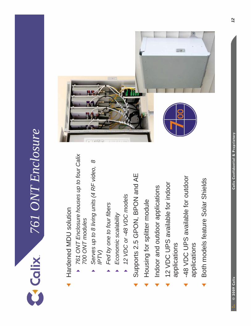
12
761
ON
T En
clos
ure
Har
dene
d M
DU
sol
utio
n76
1 O
NT
Enc
losu
re h
ouse
s up
to fo
ur C
alix
70
0 O
NT
mod
ules
S
erve
s up
to 8
livi
ng u
nits
(4 R
F vi
deo,
8
IPTV
)Fe
d by
one
to fo
ur fi
bers
Eco
nom
ic s
cala
bilit
y12
VD
C o
r -48
VD
C m
odel
s
Sup
ports
2.5
GP
ON
, BP
ON
and
AE
Hou
sing
for s
plitt
er m
odul
eIn
door
and
out
door
app
licat
ions
12 V
DC
UP
S a
vaila
ble
for i
ndoo
r ap
plic
atio
ns-4
8 V
DC
UP
S a
vaila
ble
for o
utdo
or
appl
icat
ions
Bot
h m
odel
s fe
atur
e S
olar
Shi
elds
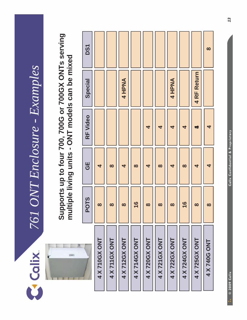
13
761
ON
T En
clos
ure
-Exa
mpl
es
Supp
orts
up
to fo
ur 7
00, 7
00G
or 7
00G
X O
NTs
ser
ving
m
ultip
le li
ving
uni
ts -
ON
T m
odel
s ca
n be
mix
ed
Spec
ial
1
4 X
710G
X O
NT
4 X
711G
X O
NT
4 X
712G
X O
NT
4 X
714G
X O
NT
4 X
720G
X O
NT
4 X
721G
X O
NT
4 X
722G
X O
NT
4 X
724G
X O
NT
4 X
725G
X O
NT
POTS
GE
RF
Vide
oD
S1
84
88
84
4 H
PNA
168
84
4
88
4
84
44
HPN
A
168
4
84
44
RF
Ret
urn
44
X 74
0G O
NT
84
8
14
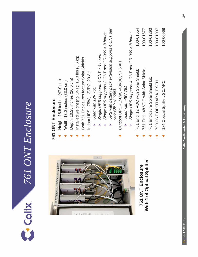
761
ON
T En
clos
ure
761
ON
T En
clos
ure
Hei
ght:
18.5
inch
es (4
7.0
cm)
Wid
th: 1
3.0
inch
es (3
3.0
cm)
Dep
th: 1
0.25
inch
es (2
6.0
cm)
Inst
alle
d w
eigh
t (no
ON
T): 1
5.0
lbs
(6.6
kg)
Bot
h 76
1 E
nclo
sure
s fe
atur
e S
olar
Shi
elds
Indo
or U
PS
-75
W, 1
2VD
C, 2
0 A
HU
sed
with
12V
761
Sin
gle
UP
S s
uppo
rts 4
ON
T >
4 ho
urs
Sin
gle
UP
S s
uppo
rts 2
ON
T pe
r GR
-909
> 8
hou
rsU
PS
with
bat
tery
pac
k ex
tens
ion
supp
orts
4 O
NT
per
GR
-909
> 8
hou
rsO
utdo
or U
PS
-15
0W, -
48V
DC
, 57.
6 A
HU
sed
with
-48V
761
Sin
gle
UP
S s
uppo
rts 4
ON
T pe
r GR
-909
> 8
hou
rs
761
Enc
l 12
VD
C w
ith S
olar
Shi
eld:
100-
0155
4
761
Enc
l -48
VD
C w
ith S
olar
Shi
eld:
100-
0157
7
761
Enc
losu
re S
olar
Shi
eld
kit:
100-
0129
3
700
ON
T O
PTI
TAP
KIT
SFU
10
0-01
097
1x4
Opt
ical
Spl
itter
, SC
/AP
C10
0-00
968
761
ON
T En
clos
ure
With
1x4
Opt
ical
Spl
itter
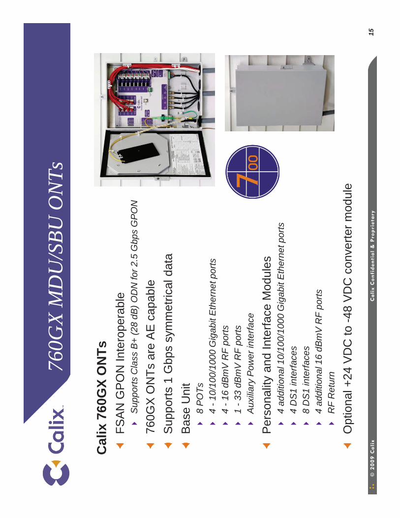
15
760G
X M
DU
/SBU
ON
Ts
Cal
ix76
0GX
ON
TsFS
AN
GP
ON
Inte
rope
rabl
eS
uppo
rts C
lass
B+
(28
dB) O
DN
for 2
.5 G
bps
GP
ON
760G
X O
NTs
are
AE
cap
able
Sup
ports
1 G
bps
sym
met
rical
dat
aB
ase
Uni
t8
PO
Ts4
-10/
100/
1000
Gig
abit
Eth
erne
t por
ts4
-16
dBm
V R
F po
rts1
-33
dBm
V R
F po
rts
Aux
iliar
y P
ower
inte
rface
Per
sona
lity
and
Inte
rface
Mod
ules
4 ad
ditio
nal 1
0/10
0/10
00 G
igab
it E
ther
net p
orts
4 D
S1
inte
rface
s8
DS
1 in
terfa
ces
4 ad
ditio
nal 1
6 dB
mV
RF
ports
RF
Ret
urn
Opt
iona
l +24
VD
C to
-48
VD
C c
onve
rter m
odul
e
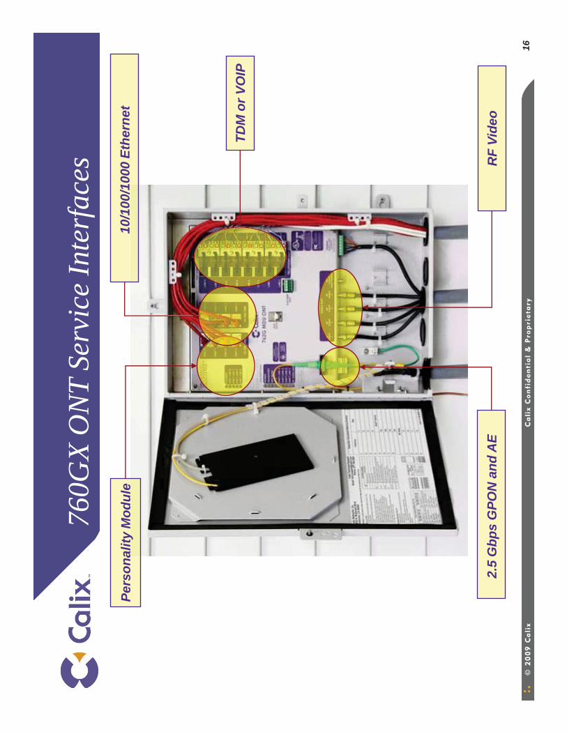
16
760G
X O
NT
Serv
ice
Inte
rfac
es
2.5
Gbp
sG
PON
and
AE
RF
Vide
o
Pers
onal
ity M
odul
e
TDM
or V
OIP
10/1
00/1
000
Ethe
rnet
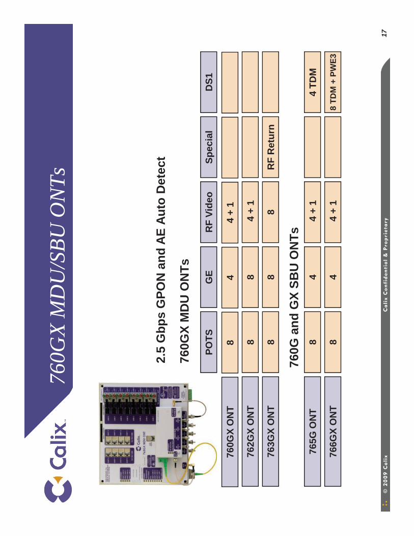
17
760G
X M
DU
/SBU
ON
Ts
760G
X M
DU
ON
Ts
Spec
ial
4 +
176
0GX
ON
T
762G
X O
NT
POTS
GE
RF
Vide
oD
S1
84
88
4 +
1
4 TD
M
8 TD
M +
PW
E3
765G
ON
T
766G
X O
NT
84
4 +
1
84
4 +
1
8R
F R
etur
n76
3GX
ON
T8
8
760G
and
GX
SBU
ON
Ts
2.5
Gbp
sG
PON
and
AE
Auto
Det
ect
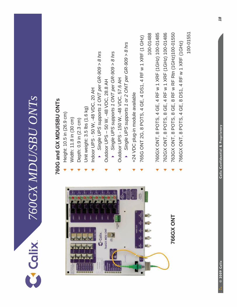
18
760G
X M
DU
/SBU
ON
Ts
760G
and
GX
MD
U/S
BU
ON
TsH
eigh
t: 10
.5 in
(26.
9 cm
)W
idth
: 11.
8 in
(30
cm)
Dep
th: 0
.9 in
(2.3
cm
)U
nit w
eigh
t: 3.
5 lb
s (1
.6 k
g)In
door
UP
S -
50 W
, -48
VD
C, 2
0 A
HS
ingl
e U
PS
sup
ports
1 O
NT
per G
R-9
09 >
8 h
rs
Out
door
UP
S –
50 W
, -48
VD
C, 2
8.8
AH
Sin
gle
UP
S s
uppo
rts 1
ON
T pe
r GR
-909
> 8
hrs
Out
door
UP
S -
150
W, -
48 V
DC
, 57.
6 A
HS
ingl
e U
PS
sup
ports
1 o
r 2 O
NT
per G
R-9
09 >
8 h
rs
+24
VD
C p
lug-
in m
odul
e av
aila
ble
765G
ON
T 2G
, 8 P
OTS
, 4 G
E, 4
DS
1, 4
RF
w 1
XR
F (1
GH
z)
100-
0148
8
760G
X O
NT,
8 P
OTS
, 4 G
E, 4
RF
w 1
XR
F (1
GH
z) 1
00-0
1485
762G
X O
NT,
8 P
OTS
, 8 G
E, 4
RF
w 1
XR
F (1
GH
z) 1
00-0
1486
763G
X O
NT,
8 P
OTS
, 8 G
E, 8
RF
w R
F R
tn (1
GH
z)10
0-01
550
766G
X O
NT,
8 P
OTS
, 4 G
E, 8
DS
1, 4
RF
w 1
XR
F (1
GH
z)
100-
0155
1
766G
X O
NT
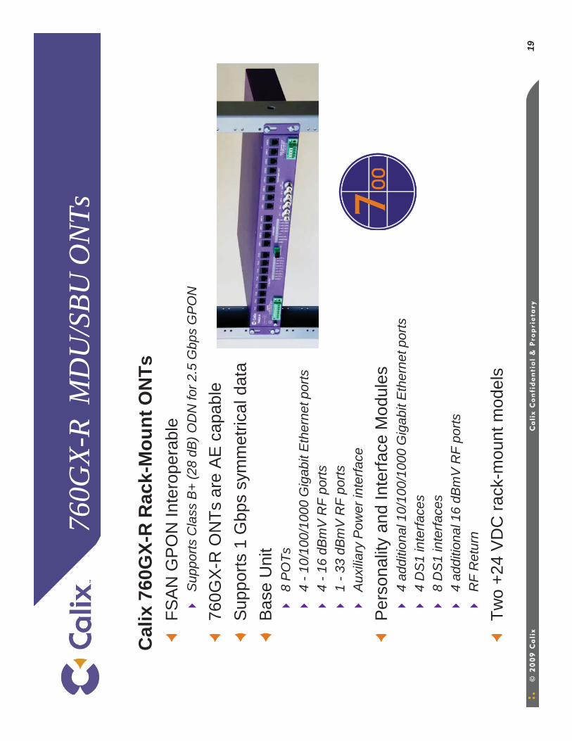
19
760G
X-R
MD
U/S
BU O
NTs
Cal
ix76
0GX-
R R
ack-
Mou
nt O
NTs
FSA
N G
PO
N In
tero
pera
ble
Sup
ports
Cla
ss B
+ (2
8 dB
) OD
N fo
r 2.5
Gbp
s G
PO
N
760G
X-R
ON
Ts a
re A
E c
apab
leS
uppo
rts 1
Gbp
s sy
mm
etric
al d
ata
Bas
e U
nit
8 P
OTs
4 -1
0/10
0/10
00 G
igab
it E
ther
net p
orts
4 -1
6 dB
mV
RF
ports
1 -3
3 dB
mV
RF
ports
A
uxili
ary
Pow
er in
terfa
ce
Per
sona
lity
and
Inte
rface
Mod
ules
4 ad
ditio
nal 1
0/10
0/10
00 G
igab
it E
ther
net p
orts
4 D
S1
inte
rface
s8
DS
1 in
terfa
ces
4 ad
ditio
nal 1
6 dB
mV
RF
ports
RF
Ret
urn
Two
+24
VD
C ra
ck-m
ount
mod
els
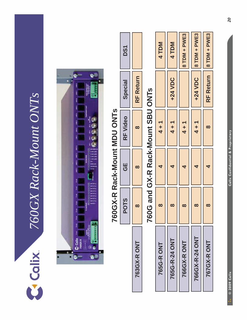
20
760G
and
GX-
R R
ack-
Mou
nt S
BU
ON
Ts
8 TD
M +
PW
E376
6GX-
R O
NT
84
4 +
1
+24
VDC
8 TD
M +
PW
E376
6GX-
R-2
4 O
NT
84
4 +
1
760G
and
GX
MD
U/S
BU O
NT
760G
X-R
Rac
k-M
ount
MD
U O
NTs
Sp
ecia
l
RF
Ret
urn
763G
X-R
ON
T
POTS
GE
RF
Vide
oD
S1
88
8
+24
VDC
4 TD
M76
5G-R
-24
ON
T8
44
+ 1
4 TD
M76
5G-R
ON
T8
44
+ 1
RF
Ret
urn
8 TD
M +
PW
E376
7GX-
R O
NT
84
8
760G
X Ra
ck-M
ount
ON
Ts
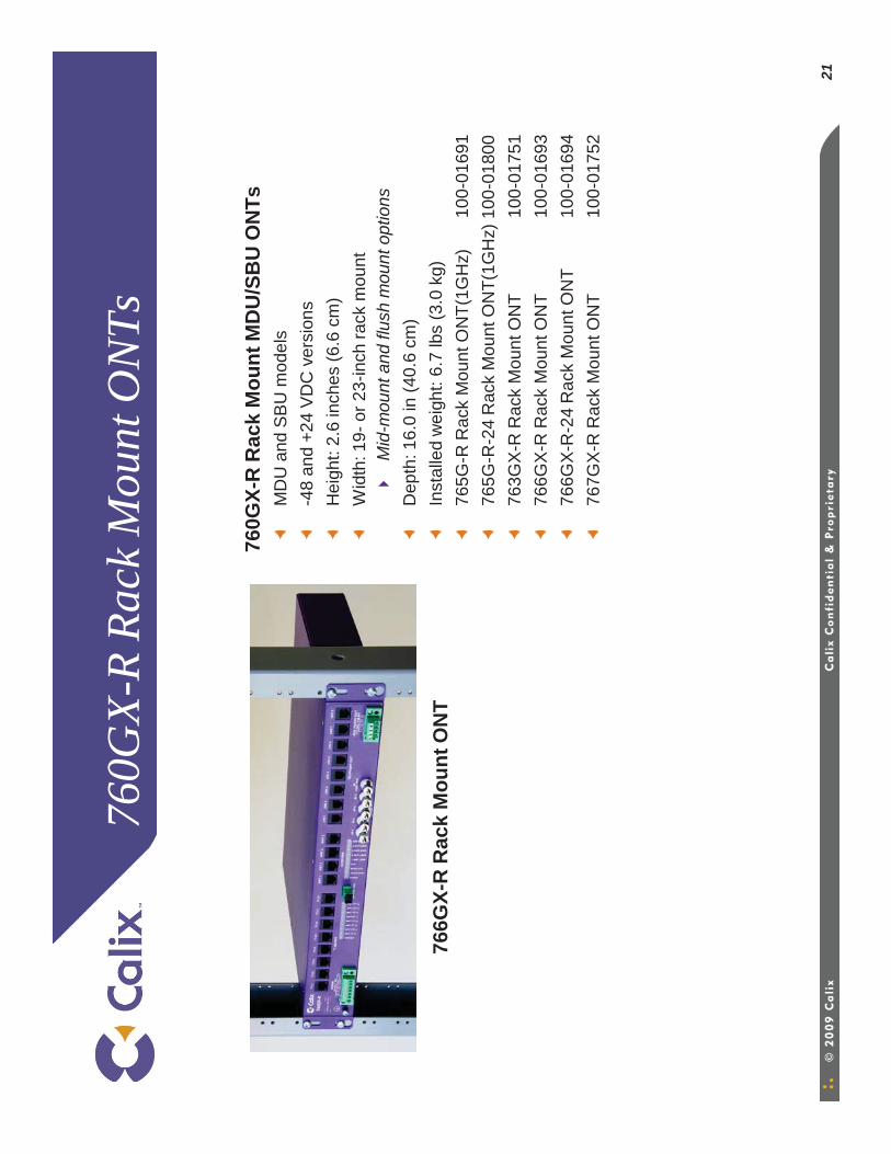
21
760G
X-R
Rack
Mou
nt O
NTs
760G
X-R
Rac
k M
ount
MD
U/S
BU
ON
TsM
DU
and
SB
U m
odel
s -4
8 an
d +2
4 V
DC
ver
sion
sH
eigh
t: 2.
6 in
ches
(6.6
cm
)W
idth
: 19-
or 2
3-in
ch ra
ck m
ount
M
id-m
ount
and
flus
h m
ount
opt
ions
Dep
th: 1
6.0
in (4
0.6
cm)
Inst
alle
d w
eigh
t: 6.
7 lb
s (3
.0 k
g)
765G
-R R
ack
Mou
nt O
NT(
1GH
z)10
0-01
691
765G
-R-2
4 R
ack
Mou
nt O
NT(
1GH
z) 1
00-0
1800
763G
X-R
Rac
k M
ount
ON
T10
0-01
751
766G
X-R
Rac
k M
ount
ON
T10
0-01
693
766G
X-R
-24
Rac
k M
ount
ON
T10
0-01
694
767G
X-R
Rac
k M
ount
ON
T10
0-01
752
766G
X-R
Rac
k M
ount
ON
T
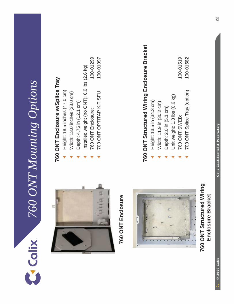
22
760
ON
T M
ount
ing
Opt
ions
760
ON
T En
clos
ure
w/S
plic
e Tr
ayH
eigh
t: 18
.5 in
ches
(47.
0 cm
)W
idth
: 13.
0 in
ches
(33.
0 cm
)D
epth
: 4.7
5 in
(12.
1 cm
)In
stal
led
wei
ght (
no O
NT)
: 6.0
lbs
(2.6
kg)
760
ON
T E
nclo
sure
:10
0-01
299
700
ON
T O
PTI
TAP
KIT
SFU
10
0-01
097
760
ON
T St
ruct
ured
Wiri
ng E
nclo
sure
Bra
cket
Hei
ght:
13.5
in (3
4.3
cm)
Wid
th: 1
1.9
in (3
0.2
cm)
Dep
th: 2
.0 in
(5.1
cm
)U
nit w
eigh
t: 1.
3 lb
s (0
.6 k
g)76
0 O
NT
SW
EB:
100-
0151
970
0 O
NT
Spl
ice
Tray
(opt
ion)
100-
0158
2
760
ON
T En
clos
ure
760
ON
T St
ruct
ured
Wiri
ng
Encl
osur
e B
rack
et
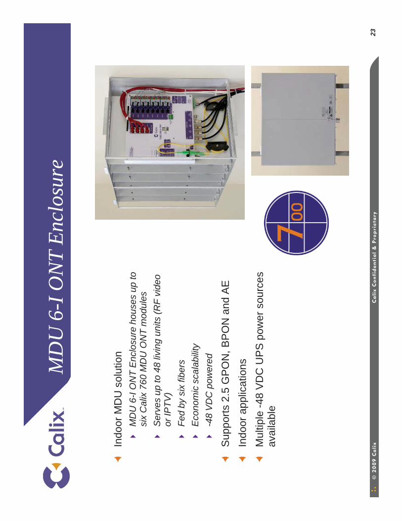
23
MD
U 6
-I O
NT
Encl
osur
e
Indo
or M
DU
sol
utio
nM
DU
6-I
ON
T E
nclo
sure
hou
ses
up to
si
x C
alix
760
MD
U O
NT
mod
ules
S
erve
s up
to 4
8 liv
ing
units
(RF
vide
o or
IPTV
)Fe
d by
six
fibe
rsE
cono
mic
sca
labi
lity
-48
VD
C p
ower
ed
Sup
ports
2.5
GP
ON
, BP
ON
and
AE
Indo
or a
pplic
atio
nsM
ultip
le -4
8 V
DC
UP
S p
ower
sou
rces
av
aila
ble
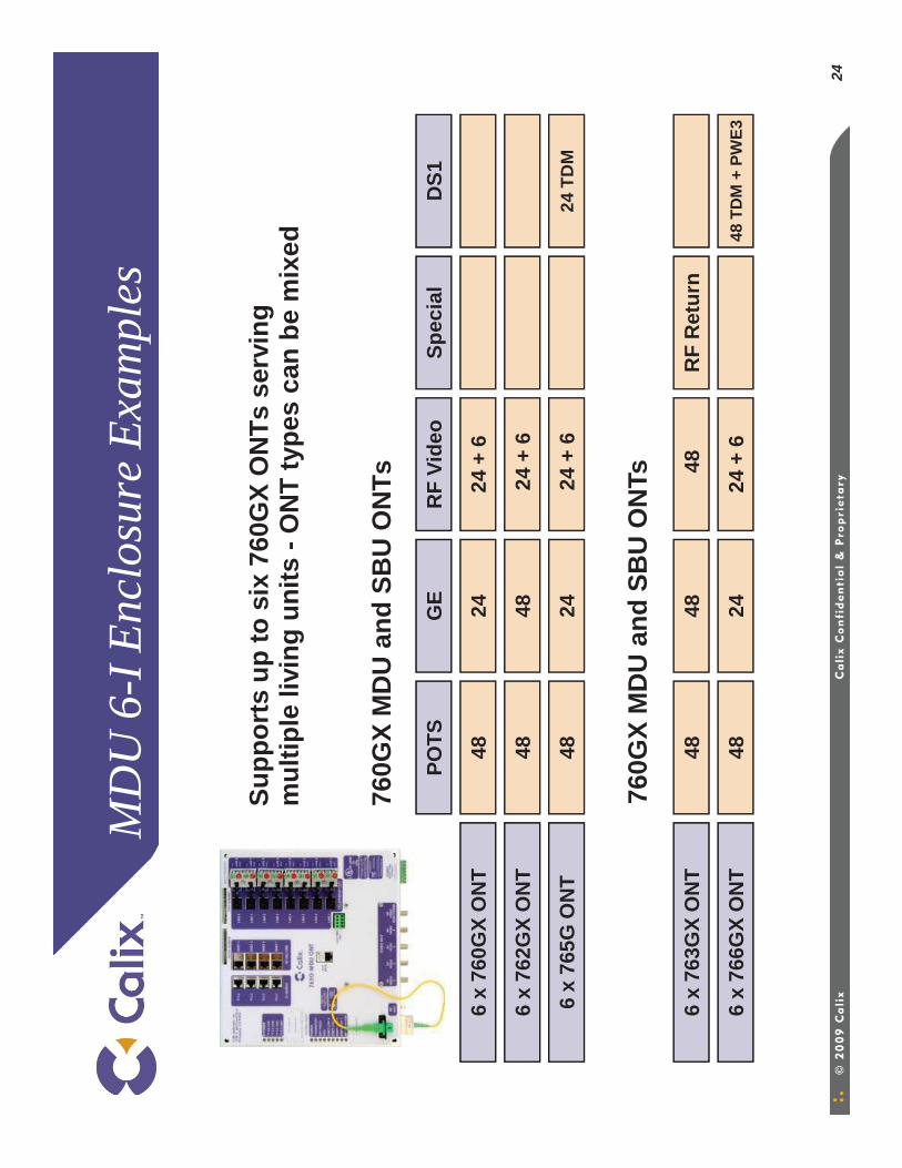
24
MD
U 6
-I E
nclo
sure
Exa
mpl
es
Supp
orts
up
to s
ix 7
60G
X O
NTs
ser
ving
m
ultip
le li
ving
uni
ts -
ON
T ty
pes
can
be m
ixed
760G
X M
DU
and
SB
U O
NTs
Spec
ial
24 +
6
24 T
DM
6 x
760G
X O
NT
6 x
762G
X O
NT
6 x
765G
ON
T
POTS
GE
RF
Vide
oD
S1
4824
4848
24 +
6
4824
24 +
6
RF
Ret
urn
48 T
DM
+ P
WE3
6 x
763G
X O
NT
6 x
766G
X O
NT
4848
48
4824
24 +
6
760G
X M
DU
and
SB
U O
NTs
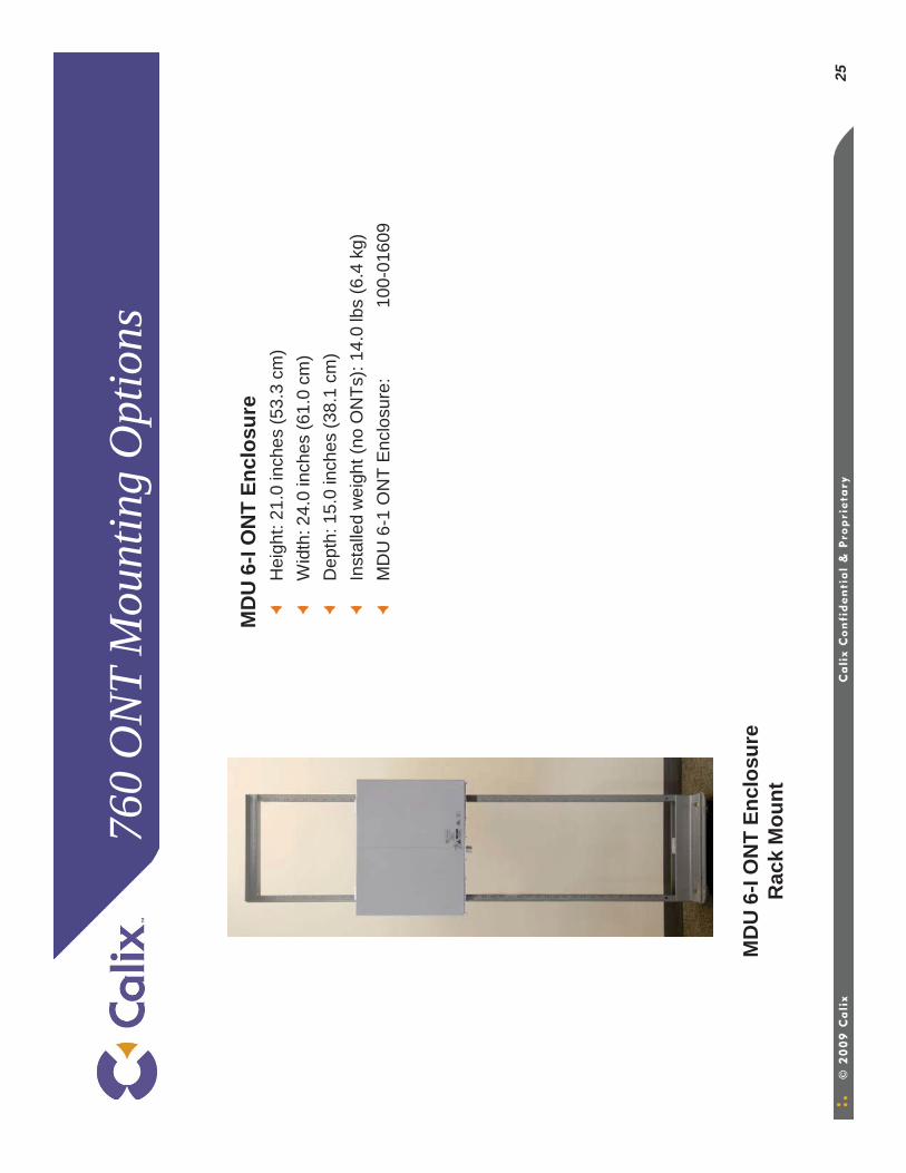
25
760
ON
T M
ount
ing
Opt
ions
MD
U 6
-I O
NT
Encl
osur
eH
eigh
t: 21
.0 in
ches
(53.
3 cm
)W
idth
: 24.
0 in
ches
(61.
0 cm
)D
epth
: 15.
0 in
ches
(38.
1 cm
)In
stal
led
wei
ght (
no O
NTs
): 14
.0 lb
s (6
.4 k
g)M
DU
6-1
ON
T E
nclo
sure
:10
0-01
609
MD
U 6
-I O
NT
Encl
osur
e R
ack
Mou
nt
ON
T P
ower
ing
Opt
ions
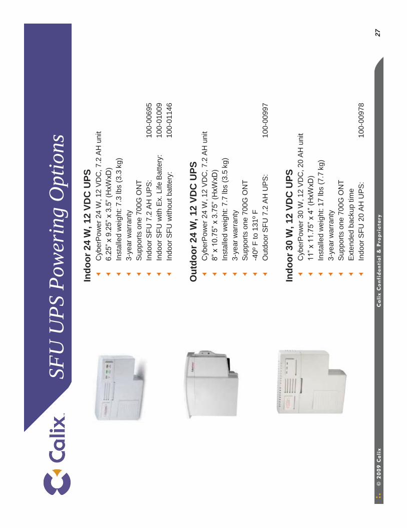
27
SFU
UPS
Pow
erin
g O
ptio
nsIn
door
24
W, 1
2 VD
C U
PSC
yber
Pow
er 2
4 W
, 12
VD
C, 7
.2 A
H u
nit
6.25
” x 9
.25”
x 3
.5” (
HxW
xD)
Inst
alle
d w
eigh
t: 7.
3 lb
s (3
.3 k
g)3-
year
war
rant
ySu
ppor
ts o
ne 7
00G
ON
T In
door
SFU
7.2
AH
UPS
:10
0-00
695
Indo
or S
FU w
ith E
x. L
ife B
atte
ry:
100-
0100
9In
door
SFU
with
out b
atte
ry:
100-
0114
6
Out
door
24
W, 1
2 VD
C U
PS
Cyb
erPo
wer
24
W, 1
2 VD
C, 7
.2 A
H u
nit
8” x
10.
75” x
3.7
5” (H
xWxD
)In
stal
led
wei
ght:
7.7
lbs
(3.5
kg)
3-
year
war
rant
ySu
ppor
ts o
ne 7
00G
ON
T-4
0º F
to 1
31ºF
Out
door
SFU
7.2
AH
UPS
:10
0-00
997
Indo
or 3
0 W
, 12
VDC
UPS
Cyb
erPo
wer
30
W, 1
2 VD
C, 2
0 AH
uni
t11
” x 1
1.75
” x 4
” (H
xWxD
)In
stal
led
wei
ght:
17 lb
s (7
.7 k
g)
3-ye
ar w
arra
nty
Supp
orts
one
700
G O
NT
Exte
nded
bac
kup
time
Indo
or S
FU 2
0 AH
UPS
:10
0-00
978
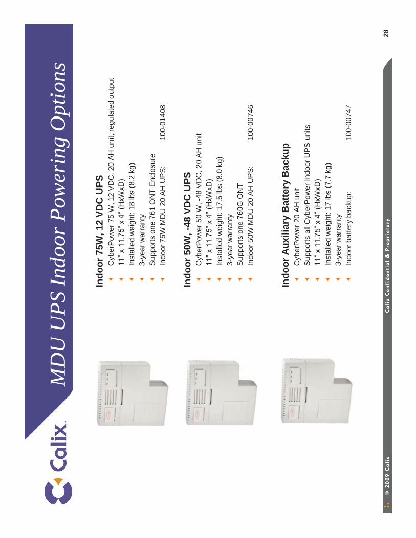
28
MD
U U
PS In
door
Pow
erin
g O
ptio
ns
Indo
or 7
5W, 1
2 VD
C U
PS
Cyb
erPo
wer
75
W, 1
2 VD
C, 2
0 A
H u
nit,
regu
late
d ou
tput
11” x
11.
75” x
4” (
HxW
xD)
Inst
alle
d w
eigh
t: 18
lbs
(8.2
kg)
3-
year
war
rant
yS
uppo
rts o
ne 7
61 O
NT
Enc
losu
reIn
door
75W
MD
U 2
0 AH
UPS
:10
0-01
408
Indo
or 5
0W, -
48 V
DC
UPS
C
yber
Pow
er 5
0 W
, -48
VD
C, 2
0 AH
uni
t11
” x 1
1.75
” x 4
” (H
xWxD
)In
stal
led
wei
ght:
17.5
lbs
(8.0
kg)
3-
year
war
rant
ySu
ppor
ts o
ne 7
60G
ON
TIn
door
50W
MD
U 2
0 AH
UPS
:10
0-00
746
Indo
or A
uxili
ary
Bat
tery
Bac
kup
Cyb
erPo
wer
20
AH u
nit
Supp
orts
all
Cyb
erPo
wer
Indo
or U
PS u
nits
11” x
11.
75” x
4” (
HxW
xD)
Inst
alle
d w
eigh
t: 17
lbs
(7.7
kg)
3-
year
war
rant
yIn
door
bat
tery
bac
kup:
100-
0074
7
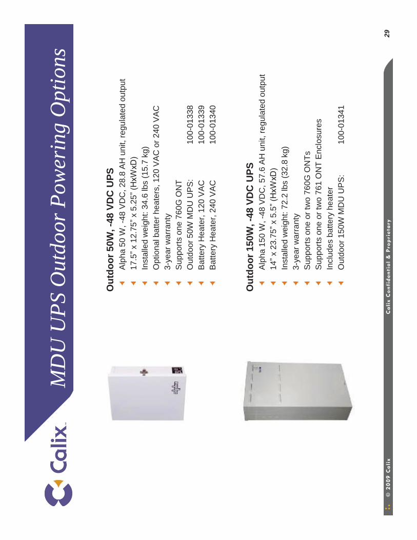
29
MD
U U
PS O
utdo
or P
ower
ing
Opt
ions
Out
door
50W
, -48
VD
C U
PSA
lpha
50
W, -
48 V
DC
, 28.
8 A
H u
nit,
regu
late
d ou
tput
17.5
”x 1
2.75
”x 5
.25”
(HxW
xD)
Inst
alle
d w
eigh
t: 34
.6 lb
s (1
5.7
kg)
Opt
iona
l bat
ter h
eate
rs, 1
20 V
AC
or 2
40 V
AC
3-ye
ar w
arra
nty
Sup
ports
one
760
G O
NT
Out
door
50W
MD
U U
PS
:10
0-01
338
Bat
tery
Hea
ter,
120
VA
C10
0-01
339
Bat
tery
Hea
ter,
240
VA
C10
0-01
340
Out
door
150
W, -
48 V
DC
UPS
A
lpha
150
W, -
48 V
DC
, 57.
6 A
H u
nit,
regu
late
d ou
tput
14”x
23.
75”x
5.5
” (H
xWxD
)In
stal
led
wei
ght:
72.2
lbs
(32.
8 kg
)3-
year
war
rant
yS
uppo
rts o
ne o
r tw
o 76
0G O
NTs
S
uppo
rts o
ne o
r tw
o 76
1 O
NT
Enc
losu
res
Incl
udes
bat
tery
hea
ter
Out
door
150
W M
DU
UP
S:
100-
0134
1
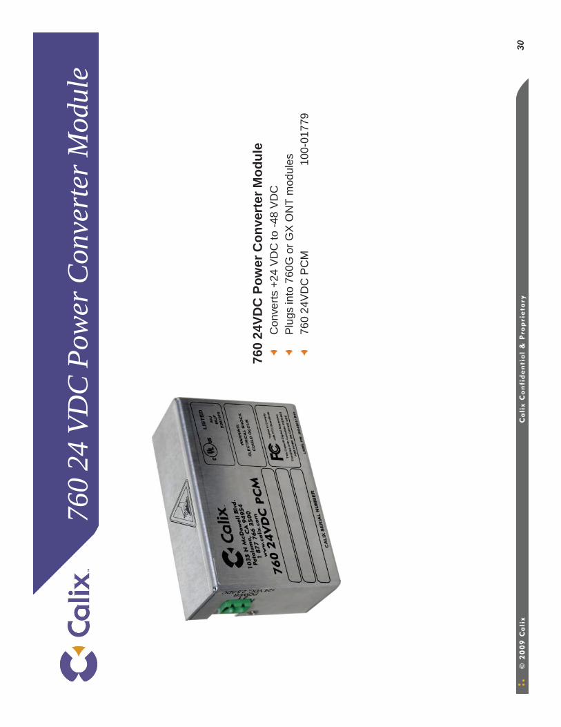
30
760
24 V
DC
Pow
er C
onve
rter
Mod
ule
760
24VD
C P
ower
Con
vert
er M
odul
eC
onve
rts +
24 V
DC
to -4
8 V
DC
Plu
gs in
to 7
60G
or G
X O
NT
mod
ules
760
24V
DC
PC
M10
0-01
779
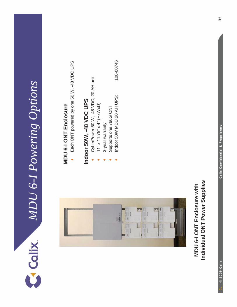
31
MD
U 6
-I P
ower
ing
Opt
ions
MD
U 6
-I O
NT
Encl
osur
eEa
ch O
NT
pow
ered
by
one
50 W
, -48
VD
C U
PS
Indo
or 5
0W, -
48 V
DC
UPS
C
yber
Pow
er 5
0 W
, -48
VD
C, 2
0 AH
uni
t11
” x 1
1.75
” x 4
” (H
xWxD
)3-
year
war
rant
yS
uppo
rts o
ne 7
60G
ON
TIn
door
50W
MD
U 2
0 AH
UPS
:10
0-00
746
MD
U 6
-I O
NT
Encl
osur
e w
ith
Indi
vidu
al O
NT
Pow
er S
uppl
ies

32
MD
U 6
-I P
ower
ing
Opt
ions
MD
U 6
-I O
NT
Encl
osur
e Po
wer
Sup
ply
Up
to s
ix 7
60 O
NTs
pow
ered
by
one
350
W, -
48 V
DC
rect
ifier
w
/bat
tery
bac
kup
Elte
k Va
lere
7 A
, 350
W, -
48 V
DC
Rec
tifie
r w
/Bat
tery
Bac
kup
Kit
Incl
udes
:R
ectif
ier a
nd d
istri
butio
n en
clos
ure
(2 R
U)
Bat
tery
enc
losu
re fo
r fou
r, 40
or 3
3 A
H b
atte
ries
(6 R
U)
40 A
H B
atte
ry S
tring
(fou
r 12
V b
atte
ries)
One
7 A
mp
rect
ifier
; opt
iona
l sec
ond
rect
ifier
mod
ule
avai
labl
e fo
r pow
er re
dund
ancy
ON
T po
wer
dis
tribu
tion
and
alar
ms
cabl
e ha
rnes
s O
ne 1
0 A
mp
GM
T fu
seSu
ppor
ts u
p to
six
760
G O
NTs
MD
U 6
-I Po
wer
Sys
tem
and
Cab
le K
it:
000
-003
19
MD
U R
ectif
ier M
odul
e 7A
(for
redu
ndan
cy)
100
-015
64
MD
U 6
-I O
NT
Encl
osur
e w
ith
Elte
k Va
lere
Pow
er S
uppl
y
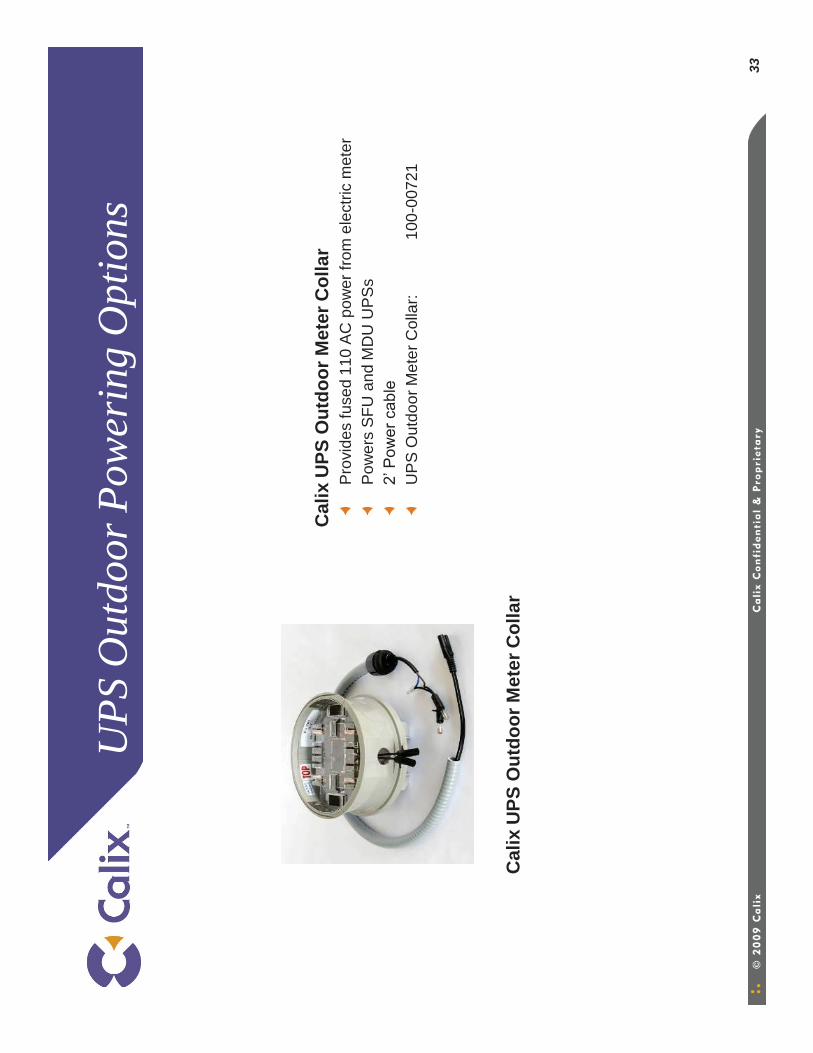
33
UPS
Out
door
Pow
erin
g O
ptio
ns
Cal
ix U
PS O
utdo
or M
eter
Col
lar
Pro
vide
s fu
sed
110
AC
pow
er fr
om e
lect
ric m
eter
Pow
ers
SFU
and
MD
U U
PS
s2’
Pow
er c
able
UP
S O
utdo
or M
eter
Col
lar:
100-
0072
1
Cal
ix U
PS O
utdo
or M
eter
Col
lar
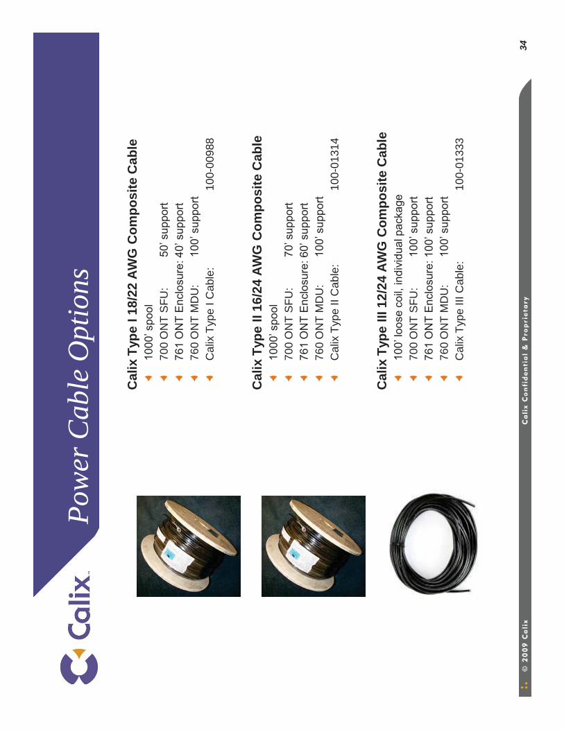
34
Pow
er C
able
Opt
ions
Cal
ix T
ype
I 18/
22 A
WG
Com
posi
te C
able
1000
’ spo
ol70
0 O
NT
SFU
: 50
’ sup
port
761
ON
T E
nclo
sure
: 40’
sup
port
760
ON
T M
DU
: 10
0’ s
uppo
rtC
alix
Typ
e I C
able
:10
0-00
988
Cal
ix T
ype
II 16
/24
AWG
Com
posi
te C
able
1000
’ spo
ol70
0 O
NT
SFU
: 70
’ sup
port
761
ON
T E
nclo
sure
: 60’
sup
port
760
ON
T M
DU
: 10
0’ s
uppo
rtC
alix
Typ
e II
Cab
le:
100-
0131
4
Cal
ix T
ype
III 1
2/24
AW
G C
ompo
site
Cab
le10
0’ lo
ose
coil,
indi
vidu
al p
acka
ge70
0 O
NT
SFU
: 10
0’ s
uppo
rt76
1 O
NT
Enc
losu
re: 1
00’ s
uppo
rt76
0 O
NT
MD
U:
100’
sup
port
Cal
ix T
ype
III C
able
:10
0-01
333
700
and
760
ON
T A
cces
sorie
s
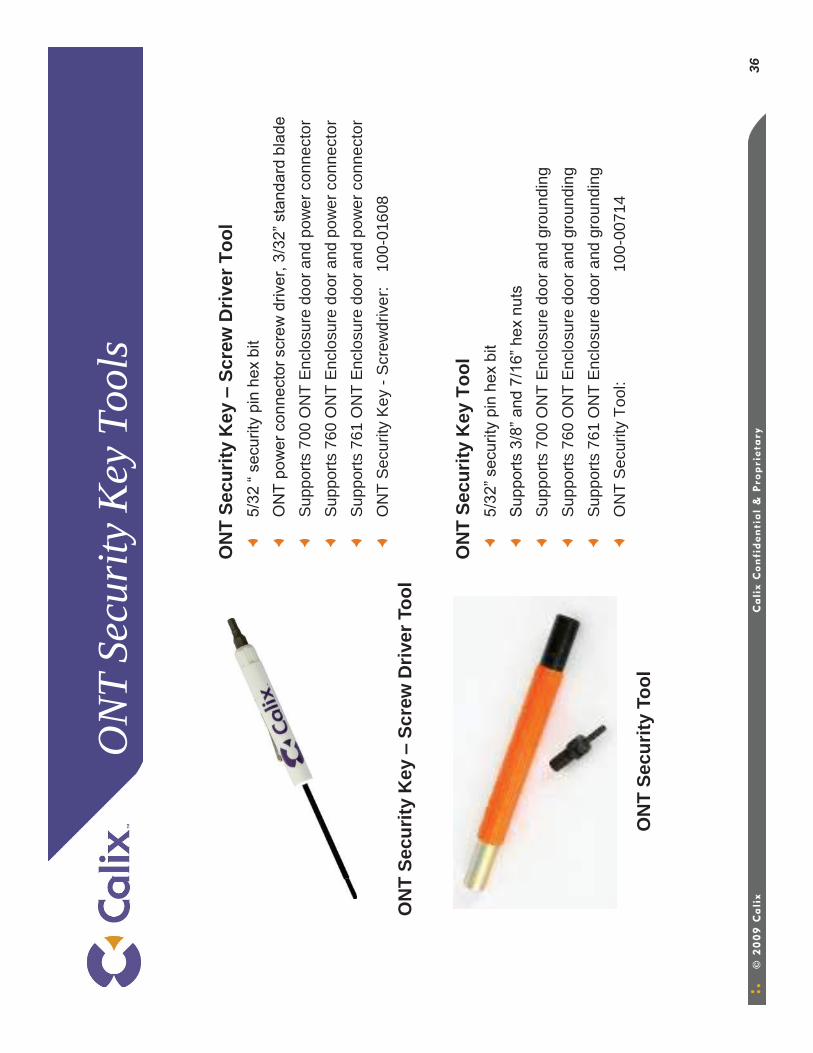
36
ON
T Se
curi
ty K
ey T
ools
ON
T Se
curit
y K
ey –
Scre
w D
river
Too
l5/
32 “
secu
rity
pin
hex
bit
ON
T po
wer
con
nect
or s
crew
driv
er, 3
/32”
sta
ndar
d bl
ade
Sup
ports
700
ON
T E
nclo
sure
doo
r and
pow
er c
onne
ctor
Sup
ports
760
ON
T E
nclo
sure
doo
r and
pow
er c
onne
ctor
Sup
ports
761
ON
T E
nclo
sure
doo
r and
pow
er c
onne
ctor
ON
T S
ecur
ity K
ey -
Scr
ewdr
iver
: 10
0-01
608
ON
T Se
curit
y K
ey T
ool
5/32
” sec
urity
pin
hex
bit
Sup
ports
3/8
” and
7/1
6” h
ex n
uts
Sup
ports
700
ON
T E
nclo
sure
doo
r and
gro
undi
ngS
uppo
rts 7
60 O
NT
Enc
losu
re d
oor a
nd g
roun
ding
Sup
ports
761
ON
T E
nclo
sure
doo
r and
gro
undi
ngO
NT
Sec
urity
Too
l:10
0-00
714
ON
T Se
curit
y K
ey –
Scre
w D
river
Too
l
ON
T Se
curit
y To
ol
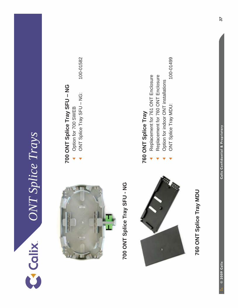
37
ON
T Sp
lice
Tray
s
700
ON
T Sp
lice
Tray
SFU
–N
GO
ptio
n fo
r 700
SW
EB
ON
T S
plic
e Tr
ay S
FU –
NG
:10
0-01
582
760
ON
T Sp
lice
Tray
Rep
lace
men
t for
761
ON
T E
nclo
sure
Rep
lace
men
t for
760
ON
T E
nclo
sure
Opt
ion
for i
ndoo
r ON
T in
stal
latio
nsO
NT
Spl
ice
Tray
MD
U:
100-
0149
9
700
ON
T Sp
lice
Tray
SFU
-N
G
760
ON
T Sp
lice
Tray
MD
U
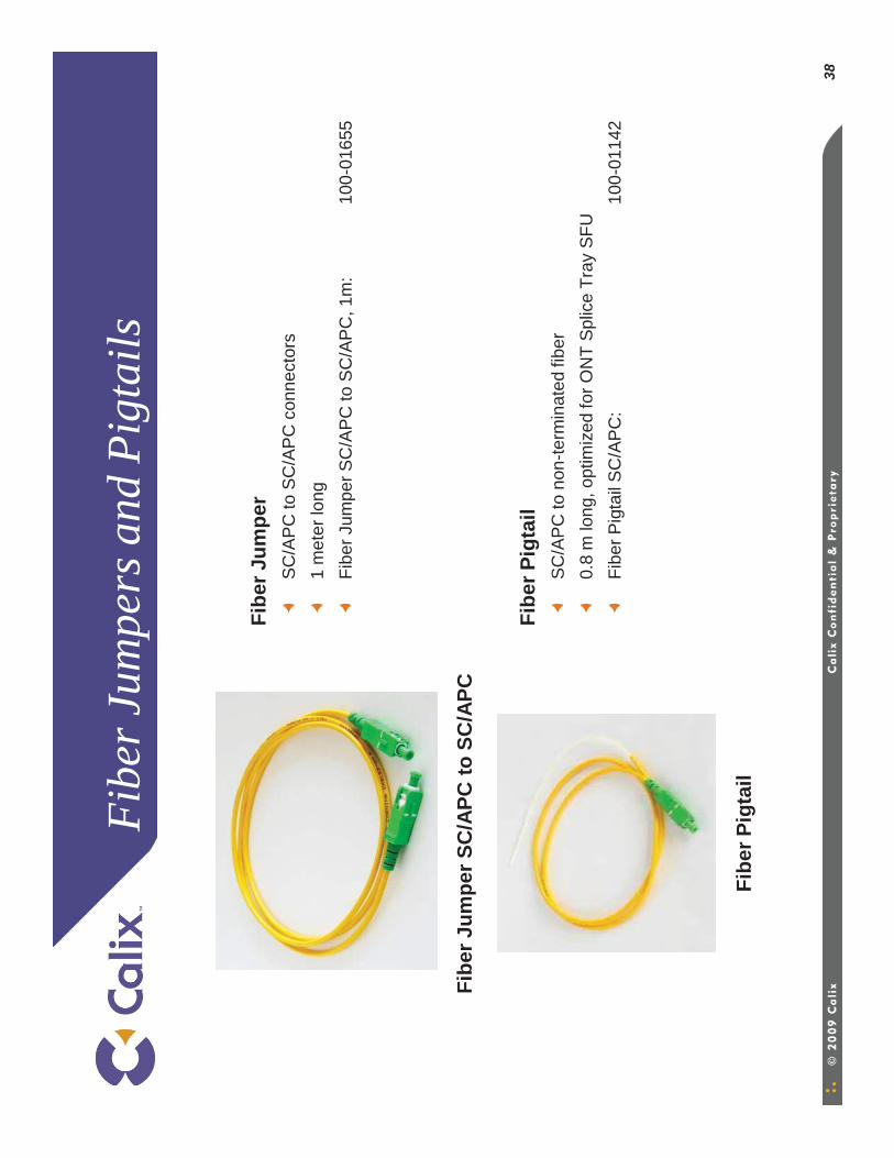
38
Fibe
r Jum
pers
and
Pig
tails
Fibe
r Jum
per
SC
/AP
C to
SC
/AP
C c
onne
ctor
s1
met
er lo
ngFi
ber J
umpe
r SC
/AP
C to
SC
/AP
C, 1
m:
100-
0165
5
Fibe
r Pig
tail
SC
/AP
C to
non
-term
inat
ed fi
ber
0.8
m lo
ng, o
ptim
ized
for O
NT
Spl
ice
Tray
SFU
Fibe
r Pig
tail
SC
/AP
C:
100-
0114
2
Fibe
r Pig
tail
Fibe
r Jum
per S
C/A
PC to
SC
/APC
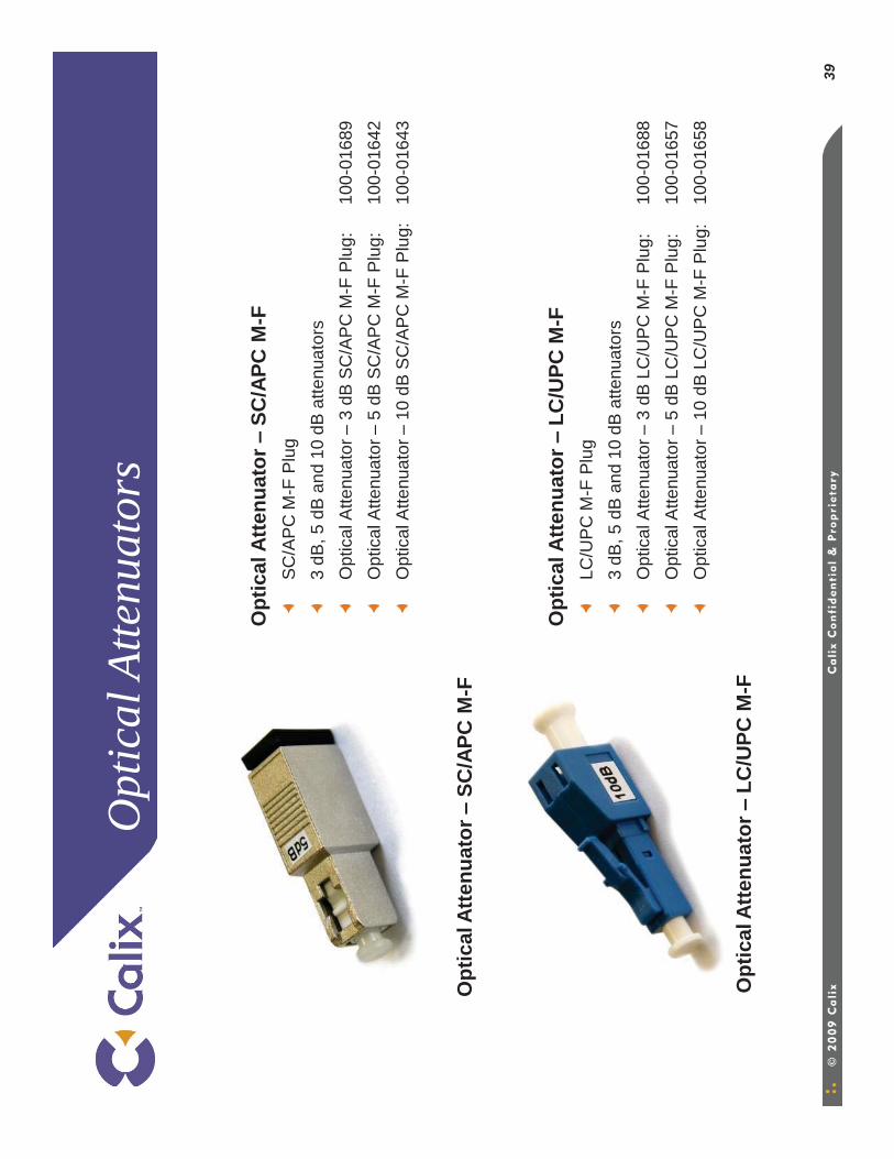
39
Opt
ical
Atte
nuat
ors
Opt
ical
Atte
nuat
or –
SC/A
PC M
-FS
C/A
PC
M-F
Plu
g3
dB, 5
dB
and
10
dB a
ttenu
ator
sO
ptic
al A
ttenu
ator
–3
dB S
C/A
PC
M-F
Plu
g:10
0-01
689
Opt
ical
Atte
nuat
or–
5 dB
SC
/AP
C M
-F P
lug:
100-
0164
2O
ptic
al A
ttenu
ator
–10
dB
SC
/AP
C M
-F P
lug:
100-
0164
3
Opt
ical
Atte
nuat
or –
LC/U
PC M
-FLC
/UP
C M
-F P
lug
3 dB
, 5 d
B a
nd 1
0 dB
atte
nuat
ors
Opt
ical
Atte
nuat
or–
3 dB
LC
/UP
C M
-F P
lug:
100-
0168
8O
ptic
al A
ttenu
ator
–5
dB L
C/U
PC
M-F
Plu
g:10
0-01
657
Opt
ical
Atte
nuat
or–
10 d
B L
C/U
PC
M-F
Plu
g:10
0-01
658
Opt
ical
Atte
nuat
or –
LC/U
PC M
-F
Opt
ical
Atte
nuat
or –
SC/A
PC M
-F

40
700
ON
T O
ptiT
ap A
dapt
or K
it
700
ON
T O
ptiT
ap A
dapt
or K
itU
sed
for c
onve
rsio
n of
700
ON
T E
nclo
sure
w/ s
plic
e tra
y to
O
NT
Enc
losu
re w
ith O
ptiT
apO
ptio
n fo
r 760
ON
T E
nclo
sure
for O
ptiT
ap a
pplic
atio
ns70
0 O
NT
Opt
iTap
Ada
ptor
100-
0109
7
700
ON
T O
ptiT
ap A
dapt
or K
it
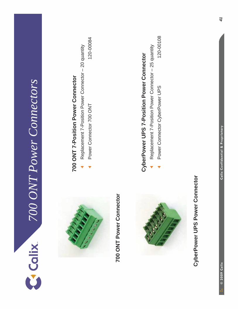
41
700
ON
T Po
wer
Con
nect
ors
700
ON
T 7-
Posi
tion
Pow
er C
onne
ctor
R
epla
cem
ent 7
-Pos
ition
Pow
er C
onne
ctor
–20
qua
ntity
Pow
er C
onne
ctor
700
ON
T12
0-00
084
Cyb
erPo
wer
UPS
7-P
ositi
on P
ower
Con
nect
orR
epla
cem
ent 7
-Pos
ition
Pow
er C
onne
ctor
–25
qua
ntity
Pow
er C
onne
ctor
Cyb
erP
ower
UP
S12
0-00
108
Cyb
erPo
wer
UPS
Pow
er C
onne
ctor
700
ON
T Po
wer
Con
nect
or

42
760
ON
T Po
wer
Con
nect
or
760
ON
T 7-
Posi
tion
Pow
er C
onne
ctor
R
epla
cem
ent 7
-Pos
ition
Pow
er C
onne
ctor
–20
qua
ntity
Pow
er C
onne
ctor
760
ON
T12
0-00
130
760
ON
T Po
wer
Con
nect
or
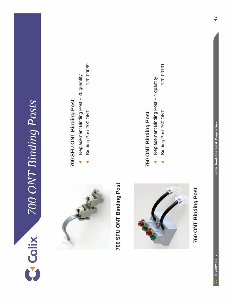
43
700
ON
T Bi
ndin
g Po
sts
700
SFU
ON
T B
indi
ng P
ost
Rep
lace
men
t Bin
ding
Pos
t –20
qua
ntity
Bin
ding
Pos
t 700
ON
T:
120-
0008
9
700
SFU
ON
T B
indi
ng P
ost
760
ON
T B
indi
ng P
ost
Rep
lace
men
t Bin
ding
Pos
t –4
quan
tity
Bin
ding
Pos
t 760
ON
T:
120-
0013
1
760
ON
T B
indi
ng P
ost
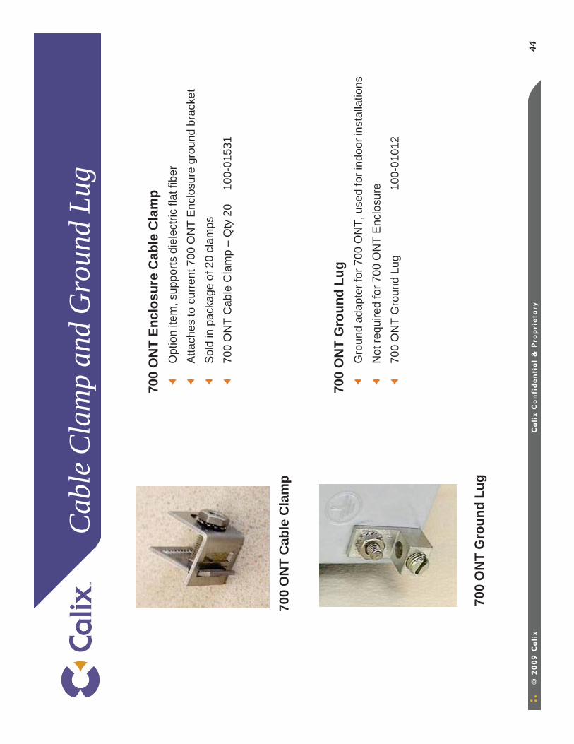
44
Cab
le C
lam
p an
d G
roun
d Lu
g
700
ON
T En
clos
ure
Cab
le C
lam
pO
ptio
n ite
m, s
uppo
rts d
iele
ctric
flat
fibe
rA
ttach
es to
cur
rent
700
ON
T E
nclo
sure
gro
und
brac
ket
Sol
d in
pac
kage
of 2
0 cl
amps
700
ON
T C
able
Cla
mp
–Q
ty 2
010
0-01
531
700
ON
T G
roun
d Lu
gG
roun
d ad
apte
r for
700
ON
T, u
sed
for i
ndoo
r ins
talla
tions
Not
requ
ired
for 7
00 O
NT
Enc
losu
re70
0 O
NT
Gro
und
Lug
100-
0101
2
700
ON
T G
roun
d Lu
g
700
ON
T C
able
Cla
mp
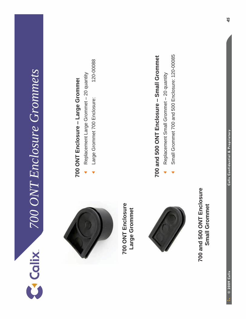
45
700
ON
T En
clos
ure
Gro
mm
ets
700
ON
T En
clos
ure –
Larg
e G
rom
met
R
epla
cem
ent L
arge
Gro
mm
et –
20 q
uant
ityLa
rge
Gro
mm
et 7
00 E
nclo
sure
:12
0-00
088
700
and
500
ON
T En
clos
ure –
Smal
l Gro
mm
etR
epla
cem
ent S
mal
l Gro
mm
et –
20 q
uant
ityS
mal
l Gro
mm
et 7
00 a
nd 5
00 E
nclo
sure
: 120
-000
85
700
and
500
ON
T En
clos
ure
Smal
l Gro
mm
et
700
ON
T En
clos
ure
Larg
e G
rom
met

Than
k yo
u
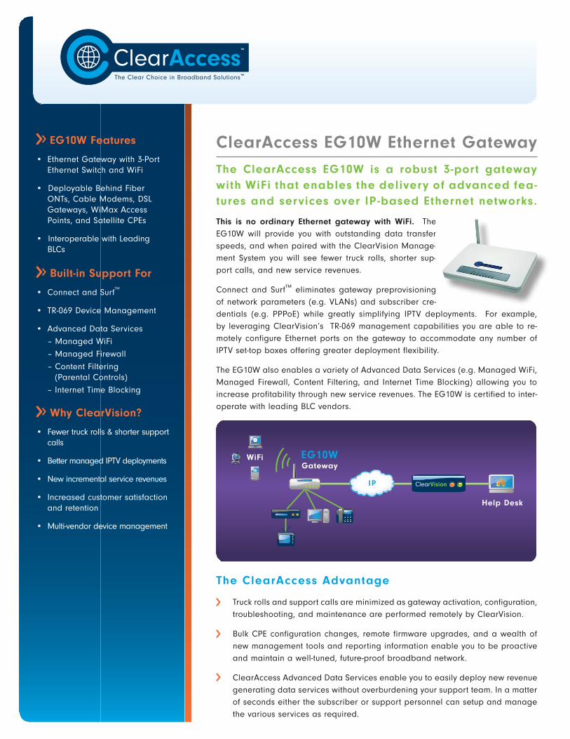
EG10W Features
• Ethernet Gateway with 3-Port Ethernet Switch and WiFi
• Deployable Behind Fiber ONTs, Cable Modems, DSL Gateways, WiMax Access Points, and Satellite CPEs
• Interoperable with Leading BLCs
Built-in Support For
• Connect and SurfTM
• TR-069 Device Management
• Advanced Data Services
– Managed WiFi
– Managed Firewall
– Content Filtering (Parental Controls)
– Internet Time Blocking
Why ClearVision?
• Fewer truck rolls & shorter support calls
• Better managed IPTV deployments
• New incremental service revenues
• Increased customer satisfaction and retention
• Multi-vendor device management
ClearAccess EG10W Ethernet GatewayThe ClearAccess EG10W is a robust 3-port gateway with WiFi that enables the delivery of advanced fea-tures and services over IP -based Ethernet networks.
This is no ordinary Ethernet gateway with WiFi. The EG10W will provide you with outstanding data transfer speeds, and when paired with the ClearVision Manage-ment System you will see fewer truck rolls, shorter sup-port calls, and new service revenues.
Connect and Surf™ eliminates gateway preprovisioning of network parameters (e.g. VLANs) and subscriber cre-dentials (e.g. PPPoE) while greatly simplifying IPTV deployments. For example, by leveraging ClearVision’s TR-069 management capabilities you are able to re-motely configure Ethernet ports on the gateway to accommodate any number of IPTV set-top boxes offering greater deployment flexibility.
The EG10W also enables a variety of Advanced Data Services (e.g. Managed WiFi, Managed Firewall, Content Filtering, and Internet Time Blocking) allowing you to increase profitability through new service revenues. The EG10W is certified to inter-operate with leading BLC vendors.
The ClearAccess Advantage
Truck rolls and support calls are minimized as gateway activation, configuration, troubleshooting, and maintenance are performed remotely by ClearVision.
Bulk CPE configuration changes, remote firmware upgrades, and a wealth of new management tools and reporting information enable you to be proactive and maintain a well-tuned, future-proof broadband network.
ClearAccess Advanced Data Services enable you to easily deploy new revenue generating data services without overburdening your support team. In a matter of seconds either the subscriber or support personnel can setup and manage the various services as required.
ClearVisionIP
WiFi
Help Desk
EG10WGateway

WORLDWIDE SALES
+1 (360) 859 1780
TECHNICAL SUPPORT
+1 (360) 859 1785
1301 NE 144th St., Ste. 119Vancouver, WA 98685 USA
MAIN PHONE
+1 (360) 859 1780
MAIN FAX
+1 (360) 576 2980
www.clearaccess.com
TM
Routing Features
RIP1 (RFC 1058), RIP2 (RFC 1389) and Static Routing
NAT, NAPT and Extensive ALG Support
DHCP Client and Server
DNS Relay
IGMP Proxy
DMZ Host Support
Port Forwarding and Triggering
SIP Traversal
IPSec Tunneling
VPN Support
Dynamic DNS
Physical Specifications
Dims (in): 6.7 (w) x 5.3 (l) x 1.6 (h)
Dims (mm): 170 (w) x 135 (l) x 40 (h)
Environment Operating Temp:
0°C to 40°C
Humidity: 10% - 95% (non-condensing)
Security
Stateful Packet Inspection Firewall
Configurable Firewall Function
Local and Trusted Certificate Verification
IP/URL/Port/MAC Filtering
Supports PAP and CHAP with PPP (RFC 1334)
WAN Protocols
Direct IP (Static)
Direct IP (DHCP)
PPPoE (RFC 2516)
Wireless LAN
802.11b/g wireless access point
Encryption: WEP, WPA-PSK, WPA2, WPA2-PSK, Mixed WPA2/WPA-PSK
MAC addressed-based access control
Modulation: DSSS (b); OFDM (g)
Channels: 11 (US/Can), 13 (ETSI)
Wireless Distibution System (WDS)
Output Power: > 15dBm
Remote Management
TR-069 Device Management
TR-098 Gateway Device Model
TR-106 Generic Device Model
TR-111 LAN Device Management
Automatic Subscriber Activation
Real-time Status and Reporting
Firmware Flash, Restore, and Upgrade
SNMP, Telnet, HTTP, FTP and TFTP
Configuration Backup and Restore
On-demand, Value-added Service
Provisioning (e.g. VoIP, IPTV, etc.)
Physical Interfaces
One (1) Ethernet WAN port (RJ-45)
Three (3) 10/100 Ethernet LAN Ports (RJ-45) with Auto-detection
One (1) External Antenna
Built-in Wall Mounting Keyholes


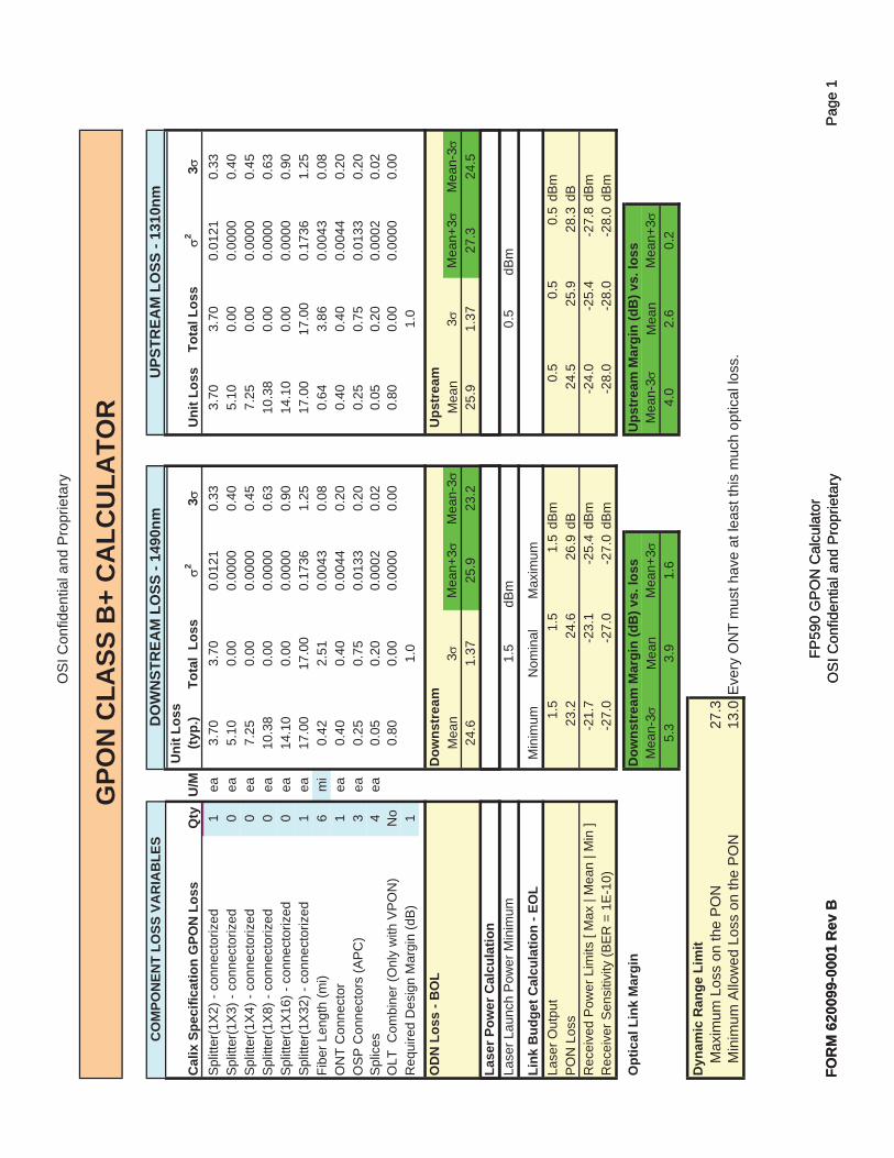
OS
I Con
fiden
tial a
nd P
ropr
ieta
ry
Cal
ix S
peci
ficat
ion
GPO
N L
oss
Qty
U/M
Uni
t Los
s (ty
p.)
Tota
l Lo
ss2
3U
nit L
oss
Tota
l Los
s2
3S
plitt
er(1
X2)
- co
nnec
toriz
ed1
ea3.
703.
700.
0121
0.33
3.70
3.70
0.01
210.
33S
plitt
er(1
X3)
- co
nnec
toriz
ed0
ea5.
100.
000.
0000
0.40
5.10
0.00
0.00
000.
40S
plitt
er(1
X4)
- co
nnec
toriz
ed0
ea7.
250.
000.
0000
0.45
7.25
0.00
0.00
000.
45S
plitt
er(1
X8)
- co
nnec
toriz
ed0
ea10
.38
0.00
0.00
000.
6310
.38
0.00
0.00
000.
63S
plitt
er(1
X16
) - c
onne
ctor
ized
0ea
14.1
00.
000.
0000
0.90
14.1
00.
000.
0000
0.90
Spl
itter
(1X
32) -
con
nect
oriz
ed1
ea17
.00
17.0
00.
1736
1.25
17.0
017
.00
0.17
361.
25Fi
ber L
engt
h (m
i)6
mi
0.42
2.51
0.00
430.
080.
643.
860.
0043
0.08
ON
T C
onne
ctor
1ea
0.40
0.40
0.00
440.
200.
400.
400.
0044
0.20
OS
P C
onne
ctor
s (A
PC
)3
ea0.
250.
750.
0133
0.20
0.25
0.75
0.01
330.
20S
plic
es4
ea0.
050.
200.
0002
0.02
0.05
0.20
0.00
020.
02O
LT C
ombi
ner (
Onl
y w
ith V
PO
N)
No
0.80
0.00
0.00
000.
000.
800.
000.
0000
0.00
Req
uire
d D
esig
n M
argi
n (d
B)
11.
0
1.0
OD
N L
oss
- BO
LD
owns
trea
mU
pstr
eam
Mea
n3
Mea
n+3
Mea
n-3
Mea
n3
Mea
n+3
Mea
n-3
24.6
1.37
25.9
23.2
25.9
1.37
27.3
24.5
Lase
r Pow
er C
alcu
latio
n
GPO
N C
LASS
B+
CA
LCU
LATO
RU
PSTR
EAM
LO
SS -
1310
nmD
OW
NST
REA
M L
OSS
- 14
90nm
CO
MPO
NEN
T LO
SS V
AR
IAB
LES
FOR
M 6
2009
9-00
01 R
ev B
FP59
0 G
PO
N C
alcu
lato
rO
SI C
onfid
entia
l and
Pro
prie
tary
Pag
e 1
Lase
r Lau
nch
Pow
er M
inim
um1.
5dB
m0.
5dB
m
Link
Bud
get C
alcu
latio
n - E
OL
Min
imum
Nom
inal
Max
imum
Lase
r Out
put
1.5
1.5
1.5
dBm
0.5
0.5
0.5
dBm
PO
N L
oss
23.2
24.6
26.9
dB24
.525
.928
.3dB
Rec
eive
d P
ower
Lim
its [
Max
| M
ean
| Min
]-2
1.7
-23.
1-2
5.4
dBm
-24.
0-2
5.4
-27.
8dB
mR
ecei
ver S
ensi
tivity
(BE
R =
1E
-10)
-27.
0-2
7.0
-27.
0dB
m-2
8.0
-28.
0-2
8.0
dBm
Opt
ical
Lin
k M
argi
nD
owns
trea
m M
argi
n (d
B) v
s. lo
ssU
pstr
eam
Mar
gin
(dB
) vs.
loss
Mea
n-3
Mea
nM
ean+
3M
ean-
3M
ean
Mea
n+3
5.3
3.9
1.6
4.0
2.6
0.2
Dyn
amic
Ran
ge L
imit
Max
imum
Los
s on
the
PO
N27
.3M
inim
um A
llow
ed L
oss
on th
e P
ON
13.0
Eve
ry O
NT
mus
t hav
e at
leas
t thi
s m
uch
optic
al lo
ss.
FOR
M 6
2009
9-00
01 R
ev B
FP59
0 G
PO
N C
alcu
lato
rO
SI C
onfid
entia
l and
Pro
prie
tary
Pag
e 1
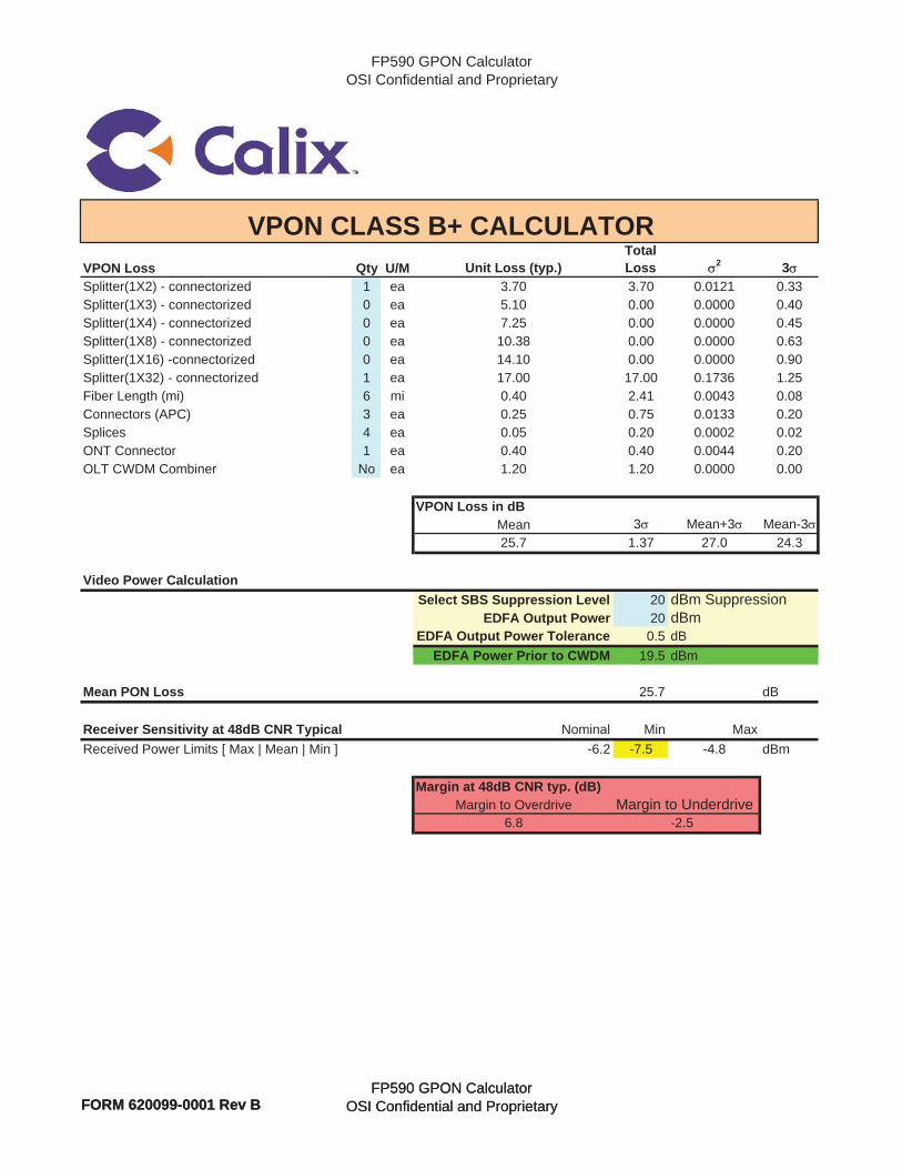
FP590 GPON CalculatorOSI Confidential and Proprietary
VPON Loss Qty U/M Unit Loss (typ.)TotalLoss 2 3
Splitter(1X2) - connectorized 1 ea 3.70 3.70 0.0121 0.33Splitter(1X3) - connectorized 0 ea 5.10 0.00 0.0000 0.40Splitter(1X4) - connectorized 0 ea 7.25 0.00 0.0000 0.45Splitter(1X8) - connectorized 0 ea 10.38 0.00 0.0000 0.63Splitter(1X16) -connectorized 0 ea 14.10 0.00 0.0000 0.90Splitter(1X32) - connectorized 1 ea 17.00 17.00 0.1736 1.25Fiber Length (mi) 6 mi 0.40 2.41 0.0043 0.08Connectors (APC) 3 ea 0.25 0.75 0.0133 0.20Splices 4 ea 0.05 0.20 0.0002 0.02ONT Connector 1 ea 0.40 0.40 0.0044 0.20OLT CWDM Combiner No ea 1.20 1.20 0.0000 0.00
VPON Loss in dBMean 3 Mean+3 Mean-325.7 1.37 27.0 24.3
Video Power CalculationSelect SBS Suppression Level 20 dBm Suppression
EDFA Output Power 20 dBmEDFA Output Power Tolerance 0.5 dB
EDFA Power Prior to CWDM 19 5 dBm
VPON CLASS B+ CALCULATOR
FORM 620099-0001 Rev BFP590 GPON Calculator
OSI Confidential and Proprietary
EDFA Power Prior to CWDM 19.5 dBm
Mean PON Loss 25.7 dB
Receiver Sensitivity at 48dB CNR Typical Nominal Min MaxReceived Power Limits [ Max | Mean | Min ] -6.2 -7.5 -4.8 dBm
Margin at 48dB CNR typ. (dB)Margin to Overdrive Margin to Underdrive
6.8 -2.5
FORM 620099-0001 Rev BFP590 GPON Calculator
OSI Confidential and Proprietary
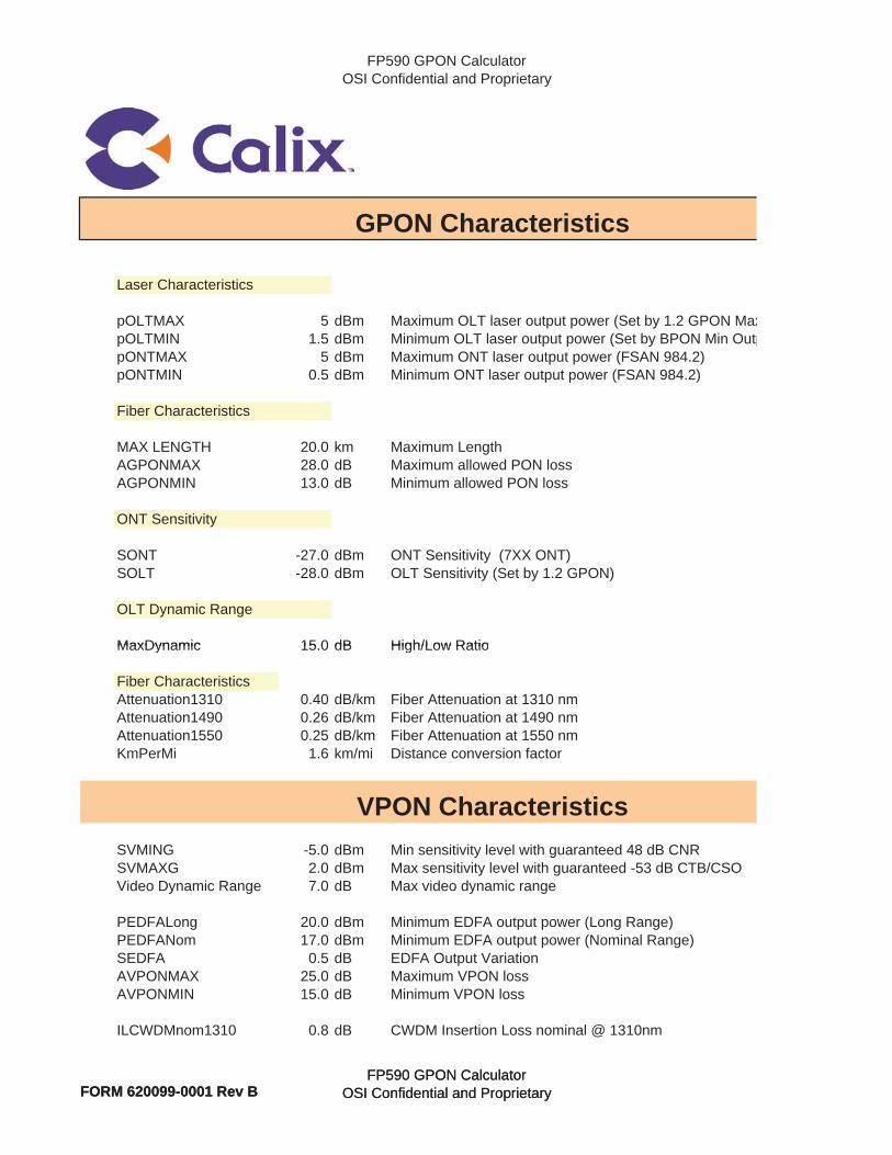
FP590 GPON CalculatorOSI Confidential and Proprietary
Laser Characteristics
pOLTMAX 5 dBm Maximum OLT laser output power (Set by 1.2 GPON MaxpOLTMIN 1.5 dBm Minimum OLT laser output power (Set by BPON Min OutppONTMAX 5 dBm Maximum ONT laser output power (FSAN 984.2)pONTMIN 0.5 dBm Minimum ONT laser output power (FSAN 984.2)
Fiber Characteristics
MAX LENGTH 20.0 km Maximum LengthAGPONMAX 28.0 dB Maximum allowed PON lossAGPONMIN 13.0 dB Minimum allowed PON loss
ONT Sensitivity
SONT -27.0 dBm ONT Sensitivity (7XX ONT)SOLT -28.0 dBm OLT Sensitivity (Set by 1.2 GPON)
OLT Dynamic Range
MaxDynamic 15 0 dB High/Low Ratio
GPON Characteristics
FORM 620099-0001 Rev BFP590 GPON Calculator
OSI Confidential and Proprietary
MaxDynamic 15.0 dB High/Low Ratio
Fiber CharacteristicsAttenuation1310 0.40 dB/km Fiber Attenuation at 1310 nmAttenuation1490 0.26 dB/km Fiber Attenuation at 1490 nmAttenuation1550 0.25 dB/km Fiber Attenuation at 1550 nmKmPerMi 1.6 km/mi Distance conversion factor
SVMING -5.0 dBm Min sensitivity level with guaranteed 48 dB CNRSVMAXG 2.0 dBm Max sensitivity level with guaranteed -53 dB CTB/CSOVideo Dynamic Range 7.0 dB Max video dynamic range
PEDFALong 20.0 dBm Minimum EDFA output power (Long Range)PEDFANom 17.0 dBm Minimum EDFA output power (Nominal Range)SEDFA 0.5 dB EDFA Output VariationAVPONMAX 25.0 dB Maximum VPON lossAVPONMIN 15.0 dB Minimum VPON loss
ILCWDMnom1310 0.8 dB CWDM Insertion Loss nominal @ 1310nm
VPON Characteristics
FORM 620099-0001 Rev BFP590 GPON Calculator
OSI Confidential and Proprietary

FP590 GPON CalculatorOSI Confidential and Proprietary
ILCWDMsig1310 0.0 dB CWDM Insertion Loss sigma @1310nmILCWDMnom1550 1.2 dB CWDM Insertion Loss nominal @ 1550 nmILCWDMsig1550 0.0 dB CWDM Insertion Loss sigma @ 1550 nm
FORM 620099-0001 Rev BFP590 GPON Calculator
OSI Confidential and ProprietaryFORM 620099-0001 Rev BFP590 GPON Calculator
OSI Confidential and Proprietary
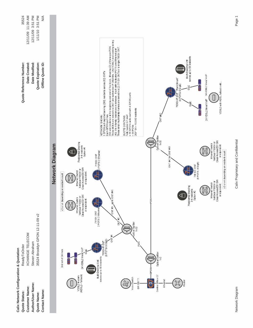
Cal
ix N
etw
ork
Con
figur
atio
n &
Quo
tatio
nQ
uote
Sta
tus:
Rea
dyTo
Ord
erQ
uote
Ref
eren
ce N
umbe
r:35
524
Cus
tom
er N
ame:
XC
HA
NG
E T
ELE
CO
MD
ate
Cre
ated
:12
/11/
09 1
1:39
AM
Aut
hor/U
ser N
ame:
Ste
ven
Abr
aham
Dat
e M
odfie
d:12
/11/
09 3
:51
PM
Quo
te N
ame:
3552
4 B
rook
lyn
GP
ON
12-
11-0
9 v2
Quo
te E
xpira
tion:
1/11
/10
3:5
1 P
MC
onta
ct N
ame:
Offl
ine
Quo
te ID
:N
/A
Net
wor
k D
iagr
am
Net
wor
k D
iagr
amC
alix
Pro
prie
tary
and
Con
fiden
tial
Pag
e 1