Embed Size (px)
Citation preview
Computer Optics and Nanophotonics
Information Technology and Nanotechnology (ITNT-2016) 132
FEASIBILITY STUDY AND MODELING OF
COMPONENTS FOR AN INFORMATIONAL SPACE
SYSTEM BASED ON A LARGE DIFFRACTIVE
MEMBRANE
V.V. Salmin1, S.V. Karpeev
2, K.V. Peresypkin
1, A.S. Сhetverikov
1, I.S. Tkachenko
1
1 Samara National Research University, Samara, Russia 2 Image Processing Systems Institute - Branch of the Federal Scientific Research Centre "Crys-
tallography and Photonics" of Russian Academy of Sciences, Samara, Russia
Abstract. The paper presents a feasibility study for an optical system, based on
a diffractive membrane. The authors have analyzed structural design of diffrac-
tive optical elements for space application and developed finite element models
of diffractive lens’s carrier and mount. The models were developed for two dif-
ferent schemes: MOIRE project and for the original scheme, developed by the
authors. The schemes were analyzed for structural stiffness of the diffractive
lens’s carrier and mount. The shapes and frequencies of natural oscillations of
the carriers of the lens were calculated. The problems of the membrane sys-
tem’s orbit injection and operation were analyzed. An algorithm for the termi-
nal control of the orbital period, eccentricity and longitude of the point of stand-
ing of the orbital surveillance system was proposed.
Keywords: diffractive optics, space membrane optical system, finite element
modeling, space telescope, geostationary orbit
Citation: Salmin VV, Karpeev SV, Peresypkin KV, Сhetverikov AS,
Tkachenko IS. Feasibility study and modeling of components for an informa-
tional space system based on a large diffractive membrane. CEUR Workshop
Proceedings, 2016; 1638: 132-148. DOI: 10.18287/1613-0073-2016-1638-132-
148
Introduction
The problem of high-quality Earth’s surface sensing using spacecraft (SC) is of great
importance. Modern SC, used for remote Earth sensing (RES), utilize big lenses or
mirrors as light-harvesting elements. It leads to a drastic increase in mass and size
characteristics of those SC.
Modern RES SC operate on low orbits, hindering their performance. For example,
they cannot be used to perform continuous shooting. Also, their position might not
allow them to shoot a particular area. In order to perform continuous shooting the
satellite must be delivered to the geostationary orbit (GSO).
Computer Optics and Nanophotonics Salmin VV, Karpeev SV et al…
Information Technology and Nanotechnology (ITNT-2016) 133
Since GSO RES SC require high orbits (about 36000 km), obtaining high-resolution
images requires special optics. Refractive or reflective optics, made of quartz or sitall,
is relatively heavy; therefore, it is problematic to launch new RES SC.
The US Agency for Defense Advanced Research Projects DARPA is working of the
project of a new space telescope with a membrane diffractive optical system. The
project is called MOIRE or Membrane Optical Imager for Real-Time Exploitation [1-
3].
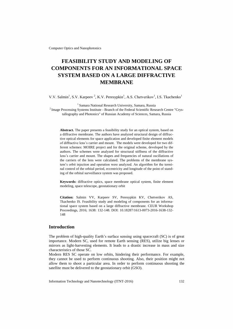
The MOIRE project plans to use a polymer membrane to create optical elements. The
diameter of the entrance pupil will be about 10-20 m (Fig. 1a). Unlike regular lenses
or mirrors, membrane is a diffractive optical element (DOE). Phase bandwidth of a
DOE is formed by microscopic concentric grooves engraved on a plastic surface. The
width of these grooves varies from a few hundred to four micrometers. Optical mem-
branes are much less effective than the traditional optical elements, but, since there
are no more size constraints, the entrance pupil and relative aperture ratio can be in-
creased significantly, while reducing or maintaining SC mass. Membranes will be
mounted on thin metal blades (Fig, 1b), that would fold, forming a SC 6 meters wide.
a)
b)
Fig. 1. Membrane Optical Imager for Real-Time Exploitation project [1-3]
Diffractive optics has a number of advantages over refractive optics on such key pa-
rameters as the weight and size. Aso, it enables simple elements replication in order to
form both spherical and aspherical wavefront sets, making diffractive optic’s elements
useful for different applications. The majority of studies consider diffractive optical
elements either as additional elements for the compensation of aberrations of a refrac-
tive imaging system [4, 5], or as elements for focusing on a particular area [4-14]. For
example, in [6, 7] longitudinal intensity distribution for a coherent case is considered,
[8] considers the process of a plane wave focus using a Fresnel lens, and [9] research-
es methods of compensation of DOE chromatic aberration.
There are considerably less studies on application of diffractive optics towards image
forming. The well-known problem of DOE chromatic aberration hinders its spectrl
range and lowers the image quality in polychromatic light.
The article presents the results of a feasibility study for a space diffractive membrane
optical system (SDMOS), and a study of structural stiffness of SDMOS that performs
remote Earth sensing using membrane diffractive optical elements (DOE).
Computer Optics and Nanophotonics Salmin VV, Karpeev SV et al…
Information Technology and Nanotechnology (ITNT-2016) 134
1 Possibilities of chromatic aberration’s correction in space
telescopes using DOE
Obvious requirements for space telescopes are the correction of chromatic aberrations
and sufficient spatial resolution at a relatively small (a few degrees) angular field.
At first glance, it seems that the diffractive optical elements, due to their extremely
large chromaticity can be of little help in solving the above-mentioned tasks. And
indeed, technoogical constraints on manufacturing high-aperture DOE do not alow
creation of high-aperture diffraction achromatic object lens with required characteris-
tics (which would be an ideal case in terms of size and weight characteristics). Hybrid
diffractive-refractive optical systems attracted attention of researches [5, 15], due to
their ability to effectively correct chromatic aberrations. However, from the point of
utilizing the greatest advantage of diffractive optics – its relative low weight, those
systems are a compromise, since they include big and therefore heavy, refractive ele-
ments.
In case of placing the telescope on a geostationary satellite, the aperture might be
sacrificed due to the possible increase in exposition. However, even in case of low
aperture, creation of purely diffractive optical systems faces problems, since it is im-
possible to correct chromatic aberration by combining collecting diffractive lenses,
distributing the optical power onto several elements. Known approach to correcting
chromatism by combining two purely diffractive lenses with different optical powers
[16] increases the optical powers of the lenses compared with an equivalent single
lens that causes additional technological problems. It is worth noting that a classic
way to deal with chromaticism - a transition to the reflective optics for diffractive
elements is not applicable for obvious reasons. However, conventional optical ele-
ments in the objective lens could be made reflective, therefore removing the chroma-
ticity problem.
Nowadays, the most promising approach is to develop a diffraction mirror imaging
system in which suppression of chromaticity would be done by the imaging system
architecture, as well as modification of the structure of the DOE itself. An example of
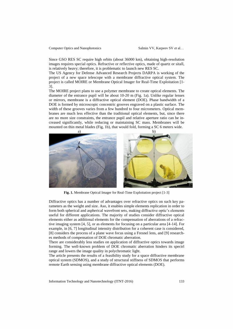
such a system is presented in [17] (Figure 2), that incudes a correcting DOE 3 on top
of the “photonic grid” 1. The correcting DOE 4 is 40 mm in diameter with the focal
distance of 158,5 mm. Focal distance of the lens 2 is 400 mm. Mirrors 4 and 5 are 200
mm in diameter and focal distances 734 and 807.7 mm respectively. The
frequency bandwidth of such a system is about 40 nm.
Fig. 2. The optical scheme of a mirror - diffraction telescope, based on diffractive doublet: 1 –
“photonic grid”, 2 – matching lens, 3 – correcting DOE, 4, 5, - mirrors, 6 – image plane
Computer Optics and Nanophotonics Salmin VV, Karpeev SV et al…
Information Technology and Nanotechnology (ITNT-2016) 135
2 Determining the structural stiffness of the diffractive lens
carrier frame for a MOIRE spacecraft
For the MOIRE project, the structure, that is attaching the lens to the spacecraft (or
the lens carrier), consists of three straight foldable frames. One end of the frames is
connected to the body of the satellite, the other – to the Fresnel lens carrier (Figure 3).
We took this design as a prototype. We model the rods of the frame as a unidirection-
al carbon fiber.
According to the analysis of the diffractive lens’ weight in comparison to the tradi-
tional primary telescope lenses presented in [1-3], in average diffractive lens is about
seven times ligher then a mirror of the same area.
The diffractive lens for the SDMOS is estimated to weight 158.5 kg. The design of
the SDMOS is characterized by the fact that its optical system should receive a fo-
cused and not a plane-parallel lightstream.
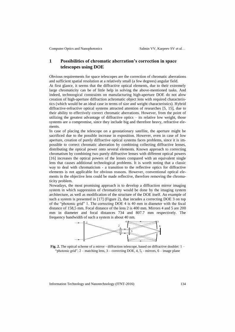
The MOIRE project lens in the unfolded state is a flat frame. This frame is formed by
three concentric rings, connected by radial beams (Figure 3). The perforated mem-
branes, forming the diffractive lens, are stretched on frames, formed by adjacent radi-
al beams and sections of adjacent rings. Radial beams separate the lens onto sections
that are attached to each other pivotally. In the folded state the sections form a bel-
lows shape. During the process of unfolding, sections rotate relatively to each other
until the lens becomes flat. After the unfolding, the pivets get locked.
Fig. 3. Lens structure (D = 10 м; d = 4.96 м; dcp = 7.04 м)
In order to ensure that the lens is not going to deform from reaction with the carrier,
the lens must be attached to it in a statically determinable way. To achieve this, the
carrier frames must be held together by a special structure (the mount) and not the
lens itself. The lens is supposed to be fastened to this mount.
Structure, presented on the Figure 4, corresponds to the published sheme of the
MOIRE project, exept for the special lens mount. This mount is a triangular frame,
the supporting frames are fixed to the tops of the triangle. The lens is fixed to the
middle parts of the frame’s beams. The structure is fixed in the longitudinal and cir-
cumferential extent of freedom and is statically determinable.
Computer Optics and Nanophotonics Salmin VV, Karpeev SV et al…
Information Technology and Nanotechnology (ITNT-2016) 136
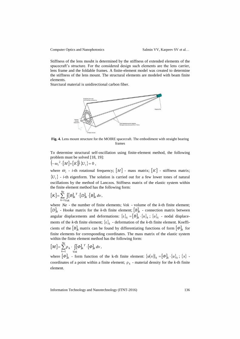
Stiffness of the lens moubt is determined by the stiffness of extended elements of the
spacecraft’s structure. For the considered design such elements are the lens carrier,
lens frame and the foldable frames. A finite-element model was created to determine
the stiffness of the lens mount. The structural elements are modeled with beam finite
elements.
Sturctural material is unidirectional carbon fiber.
Fig. 4. Lens mount structure for the MOIRE spacecraft. The embodiment with straight bearing
frames
To determine structural self-oscillation using finite-element method, the following
problem must be solved [18, 19]:
02
ii UКМ ,
where i - i-th rotational frequency; М - mass matrix; К - stiffness matrix;
iU - i-th eigenform. The solution is carried out for a few lower tones of natural
oscillations by the method of Lanczos. Stiffness matrix of the elastic system within
the finite element method has the following form:
dvBDBK kk
Ne
k Vek
Tk
1
,
where Ne - the number of finite elements; Vek - volume of the k-th finite element;
kD - Hooke matrix for the k-th finite element; kB - connection matrix between
angular displacements and deformations: kkk uB ; ku - nodal displace-
ments of the k-th finite element; k - deformation of the k-th finite element. Koeffi-
cients of the kB matrix can be found by differentiating functions of form kФ for
finite elements for corresponding coordinates. The mass matrix of the elastic system
within the finite element method has the following form:
dvФФM k
Ne
k Vek
Tkk
1
,
where kФ - form function of the k-th finite element: kkk uФxu ; x -
coordinates of a point within a finite element; k - material density for the k-th finite
element.
Computer Optics and Nanophotonics Salmin VV, Karpeev SV et al…
Information Technology and Nanotechnology (ITNT-2016) 137
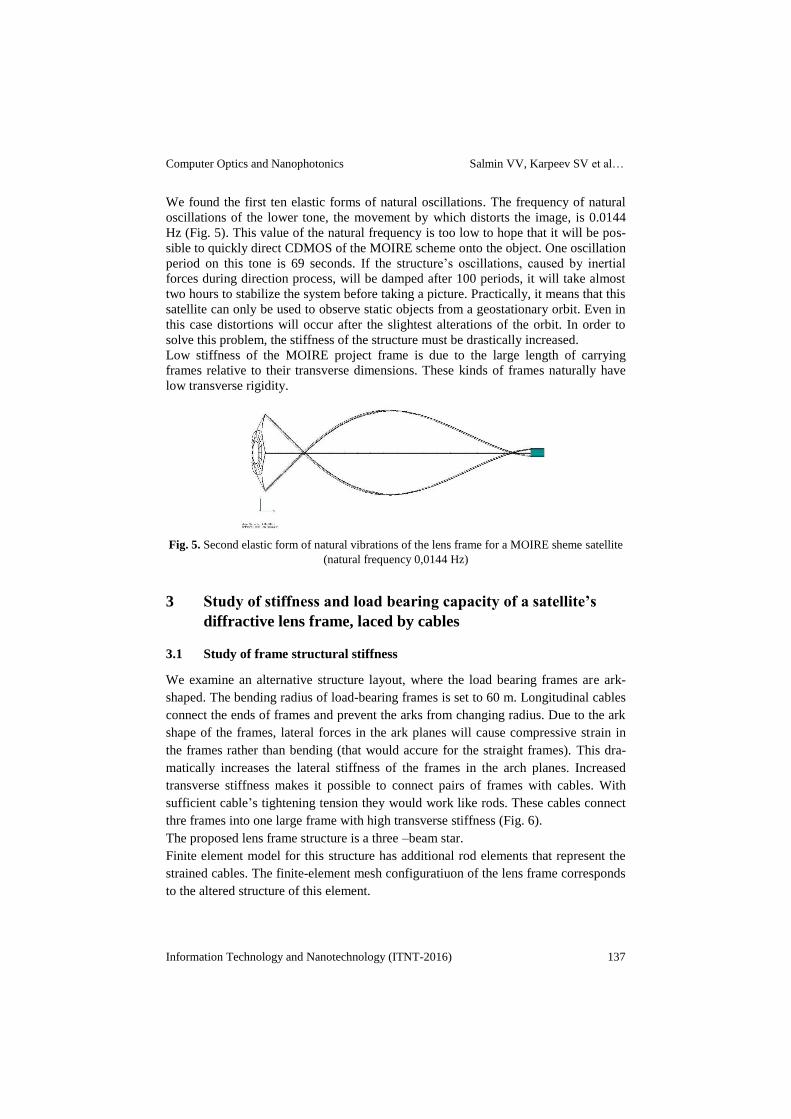
We found the first ten elastic forms of natural oscillations. The frequency of natural
oscillations of the lower tone, the movement by which distorts the image, is 0.0144
Hz (Fig. 5). This value of the natural frequency is too low to hope that it will be pos-
sible to quickly direct CDMOS of the MOIRE scheme onto the object. One oscillation
period on this tone is 69 seconds. If the structure’s oscillations, caused by inertial
forces during direction process, will be damped after 100 periods, it will take almost
two hours to stabilize the system before taking a picture. Practically, it means that this
satellite can only be used to observe static objects from a geostationary orbit. Even in
this case distortions will occur after the slightest alterations of the orbit. In order to
solve this problem, the stiffness of the structure must be drastically increased.
Low stiffness of the MOIRE project frame is due to the large length of carrying
frames relative to their transverse dimensions. These kinds of frames naturally have
low transverse rigidity.
Fig. 5. Second elastic form of natural vibrations of the lens frame for a MOIRE sheme satellite
(natural frequency 0,0144 Hz)
3 Study of stiffness and load bearing capacity of a satellite’s
diffractive lens frame, laced by cables
3.1 Study of frame structural stiffness
We examine an alternative structure layout, where the load bearing frames are ark-
shaped. The bending radius of load-bearing frames is set to 60 m. Longitudinal cables
connect the ends of frames and prevent the arks from changing radius. Due to the ark
shape of the frames, lateral forces in the ark planes will cause compressive strain in
the frames rather than bending (that would accure for the straight frames). This dra-
matically increases the lateral stiffness of the frames in the arch planes. Increased
transverse stiffness makes it possible to connect pairs of frames with cables. With
sufficient cable’s tightening tension they would work like rods. These cables connect
thre frames into one large frame with high transverse stiffness (Fig. 6).
The proposed lens frame structure is a three –beam star.
Finite element model for this structure has additional rod elements that represent the
strained cables. The finite-element mesh configuratiuon of the lens frame corresponds
to the altered structure of this element.
Computer Optics and Nanophotonics Salmin VV, Karpeev SV et al…
Information Technology and Nanotechnology (ITNT-2016) 138
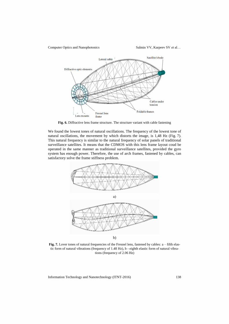
Fig. 6. Diffractive lens frame structure. The structure variant with cable fastening
We found the lowest tones of natural oscillations. The frequency of the lowest tone of
natural oscillations, the movement by which distorts the image, is 1,48 Hz (Fig. 7).
This natural frequency is similar to the natural frequency of solar panels of traditional
surveillance satellites. It means that the CDMOS with this lens frame layout coud be
operated in the same manner as traditional surveillance satellites, provided the gyro
system has enough power. Therefore, the use of arch frames, fastened by cables, can
satisfactory solve the frame stiffness problem.
а)
b)
Fig. 7. Lover tones of natural frequencies of the Fresnel lens, fastened by cables: а – fifth elas-
tic form of natural vibrations (frequency of 1.48 Hz), b - eighth elastic form of natural vibra-
tions (frequency of 2.06 Hz)
Computer Optics and Nanophotonics Salmin VV, Karpeev SV et al…
Information Technology and Nanotechnology (ITNT-2016) 139
3.2 Study of the load-bearing capacity of the lens frame structure
In order for the proposed structural layout to work, the cables must remain strained
during the satellite’s maneuvers. This means that the cable pre-tension must be high-
er than the tension easing from the structure’s deformation during maneuvers. The
finite-element model takes this tension easing into account by addition of compress-
ing forces inside of the rods that represent the cables. In order to determine the cable
pre-tension values, the satellite’s turn must be modeled. Maximum calculated strain-
ing force in the rods would be the desired value of the pre-tension force.
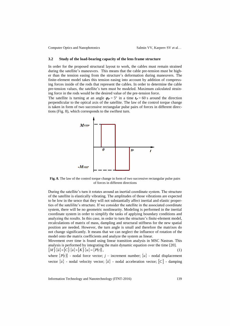
The satellite is turning at an angle Р = 5 in a time tР = 60 s around the direction
perpendicular to the optical axis of the satellite. The law of the control torque change
is taken in form of two successive rectangular pulse pairs of forces in different direc-
tions (Fig. 8), which corresponds to the swiftest turn.
Fig. 8. The law of the control torque change in form of two successive rectangular pulse pairs
of forces in different directions
During the satellite’s turn it rotates around an inertial coordinate system. The structure
of the satellite is elastically vibrating. The amplitudes of those vibrations are expected
to be low in the sence that they will not substantially affect inertial and elastic proper-
ties of the satelilite’s structure. If we consider the satellite in the associated coordinate
system, there will be no geometric nonlinearity. Modeling is performed in the inertial
coordinate system in order to simplify the tasks of applying boundary conditions and
analyzing the results. In this case, in order to turn the structure’s finite-element model,
recalculations of matrix of mass, dampling and structural stiffness for the new spatial
position are needed. However, the turn angle is small and therefore the matrixes do
not change significantly. It means that we can neglect the influence of rotation of the
model onto the matrix coefficients and analyze the system as linear.
Movement over time is found using linear transition analysis in MSC Nastran. This
analysis is performed by integrating the main dynamic equation over the time [20].
tPuKuCuМ , (1)
where tP - nodal force vector; j – increment number; u - nodal displacement
vector u - nodal velocity vector; u - nodal acceleration vector; C - damping
Computer Optics and Nanophotonics Salmin VV, Karpeev SV et al…
Information Technology and Nanotechnology (ITNT-2016) 140
matrix. Speed and acceleration are expressed through movement by the central-
difference approach:
t
uuu
jj
j
2
11
;
t
uuu
jj
j
2
11 ,
where t – time increment. Then, by averaging the vector of nodal forces on three
adjacent steps of integration in time, the system (1) is transformed into:
tAuAuAuA jjj 413211 . (2)
Calculation of the displacement using the system of linear equations (2) carried out
for the initial conditions 0ju и 01 ju , which corresponds to a fixed
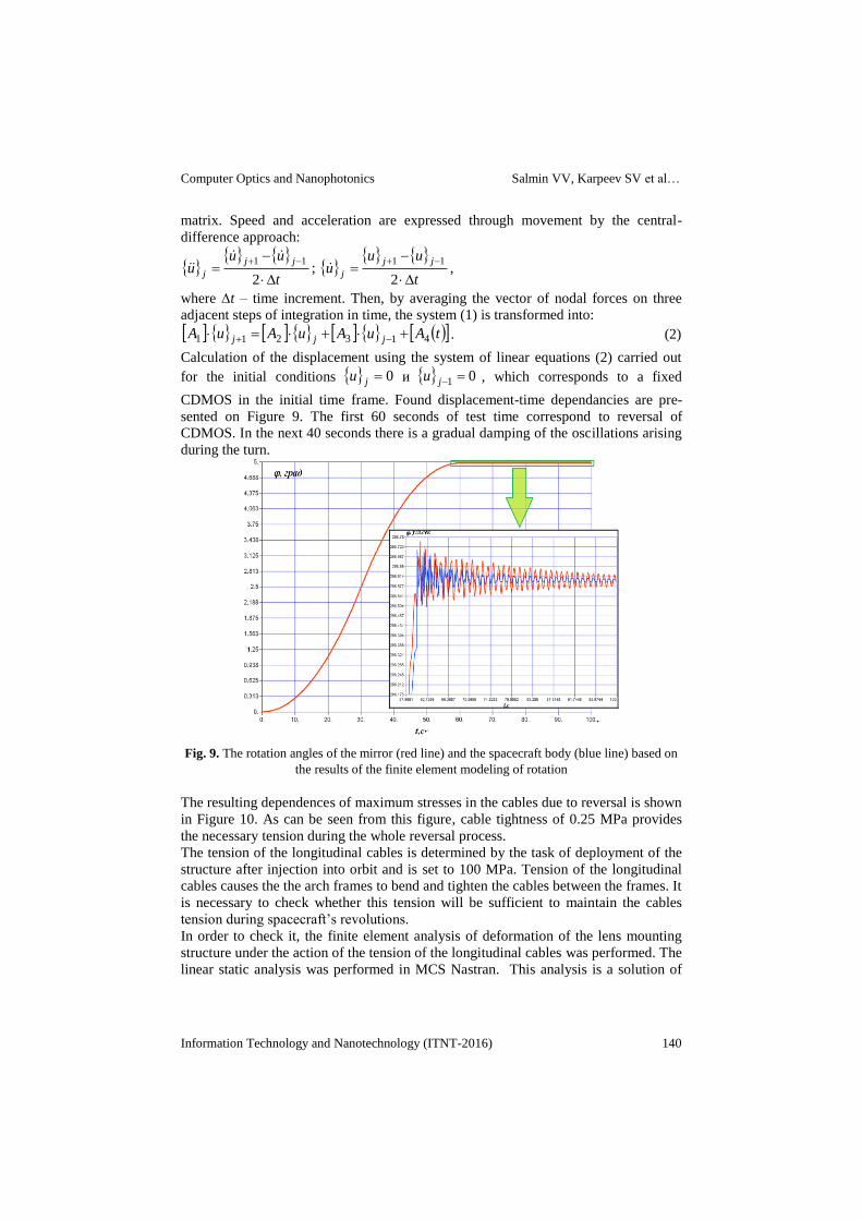
CDMOS in the initial time frame. Found displacement-time dependancies are pre-
sented on Figure 9. The first 60 seconds of test time correspond to reversal of
CDMOS. In the next 40 seconds there is a gradual damping of the oscillations arising
during the turn.
Fig. 9. The rotation angles of the mirror (red line) and the spacecraft body (blue line) based on
the results of the finite element modeling of rotation
The resulting dependences of maximum stresses in the cables due to reversal is shown
in Figure 10. As can be seen from this figure, cable tightness of 0.25 MPa provides
the necessary tension during the whole reversal process.
The tension of the longitudinal cables is determined by the task of deployment of the
structure after injection into orbit and is set to 100 MPa. Tension of the longitudinal
cables causes the the arch frames to bend and tighten the cables between the frames. It
is necessary to check whether this tension will be sufficient to maintain the cables
tension during spacecraft’s revolutions.
In order to check it, the finite element analysis of deformation of the lens mounting
structure under the action of the tension of the longitudinal cables was performed. The
linear static analysis was performed in MCS Nastran. This analysis is a solution of

Computer Optics and Nanophotonics Salmin VV, Karpeev SV et al…
Information Technology and Nanotechnology (ITNT-2016) 141
the linear system of the Hooke's law equations for the considered, with respect to the
vector of nodal displacements u :
PuK .
Fig. 10. Maximal changes in stresss of cables, connecting the frames, depending on the time
Deformation of structure from the effects of tighteing of longitudinal cables is shown
in Figure 11. Figure 12 shows tightness of cables between the arch frames. According
to figure 12, the cable tightness does not exeed 0.85 MPa, which is below the minimal
cable tension during satellite’s maneuvres.
Fig. 11. Structural deformation under the cables tension. The distance between the lens and
body of the spacecraft has decreased by 6.9 mm
Fig. 12. Cables tension between the arch frames. Maximum stress 5,1 MPa, minimum stress
0.85 MPa
-0,3
-0,25
-0,2
-0,15
-0,1
-0,05
0
0,05
0,1
0,15
0,2
0,25
0 10 20 30 40 50 60 70 80 90 100
t, c .
sig
, M
Pa
.
Computer Optics and Nanophotonics Salmin VV, Karpeev SV et al…
Information Technology and Nanotechnology (ITNT-2016) 142
4 CDMOS launch to a geostationary orbit and the correction of
the satellite’s orbit
4.1 Ballistioc sheme of the CDMOS geostationary orbit delivery
CDMOS based on a big diffractive membrane is a large object with low structural
stiffness. During orbit injection of such a system using a chemical booster, significant
overloads may arise, possibly leading to undesirable structural changes of the diffrac-
tive optical system.
In this case, low-thrust electric propulsion engines seem to be better suited for the task
of the CDMOS’s geostationary orbit delivery. Electric propulsion engines create ac-
celerations of about 0,5..1,0 mm /s2. Transportation from a low Earth orbit to the geo-
stationary orbit will take from 100 to 200 days. Weight of a space system, including
tugboat with solar electric propulsion CDMOS will be from 6000 to 8000 kg. Weight
of the surveillance satellite, based on a diffractive membrane, is estimated to be about
3500 kg, the lens itself (including diffractive membranes, frame and mount of the
lens) would weight 500-600 kg. Thus the required thrust of the propulsion system
would be from 2.5 to 4 N and the required power for the electric propulsion engine
would be 50-70 kW.
Ballistic scheme of CDMOS launch to a geostationary orbit includes several steps. On
the first step the orbital system, consisting of folded CDMOS and the space tugboat is
delivered to the low Earth’s orbit by a middle-class rocket “Soyuz” or “Angara”. On
the next stage the payload assist module delivers the system to a higher orbit (500-600
km), where the atmospheric influence is negligeable. On this temporary orbit space
tugboat’s solar panels and the membrane system are unfolded. On the final step of
the orbit injection CDMOS is delivered into the geostationary orbit to the stand point
by the solar space tugboat with an electric propulsion engine.
4.2 Dynamics of the CDMOS’s geostationary orbit delivery
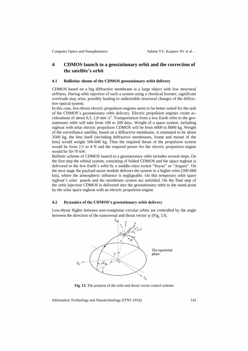
Low-thrust flights between non-complanar circular orbits are controlled by the angle
between the direction of the transversal and thrust vector (Fig. 13).
Fig. 13. The position of the orbit and thrust vector control scheme
Computer Optics and Nanophotonics Salmin VV, Karpeev SV et al…
Information Technology and Nanotechnology (ITNT-2016) 143
Then, the projections of the thrust acceleration on the orbital axis of the coordinate
system are:
sin ,0 ,cosM
Paa
M
Pa WST ,
where P – electric propulsion engine’s thrust, М –current mass.
Additionaly, thrust vector control for flights between non-complanar orbits requires a
change in the sign of the binormal component of reactive acceleration aW twice per
revolution [21].
In [22] a simplified satellite’s low-thrust movement model optimal control of the is
defined as:
usignVuV XmX cos)(),( ,
where
1
0
1)( CV
VBAarctgV X
Xm – the amplitude of the periodic oscil-
lations of the ψ angle;
2sin 00 ii
r
rA K
K
,
2cos 00 ii
r
rB K
K
,
00
rV
,
K
K
K r
rii
r
rC 000
2cos21
,
µ - Earth's gravitational parameter, t
X adtV0
- characteristic velocity, u – argument
of latitude (the phase angle in the orbital motion), r, i - the current values of the aver-
age radius vector of the satellite and the inclination of the orbit.
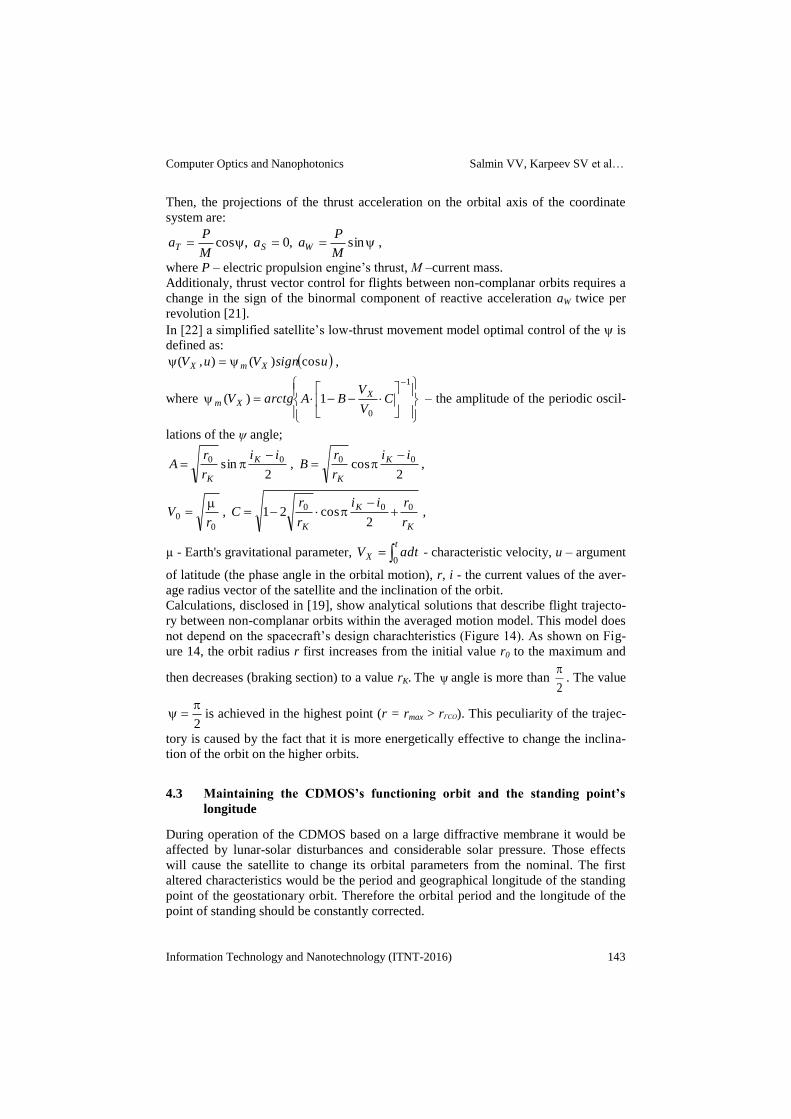
Calculations, disclosed in [19], show analytical solutions that describe flight trajecto-
ry between non-complanar orbits within the averaged motion model. This model does
not depend on the spacecraft’s design charachteristics (Figure 14). As shown on Fig-
ure 14, the orbit radius r first increases from the initial value r0 to the maximum and
then decreases (braking section) to a value rK. The angle is more than 2
. The value
2
is achieved in the highest point (r = rmax > rГСО). This peculiarity of the trajec-
tory is caused by the fact that it is more energetically effective to change the inclina-
tion of the orbit on the higher orbits.
4.3 Maintaining the CDMOS’s functioning orbit and the standing point’s
longitude
During operation of the CDMOS based on a large diffractive membrane it would be
affected by lunar-solar disturbances and considerable solar pressure. Those effects
will cause the satellite to change its orbital parameters from the nominal. The first
altered characteristics would be the period and geographical longitude of the standing
point of the geostationary orbit. Therefore the orbital period and the longitude of the
point of standing should be constantly corrected.
Computer Optics and Nanophotonics Salmin VV, Karpeev SV et al…
Information Technology and Nanotechnology (ITNT-2016) 144
Fig. 14. The change of trajectory parameters and control parameters during flight
(r0 = 7171 km, rK = 42164 km, i0 = 51,60, iK = 00)
The work [23] describes a discrete model of the motion of a geostationary spacecraft
under the influence of small transversal acceleration. Solving of the optimization
problem with the classical dynamic programming method [24] is difficult, because the
discrete movement model is non-linear. Therefore, in [23] the authors propose an
approximate method for solving the problem based on the three-step control algorithm
for circulation period, eccentricity and longitude of the point of standing. Orbit cor-
rection is carried out using low-thrust electric rocket engine that produces acceleration
in the transversal direction.
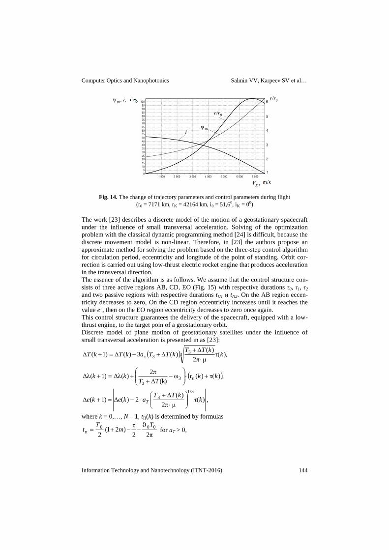
The essence of the algorithm is as follows. We assume that the control structure con-
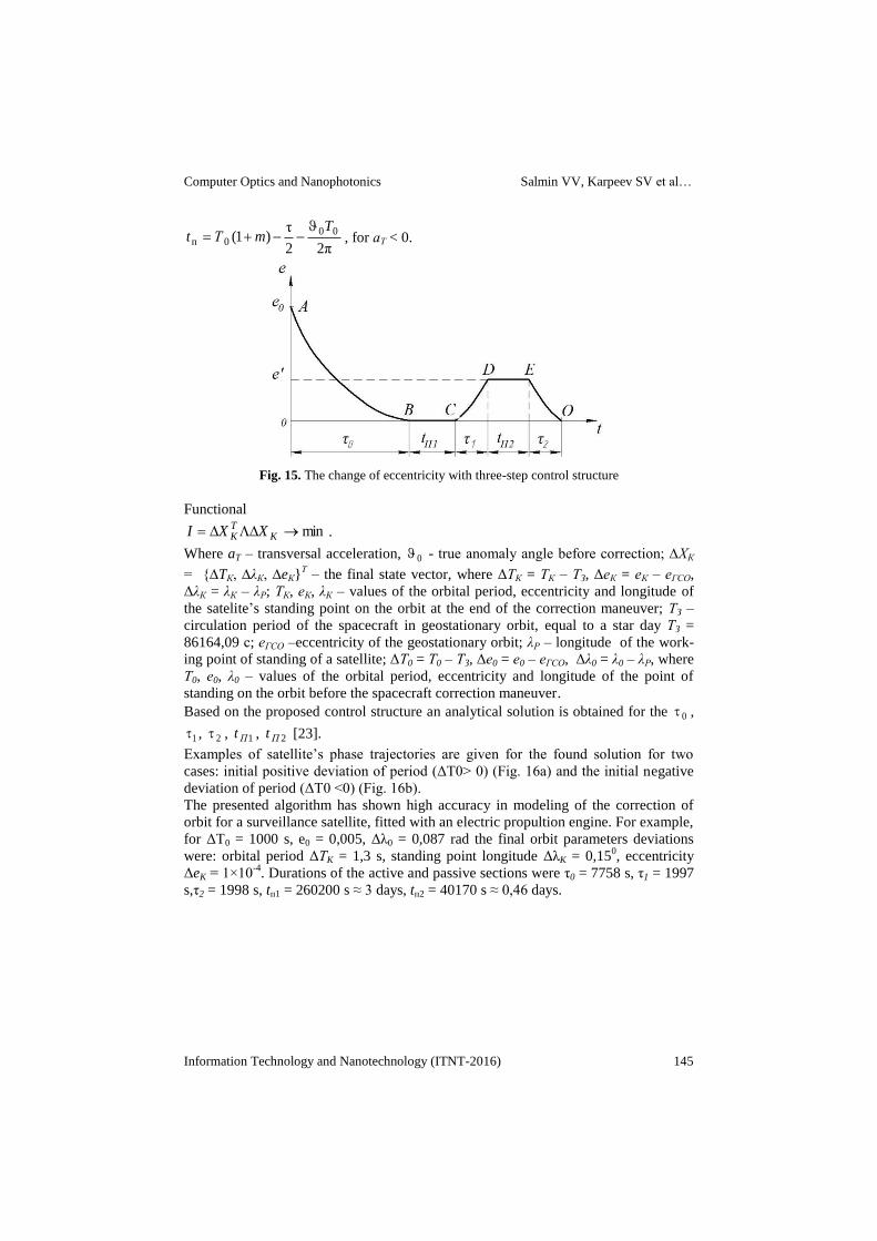
sists of three active regions AB, CD, EO (Fig. 15) with respective durations τ0, τ1, τ2
and two passive regions with respective durations tП1 и tП2. On the AB region eccen-
tricity decreases to zero, On the CD region eccentricity increases until it reaches the
value e’, then on the EO region eccentricity decreases to zero once again.
This control structure guarantees the delivery of the spacecraft, equipped with a low-
thrust engine, to the target poin of a geostationary orbit.
Discrete model of plane motion of geostationary satellites under the influence of
small transversal acceleration is presented in as [23]:
),τ(μ2π
)()(3)(1)( 3
33т k
kTTkTTakTkT
,)τ()(ω(k)Δ
2π)Δλ(1)Δλ( п3
3
kktTT
kk
, )τ(μ2π
)(Δ2)(Δ1)(
1/3
3 kkTТ
akeke T
where k = 0,…, N – 1, tП(k) is determined by formulas
2π2
τ)21(
2
000п
Tm
Тt
for аТ > 0,
Computer Optics and Nanophotonics Salmin VV, Karpeev SV et al…
Information Technology and Nanotechnology (ITNT-2016) 145
2π2
τ)1( 00
0п
TmТt
, for аТ < 0.
Fig. 15. The change of eccentricity with three-step control structure
Functional
min KTK XXI .
Where aT – transversal acceleration, 0 - true anomaly angle before correction; ∆ХК
= {∆TК, ∆λК, ∆eК}Т – the final state vector, where ΔТК = ТК – ТЗ, ΔеК = еК – еГСО,
ΔλК = λК – λР; ТК, еК, λК – values of the orbital period, eccentricity and longitude of
the satelite’s standing point on the orbit at the end of the correction maneuver; ТЗ –
circulation period of the spacecraft in geostationary orbit, equal to a star day ТЗ =
86164,09 с; еГСО –eccentricity of the geostationary orbit; λР – longitude of the work-
ing point of standing of a satellite; ΔТ0 = Т0 – ТЗ, Δе0 = е0 – еГСО, Δλ0 = λ0 – λР, where
Т0, е0, λ0 – values of the orbital period, eccentricity and longitude of the point of
standing on the orbit before the spacecraft correction maneuver.
Based on the proposed control structure an analytical solution is obtained for the 0 ,
1 , 2 , 1Пt , 2Пt [23].
Examples of satellite’s phase trajectories are given for the found solution for two
cases: initial positive deviation of period (ΔT0> 0) (Fig. 16a) and the initial negative
deviation of period (ΔT0 <0) (Fig. 16b).
The presented algorithm has shown high accuracy in modeling of the correction of
orbit for a surveillance satellite, fitted with an electric propultion engine. For example,
for ΔТ0 = 1000 s, e0 = 0,005, Δλ0 = 0,087 rad the final orbit parameters deviations
were: orbital period ΔТK = 1,3 s, standing point longitude ΔλK = 0,150, eccentricity
ΔeK = 1×10⁻⁴
. Durations of the active and passive sections were τ0 = 7758 s, τ1 = 1997
s,τ2 = 1998 s, tп1 = 260200 s ≈ 3 days, tп2 = 40170 s ≈ 0,46 days.

Computer Optics and Nanophotonics Salmin VV, Karpeev SV et al…
Information Technology and Nanotechnology (ITNT-2016) 146
a)
b)
Fig. 16. Examples of satellite’s phase trajectories: а - for ∆T0 > 0, b - for ∆T0 < 0
Conclusion
The feasibility study for a diffractive imaging system has been carried out. Creation
of a purely diffractive optic system currently is practically impossible because of the
difficulty of correcting chromatic aberration of the image. For space-based telescopes,
located on the geostationary orbit, a promising approach is the use of diffraction-
refraction imaging systems, in which the chromaticity suppression would be done by
the imaging system’s architecture, as well as modifications of the structure of the
diffractive optic elements.
A structural finite-element analysis of the space telescope, utilizing diffractive mem-
branes as main elements of the optical system, has been carried out. The analysis was
performed for two schemes – one for the MOIRE prototype and the other for the orig-
inal scheme, proposed by the authors. In the original scheme the frames that hold the
diffractive membrane (10 meters in diameter), are made in the ark forms and laced
with cables. As a result of the analysis, the forms and frequencies of natural oscilla-
tions of the mount of the lens (the frame) were obtained. The frequency of natural
Computer Optics and Nanophotonics Salmin VV, Karpeev SV et al…
Information Technology and Nanotechnology (ITNT-2016) 147
oscillations of the lower tone, movement by which distorts the image, is greater by
two orders of magnitude for the proposed scheme in comparison with the prototype.
The use of arch-shaped frames and cable lacing in structures of CDMOS, using dif-
fractive membranes as main components of the optical system, allows achieving suf-
ficient structural stiffness.
A low-thrust electric propulsion engine is proposed as a preferable means of CDMOS
delivery from the lower orbit to the point of destination on the geostationary orbit.
References
1. Early J, Hyde R, Baron R. Twenty meter space telescope based on diffractive Fresnel lens.
Proceedings of SPIE. The International Society for Optical Engineering, 2004; 5166: 148-
156.
2. Atcheson P, Stewart C, Domber J, Whiteaker K, Cole J, Spuhler P, Seltzer A, Smith L.
MOIRE – Initial demonstration of a transmissive diffractive membrane optic for large
lightweight optical telescopes. Proceedings of SPIE – The International Society for Optical
Engineering, 2012; 8442: 844221.
3. Atcheson P, Domber J, Whiteaker K, Britten JA, Dixit SN, Farmer B. MOIRE – Ground
demonstration of a large aperture diffractive transmissive telescope. Proceedings of SPIE –
The International Society for Optical Engineering, 2014; 9143: 91431W.
4. Greisukh GI, Efimenko IM, Stepanov SА. Principles of creation of projection and focusing
optical systems with diffraction elements. Computer Optics, 1987; 1: 114-116. [In Rus-
sian]
5. Greisukh GI, Ezhov EG, Stepanov SA. Aberration properties and performance of a new
diffractive-gradient-index high-resolution objective. Applied Optics, 2001; 40(16): 2730-
2735.
6. Zapata-Rodrıiguez CJ, Martinez-Corral M, Andres P, Pons A. Axial behavior of diffractive
lenses under Gaussian illumination: complex-argument spectral analysis. J. Opt. Soc. Am.
A, 1999; 16(10): 2532-2538.
7. Khonina SN, Ustinov АV, Skidanov RV. The binary lens: Study of local foci. Computer
Optics, 2011; 35(3): 339-346. [In Russian]
8. Faklis D, Morris GM. Spectral properties of multiorder diffractive lenses. Applied Optics,
1995; 34(14): 2462-2468.
9. Karpeev SV, Аlferov SV, Khonina SN, Kudryashov SI. Investigation of the effect of
broadband radiation intensity distribution formed by a diffractive optical element. Com-
puter Optics, 2014; 38(4): 689-694. [In Russian]
10. Kotlyar VV, Khonina SN, Soifer VA. Diffraction computation of focusator into longitudi-
nal segment and multifocal lens. Proccedings of SPIE, 1993; 1780: 263-272.
11. Soifer VA, Doskolovich LL, Kazanskiy NL. Multifocal diffractive elements. Optical En-
gineering, 1994; 33(11): 3610-3615.
12. Dobson SL, Sun P, Fainman Y. Diffractive lenses for chromatic confocal imaging. Ap-
plied Optics, 1997; 36(20): 4744-4748.
13. Mait JN, Prather DW, Mirotznik MS. Binary subwavelength diffractive lens design. Optics
Letters, 1998; 23(17): 1343-1345.
14. Motogaito A, Hiramatsu K. Fabrication of Binary Diffractive Lenses and the Application
to LED Lighting for Controlling Luminosity Distribution. Optics and Photonics Journal,
2013; 3: 67-73.
Computer Optics and Nanophotonics Salmin VV, Karpeev SV et al…
Information Technology and Nanotechnology (ITNT-2016) 148
15. Greisukh GI, Ezhov EG, Kazin SV, Stepanov SА. Ahromatic diffraction and diffraction-
refraction systems of X-Ray range. Computer Optics, 2011; 35(2): 188-195. [In Russian]
16. Farn MW, Goodman JW. Diffractive doublets corrected at two wavelength. J. Opt. Soc.
Am. A, 1991; 8(6): 860-867.
17. Andersen G, Tullson D. Broadband antihole photon sieve telescope. Applied Optics, 2007;
46(18): 3706-3708.
18. Zenkevich O, Morgan L. Finite elements and approximations. Moscow: Mir, 1986; 318 p.
[In Russian]
19. Zienkiewicz OC, Taylor R. The finite element method. Fifth edition. Butterwoth-
Heinemann, 2000.
20. MSC. Nastran 2004 Reference Manual: Official website of the MSC Corporation. URL:
https://simcompanion.mscsoftware.com/resources/sites/MSC/content/meta/DOCUMENT
ATION/9000/DOC9188/~secure/refman.pdf
21. Grodzovskij GL, Ivanov VА, Tokarev VV. The mechanics of space flight with the low
thrust. Moscow: Nauka, 1966; 704 p. [In Russian]
22. Lebedev VN. Calculation of the low-thrust spacecraft’s motion. Moscow: VTS АS USSR,
1968; 108 p. [In Russian]
23. Salmin VV, Chetverikov AS. Management of flat orbital parameters of the geostationary
spacecraft with a low-thrust engine. Vestnik SSAU, 2015; 14(4): 92-101. [In Russian]
24. Bellman R. Dynamic programming. Moscow: Inostrannaya literatura, 1960; 400 p. [In
Russian]


![BS-1638, BS-1642, BS-1646 - Olympia - Electronicsen]file.pdf · BS-1638, BS-1642, BS-1646 ... The panels offer up to 16 zones and are suitable for large installations such as shopping](https://img.pdfslide.us/doc/110x75/5aa1f3177f8b9a436d8c4f51/bs-1638-bs-1642-bs-1646-olympia-electronics-enfilepdfbs-1638-bs-1642-bs-1646.jpg)


![deriv.nls.uk · [David Calderwood,] ‘Motives and Causes ofHumiHatioun’, c.1638 132 [Archibald Campbell ofGlencarradale,] ‘Report ofthe Glasgow Assembly’, 1638 137 Robert Baillie,‘A](https://img.pdfslide.us/doc/110x75/5ebddf9ec7af780947734d3c/derivnlsuk-david-calderwood-amotives-and-causes-ofhumihatiouna-c1638.jpg)
![Signed Copy [.pdf 1638 KB]](https://img.pdfslide.us/doc/110x75/5868c2141a28ab5e1d8b5cb5/signed-copy-pdf-1638-kb.jpg)