Embed Size (px)
Citation preview

FEASIBILITY STUDIES OF IMPLEMENTATION OF HVDC
DISTRIBUTION NETWORK IN MALAYSIA
CHUA KEN TAT
A project report submitted in partial fulfillment of the requirements for
the award of Master of Engineering (Electrical)
Faculty of Engineering and Science
Universiti Tunku Abdul Rahman
MAY 2017

ii
DECLARATION
I hereby declare that this project report is based on my original work except
for quotations and citations which have been duly acknowledged. I also
declare that it has not been previously or concurrently submitted for any other
degree or award at UTAR or other institutions.
Signature:
Name: Chua Ken Tat
Student ID: 1605113
Date: 11th May 2017

iii
APPROVAL FOR SUBMISSION
I certify that this project report entitled “FEASIBILITY STUDIES OF
IMPLEMENTATION OF HVDC DISTRIBUTION NETWORK IN
MALAYSIA” was prepared by CHUA KEN TAT has met the required
standard for submission in partial fulfillment of the requirements for the award
of Master of Engineering (Electrical) at Universiti Tunku Abdul Rahman.
Approved by,
Signature :
Supervisor: Dr. Chew Kuew Wai
Date :

iv
The copyright of this report belongs to the author under the terms of
the copyright Act 1987 as qualified by Intellectual Property Policy of
Universiti Tunku Abdul Rahman. Due acknowledgement shall always be
made of the use of any material contained in, or derived from, this report.
© 2017, Chua Ken Tat. All right reserved.
v
ACKNOWLEDGEMENTS
I would like to acknowledge and thanks everyone who had contributed to the
successful completion of this project. I would like to take this opportunity to
register my sincere gratitude to my project supervisor, Dr. Chew Kuew Wai
for his invaluable advice, guidance and patience throughout the development
of the project.

vi
ABSTRACT
FEASIBILITY STUDIES OF IMPLEMENTATION OF HVDC
DISTRIBUTION NETWORK IN MALAYSIA
Chua Ken Tat
In early of electric power distribution, direct current (DC) is the main system
for transmitting the power. It was started from the DC generators which
designed by Thomas Edison. The DC system is a mature technology but it
comes with the drawback of high power losses and voltage drops when
transmitting the power through long distances. As technology evolved, the DC
is then replaced by alternating current (AC). AC has been widely used to
transmit the power for last few decades, since the voltage levels can be easily
increased by transformers. Thus, the power losses and voltage drops could be
controlled. However, AC has some limitations such as system unstable,
voltage drop due to impedances of AC lines and synchronization of machine
which can affect the power transmission. In consequence, it brought back with
the use of DC in some power transmission projects. HVDC transmission
system is the first technology which able to transmit large amount of power
through the long distances without losing much power and voltage. Other
advantages such as no reactive power compensation, lower investment cost
and lesser environment impacts have led the HVDC system more attractive in
electric power system. Therefore, a study is carried out to compare and
evaluate the design concept, component, technology, benefit and cost between

vii
HVAC and HVDC transmission systems. The study is also focused on the
evaluation of suitability to implement HVDC transmission system in Malaysia
by investigating the power demand, system configuration, cost and impacts on
environment.

viii
TABLE OF CONTENTS
PAGE
DECLARATION ii
APPROVAL FOR SUBMISSION iii
ACKNOWLEDGEMENTS v
ABSTRACT vi
LIST OF TABLES xi
LIST OF FIGURES xii
LIST OF ABBREVIATIONS/GLOSSARY xv
LIST OF APPENDICES xvi
CHAPTER
1. INTRODUCTION 1 1.1 Background of the Study 1 1.2 Problem Statement and Objectives 3 1.3 Overview of the Project 4
2. LITERATURE REVIEW 6 2.1 HVAC Transmission System 6 2.2 HVDC Transmission System 8 2.3 Components of HVDC Transmission System 9
2.3.1 Converters 10 2.3.2 Smoothing Reactors 10
2.3.3 Harmonice Filters 11
2.3.4 Reactive Power Source 12
2.3.5 Electrodes 13
2.3.6 AC Circuit Breakers 13
2.3.7 Layout of HVDC Transmission System 14 2.4 Types of HVDC Transmission System 14
2.4.1 Back to Back HVDC System 15
2.4.2 Monopolar HVDC System 15 2.4.3 Bipolar HVDC System 16 2.4.4 Multi-terminal HVDC System 17
2.5 Types of Converter 18
2.5.1 Line Commutated Converter (LCC) 18
2.5.2 Voltage Source Converter (VSC) 20
2.5.3 Comparison of HVDC Converters 21 2.6 Comparison of AC and DC Transmissions 22
2.6.1 Advantages of HVDC Transmission System 22
2.6.2 Disadvantages of HVDC Transmission System 24
2.7 Construction of HVDC Transmission System 25
2.7.1 Development of the Staging Area 26
2.7.2 Establish Access 26

ix
2.7.3 Tower Construction 27
2.7.4 Substation Construction 29
2.7.5 Conductor Stringing 30
2.8 Design Features of HVDC Transmission System 30
2.8.1 Route Selection 31
2.8.2 Transmission Line Design 31
2.9 Cost of Transmission System 33
2.9.1 Cost of HVDC Components 34
2.9.1.1 Cost of LCC - HVDC Components 34
2.9.1.2 Cost of VSC - HVDC Components 35
2.9.2 Cost Structure of HVDC Transmission System 36
2.9.3 Cost of HVAC Components 36
2.9.3.1 Cost of Transformers 37
2.9.3.2 Cost of Compensators 37
2.9.3.3 Cost of AC Cable 37
2.9.3.4 Cost of Switchgear 39
2.10 HVDC Transmission System in Malaysia 40
3. METHODOLOGY 42 3.1 Introduction 42
3.2 Background 42
3.2.1 Xiangjiaba - Shanghai HVDC Transmission System 42
3.2.2 Raichur - Solapur HVAC Transmission System 44
3.3 Layout 45
3.3.1 Layout of Xiangjiaba - Shanghai HVDC System 45
3.3.2 Layout of Raichur - Solapur HVAC System 46
3.4 Design Features 48
3.4.1 Design Features of Xiangjiaba - Shanghai HVDC
System 48
3.4.2 Design Features of Raichur - Solapur HVAC System 50
3.5 Main Components 50
3.5.1 The Xiangjiaba - Shanghai HVDC System 50
3.5.1.1 Thyristor Valves 50
3.5.1.2 Converter Transformers 51
3.5.1.3 Smooth Reactors 51
3.5.2 The Raichur - Solapur HVAC Transmission System 51
3.5.2.1 Generators 51
3.5.2.2 Transformers 52
3.5.2.3 Transmission Line 52
3.5.2.4 Bus Bars 52
3.6 Short Circuit Current in HVAC and HVDC Transmissions 52
3.6.1 Simulation of HVAC Transmission System 54
3.6.2 Simulation of HVDC Transmission System 55
4. RESULT AND DISCUSSION 56 4.1 Design Aspects for Transmission Lines 56 4.2 Number of Lines in Parallel 57
x
4.3 Line Losses 58 4.4 Conductor Load on Tower 59
4.5 Comparison between HVDC China and HVAC India 60
4.6 Simulation Results 61
4.6.1 Single Line to Ground Fault 61
4.6.2 Line to Line Fault 62
3.6.1 Fault in Transmission Line 63
4.7 Comparison of Fault Current 64
4.8 Malaysia Conditions 65
5. CONCLUSION AND RECOMMENDATIONS 67
5.1 Conclusion 67
5.2 Recommendations 70
REFERENCES 71
APPENDICES 74 APPENDIX A –Simulation Model of HVAC Transmission System 74 APPENDIX B –Simulation Model of HVDC Transmission System 75
xi
LIST OF TABLES
Table Page
2.1 Comparison of HVDC Converters 21
2.2 DC Cable Cost according to Power Capacity 34
2.3 Cable Cost per km for LCC – HVDC Transmission System 35
2.4 Cable Cost per km for VSC – HVDC Transmission System 35
2.5 Cost of Transformers 37
2.6 Compensation Needed (MVA) at Each End of Each Cable Installed 38
2.7 Cost of Reactive Power Compensators 38
2.8 Cost of Switchgear 39
3.1 Information of Xiangjiaba – Shanghai HVDC System 43
4.1 AC and DC Transmission Lines 56
4.2 Number of Lines required for HVAC and HVDCSystems 57
4.3 Comparison between HVDC China and HVAC India 60
4.4 Fault Current Comparison For HVAC and HVDC Systems 64

xii
LIST OF FIGURES
Figure Page
2.1 Electrical Power System 6
2.2 HVAC Transmission System 7
2.3 Components of AC Substation 8
2.4 Schematic of HVDC Transmission System 9
2.5 HVDC Smoothing Reactor 11
2.6 AC Harmonic Filter Area 12
2.7 AC Circuit Breakers 13
2.8 Layout of HVDC Transmission System 14
2.9 Circuit Diagram of Back to Back HVDC System 15
2.10 Circuit Diagram of Monopolar HVDC System 16
2.11 Circuit Diagram of Bipolar HVDC System 17
2.12 Circuit Diagram of Multi-terminal HVDC System 18
2.13 LCC - HVDC System 19
2.14 VSC - HVDC System 20
2.15 Three Conductors AC Tower versus Two Conductors DC Tower 22
2.16 AC Transmission Tower versur DC Transmission Tower 23
2.17 Site Prepraration for Construction 27
2.18 Stones being drilled to make the tower foundation footings 27
2.19 Anchor bolts cage is prepared to strengthen the tower 28
2.20 Anchor bolts cage is installed 28
2.21 Another hole being drilled for tower footing 28

xiii
2.22 The components of tower are moved by uinsg helicopter 29
2.23 A crane being used to build the tower 29
2.24 Substation under Construction 30
2.25 Typical Power Transmission Towers: Lattice Type, Monopole 32
2.26 Cost of HVAC and HVDC Transmission Lines 33
2.27 Cost Structure of HVDC Transmission System 36
2.28 Monopolar HVDC System betweem Malaysia and Thailand 41
2.29 The Thailand - Malaysia Interconnection HVDC System 41
3.1 The Xiangjiaba - Shanghai HVDC Transmission System 44
3.2 The Raichur - Solapur HVAC Transmission System 45
3.3 Power System Layout for Xiangjiaba - Shanghai HVDC 46
3.4 Power System Layout for Raichur - Solapur HVAC 48
3.5 Bipolar Station Layout with Two 400 kV Converters in Series 49
3.6 High Tension Insulator 50
3.7 Simulation Model of HVAC Transmission System 54
3.8 Simulation Model of HVDC Transmission System 55
4.1 Transmission Lines for 800 kV AC and 500 kV DC 57
4.2 RoW for 800 kV HVDC and 765 kV HVAC Transmission Towers 58
4.3 Power Losses on AC and DC Lines 59
4.4 Total Conductor Load on AC and DC Towers 59
4.5 Single Line to Ground Fault Current for HVAC System 61
4.6 Single Line to Ground Fault Current for HVDC System 61
4.7 Line to Line Fault Current for HVAC System 62
4.8 Line to Line Fault Current for HVDC System 62
4.9 Fault Current at Transmission Line for HVAC System 63

xiv
4.10 Fault Current at Transmission Line for HVDC System 63

xv
LIST OF ABBREVIATIONS / GLOSSARY
DC Direct Current
AC Alternating Current
HVAC High Voltage Alternating Current
EHVAC Extra High Voltage Alternating Current
HPO High Phase Order
HVDC High Voltage Direct Current
CB Circuit Breaker
LCC Line Commutated Converter
VSC Voltage Source Converter
TNB Tenaga Nasional Berhad
EGAT Electricity Generating Authority of Thailand
SGCC State Grid Corporation of China
RoW Right of Way
EMF Electric Magnetic Field
MI Mass Impregnated

xvi
LIST OF APPENDICES
Appendix Title Page
A Simulation Model of HVAC Transmission System 74
B Simulation Model of HVDC Transmission System 75

1
CHAPTER 1
INTRODUCTION
1.1 Background of the Study
In a country, energy plays a major role for an economic growth
without suffering the poorness. Natural energy resources such as oil, coil,
natural gas, wind, solar and hydropower can be used to generate the electric
power. These resources generally occur in faraway from the cities. Hence,
high voltage transmission lines (HVTLs) have been found to efficiently
transmit the electric power over the long distances from generation station to
consumer. The electric power transmission systems are categorized into high
voltage alternating current (HVAC), extra high voltage alternating current
(EHVAC), high phase order (HPO) HVAC, high voltage direct current
(HVDC) and composite AC/DC transmission lines.
Traditionally, generation, transmission and distribution are the
activities that concerned in the electric power system. The generation activity
mainly used to generate or convert the energy resources into electric power. In
transmission activity, the electric power is transmitted from generation station
to distribution station. Then, distribution activity is focused on distributing the
electric power to consumers. In the beginning, the generation, transmission

2
and distribution of electric power are carried out in direct current (DC)
waveform. The first electric power transmission line is developed by DC. The
fundamental concept of Volt, Ohm, Ampere, Galvani and Oersted have been
discovered in the DC field. Thomas Edison (1857 – 1931) designed and built
the world first electric central station (DC) in the Pearl Street, New York on
1882. Even though there is the existence of the first rise of DC, then DC is
replaced by alternating current (AC) for better uses. This is due to the supply
of electric devices such as transformer, induction motor and polyphase circuits
on 1890. The transformer is extremely easy and simple to vary the voltage
level for the transmission and the induction motor that worked solely with AC
in the industries. Thus, AC has becomes very helpful for industrial and
residential areas. However for long transmission distances, AC has some
limits which led to use the DC in the power transmission projects. HVAC has
becomes the strong technology of power transmission system for the last few
decades. With increasing demand for power, the importance of HVAC is
lesser as compared to HVDC. This is because of the limitation on reactive
power, AC cable lines are not suitable for long distances which can cause the
transmission system suffered with higher power losses. But HVDC does not
have this issue, it is designed to transmit large amount of electric power
through the long distances with low power losses. Each conductor of HVDC
able to transfer more power than HVAC. Therefore, the profile of pylons and
wiring are reduced, both money and land are saved. HVDC also can apply
with different frequency between grid systems in order to improve the stability
and reliability of system. From these, it is clear that HVDC is more favorable
than HVAC due to its technical, economical and benefit of environmental.

3
In this project, a comparative study is carried out for HVAC and
HVDC transmission systems. This study is to evaluate and compare the design
concept, component, technology, benefit and cost between HVAC and HVDC
transmission systems. Moreover, this project is focused on evaluation of
suitability to implement HVDC transmission system in Malaysia by
investigating the power demand, system configuration, cost and impacts on
environment.
1.2 Problem Statement and Objectives
Early electric power distribution, the AC generators are located near in
the industrial and residential areas. As electric power demand is increasing,
the distances between loads and generation station is increased. A long AC
transmission line connected with a generator may cause the power system
unstable and higher power losses. Thus, the main challenge of transmission is
presented to transmit the power over long distances.
With retentive evolution of HVDC technology, HVDC has more
effectual to transmit the electric power with low power losses over the long
distances. It has been widely used for bulk power transmission on last 40 years.
The HVDC transmission system able to improve the system stability and
reliability. More advantages such as no reactive power compensation required,
able to connect two asynchronous grids, using less land and lower capital cost
have make the HVDC became a strong and reliable backbone structure in

4
electric power supply. From this, HVDC transmission system has more
advantages than HVAC transmission system.
In Malaysia, the growth of economy is remained favorable. Strong
domestic economic fundamentals have allowed the economy to grow. With
the strong growth in economy, the demand of electric power will be increased.
Tenaga Nasional Berhad (TNB) is the local company that supplies the electric
power to consumers. As the power demand is increased, a new and longer
transmission lines need to be constructed. Hence, high efficient technology
such as HVDC transmission system able to fulfill the power demand.
The objectives of this project are:
1. To evaluate HVAC and HVDC transmission systems.
2. To investigate the system configuration, technical consideration,
environmental impact and transmission cost for both HVAC and
HVDC.
3. To determine the suitability to implement HVDC transmission system
in Malaysia.
1.3 Overview of the Project
Chapter 1: The electrical power transmission system is introduced.
Background, structure and technology of AC and DC are also presented in this
section. Furthermore, it provides an overview why HVDC transmission

5
system is more advantageous than HVAC transmission system. The objectives
and overview of the project are then listed.
Chapter 2: Literature studies for HVAC and HVDC transmission
systems. In this section, the background, layout, components, technologies
used, costs, advantages and disadvantages are studied and discussed for
HVAC and HVDC transmission systems.
Chapter 3: A real case study for HVDC transmission system is selected
to compare with a HVAC transmission case study based on the background,
layout, design features and components required. Moreover, a simulation is
carried out for each transmission system to compare and analyze the fault
current effects.
Chapter 4: Comparison results of HVAC and HVDC transmission
systems. The simulation results of fault current are discussed in this section.
Furthermore, there is an overview of Malaysia conditions to identify the
challenges and suitability of HVDC implementation.
Chapter 5: The study is completed by giving some conclusions and
recommendations regarding the HVDC transmission system.

6
CHAPTER 2
LITERATURE REVIEW
2.1 HVAC Transmission System
Electrical power is generated at generating station such as power plant
and transmit through a complex system that consists of transformer,
transmission line and electricity substation. The connection between
generating station and electricity substations are called transmission network
and the connection between substations and consumers are known as electric
power distribution network. While, the combination of these two networks
also known as the power grid or the grid. The electricity grid can be formed by
hundreds of transmission lines with length of thousands mile. It is also
connected with many generators to transmit the AC power to a larger number
of consumers. Figure 2.1 shows the conventional power system consists of
generating station, step-up transformer, transmission lines, step-down
transformer and loads.
Figure 2.1: Electric Power System.

7
In early of electric power sector, AC has been widely used in power
transmission. This is due to the conversion from low to high voltages can be
easily done by AC power. High voltages have lower energy losses than low
voltages and provide better power transmission through a conductor. However,
the high voltages can cause some losses from the induction. When the voltage
is higher, the electromagnetic field generated is larger around the wire. To
solve this, more wires are required.
HVAC transmission system involved into two parts which are
transmission and distribution. Figure 2.2 shows the model of HVAC
transmission system is stepped up to 345 kV and then stepped down to 69 kV.
At the end, 220 V is supplied to residential area. The voltage can be changed
by transformers when the AC waveform is in sync from capacitors and
inductors. If the waveform is affected by the inductance and changing the
loads, it may cause the power losses and less efficient in the transmission
system.
Figure 2.2: HVAC Transmission System.

8
Figure 2.3 shows the AC substation consists of transformers, bus bars,
shunt capacitor banks, switchgear, voltage regulators, wires and lightning
arrestors.
Figure 2.3: Components of AC Substation.
2.2 HVDC Transmission System
DC is the first electric power generator and hence the first power
transmission is developed by DC. It requires much effort or skill to transform
a DC power to a high voltage and low current form. While, the availability of
transformers helped to done this efficiently with AC. A simple transformer
easily change the voltage level for the transmission. Also, the improvements
of induction motors led to greater appeal and use of AC. Hence, AC became
very useful for the domestic and industrial uses. But in some conditions, AC
are technically not practicable and economically not best for the long
transmission (Meah, K. & Ula, S., 2007).With the fast growth of technology, it
has allowed the reliable generation of HVDC for transmission systems and
this HVDC recently obtained the new interest due to more price-effective

9
power electronics, advanced of control electronics and the rising need for long
power transmission in development of a country.
2.3 Components of HVDC Transmission System
The HVDC system basically uses DC for the power transmission and
able to transmit the power between the unsynchronized AC system. Hence,
HVDC transmission system is divided into three fundamental parts which are
a converter station for AC to DC conversion (rectifier), transmission lines and
another converter station to convert back DC to AC (inverter). When design a
HVDC transmission system, there are several important components need to
be considered. The main components are converter, harmonic filters, reactive
power source, smoothing reactor, electrodes, AC circuit breakers and DC lines.
Figure 2.4 shows the schematic of HVDC transmission system to identify the
main components.
Figure 2.4: Schematic of HVDC Transmission System.

10
2.3.1 Converters
The power electronic converter usually used to change the power
parameters and these parameters can be current, voltage or frequency. In
HVDC transmission system, the converter station is installed with thyristor
based which convert AC to DC is called rectifier while another converter
station which convert DC to AC is called inverter. In additional, the converters
contained valve bridges and transformers. The valve bridges are connected in
a layout of 6 pulses or 12 pulses. The transformers are not grounded and hence
the DC system capable to set its reference to ground.
2.3.2 Smoothing Reactors
The smoothing reactor of HVDC is showed in Figure 2.5. HVDC
smoothing reactor can be designed as air core and oil-insulated unit as well.
The connection between smoothing reactor and converter is in series. The
main functions of smoothing reactors are:
• To smooth the ripple currents in DC.
• To limit the fault currents in the DC line.
• To reduce the harmonic voltage and current in DC line.
• To avoid commutation failure in the inverter.
• To avoid current discontinuous for the loads.

11
Figure 2.5: HVDC Smoothing Reactor.
2.3.3 Harmonic Filters
Harmonics are generated by HVDC converters in voltage and current.
Generally, the AC harmonics are occurred in the AC system, while the DC
harmonics are occurred in the DC lines. These harmonics can cause
overheating on the capacitors and generators. Also, interfere the
telecommunication systems. To minimize the harmonics, AC and DC filters
are installed in HVDC system. The AC filters are based on RLC circuit which
connects between phase and ground. By using AC filters, the low impedances
are supplied to harmonic frequencies and resulting the AC harmonic currents
passed through the ground. Both tuned and damped filters can be used.
Furthermore, the reactive power can be supplied by AC harmonic filter to
manipulate the converters efficiently. Connection between the neutral bus and
pole bus is DC filter. The DC filters are applied to divert the DC harmonics to

12
ground and avoid them getting into DC lines. Such a filter does not require
reactive power as DC line does not require DC power. Figure 2.6 shows the
area of AC filter.
Figure 2.6: AC Harmonic Filter Area.
2.3.4 Reactive Power Source
At steady state condition, the reactive power required by converter is
concerning half of the active power transferred. The reactive power
consumption may higher at transient condition. Besides that, the additional
supply also can be received from shunt capacitors.

13
2.3.5 Electrodes
Electrodes are the conductors used to make connection to the ground
for neutral. The functions of electrodes are reducing the current densities and
surface voltage gradients.
2.3.6 AC Circuit Breakers
AC circuit breakers are usefulness to remove the faults in the
transformer and prevent the DC links continuously function. But for DC fault,
it can be removed by converter. The AC circuit breakers are typically located
at valve hall as shown in Figure 2.7.
Figure 2.7: AC Circuit Breakers.

14
2.3.7 Layout of HVDC Transmission System
Figure 2.8 shows the layout of HVDC transmission system. It consists
of AC switchyard, converter building and DC switchyard. The AC filters are
located near the AC switchyard and shunt capacitors are located beside the
filters.
Figure 2.8: Layout of HVDC Transmission System.
2.4 Types of HVDC Transmission System
In electric power sector, the HVDC transmission system can be
designed in some ways to support the price, flexibility and operational needs.
The HVDC system can be connected in different ways.

15
2.4.1 Back to Back HVDC System
The electric power transferred by HVDC system at the same place is
called back to back system. The structure of the system showed that two
converters are installed at the same place without using long DC line in the
power transmission system. Normally, the back to back HVDC system is
connected with two adjacent asynchronous AC system. These two AC system
interconnections are providing the frequency range in between 50 Hz and 60
Hz. Figure 2.9 shows the circuit diagram of back to back HVDC system.
Figure 2.9: Circuit Diagram of Back to Back HVDC System.
2.4.2 Monopolar HVDC System
In Monopolar HVDC system, a single pole line is being used to
separate the two converter stations. By either ground or sea, the path of current
is fully returned. Moreover, this monopolar configuration can be used to
connect the submarine cables for transmission system. Figure 2.10 shows the
circuit diagram of monopolar HVDC system.
AC DC AC
Bridge

16
Figure 2.10: Circuit Diagram of Monopolar HVDC System.
2.4.3 Bipolar HVDC System
Two monopolar systems connected in parallel is known as bipolar
HVDC system. Bipolar system consists of two conductors which are positive
and negative. Each system can be operated separately as an independent
system with the ground return. The currents occurred in both poles are same,
since one is positive and another is negative. Hence, the ground current is zero
or the ground current is within a difference of 1 percent. One of the benefits is
that the pole can still proceed for transmitting the power if a fault occurred on
another pole. Also, it is the most common use of configuration for HVDC
transmission system. Figure 2.11 shows the circuit diagram of bipolar HVDC
system.

17
Figure 2.11: Circuit Diagram of Bipolar HVDC System.
2.4.4 Multi-terminal HVDC System
While, the system that involves three or more converter stations is
known as multi-terminal HVDC system. They are separated to different
location and interconnected through transmission cables or lines. This
configuration has offered an effective way to transfer large power and improve
stability of the system. Figure 2.12 shows the circuit diagram of Multi-
terminal HVDC system.

18
Figure 2.12: Circuit Diagram of Multi-terminal HVDC System
2.5 Types of Converter
Based on converter configuration, it consists of two different
technologies used for HVDC transmission system. They are Line Commutated
Converter (LCC) and Voltage Source Converter (VSC).
2.5.1 Line Commutated Converter (LCC)
In early research of the converter technology, the HVDC transmission
system mainly based on mercury valves. The major drawback of mercury-arc
technology is ark-back fault which damaged the rectifying property of the
converter valve and consequently caused other issues. Thus, a new thyristor
valve technology has been found to overcome these problems. Converter with
mercury valve based or thyristor valve based is called line commutated
converter (LCC). LCC-HVDC converter generally formed by three phase and
full wave bridge circuit. Then, higher current and voltage thyristors is

19
developed to eliminate the parallel connections and minimize the number of
series connections for thyristors at each valve (Toledo, P. F. D., 2003).
Besides that, most of the LCC-HVDC links are involved using submarine
cables and there has no LCC-HVDC link applied to converters on offshore
substation. As shown in Figure 2.13, the LCC-HVDC transmission system has
the components like thyristor valves, AC filters, DC filters, smoothing reactor,
capacitor bank, converter transformer, DC cable and auxiliary power set. The
LCC-HVDC is a very successful technology and there are many expectations
for LCC–HVDC to grow better.
Figure 2.13: LCC – HVDC System

20
2.5.2 Voltage Source Converter (VSC)
Voltage-source converter (VSC) is a relatively new converter
technology for HVDC transmission system. After the development of
Insulated Gate Bipolar Transistor (IGBT), the VSC has been widely used for
power transmission system. The world first VSC-HVDC system is
commissioned in Gotland island of Sweden in year 1999. Voltage-source
converter is exploitation self-commutating switches which can be turned on or
off easily (Toledo, P. F. D., 2003). This showed that the reversed voltage can
solely turns off the thyristor valve. For HVDC applications, the converters
have been categorized into three types which are two level converter, three
level converter and modular multilevel converter. The major features of VSC
are a four-quadrant operation capability, difficult design and higher power
losses compared to LCC. The circuit diagram of VSC – HVDC system is
showed in Figure 2.14.
Figure 2.14: VSC – HVDC System.

21
2.5.3 Comparison of HVDC Converters
Table 2.1 shows a comparison of the LCC based and VSC based for
HVDC transmission system.
Table 2.1: Comparison of HVDC Converters.
LCC-based HVDC VSC-based HVDC
Power
Capability
Up to 8000MW. Up to 1400MW.
Overload
Capability
Good, continuous and short
time.
None.
AC System
Requirements
Strong existing network is
required
Can operate into weak AC
systems or no AC system.
Reactive
Power
Control by switching ac
harmonic filters.
Control by the converter.
Harmonic
Performance
Convertor generated
distortion reduced by ac
and dc filters.
Very low harmonic
distortion. No filters
required.
Losses 0.8 % 1.0 %
Land Take Large site, dominated by
the ac harmonic filters
50 to 70% of LCC
equivalent rating
Cable
Technology
Mass impregnated (MI)
technology only.
Both MI and XLPE
technologies are available.

22
2.6 Comparison of AC and DC Transmissions
The electrical power needs to be transmitted either by AC or DC. Each
system has their own advantages and disadvantages. Hence, a comparative
study is carried out to decide which is the best system to transmit the electrical
power over longer distance.
2.6.1 Advantages of HVDC Transmission System
• DC transmits more power per conductor: An AC link and a DC link
have different capability to transmit the power. DC is required only
two conductors as compared to AC with three conductors as shown in
Figure 2.15.
Figure 2.15: Three Conductors AC Tower versus Two Conductors DC
Tower.
• Lower Space and Smaller Tower Size: The DC insulation level for a
similar power transmission is less than the corresponding AC level.

23
Also, the DC line required only two conductors while three conductors
are required for AC. Hence, the electrical and mechanical design
aspects brought the tower to become smaller. Besides that, the DC
transmission line lead to lower space requirement and the transmission
towers have been reduced from two to one transmission. Figure 2.16
shows the tower sizing and land spacing for AC and DC transmission.
Figure 2.16: AC Transmission Tower versus DC Transmission Tower.
• Higher capacity available for cables: In review of the overhead line, the
breakdown cable is occurred by stimulate instead of external flashover.
The main reason behind is due to the absence of ionic motion. Moreover,
the working stress of the DC cable insulation is three times higher than AC
(Behravesh, V. & Abbaspour, N., 2012). Without continuous charge of
current, the DC cable able to transmit higher active power over the long
distance.
• No skin effect: Under AC conditions, the current is not constantly
distributed over the conductor. From these conditions, it can be seen that

24
the current density is larger in the outer region (skin effect) and end in
underutilization of the conductor cross-sectional. However, there are no
skin effect under the conditions of stable DC and result a constant current
supplied in the conductor that allows the conductor metal to have a better
use.
• Less corona and radio interference: The corona effects are lower when
the frequency increased for a specific conductor diameter and applied
voltage. Therefore, the radio interference with DC is lower. The cost of
transmission line is also reduced due to lesser use on conductors.
2.6.2 Disadvantages of HVDC Transmission System
• Expensive converters: At each end of DC transmission link, an
expensive converter station is needed but AC transmission link only
needs transformer station.
• Reactive power requirement: More reactive power is required for
converters during rectification and inversion. Each converter may use
up to half of the DC active power. (Behravesh, V. & Abbaspour, N.,
2012).
• Generation of harmonics: Converters produce much harmonics for
both AC and DC sides. Thus, the filters are being used to minimize the
number of harmonics transmitted through the AC system. But for DC

25
system, smoothing reactors are installed for same purpose.
Subsequently, these components cause the system more expensive.
• Difficulty of voltage transformation: In order to transmit higher
voltage, the DC transformers need to carry out the voltage
transformation on the AC system and avoid the DC system being used
alone.
• Difficulty of high power generation: Because of some issues of
commutation with DC voltage, speed, machines and size are restricted,
the power generated by DC is relatively lower.
• Absence of overload capacity: Converters have lower overload
capability in contrast to transformers.
2.7 Construction of HVDC Transmission System
To build a transmission system, it is required to spend a lot of time
from contract date to completion. The construction normally takes about three
years for LCC-HVDC system and one year for VSC-HVDC system. In this
section, the process of construction for HVDC transmission is discussed.

26
2.7.1 Development of the Staging Area
Before the construction started, staging area is well prepared and used
as a storage. The purpose of developing the staging area is to prevent the
disturbances or incidents happen when moving the materials or building the
transmission tower. The staging area can be used to store the equipment,
building materials, fuels and some chemical materials. Besides that, blasting
agents also be stored depend on the location of staging area. The location of
staging area is located at every 15 km in order to use the materials or fuels
immediately.
2.7.2 Establish Access
New access road is required for every transmission construction. It is
essential to keep the construction and maintenance of transmission line
continue run. Other than that, the sites clearing is also important for the
structures. As shown in Figure 2.17, the specific sites are cleared before the
towers and substations being build.
27
Figure 2.17: Site Preparation for Construction.
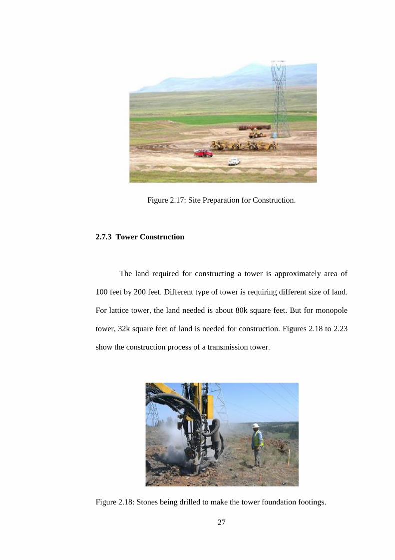
2.7.3 Tower Construction
The land required for constructing a tower is approximately area of
100 feet by 200 feet. Different type of tower is requiring different size of land.
For lattice tower, the land needed is about 80k square feet. But for monopole
tower, 32k square feet of land is needed for construction. Figures 2.18 to 2.23
show the construction process of a transmission tower.
Figure 2.18: Stones being drilled to make the tower foundation footings.

28
Figure 2.19: Anchor bolts cage is prepared to strengthen the tower.
Figure 2.20: Anchor bolts cage is installed.
Figure 2.21: Another hole being drilled for tower footing.

29
Figure 2.22: The components of tower are moved by using helicopter.
Figure 2.23: A crane being used to build the tower.
2.7.4 Substation Construction
The construction of a substation would takes around six to nine months.
Land needed for substation is about 435k ft2. Figure 2.24 shows the substation
construction.

30
Figure 2.24: Substation under Construction.
2.7.5 Conductor Stringing
The conductor cables should install at overhead of a tower or
underground to avoid damage to the conductor surface. In stringing process, a
truck with mounted spool is utilized to pull the conductor cables without using
additional land for tower construction. The direction of line can be severely
changed due to the deviation occurred at diversion tower.
2.8 Design Features of HVDC Transmission System
By referring the design of transmission system, there are some factors
can be considered to reduce the impacts of environment during the
construction and operation of transmission system.

31
2.8.1 Route Selection
Route selection is the major design consideration to reduce the impacts
of HVDC transmission system. In general, route selection is highly forced due
to the uncertain factors, but to the extended practical, the following route
selection factors must be considered which can reduce the impacts of the
system:
• To avoid sensitive natural habitat and swampland.
• To avoid sensitive areas such as public park and uncultivated
land.
• To avoid of farmland.
• To avoid historic buildings.
• To avoid residential areas.
2.8.2 Transmission Line Design
When designing the transmission line, there are few factors need to be
considered such as materials, number of conductors, type of structures, type of
wires and line markers. The impacts of transmission line also can be reduced
by the following factors:
• Tower design: In design of transmission tower, the main consideration
is the types of tower used for constructing the transmission system.
The transmission tower is chosen and designed to be tall, overhead

32
lines support and withstand the force from strong wind. Figure 2.25
shows the two different types of transmission tower.
Figure 2.25: Typical Power Transmission Towers: Lattice type,
Monopole.
• Phase to ground clearances: It is the process of removing spacing
between the conductors. It may involve to the clearances between the
lien and other electric lines.
• Specific mitigation features: The transmission line impacts still able
to be reduced by other design considerations. For example, the conflict
between bird or aircraft can be prevented by utilizing the ball markers
and flappers.
33
2.9 Cost of Transmission System
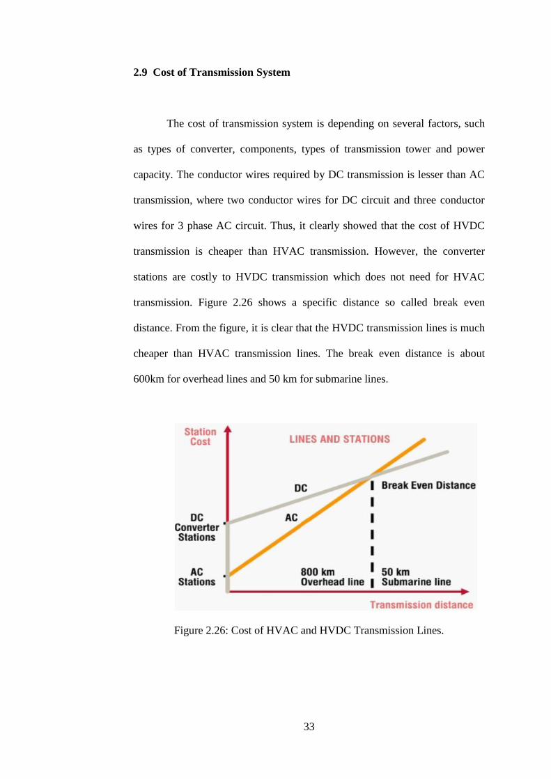
The cost of transmission system is depending on several factors, such
as types of converter, components, types of transmission tower and power
capacity. The conductor wires required by DC transmission is lesser than AC
transmission, where two conductor wires for DC circuit and three conductor
wires for 3 phase AC circuit. Thus, it clearly showed that the cost of HVDC
transmission is cheaper than HVAC transmission. However, the converter
stations are costly to HVDC transmission which does not need for HVAC
transmission. Figure 2.26 shows a specific distance so called break even
distance. From the figure, it is clear that the HVDC transmission lines is much
cheaper than HVAC transmission lines. The break even distance is about
600km for overhead lines and 50 km for submarine lines.
Figure 2.26: Cost of HVAC and HVDC Transmission Lines.

34
2.9.1 Cost of HVDC Transmission Components
In this section, the cost of HVDC transmission components is studied
and discussed. The components cost would be based on LCC-HVDC and
VSC-HVDC. One of the challenges of this study is lack of data about the
components cost due to the private and confidential. However, an attempt to
provide the data as accurate as possible. All the data are referred from
references and the prices presented are in Euros, €.
2.9.1.1 Cost of LCC-HVDC Components
In 2002, a LCC – HVDC interconnection is built between Greece and
Italy. The system is connected by using submarine cables. According to
(Lazaridis, L. P., 2005), the 500 MVA converter stations are cost about 80M
Euros and providing a price of 0.08 Euros per VA. To make the data accurate,
the price of this case will be used as a reference. The price of submarine DC
cables is compared between the year of completion and year 2004, as shown in
Table 2.2. Table 2.3 lists the cost of cables per km.
Table 2.2: DC Cable Cost according to Power Capacity.
Cable
capacity
(MW)
Project Name Price in year of
completion
Price in 2004
600 Sweden-
Poland link
€860/km in year 2002. €900/km

35
550 Iceland link €820/km €724/km
500 Italy-Greece
link
€660/km in year 2002. €700/km
440 Skagerrak 3
link
€170 M €700/km
Table 2.3: Cable Cost per km for LCC-HVDC Transmission System.
Rated Power for MI cable (MW) 600 500 440 300 250 150
Cost (M€/km) 0.85 0.74 0.67 0.51 0.45 0.32
2.9.1.2 Cost of VSC-HVDC Components
From the ABB technical report, the price of VSC-HVDC converter
station is about 0.12 Euros per VA. There are three different power rated of
cables used such as 250, 350 and 500 MW. All these cables have
approximately rated voltage of 150 kV. The installation cost of the cable will
be 100k Euros per km and hence, a pair of cable will be 200k Euros per km.
The Table 2.4 shows the cost of cable per km for VSC – HVDC transmission
system.
Table 2.4: Cable Cost per km for VSC – HVDC Transmission System.
Rated power for cable (MW) 250 350 500
Cost for each cable pair (M€/km) 0.31 0.45 0.61

36
2.9.2 Cost Structure of HVDC Transmission System
Other than that, there are many factors can be involved to the cost of
HVDC transmission system, such as types of converter station, components,
types of transmission tower, power capacity and environment conditions.
Figure 2.27 shows the typical cost structure of a converter station, whereby 20%
of the cost goes to the valves, 16% of the cost goes to the converter and
transformers.
Figure 2.27: Cost Structure of HVDC Transmission System.
2.9.3 Cost of HVAC Components
From the cost of HVDC components, it is clear that the data is divided
into two aspects which are the converter station cost and the cable cost.

37
Although these two aspects are important, but the HVAC components listed
for the costing are more extensive. The HVAC components are:
• Transformers.
• Compensators.
• 132 kV, 220 kV and 400 kV three-core, XLPE, submarine cables.
• Cable installation cost.
• Switchgear.
2.9.3.1 Cost of Transformers
From the review of (Lazaridis, L. P., 2005), the cost of transformers is
depending on the rated power. As shown in Table 2.5, higher rated power
makes the cost of transformers become higher.
Table 2.5: Cost of Transformers.
Rated
Power
(MVA)
800 722 630 400 300 250 200 180 150 125 100 50
Cost
(M€)
5.05 4.68 4.23 3.01 2.44 2.11 1.79 1.66 1.45 1.26 1.07 0.64
38
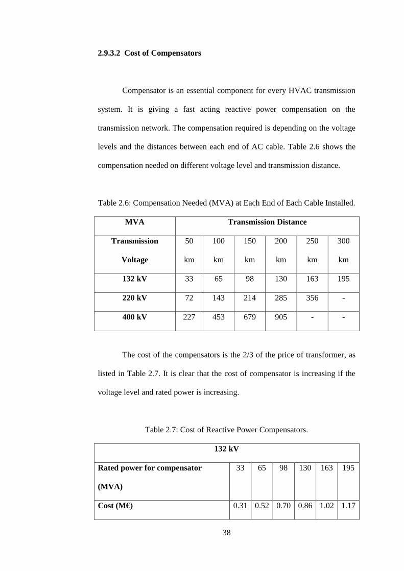
2.9.3.2 Cost of Compensators
Compensator is an essential component for every HVAC transmission
system. It is giving a fast acting reactive power compensation on the
transmission network. The compensation required is depending on the voltage
levels and the distances between each end of AC cable. Table 2.6 shows the
compensation needed on different voltage level and transmission distance.
Table 2.6: Compensation Needed (MVA) at Each End of Each Cable Installed.
MVA Transmission Distance
Transmission
Voltage
50
km
100
km
150
km
200
km
250
km
300
km
132 kV 33 65 98 130 163 195
220 kV 72 143 214 285 356 -
400 kV 227 453 679 905 - -
The cost of the compensators is the 2/3 of the price of transformer, as
listed in Table 2.7. It is clear that the cost of compensator is increasing if the
voltage level and rated power is increasing.
Table 2.7: Cost of Reactive Power Compensators.
132 kV
Rated power for compensator
(MVA)
33 65 98 130 163 195
Cost (M€) 0.31 0.52 0.70 0.86 1.02 1.17

39
220 kV
Rated power for
compensator(MVA)
72 143 213 285 356
Cost (M€) 0.55 0.92 1.25 1.55 1.83
400 kV
Rated power for
compensator(MVA)
227 453 679 906
Cost (M€) 1.31 2.20 2.98 3.69
2.9.3.3 Cost of AC cable
With voltage level of 400 kV AC cable, the cost is about 1.96M Euros
per km. The installation cost for the HVAC cables will be 100k Euros per km.
One of the considerations is that only one cable can be place when installing
one path of cable.
2.9.3.4 Cost of Switchgear
Lastly, the switchgear costs are presented in Table 2.8 with four
different voltage levels. Switchgear is used as a disconnect circuit breaker to
protect and control the equipment in the transmission system.
Table 2.8: Cost of Switchgear.
Rated voltage for switchgear (kV) 33 132 220 400
Cost (M€) 0.06 0.13 0.19 0.31

40
2.10 HVDC Transmission System in Malaysia
The 300/600 MW Thailand – Malaysia HVDC system is the first
HVDC interconnection in ASEAN region. At the beginning, this HVDC
interconnection project is planned to implement in between Malaysia and
Thailand in 1997. The project is then started on February 2000 and completed
on September 2001.
As shown in Figure 2.28, the HVDC system is connected as monopolar
300 kV overhead transmission lines with rated power of 300 MW. Power is
transmitted from converter station at Gurun, Kedah to another converter
station at Khlong Ngae, Thailand over the distances of 110 km as shown in
Figure 2.29.
On 15 August 1997, a contract is signed between TNB and Electricity
Generating Authority of Thailand (EGAT) to develop this HVDC
interconnection project (Halirni Abdullah, M., 2003). The purposes are:
• To share the spinning reserve between TNB and EGAT AC systems.
• To get more economical power exchange between both countries due
to the different daily peak consumption periods.
• Emergency assistance to either AC network.
• Reactive power support (voltage control) to both AC networks.

41
Figure 2.28: Monopolar HVDC System between Malaysia and Thailand.
Figure 2.29: The Thailand – Malaysia Interconnection HVDC System.

42
CHAPTER 3
METHODOLOGY
3.1 Introduction
In this chapter, a real case study for HVDC transmission system is
selected to compare with a HVAC transmission case study based on the
background, layout, design features and components required. Moreover, a
simulation is carried out for each transmission system to compare and analyze
the fault current effects.
3.2 Background
3.2.1 Xiangjiaba – Shanghai HVDC Transmission System
Countries such as China and India are growing rapidly in their
economies and hence, the demand of energy is increasing for both countries.
In China, 800 kV Xiangjiaba – Shanghai HVDC transmission system is built
and rated for 6400 MW. It is commissioned by State Grid Corporation of
China (SGCC) to transmit the hydro power from Xiangjiaba Dam to the
Shanghai city. SGCC is state-authorized investment and a pilot state holding
company which focus to construct and operate the power grids. In July 2010,
Xiangjiaba – Shanghai HVDC system became the most powerful and longest

43
HVDC transmission system in the world. However, the power capacity record
is taken over by the 800 kV Jinping–Sunan HVDC with rate of 7200 MW in
December 2012 and distance record is taken over by Rio – Madeira HVDC,
Brazil in 2013.
As shown in Figure 3.1, the Xiangjiaba – Shanghai HVDC
transmission system able to transmit the power over distances of 2000 km
from south west of China to Shanghai on eastern of China. Other than that, the
800 kV DC voltage is operated to minimized the losses from transmission.
With eco-friendly hydro power generator and low power losses of HVDC
transmission system, the CO2 p.a. is save up to 44 million metric tons
compared to local power supply with energy-mix.
In Fulong converter station, there are ten DC converters have been
installed for the lines by Siemens Energy. Furthermore, Siemens cooperate
with XPR to install the six-inch thyristor valve based towers and connectors.
Table 3.1 is clearly listing the information of Xiangjiaba – Shanghai HVDC
System.
Table 3.1: Information of Xiangjiaba – Shanghai HVDC System.
Customer State Grid Corporation of China and
XD Xi’an Power Rectifier Works (XPR)
Project name Xiangjiaba
Location Xiangjiaba to Shanghai
Type of plant Long-distance transmission,

44
2070 km
Power rating 6400 MW, bipolar
Voltages levels ± 800 kV DC,
525 kV AC
Type of thyristor Electric-triggered thyristor, 8 kV
(6 inches)
Figure 3.1: The Xiangjiaba – Shanghai HVDC Transmission System.
3.2.2 Raichur–Solapur HVAC Transmission System
In India, the 765 kV Raichur – Solapur HVAC transmission system has
been energized by Power Grid Corporation of India Ltd. This HVAC
transmission system is commissioned on December 2013 and is connected
from Raichur in Karnataka to Solapur in Maharashtra with a distance of 208
km as shown in Figure 3.2. The line is implemented under the scheme of
synchronous interconnection between Southern Region and Western Region.

45
With this interconnection, the power system of India has become one of the
largest synchronous operating grids in the world with the total power capacity
of 235 GW. Subsequently, the goal of ‘One Nation – One Grid – One
Frequency’ has been achieved.
Figure 3.2: The Raichur – Solapur HVAC Transmission System.
3.3 Layout
3.3.1 Layout of the Xiangjiaba – Shanghai HVDC Transmission System
The Xiangjiaba – Shanghai HVDC transmission system will transmit
electrical power with lower power losses from Xiangjiaba, Fulong Station,
Sichuan Province to Shanghai through a DC line length of 2000 km.
The system is using bipolar type connection which connecting Fulong
converter station to Fengxia converter station in Shanghai. The Fulong
converter station so called rectifier, is located about 10 km away from the

46
south of Xiangjiaba hydro dam. Four of 500kV AC lines are used to make the
connection between Fulong converter station and generation stations.
Meanwhile, the Fengxia converter station so called inverter that
located around 45 km from the center of Shanghai. It is linked to the Nanhui
station with three of 500 kV AC lines in Shanghai. The layout of power
system is illustrated in Figure 3.3.
Figure 3.3: Power System Layout for Xiangjiaba – Shanghai HVDC.
3.3.2 Layout of the Raichur – Solapur HVAC Transmission System
The Raichur – Solapur HVAC transmission system is categorized into
two parts which are transmission system and distribution system. Each of the
system can be divided into two stages. First stage is the primary transmission
and next is the secondary transmission as shown in Figure 3.4. The generation
and transmission are three phase type.

47
For primary transmission, the electrical power is generated at 220 kV
in a power plant. This generating voltage is then stepped up to 765 kV. The
purpose of stepping up the voltage is to minimize the power losses when
transmitting the electrical power. After that, the voltage is stepped down to
400 kV at a receiving station (RS).
For secondary transmission, the RS is connected to the substations
which located near the city. The transformer is stepping down the voltage to
11 kV at substation. Then, the first distribution also called as primary
distribution is using this voltage to supply to bigger consumers like industrials.
At last, secondary distribution system is transmitting the 415 V stepped
down voltage to other consumers.

48
Figure 3.4: Power System Layout for Raichur – Solapur HVAC.
3.4 Design Features
3.4.1 Design Features of the Xiangjiaba – Shanghai HVDC Transmission
System
220 kV
220/765 kV
kV
765 kV
400 kV
400 kV
400/11 kV
kV 11 kV
11 kV
11 kV/ 415 V
49
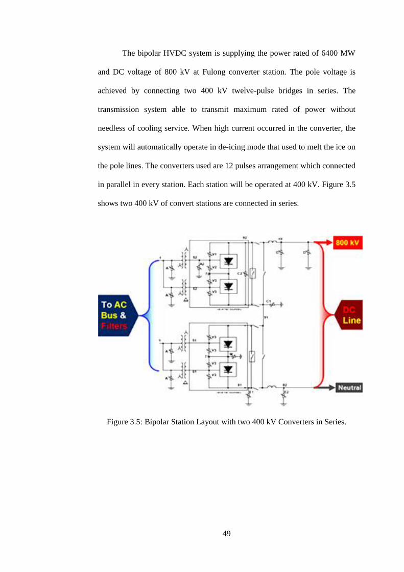
The bipolar HVDC system is supplying the power rated of 6400 MW
and DC voltage of 800 kV at Fulong converter station. The pole voltage is
achieved by connecting two 400 kV twelve-pulse bridges in series. The
transmission system able to transmit maximum rated of power without
needless of cooling service. When high current occurred in the converter, the
system will automatically operate in de-icing mode that used to melt the ice on
the pole lines. The converters used are 12 pulses arrangement which connected
in parallel in every station. Each station will be operated at 400 kV. Figure 3.5
shows two 400 kV of convert stations are connected in series.
Figure 3.5: Bipolar Station Layout with two 400 kV Converters in Series.

50
3.4.2 Design Features of the Raichur – Solapur HVAC Transmission
System
In Raichur – Solapur HVAC system, the transmission lines are
designed by 765 kV single circuit. Thus, larger land space is required for this
765 kV transmission line, approximately width of 200 feet. Besides, high
tension insulators are also widely used in this transmission line. Figure 3.6
shows the high tension insulator which designed with two corona rings.
Figure 3.6: High Tension Insulator.
3.5 Main Components
3.5.1 The Xiangjiaba – Shanghai HVDC Transmission System
3.5.1.1 Thyristor Valves
The thyristor valves are designed by six inch YST130 type of
thyristors. There are 56 units of thyristors in every valve. From the previous
Corona Ring

51
research, these thyristors have been exploited and widely used in the
applications with high current. It was the first HVDC transmission project that
using six inch thyristors.
3.5.1.2 Converter Transformers
In Xiangjiaba – Shanghai HVDC Transmission System, the
transformers are designed in single phase with two windings. The transformers
are made either in China or in Sweden.
3.5.1.3 Smooth Reactors
The smoothing reactors used are in air insulated type. There are two
units of smooth reactors installed at 800 kV voltage side, while another two
units installed in the neutral voltage side.
3.5.2 The Raichur – Solapur HVAC Transmission System
3.5.2.1 Generators
Generator is one of the important components for power system. It is
synchronous type and converting the mechanical energy to electrical energy.
Generator consists of stator and rotor. The stator is the stationary part that has
conductors embedded in the slots. While, the rotor is mounted on the shaft and
rotates inside the stator.

52
3.5.2.2 Transformers
Normally, the transformers are used in the substations. It able to step
up or down the system voltage. The voltage can only be stepped up when the
power transmitted at the generating end, while the voltage is gradually stepped
down to reach finally to working voltage level at all the subsequent substations.
3.5.2.3 Transmission Line
The transmission line is a conductor designed to transmit the electric
power from generation station to the distribution system.
3.5.2.4 Bus Bars
Bus bars are used to connect the transmission lines which are operating
at same voltage directly. These bus bars are made either by copper or
aluminum.
3.6 Short Circuit Current in HVAC and HVDC Transmission Systems
Sometimes, the electric faults are occurred when large amount of
current flow through an alternative path. Due to this, the power becomes
unstable, a serious damage on equipment, people injured or may cause people
to death. In transmission line, the symmetrical faults are approximately 5%
(Mizanur Rahman, Md. et al, 2014).

53
If some phases are affected, the result of the asymmetrical fault
becomes more complicated to determine. This is due to the simplifying
assumption of equal current magnitude is being not suitable in all phases.
Asymmetric faults consist of three types such as line to line fault, line to
ground fault and double line to ground fault. Line to line fault is happened
when two lines have contacted each other. A line to ground fault is happened
between a line and ground. It can be easily caused by lightning or other storm
damage. For double line to ground fault, it is happened when two lines are
shorted to ground. It is usually caused by storm damage.
The short circuit current also known as fault current is occurred when
the fault is detected in transmission system. A heavy current or high level fault
current flow through the circuit can destroy the insulation system and cause
the power surges the damage equipment that powered by current. Furthermore,
the devices are charged to manage the electric shock released to the human
body. However, the electric shock also can cause death depends on the nature
of the fault current.
Hence, a simulation is carried out for HVAC and HVDC transmission
systems to compare and analyze the fault current effects. Both systems are
using same parameters to have better analysis and results.

54
3.6.1 Simulation of HVAC Transmission System
Figure 3.7 shows a simulation model for HVAC transmission system
by three phase and power rated of 1680 MW. The voltage level is set at 500
kV with the frequency of 50 Hz. The generated power is transmitted from a
power plant to a substation through transmission distances of 300 km. Each
line has series compensated by shunt capacitor in order to increase the power
quality and power capacity. This compensator helps to reduce the losses from
active and reactive power and increase the transmission power to maximum.
In final stage, 1650 MW of power will be received at substation.
Figure 3.7: Simulation Model of HVAC Transmission System.

55
3.6.2 Simulation of HVDC Transmission System
Figure 3.8 shows a simulation model for HVDC transmission system
by utilizing 12 pulse arrangement of thyristor converter. Then, the power is
rated at 1680 MW and the voltage level is set at 500 kV with frequency of 50
Hz. The generated power is transmitted from a power plant to a substation
through transmission distances of 300 km. The rectifier and the inverter are
connected in series with two universal bridges. 0.9 H of smoothing reactors
are then installed near the converters. The smoothing reactors are applied to
minimize the fault current and avoid the resonance occurs in DC circuit. At
last, 1645 MW of power will be received at substation.
Figure 3.8: Simulation model of HVDC Transmission System.

56
CHAPTER 4
RESULT AND DISCUSSION
4.1 Design Aspects for Transmission Lines
When designs the AC and DC transmission lines, electrical aspect and
mechanical aspect are the important fields which can affect the cost of a
transmission system.
By looking at the power capacity, the voltage level and the number of
parallel circuits can be determined and used to calculate the cost of
transmission system. Figure 4.1 shows the transmission lines for 800 kV AC
and 500 kV DC.
For mechanical aspect, the conductor designs play an important role
for a transmission system. The number of conductors used can affect the cost
of transmission, this will be discussed in section 4.4. The power capacity and
RoW of transmission line used in the HVDC China and HVAC India is
showed in Table 4.1.
Table 4.1: AC and DC Transmission Line.
Transmission Line 800 kV AC 500 kV DC
Capacity (MW) 2k 3k

57
RoW (m) 85 50
Figure 4.1: Transmission Lines for 800 kV AC and 500 kV DC.
4.2 Number of Lines in Parallel
The number of lines connected in parallel is determined by using the
requirement of conductors. The corona noise is one of the factors that affect in
selecting the number of line. Table 4.2 showed that the number of lines
required when using HVAC or HVDC at different voltage levels.
Table 4.2: Number of Lines required for HVAC and HVDC Systems.

58
The effectiveness of HVDC transmission lines at higher voltage levels
is clearly demonstrated in Figure 4.2.
Figure 4.2: RoW for 800 kV HVDC and 765 kV HVAC Transmission
Towers.
4.3 Line Losses
Besides the design of conductors for HVAC and HVDC, the cost of the
transmission system can be affected by power losses. The resistive losses
occurred to identify the cross section of conductor in HVAC lines. In order to
get better design of the conductor bundle, the AC corona losses have to be
considered. The corona losses are higher during the condition of rain.
For HVDC lines, there are like HVAC lines in which the resistive
losses occurred to identify the conductor cross section. DC corona losses are
lower compared to AC and hence the concern level of conductor design is
lesser. Power losses of DC and AC lines are shown in Figure 4.3. It is clearly
seen that the HVDC lines are lesser losses compared to HVAC lines in
weather conditions.
800 kV HVDC
765 kV HVAC

59
Figure 4.3: Power Losses on AC and DC Lines.
4.4 Conductor Load on Tower
From the literature review, it is clearly showed that the HVDC
transmission are utilizing lesser number of conductors compared to HVAC
transmission. At the same voltage level, the HVDC conductors used are
almost half of the HVAC conductors as shown in Figure 4.4.
Figure 4.4: Total Conductor Load on AC and DC Towers.

60
4.5 Comparison between HVDC China and HVAC India
In Table 4.3, the technical feasibility, environmental impact and
economic aspects are being be compared between HVAC in India and HVDC
in China.
Table 4.3: Comparison between HVDC China and HVAC India.

61
4.6 Simulation Results
4.6.1 Single line to Ground Fault
For single line to ground fault, HVAC transmission system (37 kA in
Figure 4.5) received higher fault current as compared to HVDC transmission
system (29 kA in Figure 4.6).
Figure 4.5: Single Line to Ground Fault Current for HVAC System.
Figure 4.6: Single Line to Ground Fault Current for HVDC System.

62
4.6.2 Line to line Fault
Line to line fault is another type of asymmetrical fault. At receiving
end of HVAC transmission system, the results clearly show the fault current is
high (34 kA in Figure 4.7). But under same condition, the fault current is
lower (20 kA) at HVDC transmission system as shown in Figure 4.8.
Figure 4.7: Line to Line Fault Current for HVAC System.
Figure 4.8: Line to Line Fault Current for HVDC System.

63
4.6.3 Fault in Transmission Line
Referring to the Figure 4.9, the transmission line fault is about 12 kA
for HVAC transmission system. The fault is happened at the transmission line
part, but the fault is happened at the receiving end part for single line to
ground. For HVDC transmission system, the transmission line fault is
happened at DC transmission line part. By comparing both system, the fault in
HVAC transmission system (12 kA in Figure 4.9) is higher than HVDC
transmission system (700 A in Figure 4.10).
Figure 4.9: Fault Current at Transmission Line for HVAC system
Figure 4.10: Fault Current at Transmission Linefor HVDC system

64
4.7 Comparison of Fault Current
The comparison of fault current of HVAC and HVDC system is
presented in Table 4.4with different fault types. The results showed that the
effects of fault current can easily damage the HVAC transmission system but
effects are lesser in HVDC transmission system.
Table 4.4: Fault Current Comparison for HVAC and HVDC Systems.
Fault HVAC (Max. Value) HVDC (Max. Value)
Single line to ground 37 kA 29 kA
Line to line 34 kA 20 kA
Transmission line 12 kA 0.7 kA

65
4.8 Malaysia Conditions
Malaysia is a tropical country with rich of soil and large amount
sunlight produced all the time. In the beginning, agriculture plays a major role
for the economy of a country. However, the industrial activity has been
focused more to improve the economy. The concept of “Malaysia
Incorporated” successfully brought Malaysia to change the agricultural based
economy to an industrial based within two decades. With the strong growth of
economy, the demand of electricity is increased on last few decades.
In Malaysia, the electric energy demands are supplied by Tenaga
Nasional Berhad (TNB). According to the TNB annual report, the maximum
energy demand is about 17,788 MW in 2016, expected to reach 274 TW in
2030. The energy demand rate is approximately 3.5% rise every year. To
fulfill the electric energy demand, large power stations are being built and
commissioned. Most of the generation stations are using natural resources like
gas, coal and hydro. The total generation capacity installed is 12,013.4 MW. It
comprises of 5,694.9 MW gas power stations, 3971.6 MW coal power stations
and 2,347 MW hydro power stations.
As the power capacity is increased, a new and longer transmission
lines need to be constructed. This may increase the cost and restriction on
Rights-of-Way (ROW). Therefore, high efficient technology like HVDC
transmission is able to overcome the problems. The HVDC transmission
system has lower investment cost, lesser land use, lower power losses, lesser
66
environment impacts and other benefits. However, there are some challenges
to implement the HVDC transmission system in Malaysia.
In Malaysia, the land matters are under control and power by the state
governments. To build the HVDC transmission, a compensation is required for
the commercial land owners. Construction of HVDC transmission can be
delayed when the land owners cannot be located or the land under lease.
Furthermore, development areas such as new airport, industries or new road
will prevent the construction.
Other than that, the local power company is applying a rule that all the
components of transmission need to be sourced or made from local
manufacturers. However, the insulator is given to be imported. One main issue
is the local industries have difficult to meet the requirements of transmission
tower. They may provide the wrong size, strength or thickness of the
components.
Malaysia involved many rain forests, mountains and rivers. The
movement of heavy equipment became the main challenge to build the HVDC
project. On rugged terrain, the land and helicopter transports are required to
move the equipment and materials. As a consequence, the equipment and
materials can be damaged if mishandled. Thefts on copper rods, steel parts,
and aluminum conductors are also common today because of the increasing
value in the market.
67
CHAPTER 5
CONCLUSION AND RECOMMENDATIONS
5.1 Conclusion
In early of electric power system, most of the transmission and
distribution network are formed with AC. This is due to the voltage levels can
be easily changed by simple and reliable transformers. It was a strong
technology and has been used for few decades. However, AC has some
limitations that lead the AC unable to technically use for long distances. The
absence of reactive compensations is one of the issues which can cause the
HVAC transmission system unstable. Thus, conventional AC technology is
preferred to apply in the transmission system. A simple current conversion
applied to make the HVDC transmission system more efficient and stable. Due
to this, extra costs are needed to install the converters in HVDC transmission
system. However, HVDC transmission system provides more benefits
compared to HVAC transmission system. More conclusions are discussed and
listed as below:
• Break even distances for HVAC and HVDC transmission:
The break-even distance is the distance that indicated the
capital cost savings. The breakeven distance between AC and DC lines

68
is around 600 km for overhead lines, while the breakeven distance of
submarine lines is around 50 km. The cost of HVDC transmission is
significantly lower than HVAC transmission over the longer distance.
This is due to the conductor requirements on AC and DC lines. DC line
is required only two conductors, but three conductors for AC line.
• Short Circuit Current:
Short circuit current as known as fault current, is the common
issue in electric power system. The heavy currents from short circuit
may cause the lines heating or melting. It also can form the arc to
damage elements in the system. In additional, the stability of the power
system can be affected and other equipment can be damaged due to
over-heating. On the other hand, HVDC transmission system is more
stable due to the converters does not contribute to short circuit current.
The system is able to transmit the power smoothly without increasing
the short circuit levels.
• Environmental Aspects:
Environmental issue such as electric magnetic field (EMF) is
being concerning of the public every year. The magnetic field
produced by DC lines is stationary, but AC lines produce alternating
magnetic field. Unlike stationary magnetic fields, the alternating

69
magnetic fields can induce the body currents. Thus, there are more
limits to install the AC transmission lines.
• Benefits:
From this study, it is clearly showed that the HVDC
technologies are more favorable in electrical power transmission and
distribution. The benefits of HVDC transmission systems are
summarized and listed as below:
▪ No limitations on the transmission distances.
▪ More power can be transmitted through same size of tower.
▪ Short circuit current can be reduced by HVDC converters.
▪ Fast control of active and reactive power.
▪ Less environmental disturbances.

70
5.2 Recommendations
One of the recommendations is to continue implement the HVDC
transmission system with higher voltage, 1000 kV. With the similar power
capacity, it can be seen that 1000 kV HVDC lines are better than 1000 kV
HVAC lines for long distance. According to the Feasibility Report of
European Grids and the Power Grids Document of United Nations, 1000 kV
HVAC transmission systems overlay the existing power grids would not be
achieved in the future. Power grids by HVDC technologies should be
maintained and the power capacity with different voltage levels should be
improved.
Other than that, the economy of HVDC transmission can be improved
by introducing the offshore grid. Offshore grid such as windfarm is respected
produce a better market price of the wind energy. Moreover, the HVDC
transmission can be cheaper after the oil and gas power plant is installed from
shore since the price of fossil fuel is increasing.

71
REFERENCES
Behravesh, V. & Abbaspour, N., 2012. New Comparison of HVDC and
HVAC Transmission system. International Journal of Engineering Innovation
& Research, 1(3), 300 – 304.
Saeedifard, M. et al., 2010. DC Power Systems: Challenges and Opportunities.
IEEE PES General Meeting, 1 – 7.
Flourentzou, N., Agelidis, V.& Demetriades, G., 2009. VSC-based HVDC
power transmission systems: An overview. IEEE Transactions on Power
Electronics, 24(3), 592 –602.
Bahrman, M. & Johnson, B., 2007. The ABCs of HVDC transmission
technology. IEEE Power and Energy Magazine, 5(2), 1057– 1069.
Bresesti, P. et al., 2007.HVDC connection of offshore wind farms to the
transmission system. IEEE Transactions on Energy Conversion, 22(1), 37–43.
A Smith, C., Monkhouse, D. R. & Mcintosh, A., 2015. Technology impact on
the success of HVDC interconnector projects – a UK developers perspective.
11th IET International Conference on AC and DC Power Transmission, 1 – 5.
Andersen, B. R., 2006. HVDC Transmission - Opportunities and Challenges.
The 8th IEE International Conference on AC and DC Power Transmission, 24
– 29.
Buijs, P., Cole, S. & Belmans, R., 2009. TEN-E Revisited: Opportunities for
HVDC Technology. 6th International Conference on the European Energy
Market, 1 – 6.
Meah, K. & Ula, S., 2007. Comparative Evaluation of HVDC and HVAC
Transmission Systems. IEEE Power Engineering Society General Meeting, 1
– 5.
Francos, P. L. et al., 2012. INELFE – Europe’s first integrated onshore HVDC
interconnection. IEEE Power and Energy Society General Meeting, 1 – 8.
Halirni Abdullah, M., 2003. Operational Performance of the Malaysia –
Thailand 300/600 MW HVDC Interconnection. National Power and 'Energy
Conference (PECon), 317 – 321.
Cole, S., Hertem, D. V. & Belmans, R., 2007. Connecting Belgium and
Germany using HVDC: A Preliminary Study. IEEE Lausanne Power Tech,
1215 – 1219.

72
Weichao, Z. et al., 2012. Review of DC Technology in Future Smart
Distribution Grid. IEEE PES Innovative Smart Grid Technologies, 1 – 4.
Hammerstrome, D. J., 2007. AC Versus DC Distribution Systems --- Did We
Get Right? IEEE Power Engineering Society General Meeting, 1 – 5.
Cole, S. & Belmans, R., 2009. Transmission of Bulk Power. IEEE Industrial
Electronics Magazine, 3, 19-24.
Dorn, J. et al., 2013. Transformation of the Energy System in Germany –
Enhancement of System Stability by Integration of innovative Multilevel
HVDC in the AC Grid. International ETG-Congress 2013; Symposium 1:
Security in Critical Infrastructures Today, 1 – 6.
Davies, M. et al., 2008. HVDC PLUS – Basics and Principle of Operation.
Special Edition for Cigré Exposition, Paris.
Toledo, P. F. D., 2003. Feasibility of HVDC for City Infeed. Royal Institute of
Technology, Department of Electrical Engineering, 1 – 170.
Henry, S., Denis, A. M. & Panciatici, P., 2010. Feasibility study of off-shore
HVDC grids. IEEE PES General Meeting, 1 – 5.
Bahrman, M. P. & Johnson, B. K., 2007. The ABCs of HVDC Transmission
Technology. IEEE Power & Energy Magazine, 5(2).
Halder, T., 2013. Comparative Study of HVDC and HVAC for a Bulk Power
Transmission. International Conference on Power, Energy and Control
(ICPEC), 139 – 144.
Bohari, Z. H. et al., 2016. TECHNICAL REVIEW OF THE ASEAN GRID
POWER INTERCONNECTION PROJECTS. Journal of Theoretical and
Applied Information Technology, 86(1), 173 – 183.
Wang, H. & Redfern, M. A., 2010. The Advantages and Disadvantages Of
Using HVDC To Interconnect AC Networks. 45th International Universities
Power Engineering Conference (UPEC).
Parliament of Malaysia, 2004. Electricity supply Act 1990 (Act 447) and
Electricity supply (successor company) Act 1990 (Act 448) and Electricity
Regulations 1994. International Law Book Services Publication.
Wang, S. et al., 2008. Economic Assessment of HVDC Project in Deregulated
Energy Markets.
Mohd Yusof, Z. & Sivadass, T., 2006. CONSTRUCTION MANAGEMENT
OF POWER TRANSMISSION LINES - LOGISTICS AND CHALLENGES.
6th Asia-Pacific Structural Engineering and Construction Conference, 60 – 67.

73
Kalair, A., Abas, N. & Khan, N., 2015. Comparative study of HVAC and
HVDC transmission systems. Renewable and Sustainable Energy Reviews,
1653 – 1675.
Lazaridis, L. P., 2005. Economic Comparison of HVAC and HVDC Solutions
for Large Offshore Wind Farms under Special Consideration of Reliability.
Royal Institute of Technology, 1 – 182.
Sousa, T. et al., 2012. An Evaluation of the HVDC and HVAC Transmission
Economic. Sixth IEEE/PES Transmission and Distribution: Latin America
Conference and Exposition (T&D-LA), 1 – 6.
Rudervall, R., Charpentier, J. P. & Sharma, R., 2000. High Voltage Direct
Current (HVDC) Transmission Systems Technology Review Paper. Energy
Week 2000, 1 – 17.
Mizanur Rahman, Md. et al, 2014. HVDC over HVAC Power Transmission
System: Fault Current Analysis and Effect Comparison. International
Conference on Electrical Engineering and Information & Communication
Technology (ICEEICT), 1 – 6.
Machado, J., Neves, M. V. &Santos, P. J., 2015. Economic limitations of the
HVAC transmission system when applied to offshore wind farms. 9th
International Conference on Compatibility and Power Electronics (CPE), 69 –
75.
Astrom, U. et al., 2010. The Xiangjiaba-Shanghai 800 kV UHVDC Project,
Status and Special Aspects. International Conference on Power System
Technology, 1 – 6.
Kumar, A.,Wu, D.&Hartings, R., 2007. Experience from First 800 kV HVDC
Test Installation. International Conference on Power Systems, CPRI.

74
APPENDICES
APPENDIX A – Simulation Model of HVAC Transmission System

75
APPENDIX B – Simulation Model of HVDC Transmission System