Embed Size (px)
Citation preview

FEASIBILITY OF AN INNOVATIVE WING MAST FOR A SUSTAINABLE USE IN FISHING BOATS, TANKERS AND CARGO SHIPS
G. BERGAMINI*, G. DEMELIO†*, M. IAMELE†, G. CAMPA† AND L. NETTIS† † Politecnico di Bari – Facoltà di Ingegneria – Dipartimento di Ingegneria Meccanica e Gestionale
Via Re David 200 – 70125 – Bari – Italy Email: [email protected], [email protected], [email protected]
* PoliMech – Strutture Meccaniche Innovative - Strada Scizze, 7 – 70126 Bari - Italy
e-mail: [email protected], [email protected]
Key words: Sustainable Fishing, Wing Mast, SWATH hulls, CFD Analysis, Propellers.
Summary. The purpose of this paper is to demonstrate the feasibility of an innovative project of multi-role fishing boat based on a SWATH catamaran architecture, high efficiency propellers and innovative wind sail auxiliary propulsion by means of a wing mast completely automated. The overall savings in fuel consumption, in reference to a traditional fishing boat of a similar size, the “Serena”, reaches the 90%, while the save in costs due to the only wing mast allows repaying the relative investment in less than 9 years.
1 INTRODUCTION
The idea of a completely renewed architecture for a fishing boat, much more efficient then the traditional ones, was reached as long ago as 1996 after the interventions requested by the ship-owners and developed at the Polytechnic of Bari, in order to reduce the fuel consumption on a 25m fishing boat, the “Serena”. The goal was the reduction of the average daily fuel consumption from 1800 liters to 1200 liters of Diesel oil obtained by means of installation of a big bow bulb and a ducted propeller.
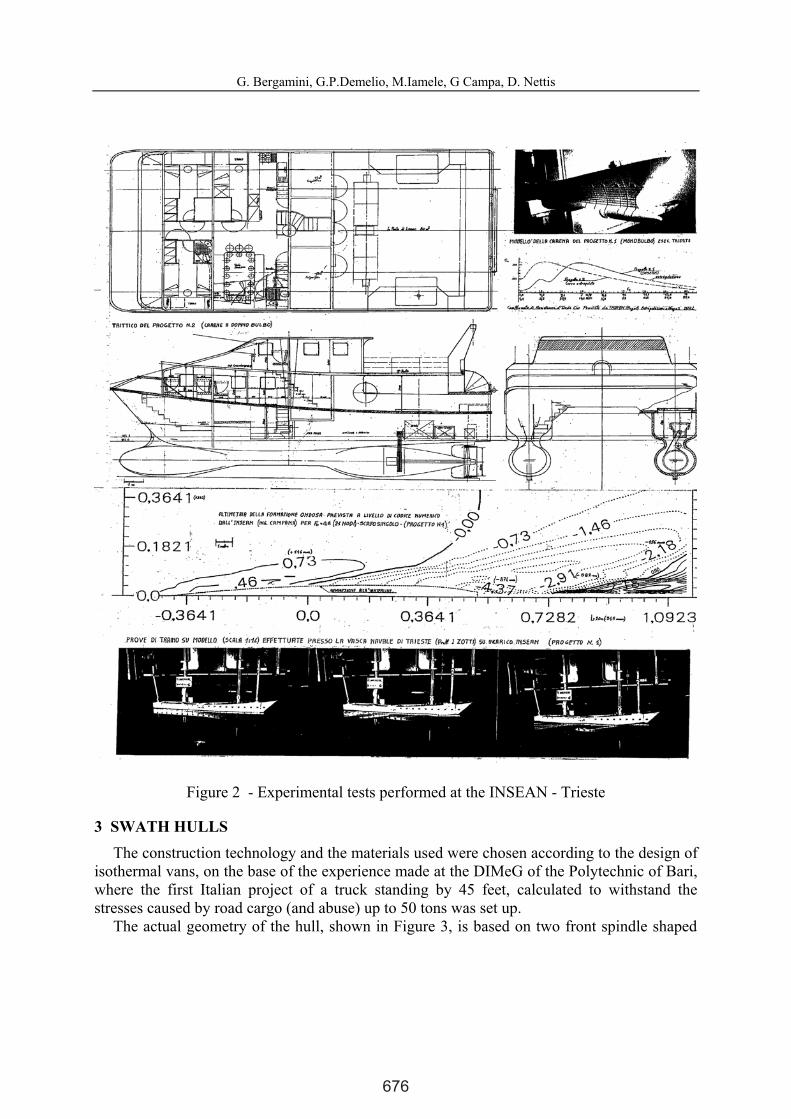
The design of an innovative fishing boat started immediately after the above Serena experience. It was based on a SWATH catamaran architecture (Fig.2) with two submerged long bulbs connected to an upper planning hull to reduce costs in expensive automations related to swath geometries to maintain the water line level. On this architecture, numerical analyses and experimental tests were carried out by the INSEAN (towing tank in Trieste, Fig.3) that demonstrated the validity of the proposal, but evidenced some limits due to friction drag on the large wetted surfaces in the upper planning hulls and to the deep cavity in the water free surface in the zones near to the two propellers.
In that period the computer code for the optimal set up of the geometry of the propellers, already assumed with variable pitch, was only in a first stage. Moreover, the main problem was the prevision of the stall at high attack angles of the tri-foil wing sail adopted. The computer code set up by Lorenzo Bergamini at Mississippi State University in that period was very accurate in evaluating lift and drag but not in the stall prevision. The researches in the
International Conference on Computational Methods in Marine EngineeringMARINE 2011
L.Eça, E. Oñate, J. García, T. Kvamsdal and P. Bergan (Eds)
Feasibility of an Innovative Wing Mast for a Sustainable Use in Fishing Boats, Tankers and Cargo Ships
674
G. Bergamini, G.P.Demelio, M.Iamele, G Campa, D. Nettis
2
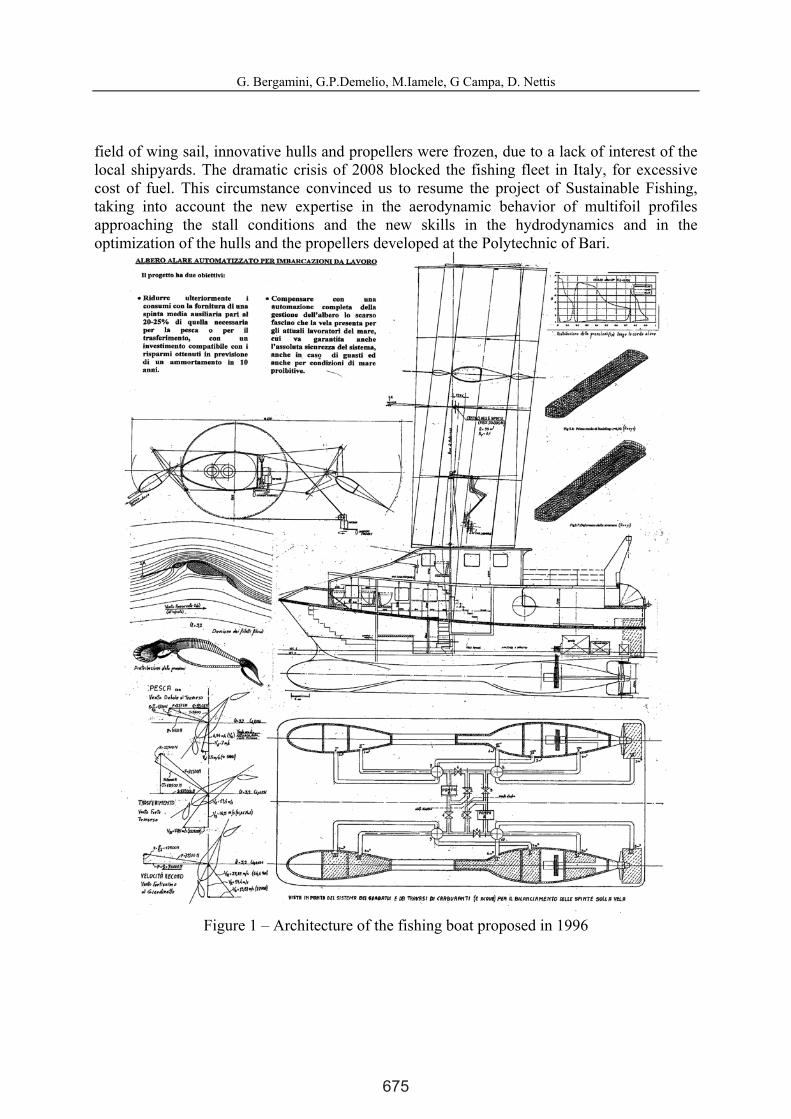
field of wing sail, innovative hulls and propellers were frozen, due to a lack of interest of the local shipyards. The dramatic crisis of 2008 blocked the fishing fleet in Italy, for excessive cost of fuel. This circumstance convinced us to resume the project of Sustainable Fishing, taking into account the new expertise in the aerodynamic behavior of multifoil profiles approaching the stall conditions and the new skills in the hydrodynamics and in the optimization of the hulls and the propellers developed at the Polytechnic of Bari.
Figure 1 – Architecture of the fishing boat proposed in 1996
675
G. Bergamini, G.P.Demelio, M.Iamele, G Campa, D. Nettis
3
Figure 2 - Experimental tests performed at the INSEAN - Trieste
3 SWATH HULLS The construction technology and the materials used were chosen according to the design of
isothermal vans, on the base of the experience made at the DIMeG of the Polytechnic of Bari, where the first Italian project of a truck standing by 45 feet, calculated to withstand the stresses caused by road cargo (and abuse) up to 50 tons was set up.
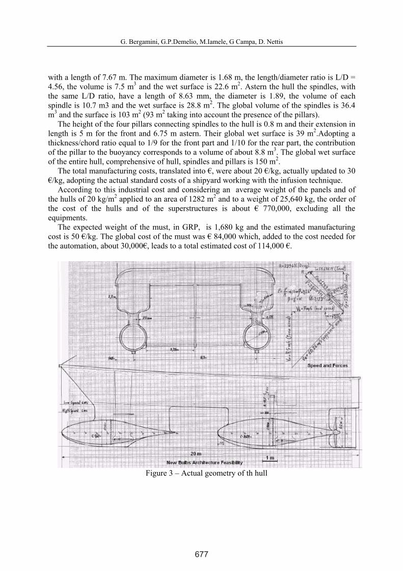
The actual geometry of the hull, shown in Figure 3, is based on two front spindle shaped
676
G. Bergamini, G.P.Demelio, M.Iamele, G Campa, D. Nettis
4
with a length of 7.67 m. The maximum diameter is 1.68 m, the length/diameter ratio is L/D = 4.56, the volume is 7.5 m3 and the wet surface is 22.6 m2. Astern the hull the spindles, with the same L/D ratio, have a length of 8.63 mm, the diameter is 1.89, the volume of each spindle is 10.7 m3 and the wet surface is 28.8 m2. The global volume of the spindles is 36.4 m3 and the surface is 103 m2 (93 m2 taking into account the presence of the pillars).
The height of the four pillars connecting spindles to the hull is 0.8 m and their extension in length is 5 m for the front and 6.75 m astern. Their global wet surface is 39 m2.Adopting a thickness/chord ratio equal to 1/9 for the front part and 1/10 for the rear part, the contribution of the pillar to the buoyancy corresponds to a volume of about 8.8 m3. The global wet surface of the entire hull, comprehensive of hull, spindles and pillars is 150 m2.
The total manufacturing costs, translated into €, were about 20 €/kg, actually updated to 30 €/kg, adopting the actual standard costs of a shipyard working with the infusion technique.
According to this industrial cost and considering an average weight of the panels and of the hulls of 20 kg/m2 applied to an area of 1282 m2 and to a weight of 25,640 kg, the order of the cost of the hulls and of the superstructures is about € 770,000, excluding all the equipments.
The expected weight of the must, in GRP, is 1,680 kg and the estimated manufacturing cost is 50 €/kg. The global cost of the must was € 84,000 which, added to the cost needed for the automation, about 30,000€, leads to a total estimated cost of 114,000 €.
Figure 3 – Actual geometry of th hull
677
G. Bergamini, G.P.Demelio, M.Iamele, G Campa, D. Nettis
5
4 AERODYNAMICS / CFD ANALYSIS The CFD analysis performed for the present work has been carried out by means of two
different platforms: OpenFOAM and Fluent. The main purpose of this study is the achievement of double-checked numerical results for the trifoil wing under analysis. However some preliminary studies have been performed for other high-lift wing profiles in order to further validate the CFD outcome against experimental data in similar flow conditions, as shown in section x.2. After a brief summary of the simulations, in terms of numerical algorithm, boundary conditions and computational grid, the current section will be focused on the aforementioned wing profiles analysis, reporting for each one of them the lift and drag coefficients.
4.1 Numerical Simulations FeaturesThe Navier-Stokes solver selected is characterized by the RANS approach, that represents
the best compromise in terms of reliability of the results and computational requirements. The equations for incompressible flow are solved in steady state by a SIMPLE algorithm. The most common turbulence model in case of flows around wing profiles is the Spalart-Allmaras one [wilcox]. However other turbulence models - e.g. the k-ω sst - have been used in the current work in order to compare different possibilities.
The computational domain is 2D since at the moment we are mainly interested in designing the wing profiles, for which the more requiring 3D-CFD analysis would be useless. However it is worth mentioning that OpenFOAM, differently from Fluent, works only with 3D meshes, therefore the domain and the relative mesh have been extruded in the third dimension, discretized with only 1 cell. Imposing an appropriate “empty” boundary condition on such meshes OpenFOAM is able to perform essentially a 2D simulation [openfoam manual]. Apart from this consideration, the grid adopted for each code is considerably similar - if not the same - since the same strategy has been selected for the discretization: quadrilateral cells for the boundary layer zone and triangular cells in the rest of the domain, far from the wall.
The boundary conditions are: velocity inlet, outlet pressure and freestream at the top and the bottom of the computational domain.
4.2 Results 4.2.1 Gottingen 1069 Profile
This profile, studied in the early 30s, was intended to be employed for high-lift applications. In fact the experimental results obtained at that time clearly show that this profile is able to achieve Cl=1.8 and Cd=0.28 for Re=3E5 and an angle of attack of 17°. Therefore the purpose of the CFD analysis here proposed consists of obtaining the lift and drag coefficients in similar flow conditions. As previously specified, the outcome of Fluent and OpenFOAM will be then compared with the experimental data.
The wing chord is 2 [m], the simulation is characterized by an inlet velocity of 3.0 [ms-1], outlet pressure of 101325.0 [Pa], Kinematic Viscosity of 1.57E-005 [m2s-1] and density equal to 1.176 [kgm-3], all derived from the Reynolds number and considering the air flow at ambient conditions.
678

G. Bergamini, G.P.Demelio, M.Iamele, G Campa, D. Nettis
6
Concerning the discretization of the computational domain, characterized by a width equal to 100 times the wing chord, the computational grid is composed of 227254 cells with the height of the first cell near the wall equal to 1E-5 [m]. The grid has been kept the same for both the codes under consideration. The height of the first cell near the wall is such that no wall functions is needed for the Spalart-Allmaras model, since the y+ should range below 5.
The results, in terms of velocity contours, are shown in Figure 4, where the comparison between OpenFOAM and Fluent is set. Moreover the flow separation on the suction side occurs in a similar location.
Looking at the value obtained for lift and drag coefficients, again the two simulations are in good agreement. In fact both of them are able to correctly predict the lift coefficient with respect to experimental data, although they underestimate the drag coefficient. However such values can be surely retained acceptable.
(a) (b)
Figure 4 : Comparison of the results for the high-lift “Gottinga” profile for OpenFOAM (a) and Fluent (b)
Lift and Drag Coefficient
Experimental OpenFOAM Fluent
Cl 1.8 1.81 1.79
Cd 0.28 0.19 0.21
Table I: Grid main features 4.2.2 Hansen Trifoil
Rosander and Bloch in Ref.[modern windship] have shown a geometry composed of three asymmetric airfoils (Slat, Main and Flap). They show that at a wind speed of 25 [ms-1] at an
679
G. Bergamini, G.P.Demelio, M.Iamele, G Campa, D. Nettis
7
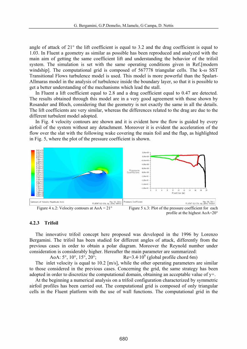
angle of attack of 21° the lift coefficient is equal to 3.2 and the drag coefficient is equal to 1.03. In Fluent a geometry as similar as possible has been reproduced and analyzed with the main aim of getting the same coefficient lift and understanding the behavior of the trifoil system. The simulation is set with the same operating conditions given in Ref.[modern windship]. The computational grid is composed of 567778 triangular cells. The k-ω SST Transitional Flows turbulence model is used. This model is more powerful than the Spalart-Allmaras model in the analysis of turbulence inside the boundary layer, so that it is possible to get a better understanding of the mechanisms which lead the stall.
In Fluent a lift coefficient equal to 2.8 and a drag coefficient equal to 0.47 are detected. The results obtained through this model are in a very good agreement with those shown by Rosander and Bloch, considering that the geometry is not exactly the same in all the details. The lift coefficients are very similar, whereas the differences related to the drag are due to the different turbulent model adopted.
In Fig. 4 velocity contours are shown and it is evident how the flow is guided by every airfoil of the system without any detachment. Moreover it is evident the acceleration of the flow over the slat with the following wake covering the main foil and the flap, as highlighted in Fig. 5, where the plot of the pressure coefficient is shown.
Figure 4 x.2: Velocity contours at AoA = 21° Figure 5 x.3: Plot of the pressure coefficient for each profile at the highest AoA=20°
4.2.3 Trifoil
The innovative trifoil concept here proposed was developed in the 1996 by Lorenzo Bergamini. The trifoil has been studied for different angles of attack, differently from the previous cases in order to obtain a polar diagram. Moreover the Reynold number under consideration is considerably higher. Hereafter the main parameter are summarized:
AoA: 5°, 10°, 15°, 20°; Re=3.4·106 (global profile chord 6m) The inlet velocity is equal to 10.2 [m/s], while the other operating parameters are similar
to those considered in the previous cases. Concerning the grid, the same strategy has been adopted in order to discretize the computational domain, obtaining an acceptable value of y+.
At the beginning a numerical analysis on a trifoil configuration characterized by symmetric airfoil profiles has been carried out. The computational grid is composed of only triangular cells in the Fluent platform with the use of wall functions. The computational grid in the
680

G. Bergamini, G.P.Demelio, M.Iamele, G Campa, D. Nettis
8
OpenFOAM platform, instead, is composed of triangular cells, except all around each profile where quadrangular cells are considered, so that non wall functions are necessary.
In Fig. 6 a picture of the velocity contours is shown, whereas in Fig. 7 the plot of the pressure coefficient is shown. As it is shown in the pictures, this configuration is characterized by detachment of the flow on the flap with a strong increase of the drag and reduction of the lift. Moreover the range of values on which the flow is attached to each profiles is very low and the maximum lift coefficient is almost 1.4 with a correspective drag coefficient equal to 0.040.
Figure 6: Velocity contours of the trifoil
configuration (OpenFOAM platform) Figure 7: Plot of the pressure coefficient of the
trifoil configuration (Fluent platform)
After a careful analysis and the optimization of the fluid dynamics interactions between each airfoil profile of the whole trifoil wing, a new configuration has been obtained. The main result related to the late configuration consist in avoiding any fluid separation on each foil (slat, wing and flap) for a large lift coefficient range. In order to enlarge the range of values of the angle of attack for which there is not the stall, a proper analysis of the width-chord ratio of each profile has been carried out, as well as a proper analysis of the position of the maximum width along the main chord. As a result, after a long process of optimization, during which a strong connection with the structural requirements has always been taken into account, a large improvement in the performance has been reached.
Figure 8 x.6: Polar diagrams for the innovative trifoil concept
681
G. Bergamini, G.P.Demelio, M.Iamele, G Campa, D. Nettis
9
From the chart reported in Figure 8, we can see the achievement of this goal, in terms of maximum lift coefficient at 25°, since the value of 3.15 is reached. The aerodynamic efficiencies obtained are between 40 and 60, well above that of the wing mast designed by Toshifuni Fujiwara and others in 2003 [4]. In so doing stall is avoided until 25° of angle of attack at the which the best performance in terms of lift and drag has been obtained. After an angle of attack of 25° the stall emerges and suddenly lift coefficient drops down and drag coefficient arises, as clear in Figure 8.
Finally the obtained results are better than those reached by the Hansen trifoil. Even if the same lift coefficient is obtained, a large improvement in the drag performance is reached, because the drag coefficient is reduced of one order. The main difference is that our innovative trifoil concept is composed of only symmetric profiles, while the Hansen trifoil concept is characterized of large asymmetric profiles.
5 HIGH EFFICIENCY PROPELLERS The fishing boat is powered by two 420 hp diesel engines that drive two variable pitch
propellers rotating at 170 RPM. The overall propeller efficiency (product of propulsive and hydraulic efficiency) is 88% at
design cruise speed of 21 knots with a required thrust of 49 kN and 56% in fishing at 3 knots with a required thrust of 31 kN.
The use of variable pitch allow to get maximum efficiency for a very large range of design cruise conditions, from fishing to maximum cruise speed.
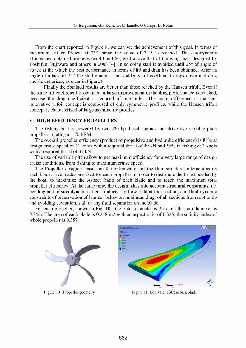
The Propeller design is based on the optimization of the fluid-structural interactions on each blade. Five blades are used for each propeller, in order to distribute the thrust needed by the boat, to maximize the Aspect Ratio of each blade and to reach the maximum total propeller efficiency. At the same time, the design takes into account structural constraints, i.e. bending and torsion dynamic effects induced by flow field at root section, and fluid dynamic constraints of preservation of laminar behavior, minimum drag, of all sections from root to tip and avoiding cavitation, stall or any fluid separation on the blade.
For each propeller, shown in Fig. 10, the outer diameter is 2 m and the hub diameter is 0.34m. The area of each blade is 0.218 m2 with an aspect ratio of 6.325, the solidity index of whole propeller is 0.357.
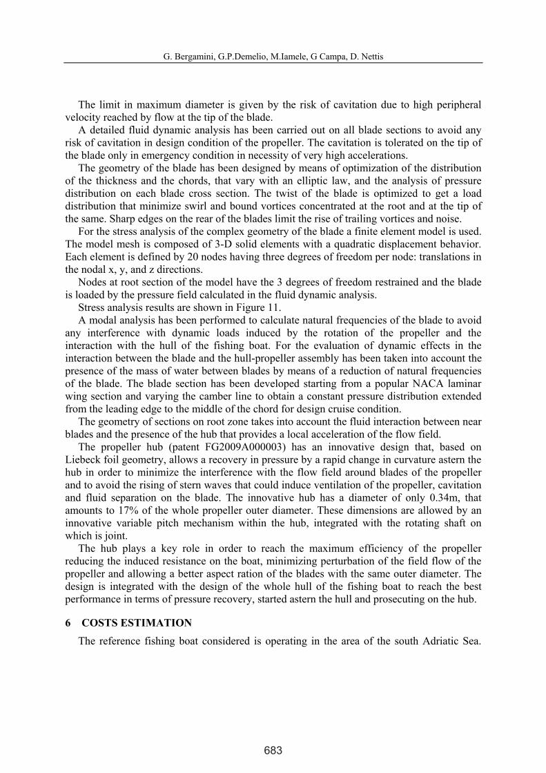
Figure 10 Propeller geometry Figure 11 Equivalent Stress on a blade
682
G. Bergamini, G.P.Demelio, M.Iamele, G Campa, D. Nettis
10
The limit in maximum diameter is given by the risk of cavitation due to high peripheral velocity reached by flow at the tip of the blade.
A detailed fluid dynamic analysis has been carried out on all blade sections to avoid any risk of cavitation in design condition of the propeller. The cavitation is tolerated on the tip of the blade only in emergency condition in necessity of very high accelerations.
The geometry of the blade has been designed by means of optimization of the distribution of the thickness and the chords, that vary with an elliptic law, and the analysis of pressure distribution on each blade cross section. The twist of the blade is optimized to get a load distribution that minimize swirl and bound vortices concentrated at the root and at the tip of the same. Sharp edges on the rear of the blades limit the rise of trailing vortices and noise.
For the stress analysis of the complex geometry of the blade a finite element model is used. The model mesh is composed of 3-D solid elements with a quadratic displacement behavior. Each element is defined by 20 nodes having three degrees of freedom per node: translations in the nodal x, y, and z directions.
Nodes at root section of the model have the 3 degrees of freedom restrained and the blade is loaded by the pressure field calculated in the fluid dynamic analysis.
Stress analysis results are shown in Figure 11. A modal analysis has been performed to calculate natural frequencies of the blade to avoid
any interference with dynamic loads induced by the rotation of the propeller and the interaction with the hull of the fishing boat. For the evaluation of dynamic effects in the interaction between the blade and the hull-propeller assembly has been taken into account the presence of the mass of water between blades by means of a reduction of natural frequencies of the blade. The blade section has been developed starting from a popular NACA laminar wing section and varying the camber line to obtain a constant pressure distribution extended from the leading edge to the middle of the chord for design cruise condition.
The geometry of sections on root zone takes into account the fluid interaction between near blades and the presence of the hub that provides a local acceleration of the flow field.
The propeller hub (patent FG2009A000003) has an innovative design that, based on Liebeck foil geometry, allows a recovery in pressure by a rapid change in curvature astern the hub in order to minimize the interference with the flow field around blades of the propeller and to avoid the rising of stern waves that could induce ventilation of the propeller, cavitation and fluid separation on the blade. The innovative hub has a diameter of only 0.34m, that amounts to 17% of the whole propeller outer diameter. These dimensions are allowed by an innovative variable pitch mechanism within the hub, integrated with the rotating shaft on which is joint.
The hub plays a key role in order to reach the maximum efficiency of the propeller reducing the induced resistance on the boat, minimizing perturbation of the field flow of the propeller and allowing a better aspect ration of the blades with the same outer diameter. The design is integrated with the design of the whole hull of the fishing boat to reach the best performance in terms of pressure recovery, started astern the hull and prosecuting on the hub.
6 COSTS ESTIMATION The reference fishing boat considered is operating in the area of the south Adriatic Sea.
683

G. Bergamini, G.P.Demelio, M.Iamele, G Campa, D. Nettis
11
The average daily activity of the boat has been determined thanks to the interview of the owner. In one day about 16 hours are scheduled for fishing at a speed of 1,5÷1,6m/s (about 3 knots). In this phase the drag of 31.000 N is distributed mainly on the cables of the nets (30.000N) and only in a small amount on the hull (1.000 N).
The information given by the owner of the boat leads to estimate a resulting oil fuel consumption of about 37,5 liters/h. The total fuel consumption is 600 liters per day.
We can deduce that, considering a net installed power of 46.500Watt (Wn =31.000x1,5=46.500Watt), and a global efficiency of the engine equal to 41%, the installed power required must be 113,415 kW.
In the daily use of the boat the time needed for reaching the fishing zone has been evaluated in 4 hours. The power required to the engine in this phase is about 75% of the maximum power, leading to a required power of 460 kW.
The net power required, due to the drag evaluated at a speed of 5.6 ms/s, is 308 kW. The global efficiency due to the propeller efficiency, to the gearbox and to the auxiliary plants is about 67%. The resulting fuel consumption, based on a specific engine consumption of 3.0 liters/kW, is 150 liter per hour. The total fuel consumption for the daily mission is therefore 1200 liters. Performing calculations on the base of 160 fishing days per year, the total amount of oil fuel is 192000 liters per year. Taking into account the cost of the oil fuel (0,66€/liter), 126.720€ per year are needed.
In order to simplify the calculations, an equivalent task of 8 hours per day is considered in reaching the fishing zone, taking into account that the new SWATH fishing boat is very efficient in the fishing phase, compared to the reference boat, and the simplified approach is therefore more conservative.
The reference speed adopted in the calculations is 7 m/s. This is the optimal speed in order to reach the fishing zone at a minimum cost. The mean Reynolds number for spindles is 6·107 The resulting Cd, evaluated according to Hoerner [3], is 0.003 and the corresponding drag is 11025 N. The evaluation of the drag due to the waves generation is based on the assumption of a Froude number 0.76 and the coefficient Cw = 0.0015, based on an extrapolation of the old data obtained by INSEAN analyses, has been applied only to the 50% of the wet surface next to the waterline. The resulting Rw is 2756 N.
Some adjustments of these results could be introduced after experimental tests to be performed at the INSEAN. The contribution due to the submerged wings Rs, whose lift is about 200.000 N, corresponds to a drag of about 4000 N, evaluated on the base of an assumed efficiency 50%, thanks to a theoretical unbounded length. The induced drag, due to the limited distance of the water line (2m) and to the leeboards, is Rd=1250 N. The contribution to the drag due to the upperworks is about 568 N. The global drag that takes into account all the above contributions is 16000 N. Therefore a net power of 112 kW is required. Considering a global efficiency of the propellers, gearboxes and auxiliary services of about 0.80%, the required global power is 140kW: The corresponding fuel consumption is 44 liters per hour.
The comparison of the oil fuel consumption, evaluated at a speed of 7 m/s for the proposed configuration, with the reference conventional fishing boat at 5.6 m/s is made assuming a quadratic relationship with the boat speed.
The resulting estimated oil fuel consumption per year is 30x160x8=38.400 liters corresponding to 25.340€/year, representing the 20% of the fuel costs estimated for the
684

G. Bergamini, G.P.Demelio, M.Iamele, G Campa, D. Nettis
12
reference conventional boat, saving 80% thanks to the contribution of the innovative hull and propellers.
If a 100 m2 wing sail is adopted, considering the average wind speed in the south Adriatic Sea, the lift under transverse wind is about 13.640 N and it could produce a 85,2% (13640/16000 = 0,853) reduction of the propulsion required by the propellers. The corresponding improvement in the propellers efficiency is not taken into account in the economic analysis performed.
In the global evaluation of the cost saving in the fishing missions, when the optimal relative wind speed is used , to get only the 59% of the above 85.2%, and so a resulting costs saving of 50%. It produces, on the basis of a cost of 25340 €/year, a cost of 12670 €/year that allows to pay in 9 years the investment related to the wing mast of about 114000 € , without considering multirole activities and related savings.
7 CONCLUSIONS The use of the wing sail could produce a substantial cut in the consumption of oil fuel, up
to 90 %, compared to the previous 80% obtained using only the optimized hull and propellers of the SWATH architecture. Moreover, there are further benefits to consider, as the better quality in the life of the fishermen and the easy recover of the investments, taking into account the numbers of other kinds of activities permitted by the innovative architecture of the boat. The prospective to recover the costs of the wing sail in less than 9 years appears realistic.
Obviously, the assumption of a more efficient reference conventional fishing boat or the introduction of worst coefficients in the calculations performed could produce a reduction of the outstanding results obtained, preserving anyway the global approach adopted in the analysis and in the possible cuts of the fishing costs.
REFERENCES [1] “Commercial History, Walker Wingsail and the MV Ashington,” available online at [http://www.cookeassociates.com/commercial.html]. Cooke states that this information is from an article in the May 1996 issue of Pacific Maritime magazine [2] Martin Rosander and Jens O.V. Bloch, Modern Windships, 2000 report. [3] Hoerner, S. F.: Fluid-Dynamic Drag. Hoerner Fluid Dynamics, Brick Town, (1965), N. J.,
USA [4] Toshifumi Fujiwara, Koichi Hirata, Michio Ueno, Tadashi Nimura, On Aerodynamic
Characteristics of a Hybrid-Sail with Square Soft Sail, Proceedings of The Thirteenth (2003) International Offshore and Polar Engineering Conference, Honolulu, Hawaii, USA, May 25–30, 2003
685