Embed Size (px)
Citation preview

Feasibility of a Small Scale Transmutation Device – Part 1 Conceptual Design onlyRoger Sit
NCHPS Meeting
Charlotte, NC
October 22-23, 2009

Outline Background Analytical Methods Conceptual Transmuter Design
Neutron Source Geometry (spherical) Reflector/multiplying material (maximize neutron flux on target) Sphere size Target size Sphere thickness (minimize sphere thickness while maximizing neutron
multiplication) Moderator material (to alter the energy spectrum) Shielding Heat Load
Conclusions

BackgroundWhat is transmutation ? The transformation of a nuclide into another
(or other) nuclide(s) Common process; albeit unwanted
Medical accelerators High energy particle accelerator Air, water, soil around accelerators and reactors
Technology using transmutation Nuclear medicine; PET/SPECT

Review of Transmutation Technologies Thermal Reactors (LWR) (to fission Pu and
transmute fission products) Fast Reactors (to fission actinides) Fusion Reactors (to fission actinides) Sub-critical reactors: Proton and electron
accelerator driven systems Lasers (g,n reactions and photofission)

Basis for Investigating the Small Scale Transmuter Concept “Small scale” means simple single radionuclide
transmutation in small quantities by a commercially available table top technology
Large scale technologies are at least a couple of decades away
Application: understand the transmutation processes in the transmuter for potential applicability to different radionuclides
Application: transmute sealed source materials recently reclaimed by the USDOE (there are thousands of these sources)

Analytical Methodology
Use a radiation transport code to model neutrons within a transmuter device to determine flux and energy spectra impinging upon a target radionuclide
Use the energy spectra to calculate radionuclide transmutation products through available processes (ie, fission; n,g; n,2n; n,p; etc)
Calculate activities, gamma dose rates, ingestion and inhalation toxicities, and cooling times for these transmutation products

Analytical Tools MCNPX for transmuter design MCNPX for kcode calculations EASY-2003 for transmutation studies; contains FISPACT,
an inventory code developed for neutron induced activation calculations over last 17 years
ICRP 72 Ingestion and inhalation DCFs MCNPX for shielding calculations NCRP 38 Neutron Fluence to DCFs (10CFR20) ICRP 51 Photon Fluence to DCFs

Preliminary Transmuter Design Basic source term Evaluate material type for best
multiplication/reflection to optimize neutron flux Evaluate optimum thickness of material Evaluate optimum size of sphere Evaluate mesh tally results inside the sphere Evaluate neutron energy spectrum inside transmuter
by using different moderators and target sizes Select transmuter base cases to carry out the
transmutation calculations

Review of Neutron Generators Accelerator–based neutron sources RF-driven plasma ion sources Pyroelectric crystal fusion Sonofusion

Neutron Source
Geometry:
26 cm diameter, 28 cm length
RF-driven plasma ion source


Reflector/Multiplying Material Considered
1020304050607080
1 2 3 4 5 6 7 8 9 10 11
Flu
x R
ati
o
Materials
Description
1. No reflector
2. 1m C
3. 5cm Be, 1m C
4. 1m Be
5. 0.5m Be, 0.5m C
6. 5cm Pb, 1m C
7. 5cm Pb, .5m Be, .5m C
8. 10cm Pb, 1m C
9. .5m Pb, .5m C
10. 1m Pb
11. 1m DU
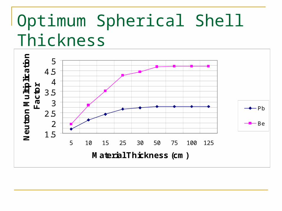
Optimum Spherical Shell Thickness
1.52
2.53
3.54
4.55
5 10 15 25 30 50 75 100 125
Material Thickness (cm)
Ne
utr
on
Mu
ltip
lica
tio
n
Fa
cto
r
Pb
Be
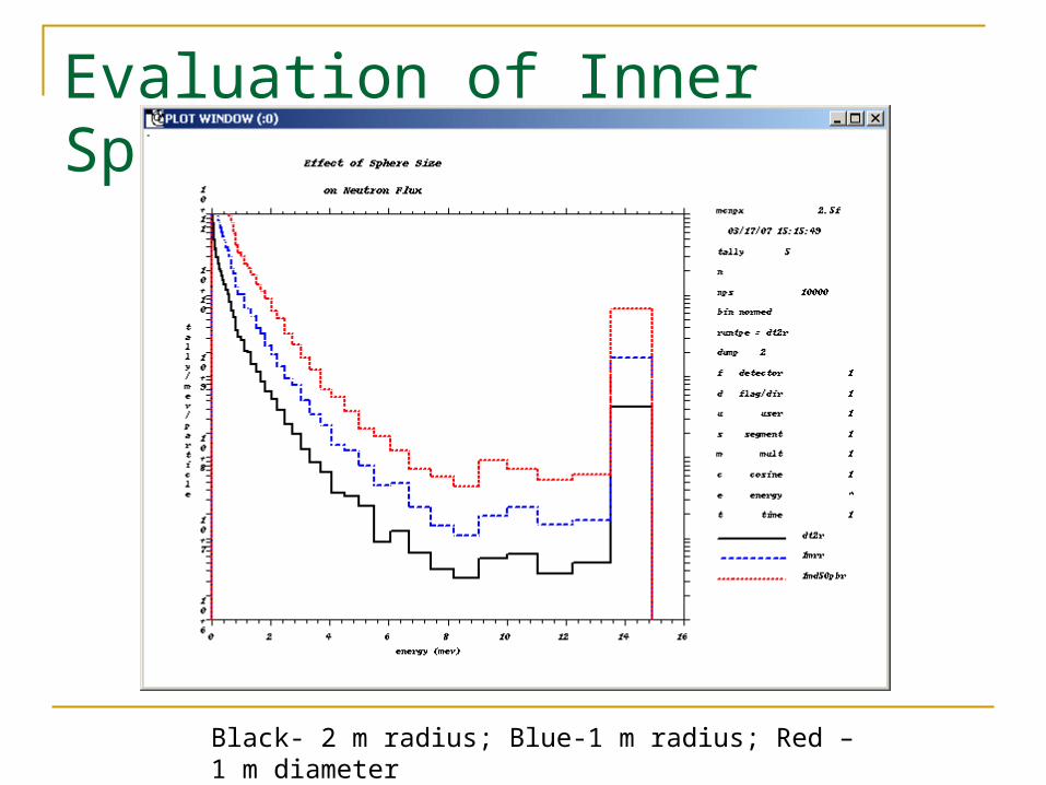
Evaluation of Inner Sphere Size
Black- 2 m radius; Blue-1 m radius; Red – 1 m diameter

Evaluation of Effect of Target Size

Neutron Flux Distribution within Sphere (n/cm2-s)

Iterate on Moderator Material for D-T Device D-T Neutron Spectra vs Materials
1.E+06
1.E+07
1.E+08
1.E+09
1.E+10
1.E+11
1.E+12
1.E-07 1.E-06 1.E-05 1.E-04 1.E-03 1.E-02 1.E-01 1.E+00 1.E+01 1.E+02
Neutron Energy (MeV)
On
-tar
get
Flu
x (n
/cm
2-s)
TLL
TWL
TTL
WWL
LTW
LLW
TTW
LLT
LLL
TTT
WWW
CFCFCF
AAA
WLLL
NNN
T:teflon, W:water, L:lead, CF:calcium flouride, A:aluminum oxide, N:nickel

Transmuter Design Base Cases D-T generator, unmoderated sphere (DT-Unmod): lead
sphere, 25 cm thick, 50 cm inner radius, neutron source strength of 3E14 n/s
D-T generator, moderated sphere (DT-Mod): Lead sphere, 25 cm thick, 5cm thick teflon, 45 cm inner radius, neutron source strength of 3E14 n/s
D-T generator, themalized sphere (DT-Thermalized): lead sphere, 25 cm thick, 50 cm inner radius filled with heavy water, neutron source strength of 3E14 n/s
D-D generator, moderated sphere: Lead sphere, 25 cm thick, 5cm thick teflon, 45 cm inner radius, neutron source strength of 1E12 n/s

DT-therm

Calculate Shielding
Use ANSI/ANS 6.6.1 concrete composition with a density of 2.3 g/cc.
Use two variance reduction techniques Geometry (splitting and Russian roulette) Source biasing
Use ICRP 51 photon DCFs Use NCRP 38 neutron DCFs


Calculate Heat Load Calculate heat load from neutron and photon energy
deposition (collision heating)in material using MCNPX Calculate heat load from activation products in material
using MCNP coupled with FISPACT (determine neutron flux impinging on the transmuter shell and the heat load from the subsequent activation products in the shell)
Convert kW to J/hr and then using specific heat capacity of lead, determine the resulting heat rise in C°/ hr.
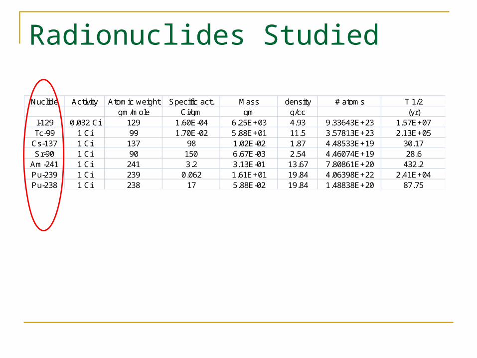
Radionuclides Studied
Nuclide Activity Atomic weight Specific act. Mass density # atoms T 1/2gm/mole Ci/gm gm g/cc (yr)
I-129 0.032 Ci 129 1.60E-04 6.25E+03 4.93 9.33643E+23 1.57E+07Tc-99 1 Ci 99 1.70E-02 5.88E+01 11.5 3.57813E+23 2.13E+05
Cs-137 1 Ci 137 98 1.02E-02 1.87 4.48533E+19 30.17Sr-90 1 Ci 90 150 6.67E-03 2.54 4.46074E+19 28.6
Am-241 1 Ci 241 3.2 3.13E-01 13.67 7.80861E+20 432.2Pu-239 1 Ci 239 0.062 1.61E+01 19.84 4.06398E+22 2.41E+04Pu-238 1 Ci 238 17 5.88E-02 19.84 1.48838E+20 87.75

Requirements for Activation Calculations Neutron flux Neutron energy spectrum Dominant reactions and the energy
thresholds for these reactions Nuclear reaction cross sections EASY-2003, European Activation System, a
software package utilizing FISPACT


Tc-99 (n,g) cross sections

Conclusions
There is no advantage to using the D-D rather than the D-T neutron generator as the neutron source . Any advantage of having a lower energy spectrum from the D-D is easily compensated by moderating or thermalizing the D-T source neutrons.
With regards to the transmuter shell, Be is a larger neutron multiplier than Pb; but not large enough to overcome the major disadvantages such as toxicity and cost
The size of the inner sphere doesn’t affect the energy distribution of the on-target neutrons much (only the flux value)
The neutron flux is fairly uniform throughout the spherical volume so target placement is not critical.
Transmuter shell optimum thickness is 25 cm. Teflon is the moderator material that gives the best combination
of both total neutron flux and lower energy neutrons.

Thank YouQuestions?
Stay tuned: transmutation results and feasibility conclusions to be presented at next meeting.