Embed Size (px)
Citation preview

FEASIBILITY AND DESIGN OF THE CLUBSTEAD: A CABLE-STAYED FLOATING STRUCTURE FOR OFFSHORE DWELLINGS
Alexia Aubault Marine Innovation & Technology
Berkeley, CA
Wendy Sitler-Roddier Marine Innovation & Technology
Berkeley, CA
Dominique Roddier Marine Innovation & Technology
Berkeley, CA
Patri Friedman The Seasteading Institute
Palo Alto, CA
Wayne Gramlich The Seasteading Institute
Palo Alto, CA ABSTRACT
The ClubStead is a novel type of offshore floating
platform, which provides comfortable and safe
ocean-going dwellings for communities of a few
hundred people. The prospect of large, unclaimed
ocean spaces has encouraged people to consider
developing sea-going settlements. A number of
attempts have been made on former oil platforms or
cruise ships. But these structures are not designed for
permanent living at sea and fall short of meeting
dwellers' expectations. Efforts to build large,
spacious floating living facilities have struggled to
balance cost-effectiveness and structural integrity.
This paper describes an innovative, cost-efficient
solution to maximize space on offshore structures. To
control the cost, the submerged volume of the floater
is minimized. To maximize comfort, the available
living surface area is also maximized, while the
motions of the platform are limited. The proposed
solution is based on the principles of tensegrity,
which are commonly used on bridges. Cable stays are
tensioned at the top of towers to support the weight
of both light and cantilevered top-sides. The floater is
column-stabilized with four submerged columns.
A feasibility study was performed for the design of a
Clubstead based off the coast of California. The
platform is dynamically positioned and can house up
to 270 people. Due to its primary function, as a
floating living facility, the architectural design and
the engineering studies are intertwined. Iterations are
necessary to determine the global characteristics of
the ClubStead. The buildings and living spaces are
arranged by an architect, within specific offshore-
related constraints. The resulting payload is
calculated and thus used in the design basis to
perform the engineering analysis. The feasibility
study focuses on survivability and passenger comfort
to assess the novel design. The survivability analysis
is based on structural strength and motion predictions
in a 100-year storm. Passenger comfort is evaluated
in operational conditions.
KEYWORDS Offshore Living Facility, Tensegrity, Column-
stabilized, Architecture, Passenger Comfort.
INTRODUCTION
The design of floating structures is shaped by their
function in the ocean space. The ocean has been
exploited mostly to meet economic necessities. Ships
are designed as means of transportation. Moored and
bottom-fixed offshore platforms have emerged as the
foundations for energy exploitation offshore.
Meanwhile, the need for viable solutions to establish
residence at sea is growing due to renewed interest in
experimenting with nation and community building
and in exploring new frontiers. But to this day, few
communities have successfully settled permanently
offshore. The principality of Sealand established on a
Proceedings of the ASME 2010 29th International Conference on Ocean, Offshore and Arctic Engineering OMAE2010
June 6-11, 2010, Shanghai, China
OMAE2010-20268
1 Copyright © 2010 by ASME
former World War II British sea fort is the most
notable example. Most other designs were derived
from cruise ships. But ships are not best suited for
permanent offshore settlements due to relatively large
roll responses in beam waves. Large semi-
submersible platforms, used in the oil and gas
industry, are more stable but costly. Alternatively,
Watanabe et al. (2004) highlight the developments of
pontoon type structures in their review of Very Large
Floating Structures. Considerable attention has been
given to the design and construction of the
MegaFloat in Japan, described by Kikutake (1998)
and Kobayashi et al. (1998). But these large
structures have small air-gap. They operate in
shielded basins or need the protection of breakwaters.
The present work introduces a new type of floating
structure intended for long-term offshore dwellings in
the open ocean. It is designed to provide a
comfortable and aesthetically pleasing environment
and to be able to handle open ocean weather. The
ClubStead is a column-stabilized platform which
relies on tensegrity to maximize its usable deck
space.
A preliminary design of a ClubStead platform is laid
out to illustrate the particular challenges of building
offshore dwellings. Due to the importance of living
spaces aboard and of integrating business and
residential functions together, an architectural plan
must be drawn early in the design. It must take into
account the engineering constraints of offshore
reliability. Conversely, the engineering analysis
incorporates the preliminary architectural plan in its
design basis. A methodology is developed to ensure
the convergence of both the architectural and the
engineering design. The viability of the concept is
demonstrated herein with the design and analysis of a
ClubStead for 270 people. The platform is assumed
dynamically positioned 100 miles off the coast of San
Diego, California. The dynamically-positioning
system provides more flexibility to avoid potentially
harmful storms, while removing potential permitting
issues due to mooring interactions on the seabed.
A NOVEL DESIGN: FLOATING TENSEGRITY FOR OFFSHORE DWELLINGS
Before the initial concept was developed, the basic
needs of the residents were identified. They fall into
four categories:
Autonomy of the Clubstead: the platform should
be economically sustainable. Hence, the structure
is designed to house business spaces. Business
functions are embedded in the organization of
the structure. A few alternatives are considered in
the first phases of design. In one instance, the
platform is arranged to include touristic facilities,
with a casino and an offshore resort. In another
example, the community could be focused on
providing medical services.
Passenger comfort. This is an essential feature of
the platform. Life at sea can be harsh due to
special restrictions and constant motions. The
ClubStead needs to be spacious enough to
provide sufficient living areas for its dwellers.
The probability of sea-sickness must also be
minimized to optimize passenger comfort.
Passenger safety is critical for an ocean going
vessel with passengers. To ensure the reliability
of the structure in harsh ocean weather, the
ClubStead is designed to survive a 100 year sea-
state on site. Additionally, fire fighting and
medical equipment and emergency evacuation
plans are included into the building plans.
Cost optimization of the project is a major
condition to its feasibility. In the preliminary
phase, it consists in minimizing the displacement
of the platform. It can also be enhanced by
planning for all phases of construction and
installation.
A large floating structure must develop sufficient
hydro-elastic strength to support the loading of large
low-frequency water waves. Attempts with pontoon-
type structures like the Mega-Float are limited to
coastal areas and remain difficult to scale to open
ocean operations. An alternative approach consists in
raising the deck high enough above the waterline to
protect it from direct wave interaction. This solution
is applied on column stabilized platforms in the oil
and gas industry. But the span between columns
cannot be expanded in a cost effective manner and
decks are typically shorter than 100 m.
The concept of the ClubStead draws on technological
developments in bridge engineering during the 20th
century. As span length increased, the cost efficiency
of cantilevered bridges diminished and they were
slowly replaced by lighter alternatives involving
cable support. Cable stayed bridges benefited from
improvements in cable connection and material in the
second part of the 20th
century and are now spread
worldwide. Increasing the length of the deck on a
floating structure may be compared to the
lengthening of the span on cantilevered bridges.
On the ClubStead, semisubmersible technology is
employed for adequate sea-keeping characteristics.
To minimize the displacement while preserving
sufficient stability, a column stabilized design is
chosen. A footing at the base of the column lowers
the center of gravity and increases the natural heave
2 Copyright © 2010 by ASME

period for maximum stability of the platform in
waves.
An extension of the deck beyond the column-
enclosed space is achieved. The innovation resides in
the addition of cable-stayed deck structures which do
not need to be supported at both ends by a floating
component. Support for the extended deck is
provided by stay cables. The cables transfer the dead
loads as compression to the top of the towers, above
the columns. The use of such technology at sea is
made possible by developments in anti corrosion
systems for high-stress steel cables and the rise of
carbon fiber cables as described by Meier (1992).
Figure 1: Representation of the ClubStead concept -
columns and footings in red, deck structure in grey
The deck structure is a combination of three
structural components as illustrated in Figure 1:
- Between columns, a large truss provides
sufficient lateral stiffness to the platform and is also
used to support heavy buildings
- On the extended deck, buildings may be
supported. For these heavy deck structures, a light
cantilevered truss is seconded by cable stays,
- Light deck surface areas on the extended
deck and at the center of the platform are intended for
recreational use. They are cable stayed.
Additional cables can be used below deck to counter
the dynamic effects of wave induced motions on the
suspended structures. The use of a horizontal cable
between columns was also considered to enhance
lateral stiffness.
AN ITERATIVE DESIGN APPROACH The ClubStead is designed according to the offshore
industry standards for passenger vessels and semi-
submersible vessels. The following design codes are
used for the hull and safety design:
- American Bureau of Shipping (ABS) Rules for
Building and Classing Mobile Offshore Drilling
Units, 2006
- American Petroleum Institute (API):
• API RP 2SK, Recommended Practice for
Design and Analysis of Stationkeeping Systems for
Floating Structures, 2005
• API RP 2A-WSD Recommended Practice
for Planning, Designing and Constructing Fixed
Offshore Platforms - Working Stress Design, 22nd ed
- International Maritime Organization (IMO)
International Convention for the Safety of Life at Sea
(SOLAS), 1974
The design of the ClubStead is carried out iteratively.
The design process is illustrated in Figure 2. After
formulation of the conceptual idea, a design basis is
written for a specific project. It provides the function,
occupancy and location of the platform. The
metocean conditions can be derived from archived
environmental data measured at NOAA buoy 46047
which is located close to the chosen San Diego site.
Figure 2: Iterative Design Process of ClubStead
A preliminary sizing is performed to meet basic
requirements in hydrostatics and hydrodynamics.
This phase determines the global dimensions of the
platform, such as the column span and overall deck
dimensions. These values are carried on to the next
stage, which iterates between the architectural design
and the structural sizing of the deck to determine the
best use of deck space. The structural designer
provides the architect with the deck space distribution
by defining the areas available for buildings and
those reserved for light spaces. The architect in turn
lays out the buildings and provides the structural
engineer with the dead loads on the deck. Both
structural and architectural designs are translated into
global mass properties and wind properties to
perform the hydrodynamic analysis
Light surface
Main truss
Cantilevered
building
Footings
3 Copyright © 2010 by ASME

The hydrodynamic analysis focuses on the rigid body
response of the platform. It ensures that the motions
are within acceptable limits in the given metocean
conditions. To compute the time domain response of
the ClubStead, hydrodynamic program TimeFloat is
used. It is a 6-degree-of-freedom fully coupled
hydrodynamic program which was developed to
analyze the motions of floaters subject to
environmental loads, non linear viscous loads due to
shedding, mooring forces and any other mechanical
forces. The program was described by Cermelli et al.
(2004) and (2008). It uses diffraction-radiation
software WAMIT as a pre-processor to obtain
hydrodynamic coefficients and first order forces.
These forces are converted in the time-domain by use
of a Jonswap wave spectrum. Viscous and current
forces are included in the equations with a Morison
formulation. Wind forces are based on wind
coefficients combined with an API wave spectrum.
The wind coefficients on the ClubStead are generated
for any directions based on a drag coefficient of 1.
The DP system is modeled with a linear force using
soft horizontal springs which are set up at the
potential location of the thrusters, 10ft under the
waterline to control the motions in surge, sway and
yaw. The location of the thrusters should be
confirmed in further design stages.
At the end of the hydrodynamic analysis, additional
iterations of the structural and architectural design
may be necessary to adjust the center of gravity or
the wind area.
Eventually, the design process converges toward a
solution and the fulfillment of basic requirements is
verified. The operability of the design is judged by
the degree of autonomy and the level of comfort
aboard the platform. Its reliability is estimated based
on the survivability criteria. If the global dimensions
are such that the design is not satisfying at this stage,
they should be revised and the process should be
reiterated. When a solution appears, the consistence
of the initial global dimensions with the mass
properties is checked and additional iterations are run
if necessary. The present paper does not describe the
details of design iterations on the ClubStead. It
focuses instead on the assessment of operatibility and
survivability of the final design.
GLOBAL SIZING The global dimensions of the ClubStead at the end of
the iterative design process are summarized in Table
1. The dimensions on the deck are illustrated in
Figure 3.
Table 1: Global Dimensions of ClubStead (in ft)
COLUMNS
Column diameter 41
Footing Diameter 76
Footing Height 20
Draft 75
Air-gap 40
DECK
Span between columns 200
Length of horizontal extension
beyond column 100
Width of a building 50
Figure 3: Dimensions of ClubStead (in ft)
The payload represents more than 30% of the
displacement, in Table 2. This high ratio is made
possible by the overall stability of the platform.
In the final architectural layout, a total of 368,200 ft2
is available for passenger use on the ClubStead,
including 90,000 ft2 of open recreational surfaces. It
does not include the machinery and maintenance
areas. Based on an estimated 50 lb/ft2 for buildings
and 30 lb/ft2 for open areas, the total payload is 7,705
st.
An estimated 2619 st of primary deck steel is
necessary to support this payload.
The wind projected surface area is 41,680 ft2 and the
center of pressure is located 79.6ft above the mean
waterline.
In operations, the metacentric height (GM) is 13.8ft.
The heave natural period of the ClubStead is 17
seconds.
100.00
4 Copyright © 2010 by ASME

Table 2: Weight summary of the ClubStead (in short
ton)
Structure:
Hull steel 4386
Primary Deck steel 2619
Appurtenances 10
Total structure 7016
Payload:
Machinery 414
Living Areas + Open areas 7705
Total 8118
Live loads (residents, diesel):
Total 575
Ballast:
Total 5200
Total weight: 20908
Mass properties for the hydrodynamic analysis are
summarized in Table 3.
Table 3: Global mass properties of ClubStead after
iterations on the structural and architectural design
Description unit
Total Weight 20,908 st
Center of gravity above
the mean waterline 19.5 ft
Radius of Gyration Rx 87.5 ft
Radius of Gyration Ry 87.5 ft
Radius of Gyration Rz 112.4 ft
PASSENGER COMFORT IN OPERATIONS The comfort level aboard the ClubStead must be
maximized during operational conditions. Passenger
comfort is attained through architectural features and
motion control. The architectural layout of the living
spaces on the deck must be attractive and spacious.
The following section describes how the architectural
program of the ClubStead accommodates the
necessities of an offshore design in a spacious
environment. Additionally, passenger discomfort due
to wave-induced motions of the platform should be
minimized. This is verified by calculating the
response of the platform in operational sea states.
Architecture The initial program for the platform was an offshore
resort with a luxury hotel and club casino intended to
accommodate up to 270 people at a time. Although
this first conceptual design was charged with spaces
rendered for the hospitality program, the design of
the platform and the conceptual form of the
architecture can be used for a variety of business and
residential functions. The flexibility is inherent to the
form of the architecture.
The use of the available surface area of the platform
must be optimized and the architecture must provide
a sense of openness and space comparable to that of
an onshore resort. It should feel more spacious than a
typical cruise ship.
The architectural program takes into account a
number of constraints. The layout of the architecture
is driven by engineering considerations: the allocated
area of the platform is limited to a 400’-0” x 400’-0”
square deck surface; the maximum structural support
for the architecture is provided on a 40ft wide strip
between columns located 200’-0” apart from each
other in plan.
Figure 4: Top View of ClubStead Architectural Plan
The buildings are organized around the four main
structural columns. The cruciform plan of the
architecture at each column is supported by the
primary 40’-0” box trusses described in the structural
analysis. A pyramidal form at each column was
adopted to provide maximum spatial openness. It also
keeps the center of gravity low, by minimizing the
weight at the upper levels of the buildings. A low
center of gravity is critical to the stability of the
platform.
Three of the four columns are dedicated to the
program of the hotel for hotel rooms, staff quarters,
function spaces, restaurants and bars and spa and
fitness areas. The fourth column is a mechanical
tower that houses the equipment and spaces needed
for operations of the building and for life at sea. A
club casino, or a large community space, is located
5 Copyright © 2010 by ASME
near the mechanical tower and separated by sound
and safety isolation walls.
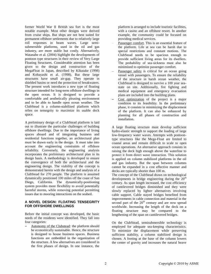
Figure 5: General Perspective View of ClubStead Arc-
hitectural Design
The hotel buildings have seven floors of interior
spaces. The first floor houses a hotel lobby and back
of house service spaces, retail spaces, restaurants, the
spa and fitness amenities and public circulation. The
second floor houses the staff quarters, function and
meeting spaces along with additional spa and fitness
level spaces. There are four levels of rooms above
level two. The use of space is optimized by
integrating rooftops into functional areas. The
seventh level, or rooftop level, houses restaurant
terraces and rooftop lounges. Vertical circulation of
elevator and stairs for each tower are located inside
the columns. There are also enclosed walkways at
levels 2, 3 and 4 to provide cross-tower access.
Figure 6: View onto a rooftop lounge on ClubStead
At the deck level, light-weight surface areas at the
platform perimeter and center are suspended off the
columns with cable stays; they provide recreational
space for gardens, tennis courts, exterior dining areas,
lookout points, etc.
Safety and maintenance spaces are reserved to meet
the requirements of life at sea. A column is assigned
to machinery. For the community to be autonomous,
fresh water may be made aboard from sea water. A
recycling center and a water and sewage treatment
center provide maximum autonomy over waste
management. A combination of diesel engines and
solar panels will ensure the energy supply for utility
and propulsion of the dynamically-positioned system.
Additionally, the platform is equipped with safety
equipments according to recommendations from the
International Convention for the Safety of Life at Sea
(SOLAS) organized by the IMO (International
Maritime organization) in 1974 [1]. The architectural
program makes room for a control room and safety
center, a fire-fighting room and multiple fire stations,
and a medical center. For easy access and evacuation,
a boat landing and two helipads are included in the
plan. Sufficient life-saving equipment is provided in
accessible areas.
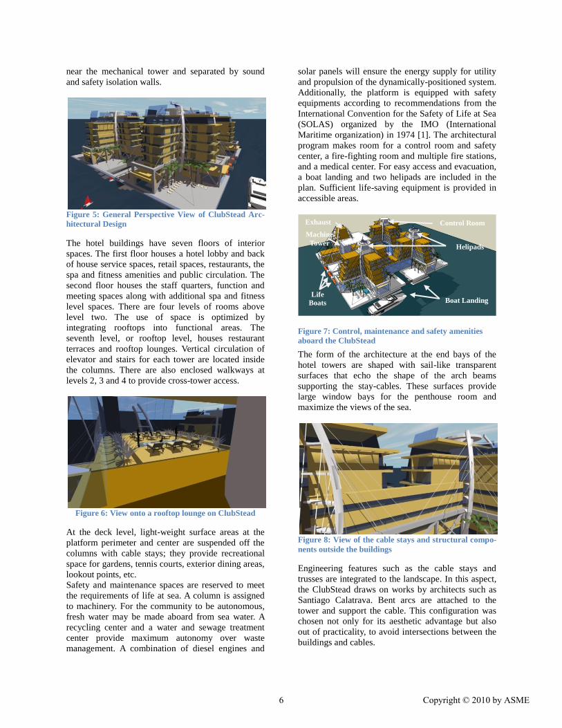
The form of the architecture at the end bays of the
hotel towers are shaped with sail-like transparent
surfaces that echo the shape of the arch beams
supporting the stay-cables. These surfaces provide
large window bays for the penthouse room and
maximize the views of the sea.
Figure 8: View of the cable stays and structural compo-
nents outside the buildings
Engineering features such as the cable stays and
trusses are integrated to the landscape. In this aspect,
the ClubStead draws on works by architects such as
Santiago Calatrava. Bent arcs are attached to the
tower and support the cable. This configuration was
chosen not only for its aesthetic advantage but also
out of practicality, to avoid intersections between the
buildings and cables.
Boat Landing Life
Boats
on both
sides of
platfor
m
Control Room
Helipads
Exhaust
Machine
Tower
Figure 7: Control, maintenance and safety amenities
aboard the ClubStead
6 Copyright © 2010 by ASME

Relative Motions in Operations Research by O’Hanlon and McCauley (1974) has
shown that the fraction of people who become sick
onboard a vessel is a function of acceleration,
excitation frequency and duration of exposure. The
International Standard ISO 2631 states that, at typical
wave peak frequencies, a majority of the passengers
is seasick after being exposed to a vertical
acceleration RMS of 0.25m/s2 for 8 consecutive
hours.
The 8-hour exposure curve is used to assess the level
of comfort aboard the ClubStead. The RMS of heave,
roll and pitch induced vertical acceleration is
computed over 1-hour TimeFloat simulations for all
sea-states in the wave scatter diagram. The
environmental conditions are derived from 10 years
of NOAA data. The waves at 0 degree heading are
combined with the most probable 1-hour mean wind
velocity at the given significant wave height. The
vertical acceleration is computed at the locations
represented in Figure 9.
Probabilities of exceedence are calculated based on
the probability of occurrence of the sea-state:
iseastate
aRMSi ipaRMSP )( (1)
where pi is the probability of occurrence of sea-state i
and RMS>a is equal to 1 when the RMS of
acceleration at the given sea-state is greater than a
and 0 otherwise. Results are provided at chosen
locations for a=0.1 m/s-2
and a=0.25m/s-2
in Table 4.
The distribution of acceleration RMS is plotted in
Figure 10.
Table 4: Probability of Exceedence of Vertical Accelera-
tion RMS
Probability of Occurrence (%) of Vertical
Acceleration RMS > than
Position 0.1 m/s2 0.25m/s2
Center of deck 43 1.3
Extremity of Deck 2 65 1.5
Extremity of Deck 3 72 5.4
Top of Tower 4 48 1.3
Figure 10: Probability of occurrence of level of vertical
acceleration aboard the ClubStead
The NORDFORSK project (1987) published criteria
per type of vessel and activities. It states a line cruiser
should offer maximum comfort among ships with an
acceleration RMS below 0.02g (0.2m/s-2
). This level
of comfort is attained between 90 and 97% of the
time on the ClubStead.
Figure 11: RMS of vertical acceleration - center of deck
(position 1)
Figure 1: Probability of Occurrence of Vertical Acceleration RMS Values
05
101520253035404550
Pro
ba
bil
ity
of
Occu
ren
ce
(%
)
Location #1
Location #2
Location #3
Location #4
Location #5
4 6 8 10 12 14 16 18 20 0
0.05
0.1
0.15
0.2
0.25
0.3
0.35
0.4
Period (sec)
Heave RMS (m/s-2)
ISO limit T = 12.5s Hs = 1m = 3.3ft Hs = 2m = 6.6ft Hs = 3m = 9.8ft Hs = 4m = 13.1ft Hs = 5m = 16.4ft Hs = 6m = 19.7ft
8 hour exposure Figure 9: Locations to Compute Vertical Acceleration
#3
#4
#1
#2
#5
Wave Direction
7 Copyright © 2010 by ASME

Figure 12: RMS of vertical acceleration - extremity of
deck (position 3)
Long period waves, with peak periods larger than 10
seconds, are frequent at the San Diego site. Passenger
comfort could be further improved by increasing the
heave natural period. It is illustrated in Figure 11 and
Figure 12 which represent the vertical acceleration
RMS as a function of peak period Tp for significant
wave heights Hs between 1 and 6m. Discomfort
increases with Hs but the wave period has the most
significant effect. The discomfort level peaks at the
heave period of resonance of the platform, around 17
seconds. Notably, the discomfort level increases also
on the extremities of the platform for Tp=12.5sec.
This is consistent with the increase in pitch and roll
RAO at this period.
RELIABILITY IN SURVIVAL CONDITIONS According to API recommendations, the ClubStead is
designed to survive the loadings and motions in a 1-
year, 10-year and 100-year return storm at the
intended site. A Weibull fit on the historical data
provides the most probable extreme sea-states
described in Table 5.
Table 5: Extreme Sea States off San Diego, CA
Return Period 1 year 10 year 100 year
Hs m 7.0 7.7 8.3
Tp s 14.3 14.3 14.3
Wind Speed m/s 16.0 17.5 18.9
Current Speed m/s 0.48 0.53 0.57
The survivability criteria of the ClubStead are
defined as follows:
- The structural integrity of the platform is not
affected by extreme wave and wind
loadings.
- Green water remains clear of the deck, with
a minimum clearance of 5ft.
- Maximum pitch and roll angle do not exceed
10 degrees.
These conditions are based on typically
recommended practice for offshore structures.
Structural and hydrodynamic analyses are carried out
to ensure that the dimensions and characteristics of
the ClubStead are sufficient to fulfill the criteria.
Structural integrity The preliminary structural analysis aims at estimating
the amount of steel to build the ClubStead. This is
necessary to obtain the mass properties for the
hydrodynamic analysis. It is also used to derive a
preliminary cost estimate of the platform.
The main structural components of the ClubStead
are:
- The four columns and footings, which will
be compartmented and stiffened according to
offshore industry standards, such as the ABS MODU
rules. These are common elements on semi-
submersible hulls. In this preliminary analysis, the
steel density is assumed equal to 8lb/ft3, which was
determined sufficient for a semi-submersible of
similar draft by Aubault et al (2009).
- The deck primary structure consists of the
main truss which supports the wave loads and the
dead loads of the buildings between columns; the
secondary truss which supports the cantilevered areas
with buildings; and the simple beams to help
maintain the cable stayed light-weight surfaces. The
sizing of these beams and trusses is carried out using
a finite element analysis. It is described herein.
- The towers and cable supporting arcs, on top
of the columns, are designed to withstand the
compression and bending moment from the cable
tension. These internal forces are computed with the
same finite element model.
The truss and beams consist of tubular members. The
design of the deck primary structure is based on API
Recommended Practice 2A - Working Stress Design.
The feasibility study focuses on the strength analysis
to provide an estimate of primary steel weight. A
fatigue analysis on the truss connections should be
performed in further stages. The overall structural
integrity of a member is assessed by computing
combined axial and bending stress ratios. All
computed ratios must be less than 1.0 to comply with
API RP2A-WSD.
A finite-element model is built in finite element
program SAP2000 version 12. The primary structure
4 6 8 10 12 14 16 18 20 0
0.05
0.1
0.15
0.2
0.25
0.3
0.35
0.4
Period (sec)
Heave RMS (m/s2) ISO 8 hour limit T = 12.5 sec Hs = 1m = 3.3ft Hs = 2m = 6.6ft Hs = 3m = 9.8ft Hs = 4m = 13.1ft Hs = 5m = 16.4ft Hs = 6m = 19.7ft
8 Copyright © 2010 by ASME

of the ClubStead is analyzed within the framework of
beam theory. A static analysis is run to determine the
internal forces in the deck primary structure, starting
with small tubular sizes on the trusses and beams.
Cables are included as tendon elements with a given
pretension to model the effect of stay cables on
suspended surfaces. The detailed analysis of the cable
subject to dynamic excitations is out of the scope of
this study. A damping system may be necessary to
counter the dynamic effects of wind and wave loads.
This will be addressed in later design stages.
Figure 13: Finite Element model of the ClubStead in
SAP 2000 v12
Applied loads on the platform include:
- Dead loads:
The weight of the buildings on the primary deck
structure is applied by assigning distributed loads on
surface areas. The self-weight of the steel frame ele-
ments is added automatically.
- Wave loads:
The wave force acting on the submerged frame ele-
ment is calculated using a Morison formulation,
based on a linear Airy wave potential. The most ex-
treme wave loads are associated with the squeezing
and prying modes at 0 and 45 degree heading waves,
as illustrated in Figure 14. The characteristics of the
design waves are summarized in Table 6. Wave
heights were chosen to provide conservative results.
The wave periods are calculated based on deep water
theory. Buoyant forces are also included.
Table 6: Characteristics of Airy Waves used to size the
ClubStead primary structure
Wave
#
Wave
length
(ft)
Wave
Direction
(deg)
Wave
Period
(sec)
Wave
Height
(ft)
1 565.7 45.0 10.5 40
2 282.8 45.0 7.4 35
3 400.0 0.0 8.8 35
Figure 14: Squeezing and Prying modes of extreme
wave loads
- Wind loads, propulsion loads and secondary
forces are neglected in this preliminary analysis.
Wind vibration on the deck should be the object of a
detailed analysis.
The static analysis is iterated until an appropriate
design is found. At first, only the main trusses are
included to ensure they are designed to support the
wave loads alone. Main trusses are 40ftx40ftx150ft
truss boxes. They have three bays with large
horizontal pipes to resist the wave loads. Diagonal
beams provide additional support. Eventually the
cantilevered trusses and light-weight areas are added
with their supporting cables. Several iterations are
necessary to determine the most appropriate
configuration of the trusses and cable layout. The
final finite element model is represented in Figure 13.
Other configurations were considered to provide
lateral support to the main truss. For instance, a small
pontoon or bracing between the keels would reduce
lateral loads at the deck level.
Extreme Motions in Storms The rigid body motions of the platform are computed
for 3-hour simulations of the 1 year, 10-year and 100-
year storms, with time-domain hydrodynamic
program TimeFloat.
Figure 15: Wave gage position on ClubStead to compute
green water level
1
4
5 6 3
2
W
A
V
E
0°
heading
wave
45°
heading
wave
9 Copyright © 2010 by ASME

To verify that the deck remains clear of the wave
crest throughout extreme weather conditions, time
series of relative positions of the deck and wave crest
are calculated at several critical locations. The
position of six such “wave gages” is represented in
Figure 15 with a red dot.
The statistics of motions are computed over each
three-hour simulation. Results are provided in Table 7
and Table 8 for the 100 year return storm in two wave
directions.
Table 7: Statistics of motions (in ft and deg) and of wave
gage position above crest (in ft) in a 0 degree heading
100 year return storm
100 year - 0 deg Mean RMS Max Min Wave height 0.11 6.79 27.34 -28.96
Motions surge 48.36 5.73 76.18 32.36
sway 0.42 0.05 0.69 0.30
heave -0.01 6.42 19.56 -19.86
roll -0.03 0.05 0.13 -0.20
pitch 1.76 0.97 5.45 -3.10
yaw -0.56 0.10 -0.26 -0.98
Wave Gages
1 53.19 8.47 85.31 22.79
2 52.97 8.44 85.56 23.07
3 40.97 7.55 64.86 13.70
4 40.75 7.57 65.30 12.65
5 33.79 7.56 58.17 5.83
6 33.93 7.55 57.90 6.49 Table 8: Statistics of motions (in ft and deg) and of wave
gage position above crest (in ft) in a 45 degree heading
100 year return storm
100 year - 45 deg Mean RMS Max Min
Wave height 0.16 6.79 27.21 -28.71
Motions surge 37.24 3.98 58.56 25.87
sway 35.83 3.94 56.13 24.47
heave 0.00 6.40 19.38 -20.08
roll -1.18 0.68 2.30 -3.70
pitch 1.30 0.67 3.90 -2.17
yaw 2.40 0.12 3.20 1.92
Wave Gages
1 55.66 8.66 86.55 27.25
2 47.28 8.96 79.40 16.54
3 46.48 8.85 76.14 17.05
4 38.40 8.15 66.84 9.35
5 32.92 7.59 58.25 6.08
6 37.96 8.50 66.17 10.87
The minimum clearance between the deck and the
wave crest is 5.83ft. The maximum pitch and roll
angle is 5.45 degrees.
This analysis proves the reliability of the ClubStead
in extreme conditions. Empirical data is necessary to
ascertain parameters used in the numerical model.
Numerical modeling of 1st order wave motions is
highly accurate, but drag coefficients and air-gap are
best determined with model testing.
CONCLUSION The conceptual idea of the Clubstead is founded on
semisubmersible hull technology combined with
cable stays to extend the deck surface area. This
floating structure offers a maximized deck space on
an ocean-going platform. The use of cable stays
minimizes the payload, hence the displacement and
results in a cost effective solution. Static and dynamic
stabilities are provided by a column stabilized plan
with large footings. A design was presented above for
a tentative community of 270 people living in the
Pacific Ocean off the coast of California. It illustrates
the complex process entailed in the design of a cable-
stayed floating platform for permanent offshore
residences. The importance of involving an architect
early in the design process is highlighted. Interactions
between the architectural and engineering teams are
essential. They ensure the living facilities are both
comfortable and reliable. They also help identify cost
saving opportunities associated with the relative
position of structural components and architectural
features. The structural skeleton of the deck on a
floating city has the double function of supporting
dead weight, like an onshore structure, and providing
lateral stiffness to resist environmental loadings. This
must be taken into account in the architectural layout.
An iterative process ensures that the platform is
optimized within its design basis. The ideal
ClubStead provides maximized comfort and
autonomy onboard for an acceptable level of safety in
the most cost efficient manner.
Further work is needed to determine how to properly
adapt stay cable technology to floating platforms. The
effect of wind and wave dynamics on the cable
loadings must be assessed. Connectors may need
some additional damping systems. This will be best
determined with further static and dynamic structural
analysis of the system. An extensive fatigue analysis
of the cables and truss connections should be
performed in later stages. In the swell dominated
environment of the Pacific coast, fatigue is likely to
be a significant factor in the structural design.
Additionally, corrosion control of the structure and
cables should be planned for, using cathodic
10 Copyright © 2010 by ASME

protection and non-corroding materials for instance.
To validate the air-gap calculations in a 100 year
storm, the platform should be tested experimentally.
Model tests remain an important step to qualify
offshore structures and validate numerical results.
AKNOWLEDGEMENTS This work was enabled by the financial support of
The Seasteading Institute.
REFERENCES
[1]. Kikutake T., A Mega-Float Airport, the State of
the Art, Proceedings of the 17th
Intl. Conference
on Offshore Mechanics and Arctic Engineering,
OMAE 1998
[2]. Kobayashi K., Ohkawa Y., Futami Y., Large
Scale On-Sea Experiment of Mega-Float
Structures, Proceedings of the 17th
Intl.
Conference on Offshore Mechanics and Arctic
Engineering, OMAE 1998
[3]. Watanabe, E., Utsunomiya, T. and Wang, C.M,
“Hydroelastic analysis of pontoon type VLFS: A
literature survey,” Engineering Structures, 26(2),
245-256, 2004
[4]. Walther, R., Cable Stayed Bridges, Thomas
Telford Publishing, 1999
[5]. Meier, U., Carbon Fiber Reinforced Polymers:
Modern Materials in Bridge Engineering,
Structural Engineering International, Vol.2
No.1, 1992
[6]. Cermelli C.A., Roddier D.G., Aubault A.,
“WindFloat, a Floating Foundation for Offshore
Wind Turbines: Hydrodynamic Analysis”,
OMAE 2009, Honolulu, HI, USA
[7]. Cermelli, C.A., Roddier D.G., and Busso, C.C.,
“MINIFLOAT: A Novel Concept of Minimal
Floating Platform for Marginal Fields
Development”, Proc. of 14th Intl. Offshore and
Polar Engrg Conf (ISOPE), Toulon, France,
2004
[8]. Tzonis, A., Santiago Calatrava: Complete
Works, New York, Rizolis, 2004
[9]. O’Hanlon, J.P. and McCauley, M.E., 1974,
“Motion Sickness Incidence as a Function of the
Frequency and Acceleration of Vertical
Sinusoidal Motion”, Aerospace Medicine,
45(4):366-369.
[10]. International Organization for
Standardization, Specification 2631-1:1997,
Mechanical vibration and shock – Evaluation of
human exposure to whole-body vibration – Part
1: General requirements
[11]. NORDFORSK 1987 The Nordic Coopera-
tive Project for Seakeeping Performance of
Ships, Assessment of a ship performance in a
seaway, MARINTEK. (Cited within Faltinsen
1990).
[12]. Aubault A., Cermelli C.A., Roddier D.G.,
“WindFloat, a Floating Foundation for Offshore
Wind Turbines: Structural Analysis”, OMAE
2009, Honolulu, HI, USA
11 Copyright © 2010 by ASME


![[TECH]Cable Stayed Bridges](https://img.pdfslide.us/doc/110x75/544cd985b1af9f3a0b8b4c5b/techcable-stayed-bridges.jpg)