Embed Size (px)
Citation preview

8/8/2019 Fea Simplified Theory
http://slidepdf.com/reader/full/fea-simplified-theory 1/44
Practical FEA
Introduction

8/8/2019 Fea Simplified Theory
http://slidepdf.com/reader/full/fea-simplified-theory 2/44
Overview
• What is a Finite Element?
• Common terminology• Elements
• Constraints
• Loads
• Analysis types
• Units• Example model
• What’s coming..

8/8/2019 Fea Simplified Theory
http://slidepdf.com/reader/full/fea-simplified-theory 3/44

8/8/2019 Fea Simplified Theory
http://slidepdf.com/reader/full/fea-simplified-theory 4/44
What is a Finite Element?
• A continuous structure has theoretically an infinite number of
degrees of freedom
• The finite element method approximates the behaviour of acontinuous structure with a finite number of grid points (degrees offreedom)
• In essence, the finite element method is a piecewise approximation
of a function, by means of polynomials, each defined over a smallregion (element) and expressed in terms of the nodal values of thefunction.
– It interpolates displacements of points in space to get displacementsanywhere in the domain of the element.
• Because of the nature of the interpolation functions, the gradient ofthe displacement field is continuous, meaning that a continuousstrain field is implied.

8/8/2019 Fea Simplified Theory
http://slidepdf.com/reader/full/fea-simplified-theory 5/44
• In other words, the strain field in an element is continuous. This
indirectly means that the stress field is continuous in an element
• Elements next to each other do not share any information abouttheir interpolation methods, so the strain, and therefore stress fieldat element boundaries are almost always discontinuous
What is a Finite Element?

8/8/2019 Fea Simplified Theory
http://slidepdf.com/reader/full/fea-simplified-theory 6/44
• In a typical first-order quad-element, strain can vary linearly across
an element.
• This capability is used to model more complex stress fields by usinga series of linear approximations to model a nonlinear stress-field. Ingeneral, the more elements, the better the approximation
What is a Finite Element?

8/8/2019 Fea Simplified Theory
http://slidepdf.com/reader/full/fea-simplified-theory 7/44
• It’s already said that the stresses across element boundaries are not
continuous. What now? – We simply average the values at the nodes.
• Isn’t this dangerous?
– Yes it is: If the mesh is not fine enough to accurately represent thestress state.
• The error at the nodes can however also be used to check forconvergence of the mesh:
– A small error (i.e.. (max predicted) – (min predicted) ) gives a goodindication that the mesh has converged.
What is a Finite Element?

8/8/2019 Fea Simplified Theory
http://slidepdf.com/reader/full/fea-simplified-theory 8/44
What is a Finite Element?
• This brings us to one of the most important concepts in Finite Elements:Mesh Convergence
– A mesh is converged if it is able to represent the stress-state of a componentwith the required level of accuracy.
– Mesh Convergence has absolutely nothing to do with convergence settings inNon-linear analysis! Both are needed for Non-linear analysis, while only Mesh
convergence are required for linear analysis
• A linear analysis has a linear relationship between forces, displacementsand stresses.
• A nonlinear analysis has a nonlinear relationship between forces anddisplacements due to nonlinear material properties, large rotations, loadschanging as the structure deforms or if boundary conditions are dependenton displacements. Convergence for a non-linear analysis has to do with thedifference between the applied load and the reaction-forces generated bythe elements.

8/8/2019 Fea Simplified Theory
http://slidepdf.com/reader/full/fea-simplified-theory 9/44
Concept of Finite Elements
Physically the finite element method is the subdivision of the model
into discrete components of simple geometry called finite elements.(discretization)

8/8/2019 Fea Simplified Theory
http://slidepdf.com/reader/full/fea-simplified-theory 10/44
Common Terminology
• Node: A point in space that is used to connect the elements to.
– Loads / Boundary conditions can only be applied to nodes. Evenpressure values or gravitational loads are reduced to loads at nodes bythe finite element solver.
• DOF (Degree of Freedom): This is the displacement of a Node
– Three translations (ux
,uy
,uz
)
– Three rotations (θx, θy, θz)

8/8/2019 Fea Simplified Theory
http://slidepdf.com/reader/full/fea-simplified-theory 11/44
Common Terminology
• Element stiffness matrix: The matrix that maps forces at nodes to
displacements at the nodes of an element
• Elements share common nodes – element matrices can be combined to
form a global stiffness matrix – Global stiffness matrix: The assembled matrix that contains the stiffness of
each element in the model, thereby having the stiffness of each node
}{][}{ d K F ⋅=
is the stiffness matrix of the elementCompiled using Material properties and geometry
is the element nodal displacement vectorUx, Uy, Ux, θx, θy, θz ….
is the vector of element nodal loadsfx, fy, fx, Mx, My, Mz …..
[ ]k
{ }d
{ } f
}{][}{ d k f ⋅=
8/8/2019 Fea Simplified Theory
http://slidepdf.com/reader/full/fea-simplified-theory 12/44
Common Terminology
• Constraint:
– Applying an enforced motion (zero or otherwise) to a node. This is thesame as connecting an infinite stiffness at this node.
• Rigid body mode:
– The ability of a body to move in space without generating stresses. A
model without any constraints can move in 6 directions withoutgenerating strain. NO rigid body modes are allowed in a static analysis.Why?

8/8/2019 Fea Simplified Theory
http://slidepdf.com/reader/full/fea-simplified-theory 13/44
Elements
• Solid elements have only translational DOF at each node. A solidelement is able to translate or rotate by only translating the nodes.
• Because the element has the ability to generate internal momentsby applying a couple, no rotational DOF are needed.
• Constraining the rotational DOF of a solid element will haveEXACTLY ZERO EFFECT

8/8/2019 Fea Simplified Theory
http://slidepdf.com/reader/full/fea-simplified-theory 14/44
Elements
• Plate/Shell elements
– Used to model thin walled regions
– 5 DOF at each node: 3 Translations and 2 Rotations.
– They have no ‘drilling’ degrees of freedom• Some Finite Element implementations actually has a third rotation as well, but
it is not a necessity to have it to be able to fully load such an element.
– Need thickness
– Shell elements do not have nodes spaced apart in the thickness direction to
be able to apply a couple. Therefore, rotational DOF are needed to be ableto bend a shell element out-of-plane.
– In-plane bending is possible using only forces because of the possibility ofapplying a couple. It is this rotational DOF about the normal to the shell thatis commonly neglected in element formulations

8/8/2019 Fea Simplified Theory
http://slidepdf.com/reader/full/fea-simplified-theory 15/44
Elements
• Plane stress element:
– A thin element that can only move in a plane. The stress normal to the
element is zero. Used to model thin structures loaded in 2D
• Plane strain element:
– An element that is constrained in it’s thickness direction. The strainnormal to the element is zero. Used to approximate thick structuresloaded in 2D
• Axisymmetric Element – An element that describe the cross-section of axially symmetric parts

8/8/2019 Fea Simplified Theory
http://slidepdf.com/reader/full/fea-simplified-theory 16/44
Elements
• Bar/Beam type elements
– Six degrees of freedom per node (ux,uy,ux,θx, θy, θz)
– Can support axial, shear, bending, and torsional forces
– (Without the 3 rotational DOF, the element would not be
able to load or constrain the two bending directions or toapply a torque)
– Need Area, Ixx, Iyy, , Ixy J and
– Direction vector to define beam orientation in 3D
• Rod/Truss type elements
– One degree of freedom only
– Can only support force in axial direction
– Need Area property
• Cable element
– only tension stiffness, no compression stiffness

8/8/2019 Fea Simplified Theory
http://slidepdf.com/reader/full/fea-simplified-theory 17/44
Beam Elements
• Beam Orientation

8/8/2019 Fea Simplified Theory
http://slidepdf.com/reader/full/fea-simplified-theory 18/44
Elements
• Second order elements gives more accurate answers than first orderelements in most cases. They are a lot more expensive in computerresources, so they end up being selectively used
– Use parabolic elements for geometry with curved edges.
• One important thing to remember about second order elements isthat they are a lot more sensitive to distortion than their first-orderequivalents
Linear
SecondOrder
8/8/2019 Fea Simplified Theory
http://slidepdf.com/reader/full/fea-simplified-theory 19/44
Elements
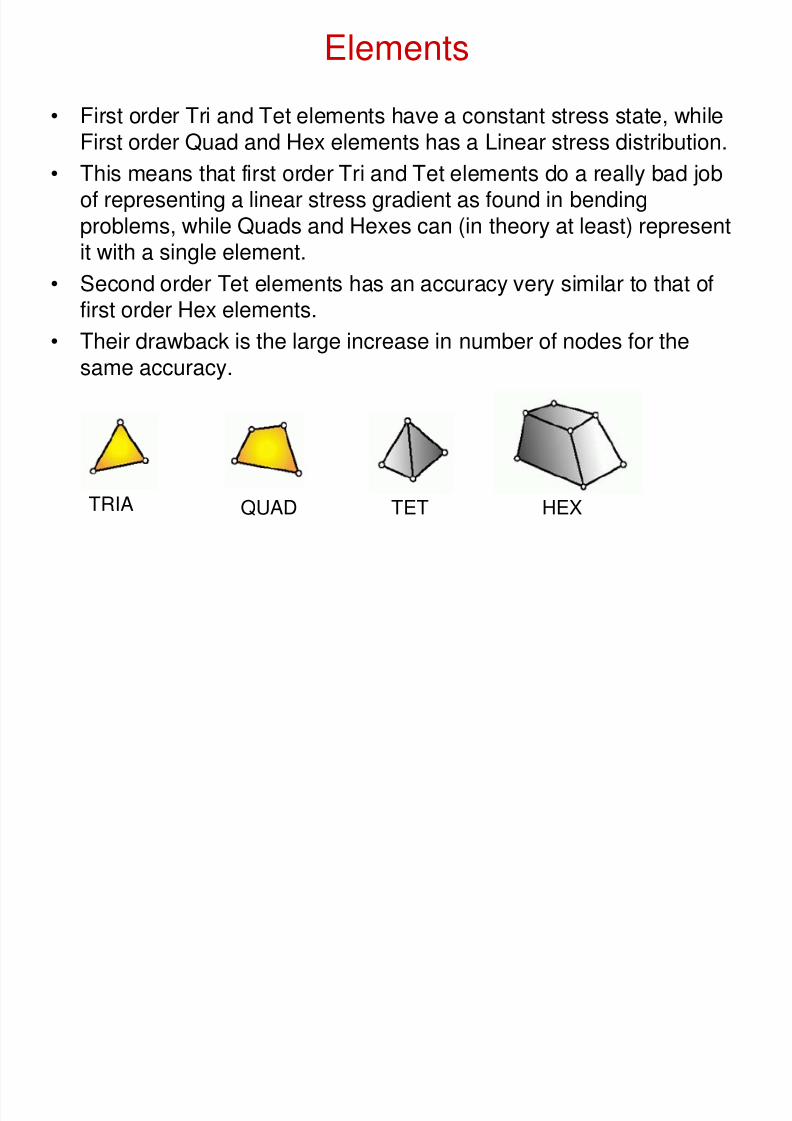
• First order Tri and Tet elements have a constant stress state, while
First order Quad and Hex elements has a Linear stress distribution.• This means that first order Tri and Tet elements do a really bad job
of representing a linear stress gradient as found in bendingproblems, while Quads and Hexes can (in theory at least) representit with a single element.
• Second order Tet elements has an accuracy very similar to that offirst order Hex elements.
• Their drawback is the large increase in number of nodes for thesame accuracy.
TRIA QUAD TET HEX

8/8/2019 Fea Simplified Theory
http://slidepdf.com/reader/full/fea-simplified-theory 20/44
Elements
• A factor that impacts element-choice for an analysis is how easy it is
to create a mesh using that type of element.
– Meshing of Curves into beam elements is trivial
– It is also easy to mesh surfaces to get Tri or Quad elements. Getting a
good mesh may take a bit longer when you need to specify where torefine a model.
– Meshing solid elements into Tet elements is simple. To generate a hex-mesh takes a lot longer because there is no consistent way to mesh
complex solids with good-quality Hex elements.
8/8/2019 Fea Simplified Theory
http://slidepdf.com/reader/full/fea-simplified-theory 21/44
Elements
• This brings us to the most important question in meshing:
– What element should I use?
• The answer is very simple:
– The simplest element that will answer the question that I have!
• Using too complex an element for the required job leads to a severepenalty in runtime and resource-usage

8/8/2019 Fea Simplified Theory
http://slidepdf.com/reader/full/fea-simplified-theory 22/44

8/8/2019 Fea Simplified Theory
http://slidepdf.com/reader/full/fea-simplified-theory 23/44
Elements
• Imagine modeling a Crane using solid elements.
– Of course it does not make sense. Beams do a much better job bybeing able to use a lot less elements to get the forces and moments.Catalogues exist that tells you what the force- and moment-handlingcapabilities of beams are, so in a lot of cases you may not even carewhat the stress is in the model!
• What happens to the connections between beams? – Can beam elements model this accurately?
– No, of course not. The beam mesh models a “perfect” load-transfer pathfrom one beam to the next, but no local stress-distribution are taken intoaccount.
– For this, a shell model may be more appropriate. The loads found by abeam model is applied to a shell-element sub-model to find the localstresses and stiffness of the connection.

8/8/2019 Fea Simplified Theory
http://slidepdf.com/reader/full/fea-simplified-theory 24/44
Elements
• Solid elements are used when there are significant through-
thickness stresses at some location. This happens at each locationwhere the thickness changes
• Take note:
– Even though a structure is made up of plates, it does not mean thatshell elements are the correct choice! If the ratio of the plate thickness
to the other dimensions of the plate is too small, the through-thicknessstress becomes very significant.
– A ratio of 1:10 is about the limit for any kind of accuracy for Thin-Shellelements and 1:5 for thick shells.
– More sensible would be 1:20 and 1:10.
– The difference between thin- and thick-shell elements is that thin shellsignores through-thickness shear stiffness, while thick-shells includethem.
– Recommendation: Always use thick shell elements as they will givemore accurate answers. They take slightly longer to run, which is theironly “drawback”

8/8/2019 Fea Simplified Theory
http://slidepdf.com/reader/full/fea-simplified-theory 25/44
Elements
Further recommendations:
• Use Quad elements rather than Tri elements
• Use first order elements unless it is Tri or Tet elements
• Use Hex elements if
– Computer resources are a problem (Not enough disk / Memory)
– The meshing-time will be less than the run-time (Nonlinear analysishaving to perform thousands of iterations)
• Use second order Tet (Tet10) elements for most cases where ananswer is needed quickly for linear analysis. They are about asaccurate a Hex-8 element but takes a lot less time to mesh acomplex structure. It’s also easy to check convergence: Simply re-mesh and re-run.

8/8/2019 Fea Simplified Theory
http://slidepdf.com/reader/full/fea-simplified-theory 26/44
Usefull Tips
• Aspect ratios
– Avoid elements with high aspect ratios• Caution when exceeding 3
• Alarm when exceeding 10
• Skewness and taper
– Skewness is the angle between two sides
• At least greater than 30°
– Taper is the ratio of the areas on two side of a diagonal
• Less than .5
• Physical Interfaces
– Elements must not cross interfaces

8/8/2019 Fea Simplified Theory
http://slidepdf.com/reader/full/fea-simplified-theory 27/44
Constraints
• Constraints are there to generate reaction forces that balances the
applied loads• In static analysis it is necessary to provide enough constraints to
prevent the model from behaving as a rigid body
– the minimum number of DOF that needs to be constrained (even for anunloaded model) is 6: The model may not be able to rotate or displacewithout reaction forces being generated.
– Even if there is no force in a global direction the model must beconstrained from moving in that direction
– Careful consideration of constraints to prevent spurious reaction forces
– Preferable to constrain translation dof’s rather than rotational dof’s
• Additional supports might be necessary to remove mechanisms
– Mechanisms occur most commonly in models using truss-, beams withreleased dof’s, and membrane elements
• Shells have no ‘drilling’ degrees of freedom
– need constraints in the out of plane rotation
– artificial stiffness in the drilling direction

8/8/2019 Fea Simplified Theory
http://slidepdf.com/reader/full/fea-simplified-theory 28/44
Constraints
• There are two types of constraints:
– An SPC (Single-point constraint) is a constraint that prescribes themotion of a single node
• Zero displacement/Prescribed displacement
• Specified in the global coordinate system
• Most programs make provision for rotating the coordinate system at the
node (skewing) – An MPC (Multi-point constraint) is a constraint equation that relate one
degree of freedom of a node to one or more degrees of freedom with alinear equation.
• This makes possible modelling a lever action between two nodes
• (Displacement 1 = 10* Displacement 2) or rigid connection between nodes(Displacement 1 = Displacement 2).
– A series of “rigid” elements are implemented in most FEA codes thatdefines the coefficients of the MPC constraint equations implicitly. Thismakes it a lot easier to use them.

8/8/2019 Fea Simplified Theory
http://slidepdf.com/reader/full/fea-simplified-theory 29/44
Constraints
• In Nastran, the “R” type elements are implemented through MPC
equations. – The RBE2 element is a Rigid connection, while
– the RBE3 is an averaging connection.
• SPC’s are easy to use and to understand the implications of
applying them.• “R” (Rigid) type elements are more difficult to use, but mostly stillstraightforward.
– Usually preferrable over MPC’s
• Easier to use
• Easier to display
• Less prone to error
• Explicit MPC’s can be very difficult to use, and it’s very easy to makea severe modelling mistake.

8/8/2019 Fea Simplified Theory
http://slidepdf.com/reader/full/fea-simplified-theory 30/44
Constraints
• In practice, SPC’s are used to represent the connection to the rest of
the universe. Think very carefully before applying a constraint: – Is the part of the structure you’re replacing with SPC’s really infinitely
stiffer then the part you are modeling? If not, at least the answers at theSPC’s will be wrong. Further away it may be correct assuming theconstraints are equivalent
– Does the structure want to deform in a way in real life that the constraint
does not allow? – Stress concentrations occur where parts of different stiffness are
connected together. Because an SPC is infinitely stiff, the stress-concentration effect is extreme. Therefore, except where the constraintsexactly model a physical phenomenon, the results at a constraint will bewrong.
• The same goes for MPC’s: Remember that they are infinitely rigid,thereby causing severe stress-concentrations. They can alsoseverely affect the load-path because of the severe stiffness.

8/8/2019 Fea Simplified Theory
http://slidepdf.com/reader/full/fea-simplified-theory 31/44
Constraints
• Symmetry is used where both the loads and the structure have
mirror symmetry. Anti-symmetry can also be used to advantage
• Advantages:
– Less computer resources are needed for a symmetry model than a fullmodel
– Boundary conditions are greatly simplified. The symmetry constraintsremoves certain rigid body modes without introducing any artificialstiffness
• Disadvantages:
– Symmetry is slightly more difficult to interpret than a full model
– Very difficult to present results to non-technical people (especially anti-symmetry!).

8/8/2019 Fea Simplified Theory
http://slidepdf.com/reader/full/fea-simplified-theory 32/44
Loads
• Loads applied can be point-, edge, face or body loads.
• To apply a load that is not impossible to re-create in real life, a Forceper unit area (pressure loading) or Force per unit volume (inertialloading) must be applied.
• In practical problems distributed loads are more common thanconcentrated loads
– Area (pressure loads)
• Wind load, water pressure, etc
– Body (Volume loads)
• Gravity, acceleration loads, etc

8/8/2019 Fea Simplified Theory
http://slidepdf.com/reader/full/fea-simplified-theory 33/44
Constraints: Best Practice in FEA
• Use minimum number of constraints where possible
• Loads are softer than constraints
• Large loads on few nodes -> singularity
• Must constrain 6 global dof’s
– Prevent rigid body motion
• All ‘components’ must have adequate constraints – Prevent mechanism
• Graphically check constraints
– Loads/BC’s – Plot Markers

8/8/2019 Fea Simplified Theory
http://slidepdf.com/reader/full/fea-simplified-theory 34/44
Analysis types
• Static analysis:
– A static analysis is useful to model a structure where the loading isapplied slow enough so that dynamic effects are not excited. If astructure is loaded at a frequency of about 1/3 of it’s first mode, a staticanalysis can be performed with good results.
• The model must be fully constrained (No rigid body modes)
• Mass is only needed if inertial (gravity) loading is applied• It’s the most common type of analysis performed. The key requirements of
a good static analysis are:
– A converged mesh (Relatively easy)
– Sensible constraints (Requires careful thought)
– Correct loading (Sometimes difficult to obtain)
– Good material properties (Usually easy)

8/8/2019 Fea Simplified Theory
http://slidepdf.com/reader/full/fea-simplified-theory 35/44
Analysis types
• Modal analysis: Used to find the un-damped modes of a structure
– There are no loads in a modal analysis, only boundary conditions. Forthe analysis to run, boundary conditions are not a requirement, butunless it is an aero-plane or a satellite, constraints needs to be used.
– The model must have mass and stiffness!
– Stresses can be requested. Yes they have meaning, but NOT to
determine if the structure will fail or not. The eigen-vectors (mode-shapes) reported by the FEM code are arbitrarily scaled. The stresscorresponds to this scaled deformation shape. Nothing more, nothingless. If you make a change to a model and the modal stress comesdown, it does NOT mean it is a better design!
– Eigenvalue is the square of the natural frequency
8/8/2019 Fea Simplified Theory
http://slidepdf.com/reader/full/fea-simplified-theory 36/44
Analysis types
• Buckling analysis: Used to find the scale factors for all the applied
loads for the structure to become unstable – Buckling loads for some structures are extremely sensitive to the initial
shape. No structure is perfect, so introduce small imperfections into themodel to determine how sensitive your model is to initial shape.
– One way to do this is to run a buckling analysis on the perfect shape,then to offset the mesh with the buckling shape within manufacturingtolerances, and then to re-run the analysis

8/8/2019 Fea Simplified Theory
http://slidepdf.com/reader/full/fea-simplified-theory 37/44
Analysis types
• Frequency response: This is a transfer-function between input loads
and every node in the model
• Time dependant (transient) analysis
– used to determine displacements, strains, stresses, and forces in astructure as they vary with time (Time history analysis)
– Similar to a static analysis, but with dynamics starting to play a role.
– Model should have mass, otherwise no dynamics will be present.
– No constraints are needed for the analysis to run because the inertia ofthe structure can balance the applied loads
– Input load can be
• Static (impulse)
• Harmonic
• or time dependant.

8/8/2019 Fea Simplified Theory
http://slidepdf.com/reader/full/fea-simplified-theory 38/44
8/8/2019 Fea Simplified Theory
http://slidepdf.com/reader/full/fea-simplified-theory 39/44
Linear Static Analysis
• All deformations and strains are small.
• Structural deformations are proportional to the loads applied.
• All materials behave in a linear elastic fashion.
• Loads are all static. (time independent)
• No boundary condition varies with time or application of load.(contact)

8/8/2019 Fea Simplified Theory
http://slidepdf.com/reader/full/fea-simplified-theory 40/44
Non-linear Analysis
• Causes of non-linear behaviour
– Material nonlinearity – Geometrical nonlinearity
• large strains (membrane analyses or metal forming)
• small strains, large displacements and/or rotations (cables, leaf-springs,
arches, fishing rods, snap-through buckling).
– Application of non-linear forces• Force following deflection (pressure loading)
• Stress stiffening (structures that are weak in bending e.g. pressurised
membranes, turbine blades rotating at a high speed)
– Nonlinear displacement boundary conditions
• Contact

8/8/2019 Fea Simplified Theory
http://slidepdf.com/reader/full/fea-simplified-theory 41/44
Non-linear Analysis
• Identifying nonlinear behaviour
– Stresses that exceed that of the limit of proportionality of the material. – Major changes in geometry
– Changes in geometry that remain after the process is finished.
– Processes involves buckling, crushing, wrinkling or plastic flows.
– Temperatures exceeding the melting temperature of the material.
– Large strains, finite strains can occur in hyper elastic materials.
– Nonlinear stress-strain laws, some materials have different compressivethan tensile strengths.
– Boundary conditions change due to the application of load (contact).
– The direction of load application changes with deformation (follower
forces such as pressures).

8/8/2019 Fea Simplified Theory
http://slidepdf.com/reader/full/fea-simplified-theory 42/44
Non-linear Analysis
• Tangent stiffness matrix
• Solution Techniques – Newton Raphson method
– Modified Newton Raphson
• Termination Control
– Displacement control
– Force Control
– Internal Energy
8/8/2019 Fea Simplified Theory
http://slidepdf.com/reader/full/fea-simplified-theory 43/44
Units
• FEA codes uses a set of consistent units. This means that basic
equations such as F=m*a should hold for the units chosen.• SI is a consistent set of units and it is strongly advised that it be
used.
• A seemingly attractive set of Engineering units is based on mm-N-s,which has pressures (stresses) in MPa, velocity in mm/s,
acceleration in mm/s^2 etc. – The catch is that mass is in Mg (tons) and density in Mg/mm^3!
– Units for thermal analysis are even more involved. It is very easy tomake a mistake during the process of calculating the correct units andthe required scale factors.
• Having consistent units for any dynamic-type of analysis isespecially important. Be very careful when not using SI!

8/8/2019 Fea Simplified Theory
http://slidepdf.com/reader/full/fea-simplified-theory 44/44
What’s coming
• Approaching a problem
• The importance of hand-calculations• Debugging a model
• Why open the Nastran deck?
• Help! I’m lost in the documentation…
• Dynamics basics• Nonlinear basics