Embed Size (px)
Citation preview

FE Simulation of FullFE Simulation of Full--Scale Dynamic Structure Scale Dynamic Structure Response including DamageResponse including Damage
Dr. Chris L. Mullen, P.E.Associate Professor of Civil Engineering
Composite Structures and Nano-engineering GroupDirector, Center for Community Earthquake Preparedness
Seminar on Blast SurvivabilityERDC Geotechnical and Structures Lab
Vicksburg, MS September 23, 2004

Blast/Seismic Sponsored ProjectsBlast/Seismic Sponsored Projects--ActiveActive
Disaster Resistant University (MEMA/FEMA, 2004, 2 yr)Disaster Resistant University (MEMA/FEMA, 2004, 2 yr)Estimated MultiEstimated Multi--Hazard Damage and Losses on Ole Miss Hazard Damage and Losses on Ole Miss CampusCampus
State Hazard Mitigation Plan for MS (MEMA, 2003, 1 yr)State Hazard Mitigation Plan for MS (MEMA, 2003, 1 yr)Estimated Damage and Losses for General Building Stock Estimated Damage and Losses for General Building Stock and Essential Facilities in Mississippiand Essential Facilities in Mississippi
Upcoming Seismic ConferenceUpcoming Seismic Conference
FEMA Regional Hazard CentersFEMA Regional Hazard CentersNational Earthquake ConferenceNational Earthquake ConferenceSt. Louis, MOSt. Louis, MO September 27September 27--30, 200430, 2004

Blast/Seismic Sponsored ProjectsBlast/Seismic Sponsored Projects
US90 West Pascagoula Bridge Demolition (MDOT, 2001)US90 West Pascagoula Bridge Demolition (MDOT, 2001)Simulated Response of Main Span Bents to Demolition BlastsSimulated Response of Main Span Bents to Demolition Blasts
I55/MS302I55/MS302--Goodman Road Bridge (MDOT, 2001, 2 yr)Goodman Road Bridge (MDOT, 2001, 2 yr)Critical Facility for MississippiCritical Facility for Mississippi--Emergency Escape RouteEmergency Escape Route
Ole Miss Oxford Campus (MEMA, 1999, 4 yr)Ole Miss Oxford Campus (MEMA, 1999, 4 yr)Selected Essential FacilitiesSelected Essential Facilities--Educational InstitutionEducational Institution
Baptist Memorial HospitalBaptist Memorial Hospital--DeSotoDeSoto (CUSEC, 1997, 1 yr)(CUSEC, 1997, 1 yr)Critical Facility for MemphisCritical Facility for Memphis--Emergency ResponseEmergency Response
SymposiumSymposium4 4 thth Int. Conf. Recent Adv. in Int. Conf. Recent Adv. in GeotechGeotech. EQE & Soil . EQE & Soil DynDyn..SoilSoil--Structure Interaction under Dynamic Loading, Structure Interaction under Dynamic Loading, for both Shallow and Deep Foundationsfor both Shallow and Deep Foundations

Universities: Ole Miss, Oxford Campus

EOC: Safe Room (Proposed), City Hall, Oxford

Fire Station: Station No. 1, City of Oxford
Oxford Fire Station No. 1 Emergency Response Facility

Schools: Oxford High School


Design Issues for a RC Office Building in Southaven, MSDesign Issues for a RC Office Building in Southaven, MS(Ph.D. Dissertation, I. M. K. (Ph.D. Dissertation, I. M. K. IsmailIsmail, 2000), 2000)

Standard Building Code (1994) Standard Building Code (1994) Analysis ProceduresAnalysis Procedures
If regular and H < 240 ft:Equivalent Lateral Force (Linear Static with Reduction for Inelastic Response)V = Cs W
If irregular or H > 240 ft:Modal Analysis (Linear Dynamic with Modal Reduction)x(t) = ∑ Xi zi(t) where (K- w2 M) Xi = 0
If approved by building official!:Time History(Nonlinear Dynamic, Only one that Satisfies Equilibrium)M a + C v + K d = P(t) where K=K(d)

Reinforcement Design Reinforcement Design U= (0.9+0.5 Av) D + L + E or U = (0.9U= (0.9+0.5 Av) D + L + E or U = (0.9--0.5 Av) D + E0.5 Av) D + E
ColumnType
Ultimate DesignAxial loadPu (Kips)
Ultimate DesignMoment (x-dir)
Mxu (ft-Kips)
Ultimate DesignMoment (y-dir)
Myu (ft-Kips)
ConcreteDimensions
(in)Reinforcement
A 120 56 47 12 X 12 4 # 10
B 240 63 43 12 X 20 6 # 7
C 225 65 59 12 X 16 4 # 10
D 465 74 44 12 X 24 4 # 7
Col. A12 "
12 "4 #10
Tie #3@12
Col. C12 "
16 " 4 #10
Tie #3@12
Col. B
12 "
20 "
6 #7Tie
3@12"
Col. D12 "
6 #7
Tie3@12"

Story Drifts and StabilityStory Drifts and Stability
∆
V P
θ < 0.10Neglect P- Delta
(∆/ h) < 0.10Story Drift OK
h
StoryLevel
Height hx (ft)
Gravity Load Pi =∑ Wx (k)
LongitudinalStory Drift
∆i (in)
Transverse Story Drift
∆i (in)
Story ShearVi (k)
Transverseθ =Pi ∆i / Vi hi
Longitudinalθ =Pi ∆i / Vi hi
1st Story 12 1140 0.17 0.27 91.2 0.025 0.016
2nd Story 24 760 0.13 0.20 76.0 0.014 0.008
3rd Story 36 380 0.06 0.08 45.6 0.005 0.004
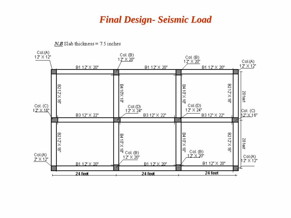
Final DesignFinal Design-- Seismic LoadSeismic Load

Fundamental Free Vibration Modes of the Building Fundamental Free Vibration Modes of the Building 3D ABAQUS3D ABAQUS-- No SoilNo Soil--Structure Interaction (SSI)Structure Interaction (SSI)
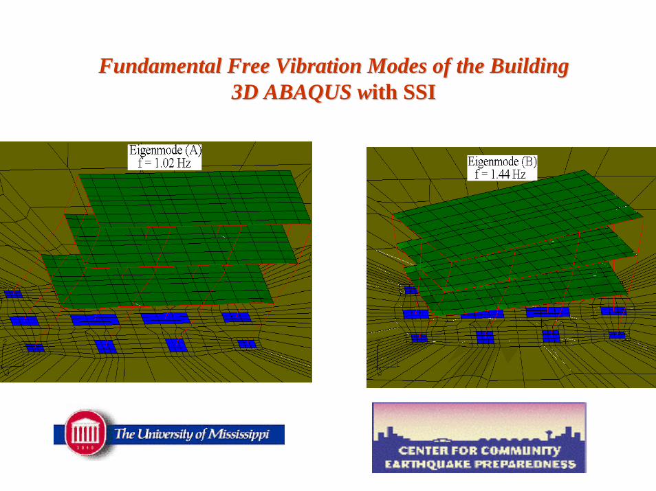
Fundamental Free Vibration Modes of the Building Fundamental Free Vibration Modes of the Building 3D ABAQUS w3D ABAQUS with SSIith SSI

Generation of Synthetic Earthquake MotionsGeneration of Synthetic Earthquake Motions
Layer-1
Layer-2
Layer-3 Soil
Prof
ile(P
roS
hake
Inpu
t)
New MadridFault
Bedrock Acceleration Used inthe Soil Models
(SMSIM output)(ProShake Input)
Ground Surface AccelerationUsed in the Fixed-base and
Linear Springs Models
(ProShake Output)
R=100km, M=7.5(SMSIM Input)
Bedrock
Wav
e Pr
opag
atio
n
3-story Building
Ground Surface

Southaven Soil ProfileSouthaven Soil Profile-- ProShakeProShake Site Response AnalysisSite Response AnalysisLayer
1
2
3
4
5
Description
Firm to stiff brown clayey silt( H = 16.5 ft )
Firm to stiff brown clayey silt( H = 21.5 ft )
Dense red and orange clayeymedium sand and gravel
( H = 10 ft )
Medium dense to dense pink orange and tan fine sand
( H = 60 ft )
Seismic Bedrock, Vs > 2000 ft/s( H = Semi-infinite )
Shear Wave Velocity( ft / s )
Unit Weight( lbf / ft3 )
555
985
1230
1940
116
118
106

ProShakeProShake Soil Material Degradation Curves for SouthavenSoil Material Degradation Curves for Southaven
0
0.2
0.4
0.6
0.8
1
0.0001 0.001 0.01 0.1 1 10
Shear Strain
Shea
r M
odul
us R
atio
(G/G
o)
Layers 1,2Layer 3
Layer 4Layer 5
0
10
20
30
0.0001 0.001 0.01 0.1 1 10
Shear Strain
Dam
ping
Rat
io (%
) Layers 1,2
Layers 3,4
Layer 5

SMSIM/SMSIM/ProShakeProShakeSynthetic Ground Motions for SouthavenSynthetic Ground Motions for Southaven
-0.3
-0.2
-0.1
0
0.1
0.2
0.3
0 5 10 15 20 25
Acc
eler
atio
n (g
)
Layer 2
Layer 5
-0.1
-0.05
0
0.05
0.1
0 5 10 15
Acc
eler
atio
n (g
)
Layer 2
Layer 5
M=6
M=7

SMSIM / SMSIM / ProSHAKEProSHAKE/ 3D SAP2000 Simulation/ 3D SAP2000 SimulationLinear Roof Response (No SSI, M=7) Linear Roof Response (No SSI, M=7)
-0.5
-0.4
-0.3
-0.2
-0.1
0
0.1
0.2
0.3
0.4
0.5
0 5 10 15 20 25
Time(sec)
Acc
eler
atio
n (g
)
Response of structure
Response of soil
Input of soil

3D ABAQUS Simulation, M=7.53D ABAQUS Simulation, M=7.5
-0.75
-0.5
-0.25
0
0.25
0.5
0.75
0 5 10 15 20
Acc
eler
atio
n (g
)Fixed-Base
Linear-Springs
Linear-Soil
-0.75
-0.5
-0.25
0
0.25
0.5
0.75
0 5 10 15 20
Time (s)
Acc
eler
atio
n (g
)
Linear-Soil
Non-Linear Soil
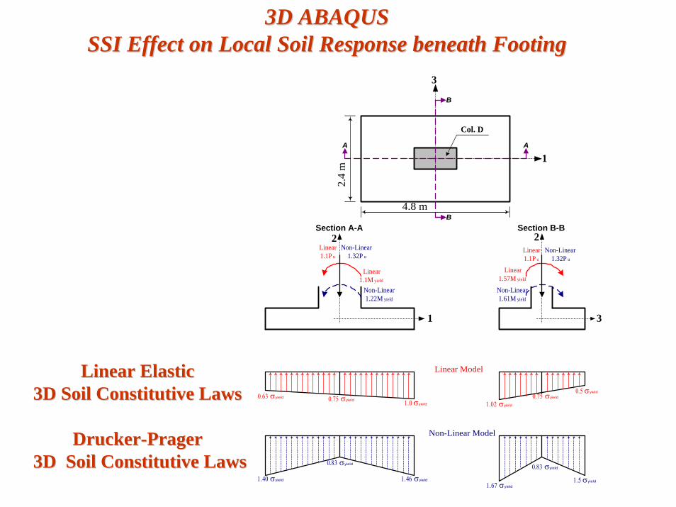
3D ABAQUS 3D ABAQUS SSI Effect on Local Soil Response beneath FootingSSI Effect on Local Soil Response beneath Footing
1
3
AA
B
B
2.4
m
4.8 m
Col. D
Section A-A Section B-B
Linear1.1M yield
Non-Linear1.22M yield
1
2
Linear1.57M yield
Non-Linear1.61M yield
3
2
Linear Model
Non-Linear Model
Linear1.1P u
Non-Linear1.32P u
Linear1.1P u
Non-Linear1.32P u
1.02 σyield
0.5 σyield0.75 σyield0.75 σyield 1.0 σyield
0.63 σyield
1.5 σyield1.67 σyield
0.83 σyield
1.46 σyield
0.83 σyield
1.40 σyield
DruckerDrucker--Prager Prager 3D3D Soil Constitutive LawsSoil Constitutive Laws
Linear Elastic Linear Elastic 3D Soil Constitutive Laws3D Soil Constitutive Laws

Seismic Vulnerability AnalysisSeismic Vulnerability AnalysisBaptist Memorial HospitalBaptist Memorial Hospital--DeSotoDeSoto

3D ABAQUS Simulation3D ABAQUS SimulationEffects of SSI and Pounding of Adjacent BuildingsEffects of SSI and Pounding of Adjacent Buildings

AnimationAnimation

RC Towers w/ RC Towers w/ PrestressedPrestressed Floor Slabs Floor Slabs Vulnerability of Roof Utility StructureVulnerability of Roof Utility Structure

AnimationAnimation
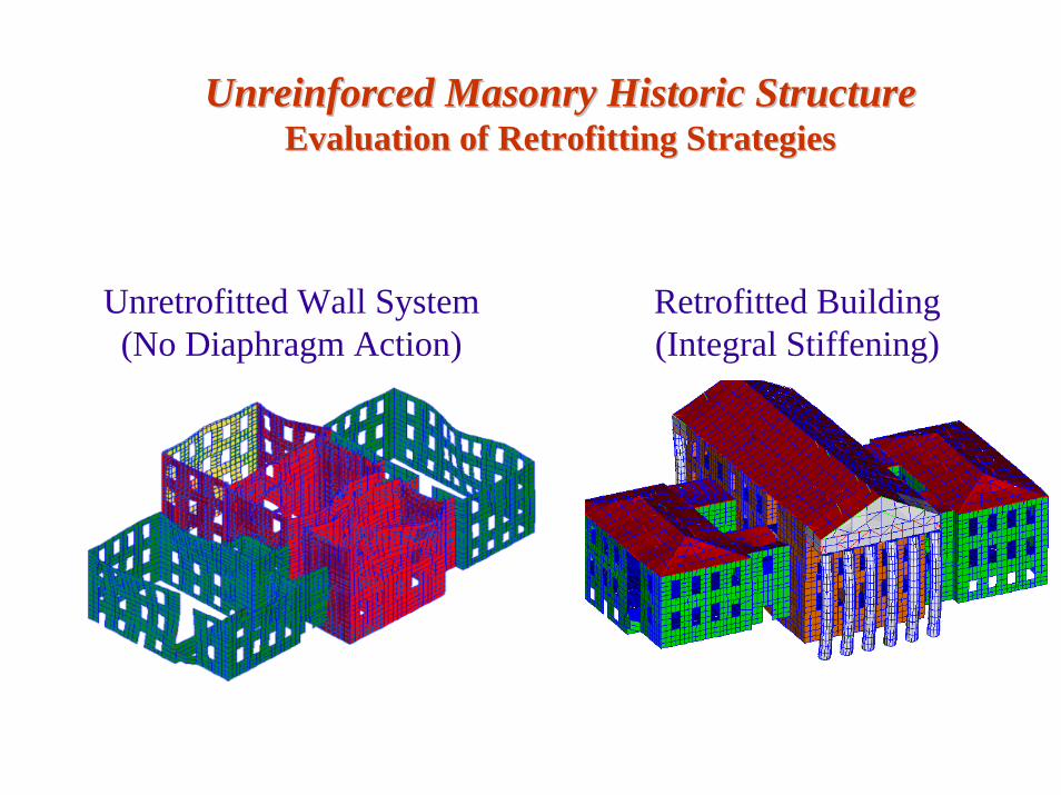
UnreinforcedUnreinforced Masonry Historic StructureMasonry Historic StructureEvaluation of Retrofitting StrategiesEvaluation of Retrofitting Strategies
Unretrofitted Wall System(No Diaphragm Action)
Retrofitted Building(Integral Stiffening)

RC Stadium with Steel Space Frame DomeRC Stadium with Steel Space Frame DomeDome/Seating Connection VulnerabilityDome/Seating Connection Vulnerability

RC Student Commons w/RC Student Commons w/PrestressedPrestressed SlabsSlabsVulnerability from Tall Glass WallsVulnerability from Tall Glass Walls
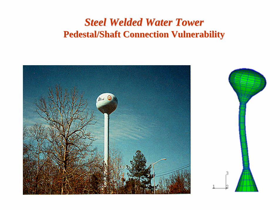
Steel Welded Water TowerSteel Welded Water TowerPedestal/Shaft Connection VulnerabilityPedestal/Shaft Connection Vulnerability

Deteriorating Highway BridgeDeteriorating Highway BridgeRC Column VulnerabilityRC Column Vulnerability

M=8 3D ABAQUS SimulationM=8 3D ABAQUS SimulationBenefit of Retrofitting (e.g. Column Wraps)Benefit of Retrofitting (e.g. Column Wraps)
Bottom of NE Corner Column
-1
-0.5
0
0.5
1
-1 -0.5 0 0.5 1
K / KY
M /
MY
Bottom of NE Corner Column
-1
-0.5
0
0.5
1
-1 -0.5 0 0.5 1
K / KY
Retrofitted BridgeExisting Bridge

II--55 Interstate Highway Bridge 55 Interstate Highway Bridge Substructure Vulnerability StudySubstructure Vulnerability Study
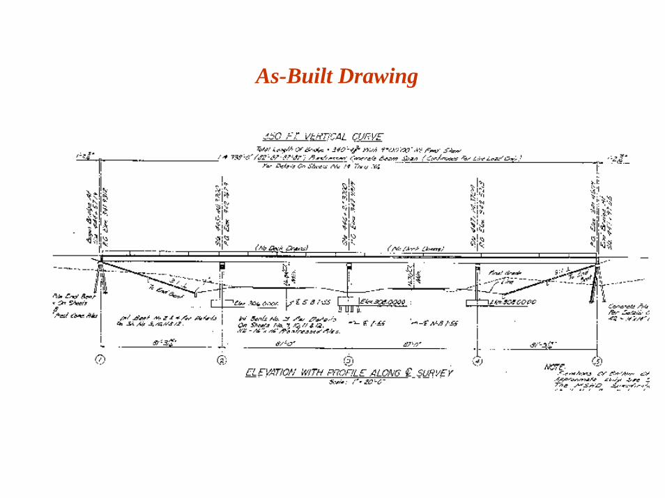
As-Built Drawing

Bridge Site ConditionsBridge Site ConditionsTop of DeckTop of Deck
North Bridge (Phase II)
West Bound Traffic
South Bridge (Phase I)
East Bound Traffic
1 inch gap between the two bridges

Bridge Site ConditionsBridge Site ConditionsIntermediate Bent SubstructuresIntermediate Bent Substructures

Level 1 (Pushover) Analysis Level 1 (Pushover) Analysis InIn--Plane Flexure/Shear CapacityPlane Flexure/Shear Capacity
Nonlinear (Typ.)
Restrain 6-DOF (Typ.)
Rigid (Typ.)
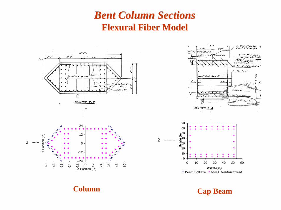
Bent Column SectionsBent Column SectionsFlexural Fiber ModelFlexural Fiber Model
Column
1 1
-24
-12
0
12
24
-60
-48
-36
-24
-12 0 12 24 36 48 60
X Position (In)
Y P
ositi
on (I
n)
22
Cap Beam

Nonlinear Fiber 1D Constitutive LawsNonlinear Fiber 1D Constitutive Laws
0
1
2
3
4
5
6
0.000 0.005 0.010 0.015 0.020
Strain
Stre
ss (k
si)
Unconfined ConcreteConfinedTensile
0
20
40
60
80
100
0 0.05 0.1 0.15
Strain
Stre
ss, k
si
Concrete Fibers
Steel Fibers

Nonlinear Static Response SimulationNonlinear Static Response Simulation
0
0.5
1
0 0.01 0.02 0.03 0.04 0.05Drift (d/L)
Loa
d (P
/Pu)
ABAQUS1st Crack1st YieldCollapse

Level 2 (Multimode Spectral) AnalysisLevel 2 (Multimode Spectral) AnalysisFixed Base Structure ModelFixed Base Structure Model
Accelerometer positions for ambient vibration measurementsX- Input at roadway level
Y- Output at bent cap level
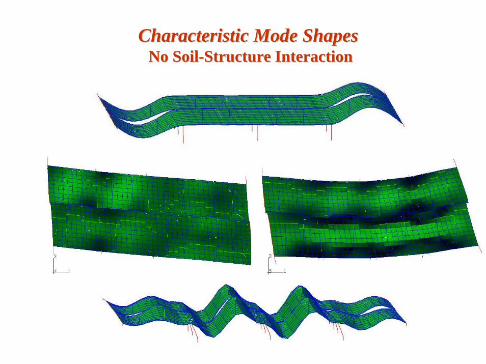
Characteristic Mode Shapes Characteristic Mode Shapes No SoilNo Soil--Structure InteractionStructure Interaction

Field Vibration MeasurementField Vibration Measurement

Sample Virtual Network Analyzer Record Sample Virtual Network Analyzer Record

FEM versus Vibration Based IdentificationFEM versus Vibration Based Identification
Fixed Base Model(2.96 Hz.)
SSI Model(3.01 Hz.)
VNA Extraction(2.99 Hz.)

Level 3 (Time History) ModelLevel 3 (Time History) ModelWith SoilWith Soil--Structure InteractionStructure Interaction
MS 302Goodman Road
I-55 to Memphis

Substructures: Columns, Footings, Piles and AbutmentsSubstructures: Columns, Footings, Piles and Abutments

-1
0
1
-1 0 1
K/Ky
M/M
y
-2
-1
0
1
2
-2 -1 0 1 2
K/Ky
M/M
y
-3
-2
-1
0
1
2
3
-3 -2 -1 0 1 2 3
K/Ky
M/M
y
(M=8)(M=6) (M=7)
3D 3D HysteresisHysteresisPerformancePerformance--Based EvaluationBased Evaluation
1-Axis (M = 8)
-2
-1
0
1
2
-3 -2 -1 0 1 2 3
K/Ky
M/M
y
ColumnColumn
Abutment PileAbutment Pile1-Axis (M = 7)
-2
-1
0
1
2
-2 -1 0 1 2
K/Ky
M/M
y
1-Axis (M = 6)
-1
-0.5
0
0.5
1
-1 -0.5 0 0.5 1
K/Ky
M/M
y

US90 Highway BridgeUS90 Highway BridgeDemolition Blast StudyDemolition Blast Study

Substructures: Columns, Piles, Soil SpringsSubstructures: Columns, Piles, Soil Springs
BearingsBearings

Blast Pulse, Pile Deformation, and Bending MomentBlast Pulse, Pile Deformation, and Bending Moment
-4000
-2000
0
2000
4000
6000
8000
10000
12000
0 0.001 0.002 0.003 0.004 0.005 0.006 0.007 0.008 0.009
Time, t (s)
Lin
e L
oad,
w (k
/ft)

Thanks for Your Attention !Thanks for Your Attention !