Embed Size (px)
Citation preview
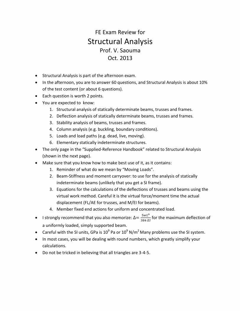
FE Exam Review for
Structural Analysis Prof. V. Saouma
Oct. 2013
Structural Analysis is part of the afternoon exam.
In the afternoon, you are to answer 60 questions, and Structural Analysis is about 10%
of the test content (or about 6 questions).
Each question is worth 2 points.
You are expected to know:
1. Structural analysis of statically determinate beams, trusses and frames.
2. Deflection analysis of statically determinate beams, trusses and frames.
3. Stability analysis of beams, trusses and frames.
4. Column analysis (e.g. buckling, boundary conditions).
5. Loads and load paths (e.g. dead, live, moving).
6. Elementary statically indeterminate structures.
The only page in the “Supplied-Reference Handbook” related to Structural Analysis
(shown in the next page).
Make sure that you know how to make best use of it, as it contains:
1. Reminder of what do we mean by “Moving Loads”.
2. Beam-Stiffness and moment carryover: to use for the analysis of statically
indeterminate beams (unlikely that you get a SI frame).
3. Equations for the calculations of the deflections of trusses and beams using the
virtual work method. Careful it is the virtual force/moment time the actual
displacement (FL/AE for trusses, and M/EI for beams).
4. Member fixed end actions for uniform and concentrated load.
I strongly recommend that you also memorize:
for the maximum deflection of
a uniformly loaded, simply supported beam.
Careful with the SI units, GPa is 109 Pa or 109 N/m2 Many problems use the SI system.
In most cases, you will be dealing with round numbers, which greatly simplify your
calculations.
Do not be tricked in believing that all triangles are 3-4-5.
26 (ivil Disdpline回SpecificReview for the FE/EIT Ex目m
From the PVC, the low point is located at
m
A吐
Aせ十m
一
m
的町一つG
A斗A
FL
一A吐
00
一Aせ
一一一一
m
Aせ
4パヨ+
L一2
Determine the tangent offsetぅ仏 atthe low point.
y=iG2 -G1)X2
2L -(0.016一(-0.02))(444 m)2
(2)(800 m)
ニ 4.44m
eleVlow point = 742.12 m十4.44m
= 746.56 m (747 m)
The answer is B.
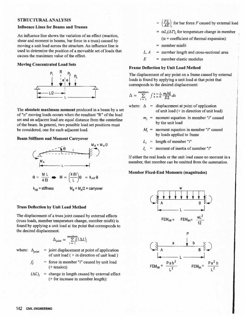
STRUCTURAL ANA町SIS
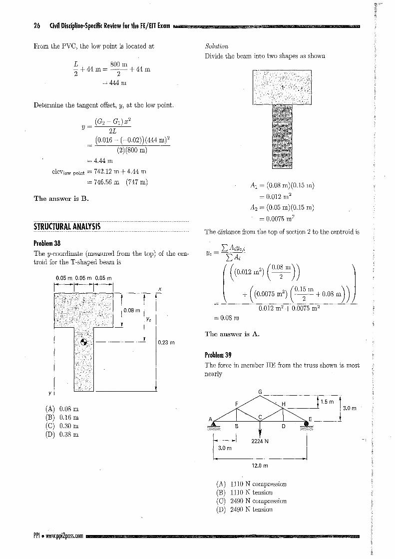
Problem 38
The y-coordinate (mea師su町1tむroぱidfor the T -shaped beam is
「一「ーr---I
J08m比
X
y
0.23 m
(A) 0.08 m (B) 0.16 m (C) 0却 m
(D) 0.38 m
PPI・附W押i2pllss.com
Solution
Divide七hebeam in七otwo shapes as shown
Al = (0.08 m)(0.15 m)
= 0.012 m2
A2 = (0.05 m)(0.15 m)
ェ 0.0075m2
The dis七ancefrom七hetop of section 2 to the centroid is
Uc=Z生Yc,i2乞:Aん4
( (川十((0.0075 m
2) (平十0叫))
ニ 0.08m
The answer is A.
Problem 39
The force in member HE from the七russshown is mos七nearly
G
~1
12.0 m
(A) 1110 N compression (B) 1110 N tension (C) 2490 N compression (D) 2490 N七ension
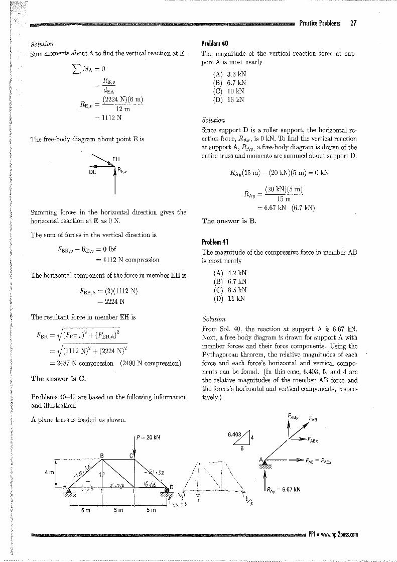
Solution
8um moments about A to find the vertical reaction at E.
:Z=MA = 0
RE,匂
dEA
RH:" = i2224 N)(伊6m) U円'げν1ロ2m
=1112N
The free-body diagram abou七pointE is
、....._.EH
DE !RE,ν
8umming forces in the horizontal direction gives the
horizontal reaction at E as 0 N.
The sum of forces in位1evertical direction is
FEH,υ-RE,り=0 lbf
= 1112 N compression
The horizontal component of the force in member EH is
FEH,h = (2)(1112 N)
= 2224 N
The resultan七forcein member EH is
FEH=V(Fi凹,出(Fi叫2
=ゾ(1112N)2十(山 N)2
ニ 2487N compre回 on (2490 N∞mpr出品on)
The answer is C.
Problems 40-42 are based on the following information
and illustra七ion.
A plane truss is loaded as shown.
Pr目di(eProblems 27
Problem 40
The magnitude of the vertical reaction force at sup-
port A is most nearly
(A) 3.3 kN
(B) 6.7 kN
(0) 10 kN
(D) 16 kN
Solution
8ince support D is a roller supportう thehorizontal re-
ac七ionforceうRAx,is 0 kN. To find the vertical reaction
at support A, RAy, a free-body diagram is drawn of the
entire七russand moments are summed about suppor七D.
RAy(15 m) -(20 kN)(5 m) = 0 kN
RA" = i20 kN)(5 m) 吋 15m
= 6.67 kN (6.7 kN)
The answer is B.
Problem 41
The magnitude of the compressive force in member AB is most nearly
(A) 4.2 kN
(B) 6.7凶
(0) 8.5 kN
(D) 11 kN
Solution
From 801. 40, the reaction at support A is 6.67 kN.
Nextぅafree同 bodydiagr乱mis drawn for support A with member forc田 and七heirforce components. Using七he
Pythagorean theorem, the relative magnitudes of each force and each forceうshorizontal and vertical compo-
m臨 canbe found. (In this case, 6.403, 5, and 4 are
the relative magni七udesof the member AB force and the forcesうshorizontal and verむicalcomponen七s,respec-tively.)
FAEx
PPI.附 w.ppi2p日sS.com
28 Civil Discipline-Specifi( Review for fhe FE/EIT Ex目m
For equilibrium, all forces on a free body mus七sumto
o kN. Summation of vertical forces giv<回
FABy + RAy = 0 kN
This can be rearranged to give
FABy = -RAy = -6.67 kN
Recall that joints in七russesare frictionless, so no bend-ing moments exist.
The force and its components are proportional to the
geometric lengもhsof the triangle sides.
一 (6.403m ¥一.l'AB = I一一了一一一一 I.l'AB'U
¥ 4 m I ν
(6.403 m ¥ =(τ'~--- ) (-6.67 kN)
= -10.68 kN (-11 kN)
The answer is negative. This means that the calculated
force is in the opposi七edirec七ionto七heassumed force di-
rection on the free-body diagram. 8ince the member AB
force w回 assumedto apply tension on the free伊 bodydi-
agram, the negative answer means that member AB is
m compreSSlOn.
The answer is D.
Problem 42
The magnitude of the force in member EF is mos七ne乱rly
(A) 4.2 kN
(B) 5.3 kN (C) 6.7 kN
(D) 8.3悶
Solution
From 801. 41, FABy is -6.67 日~. The horizontal com-
ponent of the member AB force is
MH
L且
可
tnhv
U
F
O
E
U
ρ
h
u
凡
ト
N
¥1111/¥
、111I/Lι
m一m
m一mお
vhu
一A住民
U
一an笹
口
δ
/ell-¥/1111¥
一
一一一一一一
Z
B
A
F
For equilibrium at support A, the sum of the horizontal forces must be equal to 0 kN. The force in member AE is
FAE = FAEx
= -FABx
= -(-8.33 kN)
= 8.33 kN
PPI.附 W押i2p日ss.com
The posi七ivesign in the calculated member AE force
means that the assumed direction of the force on七he
free-body diagramう whichindicates tension, is in the
same direction as the calculated force.
A free-body diagram of joint E will show that the ver-
tical member BE is unable to sustain any horizontal
force. Therefore, the force in member ~F is the same as the force in member AE.
FEF =FAE
= 8.33 kN (8.3 kN)
The answer is D.
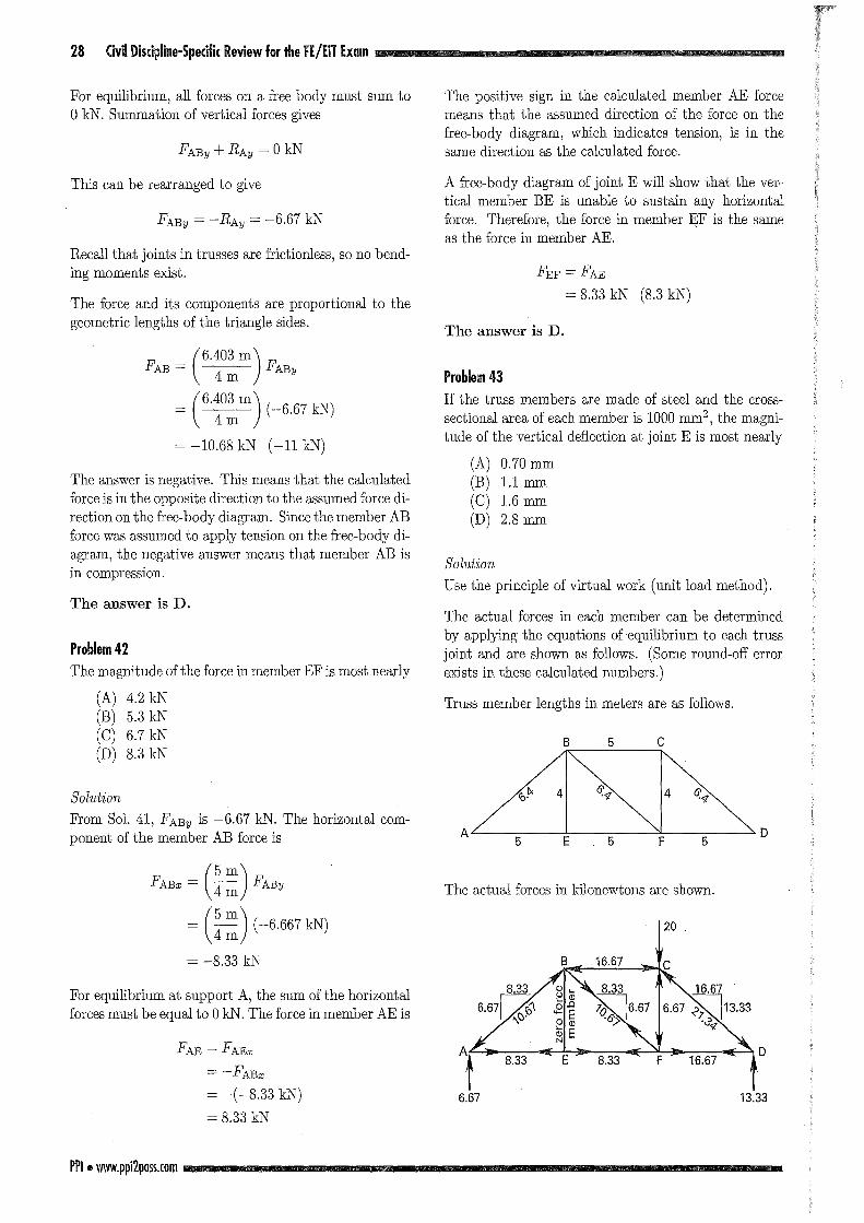
Problem 43
If the truss members are made of steel and the cross-
sectional area of each member is 1000 mm2, the magni-tude of the vertical defl.ection抗 jointE is most nearly
(A) 0.70 mm
(B) 1.1 mm
(C) 1.6 mm
(D) 2.8 mm
Solution
Use the principle of vi巾 alwork (unit load method).
The actual forces in each member can be determined
by applying the equations of equilibrium to each truss
joint and are shown回 follows.(80me round-off error
exists in these calculated numbers.)
τ'russ member lengths in meters are as follows.
B5 C
AT< 41 ず々'" 14 仏
/ I 、 士一 '::"'D5 E 5 F
The actual forces in kilonewtons are shown.
20
D
6.67 13.33
Pradice Problems 29
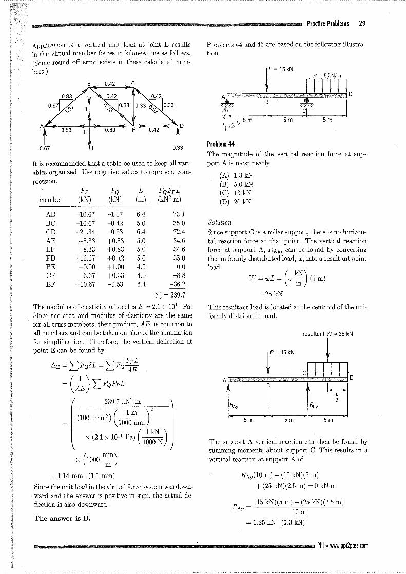
Problems 44 and 45 are based on the following illustra司
tion.
Application of a vertical unit load at joi凶 Eresults
in the virtual member forces in kilonewtons as follows.
(Some round off eロorexis匂 inthese calculated num-
bers. )
町5m ↑ 5m 手5m J D
Problem 44
The magnitude of the ver七icalreac七ionforce at sup-
port. A is most nearly
0.33
It is recommended that a table be used to keep all vari-
ables organized. Use negative values to represent com-
presslOn.
0.67
1.3kN
5.0 kN
13 kN
20 kN
(A) (B) (C) (D)
FQFpL
(kN2岨)L
(m) FQ
(kN) Fp
(kN)
Solution
Since suppor七Cis a roller suppor七ぅ thereis no horizon-
tal reaction force at that point. The vertical reaction
force at support Aう RA約 canbe found by converting
the uniformly distributed load,ω, into a resultant point
load.
m
vhu
¥、、EB』t/ノ
凶一
m
vhu
/III-
、¥二
到
L
i
ω
引制
一一一一
W
member
73.1
35.0
72.4
34.6
34.6
35.0
0.0
8.8
-36.2
I: = 239.7
6.4 5.0
6.4 5.0
5.0
5.0
4.0
4.0
6.4
-1.07 -0.42
0.53
+0.83
+0.83
十0.42+1.0。+0.33
-0.53
10.67
-16.67
-21.34 十8.33
十8.33
+16.67
十0.00
-6.67
+10.67
BCDEFDEFF
ABCAEFBCB
This resul七antload is located a七thecentroid of the uni-
formly distributed load.
The modulus of elasticity of steel is E = 2.1 X 10¹¹ Pa.
Since the area and modulus of elasticity are the same
for all truss members,七heirproduct, AEうiscommon to
all members and can be taken outside of the summation
for simpli五cation.Thereforβ, the vertical deflection at point E can be found by
r山一
EH一A
?
Q
L
EA
い
P
εv
bz
M¥l/
R
l一E
Z仁い
E
A
5m
The support A vertical reaction can then be found by
summing moments about support C. This results in a
vertical reaction at support A of
5m (1000 mm2) (吋:m)
×川1Pa) (品)
RAy(10 m) -(15 kN)(5 m)
+(25 kN)(2.5 m) = 0 kN-m
x (1000誓)(1.1 mr吋
ISince the unit load in the virtual force system was down-
. ward and the answer is positive in sign, the actual de-
丑ectionis also downward. RA"ニ (15kN)(5 m) -(25 kN)(2.5 m)
吋 10m
(1.3 kN) The answer is B.
PPI.附 W押i2p日sS.com
= 1.25 kN
ェ1.14rnrn
30 Civil Discipline-Specific Review for the FE/EIT Exam
Since the answer is positive in sign, the direc七ionof the
calculated reaction is the same as that of the assumed
reactioni that is, the direction of the reaction is upw乱rd.
The answer is A.
Problem 45
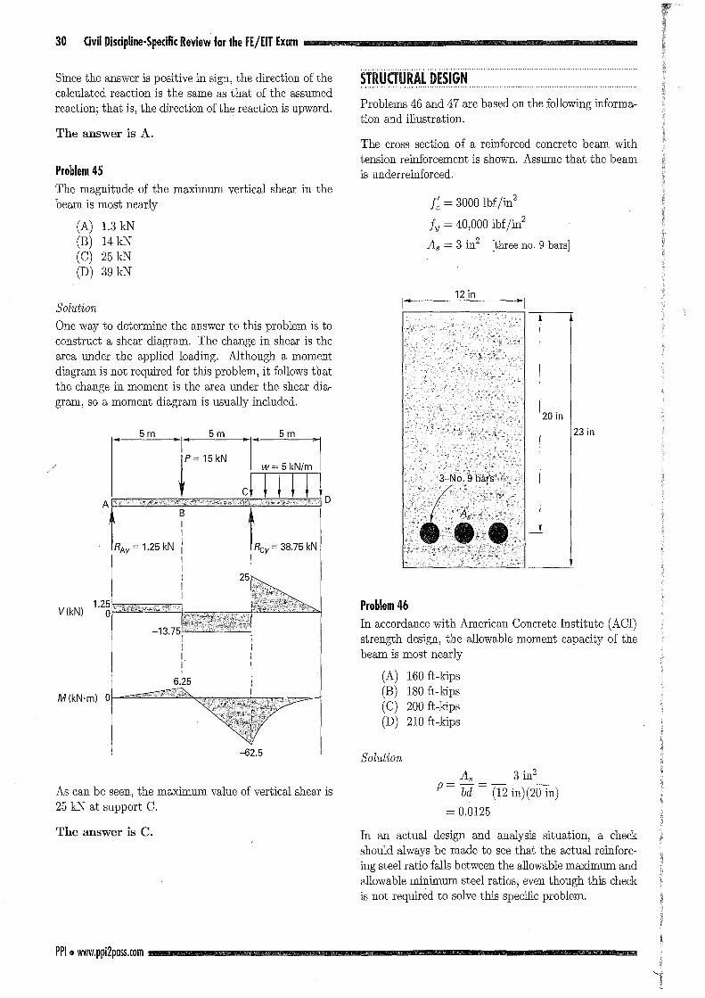
The magnitude of the maximum vertical shear in the
beam is most nearly
(A) 1.3 kN (B) 14 kN (C) 25 kN (D) 39 kN
Solution
One way七odetermine the answer to this problem is to
construct a shear diagram. The change in shear is the
area under the applied loading. Although a momen土
diagram is not required for this problemう itfollows that
the change in momen七isthe area under the shear dia-
gram, so a moment diagram is usually included.
/ llF15kN LkN/m I 1c~ ~ ~ ~ ~ ~
V(kN)
M(kN'm) 0
-62.5
As can be seen, the maximum value of vertical shear is 25 kN at support C.
The answer is C.
PPI ・附W押i2p日sS.com
STRUCTURAL DESIGN
Problems 46 and 47 are based on the following informa-tion and illustration.
The cross section of a reinforced concrete beam with
tension reinforcement is shown. Assume that the beam
is underreinforced.
五=3000 lbfjin2
ん=40,000 lbfjin2
As = 3 in2 [three no. 9 bars]
20in
23in
Problem 46
In accordance with American Concrete Institute (ACI)
凶rengthdesign, the allowable moment capaciもyof七he
beam is most nearly
(A) 160 ft-kips
(B) 180 ιkips
(C) 200 ft-kips
(D) 210 ft-kips
Solution
一n
2i一如
-{
3一m
一qG
一1i
ニ
おーー
ん一
Mω
一一一一
ρ'
In an actual design and analysis situation,乱 check
should always' be made to see th乱,tthe actual reinforc-
ing steel ratio falls between the allowable maximum and
allowable minimum steel ratios, even though this check is not required to solve this specific problem.
46 Civil Discipline-Specific Review for the FE/EIT Exam
The minimum required length of spiral transition be-
tween the curve and road is most nearly
(A) 28 ft (B) 36此
(0) 44氏
(D) 72 ft
36. The design requirements for a section of highway
with a 1.5% grade are as follows.
design speed = 80 kmjh coefficient of friction = 0.35 driver reaction time = 2.0 s
driver eye height = 1.2 m
object (to be師 oided)height = 0.2 m
The downhi1l design braking distance for this highway is most nearly
(A) 45 m
(B) 75 m
(0) 100 m
(D) 120 m
37. A crest on a section of highway consists of a vertical
curve with a 1500 m radius and a posi七ive1 % grade fol-
lowed by a negative 3% grade. The design requirements
are as follows.
design speed = 80 kmjh driver eye height = 1.2 m
object (to be avoided) height = 0.2 m
日七oppingsight distanceデ300m
The minimum required length of vertical curve needed
to sa七isfythe design stopping sight dis七anceis most
nearly
(A) 680 m
(B) 700 m
(0) 760 m
(D) 840 m
38. A superpave design mixture for a highway with
ESALs < 107 h回 anominal maximum aggregate size
of 19 mm. The mixture has been tested and has the
following characteristics:
air voids = 4.0%
VMAニ 13.2%
VFA = 70% dust-to-asphalt ratio = 0.97
at N = 8 gyrationsうGmmニ 87.1%
at N = 174 gyrationsぅGmm= 97.5%
PPI・附w.ppi2pass.com
Do these characteristics satisfy七heircorresponding su-
perpave requirements?
(A) Yes, all the p釘 ametersare within組 acc叩七回
able range.
(B) No, the VMA is excessive
(0) No, the dust-to田 asphaltratio is too high
(D) No, Gm m at Nm日 istoo high.
39. A road leading to a s七onequarry is traveled by
40 trucks, wi七heach truck making an average of 10 trips
per day. When fully loaded, each truck consis七sof a
front single axle transmitting a force of 10,000 lbf and two rear tandem axlesう eachaxle transmitting a force
of 20,000 lbf. The load equivalency factor for the front
single axle is 0.0877. The load equivalency f配 torfor
each rear tandem axle is 0.1206.
The 18,000 lbf equivalent single axle load (ESAL) for the truck tra伍con this road for 5 yr is most nearly
(A) 0.33 ESAL
(B) 130 ESAL
(0) 48,000 ESAL (D) 240,000 ESAL
Problems 40 and 41町 ebased on the following i1lus七ra-tion.
↓ド15kNi「↓51NK
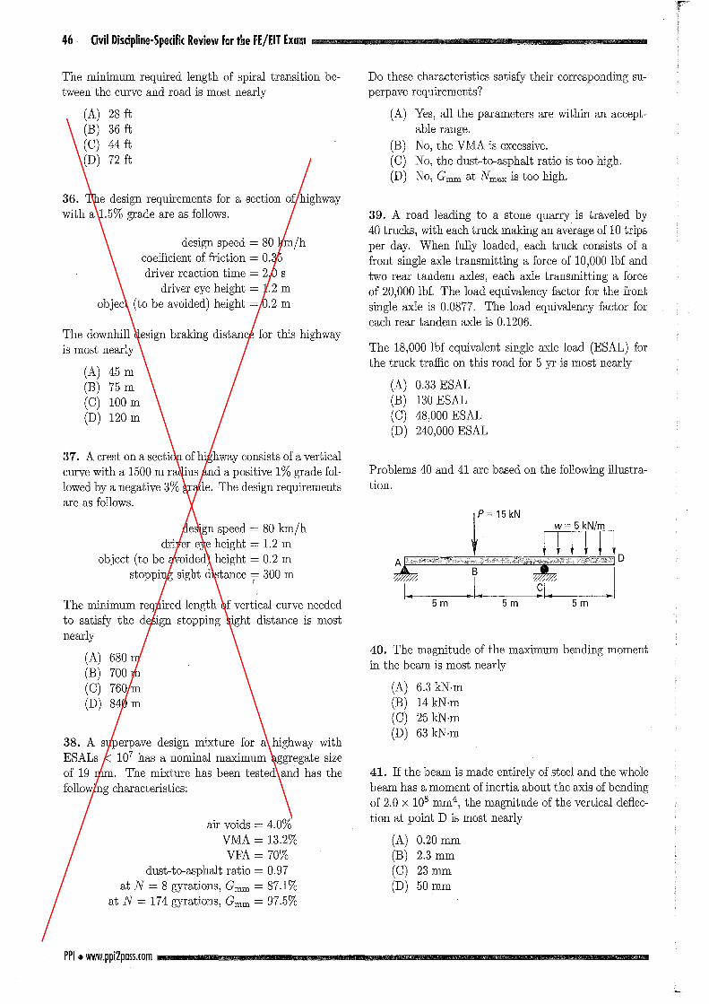
FJT:;矛;;「40. The magnitude of七hemaximum bending moment
in the beam is most nearly
(A) 6.3 kN-m
(B) 14凶 m
(0) 25 kN.m
(D) 63 kN-m
41. If the beam is made entirely of steel and the whole beam has a moment of inertia about the axis of bending
of 2.0 X 108 mm4, the magnitude of the vertical defl_ec-
tion at point D is most nearly
(A) 0.20 mm
(B) 2.3 m m
(0) 23 m m
(D) 50 mm
Prlldice b:llm 1 47
Problems 42 and 43 are based on the following informa-
tion and illustra七ion.
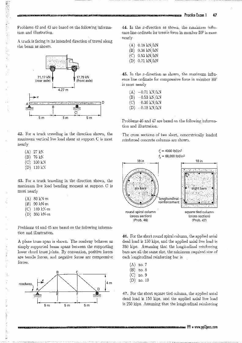
A truck is facing in its intended direction of travel along
the beam as shown.
トx
下予 lfm 手ょ :iD
42. For a truck traveling in the direction shown,七he
ma.ximum verもicalliveload shear at suppor七Cis most
nearly
(A) 27 kN
(B) 76 kN
(C) 100 kN
(D) 110凶
43. For a truck traveling in the direction shownう the
ma.ximum live load bending moment 抗 supportC is most ne紅 ly
(A) 80 kN-m
(B) 90 kN.m (C) 140 kN.m
(D) 360 kN.m
Problems 44 and 45 are based Dn the following informa-
tion and illustration.
A plane truss span is shown. The roadway behaves as
simply supported beam spans between the supporting
lower chord truss joints. By convention, positive forces
are tensile forcesう andnegative forces are compressive
forces.
m
A『
IaTill--47
「F5m 5m 5m
44. In the x-direction as shown, the ma.ximum influ-ence line ordinate for tensile force in member BF is most
nearly
(A) 0.18 kN/kN
(B) 0.36 kN/kN
(C) 0.53 kN/kN
(D) 0.71 kN/kN
45. In the x-direction as shown, the ma.ximum influ-ence line ordinate for compressive force in member BF
is most nearly
(A) -0.71悶 /kN
(B) -0.53 kN/凶(C) -0却 kN/kN
(D) -0.18 kN/kN
Problems 46 and 47 are based on the following informa-
tion and illustra七ion.
The cross sections of two short, concentrically loaded reinforced concrete columns are shown.
だ=4000 Ibf/in2
fy = 60,000 Ibf/in2
18 in 18in
longitundinal reinforcement
round spiral column (cross section) (Prob圃 46)
square tied column (cross section) (Prob.47)
46. For the short round spiral column, the applied a.xial dead load is 150 kips, and the applied a.xiallive load is 350 kips. Assuming that the longitudinal reinforcing
bars are all the same size, the minimum required size of
each longitudinal reinforcing bar is
(A) no.7
(B) no.8
(C) no. 9
(D) no. 10
47. For the short square tied column, the applied a.xial dead load is 150 kips, and the applied a.xial live load is 250 kips. Assuming tha七七helongitudinal reinforcing
PPI.附 w.ppi2pass.com
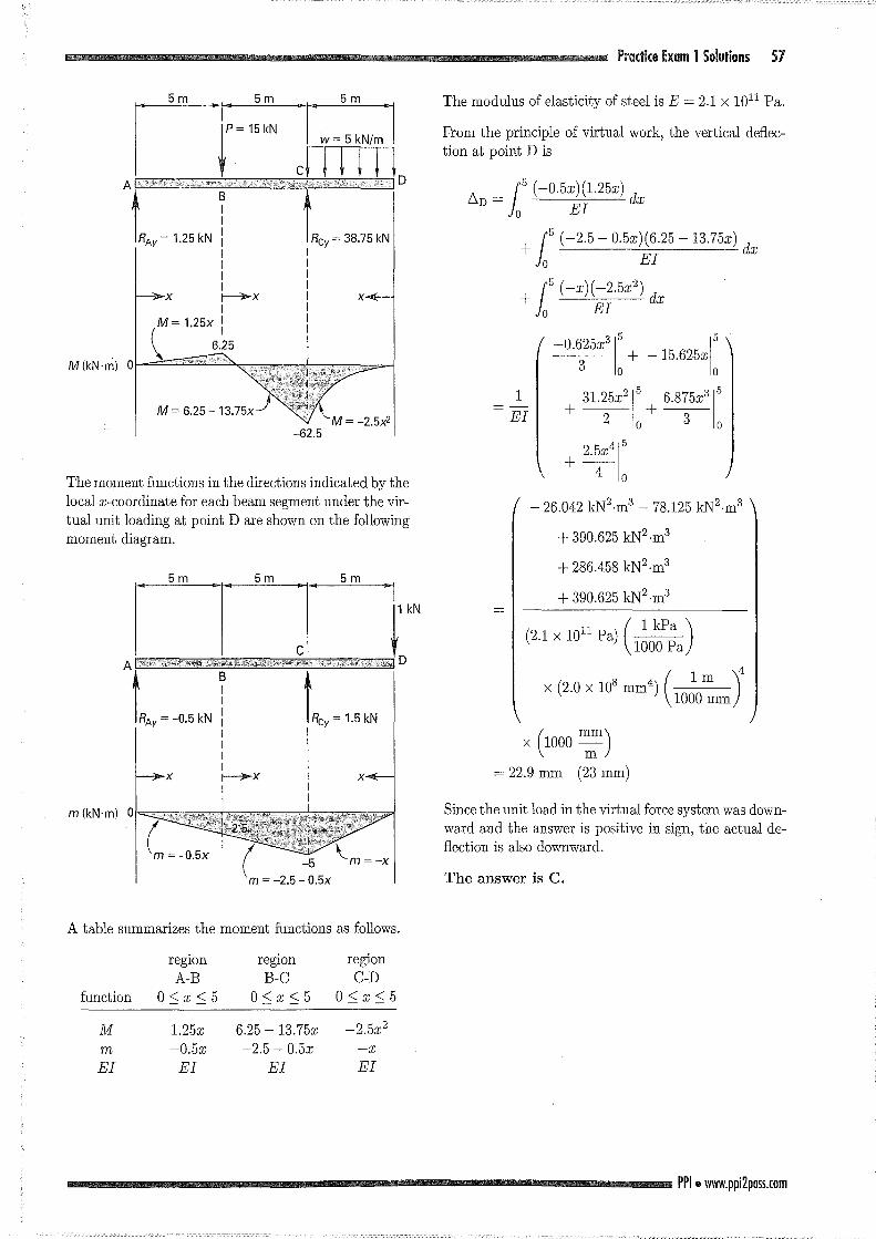
The moment functions in the directions indicated by
the 1oca1 x-coordinate for each beam segment under the
乱ctua110adingare shown on the following moment dia同
41. Use the princip1e of virtua1 work to五nd七hevertica1
de丑ectionat point D.
1S
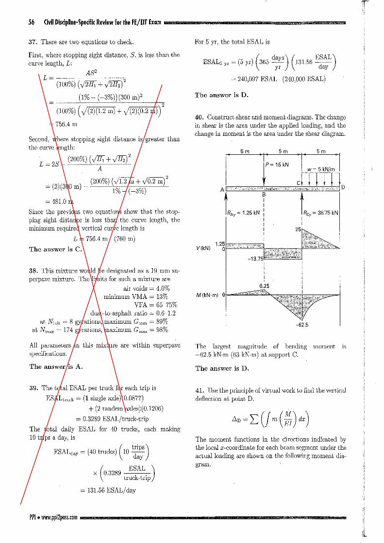
40. Construct shear and mome凶 diagrams.The change
in shear is the area under the applied 1oading, and the change in mome凶 isthe area under七heshear diagram.
N|一:-1
札 rニ州
江lOment
(240,000 ESAL)
ムD=~(J m(自白)
-62.5
The 1argest magnitude of bending
-62.5 kN.m (63 kN-m) at support C.
= 240う097ESAL
For 5 yr, the tota1 ESAL is
M川
IVA
whu
ν
I
E
q
4
J
A
-
-q 川一
y
ベー一
A
h一
一
円
円
トL』且晶
mill--
A
The answer is D.
The answer is D.
M{kN.m) 0
gram.
V{kN)
39. The tota1 ESAL per truck for each trip is
ESAL七r叫=(1 sing1e砿 1e)(0.0877)
+ (2 tandem ax1es)(0.1206) = 0.3289 ESALjtruck-trip
The tota1 daily ESAL for 40 trucks, each making 10 trips a day, is
All parameters in this mixture are within superpave
specifica七ions.
Second, where stopping sigh七distanceis greater than
the curve 1eng七h:
(200%) (VHi +♂'2/ L=2S A
Since也eprevious two equations show that the stop-
ping sight distance is 1ess than the curve 1ength, the minimum required vertica1 curve 1ength is
L = 756.4 m (760 m)
38. This mixture wou1d be designated as a 19 mm su伺
perpave mixture. The limits for such a mixture are
air voids = 4.0%
minimum VMλ= 13%
VFA = 65-75%
dusιto-aspha1t ratio = 0.6-1.2
at Ninit = 8 gyratiorおう maximumGmm = 89%
at Nmax = 174 gyrations, maximum Gmm = 98%
First, where s七oppingsigh七distance,8, is 1ess than the curve 1engthうL:
(200%) (Vl五五+VO万五:)2= (2)(300 m)一
1%-(-3%)
L= A82
-
(100%) (VWi +伊豆;y(1%一(-3%))(300m)2
一 (100%)(何日早川南可f
Civil Disdpline-Specific Review for the FE/日TEx田町1
E叫=山cks)(10寄)X (0印刷)
truckωtrip
= 131.56 ESALjday
3'7. There are two equa七ionsto check.
The answer is A.
The answer is C.
= 756.4 m
PPI.州 w.ppi2pass.com
= 481.0 m
56
X X
M(kN.m} 0
M= 6.25-
The moment functions in七hedirections indicated by the
local x-coordinate for each beam segment under the vir-
tual unit loading at point D are shown on the following
momen七diagram.
A table summarizes the moment functions as follows.
reglOn regron reglOn
A-B B同 C C自D
function 0<x<5 0<x<5 0<x<5
M 1.25x 6.25 -13.75x -2.5x2
m -0.5x -2.5 -0.5x -x
EI EI EI EI
Pr目cticeExam 1 Solufions 57
The modulus of elasticity of steel is E = 2.1 X 10¹¹ Pa.
From the principle of virtual work, the vertical defl.ec-tion at poin七Dis
ムD= 15
(- EI
+J EI
イー云 2
呼判:+一山1:I
EI 十半1:十平1:
十年1:
-26.042 kN2.m3 -78.125 kN2.m3
十 390.625 日~2.m3
+ 286.458 kN2.m3
十390.625kN2.m3
(2.1 X 10¹¹
Pa) (品)
/紅l立1¥X I llJlJU -一一ー l
¥ m /
= 22.9 mm (23 mm)
Since the unit load in the virtual force system was down-
ward and the answer is positive in sign, the actual de-fl.ection is also downward.
The answer is C.
PPI.附 w.ppi2poss.com
58 Civil Discipline-Specific Review for the FEjEIT Exam
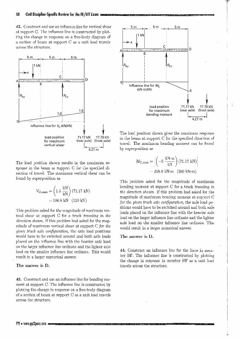
42. Construct and use an in丑uenceline for verもicalshear at support C. The in乱uenceline is constructed by plot-
ting the change in response on a free四 bodydiagram of
a section of beam at suppo吋 Cas a unit load travels
across the structure.
。
74 5m 5m
influence line for Vc (kN/kN)
load position for maximum vertical shear
1.5
t t 71.17 kN 17.79 kN
1 _ 1
The load position shown results in出emaximum re司
sponse in the beam at suppor七Cfor出especi五eddi-
rection of travel. The maximum vertical shear can be
found by superposition回
日 x=(1.5 ~~) (71.17凶)
This problem asked for the magnitude of maximum ver-
tical shear at support C for a truck tnαveling in the direction shown. If this problem had asked for the mag-nitude of maximum vertical shear at support C for the given truckαxle configur,αtion, the axle load posi七ionswould have to be switched around and both axle loads
placed on the infiuence line with the heavier axle load
on the larger infiuence line ordinate and the lighter axle
load on the smaller in丑uenceline ordinate. This would
result in a larger numerical answer.
The answer is D.
43. Construct and use an infiuence line for bending mo-
ment 抗日uppo凶 C.The in丑uenceline is constructed by
plotting the change in r田 ponseon a丘ee四 bodydiagram
of a section of beam at support C as a unit load travels
across七hestructure.
PPI.附 w.ppi2p日sS.com
。
load position for maximum
bending moment
t t
The load position shown gives the maximum response
in the beam at suppor七Cfor the speci五eddirec七ionof
travel. The maximum bending moment can be found
by superposition出
時 max= 1(-5守)川= 355.8 kN-m
This problem asked for the magnitude of maximum
bending moment at support C for a truck traveling in the direction shoωn. If this problem had asked for the magnitude of maximum bending moment at support C
for th巴giventruckαxle configurαtionうtheaxle load po-
sitions would have to be switched around and both axle
loads placed on the infiuence line with the heavier axle
load on the larger in宜uenceline ordinate and the lighter
axle load on the smaller in丑uenceline ordinate. This
would result in a larger numerical answer.
The answer is D.
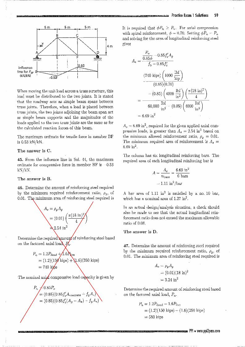
44. Construct an infiuence line for the force in mem-ber BF. The in丑uenceline is constructed by plotting
the change in response in member BF as a unit load
travels across the structure.
_J.,"
ゆ E;fd務
lllJzr J i iλ哩~I(附/kJ
When moving the uni七loadacross a truss structure, this
load must be disむibutedto the two joints. It is stated
七hatthe roadway acts as simple beam spans between
truss join七s.Therefore, when a load is placed between
truss join七s,the two joints adjoining the beam span act as simple beam supports and the magni加desof the
loads applied to出etwo truss joints are the same as for
the calculated reaction forces of七hisbeam.
The maximum ordinate for tensile force in member BF
is 0.53 kN /kN
The answer is C.
45. From the infl.uence line in 801. 44, the maximum ordinate for compressive force in member BF is -0.53
kN/kN
The answer Is B.
46. Determine the amount of reinforcing s七eelrequired
by the minimum required reinforcement ratio, Pg, of 0.01. The minimum area of reinforcing s七eelrequired is
= (0川(年)
Determine the required amount of reinforcing steel based
on the factored axialload, Pu.
Puニ1.2Pdead+ 1.6P!ive ヱ(1.2)(150kips) + (1.6)(350 kips) = 740 kips
The nominal axial compressive load capacity is given by
凡 =0.85P.。
= (0.85)(0.85f~Aconcrete +んAs)
= (0部 )(0.85五(Ag-As) +んAs)
Pr目di(eExam 1 Solutiolls S9
I七isrequired thatゆPn2: Pu. For axial compression
with spiral reinforcement,ゆ=0.70. 8ettingゆPn= P,叫
and solving for the area of longitudinal reinforcing steel
gIVes
山 ps)(10002)
485) (4000主)(年)。主一(0.85)(4000 ~~;)
As = 6.69 in2, required for the given applied axial com-pressive loads, is greater than As = 2.54 in2 based on
the minimum allowed reinforcement ratio, Pg = 0.01. The minimum required area of reinforcement is As二
6司69in2.
The column has six longitudinal reinforcing bars. The
required area of each longi七udinalreinforcing bar is
A=~ 一日主主一-nbars 6 bars
= 1.11 in2/bar
A bar area of 1.11 in2 is satisfied by a no. 10 bar, which has a nominal area of 1.27 in2.
In an actual design/ analysis situation,乱 checkshould
also be made to see that the actual longitudinal rein-
forcement ratio does not exceed the maximum allowable
ratio of 0.08.
The answer is D.
47. Determine the amount of reinforcing steel required
by the minimum required reinforcement ratio,内, of
0.01. The minimum area of reinforcing steel required is
As = pgAg
= (0.01)(18 in)2
= 3.24 in2
Determine the required amoun七ofreinforcing steel based
on the factored axi,al loadう Pu.
Pu = 1.2Pde吋+1.6P!ive
= (1.2) (150 kips) + (1.6) (250 kips) = 580 kips
PPI.附 w.ppi2p日sS.com

70 Civil Discipli鵬闘SpedficReview for the FE/EIT Ex脚
The七ra伍cflow relationship is given by q = kv, in which
q is the tra伍cvolume in veh/hr. The maximum tra伍c
volume for七hisroad is most nearly
(A) 760 veh/hr
(B) 880 veh/hr
(C) 900 veh/hr
(D) 960 veh/hr
38. The s七oppingsight dis七anceis 430 ft for a design
speed of 50 mph on a section of highway. The grades
for this highway section are -1% followed by 3%. The
required length of vertical curve needed to satisfy七he
AASHTO stopping sight distance for this design speed
is most nearly
(A) 270氏
(B) 380氏
(C) 410 ft
(D) 450 ft
39. A one-lane rural road has a 100 curve extending for
230 m along its centerline. The road is 5 m wide with
3 m wide shoulders. The design speed for this road is
75 km/h.
The superelevation needed so that side friction is not
needed is most nearly
(A) 0.00050
(B) 0.034
(C) 1.1 (D) 1.9
40. The worn surface course of a high-volume pave四
ment is being replaced with a design requiring a total
structural number of 6.6. The engineer has decided to
replace 6 in of the surface with recycled-in-place asphalt
concrete having a surface course strength coe血cientof
0.42, leaving in place 3 in of sound original pavement
having a strength coefficient of 0.3. Under the origi-
nal pavement are a 10 in ceme凶-treatedbase having
a strength coe血cientof 0.20ぅand阻 8in sandy gravel
subbase. What is the minimum strength coefficient for
the subbase?
(A) 0.05
(B) 0.10
(C) 0.15
(D) 0.20
PPI .州w.ppi2p日sS.com
Problems 41 and 42 are based on the following informa-tion and illustration.
The beam shown is loaded with two 1000 N point loads. The separation is maintained抗 2m, but出eloads may
be moved to any location on the be乱m.
h
門…什「一助|
蕩Z,
10 m 10 m
41. The maximum value for shear at support A is most
nearly
(A) 2000 N (B) 2800 N (C) 3000 N (D) 3800 N
42. The maximum value for moment at suppor七Ais
most nearly
(A) 1.8 kN.m (B) 8.0 kN-m
(C) 10 kN.m (D) 18 kN-m
43. A triangular pin-connected truss carries a load of
4448 N as shown. Each member has the same modulus
of elasticity and cross-sectional area.
:%:l M
3.0 m
P
N
4448 N
4.6 m
The truss member properties are E = 200 X 106 kPa and Aニ 2580.6mm2. The vertical deflection at point
P is most nearly
(A) 0.25 mm
(B) 0.48 mm
(C) 0.51 mm (D) 0.75 mm
Problems 44-46 are based on the following illustration.
l~ ~ ~ ~ ~ ~ ~ ~ ~ ~ ~ ~ ~ ~ L~ A 易 易
3m 3m
44. If the reaction at support A is 18.75 N, the reaction
at each of出eouter supports is most nearly
(A) 5.6 N
(B) 7.2 N (C) 11 N (D) 14 N
45. The maximum value of vertical shear at any point
along the beam is mos七nearly
(A) 4.7 N (B) 9.4 N (C) 14 N (D) 18 N
46. The maximum value of moment at any point along
the beam is mos七nearly
(A) 1.2 N.m (B) 3.1 N.m
(C) 4.6 N.m
(D) 5.7 N.m
Pr目diceEx園田12 71
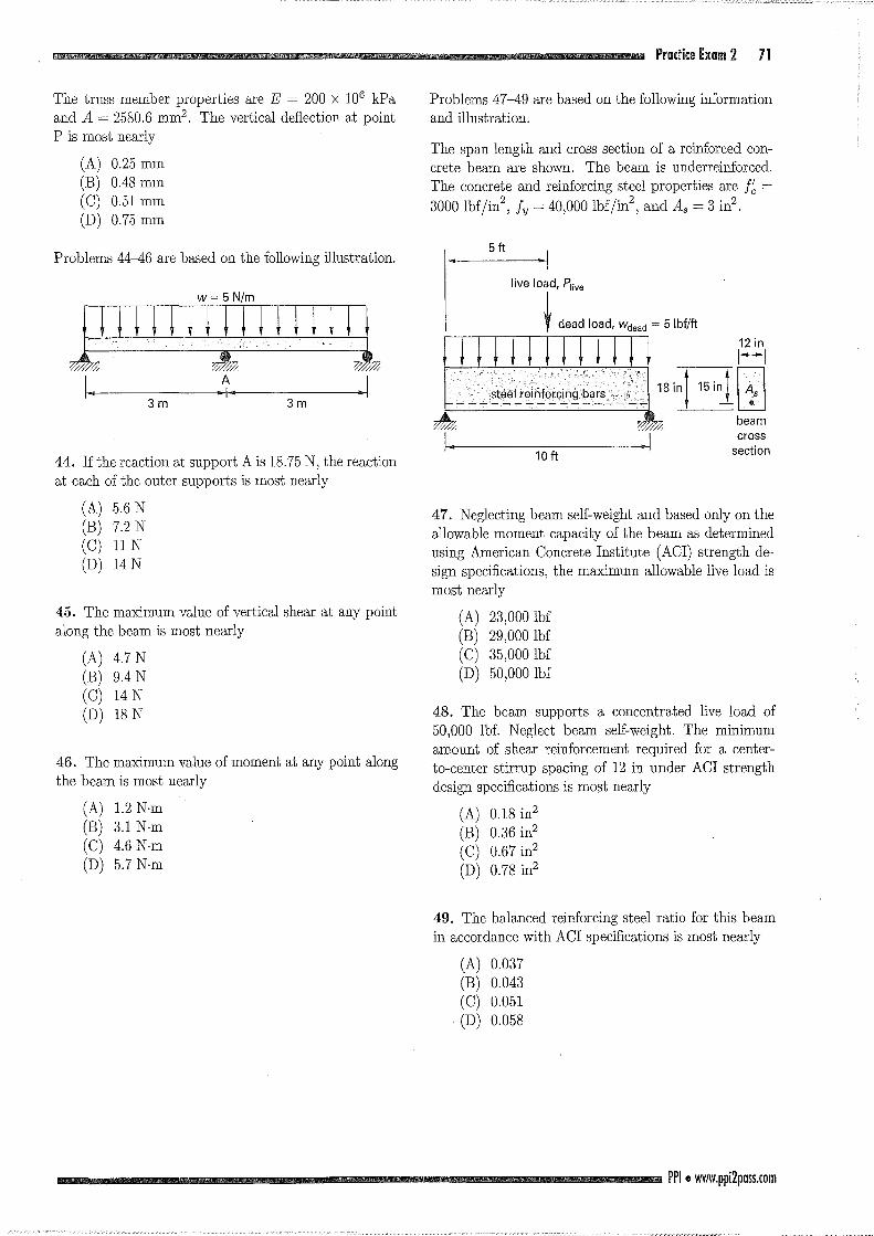
Problems 47-49 are based on the following information
and illustration.
The span length and cross section of a reinforced con-
crete beam are shown. The beam is underreinforced.
The concrete and reinforcing steel propertiesぽ e五=3000 lbf/in
2うん =40,000 lbf/in2, and As = 3 in2
•
6ft
10 ft
18 i日目beam
cross section
47. Neglec七ingbeam self-weight and based only on the
allowable moment capacity of the beam as determined
using American Concrete Institute (ACI) strength de白
sign specificationsう themaximum allowable live load is
most nearly
(A) 23,000 lbf (B) 29,000脳
(C) 35,000 lbf (D) 50,000 lbf
48. The beam supports a concentraもedlive load of
50,000 lbf. Neglec七beamself-weight. The minimum
amoun七ofshear reinforcement required for a center-
to-center stirrup spacing of 12 in under ACI strength
design specifications is most nearly
(A) 0.18 in2
(B) 0.36 in2
(C) 0.67 in2
(D) 0.78 in2
49. The balanced reinforcing steel ratio for this beam
in accordance with ACI specifications is most nearly
(A) 0.037 (B) 0.043
(C) 0.051
(D) 0.058
PPI.附 w.ppi2pass.com
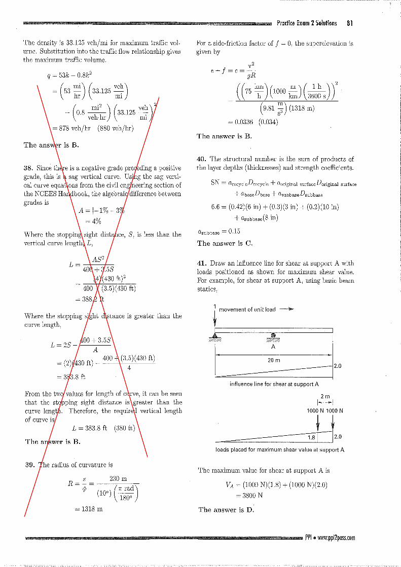
The density is 33.125 veh/mi for maximum tra缶cvol司
ume. Substitution in七othe tra白cflow relationship gives
the maximum tra血cvolume.
= (53 ::) (33.125 :~)
一 (0.8品)(33.1叫
The answer is B.
38. Since there is a negative grade preceding a positive
gradeう thisis a sag vertical curve. Using the sag verti-
cal curve equations from the civil engineering section of
the NCEES Handbook, the algebraic difference between
grades is
A = 1-1% 3%1
=4%
Where the stopping sight distance, 8, is less七han七he
vertical curve length, Lう
L=-竺L-400十 3.58
(4)(430 ft)2 400十 (3.5)(430此)
= 388.2 ft
Where the stopping sight distance is greater than the
curve leng七h,
400 + 3.58 L二 28一一 A一一
400 + (3.5)(430氏)= (2)(430此)-4
= 383.8 ft
From the七wovalues for length of curveうitcan be seen
that the s七oppingsight distance is greater than七he
curve length. Therefore, the required vertical length of curve is
L = 383.8抗 (380此)
The answer is B.
39. The radius of curvature is
R=~=川寺)
Pradice Ex日m2 501日tiol1S 81
For a side-台ictionfactor of f = 0, the superelevation is given by
((75引(1吋(品))(9.81 ~) (1318 m)
The answer is B.
40. The structural number is the sum of products of
the layer depths (thicknesses) and strength coe血cients.
SN=αrecycleDrecycle十αoriginalsurfaceD original surface
+αbaseDbase十αsubbaseDsubbase
6.6 = (0.42)(6 in) + (0.3)(3 in)十(0.2)(10 in)
十αsubbase(8in)
αsubbase = 0.15
The answer is C.
41. Draw an in丑uenceline for shear at suppor七Awith
loads positioned as shown for maximum shear value.
For exampleう forshear at support Aう usingbasic beam
statics,
20 m 2.0
influence line for shear at support A
ト--1
一一一:51~20loads placed for maximum shear value at support A
The maximum value for shear at support A is
VA = (1000 N)(1.8) + (1000 N)(2.0)
= 3800 N
The answer is D.
PPI.剛 w.ppi2p日sS.com
82 Civil Disdplille-Spedfic Review for the FEjEIT Ex日m
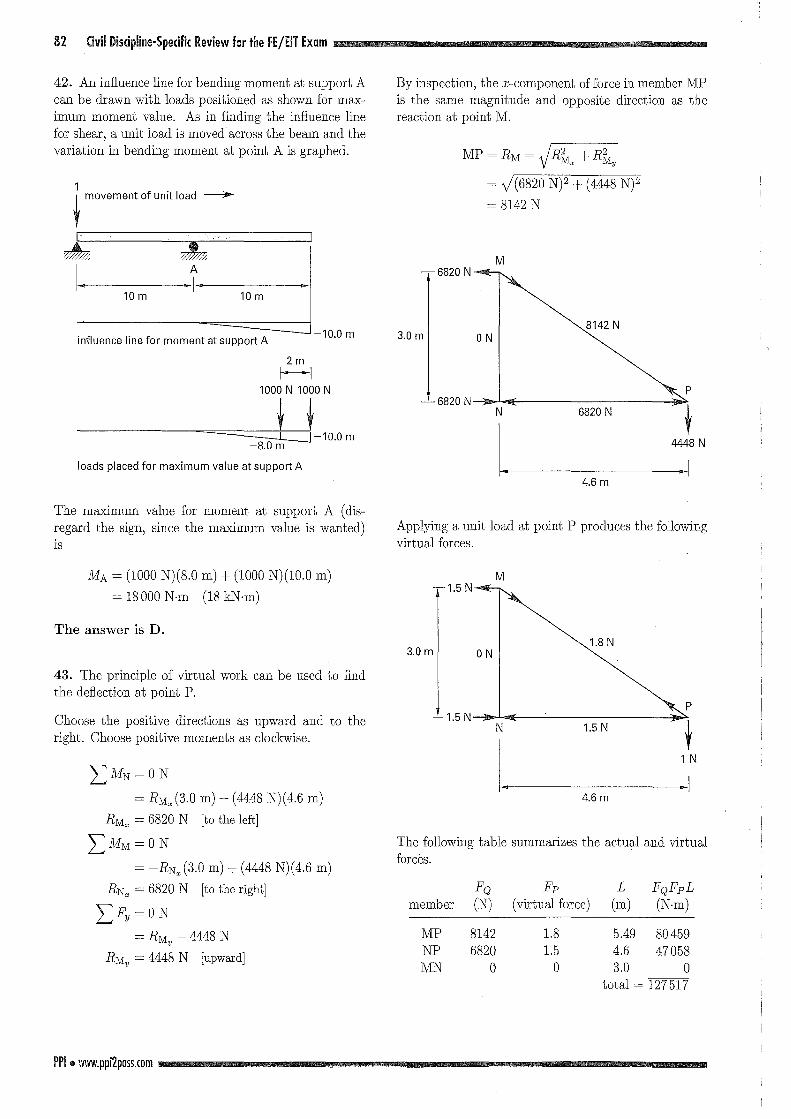
42. An infiuence line for bending moment at support A
can be drawn with loads positioned as shown for max-
imum mome凶 value. As in五nding七heinfiuence line
for shearう aunit load is moved across the beam and the
variation in bending moment at point A is graphed.
姦
10 m
す
mA
10 m
influence line for moment at support A
loads placed for maximum value at support A
The maximum value for moment at support A (dis-
regard the signぅ sincethe maximum value is wanted)
lS
MA = (1000 N)(8.0 m) + (1000 N)(10.0 m) 二 18000N.m (18 kN.m)
The answer is D.
43. The principle of virtual work can be used to find
the defiection a七poin七P.
Choose the positive directions as upward and to the
right. Choose positive moments as clockwise.
LMN=ON
= RM,,(3.0 m)十(4448N) (4.6 m)
RM" = 6820 N [七othe 1eft]
エMM=ON
= -RN" (3.0 m) + (4448 N)(4.6 m) RN" = 6820 N [to the right]
LFy =0 N
= RMy -
4448 N
RMν= 4448 N [upw乱rd]
PPI.附 W押i2p日sS.com
By inspection, the x-component of force in member MP
is the same magnitude and opposite direction as the
reaction at point M.
N
一
eU一
00
一
2Mで
4
一RI一弘
一十一イ、
一-m
一十
一〉dlu
一勺G
広明一向
41‘,一円U「|
二
一
白
川
M
伝山、必
R
U
v
剖
pi
M
M 一-6820N
8142 N 3.0 m ON
P 一一6820N
N 6820 N
4.6 m
Applying a unit load at point P produces the following
virtual forces.
M ....1.5N
1.8 N 3開OmI 0 N
P 1.5 N
N 1.5 N
4.6 m
The following table summarizes the actual and virtual
forces.
FQ member (N)
MP 8142
NP 6820
MN 0
Fp
(virtual force)
L
(m) FQFpL
(N-m)
1.8 1.5 0
5.49 80459
4.6 47058
3.0 0
total = 127517
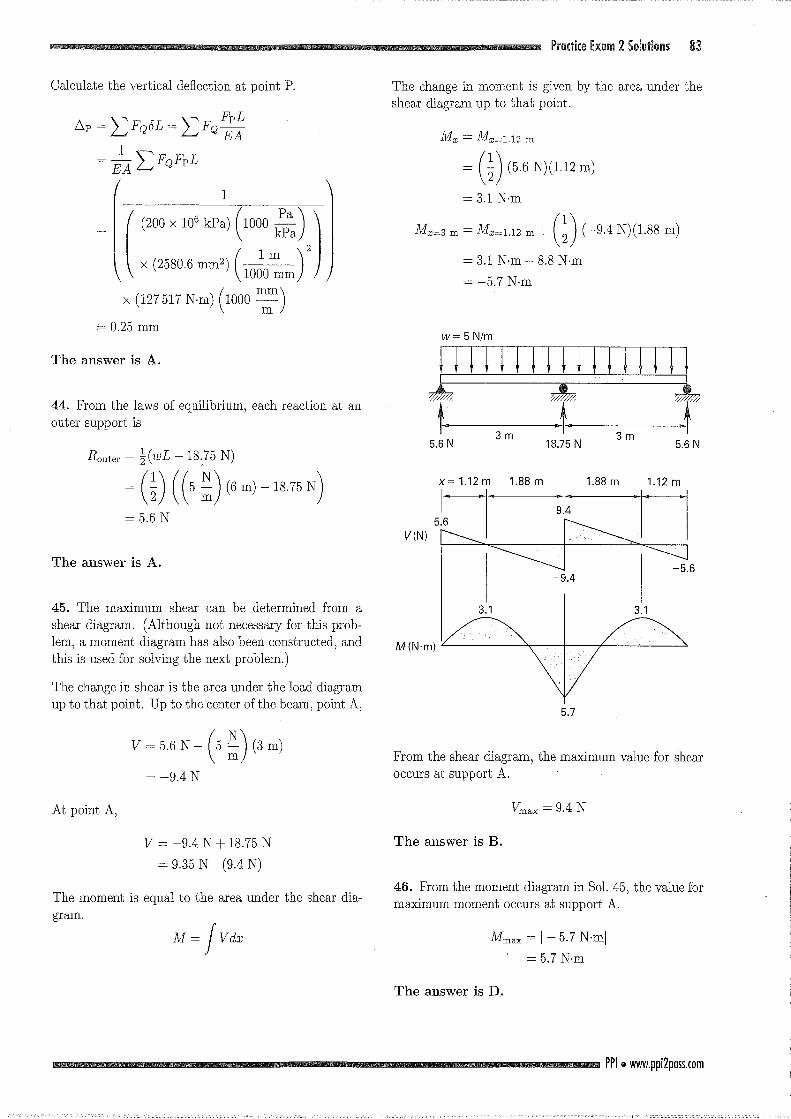
Calcu1ate the vertica1 de丑ection抗 pointP.
ムp= LFQ5L=玄FQ22=占LFQFpL
c川2却別ル一川Oω川い川O川山川1叩川O併6印刷叫叫)べ中(や1∞
x (2附 mm2)(抗日x (127517 N-m) (1000空)
The answer is A.
44. From the 1aws of equi1ibriumう eachreaction at an
outer suppor七is
ニ (t)((5 :)州-18同
The answer is A.
45. The maximum shear can be determined from a
shear diagram. (A1though no七necessaryfor this prob-
1em, a moment diagram has a1so been constructed, and this is used for solving the next prob1em.)
The change in shear is the area under the 10ad diagram
up to that point. Up to the center of the be叩 1,point A,
At poin七A,
ド 5.6N -(5 :) (3 m)
V = -9.4 N + 18.75 N = 9.35 N (9.4 N)
The moment is equa1 to the area under the shear dia-
gram.
Pr自ctic告Ex自m2 Soluti開 5 錦
The change in momenもisgiven by the area under七he
shear diagram up to that point.
= (t) (5.6叩 2m)
ル 3m =凡=1.12m十(訪問問問m)
??? x= 1.12 m 1.88 m 1司88m
3膚1 3.1
M(N'm)
5.7
From the shear diagram, the maximum va1ue for shear occurs 剖 supportA.
Vmax = 9.4 N
The answer is B.
46. From the moment diagram in 801. 45, the va1u巴formaximum moment occurs at support A.
Mmax = [-5.7 N.m[
= 5.7 N-m
The answer is D.
PPI e附 w.ppi2p日sS.com
哩50 Appendix Aftemoon Sa円lpleExamination
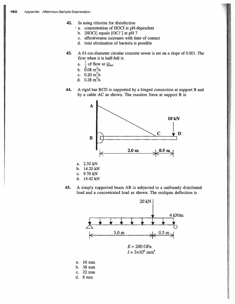
42. 1n using ch10rine for disinfection . a. concen住ationof HOC1 is pH-dependent b. [HOCl] equals [OCll at pH 7 c. e旺'ectivenessincreases with time of contact d. total elimination of bacteria is possible
43. A 61・cm-diametercircular concrete sewer is set on a slope of 0.00 l. The flow when it is halιfull is
ajof伽叫制lb. 0.08 m""/s c. 0.20 m
3/s
d. 0.28 m3/s
44. A rigid bar BCD is supported by a hinged connection at support B and by a cable AC as shown. The reaction force at support B is
A
D B
ド2.0m 、、レO.5m.. ..J
a. 2.50 kN b. 14.20 kN c. 9.70 kN d. 14.42 kN
45. A simply supported beam AB is subjected to a uniformly distributed load and a concentrated load as shown. The midspan def1ection is
20kN
ド 3.0m
E= 200 GPa
1= 3x106 mm4
a. 16mm b. 38 mm c. 22 mm d. 8mm
『
."
..
r--r・一一一一r-
[}=[]
Sample Exam 15.
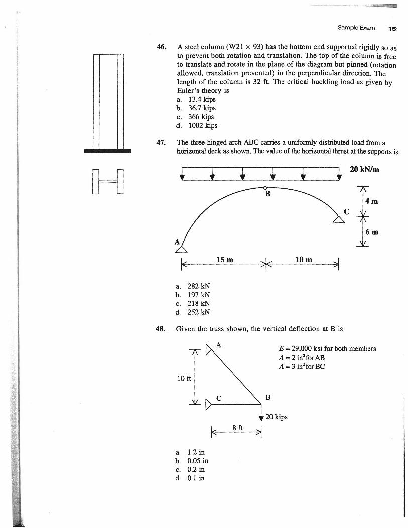
46. A steel column (W21 x 93) has the bottom end supported rigidly so as to prevent both rotation and translation. The top of the column is free to translate and rotate in出eplane of the diagram but pinned (rotation
allowed, translation prevented) in the perpendicular direction. The length of the column is 32 ft. The critical buckling load as given by Euler' s theory is
a. 13.4 kips b. 36.7 kips c. 366 kips
d. 1002 kips
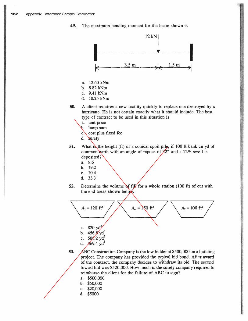
47. The three-hinged arch ABC carries a uniformly distributed load from a horizontal deck as shown.百levalue of the horizontal thrust at the supports is
ー
ド 15m 当6 10m オ
a. 282 kN b. 197 kN c. 218 kN d. 252 kN
48. Given the truss shown, the vertical deflection at B is
10抗
ド8 ft
a. 1.2 in b. 0.05 in c. 0.2 in d. 0.1 in
当|
B
E = 29,000 ksi for both members A = 2 in2for AB
A = 3 in2for BC
20 kips
152 Appendix Aftemoon Sample Examination
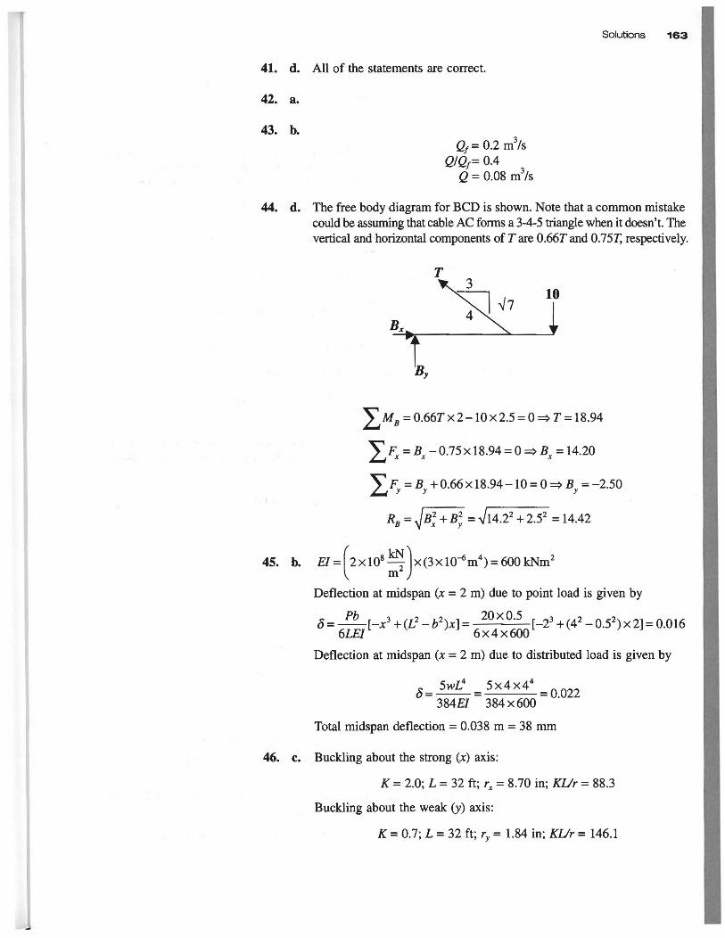
49. The maximum bending moment for the beam shown is
ド 3.5m ~〈 1.5 m
a. 12.60 kNm b. 8.82 kNm c. 9.41 kNm d. 10.25 kNm
50. A client requires a new faci1ity quickly to replace one destroyed by a hurricane. He is not certain exactly what it should include. The best type of contract to be used in出issituation is a. unit price b. lump sum c. cost plus fixed fee d. surety
51. What is the height (白)of a conical spoil pile, if 100 ft bank cu yd of common earth with an angle of repose of 320 and a 12% swell is deposited? a. 9.6 b. 19.2 c. 10.4 d. 33.3
52. Determine the volume of fi1l for a whole station (100 ft) of cut with the end areas shown below.
¥Al=120ft'/ ¥ι= 150が/¥A'=100 ft,/ a. 820 yd3
b.456.8ydj c. 506.2 yd
J
d. 569.4 ydJ
53. ABC Construction Company is the low bidder at $500,000 on a building project. The company has provided the typical bid bond. After award of the contract, the company decides to withdraw its bid. The second lowest bid was $520,000. How much is the sur~ty .company required to reimburse the client for the failure of ABC to sign? a. $500,000 b. $50,000 c. $20,000 d. $5000
Solutions 唱63
41. d. All of the statements are co町ect.
42. a.
43. b. Qf= 0.2 m
3/s
Q/Qf= 0.4 内
Q = 0.08 m'>/s
44. d. The free body diagram for BCD is shown. Note白ata common mistake couldbe脳出国ngthat cable AC forms a 3-4-5凶anglewhen it d<∞sn't.百leve同caland horizontal components of T訂eO.66T and 0.75T, respectively.
T
10
Bx
ヱMB=0.66Tx2-10x2.5=0司 T=ω4
ヱぇ=久一0.75x 18.94 = 0弓 Bx= 14.20
ヱπ=久+0“x18.94 -10 = 0 => By = -2.50
RB=石弓4
45. b. EI = r 2 xぽ型)X(3X1O-6m4) = 6∞kNm2
¥ m-J
Deflection at rnidspan (x = 2 m) due to point load is given by
Pb 三句今 20xO.5 _ _, o=一一一[-x
j
+(Llーか)x]= _ -~:. ~~:~ [-2j + (4l - OS) x 2] = 0.016
6LEr " 6x4xω。Deflection at rnidspan (x = 2 m) due to distributed load is given by
δ 5wL4
5x4x44
=一一=一一一一=0.022384EI 384x600
Total midspan deflection = 0.038 m = 38 mm
46. c. Buckling about the strong (x)鉱 is:
K = 2.0; L = 32 ft; rx = 8.70 in; KUr = 88.3
Buckling about the weak (y) axis:
K = 0.7; L = 32 ft; ry = 1.84 in; KUr = 146.1
唱64 Appendix Aftemoon Sample Examination
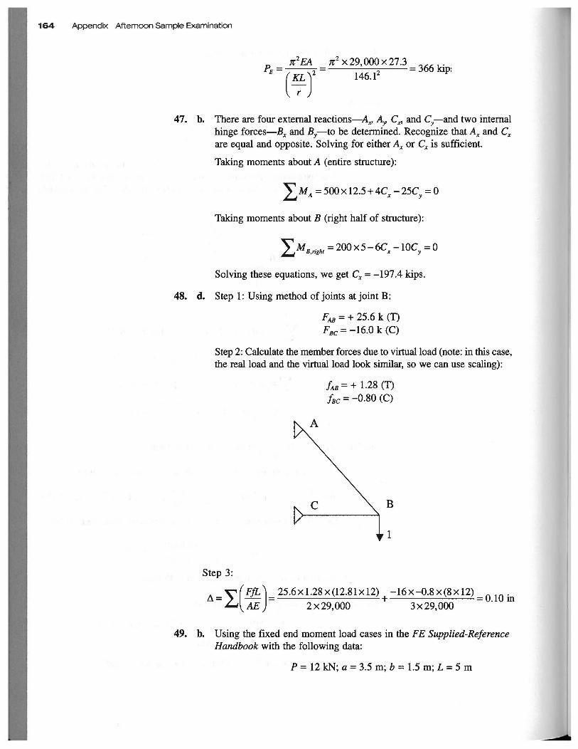
Rπ2EA π2 x29,000x273 内〆" .
=ナーーす= ヲ =jOO阻p:
(子}47. b. There are four extemal reactions-A_ A. c.. and C-and two intemal
x' "Y ~x'
hinge forces-Bx and By一旬 bedeterrnined. Recognize that Ax and Cx are equal and opposite. Solving for either Ax or Cx is sufficient.
Taking moments about A (entire structure):
ヱMA=500x山 +4ι-25Cy=0
Taking moments about B (right half of structure):
ヱMB.right= 200x5-6に一以=0
Solving these equations, we get Cx =ー197.4kips.
48. d. Step 1: U sing method of joints at joint B:
凡B= + 25.6 k (T)
FBC=ー16.0k (c)
Step 2: Calculate the member forces due to virtualload (note: in出iscase, 出e毘 alloadand the virtualload look similar, so we can use scaling):
Step 3:
んB= + 1.28 (T) fBC = -0.80 (c)
B
=すrFfL 1=~5似1.28x (12.81 x 12)+-16x-O.8x(8xI2L= 0.10血
""""'l AE ) 2x29.000 3x29.000
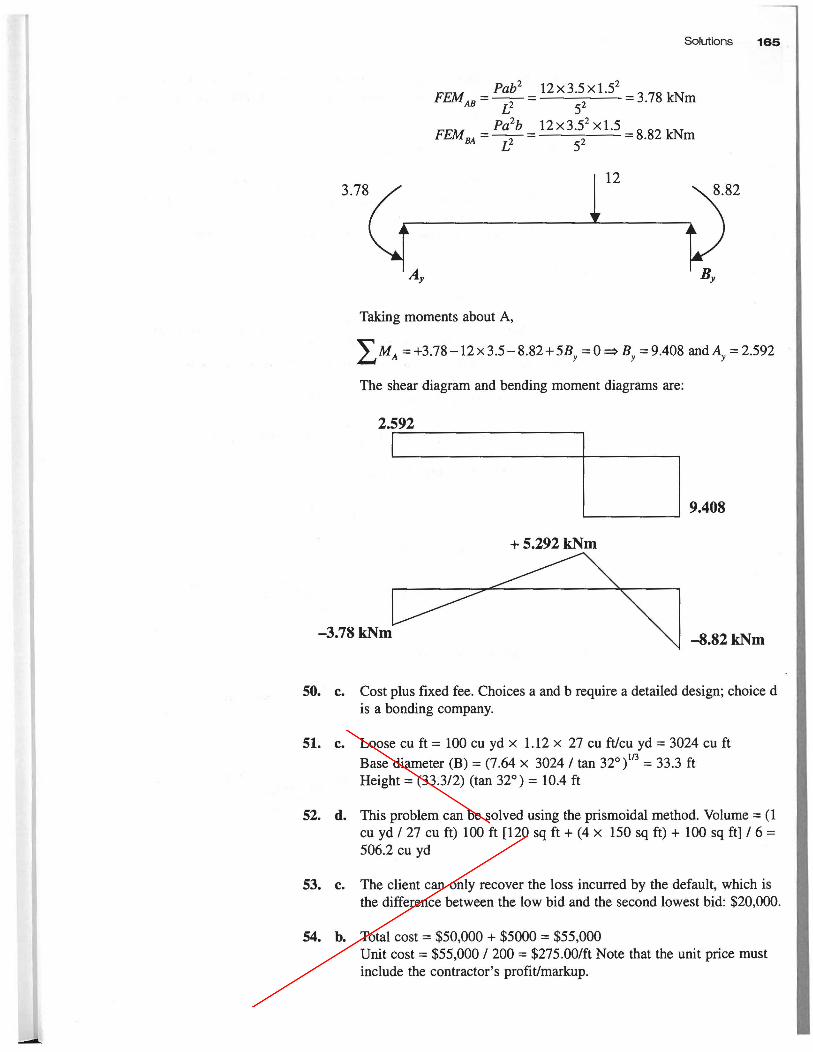
49. b. Using the fixed end moment load cases in白eFE Supplied-Rそference
Handbook with the following data:
P = 12 kN;α= 3.5 m; b = 1.5 m; L = 5 m
....
=-.:
Solutions 唱65
Pab2 12 x 3.5 x 1.52
=ーで一=--_._.__--_.-=3.78 kNrn AB 72 L~
Pa2b 12x3.52 x1.5 =ーで一=--_._.__ -._.-==8.82 kNrn BA r2 L~
12
Taking rnornents about A,
ヱMA=+3.78一以3.5-8.82+玖 =0叫 =9.408釦 dAy=2.592
The shear diagrarn and bending rnornent diagrarns紅 e:
2.592
9.408
+5.292 kNm
-3.78kNm -8.82kNm
50. c. Cost p1us fixed fee. Choices a and b require a detailed design; choice d is a bonding cornpany.
51. c. Loose cu ft = 100 cu yd x 1.12 x 27 cu ft/cu yd = 3024 cu ft
Base diarneter (B) == (7.64 x 3024/ tan 320 )1/3 = 33.3 ft
Height == (33.3/2) (tan 320) == 10.4 ft
52. d. 百1isproblern can be solved using the prisrnoidal rnethod. Vo1urne == (1 cu yd / 27 cu ft) 1∞ft [120 sq ft + (4 x 150 sq ft) + 100 sq ft] /6= 506.2 cu yd
53. c. The client can only recover the 10ss incurred by the default, which is 出edi百erencebetween the low bid and the second 10west bid: $20,000.
54. b. Total cost = $50,000 + $5000 == $55,000 Unit cost == $55,000/200 == $275.00/ft Note出atthe unit price rnust include the contractor's profit/rnarkup.
Determinacy and Stability
Determinacy and Stability I
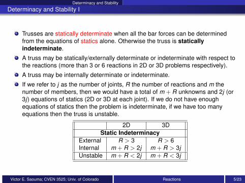
Trusses are statically determinate when all the bar forces can be determinedfrom the equations of statics alone. Otherwise the truss is staticallyindeterminate.
A truss may be statically/externally determinate or indeterminate with respect tothe reactions (more than 3 or 6 reactions in 2D or 3D problems respectively).
A truss may be internally determinate or indeterminate.
If we refer to j as the number of joints, R the number of reactions and m thenumber of members, then we would have a total of m + R unknowns and 2j (or3j) equations of statics (2D or 3D at each joint). If we do not have enoughequations of statics then the problem is indeterminate, if we have too manyequations then the truss is unstable.
2D 3DStatic Indeterminacy
External R > 3 R > 6Internal m + R > 2j m + R > 3jUnstable m + R < 2j m + R < 3j
Victor E. Saouma; CVEN 3525; Univ. of Colorado Reactions 5/23
Method of Joints
Method of Joints II
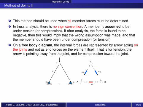
This method should be used when all member forces must be determined.
In truss analysis, there is no sign convention. A member is assumed to beunder tension (or compression). If after analysis, the force is found to benegative, then this would imply that the wrong assumption was made, and thatthe member should have been under compression (or tension).
On a free body diagram, the internal forces are represented by arrow acting onthe joints and not as end forces on the element itself. That is for tension, thearrow is pointing away from the joint, and for compression toward the joint.
cc
t
C
A B
-ve
+ve
-ve
A B
C
Victor E. Saouma; CVEN 3525; Univ. of Colorado Reactions 9/23
Example; Method of Joints
Example; Method of Joints I
AB C D
E
FG
H
128
20 k 40 k 40 k
10'
32'
24' 24' 24' 24'
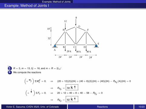
1 R = 3, m = 13, 2j = 16, and m + R = 2j√
2 We compute the reactions
(+
���)ΣMEz = 0; ⇒ (20 + 12)(3)(24) + (40 + 8)(2)(24) + (40)(24)− RAy (4)(24) = 0
⇒ RAy = 58 k 6(+ ?
)ΣFy = 0; ⇒ 20 + 12 + 40 + 8 + 40− 58− REy = 0
⇒ REy = 62 k 6
Victor E. Saouma; CVEN 3525; Univ. of Colorado Reactions 10/23
Example; Method of Joints
Example; Method of Joints II
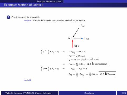
3 Consider each joint separately:
Node A: Clearly AH is under compression, and AB under tension.
58 k
FAB
FAH
A
(+ 6
)ΣFy = 0; ⇒ −FAHy + 58 = 0
FAH = lly
(FAHy )
ly = 32; l =√
322 + 242 = 40
⇒ FAH = 4032 (58) = 72.5 k Compression(
+-)
ΣFx = 0; ⇒ −FAHx + FAB = 0
FAB = LxLy
(FAHy ) = 2432 (58) = 43.5 k Tension
Node B:
Victor E. Saouma; CVEN 3525; Univ. of Colorado Reactions 11/23
Example; Method of Joints
Example; Method of Joints III
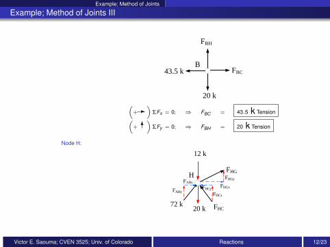
B
20 k
FBH
43.5 k FBC
(+-
)ΣFx = 0; ⇒ FBC = 43.5 k Tension(
+ 6)
ΣFy = 0; ⇒ FBH = 20 k Tension
Node H:
H
12 k
FHG
FHC72 k
20 k
FHCx
FHCyFAHy
FHGx
FHGyFAHx
Victor E. Saouma; CVEN 3525; Univ. of Colorado Reactions 12/23
Example; Method of Joints
Example; Method of Joints IV
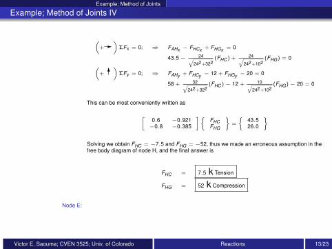
(+-
)ΣFx = 0; ⇒ FAHx − FHCx + FHGx = 0
43.5− 24√242+322
(FHC ) + 24√242+102
(FHG) = 0(+ 6
)ΣFy = 0; ⇒ FAHy + FHCy − 12 + FHGy − 20 = 0
58 + 32√242+322
(FHC )− 12 + 10√242+102
(FHG)− 20 = 0
This can be most conveniently written as
[0.6 −0.921−0.8 −0.385
]{FHCFHG
}=
{43.526.0
}
Solving we obtain FHC = −7.5 and FHG = −52, thus we made an erroneous assumption in thefree body diagram of node H, and the final answer is
FHC = 7.5 k Tension
FHG = 52 k Compression
Node E:
Victor E. Saouma; CVEN 3525; Univ. of Colorado Reactions 13/23
Example; Method of Joints
Example; Method of Joints V
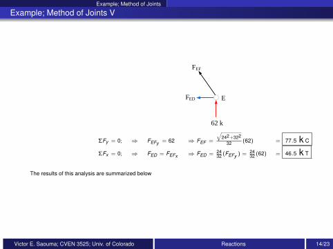
E
62 k
FED
FEF
ΣFy = 0; ⇒ FEFy = 62 ⇒ FEF =
√242+322
32 (62) = 77.5 k C
ΣFx = 0; ⇒ FED = FEFx ⇒ FED = 2432 (FEFy ) = 24
32 (62) = 46.5 k T
The results of this analysis are summarized below
Victor E. Saouma; CVEN 3525; Univ. of Colorado Reactions 14/23
Example; Method of Joints
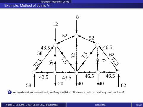
Example; Method of Joints VI
43.5 43.5 46.5 46.5
72.5 20
32 2.5
7.5 4 0 77.5
46.5
625843.5
52 52
58 62
128
20 40 40
4 We could check our calculations by verifying equilibrium of forces at a node not previously used, such as D
Victor E. Saouma; CVEN 3525; Univ. of Colorado Reactions 15/23
Examples Beams
Example Beam; 1
A
B C D
E
2 k/ft
4ft 4ft 4ft6ft
43
11 k 10 k
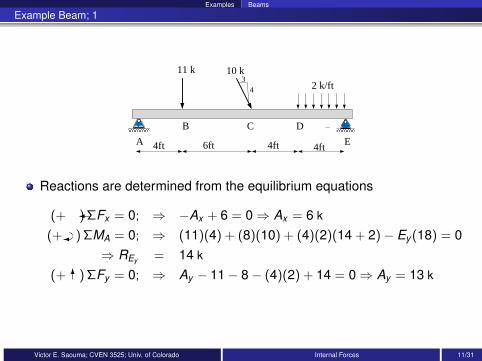
Reactions are determined from the equilibrium equations
(+ �) ΣFx = 0; ⇒ −Ax + 6 = 0⇒ Ax = 6 k
(+ ���) ΣMA = 0; ⇒ (11)(4) + (8)(10) + (4)(2)(14 + 2)− Ey (18) = 0⇒ REy = 14 k
(+ 6) ΣFy = 0; ⇒ Ay − 11− 8− (4)(2) + 14 = 0⇒ Ay = 13 k
Victor E. Saouma; CVEN 3525; Univ. of Colorado Internal Forces 11/31
Examples Beams
Example Beam; 2
A
B C D
E
2 k/ft
4ft 4ft 4ft6ft
43
11 k 10 k
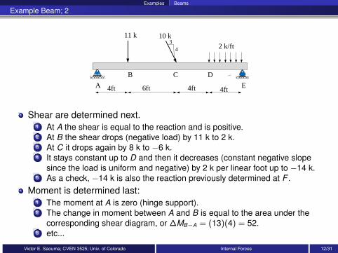
Shear are determined next.1 At A the shear is equal to the reaction and is positive.2 At B the shear drops (negative load) by 11 k to 2 k.3 At C it drops again by 8 k to −6 k.4 It stays constant up to D and then it decreases (constant negative slope
since the load is uniform and negative) by 2 k per linear foot up to −14 k.5 As a check, −14 k is also the reaction previously determined at F .
Moment is determined last:1 The moment at A is zero (hinge support).2 The change in moment between A and B is equal to the area under the
corresponding shear diagram, or ∆MB−A = (13)(4) = 52.3 etc...
Victor E. Saouma; CVEN 3525; Univ. of Colorado Internal Forces 12/31
Examples Beams
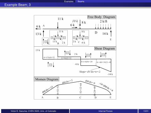
Example Beam; 3
A B C D E
2 k
-6 k
-14 kSlope= dV/dx=w=-2
dM/dx=+2 dM/dx=-6
0+
52=
52
52+
12=
64
64-2
4=
40
10 k
11 k
2 k13 k
8 k
2 k
A
BC
E
13 k
A=(13)(4)=52 A=(6)(2)=12
A=(-6)(4)=-24 A=-4(6+14)/2=-40
-6 k
Victor E. Saouma; CVEN 3525; Univ. of Colorado Internal Forces 13/31
arches Three Hinged Arch; Point Loads
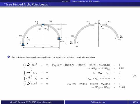
Three Hinged Arch; Point Loads I
80' 60'
33.75'
30'
20 k
B
80 k
26.25'A
C
20' 20'
20 k B30 k
80 k
A
C
HA
VA
VC
HC
VB VB
HB HB
30 k
Four unknowns, three equations of equilibrium, one equation of condition ⇒ statically determinate.
(
+���)
ΣMCz = 0; (RAy )(140) + (80)(3.75) − (30)(80) − (20)(40) + RAx (26.25) = 0
⇒ 140RAy + 26.25RAx = 2.900(
+-
)
ΣFx = 0; 80 − RAx − RCx = 0(
+ 6)
ΣFy = 0; RAy + RCy − 30 − 20 = 0(
+���)
ΣMBz = 0; (Rax )(60) − (80)(30) − (30)(20) + (RAy )(80) = 0
⇒ 80RAy + 60RAx = 3, 000
(22)
Victor E. Saouma; CVEN 3525; Univ. of Colorado Cables & Arches 19/24
arches Three Hinged Arch; Point Loads
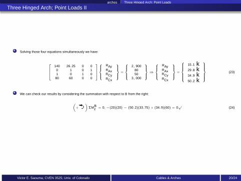
Three Hinged Arch; Point Loads II
Solving those four equations simultaneously we have:
140 26.25 0 00 1 0 11 0 1 0
80 60 0 0
RAyRAxRCyRCx
=
2, 9008050
3, 000
⇒
RAyRAxRCyRCx
=
15.1 k29.8 k34.9 k50.2 k
(23)
We can check our results by considering the summation with respect to B from the right:
(
+��
�)
ΣMBz = 0; −(20)(20) − (50.2)(33.75) + (34.9)(60) = 0
√(24)
Victor E. Saouma; CVEN 3525; Univ. of Colorado Cables & Arches 20/24
Examples Beam
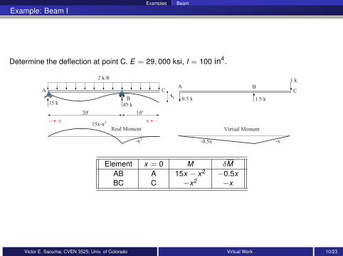
Example: Beam I
Determine the deflection at point C. E = 29, 000 ksi, I = 100 in4.
2 k/ft
AA B
B
C C
15 k 45 k
0.5 k 1.5 k
1 k
20' 10'
C
-x-0.5x
15x-x2
-x2
Real Moment Virtual Moment
x x
Element x = 0 M δMAB A 15x − x2 −0.5xBC C −x2 −x
Victor E. Saouma; CVEN 3525; Univ. of Colorado Virtual Work 10/23
Examples Beam
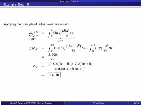
Example: Beam II
Applying the principle of virtual work, we obtain
∆CδP︸ ︷︷ ︸δW∗
=
∫ L
0δM(x)
M(x)
EIzdx︸ ︷︷ ︸
δU∗
(1)∆C =
∫ 20
0(−0.5x)
(15x − x2)
EIdx +
∫ 10
0(−x)
−x2
EIdx
=2, 500
EI
∆C =(2, 500) k − ft3(1, 728) in3/ ft3
(29, 000) ksi(100) in4
= 1.49 in
Victor E. Saouma; CVEN 3525; Univ. of Colorado Virtual Work 11/23
Examples Truss; Simple
Truss; Simple I
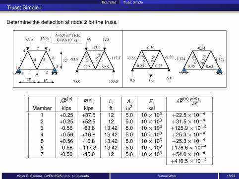
Determine the deflection at node 2 for the truss.
12'
1
1
3
4
4
7
5
2
3
5
60 k 120 k
6
12' 12'
A=5.0 in2
each;
E=10x103
ksi 60 120
-117.3-83.8
37.5 52.5
16.8
-16.
8
-45.0
75.0 105.0
A
-0.50
-0.56 -0.56
0.25 0.25
0.5
6
0.5
6
0.5 0.51.0
-0.54
-1.124-
1.574
0.45 0.63
0.2
26
-0.2
26
δP(e)
P(e), L, A, E , δP(e) P(e)L
AEMember kips kips ft in2 ksi
1 +0.25 +37.5 12 5.0 10 × 103 +22.5 × 10⁻⁴
2 +0.25 +52.5 12 5.0 10 × 103 +31.5 × 10⁻⁴
3 -0.56 -83.8 13.42 5.0 10 × 103 +125.9 × 10⁻⁴
4 +0.56 +16.8 13.42 5.0 10 × 103 +25.3 × 10⁻⁴
5 +0.56 -16.8 13.42 5.0 10 × 103 −25.3 × 10⁻⁴
6 -0.56 -117.3 13.42 5.0 10 × 103 +176.6 × 10⁻⁴
7 -0.50 -45.0 12 5.0 10 × 103 +54.0 × 10⁻⁴
+410.5 × 10⁻⁴
Victor E. Saouma; CVEN 3525; Univ. of Colorado Virtual Work 18/23
Examples Truss; Simple
Truss; Simple II
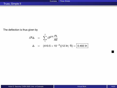
The deflection is thus given by
δP∆ =7∑1
δP(e) PL
AE
∆ = (410.5 × 10⁻⁴)(12 in/ ft) = 0.493 in
Victor E. Saouma; CVEN 3525; Univ. of Colorado Virtual Work 19/23
Examples Truss with initial camber
Truss with initial camber I
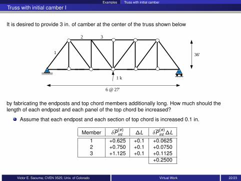
It is desired to provide 3 in. of camber at the center of the truss shown below
1
32
6 @ 27'
1 k
36'
by fabricating the endposts and top chord members additionally long. How much should thelength of each endpost and each panel of the top chord be increased?
Assume that each endpost and each section of top chord is increased 0.1 in.
Member δP(e)int ∆L δP
(e)int ∆L
1 +0.625 +0.1 +0.06252 +0.750 +0.1 +0.07503 +1.125 +0.1 +0.1125
+0.2500
Victor E. Saouma; CVEN 3525; Univ. of Colorado Virtual Work 22/23
Examples Truss with initial camber
Truss with initial camber II
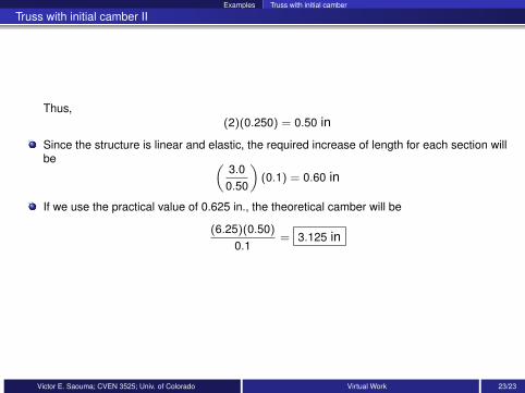
Thus,(2)(0.250) = 0.50 in
Since the structure is linear and elastic, the required increase of length for each section willbe (
3.00.50
)(0.1) = 0.60 in
If we use the practical value of 0.625 in., the theoretical camber will be
(6.25)(0.50)
0.1= 3.125 in
Victor E. Saouma; CVEN 3525; Univ. of Colorado Virtual Work 23/23
V. Saouma; CVEN‐3525 1
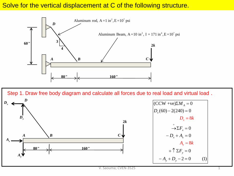
Solve for the vertical displacement at C of the following structure.
Step 1. Draw free body diagram and calculate all forces due to real load and virtual load .
A B C
80" 160"
D
2kyD
xD
xA
yA
(CCW +ve) 0(60) 2(240) 0
00
0
2
8
0 (1)
8
A
x
x
x x
y
y y
x
x
MD
FD A
F
A D
D k
A k
+
Σ =− =
→Σ =
− + =
+ ↑ Σ =
− =
=
− +
=
A B C
2k
80" 160"
3
4
D2 7Aluminum rod, A =1 in ,E =10 psi
2 4 7Aluminum Beam, A =10 in , I = 171 in ,E =10 psi
60"
V. Saouma; CVEN‐3525 2
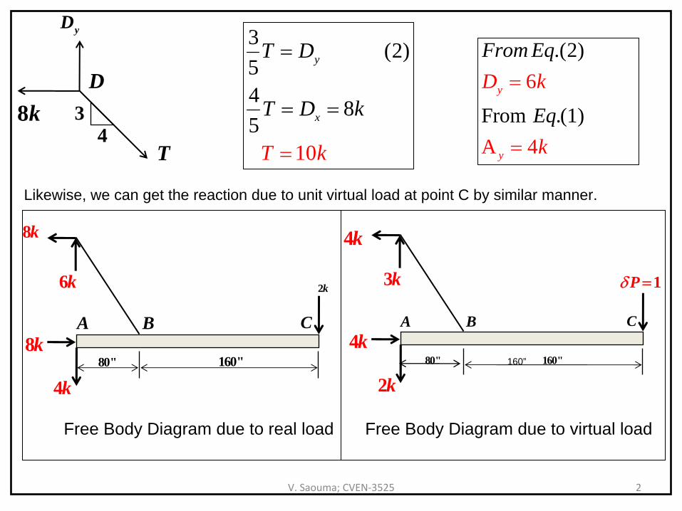
D
yD
8k 34
T
3 (2)54
15
0
8
y
x
T D
T
k
D k
T
=
=
=
=
.(2)
From .(4
1)
6
A
y
y
From Eq
Eq
D k
k
=
=
Likewise, we can get the reaction due to unit virtual load at point C by similar manner.
A B C
80" 160"
2k6k
8k
8k
4k
A B C
80" 160"
1Pδ =3k
4k
4k
2k
Free Body Diagram due to real load Free Body Diagram due to virtual load
160”
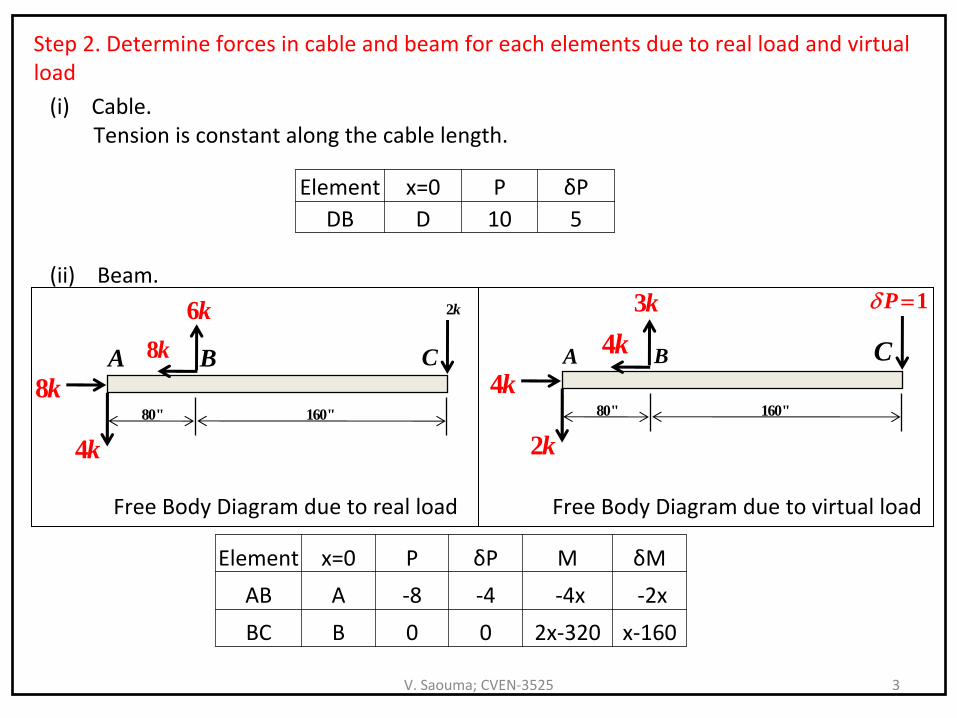
V. Saouma; CVEN‐3525 3
Element x=0 P δPDB D 10 5
Step 2. Determine forces in cable and beam for each elements due
to real load and virtual
load(i)
Cable. Tension is constant along the cable length.
(ii) Beam.
A B C
80" 160"
2k6k8k
8k
4k
A B C
80" 160"
1Pδ =3k4k
4k
2k
Free Body Diagram due to real load Free Body Diagram due to virtual load
Element x=0 P δP M δM
AB A ‐8 ‐4 ‐4x ‐2x
BC B 0 0 2x‐320 x‐160
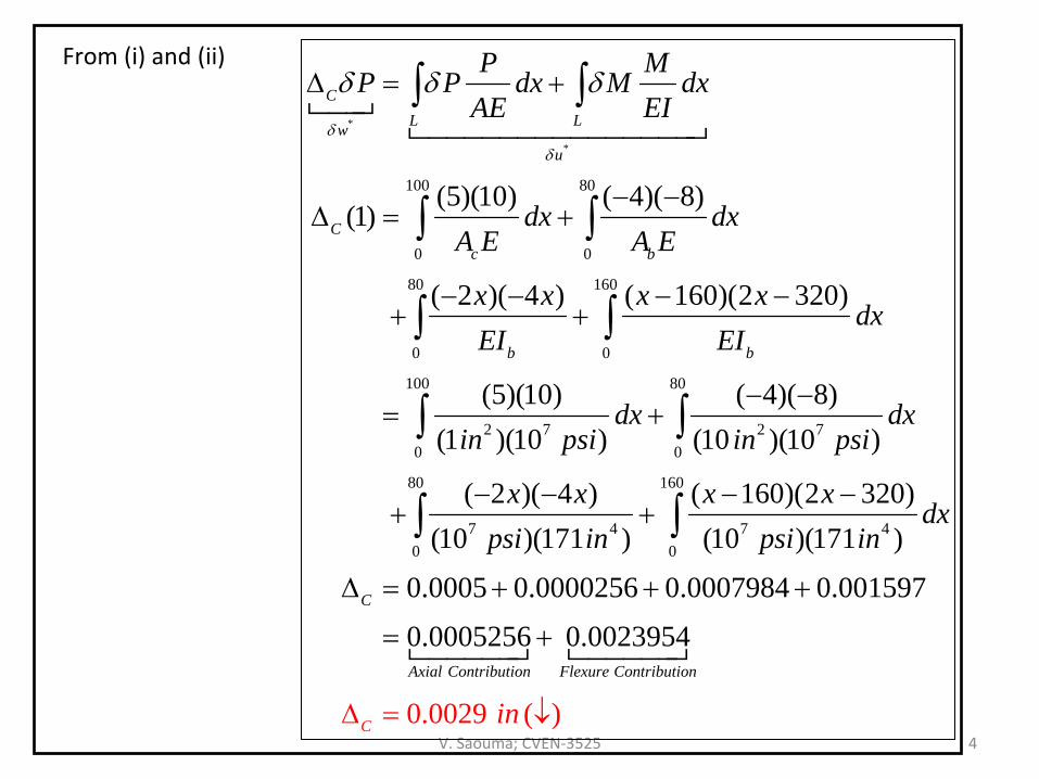
V. Saouma; CVEN‐3525 4
From (i) and (ii)
*
*
100 80
0 0
80 160
0 0
100 80
2 7 2 70 0
(5)(10) ( 4)( 8)(1)
( 2 )( 4 ) ( 160)(2 320)
(5)(10) ( 4)( 8)(1 )(10 ) (10 )(10 )
( 2
CL Lw
u
Cc b
b b
P MP P dx M dx
AE EI
dx dxA E A E
x x x xdx
EI EI
dx dxin psi in psi
x
δδ
δ δ δΔ = +
− −Δ = +
− − − −+ +
− −= +
−+
∫ ∫
∫ ∫
∫ ∫
∫ ∫80 160
7 4 7 40 0
)( 4 ) ( 160)(2 320)(10 )(171 ) (10 )(171 )
0.0005 0.0000256 0.0007984 0.001597
0.0005256 0
0
.
.
00
00
239
)
54
29 (
C
Axial Contribution Flexure Contrib t
C
u ion
x x xdx
psi in p i i
n
n
i
s− − −
+
Δ = + + +
= +
Δ = ↓
∫ ∫
V. Saouma; CVEN‐3525 10
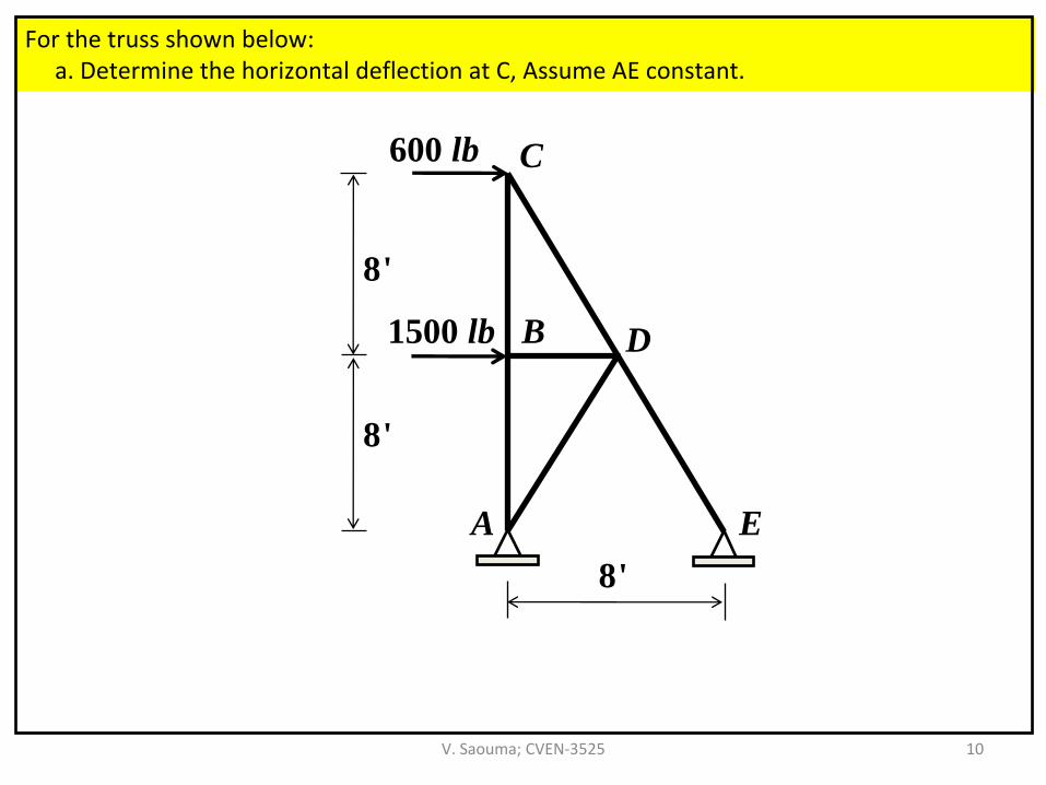
For the truss shown below:a. Determine the horizontal deflection at C, Assume AE constant.
A E
D
C
B
600 lb
1500 lb
8'
8'
8'
V. Saouma; CVEN‐3525 11
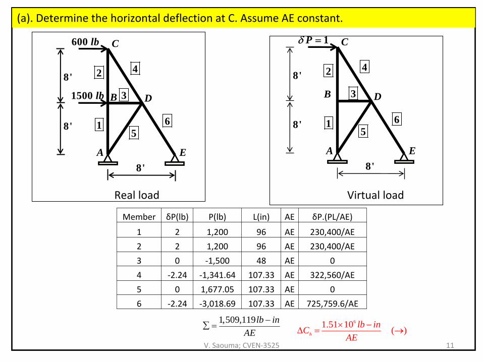
(a). Determine the horizontal deflection at C. Assume AE constant.
A E
D
C
B
600 lb
1500 lb
8'
8'
8'
2
15
6
4
3
A E
D
C
B
1Pδ =
8'
8'
8'
2
15
6
4
3
Real load Virtual load
Member δP(lb) P(lb) L(in) AE δP.(PL/AE)
1 2 1,200 96 AE 230,400/AE
2 2 1,200 96 AE 230,400/AE
3 0 ‐1,500 48 AE 0
4 ‐2.24 ‐1,341.64 107.33 AE 322,560/AE
5 0 1,677.05 107.33 AE 0
6 ‐2.24 ‐3,018.69 107.33 AE 725,759.6/AE
1,509,119lb inAE
−∑ = 61.51 10 ( )h
lb inCAE
× −Δ = →
V. Saouma; CVEN‐3525 12
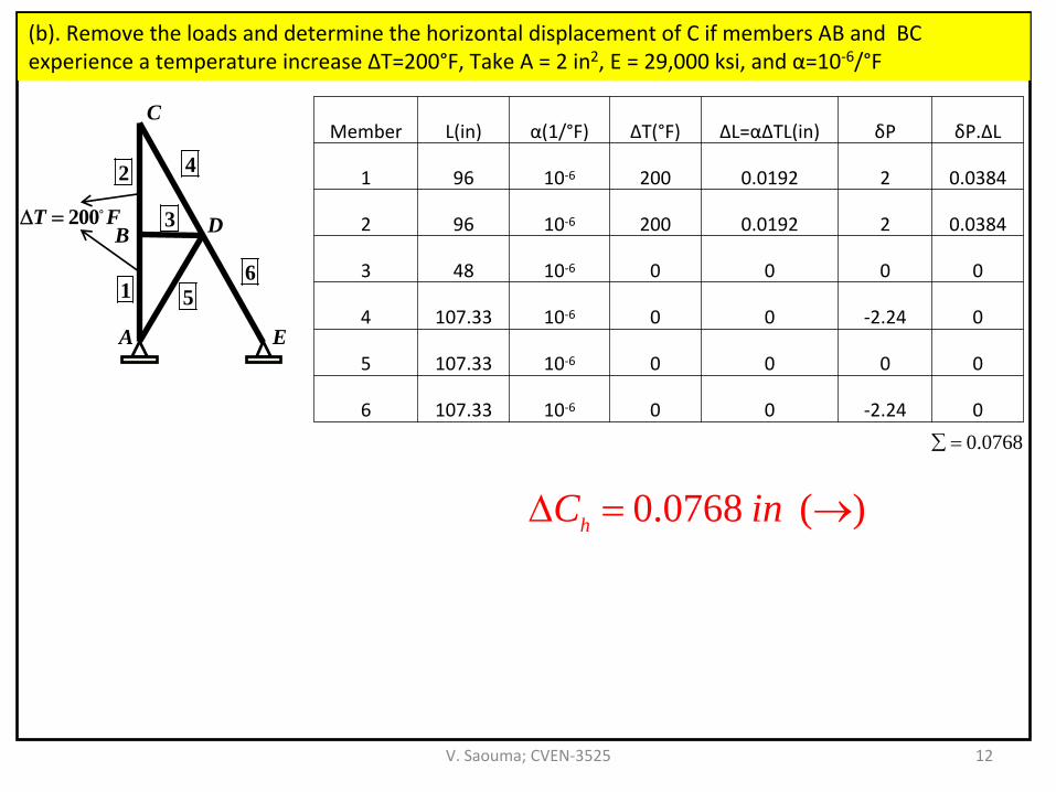
(b). Remove the loads and determine the horizontal displacement of C if members AB and BC
experience a temperature increase ΔТ=200°F, Take A = 2 in2, E = 29,000 ksi, and α=10‐6/°F
Member L(in) α(1/°F) ΔT(°F) ΔL=αΔTL(in) δP δP.ΔL
1 96 10‐6 200 0.0192 2 0.0384
2 96 10‐6 200 0.0192 2 0.0384
3 48 10‐6 0 0 0 0
4 107.33 10‐6 0 0 ‐2.24 0
5 107.33 10‐6 0 0 0 0
6 107.33 10‐6 0 0 ‐2.24 0
0.0768∑ =
0.0768 ( )hC inΔ = →
A E
D
C
B
2
1 56
4
3200T FΔ =
V. Saouma; CVEN‐3525 13
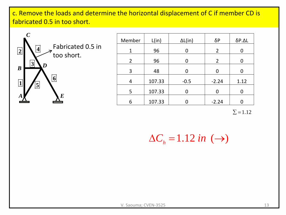
c. Remove the loads and determine the horizontal displacement of
C if member CD is
fabricated 0.5 in too short.
A E
D
C
B
2
1 56
4
3
Fabricated 0.5 in too short.
Member L(in) ΔL(in) δP δP.ΔL
1 96 0 2 0
2 96 0 2 0
3 48 0 0 0
4 107.33 ‐0.5 ‐2.24 1.12
5 107.33 0 0 0
6 107.33 0 ‐2.24 0
1.12∑ =
1.12 ( )hC inΔ = →