Embed Size (px)
Citation preview

FINAL DRAFT UGANDA
STANDARD
FDUS 947-1
First Edition2011-mm-dd
Reference numberFDUS 947-1: 2011
© UNBS 2011
Handling of petroleum products and their derivatives — Part 1: Siting, design and construction of service stations

FDUS 947-1: 2011
ii © UNBS 2011 – All rights reserved
Compliance with this standard does not, of itself confer immunity from legal obligations
A Uganda Standard does not purport to include all necessary provisions of a contract. Users are responsible for its correct application
© UNBS 2011
All rights reserved. Unless otherwise specified, no part of this publication may be reproduced or utilised in any form or by any means, electronic or mechanical, including photocopying and microfilm, without prior written permission from UNBS.
Requests for permission to reproduce this document should be addressed to
The Executive Director Uganda National Bureau of Standards P.O. Box 6329 Kampala Uganda Tel: 256 414 505 995 Fax: 256 414 286 123 E-mail: [email protected] Web: www.unbs.go.ug

FDUS 947-1:2011
© UNBS 2011 – All rights reserved iii
Contents Page
Foreword ............................................................................................................................................................ vi
1 Scope ...................................................................................................................................................... 1
2 Normative references ............................................................................................................................ 1
3 Terms and definitions ........................................................................................................................... 2
4 Planning of service station ................................................................................................................... 4 4.1 Service station siting ............................................................................................................................ 4 4.1.1 Environmental impact and fire hazard assessments ........................................................................ 4 4.1.2 Traffic impact assessment ................................................................................................................... 5 4.2 Composition ........................................................................................................................................... 5 4.3 Boundaries ............................................................................................................................................. 5 4.4 Design specifications for service stations ......................................................................................... 5 4.4.1 General ................................................................................................................................................... 5 4.4.2 Design area specifications ................................................................................................................... 6 4.5 Service station forecourt area classification ...................................................................................... 7 4.5.1 General ................................................................................................................................................... 7 4.5.2 Classified area examples ...................................................................................................................... 7 4.5.3 Protection of buildings with access to forecourts ............................................................................. 7 4.5.4 Fuels other than class 1 products ....................................................................................................... 8
5 Design and installation of underground tanks ................................................................................. 10 5.1 Tanks design installation and maintenance ..................................................................................... 10 5.1.1 Leakage detection ............................................................................................................................... 10 5.1.2 Steel tanks ............................................................................................................................................ 11 5.1.3 Fibre reinforced resin tanks ............................................................................................................... 11 5.1.4 Ultra violet protection ......................................................................................................................... 11 5.2 Site topography ................................................................................................................................... 11 5.2.1 General ................................................................................................................................................. 11 5.2.2 Excavations .......................................................................................................................................... 11 5.3 Corrosion protection ........................................................................................................................... 12 5.4 Transportation and offloading of steel tanks ................................................................................... 12 5.5 Transportation and offloading of fibre reinforced tanks ................................................................. 12 5.6 Back filling ........................................................................................................................................... 12 5.6.1 Stability ................................................................................................................................................. 12 5.6.2 Observation of wells ........................................................................................................................... 12 5.6.3 Backfill material ................................................................................................................................... 13 5.7 Installation of tanks and method of backfilling with cohesive backfill materials ......................... 13 5.7.1 General ................................................................................................................................................. 13 5.7.2 Water level ............................................................................................................................................ 13 5.7.3 Excavation of floor .............................................................................................................................. 13 5.7.4 Tank installation .................................................................................................................................. 14 5.7.5 Ballast fill .............................................................................................................................................. 14 5.7.6 Distribution of backfill ......................................................................................................................... 14 5.7.7 Other materials .................................................................................................................................... 14 5.8 Installation of tanks and methods of backfilling with cohesionless backfill material ................. 15 5.9 Holding down ....................................................................................................................................... 15 5.9.1 General ................................................................................................................................................. 15 5.9.2 Saddles ................................................................................................................................................. 15 5.10 Concrete slab ....................................................................................................................................... 15 5.11 Pipe connections and manholes on fibre-reinforced resin tanks .................................................. 16 5.11.1 Pipe connections ................................................................................................................................. 16 5.11.2 Manhole construction ......................................................................................................................... 16

FDUS 947-1: 2011
iv © UNBS 2011 – All rights reserved
5.11.3 Pipes .....................................................................................................................................................16 5.12 In-situ leak test .....................................................................................................................................16 5.13 Manufacturing and Installation ...........................................................................................................16
6 Pipe works and fittings .......................................................................................................................17 6.1 Steel pipe and fittings for welding .....................................................................................................17 6.1.1 General ..................................................................................................................................................17 6.1.2 Fittings ..................................................................................................................................................17 6.1.3 Flanges .................................................................................................................................................17 6.1.4 Gaskets .................................................................................................................................................17 6.2 Threaded steel pipe and fittings .........................................................................................................17 6.2.1 General ..................................................................................................................................................17 6.2.2 Fittings ..................................................................................................................................................17 6.2.3 Flanges .................................................................................................................................................17 6.2.4 Pipe threads .........................................................................................................................................17 6.3 Non-metallic piping..............................................................................................................................17 6.3.1 Material .................................................................................................................................................17 6.3.2 Fuel compatibility ................................................................................................................................18 6.3.3 Fuel permeability .................................................................................................................................18 6.3.4 Ultraviolet exposure ............................................................................................................................18 6.3.5 Primary delivery pipes ........................................................................................................................18 6.3.6 Vents .....................................................................................................................................................18 6.3.7 Fill pipes ...............................................................................................................................................18 6.3.8 Compressibility ....................................................................................................................................18 6.3.9 Transition ..............................................................................................................................................18 6.3.10 Shear-off valve .....................................................................................................................................18 6.4 Installation ............................................................................................................................................18 6.4.1 Pipework ...............................................................................................................................................18 6.4.2 Joint fittings .........................................................................................................................................19 6.4.3 Incline on pipe work ............................................................................................................................19 6.4.4 Jointing tape .........................................................................................................................................19 6.4.5 Buried pipe work ..................................................................................................................................19 6.4.6 Welding .................................................................................................................................................19 6.4.7 Pipework leak test................................................................................................................................19 6.4.8 Corrosion protection ...........................................................................................................................19 6.5 Dip pipes or gauging pipes .................................................................................................................19 6.6 Suction pipes .......................................................................................................................................19 6.7 Delivery pipes .......................................................................................................................................19 6.8 Breather pipes or vent pipes ..............................................................................................................20
7 Fillers, pumps and drainage ...............................................................................................................20 7.1 Fillers ....................................................................................................................................................20 7.1.1 General ..................................................................................................................................................20 7.1.2 Filler box ...............................................................................................................................................20 7.2 Pumps and dispensers .......................................................................................................................21 7.2.1 General ..................................................................................................................................................21 7.2.2 Dispensers and dispensing pumps ...................................................................................................21 7.2.3 Specific requirements .........................................................................................................................21 7.3 Drainage and interceptors ..................................................................................................................22 7.3.1 Surface water .......................................................................................................................................22 7.3.2 Containment separation ......................................................................................................................23 7.3.3 Sewage ..................................................................................................................................................23 7.3.4 Washing of vehicles ............................................................................................................................23 7.4 Overfill protection ................................................................................................................................24
8 Electrical installation ...........................................................................................................................24 8.1 General ..................................................................................................................................................24 8.2 Electric cables ......................................................................................................................................25 8.3 Buried cables .......................................................................................................................................25 8.4 Sleeve pipes .........................................................................................................................................25 8.5 Non-explosion-protected equipment .................................................................................................25

FDUS 947-1:2011
© UNBS 2011 – All rights reserved v
8.6 Accredited electricians and certification of electrical work ........................................................... 25 8.6.1 Electricians .......................................................................................................................................... 25 8.6.2 Electrical installations......................................................................................................................... 25 8.6.3 Certification .......................................................................................................................................... 25 8.7 Emergency ........................................................................................................................................... 25 8.8 Hazardous installations ...................................................................................................................... 25 9 Operation and maintenance of filling stations ................................................................................. 26 9.1 Marking of equipment ......................................................................................................................... 26 9.2 Notice and labels ................................................................................................................................. 26 9.3 Fire-fighting equipment ...................................................................................................................... 26 9.3.1 Portable and mobile fire extinguishers ............................................................................................. 26 9.3.2 Fire hoses ............................................................................................................................................. 26 9.3.3 Couplings ............................................................................................................................................. 26 9.3.4 Fire alarms............................................................................................................................................ 27 9.3.5 Colour identification of fire-fighting equipment ............................................................................... 27 9.3.6 Employees for fire-fighting ................................................................................................................. 27 9.4 Protection and welfare of personnel ................................................................................................. 27 9.4.1 Safety and protection measures ........................................................................................................ 27 9.4.2 Contact with petroleum products ...................................................................................................... 28 9.5 Repairs and alterations ....................................................................................................................... 28 9.5.1 Permits ................................................................................................................................................. 28 9.5.2 Equipment ............................................................................................................................................ 28 9.5.3 Pipelines, pumps and valves .............................................................................................................. 29 9.5.4 Hot work ............................................................................................................................................... 29 9.5.5 Electrical equipment............................................................................................................................ 29 9.5.6 Plant ...................................................................................................................................................... 29 9.6 Personnel safety .................................................................................................................................. 29 9.6.1 Supervision .......................................................................................................................................... 29 9.6.2 Use of casual and contractors' labour ............................................................................................... 29 9.7 Removal or abandonment of tanks and pipe work .......................................................................... 29 9.7.1 Removal ................................................................................................................................................ 29 9.7.2 Abandonment ...................................................................................................................................... 30 9.8 Registration .......................................................................................................................................... 32
Annex A (normative) Design and construction of tanks ............................................................................. 33 A.1 General ................................................................................................................................................. 33 A.2 Interceptors and drainage .................................................................................................................. 33 A.3 Used oil and solvent washings (paraffins) ....................................................................................... 34
Annex B (normative) PUR foam-forming systems and foams for filling abandoned tanks and pipework — Test methods .................................................................................................................. 35
B.1 Tests for foam-forming systems ........................................................................................................ 35 B.1.1 Determination of viscosity at (25 ± 1) °C of the components (isocyanate and polyol) of a
foam-forming system .......................................................................................................................... 35 B.1.2 Determination of foaming characteristics at (25 ± 1) °C: cream time, string time and rise
time ....................................................................................................................................................... 35 B.2 Determination of foam properties ...................................................................................................... 36 B.2.1 Foam samples ...................................................................................................................................... 36 B.2.2 Density of foam .................................................................................................................................... 36 B.2.3 Closed-cell content ............................................................................................................................. 36 B.2.4 Compressive strength......................................................................................................................... 37
Annex C (normative) Design criteria for interceptors (gravity separators) ............................................... 38 C.1 General ................................................................................................................................................. 38 C.2 Design procedure ................................................................................................................................ 38 C.3 Example ................................................................................................................................................ 39
Bibliography ...................................................................................................................................................... 42

FDUS 947-1: 2011
vi © UNBS 2011 – All rights reserved
Foreword
Uganda National Bureau of Standards (UNBS) is a parastatal under the Ministry of Tourism, Trade and Industry established under Cap 327, of the Laws of Uganda. UNBS is mandated to co-ordinate the elaboration of standards and is (a) a member of International Organisation for Standardisation (ISO) and
(b) a contact point for the WHO/FAO Codex Alimentarius Commission on Food Standards, and
(c) the National Enquiry Point on TBT/SPS Agreements of the World Trade Organisation (WTO).
The work of preparing Uganda Standards is carried out through Technical Committees. A Technical Committee is established to deliberate on standards in a given field or area and consists of representatives of consumers, traders, academicians, manufacturers, government and other stakeholders.
Draft Uganda Standards adopted by the Technical Committee are widely circulated to stakeholders and the general public for comments. The committee reviews the comments before recommending the draft standards for approval and declaration as Uganda Standards by the National Standards Council.
Committee membership
The following organisations were represented on the Technical Committee for Petroleum Standards, UNBS/TC 16/SC 2, during the development of this standard:
• Delta (U) Ltd
• Kampala City Council
• Kobil (U) Ltd
• Kyambogo University
• Makerere University
• Ministry of Energy and Mineral Development
• Ministry of Gender Labour and Social Development
• Ministry of Works and Transport
• National Council of Science and Technology
• National Environment Management Authority
• Total (U) Ltd
• Uganda National Bureau of Standards

FINAL DRAFT UGANDA STANDARD FDUS 947-1: 2011
© UNBS 2011 – All rights reserved 1
Handling of petroleum products and their derivatives — Part 1: Siting, design and construction of service stations
1 Scope
1.1 This Final Draft Standard covers the siting, design and construction of service stations, installation and operation of equipment in service stations for handling, storage and dispensing of petroleum products and their derivatives, other than equipments used in transportation.
1.2 A design will meet the requirement of this standard if it complies with any of the approved standards listed in normative reference. However, such standard will be used in it’s entirety where applicable. For example, the product classification of one standard cannot be used in combination with design of another standard.
1.3 This standard does not cover the installation of pressurized storage tanks such as liquefied petroleum gas (LPG) storage vessels.
2 Normative references
The following referenced documents are indispensable for the application of this document. For dated references, only the edition cited applies. For undated references, the latest edition of the referenced document (including any amendments) applies.
FDUS ISO 844, Cellular plastics — Determination of compression properties
FDUS ISO 1209-1, Determination of flexural properties — Part 1: Basic bending test
FDUS ISO 1209-2, Determination of creep behaviour — Part 2: Flexural creep by three-point loading
FDUS ISO 3219, Plastics — Polymers/resins in the liquid state or as emulsions or dispersions — Determination of viscosity using a rotational viscometer with defined shear rate
FDUS ISO 4590, Cellular plastics — Determination of volume percentage of open and closed cells of rigid materials
FDUS ISO 845, Cellular plastics and rubbers — Determination of apparent density
FDUS ISO 7-1, Pipe threads where pressure-tight joints are made on the threads — Part 1: Designation, dimensions and tolerances
DUS 974(API RP 1604), Closure of underground petroleum storage tanks.
US 159, Specification for steel pipes for water and gas suitable for screwing
FDUS 951-1:2011, Glass-reinforced polyester-coated steel tanks for the underground storage of hydrocarbons and oxygenated solvents and intended for burial horizontally
DUS 951-2:2011, Fibre-reinforced plastics (FRP) tanks for buried (underground) storage of petroleum product
2 © UNBS 2011 – All rights reserved
DUS 947-2, The storage and handling of liquid fuel – Part 2: Larger consumer installations
DUS 956, Steel pipe flanges.
DUS 975, The electrical components of free-standing power-operated dispensing devices for flammable liquids.
DUS 962 Symbolic safety signs – Part 1: Standard signs and general requirements.
DUS 955-2, Welding – Part 3: The fusion welding of steel (including stainless steel): Tests for the approval of welding procedures and production welds
DUS 963, Cathodic protection of buried and submerged structures.
DUS 961, Welded steel tanks for oil storage
DUS 960, The wiring of premises.
DUS 976, Identification colour marking – Part 1: General.
US ISO 7165:2009 Fire fighting — Portable fire extinguishers — Performance and construction
US 534, Occupational health and safety management systems — Specification The application of the National Building Regulations
3 Terms and definitions
For the purposes of this standard, the following terms and definitions shall apply.
3.1 acceptable: acceptable to the parties concluding the purchase contract, but in relation to the certification mark and to inspections carried out by approving authority, acceptable to the Uganda National Bureau of Standards
3.2 approved: accepted by the appropriate approving authority
3.3 approving authority: appropriate of the following:
a) in terms of the Occupational Health and Safety Act 2006, the Commissioner Occupational health and Safety Act, Ministry of Gender Labour and Social Development;
b) in terms of petroleum supply act 2003, the Commissioner Petroleum Supply Department, Ministry of Energy and Mineral Development;
c) in terms of the Uganda National Bureau of Standards Act 1993, The Executive Director Uganda National Bureau of Standards;
d) in terms of Weights and Measures Act 1993 Cap 93, The Executive Director Uganda National Bureau of Standards;
e) in terms of the Environmental Act 1995,The Executive Director National Environmental Management Authority; and
f) the local authorities concerned.
FDUS : 2011
© UNBS 2011 – All rights reserved 3
947-1
3.4 backfill material: clean, sieved subsoil or sand of specified grading
3.5 competent person: person who has the necessary knowledge of and ability with regard to the particular process or type of plant and equipment to which this standard refers, to render him capable of the work involved, and who has been duly authorized (in writing) by the approving authority to perform a specific and identified task
3.6 dispenser: unit that consists of one or more meters and one or more hoses and that is fed from a remote pump.
3.7 dispensing pump: unit that consists of one or more meters and one or more hoses and that has its own pump(s) within the unit
3.8 responsible engineer: engineer who is registered under Engineer registration act (1969) of Uganda as amended under decree no. 10 of 1977
3.9 fibre-reinforced resin steel tank: steel tank that has a fibre-reinforced resin coating on the outside of the tank
3.10 fibre-reinforced resin tank: tank made from a number of fibre glass strands (reinforcement) bound together using a resin and catalyst
3.11 filler: point for filling the tank with product
3.12 filler box: box surrounding the filler point
3.13 flash point: temperature at which a liquid ignites
3.14 holiday test defect: lining or coating defect where the coating is so thin or the coating material has been so degraded or so contaminated that the defect is registered by a suitable holiday detector (correctly used and set at an appropriate voltage) and that the protective properties of the lining or coating are impaired
3.15 oxygenates: generic term for products such as methanol, ethanol, isopropanol, tertiary, butyl alcohol, tertiary methyl butyl ether and tertiary amyl methyl ether
3.16 rapid drainage system: system that allows drainage of spillage from the filler box to the relevant underground tank and that is controlled by a suitable valve

4 © UNBS 2011 – All rights reserved
3.17 submersible pump: remote pump that feeds one or more dispensers and that is either completely submersed in the product or has its rotating parts submersed in the product within a tank
3.18 service station: facility constructed under this standard that offers sufficient capabilities to handle the storage of petroleum products (fuels and lubricants) in underground tanks, of individual tank capacity not exceeding 85 m3 and offering total storage capacity not exceeding 200 m3, and dispensing them to final consumers
3.19 filling station facility constructed under this standard that offers sufficient capabilities to handle the storage of automotive fuels within underground tanks of individual capacity not exceeding 85 m3 and total facility capacity not exceeding 200 m3 and dispensing it to final consumers units
3.20 forecourt open area in a service/filling station where automobiles stop to refuel
3.21 tank farm area where one or more petroleum products tanks are sited
4 Planning of service station
4.1 Service station siting
4.1.1 Environmental impact and fire hazard assessments
Hydrocarbons are volatile under certain conditions and contain or can easily form harmful chemical compounds, making them prone to environmental destruction and fire hazards. The siting of service stations is therefore paramount not only in facilitating marketing but is also vital in the aspects of protection from fire hazards, destruction of environment and disruption to other operations. Awareness to the approving authority on the following shall therefore be made by submission of environmental impact assessment, before construction of service station begins:
a) location of site in respect to other existing or planned developments, water bodies, areas of fragile ecosystem and other risk areas that could be exposed in the event of accidental spillage;
b) access to various facilities within the service station for effective and efficient operation and maintenance;
c) fall of ground in respect to various sources of ignition and other risky operations, that may render the facility insecure;
d) drainage system especially how it links up with the drainage system of the Local Authority;
e) location of existing boreholes, aquifers or artesian wells with 500 m where an analysis of hydrogen sulphide and hydrocarbon will periodically be done; and
f) soil types and the depth down to the first impermeable layer.

FDUS : 2011
© UNBS 2011 – All rights reserved 5
947-1
4.1.2 Traffic impact assessment
A service station is a major generator of road traffic congestion and as such presents a high degree of traffic on the road section onto which it is sited. This determines the number of stations that can be permitted on any section of the road or high way in any section of the city. The objective is to keep traffic to minimum and therefore, the following shall be observed in siting service stations:
a) service stations shall be sited at distance of not less than 1000 m from each other on the same section of the single carriage road, this applies to either side of the dual carriage road;
b) a service station shall not be located opposite a break or opening in the central verge of dual carriage;
c) a filling station shall not be sited too close to an intersection to a traffic island on the main road. The minimum distance between an access to a service station and the tangent of a traffic island shall be 80 m;
d) no siting of stations shall be allowed on road curves and bends and shall not be located adjacent to residential houses; and
e) the minimum distance of a property line (Service station) from the centre line of the single carriage road must not be less than 15 m.
4.2 Composition
The service station shall compose of such structures, equipment and installations designed and constructed in such a way as to make the facility efficient in handling the storage and dispensing of petroleum products, with no damage to the environment and able to offer safety and hygiene to personnel. A service station layout shall therefore be composed of but not limited to the following structures:
• forecourt,
• tank farm,
• buildings, and
• entrances and exits
4.3 Boundaries
In respect to the surroundings environment, appropriate boundary fencing shall be provided for the interest of security of the station and the surrounding environment. For a service station in an urban setting, an appropriate wall fence in brick/blockwork bonded by cement–sand mortar) raised at least 1.8 m high shall be erected around the station excluding the frontage, all subject to the local authorities approval.
4.4 Design specifications for service stations
4.4.1 General
Plans submitted for approval to the approving authority shall be endorsed by a responsible engineer who hereby certifies that such plans comply with the provisions of this standard and other relevant government laws or regulatory measures existing at the time.

6 © UNBS 2011 – All rights reserved
4.4.2 Design area specifications
4.4.2.1 Total service station coverage area
The total area required will depend on forecourt area, the size and orientation of the building and, tank farm area (depending on number and capacity of installed underground tanks). To allow for turning of vehicles and to avoid traffic congestion within the station area, the minimum area of a service station shall be set as follows.
a) the minimum size for a filling station shall be 30 m x 30 m; however, in intensely developed areas the frontage can be relaxed after investigation subject to approval of the relevant authority(ies). This area excludes area required for other services other than storage and dispensing petroleum products (motor fuel); and
b) the minimum size for a service station (filling station with a service bay) shall be 1 200 m2, with the frontage of not less than 30 m;
c) every service station shall provide for one parking space for each of its four employees with a minimum of two-car parking space and, where additional service(s) exist, the parking space shall be enough to accommodate the additional vehicles as required by the national building regulations.
4.4.2.2 Forecourt specification
The service station forecourt shall be a non-slippery surface structure, constructed of materials that are impermeable to, and cannot react with petroleum products. Preferred materials are but not limited to concrete
The minimum area of service station forecourt will depend on number of pumps dispenser or dispenser islands. Dispenser islands in a forecourt shall be designed and laid in such a way to provide a driveway of not less than 6 m on either side. Consequently, adjacent dispenser islands shall be separated from each other by 6 m.
The hazardous area around the dispenser islands shall be covered with a canopy extending outside a minimum of 1.5 m on all sides and raised as to comply with building regulations.
The slope of the forecourt shall be maintained between 1:50 and a maximum 1:20 in hilly places, fixed in such a way that effluent flows to appropriate channels and not to the road.
4.4.2.3 Tank farm specification
The area where underground tanks are installed shall be clearly separated from the forecourt, well protected and maintained. In intensely developed areas, tank farms can be integrated within the forecourt subject to approval of approving authority after ensuring that sufficient structures have been included in the design to prevent the deformation of tanks by various loads.
The tank farm area will depend on the number and size of installed underground tanks estimated as per specifications in 5.2.2.2.
4.4.2.4 Buildings specifications
Each service station shall include buildings, constructed in conformity with building and construction standards and regulations existing at the time, to serve but not limited to functions of office block, sanitary wash rooms, canopy, generator house and service station store.
Buildings shall be constructed of inflammable materials and their wiring systems shall conform to Ministry of Works and Transport; Electrical Installations and Equipment in Buildings Regulation 2004.

FDUS : 2011
© UNBS 2011 – All rights reserved 7
947-1
4.4.2.5 Exits and entrances
The entrances and exits to the service station shall be of sufficient size and be positioned in such a way that drivers are not obstructed from other road users by structures and features within and in the neighbourhood. In detail, the following shall be considered:
a) minimum width of the entrance and exits including the side walk shall be 9.0 m;
b) maximum angle of intersection of the drive way with the street pavement shall be 45 °;
c) minimum distance of the driveway to any exterior property line shall be 6 m; and
d) minimum distance between kerbs sites shall be 9 m ( width of entrances).
4.5 Service station forecourt area classification
4.5.1 General
The equipment of the forecourt under normal open area conditions shall comply with the requirements in 4.5.2 to 4.5.4.
4.5.2 Classified area examples
The direct classification examples for typical service station conditions are given in figures 1 to 5. These classification examples shall also be applied to non-retail dispensing sites. The Zone 2 areas indicated cover the possibility of localized hazardous areas being present for short periods, with such areas being well ventilated under open area conditions.
The classified areas indicated relate to the installation of fixed electrical equipment and shall not be considered as extending beyond an unpierced wall, roof or other vapour barrier or solid partition.
4.5.3 Protection of buildings with access to forecourts
Kiosks, sales rooms, storage rooms, restrooms and other buildings with openings to a hazard zone shall be classified according to that zone at the same height throughout the building. Such buildings shall be well ventilated and heating apparatus shall be positioned in such a way that it is not possible to have a source of ignition in a hazardous area during normal operations or in the event of an outside spillage.
Fixed heating shall only be of the type where the surface temperature does not exceed 100 °C and all staff shall be warned against introducing any other type of portable appliance.
Wherever possible, kiosks or other types of buildings shall not be within any hazardous area. Further care shall be taken not to introduce sources of ignition into hazardous locations, for example, cold drink dispensers and fridges, electrical signage, sound systems or uncertified portable credit card readers.

8 © UNBS 2011 – All rights reserved
Figure 1 — Underground tank with class I flammable liquids or class II and III combustible liquids at temperatures at or above their flash points, with gravity filling
4.5.4 Fuels other than class 1 products
The requirements in 4.5.2 to 4.5.3 apply to the handling of class I products, for example, petrol type fuels. It shall be noted that this standard does not distinguish in its design and constructional features between dispensing units for class I (PMS) and class II (AGO and BIK) products. Such class II products do not cause a hazardous area outside dispensers, but the inside area classification remains the same.
Figure 2 — Underground tank with class II and III combustible liquids at temperatures below their flash points, with gravity filling

FDUS : 2011
© UNBS 2011 – All rights reserved 9
947-1
Figure 3 — Low hose dispenser with vapour barrier
Figure 4 — High hose metering pump/dispenser — without sight glass and with vapour barrier

10 © UNBS 2011 – All rights reserved
Figure 5 — Workshop with pit
Construction and installation of underground tanks, pipe works, pump dispensers and electrical installation and other equipment are covered in details in next sections
5 Design and installation of underground tanks
5.1 Tanks design installation and maintenance
Tanks shall be situated at suitable distances from buildings, roadways or other structures as to comply with the relevant provisions of building and civil engineering regulations (this is covered in DUS- 947-2 and national construction and building regulations)
5.1.1 Leakage detection
5.1.1.1 Fuel leakage detection
Tanks of Individual capacity exceeding 30 m3 shall be fitted with an appropriate leakage detection facility corresponding to either of the following forms or employing appropriate technology subjected to approval of the approving authority.
a) Electrical — A water/hydrocarbon sensitive probe positioned in the base of the tank at the time of manufacture. This probe sets on an alarm shall it detect product out of the primary tank, or water into the secondary tank.
b) Mechanical — A 50 mm diameter drop tube installed at the time of manufacture, running from the top to the bottom of the tank and into the interstitial space. A float switch fixed to the inside of the tube can trigger a warning light and indicate product or water into the interstitial space.
c) Vacuum test — A negative 35 kPa vacuum test, held for 30 min, is used to detect a leak in the interstitial space.
d) Volume change — The interstitial space is filled with a fluid such as tri-ethylene glycol (steel tanks) or brine (fiber-glass tanks) at the time of manufacture. A leak in either the inner or the outer skin causes a volume change detected by a level indicator located at the top of the tank
FDUS : 2011
© UNBS 2011 – All rights reserved 11
947-1
5.1.1.2 Water detection
Water may enter the primary tank from loose tank top fittings. Water shall be detected by periodically wiping water-finding paste onto the bottom of the tank dipstick where a change of colour indicating the depth of water present or by an appropriate technology subject to approval.
Some more sophisticated double wall tanks may be fitted with an electronic sensor in the interstitial space to detect the presence of water.
5.1.2 Steel tanks
Steel tanks and fibre reinforced steel tanks shall comply with requirement of DUS 951-2.
5.1.3 Fibre reinforced resin tanks
These shall comply with the requirement of standard FDUS 951-1, and all materials used in contact with the tank shall be compatible with fibre reinforced resin.
5.1.4 Ultra violet protection
While on site before installation fibre reinforced tanks shall be protected against ultra violet radiations by acceptable means.
5.2 Site topography
5.2.1 General
Each contractor or installer shall be in possession of an approved plan before excavation of the site starts (see building regulations) fully approved by the inspection authority and marking of the plan shall be evident
NOTE This is not a requirement for general maintenance and emergency works to existing service stations for which no major modification has been done
5.2.2 Excavations
5.2.2.1 All the excavation shall be carried out in approved manner to comply with the requirement of Occupational Health and Safety Act 2006 as well as the required specification in building and civil engineering standards
5.2.2.2 The depth of excavation measured downwards from the proposed finished ground level or from the top of the finished drive way surface shall be at least equal to the sum of tank diameter and,
a) at least 150 mm for the depth of the bedding layer plus
b) at least 750 mm for the depth of the overlay.
The width and length shall be in accordance with the tank plan dimensions plus the clearance of at least 500 mm all around.
5.2.2.3 The difference between tanks in a single excavation shall be at least 500mm
5.2.2.4 The contactor or installer shall use suitable equipment to keep the exaction free of visible water during construction period. No part of excavation shall intersect a line projected at downwards at 450 from the outer edge of the structural foundation, unless the exaction is approved by and under the strict control of a suitably qualified and recognized engineer.

12 © UNBS 2011 – All rights reserved
5.3 Corrosion protection
When cathodic protection of the tanks and pipe works is needed, it shall be provided in accordance with DUS 963 Where cathodic protection is installed within hazardous location, the safety parameter laid down in DUS 965 shall be strictly adhered to.
5.4 Transportation and offloading of steel tanks
5.4.1 The manufacturer or supplier shall not permit loading or transport of the tank unless suitable equipment is available and used
5.4.2 During transportation, the tanks shall rest of sand bags or any other suitable padding and shall be held down with webbing strops and not with wire chains or wire cables.
5.4.3 All tanks shall be fitted with the lifting rigs, to enable lifting straps and shackles to be used and if the spread angle exceeds 600 at the apex, a spreader bar shall be used. All lifting equipments shall comply with the regulations and procedures of the Occupational and Health Safety Act.
5.4.4 When a tank is offloaded, it shall be lifted clear off the transport courage and lowered either directly to the exaction pit or onto saddles, old tyres or other acceptable supporting materials of sufficient surface area to prevent damage to the coating of the tank.
5.4.5 The tank shall be lowered gently into the exaction. Rolling of the tank shall not permitted at a time during transport, offloading and installation
5.5 Transportation and offloading of fibre reinforced tanks
5.5.1 During transportation the tank shall rest on sand bags or other suitable padding and shall be held down with webbing strops and not with chains or wire cables.
5.5.2 During offloading, the tanks shall be prevented from rolling over or dropping. Chains or wire cable shall not be used in handling of tanks unless in conjunction with the lifting lugs. Chain or cable shall not be used around fibre reinforced tanks or fibre-lined tanks.
5.6 Back filling
5.6.1 Stability
The stability of underground tanks depends on backfill support, and is therefore essential that the correct backfill be used. The backfiller shall be spread in layers of 150mm each layer being compacted to the requirement of standard Ministry of Works and Transport Building Control Regulation amended August 2010 Underground tanks are designed to be used with adequate backfill support, and they shall be installed using acceptable construction practices and acceptable fill materials. Improper installation can cause tank damage.
5.6.2 Observation of wells
An engineering professional may do a risk assessment at each new site to determine if future observation wells are necessary.
If no risk assessment is done, observation wells (two for a single tank and four for a multi tank installation) shall be installed in the following manner before backfilling takes place:
a) a non-metallic sloted/perfolated pipe of internal diameter of at least 100 mm, wrapped in a porous geotextile, or
b) acrylonnitrile-butadiene-styrene(ABS) single walled wedge-slot tubular screens,

FDUS : 2011
© UNBS 2011 – All rights reserved 13
947-1
shall be placed in each corner of excavation. The bottom ends shall be plugged and top end finished off with a suitable cover.
NOTE Non metallic piping for this observation should be rigid enough to withstand the compaction loads.
If the soil at the bottom of excavation is of sandy nature the observation well shall be taken 500 mm below the floor of excavation
5.6.3 Backfill material
The method to be adopted for backfilling of excavations for all types of underground tanks shall depend on the type of backfill used, as well as on the approval of the site engineer for the type of back fill material to be used. One of the following materials shall be used as backfill:
a) sand: clean, inert, granular, well graded sand, free from any organic matter material, and of grading 0.02 mm to 2 mm. Appropriate sand includes
• plaster sand,
• building sand, and
• river sand
b) stone crushing: Clean and free-flowing crusher dust, obtainable from commercial sources and that complies with the following requirements:
• 100 % passing a 19 mm sieve;
• 98 % passing a 13.2 mm sieve;
• 90 % passing a 4.75 mm sieve;
• not more than 20 % passing a 75 μm sieve; and
• maximum pH of 6.0.
c) gravel: clean and free flowing naturally rounded cohesionless gravel of nominal diameter 6mm and particle size diameter in the range 3mm to 10mm. A washed river sand would also fall under this classification
Clay, silts, slags and cinders shall never be used
5.7 Installation of tanks and method of backfilling with cohesive backfill materials
5.7.1 General
Holiday test of 35 000 V, certified by the owner of the equipment shall be carried out on the tank before instalment.
5.7.2 Water level
The water level shall be maintained lower than excavation by de-watering from a sump.
5.7.3 Excavation of floor
To ensure that the bottom of the hole is flat, level and free from rocks and other foreign objects, and that the highest point of excavation is covered with at least 150 mm of backfill material compacted to the specification

14 © UNBS 2011 – All rights reserved
of engineering professional. If so required by the purchaser’s engineer and as added precaution against products leaks (in pipes or tanks), a suitable non-metallic sheet (see Figure 6) shall be placed on a bed of a river sand of thickness at least 150 mm. the sheeting shall be so placed that it has a fall of at least 150 mm to one corner in which an observation well shall be installed.
5.7.4 Tank installation
Place the tank into excavation (in their correct position) and level them to ensure that the fitting apertures are in their correct positions. Install the necessary fittings and check to ensure that they are vertical.
Figure 6 — Cross section through underground tank
5.7.5 Ballast fill
Ballast fill the tanks with sufficient water (or product as previously agreed upon and subject to the approval of local authority) to steady the tank and hold it in position.
NOTE 1 While holding the ballast, use the lifting lug (or webbing strop, as relevant) to keep the tank in position.
NOTE 2 Ballast is not necessary in a dry excavation
5.7.6 Distribution of backfill
Distribute the backfill material evenly around the tank(s) in uniform horizontal layers, ensuring that no part of backfill is more than 300 mm above any other part. The layers shall have a compacted thickness of 150 mm and the backfill shall be compacted to a suitable compacted level as indicated on the approved plan.
5.7.7 Other materials
Shall the construction programme warrant it, the backfill indicated on the plan may be stabilized with Ordinary Portland Cement.

FDUS : 2011
© UNBS 2011 – All rights reserved 15
947-1
5.8 Installation of tanks and methods of backfilling with cohesionless backfill material
Cohesionless back fill material is regarded as free-flowing and can be poured into the excavation, ensuring that no part of backfill is more than 300mm above any other part at any given time. The installation procedures shall include the following:
a) maintain the water table below that of the excavation by de watering from a sump;
b) spread a layer of back fill of thickness of at least 150 mm evenly at the bottom of the excavation;
c) lower the tank into excavation, position and level them;
d) fill the tank as in 5.7.5; and
e) backfill in accordance as 5.7.7. No stabilization with cement is deemed necessary when using this type of backfill, but water can assist in consolidation of this type of material.
The backfilling around fibre-reinforced resin tanks shall be cohesionless gravel (pea gravel)
5.9 Holding down
5.9.1 General
When local conditions dictate the likelihood of the water table rising above the level of installed tank, precautions shall be taken to counter the buoyancy force on the tank by installing either saddles and concrete slab or a single suitable concrete slab.
5.9.2 Saddles
If the concrete slab is so constructed at ground level that load is transferred to the tank via the soil, there can be sufficient mass in the slab itself and thus concrete saddles must be installed directly on top of the tank shell. Saddles transmit the load of the slab to the tank shell as a concentrated load, and cognizance shall be taken of the fact when the tank is being designed.
It is recommended that saddles are placed a length equating to one quarter of the tank diameter from the tank ends, but placing shall be as indicated on the plan.
If a reinforced concrete slab is to be used to hold the tank down, a leak test shall be carried out on the tank preferably before the slab is cast, in case the tank has to be removed for repairs.
The concrete slab can be constructed directly on top of the tank shell(separated by melthoid or equivalent material) to take advantage of the mass of superimposed soil and permit access to pipe runs without having to break up the concrete.
5.10 Concrete slab
A concrete slab shall be so designed that
a) its length and with exceed the length and width of the tank(s) by at least 600 mm on all sides
b) its thickness is at least 150 mm, but may be increased if so specified by the purchaser, and
c) the top and bottom reinforcement consist of mild steel bars of diameter at least 6 mm, at centres of not more than 150 mm in both directions, and double gland type fitting for plain end pipe

16 © UNBS 2011 – All rights reserved
5.11 Pipe connections and manholes on fibre-reinforced resin tanks
5.11.1 Pipe connections
Piping shall be free to move with the tank. Connections into the tank shall be made with short lengths of acceptable flexible hose, using compression fittings, or double gland type fittings for plain end pipe.
5.11.2 Manhole construction
Do not place bricks or other manhole materials directly onto the tank surface. The tank shall be separated from the manhole itself by either backfilling material, melthoid or similar materials. Manholes may be constructed from but are not limited to the following materials: load-bearing brickwork (fully bedded and jointed), high density poly-ethylene, precast or in-situ concrete and fibre-reinforced resin. Manholes shall be of diameter at least 1 m and minimum length 1 m, and shall be so designed as to prevent the ingress of surface water.
5.11.3 Pipes
Piping for tanks other than fibre-reinforced resin tanks may be of steel black piping, protected against corrosion by a petrolatum gauze wrapping, together with a PVC outer wrap, or of a suitable non-metallic material. However, the pipe work on the upstream (tank) side of the dispensing delivery pump and the dispenser bottom connecting union, or of the shear coupler, shall be installed in accordance with the dispenser manufacturer's requirements.
When steel piping is used it shall be protected against corrosion by petrolatum gauze wrapping, together with a PVC outer wrap, with at least 50% overlaps. All steel piping shall comply with the requirements of US159 for medium pressure rating (for cathodic protection, see also 5.3).
5.12 In-situ leak test
A full system pressure leak test at 40 kPa in accordance with an approved test method shall be carried out on the tank after installation.
5.13 Manufacturing and Installation
The purchaser or his appointed agent shall be permitted to inspect the materials or the work of the tank manufacturer at any time
The installer shall provide the approving authority with a certificate stating that a competent person has
a) examined the excavation and witnessed the placing of the tank in the excavation,
b) witnessed an in-situ leak test being performed on the tank,
c) witnessed a leak test being performed on the pipework, and
d) witnessed a 35 000 V holiday test on the tank before it was placed into the excavation.

FDUS : 2011
© UNBS 2011 – All rights reserved 17
947-1
6 Pipe works and fittings
6.1 Steel pipe and fittings for welding
6.1.1 General
Piping for welding shall be suitable for working pressures of up to 1 000 kPa and shall comply with the requirements of at least US 159. The piping shall be plain end, bevelled for welding, electric-resistance welded, submerged arc welded or seamless.
6.1.2 Fittings
Fittings for welding shall comply with the requirements of an DUS 955-2.
6.1.3 Flanges
Flanges for welding shall be of class 150 pressure-temperature rating, slip-on or weld neck flanges that comply with the requirements of DUS 956.
6.1.4 Gaskets
Gaskets shall be non-asbestos, compatible with the liquid being handled, of thickness at least 1.5 mm and shall comply with an approved standard.
6.2 Threaded steel pipe and fittings
6.2.1 General
Threaded steel piping shall comply with the requirements of US 159. No galvanized pipes and fittings shall be used.
6.2.2 Fittings
Only threaded mild steel fittings shall be used. Unions shall be cone-faced.
6.2.3 Flanges
Threaded flanges shall be of steel, and shall comply with the requirements for class 150 pressure-temperature rating of DUS 956or another approved standard.
6.2.4 Pipe threads
Pipe threads shall comply with the requirements of ISO 7-1 or another approved standard.
6.3 Non-metallic piping
6.3.1 Material
All components of an installation shall be capable of operating in the prevailing soil conditions. If the material is susceptible to degradation from exposure to alkalis, acids, aqueous salts and hydrocarbons, acceptable adequate protection shall be applied.

18 © UNBS 2011 – All rights reserved
6.3.2 Fuel compatibility
No significant degradation of the properties of the material shall occur over the life of the installation. The various additives and blends in fuels shall be noted and considered.
6.3.3 Fuel permeability
Where non-metallic permeable materials are used for piping, the rate of permeation shall not exceed 2 g/m2.day at a temperature of 23 °C.
6.3.4 Ultraviolet exposure
All non-metallic components shall be able to withstand six months continual weathering before installation without significant property degradation.
6.3.5 Primary delivery pipes
Both positive pressure and vacuum suction lines where the pipes continually contain liquid fuel shall be capable of withstanding 4 bar positive pressure and a 10 bar peak pressure pulse.
Suction lines shall be capable of withstanding 0.6 bar vacuum and a 0.7 bar peak vacuum pulse, and a 1 bar positive pressure.
6.3.6 Vents
Vent lines that contain petroleum vapours but that are not normally exposed to liquid fuel shall be capable of withstanding 1 bar pressure and 0.1 bar vacuum pulse.
6.3.7 Fill pipes
Fill lines experience regular, but short periods of exposure to liquid fuels and continual exposure to petroleum vapours. The lines shall be capable of withstanding 1 bar positive pressure and a 0.6 bar vacuum pulse.
6.3.8 Compressibility
Pipes shall not deform more than 5 % when subjected to normal road wheel loads at a cover of 300 mm. Stabilized material or concrete may be used as backfill to reduce any deformation of the pipe.
6.3.9 Transition
When non-metallic piping is used, the transition from steel tank fittings to non-metallic fittings shall be made in the manhole nearest to the tank.
6.3.10 Shear-off valve
The vertical riser beneath any remote dispenser shall be so firmly fixed as to ensure the correct functioning of the shear-off valve of the dispenser and shall comply with the manufacturing requirements.
6.4 Installation
6.4.1 Pipework
Steel pipework shall be laid out in a geometrical pattern and shall be indicated on the plan of the site. All non-metallic piping shall be laid out in accordance with the manufacturer's recommendations.

FDUS : 2011
© UNBS 2011 – All rights reserved 19
947-1
6.4.2 Joint fittings
Only standard fittings shall be used on joints.
6.4.3 Incline on pipe work
Pipe work shall be designed by a competent person to have an adequate fall to the tank from the dispenser(s) or suction pump(s), vent(s) or breather(s), and fill point(s).
6.4.4 Jointing tape
Jointing tape or compound used on screwed threads shall be of an acceptable quality.
6.4.5 Buried pipe work
All buried pipe work shall be covered by backfill of thickness at least 300 mm. A shallower backfill may be permitted if it is of a reasonable engineering design.
6.4.6 Welding
All welds shall be visually inspected for compliance with DUS 955-2. All welding for non-metallic type piping (where applicable) shall comply with an approved standard.
6.4.7 Pipework leak test
Before the pipe work system is backfilled, it shall be isolated from the tank(s) and pump/dispenser and subjected to a pneumatic pressure of at least 600 kPa or to a nitrogen gas and soap solution test for at least 1 hour. A hydraulic test can be performed, with the pressure being maintained for 15 min at 1 000 kPa, or an ultrasonic leak detector can be used to search for leaks within the system.
6.4.8 Corrosion protection
All steel pipes and fittings shall be corrosion protected by means of wrapping. Cathodic protection of the pipe work may be the same as for the tank if so specified by the competent person in charge.
6.5 Dip pipes or gauging pipes
Each tank shall have a connection through which the contents of the tank can be manually or automatically gauged. The connection shall be of nominal diameter at least 40 mm and shall be fitted with a lockable cap capable of sealing against a hydrostatic pressure at least equal to the pressure of the tank or that of the delivery head (whichever is the greatest).
NOTE In order to avoid spillage in case of an overfill, this dip cap should be in the closed, sealed position whilst deliveries are taking place.
6.6 Suction pipes
Where suction pipes are installed to each pump, a non-return valve shall be fitted at the base of and under the pump and not in the manhole chamber.
6.7 Delivery pipes
Delivery pipes are installed where submersible pumps are used. A single header for each product or a designed header that is site specific shall be run along or underneath the line of the dispenser island(s).
NOTE For maintenance purposes an isolating valve may be fitted to the branches of the dispensers.

20 © UNBS 2011 – All rights reserved
6.8 Breather pipes or vent pipes
Breather pipes or vent pipes shall be of internal diameter at least 50 mm and shall terminate at a distance of at least 1.5 m away from any opening to a building, the distance being measured horizontally. The vent pipes shall so terminate that the fumes are exhausted vertically upwards or horizontally. Discharge shall not be vertically downwards. The termination shall be protected by means of a screen.
The fact that petroleum vapours are heavier than air shall be taken into account, and free rapid dispersion shall be allowed for at the termination of the vent. No brick or other architectural screening of the vent termination shall be permitted. One vent per tank is required and these shall not be manifolded since overfills can lead to cross-contamination. The vent outlets shall be so located that they
a) are not situated beyond the existing building line boundary on a stand excluding the street boundary,
b) allow unrestricted venting to the open air,
c) are at least
i. 600 mm above roof level,
ii. 3.5 m above ground level,
iii. 1.5 m from any door, window, or other opening in a building, and
iv. 3 m from any chimney opening, any hot surface, or any source of ignition,
d) are, if possible, within sight of the filling point (under certain circumstances, where the vent outlet is not within sight of the filling point, the approving authority may require that an alternative warning system/procedure be employed to guard against the possibility of overfilling), and
e) are not installed within 1.5 m of any electrical and electronic equipment.
All breather/vent pipes shall be cross bonded using 25 mm copper cable and connected to a copper earth spike of length at least 1.2 m and of diameter 10 mm, driven into the ground as near as possible to the pipe(s) and connected to the pipe(s) using 25 mm green-plastic-insulated copper conductor. This copper conductor shall then be connected to the earth continuity of the site by an acceptable means, for example with a copper U-bolt.
7 Fillers, pumps and drainage
7.1 Fillers
7.1.1 General
Underground tanks shall be filled by gravity filling. No direct connection pump deliveries shall be permitted unless there is an engineered system/adaptor fitted which will prevent excess pressure being placed on the tank.
Fillers shall be so sited that surface water and soil are prevented from entering the filler box. Each of the fillers shall be so sited that the tanker is able to leave the premises without having to reverse, and can park safely when bulk deliveries are being made. Where limited access prevents tankers from parking or entering the premises, filler sites shall be designed by the engineering professional to accommodate them.
7.1.2 Filler box
The filler box shall be leak proof, shall be able to contain the contents of a bulk delivery vehicle discharge hose, and shall be of capacity not less than 35 R.

FDUS : 2011
© UNBS 2011 – All rights reserved 21
947-1
7.1.2.1 Metal filler box
Each metal filler box shall have a frame bolt that can be used as an earth connection point, and the filler box shall be connected to the electrical earth continuity conductor of the installation. A metal tag shall be provided onto which the operator can connect the bonding cable from the bulk vehicle while delivering product.
7.1.2.2 Non-conductive filler boxes
In a non-conductive filler box, the conductive parts inside the box shall be connected to the electrical earth continuity conductor, and a connection point shall be provided onto which the operator can connect the bonding cable of the bulk vehicle.
7.2 Pumps and dispensers
7.2.1 General
Submersible pumps, dispensers and suction pumps shall comply with a specification approved in terms of the Occupational Health and Safety Act of 2006. (Approved electrical specifications are listed in DUS 975, Dispensers and dispensing pumps).
Resetting dispensers and dispensing pumps shall comply with the requirements of the Weights and Measures Act 1963, Cap 93.
7.2.3 Specific requirements
7.2.3.1 Leak detector
Each submersible pump shall have a leak detector that automatically checks the integrity of the pipe work on the pressure side of the pump.
7.2.3.2 Shut-off valve
Each dispenser shall be fitted with an emergency shut-off valve that incorporates a shear section and has its body anchored rigidly below the dispenser in accordance with the manufacturer's specification.
7.2.3.3 Plinth
Each dispensing pump and dispenser shall be protected by a concrete or brick plinth projecting at least 300 mm from the base and of height at least 150 mm above finished floor level (see Figure 2). Alternatively, the plinth can be widened at the ends only, as illustrated in Figure 7
7.2.3.4 Steel bollards/crash barriers
Where a plinth cannot be installed steel bollards or crash barriers may be installed, provided that they are acceptably fixed onto a concrete base.
7.2.3.5 Dispensing hose
Each dispensing pump or dispenser shall be so located that when the hose is fully extended in the direction of any ramp leading down to a basement, no fuel can flow from the nozzle down the ramp.

22 © UNBS 2011 – All rights reserved
Figure 7 — Plinth
Figure 8 — Alternative plinth
7.3 Drainage and interceptors
7.3.1 Surface water
Drainage shall be planned in accordance with statutory regulations. Every advantage of natural seepage for disposal of surface water shall be utilized. Existing storm-water drains, rivers and streams shall be used to cope with the outflow, though it might be necessary to provide special catchment basins or seepage areas in large settings where heavy precipitation rates (that might temporarily be beyond the capacity of the local system) can be expected.

FDUS : 2011
© UNBS 2011 – All rights reserved 23
947-1
7.3.2 Containment separation
Where it is necessary to use interceptors to separate contaminants from water, consult the relevant regulations as contained in the National Environmental Act 1995.
The collecting system shall be so designed as to minimize the amount of surface water (that results from precipitation and normal drainage channels) passing through the interceptors (thus avoiding the need for inordinately large interceptors). This is best achieved by providing separate systems for surface water and for water from contaminated sources such as dispensing and tank filling areas (for design details of an interceptor, see Annex C).
The driveway area around the dispensers/dispensing pumps where spillage might occur during the refuelling operation, shall be so graded that any effluent run-off will not flow to the street, or into watercourses or into storm water systems without first passing through an interceptor. Contrary sufficient channels and slopes shall be shall be constructed and maintained to stop outside effluent run-off from entering the service station forecourt.
Slopes of 1:50 to1:20 shall be maintained throughout the forecourt directing water and spillage towards the corresponding drainage channels.
In cases where effluent is mixed with detergents, thus breaking down the petroleum product and rendering the gravity separator ineffective, the effluent shall pass through an interceptor and from there to a foul sewer (see Figure 9.)
Precautions shall be taken to ensure that rain water with spills do not flow into a foul sewer or storm water system without first passing through a gravity separator
7.3.3 Sewage
Where a local system for the disposal of sewage exists, it is obviously desirable that the drainage system be connected to it, but where this is impracticable, septic tanks or other suitable disposal units shall be installed. Consult the regulations of the local authority and investigate the suitability of the ground with a view to the installation of disposal beds. Contamination with product in such systems shall be avoided. Conversely, sewage systems shall not be connected to interceptors.
7.3.4 Washing of vehicles
All wash-bays shall be so designed that effluent, detergents and contaminated water are contained. Run-off water that contains effluent shall be of such quality that it complies with the relevant regulations of national environmental authority and with the by-laws of the local authority before the water passes into the relevant drains. Specially designed wetlands can also be considered for this purpose.

24 © UNBS 2011 – All rights reserved
Figure 9 — Sampling chamber and interceptor
7.4 Overfill protection
7.4.1 Care shall be taken to ensure that the basic indication that an overfill has occurred or is imminent, is not the spilling off the product out of the dip pipe but a slowing down or stoppage of the delivery meter. To achieve this, a backpressure has to develop in the storage tank.
7.4.2 The dip cap shall be able to seal against a hydrostatic pressure of at least the pressure of the tank or that of the delivery head (whichever is the greatest), and shall be securely closed before delivery takes place.
7.4.3 The tank shall be fitted with an overfill protector. The critical level shall be such that a space remains in the tank to accommodate the delivery hose volume (the standard 2 % ullage will suffice).
8 Electrical installation
8.1 General
All electrical and electronic installation shall comply with the requirements of the Occupational Health and Safety Act 2006, and Electrical Installation Regulations,
Uncertified electrical equipment or systems shall not be installed in hazardous locations.

FDUS : 2011
© UNBS 2011 – All rights reserved 25
947-1
8.2 Electric cables
Electric cables and wiring shall be so installed that they do not come into extended contact with substances that might be harmful to their insulation. All cables within a service station shall be encased in suitable sleeve piping and buried either underground or within walls.. No bare cables shall run along surfaces on either ground or walls of building within a service station.
8.3 Buried cables
All power and electronic cables passing under paving and driveways shall be encased in suitable sleeve piping. Marks shall be erected where buried cables pass to guide future maintenance and development activities
8.4 Sleeve pipes
All sleeve pipes that pass through a hazardous area, whether or not for electrical purposes, shall be acceptably sealed to prevent hazardous vapours from seeping into unsafe unprotected locations.
8.5 Non-explosion-protected equipment
Only certified explosion-protected electrical equipment shall be used in zones 1 and 2 as defined in figures1- 5. This provision refers mainly to refrigerators, automatic vending machines and any non-explosion protected equipment that the user might install on a pump island or driveway.
8.6 Accredited electricians and certification of electrical work
8.6.1 Electricians
All electricians who work on installations that fall within the scope of this standard shall either be an electrical contractor who is registered according to Electricity (Installation Permits) Regulations 2003 or be employed by a registered contractor.
8.6.2 Electrical installations
All electrical work on installations that fall within the scope of this standard shall be done by an accredited electrician or under the general control of an accredited electrician.
8.6.3 Certification
Electricians shall provide a prescribed "Certificate of Compliance" for the work that they carry out. Electrical work in hazardous locations shall be certified as per Electricity Regulatory Authority’s regulations.
8.7 Emergency
There shall be an "emergency stop" station so demarcated as to be easily visible in the forecourt and easily accessible for operation in case of an emergency. When the "emergency stop" is activated, it shall cut all power to the forecourt.
Each pump shall have an individual circuit with overload and thermal protection.
8.8 Hazardous installations
Electrical work in hazardous locations requires specialized knowledge and experience, so this type of installation shall only be designed and installed by persons competent in this field.

26 © UNBS 2011 – All rights reserved
9 Operation and maintenance of filling stations
9.1 Marking of equipment
To provide easy identification, Dispenser and dispenser pumps shall be clearly marked to indicate the product(s) dispensed as per DUS 976.
Calibrated metering device displays, shall be visible to consumers and indicates the price in local currency and the volume of the products dispensed in metric units.
9.2 Notice and labels
A service station shall have notices well displayed in appropriate and visible areas to indicate:
a) entrances and exits shall be made of artificially illuminated retro reflective material and read from a distance of 50 m;
b) warning notices and signs such as, “Switch off engine”, “No smoking”, “Danger inflammable” and any other as authorities may deem necessary. These signs will be of such type and sizes that they can be read from a distance of 7.5 m; and
c) price tag(s) shall be laid on raised metallic billboard.
9.3 Fire-fighting equipment
All fire equipment and hydrant points shall be clearly identified by the appropriate colours and signs in accordance with DUS 962 or an approved international standard. It is recommended that retro- reflective materials be used for this purpose.
9.3.1 Portable and mobile fire extinguishers
9.3.1.1 Each service station shall have portable fire extinguisher of not less than 9kgs per each dispenser of not more than two dispensing hoses. Portable fire extinguishers shall be inspected at least once every calendar year by a designated person and those found to be defective on inspection shall be replaced. Portable and mobile fire-extinguishers shall comply with US ISO 7165.
9.3.1.2 Chemical powders shall be of a type that complies with US ISO 5923 and is compatible with the intended application.
9.3.1.3 All fire-extinguishers shall be protected from the weather.
9.3.2 Fire hoses
9.3.2.1 Fire fighting hoses shall comply with an approved standard.
9.3.2.2 Hoses shall be inspected at least once every calendar year by a designated person. Hoses found to be defective on inspection shall be replaced or repaired immediately.
NOTE A record should be kept that shows the date of each inspection and is signed by an appointed responsible person.
9.3.2.3 Fighting hoses shall be housed or stored in weatherproof containers when not in use.
9.3.3 Couplings
9.3.3.1 Couplings for hoses, branch pipes, nozzles and connectors shall comply with an approved standard.

FDUS : 2011
© UNBS 2011 – All rights reserved 27
947-1
9.3.3.2 All couplings shall be compatible with the local authority's fire-fighting equipment.
9.3.4 Fire alarms
9.3.4.1 All stations shall be equipped with fire alarms. Fire alarms shall be of such volume and tone that they are clearly distinguishable from background noise and are audible, under prevailing wind conditions, anywhere along the perimeter of the site.
9.3.4.2 Where an alarm is electrically powered, an independent source of power shall also be available.
NOTE Hand-cranked or compressed gas units may also be used.
9.3.4.3 An approved means of direct emergency communication with local emergency services shall be available
9.3.5 Colour identification of fire-fighting equipment
All fire-fighting equipment shall be painted a distinctive red (A11 signal red or A14 poppy red), and Notices shall be displayed in accordance with the requirements of DUS 962 and the location of equipment that is not visible shall be clearly indicated.
9.3.6 Employees for fire-fighting
All selected key employees shall be trained and remain competent to deal with all possible emergencies and shall be conversant with the principles of fire-fighting and the operation of the fire- fighting equipment provided in their work environment.
An adequate number of employees shall be trained to stand in for absent trained key employees during periods of leave (including absences due to sickness) and on public holidays.
Records shall be kept of all training, as required by the US 534 and OHS Act, 2006.
9.4 Protection and welfare of personnel
It is assumed that, the type of plant and equipment installed, and the methods of operation are fully in accordance with the relevant recommendations given in this standard, and that familiarity and general compliance with ordinances, the applicable regulations framed under the OHS Act, 2006, and any other applicable regulations are ensured.
All accidents and dangerous occurrences shall be reported to the designated person or safety representative, who shall arrange for medical attention for the injured and for the elimination of unsafe conditions or unsafe actions, or both.
9.4.1 Safety and protection measures
The following specific safety and protection measures shall be provided for in accordance with the OHS Act, 2006:
• first-aid treatment;
• medical assistance;
• emergency treatment;
• prevention of inhalation of fumes;

28 © UNBS 2011 – All rights reserved
• protective clothing;
• protective footwear;
• protective equipment;
• breathing apparatus; and
• safety goggles or eye shields.
9.4.2 Contact with petroleum products
Contact with petroleum products and the associated dangers require that the following points be attended to:
• prevention and treatment of contamination;
• prevention and treatment of occupational diseases;
• prevention of contamination by leaded petrol;
• correct handling of materials and packages by hand;
• accident reports;
• good housekeeping;
• welfare facilities; and
• material safety data sheet.
9.5 Repairs and alterations
9.5.1 Permits
Any major maintenance of or extensions or major repair work to a petroleum filling station shall be carried out after an appropriate permit has been issued as according Petroleum Supply Act 2003.
To ensure safety, construction and repair work shall only be performed if written permission has been granted by the manager or his authorized representative. This will follow but not be limited to the following procedure:
a) lay down clearly defined responsibilities;
b) adopt specific and explicit rules and regulations;
c) ensure that instructions and orders given are simple and clear; and
d) ensure that the cathodic protection system is turned off before the start of any work on pipelines, pumps, valves, etc.
9.5.2 Equipment
Repairs or alterations shall not be permitted on any plant or equipment while such plant or equipment is in use.
When repairs or alterations necessitate the dismantling of essential items of system such as valves, pumps and pipelines, a specific notice shall be issued to all concerned.

FDUS : 2011
© UNBS 2011 – All rights reserved 29
947-1
9.5.3 Pipelines, pumps and valves
In the event of a broken connection, no reliance shall be placed on closed valves. Complete drainage shall be effected and openings shall be closed properly by means of blank flanges or line blinds. Any spillage of product shall be collected and disposed of in an acceptable way. When continuity in a pipeline is broken, the work area shall be bridged with a heavy electrical jumper cable to reduce the risk of sparks from stray or induced currents.
9.5.4 Hot work
When any hot work is to be carried out in a hazardous area that contains a petroleum product, a high degree of control and supervision shall be maintained.
NOTE All petroleum products become flammable when heated to their Flash points.
9.5.5 Electrical equipment
An accredited person shall certify that the electrical equipment has been isolated and locked out safely before any repair, adjustment or test is commenced. Warning notices (symbolic signs) shall be hung onto or affixed to main switches or circuit-breakers, to prevent accidental switching on while repairs are in progress. After repairs have been completed, an accredited person shall certify that the apparatus is in order, both mechanically and electrically, before it is brought back into use
9.5.6 Plant
When a mobile plant is temporarily stationed in a hazardous area for maintenance, repair or other purposes, care shall be taken to ensure that the plant is of such construction that it is not likely to cause a fire by the emission of sparks or flames, or by any other source of ignition.
No plant belonging to a contractor shall be used on the premises without the written permission of the manager or his authorized representative.
9.6 Personnel safety
All staff engaged in filling station operational and maintenance duties shall be fully acquainted with the requirements of the safety regulations in terms of the OHS Act, 2006.
9.6.1 Supervision
Maintenance and inspection work shall be planned and supervised by responsible members of staff, who shall ensure that all relevant precautions are observed.
9.6.2 Use of casual and contractors' labour
When casual and contractors' labourers are employed, they shall be familiarized with all the relevant precautions adopted by the filling station. The necessary precautions to be taken shall have been thoroughly explained to them before any work is commenced.
When such labourers are employed in or adjacent to a hazardous area, strict supervision shall be arranged to ensure that all relevant precautions are observed.
9.7 Removal or abandonment of tanks and pipe work
9.7.1 Removal
A tank or pipe work which is leaking or which is to be taken out of service permanently, shall be removed from the site, except in cases where there are well justified structural or practical reasons against removal. In such

30 © UNBS 2011 – All rights reserved
cases the tank or pipe work may be abandoned on site subject to approval by the local authority, and in compliance with the relevant requirements of National Environmental Management Authority
Before any tank or pipe work is removed, it shall be inspected and certified as free from all liquid hydrocarbons. All safety precautions shall be strictly adhered to at all times.
When a tank or pipe work is being removed, due precautions shall be taken against risks associated with the following:
a. The likely presence of hydrocarbons in the surrounding soil; and
b. The possible presence of explosive vapours in the tank or pipe work (or both).
Once a leaking tank or leaking pipe work has been removed, it is necessary to rehabilitate the surrounding area to the satisfaction of National Environmental management Authority or its duly authorized agent.
9.7.2 Abandonment
9.7.2.1 General requirements
When the abandonment of a tank or pipe work has been duly approved, the tank or pipes shall be filled with an acceptable filler material, for example polyurethane foam, slush concrete, etc. (see also DUS 974).
9.7.2.2 Requirements for polyurethane (PUR) foam used as filling material for abandoned tanks and piping
9.7.2.2.1 General
Any PUR foam used as a filling material shall:
a. be generally compatible with the tanks or pipe work which it fills and, in particular, shall not be aggressive or corrosive towards such pipe work;
b. evolve no noxious or toxic gases or fumes in the course of its formation or in subsequent service;and
c. retain its structural integrity in normal conditions throughout its service life.
9.7.2.2.2 Foam-forming system
9.7.2.2.2.1 General suitability and application procedure
A foam-forming system (isocyanate and polyol with any appropriate additives) to be used for filling a tank or pipe work shall be recommended by the system's supplier as suitable for the particular application, and the supplier's instructions shall be followed when the system is being applied on site.
9.7.2.2.2.2 Properties relevant to cavity filling
When each of the properties of a foam-forming system listed in column 1 of Table 1 is determined by the corresponding test method indicated in column 4, the result of the determination shall comply with the relevant requirement given in column 3 of the table.
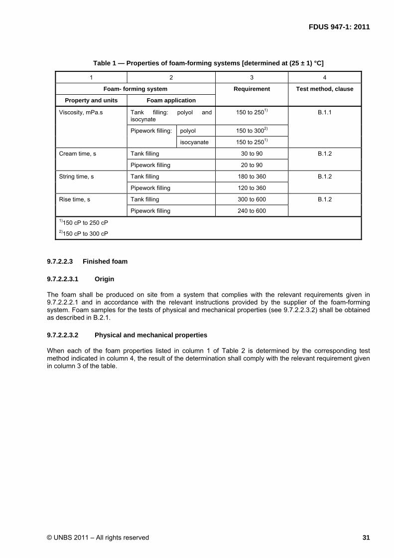
FDUS : 2011
© UNBS 2011 – All rights reserved 31
947-1
Table 1 — Properties of foam-forming systems [determined at (25 ± 1) °C]
1 2 3 4
Foam- forming system Requirement Test method, clause
Property and units Foam application
Viscosity, mPa.s Tank filling: polyol and isocynate
150 to 2501) B.1.1
Pipework filling: polyol 150 to 3002)
isocyanate 150 to 2501)
Cream time, s Tank filling 30 to 90 B.1.2
Pipework filling 20 to 90
String time, s Tank filling 180 to 360 B.1.2
Pipework filling 120 to 360
Rise time, s Tank filling 300 to 600 B.1.2
Pipework filling 240 to 600 1)150 cP to 250 cP 2)150 cP to 300 cP
9.7.2.2.3 Finished foam
9.7.2.2.3.1 Origin
The foam shall be produced on site from a system that complies with the relevant requirements given in 9.7.2.2.2.1 and in accordance with the relevant instructions provided by the supplier of the foam-forming system. Foam samples for the tests of physical and mechanical properties (see 9.7.2.2.3.2) shall be obtained as described in B.2.1.
9.7.2.2.3.2 Physical and mechanical properties
When each of the foam properties listed in column 1 of Table 2 is determined by the corresponding test method indicated in column 4, the result of the determination shall comply with the relevant requirement given in column 3 of the table.

32 © UNBS 2011 – All rights reserved
Table 2 — Physical and mechanical properties of foam
1 2 3 4
Foam
Requirement Determination Property and units Function
Density, kg/m3 Tank filling 30 to 401) B.2.2
Pipework filling 15 to 202)
Closed – cell content, % Tank filling > 80 B.2.3
Pipework filling > 20
Comprehensive strength, kPa
Tank filling > 150 B.2.4
Pipework filling > 20
Bending Properties
Deflection at break, mm Tank filling > 15 B.1.2
Pipework filling > 20
Force at Break, N, min1 Tank filling > 15 B.2.5
Pipework filling > 2
If the test breaks before reaching deflection of 20 mm ( see US ISO 1209-1)
1. 0.030 g/cm3 to 0.040 g/cm3
2. 0.015 g/cm3 to 0.020 g/cm3
9.7.2.2.3.3 Dimensional stability
When tested in accordance with B.2.6, the foam shall
a. exhibit no distortion, and
b. maintain its structural integrity.
9.7.2.2.3.4 Absence of volatile emissions
No chlorinated hydrocarbon vapours or formaldehyde, detectable by smell, shall be emitted by the foam at any time after the completion of its production.
9.8 Registration
Each installation shall be registered with the authority before being commissioned and receiving product to operate as per Petroleum Supply Act 2003.

FDUS : 2011
© UNBS 2011 – All rights reserved 33
947-1
Annex A (normative)
Design and construction of tanks
A.1 General
A.1.1 The minimum internal design pressure for a tank shall be equal to the static head measured from the top of the bulk delivery vehicle to the bottom of the installed tank.
A.1.2 A tank shall be capable of withstanding a working pressure (vacuum) of S20 kPa (that is,. atmospheric minus 20 kPa absolute).
A.1.3 A tank shall be able to resist the upward thrust of pressure generated by water surrounding the tank, taking due cognizance of any point loading imposed by the holding-down system.
A.1.4 A tank shall be able to withstand imposed loads generated by a legal maximum loaded wheel and axle system. A limit on the tank diameter might also be necessary if remote suction pumps are used instead of submersible pumps.
A.1.5 All tanks shall be internally free from loose dirt and foreign matter. All openings shall be sealed as soon as tests have been satisfactorily completed. Allowance shall be made for thermal breathing.
A.1.6 The manufacturer shall provide a general calibration chart per tank size.
A.1.7 The major dimensions of a tank shall be as specified by the purchaser.
A.2 Interceptors and drainage
A.2.1 Interceptors are different from gravity separators, in that they take effluent containing emulsifiers and detergents.
A.2.2 The interceptor shall take the floor washings from the lubricating bay and the workshop and effluent from the wash bay. The interceptor chamber shall be covered with a suitable manhole and shall be vented by a pipe of diameter at least 50 mm to an elevation of at least 3.6 m.
The depth of the interceptor chamber, measured from the invert of the outlet to the level of the bottom of the chamber shall be at least 600 mm. Increased depth does not improve the efficiency of the interceptor and complicates cleaning. The minimum plan area of the chamber shall be 800 mm × 800 mm.
A.2.3 Interceptor chambers shall be oil proof and waterproof and for this reason prefabricated units shall be considered.
A.2.4 A downstream sampling chamber of diameter 300 mm shall be provided for the purpose of sampling the effluent before it enters the foul sewerage system. The minimum retention volume shall be 32 R. The effluent can be sampled for the testing of chemical oxygen demand and, as a field indicator, dissolved oxygen.
A.2.5 In terms of the Petroleum Supply Act, 2003 used oil and paraffins may not be taken into this interceptor.

34 © UNBS 2011 – All rights reserved
A.3 Used oil and solvent washings (paraffins)
In terms of the Petroleum Supply Act, 2003, all used oil and contaminated used hydrocarbons shall be sold as waste to a licensed oil refiner or recycling plant.
At every installation, a system and facilities shall be provided for collecting and storing the waste products without spillage or infringement of the Water Act of 1956, and for removing the waste.

FDUS : 2011
© UNBS 2011 – All rights reserved 35
947-1
Annex B (normative)
PUR foam-forming systems and foams for filling abandoned tanks and
pipework — Test methods
B.1 Tests for foam-forming systems
B.1.1 Determination of viscosity at (25 ± 1) °C of the components (isocyanate and polyol) of a foam-forming system
Use the method in ISO 3219.
B.1.2 Determination of foaming characteristics at (25 ± 1) °C: cream time, string time and rise time
B.1.2.1 Apparatus
B.1.2.1.1 Laboratory apparatus
For small-scale preparation of PUR foam, comprising the following items:
a. mixer, operating within the rotational frequency range 24 s-1 to 29 s-1 (1 440 rpm to 1 740 rpm), equipped with an aluminium disc-type stirrer of diameter 65 mm;
b. balance, accurate to 0.1 g or better;
c. thermometer, reading accurately to within 0.5 °C or better, suitable for measuring temperature in a range encompassing 25 °C;
d. mixing container, polyethylene beaker, or a non-waxed cardboard container, of capacity 500 mR to 700 mR, and height of side wall preferably not greater than twice the diameter; and
e. glass rod or wooden spatula.
B.1.2.1.2 Stopwatch,
Reading accurately to 1 s or better
B.1.2.2 Test specimen
The components (isocyanate and polyol) of a foam-forming system (including any requisite minor additives) for the filling of a tank or pipework, as appropriate
B.1.2.3 Procedure
NOTE Isocynates are highly reactive chemicals, aggressive to the skin and eyes. It is essential to ensure that the person performing the foaming characteristics test is thoroughly familiar with the necessary safety precautions, and with procedures for dealing with accidental splashes and spills. The relevant instructions are obtainable from any reputable mmanufacturer of the isocyanate components of foam-forming systems.
B.1.2.3.1 Thoroughly stir each of the two liquid components of the foam-forming system to ensure their homogeneity.

36 © UNBS 2011 – All rights reserved
B.1.2.3.2 Check the temperature of each component and, if necessary, adjust it to a value between 24 °C and 26 °C by gentle warming or cooling with stirring.
B.1.2.3.3 Set up the stirrer for operation in the mixing container.
B.1.2.3.4 Weigh 25 g of the polyol into the mixing container.
B.1.2.3.5 Weigh out 30 g of the isocyanate and add it to the polyol in the mixing container. Immediately after this addition, start the stirrer and the stopwatch simultaneously.
B.1.2.3.6 Continue stirring the mixture in the mixing container for a total time of 15 s ± 1 s, then stop the stirrer (but not the stopwatch) and take it out of the container.
B.1.2.3.7 At the end of the stirring the mixture will be essentially clear. Watch it, and note the time at which it first turns cloudy ("creamy") and begins to expand. Record as the cream time (in seconds), the length of the period between this time and the time of the start of mixing (see B.1.2.3.5). Check the cream time so recorded for compliance with the relevant requirement given in table 1.
B.1.2.3.8 Continue watching the expanding mixture, checking at frequent intervals whether "strings" of the tacky material can be pulled away from the surface when it is touched with the spatula or glass rod.
NOTE The time of commencement of this stringing effect and record, as the string time (in seconds), the length of the period between this time and the time of the start of stirring (see B.1.2.3.5). Check the string time so recorded for compliance with the relevant requirement given in Table 1.
B.1.2.3.9 Continue watching the mixture in the container, and note the time at which the expansion in volume ceases, as indicated by the cessation of the upward movement of the top (the white-appearing "cap") of the rising foam. Record, as the rise time (in seconds), the length of the period between the start of stirring (see B.1.2.3.5) and the time at which the expansion stopped. Check the rise time so recorded for compliance with the relevant requirement given in Table 1.
B.1.2.3.10 If, after completion of expansion, the foam is to be used for determination of properties (see B.2.1), leave it to stand for at least 72 h before such use.
B.2 Determination of foam properties
B.2.1 Foam samples
Take foam samples from free-rise foam prepared as directed in B.1.2. Where so necessitated by the size and number of specimens required for a particular test, the size of container used and the amounts of foam-forming system components may be increased appropriately (in comparison with those given in B.1.2.1.1(d) and B.1.2.3.4 to B.1.2.3.5, respectively).cedure NOTE – Isocyanates are highly reactive chemicals, aggressive to the skin and eyes. It is essential to ensure that the person performing the foaming characteristics test is thoroughly familiar with the necessary safety precautions, and with procedures for dealing with accidental splashes and spills. The relevant instructions are obtainable from any reputable manufacturer of the isocyanate components of foam-forming systems.
B.2.2 Density of foam
Determine the foam density using the method in ISO 845. Check the result for compliance with the relevant requirement given in Table 2.
B.2.3 Closed-cell content
Determine the closed-cell content of the foam using method 2 of ISO 4590. Check the result for compliance with the relevant requirement given in Table 2.

FDUS : 2011
© UNBS 2011 – All rights reserved 37
947-1
B.2.4 Compressive strength
Determine the compressive strength of the foam, in the direction parallel to the direction of foam rise, using the method in ISO 844. Check the result for compliance with the relevant requirement given in Table 2.
B.2.5 Bending properties
Determine the bending properties of the foam using the apparatus and method in ISO 1209-1. Note that the specimens comprising one of the two sets of specimens prescribed by ISO 1209-1 shall be cut from the foam sample so that their longitudinal axes are parallel to the direction of rise of the foam, and the longitudinal axes of the specimens of the other set shall be normal to this direction.
Check the results of the determination for compliance with the relevant requirements given in Table 2.
B.2.6 Dimensional stability
Determine the dimensional stability of the foam using the method in DIN 53428, using the following reagents: water, gasoline and diesel oil, and expose the specimens for 28 d at 25 °C.
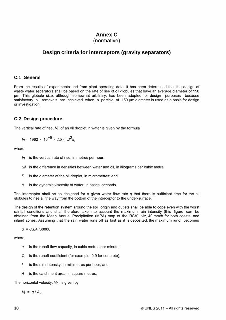
38 © UNBS 2011 – All rights reserved
Annex C (normative)
Design criteria for interceptors (gravity separators)
C.1 General
From the results of experiments and from plant operating data, it has been determined that the design of waste water separators shall be based on the rate of rise of oil globules that have an average diameter of 150 µm. This globule size, although somewhat arbitrary, has been adopted for design purposes because satisfactory oil removals are achieved when a particle of 150 µm diameter is used as a basis for design or investigation.
C.2 Design procedure
The vertical rate of rise, Vt, of an oil droplet in water is given by the formula
Vt= 1962 × 10−9 × ∆δ × D2/η
where
Vt is the vertical rate of rise, in metres per hour;
∆δ is the difference in densities between water and oil, in kilograms per cubic metre;
D is the diameter of the oil droplet, in micrometres; and
η is the dynamic viscosity of water, in pascal-seconds.
The interceptor shall be so designed for a given water flow rate q that there is sufficient time for the oil globules to rise all the way from the bottom of the interceptor to the under-surface.
The design of the retention system around the spill origin and outlets shall be able to cope even with the worst rainfall conditions and shall therefore take into account the maximum rain intensity (this figure can be obtained from the Mean Annual Precipitation (MPA) map of the RSA), viz, 40 mm/h for both coastal and inland zones. Assuming that the rain water runs off as fast as it is deposited, the maximum runoff becomes
q = C.I.A./60000
where
q is the runoff flow capacity, in cubic metres per minute;
C is the runoff coefficient (for example, 0.9 for concrete);
I is the rain intensity, in millimetres per hour; and
A is the catchment area, in square metres.
The horizontal velocity, Vh, is given by
Vh = q / Ac

FDUS : 2011
© UNBS 2011 – All rights reserved 39
947-1
where
Vh is the horizontal velocity, in metres per minute;
q is the runoff flow capacity, in cubic metres per minute; and
Ac is the cross-sectional area of the separator, in square metres.
An acceptable maximum horizontal velocity Vh, for the flow through an interceptor would be less than 0.91 m/min (3 ft/min or 55 m/h), or 15 Vt, whichever is the smaller.
The length of the separator, L, in metres, is given by
L = F (Vh/Vt ) × d
where
F is a design factor (dimensionless); and
d is the depth of the separator, in metres.
The design factor F is the product of the short-circuiting factor, Fsc, which can be taken as 1.2, and the turbulence factor, Ft, which is a function of the ratio of Vh to Vt:
F = Fsc × Ft
The American Petroleum Institute gives the following recommended values of turbulence factors:
Vh/Vt Turbulence factor, Ft 15 137
10 127
6 114
3 107
Furthermore, a separator shall be designed within the following limits:
a) a depth d of between 1 m (3 ft) and 2,4 m (8 ft);
b) a recommended depth-to-width ratio greater than 0.3 and less than 0.5 that is, d = 0.3 W to 0.5 W, where W is the width of the separator; and
c) a width W of between 2 m (6 ft) and 20 m (6 m).
C.3 Example
A separator is to be designed to cater for runoff from a concrete area 50 m × 45 m = 2 250 m2, assuming
a maximum rain intensity of 40 mm/h. The design temperature is 10 °C, and waste water through the separator contains diesel with a density of 860 kg/m
3 at 10 °C.
q = C.I.A./60000
= 0.9 × 40 × 2 250/60 000

40 © UNBS 2011 – All rights reserved
= 1.35 m3/min
Vt = 1,962 × 10−9 × ∆δ × D
2/η = 1,962 × 10
−9 × (997-860) × 1502/1,348 × 10
−3
= 4,487 m/h
= 0.0748 m/min
Vh = 15 Vt
= 1,122 m/min
which is greater than 0.91 m/min, therefore use Vh = 0.91 m/min as a maximum.
To avoid excessively long separators, Vh shall, in practice, be kept to a minimum. This can be done by increasing (within reason) the cross-sectional area of the separator.
Therefore assume
From
Then
d d W
Ac
=
=
=
=
1.3 m
0.5 × W
2.6 m
d.W =
=
1.3 × 2.6
3.38 m2
and
Vh
=
q / Ac = 1.35/3.38
0 4 / i
Hence
Vh/Vt
=
0.4/0.0748
= 5.34
By interpolation between the listed turbulence factors,
Ft = 1.125
so that
F = Fsc × Ft
= 1.2 × 1.125
= 1.35
This gives
L = F (Vh/Vt ) × d
= 1.35 × 5.34 × 1.3
= 9.37 m
Therefore, the final dimensions of the separator would be:

FDUS : 2011
© UNBS 2011 – All rights reserved 41
947-1
• length = 9.4 m;
• width = 2.6 m; and
• depth = 1.3 m.

42 © UNBS 2011 – All rights reserved
Bibliography
[1] ANSI/NFPA 329:1992, Underground leakage of flammable and combustible liquids
[2] API 5L:1995, Specification for line pipe
[3] BS 4994:1987, Specification for design and construction of vessels and tanks in reinforced plastics
[4] SABS 533-2:1982, Black polyethylene pipes for the conveyance of liquids – Part 2: High density black polyethylene pressure pipes
[5] SABS 763:1988, Hot dip (galvanized) zinc coatings (other than on continuously zinc-coated sheet and wire)
[6] SABS 1217:1984, The production of painted and powder-coated steel pipes
[7] SABS 064:1979, The preparation of steel surfaces for coating
[8] SABS 0129:1977, Plastics tape wrapping of steel pipelines
[9] SABS 0140-1:1978, Identification colour marking – Part 1: General
[10] SABS 0140-2:1978, Identification colour marking – Part 2: Identification of hazards and equipment in work situations
[11] SABS 0140-3:1992, Identification colour marking – Part 3: Contents of pipelines
[12] SABS 0214:198,The design, fabrication and inspection of articles for hot-dip galvanizing

FDUS : 2011
© UNBS 2011 – All rights reserved 43
947-1
Certification marking
Products that conform to Uganda standards may be marked with Uganda National Bureau of Standards (UNBS) Certification Mark shown in the figure below.
The use of the UNBS Certification Mark is governed by the Standards Act, and the Regulations made thereunder. This mark can be used only by those licensed under the certification mark scheme operated by the Uganda National Bureau of Standards and in conjunction with the relevant Uganda Standard. The presence of this mark on a product or in relation to a product is an assurance that the goods comply with the requirements of that standard under a system of supervision, control and testing in accordance with the certification mark scheme of the Uganda National Bureau of Standards. UNBS marked products are continually checked by UNBS for conformity to that standard.
Further particulars of the terms and conditions of licensing may be obtained from the Director, Uganda National Bureau of Standards.

FDUS 947-1: 2011
ICS nn.nnn.nn
Price based on nn pages
© UNBS 2011 – All rights reserved