Embed Size (px)
Citation preview

Material Modeling
FDTD Solutions

© 2012 Lumerical Solutions, Inc.
Outline
Dispersive materials in a time domain method
Available material models
: How to choose the correct model
Anisotropic materials
Tips
: Getting better material fits
: Understanding the mesh order
: Nonlinear simulations

© 2012 Lumerical Solutions, Inc.
Dispersive materials in the time domain
Well-known frequency domain relationship
FDTD is a time domain technique: relationship?
)()()( ED
t
tdtttEtEttD
0
)()()()()(

© 2012 Lumerical Solutions, Inc.
Material models
Common models
• Dielectric
• PEC (Perfect Electrical Conductor)
• Sampled Material
Nonlinear & Advanced
• Chi2
• Chi2/Chi3
• Kerr nonlinear
• Paramagnetic
• Custom plug-in
These models are implemented via the custom material plug-in framework.
FDTD Solutions supports the following models
Other linear models
• Analytic
• (n,k) Dielectric
• Conductive
• Plasma
• Debye
• Lorentz
• Sellmeier

© 2012 Lumerical Solutions, Inc.
Material models
Dielectric Material There is no dependence on frequency! Restriction
: n >= 1
This model is used when selecting “<Object defined dielectric>” for the material property of a structure.
constant)( 2 nr

© 2012 Lumerical Solutions, Inc.
Material models
PEC (Perfect Electrical Conductor)
: Equivalent to a conductor with
0E

© 2012 Lumerical Solutions, Inc.
Material models – Sampled material
Sampled Material There is experimental (or theoretical, or user’s own) data
for (n,k) as a function of wavelength : From built-in material database : From your own data
FDTD Solutions automatically fits the data over the wavelength range of your sources : Multi-coefficient model : You choose
• The number of coefficients • The fit tolerance
: More coefficients takes more time and memory

© 2012 Lumerical Solutions, Inc.
Example GaAs, 12 coefficients
Material models – Fitting sampled data
GaAs, 200-800nm

© 2012 Lumerical Solutions, Inc.
Material models – Fitting sampled data
Fitting your (proprietary) data
: Example, representative data of color filters
Red filter

© 2012 Lumerical Solutions, Inc.
Material models – Fitting sampled data
Fitting your (proprietary) data
: Example, representative data of color filters
Blue filter

© 2012 Lumerical Solutions, Inc.
Material models – Fitting sampled data
Metals are not necessarily simple plasma materials
Chromium

© 2012 Lumerical Solutions, Inc.
Material models – Fitting tips Check the imaginary data to avoid “fake” gain
A fixed wavelength range for fitting can be specified
Imaginary part of permittivity can be overweighted or underweighted

© 2012 Lumerical Solutions, Inc.
Material models – Default materials
Built in material data with auto-fitting
NOTE:
Default material
properties cannot
be modified (but
copies can).
© 2012 Lumerical Solutions, Inc.
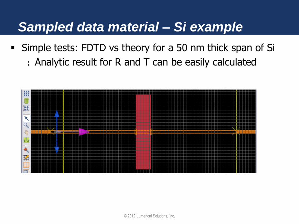
Sampled data material – Si example
Simple tests: FDTD vs theory for a 50 nm thick span of Si
: Analytic result for R and T can be easily calculated

© 2012 Lumerical Solutions, Inc.
Sampled data material – Si example
Simple tests: FDTD vs theory for a 50 nm thick span of Si
: multi-coefficient auto-fit to Si

© 2012 Lumerical Solutions, Inc.
Sampled data material – Si example
Simple tests: FDTD vs theory for a 50 nm thick span of Si
: Calculate the theoretical curve from the fit
: Average difference = 0.001
: Max difference = 0.008

© 2012 Lumerical Solutions, Inc.
Sampled data material – Si example Simple tests: FDTD vs theory for a 50 nm thick span of Si
: Calculate the theoretical curve from the original material data
: Average difference = 0.0023
: Max difference = 0.031
: Results come from one simulation

© 2012 Lumerical Solutions, Inc.
Sampled data material – Si example
Compare Lorentz model with multi-coefficient model
Lorentz model Multi-coefficient model

© 2012 Lumerical Solutions, Inc.
Material models – More linear models (n,k) Dielectric FDTD Solutions chooses the simplest dispersive model that can create the
correct permittivity (real and imaginary) at the center frequency of your simulation : Perfect for single wavelength simulations
At other frequencies, the value of (n,k) will be different : In reality, physical materials with loss are also dispersive
• More accurate broadband results can be obtained using actual material data and a Sampled Material
: Use the Materials Explorer to see the difference between target (n,k) and actual (n,k) for broadband simulations

© 2012 Lumerical Solutions, Inc.
Material models – More linear models
Analytic : The analytic material model allows the user to enter an equation
for the real and imaginary part of the permittivity or refractive index which can depend on a set of variables.
: A common use example for the analytic material model is for materials such as AlxGa1-xAs where the refractive index is a function of x. The analytic material makes it easy to change x in between simulations.

© 2012 Lumerical Solutions, Inc.
Material models – More linear models
Conductive f
ir
2
)(0
Debye
f
ic
cdebye
r
2
)(
Plasma (Drude)
f
i c
p
r
2
)(
2
Lorentz
f
i
lorentzr
2
2)(
2
0
2
0
2
0

© 2012 Lumerical Solutions, Inc.
Material models – More linear models
Sellmeier
: fs is center frequency of the sources in your simulation : The resulting material is not dispersive! : Should be used for single wavelength simulations only : Typically used in MODE Solutions to calculate fiber dispersion
s
s
s
s
s
s
s
s
f
c
C
B
C
B
C
BAconstn
3
2
2
3
2
2
2
2
1
2
2
11
2

© 2012 Lumerical Solutions, Inc.
Material models – Nonlinear models
Kerr Chi3
)()()(2
)3()1( tEtEtP o
Chi2*
)()()( )2()1( tEtEtP iioi
Chi2/Chi3 *
)()()()(2)3()2()1( tEtEtEtP iiioi
Nonlinear Chi models (instantaneous)
* Implemented with material plug-in framework

© 2012 Lumerical Solutions, Inc.
Material models – Nonlinear models
)()(
)()(
0
0
tHtB
tEtD
r
r
Paramagnetic *
* Implemented with material plug-in framework
Multi-level multi-electron *
Coming soon…

© 2012 Lumerical Solutions, Inc.
Material models – Nonlinear models
Create your own!
Eg: Negative index, gain saturation, complex Chi
Plugin to create your own polarization update
It will be added to any existing material update
Write a C++ method with inputs a, b, En-1
Solve the following equation for
Trivial example
b
a 0
nn P
E
a
b
n
nn
E
EP 0
http://docs.lumerical.com/en/fdtd/ref_matdb_user_defined_models.html

© 2012 Lumerical Solutions, Inc.
Tips – Material Explorer
Check your material models before running simulations!
Particularly for Sampled data materials
Adjust number of coefficients and tolerance if necessary

© 2012 Lumerical Solutions, Inc.
Tips – Material Explorer
Beware of errors in the data, and using too many coefficients
Removing noise from data and correcting errors will improve the fit

© 2012 Lumerical Solutions, Inc.
Sampled data – Gold Mie example
Example Mie Scattering, gold sphere
A good test case because analytic solution exists
© 2012 Lumerical Solutions, Inc.
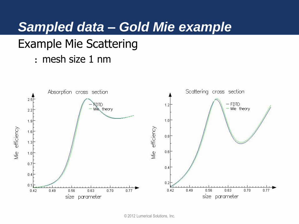
Sampled data – Gold Mie example
Example Mie Scattering
: mesh size 1 nm
© 2012 Lumerical Solutions, Inc.
Material models - Review
What built-in materials are available?
What material model should I use?
How do I define my own dispersive materials?
Cautions about divergence!! : Some models created by the Sampled Material auto-fit will
diverge. Can be fixed by • Reducing the “dt stability factor”
• Reducing “PML sigma” and increasing “PML Kappa” where materials intersect the PML boundary condition, or preventing materials from intersecting the PML
• See docs.lumerical.com/en/fdtd/user_guide_diverging_simulations.html for more details

© 2012 Lumerical Solutions, Inc.
Anisotropic Materials
TOPICS
Anisotropic materials
: introduction
: in FDTD Solutions
Example
© 2012 Lumerical Solutions, Inc.
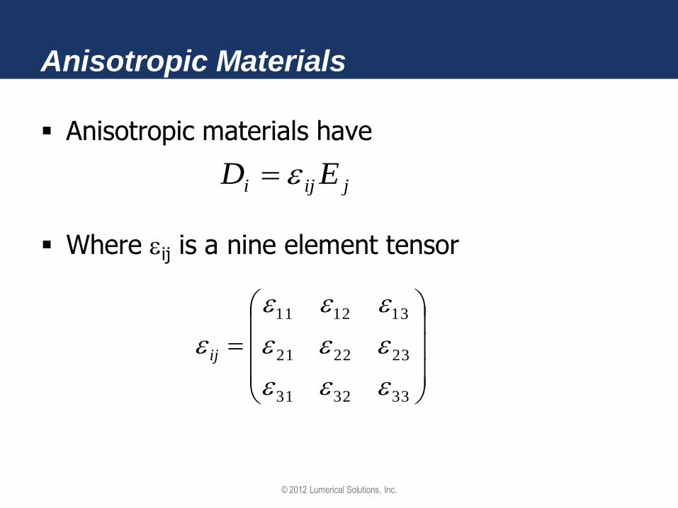
Anisotropic Materials
Anisotropic materials have
Where ij is a nine element tensor
333231
232221
131211
ij
jiji ED

© 2012 Lumerical Solutions, Inc.
Anisotropic Materials
Diagonal permittivity tensor
: In the Material Database, set the Anisotropy field to Diagonal, then specify the three diagonal terms.
z
y
x
00
00
00

© 2012 Lumerical Solutions, Inc.
Anisotropic Materials
Full permittivity tensor : First, diagonalize the anisotropy (use the eig script command) and find
both the eigenvalues and the unitary transformation that makes the permittivity diagonal.
: Create a new material in the Material Database using the diagonalized permittivity tensor.
: Use the Matrix transform grid attribute feature to apply the unitary transformation
: Example: http://docs.lumerical.com/en/fdtd/anisotropy_faraday_effect.html
UU
z
y
x
00
00
00†
333231
232221
131211

© 2012 Lumerical Solutions, Inc.
Anisotropic Materials
Example: open the file anisotropy1.fsp
nxx = 2, nyy=2, nzz=1
Ex Ez

© 2012 Lumerical Solutions, Inc.
Anisotropic Materials
What kind of anisotropy is available in FDTD Solutions?
How do I define anisotropic materials?
Relevant examples
: Faraday effect
: Magneto-optical Kerr effect
: Liquid crystals
http://docs.lumerical.com/en/fdtd/anisotropy.html
© 2012 Lumerical Solutions, Inc.
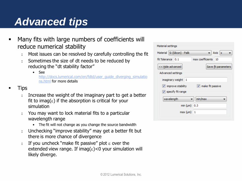
Advanced tips
Many fits with large numbers of coefficients will reduce numerical stability : Most issues can be resolved by carefully controlling the fit
: Sometimes the size of dt needs to be reduced by reducing the “dt stability factor”
• See http://docs.lumerical.com/en/fdtd/user_guide_diverging_simulations.html for more details
Tips
: Increase the weight of the imaginary part to get a better fit to imag() if the absorption is critical for your simulation
: You may want to lock material fits to a particular wavelength range
• The fit will not change as you change the source bandwidth
: Unchecking “improve stability” may get a better fit but there is more chance of divergence
: If you uncheck “make fit passive” plot over the extended view range. If imag()<0 your simulation will likely diverge.

© 2012 Lumerical Solutions, Inc.
Advanced tips
Tips
: If you combine results from several different bandwidth simulations, you may want to lock the simulation meshing algorithm to use a larger wavelength range that encompasses all the wavelengths you want to study
: This means that the FDTD mesh will not change as you change the source bandwidth
© 2012 Lumerical Solutions, Inc.
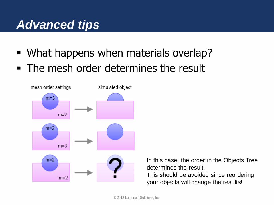
Advanced tips
What happens when materials overlap?
The mesh order determines the result
In this case, the order in the Objects Tree
determines the result.
This should be avoided since reordering
your objects will change the results!
© 2012 Lumerical Solutions, Inc.
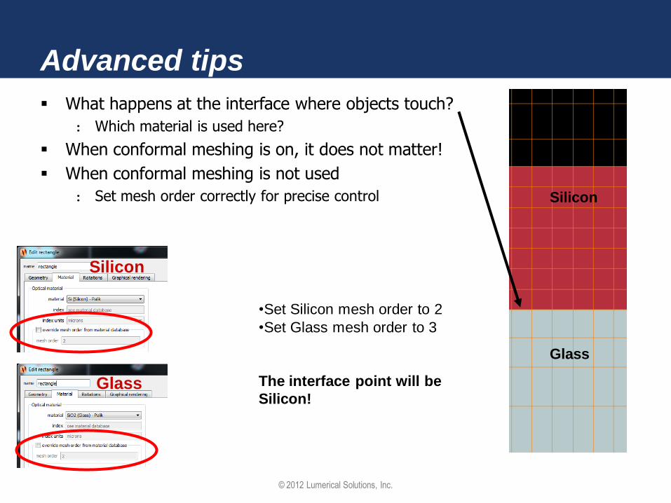
Advanced tips
What happens at the interface where objects touch?
: Which material is used here?
When conformal meshing is on, it does not matter!
When conformal meshing is not used
: Set mesh order correctly for precise control
Silicon
Glass
•Set Silicon mesh order to 2
•Set Glass mesh order to 3
The interface point will be
Silicon!
Silicon
Glass

© 2012 Lumerical Solutions, Inc.
Advanced tips
Nonlinear simulations can be
substantially more complicated
to setup, analyze and to ensure
convergence, compared to a
similar linear simulation.
See the following link for a number of important tips related to
setting up nonlinear simulations
http://docs.lumerical.com/en/fdtd/nonlinear_tips.html

© 2012 Lumerical Solutions, Inc.
Questions and Answers…

© 2012 Lumerical Solutions, Inc.
Getting help
Technical Support
: Email: [email protected]
: Online help: docs.lumerical.com/en/fdtd/knowledge_base.html
• Many examples, user guide, full text search, getting started, reference guide, installation manuals
: Phone: +1-604-733-9006 and press 2 for support
Sales information: [email protected]
Find an authorized sales representative for your region:
: www.lumerical.com and select Contact Us