Embed Size (px)
Citation preview
FDM of ABS Patterns for Investment Casting
By
Paul Blake* Eric Fodran"" Martin Koch"" Unny Menon"" Bill Priedeman*
Stephen Sharp""
*STRATASYS
"" CALIFORNIA POLYTECHNIC STATE UNIVERSITY, SAN LUIS OBISPO
ABSTRACTThis paper will evaluate the suitability of fused deposition modeling (FDM) of
acrylonitrile butadiene styrene (ABS) patterns for use in investment casting. The focus ison integration with existing foundry practices. It is a combined industry/universityproject with the case studies performed at the industrial sites with university producedpatterns. Process parameters, ash handling and casting issues are addressed.
195
2 INTRODUCTIONFused deposition modeling (FDM) has demonstrated the ability to reduce
production time requirements in many applications. Like other forms of rapidprototyping, FDM provides a means of directly creating a tangible 3D object from aCAD/CAM image. On average when compared to machining, FDM has provided amethod ofverifying designs quickly and often, for a low relative cost. Additionaldecreases in production time can be obtained, if the FDM Acrylinitrile butadiene styrene(ABS) builds were used as the investment casting patterns. The feasibility of this isdetermined by addressing casting issues, ash handling, and process parameters, as wellas, through thermal analysis and macroscopic examination.
3 GOALSOur goals are to present casting guidelines for the average Investment Casting
Foundry (IC) to use with the ABS patterns. These guidelines involve the use of simpletechniques and common materials, and have generally resulted in successful castings.
4 CASTING ISSUESIn order for ABS casting patterns to reduce the investment casting time cycle,
ABS must be easily useable with standard practices. Therefore, pattern preparation,gating and venting, investing, burn-out, ash removal, and casting must be consideredwhen determining ifABS is a usable alternative to wax.
4.1 Pattern PreparationThe ABS patterns are robust and easy to work with. They sand well and can be
machined. They can be modified with wax to improve surface finish, and combined withwaxes to form composite patterns.
4.2 Gating and VentingFor ABS patterns, traditional gating and venting practices require some
modifications. These changes can easily be adapted to IC, and must be followed in orderto obtain adequate ash removal. It is during the gating and venting design process thatthe modifications are first introduced.
Ash removal will require low air pressure and water rinsing. Therefore, it isnecessary to install additional vents on the pattern. This will improve the air and waterfeature penetration during the ash removal process. A fair amount of access to theinterior of the mold structure is also gained by cutting open the gate end. This too willincrease the efficiency and ease of the ash removal. Consequently, it is also important todesign the investment tree with the idea that the gate and vent ends will be removed priorto the burn-out process.
Once the investment tree design has been established, standard IC technique isused to attach the gates and venting.
4.3 InvestingA cleaning/etching agent is normally applied to the investment tree prior to
shelling. This provides a means of removing any release agents. Once the
196
cleaning/etching agent has dried, standard investment casting procedures are followed inproducing the shell. Generally an FDM investment shell is composed of, first, threenormal layers, followed by three layers with steel wire reinforcement, with a final sealcoat then applied. The number of reinforcing layers can be increased to strengthen theshell when necessary.
After the final seal coat has dried, the tips of the vents are ground to expose thewax. The main sprue is also ground exposing the wax. This modified investing step,must be performed prior to the burn-out cycle.
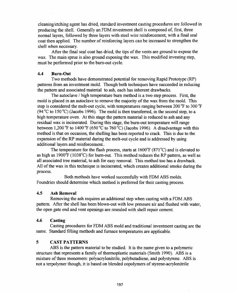
4.4 Burn-OutTwo methods have demonstrated potential for removing Rapid Prototype (RP)
patterns from an investment mold. Though both techniques have succeeded in reducingthe pattern and associated material to ash, each has inherent drawbacks.
The autoclave / high temperature burn method is a two step process. First, themold is placed in an autoclave to remove the majority of the wax from the mold. Thisstep is considered the melt-out cycle, with temperatures ranging between 200 OP to 300 OF(94°C to 150°C) (Jacobs 1996). The mold is then transferred, in the second step, to ahigh temperature oven. At this stage the pattern material is reduced to ash and anyresidual wax is incinerated. During this stage, the burn-out temperature will rangebetween 1,200 of to 14000P (650°C to 760°C) (Jacobs 1996). A disadvantage with thismethod is that on occasion, the shelling has been reported to crack. This is due to theexpansion of the RP material during the melt-out cycle and is addressed by usingadditional layers and reinforcement..
The temperature for the flash process, starts at 16000P (871°C) and is elevated toas high as 19000P (1038°C) for burn-out. This method reduces the RP pattern, as well asall associated tree material, to ash for easy removal. This method too has a drawback.All of the wax in this technique is incinerated, which creates additional smoke during theprocess.
Both methods have worked successfully with FDM ABS molds.Foundries should determine which method is preferred for their casting process.
4.5 Ash RemovalRemoving the ash requires an additional step when casting with a FDM ABS
pattern. After the shell has been blown-out with low pressure air and flushed with water,the open gate end and vent openings are resealed with shell repair cement.
4.6 CastingCasting procedures for FDM ABS mold and traditional investment casting are the
same. Standard filling methods and furnace temperatures are applicable.
5 CAST PATTERNSABS is the pattern material to be studied. It is the name given to a polYmeric
structure that represents a family of thermoplastic materials (Smith 1990). ABS is amixture of three monomers: polyacrylonitrile, polybutadiene, and polystyrene. ABS isnot a terpolYffier though, it is based on blended copolymers of stYrene-acrylonitrile
197

(70:30) and butadiene-acrylonitrile (65:35) and on graft interpolymers of styrene andacrylonitrile with polybutadiene (Smith 1990) (Sharp 1990). By adding modifiers to thebasic ABS mixture, the material properties can be altered. Consequently, the ABSmaterial being evaluated should be the same material that is used during the productionofa FDM build.
6 THERMALANALYSffiThermogravimeteric Analysis Systems (TGA) have proven effective for
temperature related polymeric degradation studies. The TGA is designed to measure thechange in the sample's mass with respect to the temperature of its environment, even ifthat environment is altered (Kelen 1983). Several methods can be used to alter theenvironment: varying the temperature, introducing reactive gases into the samplechamber or a combination of these variables.
After determining the appropriate test parameters, two samples are selected forexposure. The first specimen is the actual sample material; contrarily, the other is inertto the test environment. The inert sample, known as the reference sample, provides areference point during thermal analysis.
6.1 Graphical InterpretationMost TGA systems also provide the derivative of the thermogravimeteric curve
(DTG) and label the curve, the Differential Thermal Analysis (DTA). The DTA providesinformation on endothermic or exothermic reactions in the sample material. This isdepicted by plotting the change in temperature measurements for the sample against theunaffected reference sample. The endothermic and exothermic points are then useful indetermining the temperature at which deterioration of the material properties occurs(Kelen 1983).
7 MACROSCOPIC EXAMINATIONMacroscopic examination is one of the most basic forms ofvisual examination
available. Often used as a prelude to microscopic studies, macroscopic inspection canalso be used alone. In this case, inspection of the cast parts will be visually inspected,unless it is deemed necessary to examine a part in greater detail.
8 EXPERIMENTATIONSeveral builds were produced using the Stratysis 1600. These builds were then
used as investment casting patterns and for thermal analysis. The two different types ofbuilds produced were the 3D Systems "Nine-Wall" patterns, seen in figure 1, and theStratysis "Turbine" pattern, seen in figure 2.
8.1 CASTINGEach sample requires some preparation work prior to casting. Sanding was not
required, but a utility knife was used to shave plastic stringers and remove some oftheABS support material. A small screwdriver was also utilized to remove some of the ABSsupport material from the patterns. The final preparation requirement for each pattern
198

was to fill the small surface openings with paste wax. Approximately 20 minutes wasrequired to prepare each pattern for investing.
Figure 1 - FDM Nine-Wall ABS pattern
Figure 2 - The as cast turbine pattern onthe left and ABS turbine pattern on theright
Some of the patterns were provided to Aurora Engineering for use as castingpatterns. A design that would be capable of providing adequate access for ash removalwas determined first. The investment tree design and venting arrangement are show infigure 3. The investment tree was composed of a styrofoam core with a wax coating.Addition venting is also evident in figure 3:> from the increase in the bleeder wax:> that ispositioned around the ABS pattern.
Figure 3 - Nine-Wall pattern ready forinvesting
Figure 4 - Invested pattern with gate endand vents opened
The entire investment tree was sprayed with isopropyl alcohol and allowed to dry,in preparation for the investing process. Once the investment tree had dried:> it wasdipped in a coating solution a total of seven times: three normal coats, three coats withsteel wire added, and then one final coat. The final invested pattern is shown in figure 4.The ends of the vents and gates have been removed to aid in subsequent ash removal.Burn-out was performed using the flash process. The molds were placed in a preheated
199
furnace at 1600OP(8710C), immediately raised to 19000P (1038°C) and left for 90minutes. After burn-out, the ash (a light white powder) was remove with low-pressureair and water. Mold repair cement was then used to reseal the vent and gate ends.
Standard casting procedures were then followed and aluminum was cast into themolds. The molds at the time of casting were preheated to 12000P (649OP) and thealuminum was poured at 12850P (696°C).
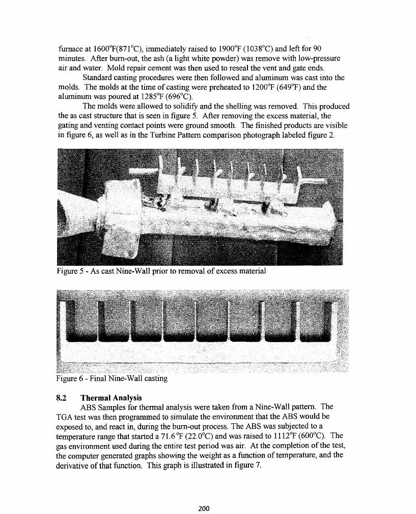
The molds were allowed to solidify and the shelling was removed. This producedthe as cast structure that is seen in figure 5. After removing the excess material, thegating and venting contact points were ground smooth. The finished products are visiblein figure 6, as well as in the Turbine Pattern comparison photograph labeled figure 2.
Figure 5 - As cast Nine-Wall prior to removal of excess material
Figure 6 - Final Nine-Wall casting
8.2 Thermal AnalysisABS Samples for thennal analysis were taken from a Nine-Wall pattern. The
TGA test was then programmed to simulate the environment that the ABS would beexposed to, and react in, during the burn-out process. The ABS was subjected to atemperature range that started a 71.6 OP (22.0°C) and was raised to 1112'}' (600°C). Thegas environment used during the entire test period was air. At the completion of the test,the computer generated graphs showing the weight as a function of temperature, and thederivative of that function. This graph is illustrated in figure 7.
200

Figure 7 - TGA results showing degradation and exothermic peaks
9 RESULTS AND DISCUSSIONThe FDM ABS builds all performed successfully as IC patterns. The ABS
patterns, which were built at an academic institution, were transferred to industry andeasily assimilated into the IC process.
Upon visual inspection of the final IC cast products, surface appearance wasfound to be acceptable, and an example of the surface is shown in figure 8. The surfacesin the cast products may be improved further, by increasing the time spent preparing thesurfaces of the patterns. Fine, thin wall details, as in the fins on the Nine-Wall patternand the Turbine pattern, as seen in figures 9 and 2 respectively, were accuratelyreplicated. The only noticeable imperfection was found at the tip ofone fin. This wasmost likely due to the fin cooling too quickly and the metal solidifying before it hadcompletely filled this given area, a cold short.
The TGA confirmed that the ABS material bum-out process is above the requiredtemperature for ABS to degrade. As was evident from figure 7, degradation of the plasticoccurs at approximately 797<>P (425°C). This is displayed by the exothermic reaction andis estimated from this figure.
201
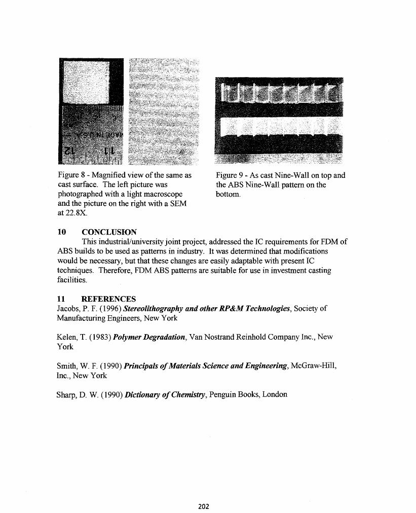
Figure 8 - Magnified view ofthe same ascast surface. The left picture wasphotographed with a light macroscopeand the picture on the right with a SEMat 22.8X.
Figure 9 - As cast Nine-Wall on top andthe ABS Nine-Wall pattern on thebottom.
10 CONCLUSIONThis industriaVuniversity joint project, addressed the IC requirements for FDM of
ABS builds to be used as patterns in industry. It was determined that modificationswould be necessary, but that these changes are easily adaptable with present ICtechniques. Therefore, FDM ABS patterns are suitable for use in investment castingfacilities.
11 REFERENCESJacobs, P. F. (1996) Stereolithography and other RP&M Technologies, Society ofManufacturing Engineers, New York
Kelen, T. (1983) Polymer Degradation, Van Nostrand Reinhold Company Inc., NewYork
Smith, W. F. (1990) Principals ofMaterials Science and Engineering, McGraw-Hill,Inc., New York
Sharp, D. W. (1990) Dictionary ojChemistry, Penguin Books, London
202