Embed Size (px)
Citation preview
Page 1
Facilities Development Manual Wisconsin Department of Transportation Chapter 13 Drainage Section 1 Drainage Practice
FDM 13-1-1 Drainage Practice Background December 18, 2015
1.1 Introduction
The Director of the Bureau of Project Development (BPD) is the originator of this chapter.
1.2 General
Drainage has long been recognized as one of the primary considerations of highway construction. Its importance can be noted from the cost involved in providing drainage facilities for the highway, and for this reason alone a careful and scientific approach to drainage design should be taken. The purpose of this chapter is to provide a guide to existing standard procedures for drainage design throughout the state. The goal of design is to plan optimum drainage facilities considering function versus cost while meeting environmental requirements.
The methods of hydrologic and hydraulic analysis provided in this chapter will give the designer information necessary for drainage analysis. Experience and sound engineering judgment are not to be ignored and may at times differ from results obtained using methods in this chapter. Careful weighing of experience, judgment, and procedure are necessary for optimal drainage design. Terminology that is unique to this chapter and to "drainage" in general is defined in Attachment 1.1.
1.3 Basic Statewide Practice
In designing highway drainage systems, the three major considerations are:
1. The safety of the traveling public;
2. The use of sound engineering practices to economically protect and drain the highway;
3. In accordance with reasonable interpretation of the law, the protection of private property from flooding, water-soaking, or other damage.
In general, the hydraulic adequacy of pipe culverts shall be determined by the region based on sound hydrologic and hydraulic techniques and performance records at the same or similar locations. No improvement in the drainage of areas outside the right-of-way should be considered unless the state would benefit thereby or the project is financed by others.
1.4 Design Responsibility
The Bureau of Structures (BOS) is responsible for the hydraulic and structural adequacy of all cast-in-place and precast box culverts and bridges. Preliminary hydrologic and hydraulic computations for such structures shall be performed by BOS or consultant staff. A hydraulic/sizing report shall be prepared by BOS or consultant designers (refer to FDM 13-1-10, and Chapter 8 (hydraulics) of the LRFD Bridge Manual).
In addition, a Structure Survey Report is required for all hydraulic structures designed or reviewed by BOS. Refer to Chapter 6 of the department's LRFD Bridge Manual for report procedures. The region is responsible for the hydraulic adequacy of all other types of drainage structures.
BOS should be notified whenever it is proposed to replace an existing bridge with a pipe culvert(s) so that records of existing bridges may be kept current. Refer to the bridge manual for bridge definition:
http://wisconsindot.gov/Pages/doing-bus/eng-consultants/cnslt-rsrces/strct/bridge-manual.aspx
The Statewide Drainage Engineer in the Bureau of Project Development shall be notified when plans include the box-shaped storm sewer. The Statewide Drainage Engineer will consult with the Bureau of Structures to determine the design requirements for the storm sewer and whether a structure number will be assigned.
1.5 Common Drainage Law
Drainage Common law is that body of principles found in court decisions based on customs, practices, and precedents that have evolved and are unwritten in statute or code.
According to Harold H. Ellis (1), Wisconsin's common law rules relating to diffused surface waters are as follows:
1. A lower owner may legally treat diffused surface waters as his enemy and prevent them from coming
FDM 13-1 Drainage Practice
Page 2
onto his land.
2. The upper owner has a right to alter the natural flow of diffused surface waters and may discharge them upon lower land, subject to the following limitations:
- The water must be expelled onto the lower land without malice.
- The actions of the upper owner may extend no further than reasonably necessary to protect himself or his land.
- Such water may not be diverted into another watershed.
- The upper owner may not unduly collect such waters in a pond or reservoir and thereafter discharge them on his neighbor's land or on his own land in such close proximity to his neighbor that they will inevitably permeate and percolate so as to permanently injure the neighbor's soil.
Because the upper owner must not be negligent and he must be reasonable in his use and improvement of his land, Wisconsin has moved to a middle ground, lying somewhere between the "common enemy rule (2)” and the "reasonable use rule (2)".
1.6 Statutory Drainage Law
When the Department of Transportation constructs a highway, the natural or pre-existing flow of surface water might be changed, and the effects of these changes might extend beyond the highway right-of-way to private property. The laws governing these matters are found in Chapter 88 of the Wisconsin Statutes, Drainage of Lands.
Section 88.87 of this chapter states that a highway "...shall not impede the general flow of surface water or stream water in any unreasonable manner so as to cause either an unnecessary accumulation of waters flooding or water-soaking uplands or an unreasonable accumulation and discharge of surface waters flooding or water soaking lowlands." It further states that these highways "...shall be constructed with adequate ditches, culverts, and other facilities as may be feasible, consonant with sound engineering practices, to the end of maintaining as far as practicable the original flow lines of drainage." The section also provides that drainage rights or easements may be purchased or condemned to aid in the prevention of damage to property owners, which might otherwise occur as a result of the highway construction. (WisDOT does not intend to acquire easements as a routine solution to drainage problems (refer to FDM 13-1-5, Drainage Rights and Easements).
It is the duty of every landowner to provide, and at all times to maintain, a sufficient drainage system to protect the highway from water damage or flooding, by directing the flow of surface waters into existing highway drainage systems or by permitting the flow of such water away from the highway. Chapter 86, Section 86.07 (2) states that “no person shall make any excavation or fill or install any culvert or make any other alteration in any highway or in any manner disturb any highway or bridge without a permit therefore from the highway authority maintaining the highway.”
In addition to Chapter 88, Section 86.075 covers the responsibility of a highway authority to notify the county drainage board "Whenever a highway crossing any draining ditch of a drainage district governed by Chapter 88 is being constructed or reconstructed or a culvert in any such ditch is being replaced, the highway authority in charge of such work shall consult with the drainage board having jurisdiction of such district for the purpose of determining the depth at which such drainage ditch was laid out." If any culvert or similar opening in a highway is installed at a grade higher than the depth at which a drainage ditch was laid out, the expenses involved in any future lowering of the culvert pursuant to Section 88.68 (4) shall be borne by the unit of government in charge of maintenance of the highway.
The Wisconsin State Statutes, Chapter 146, Miscellaneous Health Provisions also state, in Section 146.13; "Discharging noxious matter into highway and surface waters (1) If anyone constructs or permits any drain, pipe, sewer or other outlet to discharge into a public highway infectious or noxious matter, the board of health of the village, town or city shall, and the town sanitary district commission or the county board of health, acting alone or jointly with the local board of health may, order the person maintaining it to remove it within 10 days..." This Section further states (2)" No person shall discharge by any means whatsoever untreated domestic sewage into any surface water as defined by s. 144.01(5), or drainage ditch governed by ch. 88; nor shall any person discharge effluents or pumpage by any means whatsoever from any septic tank, dry well or cesspool into any surface water as defined by s. 144.01(5), or drainage ditch governed by ch. 88 ..."
The Wisconsin State Statutes, Chapter 236, Platting Lands and Recording and Vacating Plats, state, in Section 236.13, that “approval of the preliminary or final plat shall be conditioned upon compliance with: ...(e) The rules of the Department of Transportation relating to provisions for the preservation of the public interest and investment in such highways.” This department rule is TRANS 233 that states as one of its basic principles: one of its basic principles in 233.02 (5) “A land division map shall include provisions for the handling of surface drainage in such a manner as specified in s TRANS 233.105 (3).” Section 233.105 (3) states (3) Drainage - The
FDM 13-1 Drainage Practice
Page 3
owner of land that directly or indirectly discharges storm water upon a state trunk highway or connecting highway shall submit to the department a drainage analysis and drainage plan that assures to a reasonable degree, appropriate to the circumstances, that the anticipated discharge of storm water upon a state trunk highway or connecting highway following the development of the land is less than or equal to the discharge preceding the development and that the anticipated discharge will not endanger or harm the traveling public, downstream properties or transportation facilities. Various methods of hydrologic and hydraulic analysis consistent with sound engineering judgment and experience and suitably tailored to the extent of the possible drainage problem are acceptable. Land dividers are not required by this subsection to accept legal responsibility for unforeseen acts of nature or forces beyond their control. Nothing in this subsection relieves owners or users of land from their obligations under S.88.87 (3)(b), stats.
Note: In section 88.87 (1), Stats., the Legislature has recognized that development of private land adjacent to highways frequently changes the direction and volume of flow of surface waters. The Legislature found that it is necessary to control and regulate the construction and drainage of all highways in order to protect property owners from damage to lands caused by unreasonable diversion or retention of surface waters caused by a highway and to impose correlative duties upon owners and users of land for the purpose of protecting highways from flooding or water damage. Wisconsin law, section 88.87 (3), Stats., imposes duties on every owner or user of land to provide and maintain a sufficient drainage system to protect downstream and upstream highways. Wisconsin law, section 88.87 (3)(b), Stats., provides that whoever fails or neglects to comply with this duty is liable for all damages to the highway caused by such failure or neglect. The authority in charge of maintenance of the highway may bring an action to recover such damages, but must commence the action within 90 days after the alleged damage occurred. Section 893.59, Stats.
The plats should be reviewed to ensure they conform to this principle.
For further details on drainage law, the designer is referred to:
- Wisconsin State Statutes, “Miscellaneous Highway Provisions,” Chapter 86.
- Wisconsin State Statutes, “Floodplain Zoning,” Chapter 87.
- Wisconsin State Statutes, “Drainage of Lands,” Chapter 88.
- Wisconsin State Statutes, "Water, Sewage, Refuse, Mining and Air Pollution," Chapter 144.
- Wisconsin State Statutes, "Miscellaneous Health Provisions,” Chapter 146.
- Wisconsin State Statutes, “Platting Lands and Recording and Vacating Plats,” Chapter 236.
- Wisconsin Administrative Code, Chapter TRANS 233.
REFERENCES
(1) Ellis, Harold H.; Beuscher, J.H.; Howard, Cletus D.; De Braad, J. Peter; "Water-Use Law and Administration in Wisconsin," Department of Law, University Extension, The University of Wisconsin, First Edition, 1970, 694 pp.
(2) "Guidelines for the Legal Aspects of Highway Drainage," Volume V-Highway Drainage Guidelines, AASHTO, 2007, 24 pp.
LIST OF ATTACHMENTS
Attachment 1.1 Glossary of Terms
FDM 13-1-5 Major Drainage Guidelines and Criteria March 31, 2017
5.1 Definition
This procedure defines the major drainage issues and sets guidelines and criteria for more detailed studies, when appropriate. More detailed studies, when required, are completed in the design phase of project development. Three basic questions are asked:
1. Are major drainage problems anticipated?
2. Are the available general drainage guidelines appropriate for solving the anticipated problems?
3. What are the surface drainage alternatives?
These questions should be asked and resolved at the region. The Bureau of Project Development function is to update and clarify the major drainage guidelines, as necessary.
5.2 General Guidelines
To clarify the study of major drainage, it is helpful to consider some typical guidelines. For the most part, these
FDM 13-1 Drainage Practice
Page 4
are statutory "guidelines" or traditional practices set up by the Department of Transportation. They are broad practices, the changing of which would have an immediate, statewide effect on adjacent properties. Therefore, they are not subject to random change by either the region or the central office.
The general guidelines are:
1. Water Accumulation: The highway shall not impede the general flow of surface water or stream water in any unreasonable manner so as to cause either an unnecessary accumulation of waters flooding or water-soaking uplands, or an unreasonable accumulation and discharge of surface waters flooding or water-soaking lowlands (from Section 88.87, Wisconsin Statutes). This objective should be accomplished by:
- Anticipating the amount and frequency of storm runoff.
- Determining natural points of concentration and discharge and other hydraulic controls.
- Determining the necessity for protection from floating trash and debris.
- Comparing and coordinating proposed design with existing drainage structures and systems handling the same flows.
- Removing detrimental amounts of surface and subsurface water.
- Providing the most efficient disposal system consistent with economy, the importance of the road, maintenance, and legal obligations.
- Culverts designed with the intent to permanently impound water may be regulated by WDNR as dams. In general, this situation should be avoided because of the potential regulatory issues and the potential barrier to aquatic organism passage. The Statewide Drainage Engineer in Bureau of Project Development should be notified of any culvert designed to permanently impound water.
2. Drainage Districts: Any work that involves drainage districts must be coordinated with the county drainage board of such district. The legal procedures for these cases are set forth in Chapter 86 of the Wisconsin Statutes and ATCP 48 of Wisconsin Administrative Code (refer to FDM 5-15-1).
3. WisDOT and Wisconsin Department of Natural Resources (WDNR) Cooperative Agreement: The Department of Transportation shall design and construct drainage facilities in accordance with the spirit and intent of the WisDOT and WDNR Cooperative Agreement, a copy of which can be found in FDM 20-30-1.
4. 401 and 404 Permits: The necessity of 401 and 404 permits for a drainage facility should be determined by FDM 21-30-1.
5. Local Sewerage Commissions: Coordinate work with local sewerage commissions that are affected by the project.
6. Aquatic Organism Passage: The crossing of some streams by highways requires the construction of drainage facilities that will accommodate aquatic organism passage. In addition, other streams may require the construction of barriers at drainage structures in order to prevent the migration of rough fish or other invasive species. In the early stages of design, the WDNR shall be consulted when streams are involved that might require special drainage facilities. Moreover, if aquatic organism passage facilities are required at a drainage structure, a field review regarding questions on aquatic organism passage should be held with the WDNR. For culvert design including aquatic organism passage, the designer should consult with the Statewide Drainage Engineer responsible for AOP coordination.
7. Drainage Patterns: Highway reconstruction projects should match natural drainage patterns as closely as possible. New culverts should be located and designed to minimize change or disruption in the natural flow of water, commensurate with cost.
When the highway is in fill, the amount of special ditching along the fill slope should be minimized except where required to protect the adjacent land.
When a highway is constructed on relocation, changes in surface drainage are more significant. Culverts should be placed at natural draws or depressions. Culverts should be placed frequently enough to avoid excessive concentration of flow.
8. Headwater: Criteria for culvert headwater is generally set as 1.5 times the pipe diameter, or no overtopping of roadway for design storm event, provided there is no risk of damage to adjacent upstream property. Headwater elevation shall have no rise in mapped zoned floodplains unless all requirements of the WisDOT/WDNR Cooperative Agreement are met.
9. Drainage Rights and Easements: Wisconsin Statutes provide WisDOT with the authority to acquire
FDM 13-1 Drainage Practice
Page 5
drainage rights and easements. However, WisDOT does not intend to acquire easements unless it is determined that significant damage would occur to private property or that the cost of a larger structure (designed to accommodate the regional flood) would not be justified.
10. Overflow Section: These sections are considered for special situations (refer to FDM 13-10-1).
11. Maintenance Considerations: For future maintenance considerations the designer should provide:
- Sufficient erosion protection for channel banks, for the highway, and for culvert outlets to prevent scour or erosion on private land.
- Large enough culverts for ease of maintenance.
- Curbs or berms and downslope pipe or gutters along fills of erodible material.
- Drainage easements wide enough for maintenance equipment.
- Access at drainage facilities for power equipment.
- Debris catches where needed.
- Corrosion-resistant structures in areas with corrosive soils and waters.
- Interceptor ditches along the top of cut slopes.
- Necessary drainage structures should be located, if possible, beyond the clear zone (refer to FDM 11-15-1). Where this is not possible, suitable protective barriers should be provided.
5.3 Surface Data Collection
5.3.1 Probable Working Media for Major Drainage Studies
The designer will usually be working from an aerial mosaic with a scale of 1" = 200' to 1" = 800' (1:2400 to 1:9600). LiDAR elevation data and 2-foot contours are available for many counties through data-sharing agreements. Countywide digital orthophotos may be obtained through the USDA NAIP at:
www.wisconsinview.org
Soils data can be found in NRCS Soil Survey Maps and digitally from the NRCS Geospatial Data Gateway.
5.3.2 Input Data Requirements
Desirable data will be of a general nature, as follows:
1. Watershed characteristics
2. Stream crossing locations
3. Climate information
4. Limiting design factors
5. Information on existing structures that would be readily available from logs, etc.
6. General information from local sources as to history of flooding and obvious problem areas.
7. Land use/cover
8. Soils data
5.3.3 Output Data
Desirable output data requirements are as follows:
1. Design discharge.
2. Proposed facilities.
3. Drainage easements.
4. Cost.
FDM 13-1-10 Documentation of Hydrologic/Hydraulic Design December 18, 2015
10.1 Introduction
Documentation of all hydrologic data and hydraulic design computations shall be assembled for each project and retained in the project files at the Region office. This documentation should contain all pertinent information used to design the drainage facilities and should be extensive enough to verify at a later date the hydraulic design of any structure. It should also include any information about special commitments placed on the project
FDM 13-1 Drainage Practice
Page 6
for environmental or public involvement reasons.
The Stormwater-Drainage-Water Quality (WQ) Report Spreadsheets along with the Channel and Chute Design Spreadsheet Worksheets are required.
Hydrology and hydraulic design documentation is to be stored in the Region Central file system for25 years (Refer to RDA 00145-000, Roadway Drainage Hydrologic & Hydraulic Studies and Design Calculation). The documentation must be provided to the project manager, who will send it to the Region Central file system.
10.2 Bridge and Box Culvert Design
The hydraulic design documentation for a bridge, box culvert or other large drainage conduit requiring structural analysis shall contain a segment entitled "Discussion of Structure Sizing.” This discussion should concisely summarize the engineering judgments that determined the structure size (waterway opening). Relevant factors to be highlighted include: relative construction cost considerations, environmental concerns, compatibility with local floodplain zoning ordinances, and risk considerations such as minimization of flooding, potential damages to abutting property, and protection of the motorist and/or highway.
A stream crossing structure survey report (SSR) should be prepared by the Region and forwarded to the Bureau of Structures (BOS) if the structure is to be designed by BOS. If the structure is to be designed by a consultant, the SSR should be submitted to BOS for review along with the preliminary structure plans and the hydraulic/sizing. Referred to in the preceding paragraph. See Chapter 8, Appendix A, of the WisDOT LRFD Bridge Manual for a sample hydraulic report (referred to as a "Sample Bridge Site Report").
BOS will perform the hydraulic/hydrologic analysis for all bridges and box culverts that are designed by the Department. Consultants are responsible for the hydraulic/hydrologic analysis of the bridges and box culverts they design.
10.3 Stormwater Report Applicability
Each WisDOT project that has a stormwater component must have a completed Stormwater-Drainage-Water Quality (WQ) Report spreadsheet. A Stormwater-Drainage-WQ Report is not needed for projects that have no change to the culvert or storm sewer system that drains the project or for projects that do not trigger TRANS401 water quality requirements. Typically, traffic control, ITS (Intelligent Transportation Systems), signalization, or safety projects will not need a stormwater report. Overlay projects that do not include culvert replacements, extensions, or other modifications are also exempt from the stormwater reporting requirement.
The Drainage Summary Worksheet should be submitted at the 30% design stage to describe any significant flow changes and what may need to be done to address the changes in flow. The intent of this early submittal is to note potential drainage problems at an early stage. The updated Summary Worksheet and the initial Data Worksheet should be submitted at the 60% design stage. This submittal should address the concerns brought up in the previous Drainage Summary Worksheet, any new issues, and include available information in the Data Worksheet. This submittal should also include any available drainage calculations or model analyses and drainage mapping. The final design submittal includes the completed Drainage Summary and Data Worksheets as well as all supporting documentation needed to review the worksheets.
The stormwater report spreadsheet is not applicable to bridges and box culverts designed or reviewed by Bureau of Structures nor is it applicable to storm sewer design.
10.4 Design Documentation
Each WisDOT project that has a stormwater component must develop a design for those components that includes the basin hydrology and the structure or system hydraulic design. The type and extent of the documentation for these components will vary, but the basic information includes the hydrology and hydraulic design information listed below. A summary of this information should be included in the Drainage-Stormwater Report spreadsheet described below. This spreadsheet provides a way for a designer to methodically describe the objectives and design of a project drainage system.
Hydrology
1. Design frequencies.
2. Methods used to compute the flow rates and the limitations of these methods.
3. The type and extent of future development and how it was considered in the design process.
4. List of all graphs that were used to determine rainfall depth, rainfall intensity, runoff, and time of concentration.
5. Any information that is used by the designer as general criteria for the determination of flow rates for ditches and culverts.
FDM 13-1 Drainage Practice
Page 7
6. Location map indicating each drainage area. Show the drainage areas in the form of a mosaic on a 1 inch = 100-foot, (1:1200) scale, photogrammetric, contour map. Large drainage areas should be shown on USGS contour maps.
7. A statement of the characteristics of the drainage pattern with regard to soil types, land usage and relief, special controls on the flow rates, possible future development effects, past flood of record, and any information that is needed to properly analyze the flow rate for the given drainage area and detailed computations of the flow rate.
Hydraulic Design
1. Detailed hydraulic design for each culvert location and each channel and ditch on the project.
2. A statement on any information gathered during the field review of the drainage area.
3. For culverts, provide the design work sheet or the computer design sheet for the culvert, which should contain information on the discharge, allowable headwater elevation, design headwater elevation, design tail-water depth, entrance conditions, grade of flow line, discharge velocity, freeboard (allowable headwater-roadway elevation), etc. This sheet should show designs for various types of inlet conditions and culvert materials, along with the final recommendation of the culvert used in the final design.
4. For storm sewer systems, include the urbanization factors, cost analysis, and any other factors that may affect the final design of the storm sewer. Provide a layout of the storm sewer system along with the contributing drainage areas, and a detailed design tabulation sheet showing the grate inlets, flow rates contributing to each inlet, and pipe sizes.
This documentation, initiated during the preliminary design stage, must be updated to reflect the final design. The stage of the design can be noted in the Drainage-Stormwater Report submittal described below on the Drainage-Summary worksheet.
As part of design documentation, the designer should determine whether a project is located within a regulatory floodplain. Unofficial floodplain maps can be viewed on WDNR’s Surface Water Data Viewer:
http://dnr.wi.gov/topic/surfacewater/swdv/
Official Flood Insurance Rate Maps can be viewed and printed in “FIRMette” form at FEMA’s Map Service Center under the Product Catalog at:
https://msc.fema.gov/
10.5 Stormwater-Drainage-WQ Report Spreadsheet Instructions for Drainage Design
There are two components to the spreadsheet: drainage and water quality. This section describes how to fill out the stormwater drainage worksheets of the report. Refer to FDM 10-30-1 for instructions on how to fill out the water quality worksheet sections of the Report.
The stormwater drainage section of the spreadsheet has two parts. The first part, which is on the ‘Drainage-Summary’ worksheet tab, is the Summary worksheet. This worksheet includes basic project information, (project name, limits, county, etc.) and a list of questions that will help the designer determine the drainage requirements for the project.
The second part of the stormwater drainage is a table of the stormwater flow and drainage issues that typically occur in a project. This list is in the ‘Drainage-Data’ worksheet tab and includes the following topic areas:
1. Outfall Information
2. Basic Subbasin Drainage Information
3. Urban/ and/or TRANS 401 Project Information (see FDM Chapter 10 for TRANS 401 requirements)
4. Culvert Design
a. Existing Culvert Data
b. Proposed Culvert Design
c. Floodplain Management
d. Drainage District Issues
e. Aquatic Organism Passage
5. Culvert Liner Design
FDM 13-1 Drainage Practice
Page 8
a. Existing Culvert Data
b. Liner Details
c. Floodplain Management
d. Drainage District Issues
e. Aquatic Organism Passage
The spreadsheet includes an outline feature that allows the user to collapse topic groups that are not relevant for the project to make the worksheet easier to use.
There are ten worksheets in the Stormwater-Drainage-WQ Report spreadsheet. The Stormwater Water Quality Summary worksheet and the water quality control practice worksheets, which all begin with the letters ‘WQ’, are discussed in FDM 10-30-1. The Drainage-Summary worksheet and the Drainage-Data worksheet are described below.
10.5.1 Drainage Summary Worksheet
This worksheet includes basic project information and a Drainage Summary page that includes questions that address drainage issues (refer to Attachment 10.1 and 10.2). Water quality questions and issues are addressed in FDM 10-30-1. Be sure to enable the spreadsheet Macros by clicking on the security warning "options" box on the top of the spreadsheet and then highlight the "enable this content" button.
10.5.1.1 Basic Project Information
Basic project information includes information like the project number and name. When entering this information, only enter it in columns B and C of this worksheet; the appropriate information will be copied to other worksheets by the spreadsheet.
Please note that the planning stage generally includes only the water quality component of stormwater management unless drainage considerations are part of a planning study.
10.5.1.2 Drainage - Summary Narrative The drainage summary narrative begins with line 15 on the "Drainage-Summary" tab of the stormwater report spreadsheets. This narrative is a series of questions that will, when completed, define the drainage goals, objectives, and issues for the project and how they were met. Enter your response in the cell below each question. Line 15: IS THERE A SIGNIFICANT FLOW INCREASE OR DECREASE WITHIN ANY SUB BASIN? IF YES,
DESCRIBE THE REASON. This question is intended to describe why any significant (greater than 5%) flow increases or
decreases occur in the project. Examples of an explanation and justification could include “Outfall 3: New connection to municipal storm sewer system" or “Outfall 8: Outfall location shifted and combined with adjacent upstation drainage basin to avoid concentrated discharge to wetland.
Line 17: IS THERE A SIGNIFICANT IMPERVIOUS AREA CHANGE TO ANY SUB BASIN? IF YES, DESCRIBE THE REASON. Increases in impervious surface area are often the result of added lanes, new alignment, or park and ride lots, etc. However, the impact on peak rate discharge may be insignificant if the impervious area is a small portion of the subbasin or if the impervious area is located near the outfall. Increased impervious surface will increase the runoff volume. The impact of the increased impervious area may be significant if the overall drainage basin is small or if the added discharge from the impervious area reaches the outfall at the same time as the peak flow from the balance of the drainage bas
Line 19: HAVE THE DRAINAGE SUB BASIN AREAS OR FLOW PATHS CHANGED SIGNIFICANTLY? IF YES, DESCRIBE THE REASON.
Altered flow paths may change the size of the drainage basin and affect the downstream drainage system. Existing ponds and wetlands may be affected if tributary drainage is relocated. Peak discharge rate increase may increase the potential for streambed erosion. Document the reason for the drainage area re-routing, and describe erosion control plans to address increased peak discharge rates.
Line 21: DESCRIBE THE PROPOSED DRAINAGE CONVEYANCE AND CONTROL SYSTEMS. The conveyance system may include any combination of drainage swales, culverts and/or storm
sewers. Control systems may include detention ponds, diversion structures, etc. Line 23: DESCRIBE ANY AQUATIC ORGANISM PASSAGE ISSUES. If one or more culverts in the project require aquatic organism passage design, describe the water
FDM 13-1 Drainage Practice
Page 9
body classification, the requesting agency, and reason for request. Complete the AOP section of the Stormwater Report Drainage-Data section for the culvert(s).
Line 25: DESCRIBE ANY EXCEPTIONS TO WisDOT FDM CHAPTER 13 DRAINAGE REQUIREMENTS, Document and explain any exceptions to the FDM Chapter 13 drainage design requirements.
Examples may include the use of 12-inch diameter storm sewer pipes or wide-bottom special ditches. Line 27: DESCRIBE WDNR COORDINATION.
Provide name of WDNR liaison, date of correspondence, and attach printed copy of correspondence. Line 29: DESCRIBE ACCOMMODATIONS TO MEET LOCAL, MUNICIPAL, OR REGIONAL DRAINAGE OR
STORMWATER MANAGEMENT THAT EXCEED FDM CHAPTER 13 REQUIREMENTS. Sometimes accommodations are made to meet drainage design standards that exceed WisDOT FDM
Chapter 13 design requirements. For example, a community may want a detention pond to decrease peak flows in the off-DOT ROW drainage area, or may want all drainage structures in their jurisdiction to meet their higher design standards so the entire drainage system meets a consistent set of standards. If this occurs, document the accommodation, why it was made, and the source of funding for the modifications.
Line 31: DOCUMENT SIGNIFICANT IMPACTS TO THE PROJECT CAUSED BY DRAINAGE, PROJECT MANAGER CONCURRENCE IS REQUIRED. (PM SIGN AND DATE).
The project manager must acknowledge any significant drainage impacts or non-standard design changes to the project by signing this report or providing documented concurrence using, for example, an email message stating he or she has reviewed and approved of the report.
10.5.1.3 Drainage - Data Worksheet
The number of columns in the worksheet can increase as needed by highlighting the last unfilled column and dragging the small box in the lower right hand corner of the highlighted column to the right. The outfall numbers will increase consecutively.
As noted in FDM 13-1-10.4, there are a number of headings in the Drainage-Data spreadsheet. This section will review the contents of each heading.
If an explanation is required as part of the response to a line item in the report, provide the explanation on a separate attachment.
Section 1: Outfall Information:
Lines 8 – 28 should be completed for all outfalls, regardless of whether culverts or storm sewer system. Documentation for storm sewer systems should be attached to the Stormwater Report, but no information past Line 28 is necessary in the Stormwater Report.
Line 8: Outfall number. Consecutively numbered outfalls from the start to the end of the project. An outfall is any culvert,
roadside ditch, or storm sewer drainage discharge point with runoff either originating from or passing through the project right-of-way.
Line 9: Outfall discharges to: Use the pull down menu to select the type of water body the outfall discharges to. The options are: 1)
Overland, 2) Ditch, 3) Creek, 4) River, 5) Wetland, 6) Storm Sewer, 7) Combined Sewer, 8) Other. Line 10: Waterway crossing type: Use the pull down menu to select the type of waterway crossing. The options are: 1) Culvert, 2) Box
Culvert, 3) Storm Sewer, 4) Three Sided Box Culvert, and 5) Bridge. Line 11: If discharging to environmentally sensitive area, what kinds of buffers were used at outfall? The options in the pull down menu are: 1) Swales, 2) Filter Strips, 3) Vegetated Embankment. Line 12: Previous flooding issues or flow restrictions? Select yes or no from the pull down menu. If yes, provide explanation. Line 13: Is the drainageway in the DOT ROW a navigable waterway? Select yes or no from the pull down menu. Line 14: Classify the drainageway in the DOT ROW. The options are: 1) Wetland, 2) 303(d) Waters, 3) Exceptional Waters, 4) Outstanding Waters, 5)
Waters of the U.S.
Section 2: Basic Sub Basin Drainage Information:
Line 16: Outfall number.
Consecutively numbered outfalls from the start to the end of the project. An outfall is any culvert,
FDM 13-1 Drainage Practice
Page 10
roadside ditch, or storm sewer drainage discharge point with runoff either originating from or passing through the project right-of-way.
Line 17: Outfall station. The station along the reference line where the outfall is located. Line 18: Design storm frequency. Enter the flood frequency used for the design of the culvert or storm sewer system. This value is
typically found in FDM 13-10 Figure 1.1. Line 19: Check storm frequency. Enter the flood frequency used to check the design for unacceptable inundation of the highway facility
or flooding. Refer to FDM 13-25-20 for additional information. Line 20: Drainage area (ac). Line 21: Hydrologic Method. List the method used to compute the peak discharge rates for the design and check storms. Examples
include, but are not limited to: the Rational Method, TR20/55, HEC-1/HMS, regional regression equations, and basin transfer methodology.
Line 22: Time of Concentration (min). The time required from discharge to travel from the most hydrologically remote point in the drainage
area to the outfall. Line 23: C or CN. Runoff coefficient, C, for use with the Rational Method can be found in FDM 13-10 Attachment 5.2,
and Runoff Curve Numbers, CN, for use with TR20/55 can be found in FDM 13-10 Attachment 5.6. Line 24: Rainfall Intensity (in/hr). Rainfall intensity is used with the Rational Method for hydrologic computations, and can be found
using the Intensity-Duration-Frequency (IDF) curves in FDM 13-10 Attachment 5.4. Line 25: Rainfall Depth (in) For hydrologic methods using a design storm to determine the peak discharge rate, record the rainfall
depth of the design storm. SCS Type II distribution corresponds to National Weather Service Technical Paper 40 (1959) rainfall totals.
NOAA Atlas 14 rainfall data may be used with the WDNR and SEWRPC distributions, and require that a critical storm duration analysis be completed. MSE-3 and MSE-4 24-hour rainfall distributions replacing SCS Type II are available from NRCS for use with the NOAA Atlas 14 rainfall data at:
http://www.nrcs.usda.gov/wps/portal/nrcs/detail/wi/technical/engineering/?cid=nrcs142p2_025417
Line 28: Hydraulics design software used. Record the design software used for drainage analysis and design. Section 3: Urban/TRANS 401 Project Information:
This section, including lines 29-43 of the stormwater/drainage report form, is required only for urban projects or projects with TRANS 401 water quality requirements.
Line 31: DOT right of way area (acres). Enter the area draining to the outfall that is within the WisDOT right-of-way. Line 32: DOT right-of-way compared to sub-basin drainage area (%) (calculated). This value is self-populated based on data in Lines 20 and 31. The relative drainage area information
may be used when negotiating storm sewer cost share agreements between WisDOT and a municipality.
Line 33: DOT impervious area – existing (acres). Enter the existing (pre-project) impervious surface area within the WisDOT right-of-way to outfall. Line 34: DOT impervious area – proposed (acres). Enter the proposed impervious surface area within the WisDOT right-of-way to outfall. Line 35: Change in impervious area (calculated).
This value is self-populated based on data in Lines 33 and 34. This information may be used to determine possible reason for change in discharge and potential downstream impacts.
Line 36: Percent change DOT in impervious area (calculated). This value is self-populated based on data in Lines 33 and 34. This information may be used to
determine possible reason for change in discharge and potential downstream impacts. Line 37: Proposed peak discharge rate (cfs), before detention
FDM 13-1 Drainage Practice
Page 11
Design peak flow for the proposed drainage system, not including impacts of detention. Line 38: Peak discharge rate change (cfs). This value is self-populated based on data in Lines 26 and 37. Line 39: Percent change peak discharge rate (%). This value is self-populated based on data in Lines 26 and 37. Line 40: Design peak discharge rate (cfs) post-detention: Enter the design peak discharge rate for the proposed drainage system post-detention. If there is no
detention, then this value is the same as the value in Line 37. Line 41: Existing 2-year peak discharge flow (cfs): The pre-project 2-year peak discharge rate for the drainage system. Line 42: Proposed 2-year peak discharge flow (cfs) The post-project, pre-detention 2-year peak discharge rate for the proposed drainage system. Line 43: Proposed 2-year peak flow (cfs), (after detention,/in-line storage/other). The design peak discharge rate for the proposed drainage system after any detention/ in line/other
storage. If there is no detention, then this value is the same as the value in Line 42. Section 4: Culvert Replacement/Extension Project Information
Culvert Design – Existing Culvert Line 52: Manning's n: Roughness values for common culvert materials can be found in Table B.1 of FHWA HDS-5. Line 53: Inlet configuration: Typical inlet configurations can be found in FHWA HDS-5, Chapter 1, Section 3.3. Choices in the drop
down menu include: apron endwalls, mitered to slope, headwall, projecting. Line 54: Upstream invert (ft) Elevation of bottom of culvert at upstream end. Line 55: Downstream invert (ft). Elevation of bottom of culvert at downstream end. Line 56: Length (ft). Culvert length, not including apron endwalls or headwalls. Line 57: Slope (%) Value automatically calculated by dividing invert elevation difference by pipe length. Line 58: Computed upstream water surface elevation (ft). Upstream water surface elevation computed for design peak discharge using hydraulic computation
program in steady state analysis mode or FHWA HDS-5 nomograph methodology. Line 59: Tailwater elevation (ft). Water surface elevation at pipe outlet, based on normal depth of downstream channel or average of
critical depth and culvert diameter. See FHWA HDS-5 for more detail. Line 60: Outlet velocity (ft/s)
Water velocity at outlet end of pipe.
Culvert Design – Proposed Culvert Line 62 to 82: Proposed culvert information. Lines 63-72 contain similar inventory of physical properties as lines 48-57 for the existing culvert. Line 76: Change in upstream water surface elevation. Value automatically computed comparing Line 77 and Line 58. Note that increases in upstream water
surface elevation are generally discouraged, and may be prohibited without “appropriate legal arrangement” in mapped floodplains.
Line 77: Riprap outfall. Size of riprap at culvert outfall, if necessary. Line 78: Maximum allowable headwater (ft) The maximum upstream water surface elevation. Line 79: Maximum allowable headwater design criteria. Drop down menu includes options of: existing conditions, shoulder subgrade point, or edge of
pavement elevation, or headwater to culvert diameter ratio. Line 80: Station of lowest subgrade shoulder point.
FDM 13-1 Drainage Practice
Page 12
The sag point of the vertical curve over the proposed culvert. Line 81: Elevation of lowest subgrade shoulder point (ft). Top of subgrade at sag point of vertical curve. Line 82: Headwater to pipe diameter ratio. Value is automatically calculated based on depth at upstream end (highwater elevation minus invert
elevation) divided by the culvert diameter or height. Culvert Design - Floodplain Management Line 84: Mapped floodplain. To determine if the culvert is in a mapped floodplain, either check with the region stormwater engineer
or view unofficial maps on the Wisconsin DNR Surface Water Data Viewer - FEMA Maps/DFIRMS at:
http://dnrmaps.wi.gov/sl/?Viewer=SWDV&layerTheme=1
Official Flood Insurance Rate Maps (FIRMs) can be found on FEMA’s website at:
http://msc.fema.gov/portal
Line 85: Increase in headwater. If there is an increase in water surface elevation, attach an explanation for the change and how the
increased water surface profile was approved. Culvert Design – Drainage District Issues
Line 87: Is culvert in a drainage district?
To determine if the culvert is in a drainage district, check with the region stormwater engineer or go to the web site:
https://datcpgis.wi.gov/maps/?viewer=dd
Line 89: Increase in headwater
If there is an increase in water surface elevation, attach an explanation for the change and how the increased water surface profile was approved.
Line 90: Drainage board approval?
Drainage board approval is required for increases in water surface profiles in areas located within incorporated drainage districts.
Culvert Design – Aquatic Organism Passage
Line 92: Is aquatic organism passage (AOP) a concern?
If AOP is considered in project, please include a copy of the WDNR Initial Review Letter.
Line 93: Does WDNR concur with the AOP design?
Provide documentation of WDNR concurrence.
Line 94: Embedment Depth
The depth of the inverts below the natural stream channel.
Line 95: Embedment Material
Description of the gradation of material in culvert. The material should match the native streambed material to the extent possible.
Section 5: Culvert Liner Design
Lines 99 – 133 should be completed for any project that includes a culvert liner.
Culvert Liner Design - Existing Culvert
Line 99: Outfall number.
Consecutively numbered outfalls from the start to the end of the project. This value is auto-populated.
Line 105: Manning’s roughness
Use standard values for “n” (i.e. 0.013 for concrete, 0.024 for corrugated metal)
Line 106: Pipe geometry
Cross sectional shape of pipe (i.e. circular, elliptical, arch, etc.)
FDM 13-1 Drainage Practice
Page 13
Line 107: Upstream invert
Elevation of the upstream end of the pipe.
Line 108: Downstream invert
Elevation of the downstream end of the pipe.
Line 109: Length (ft)
Length of pipe, not including endwalls or aprons
Line 110: Slope (%)
Automatically populated based on invert elevations and pipe length.
Line 111: Depth of cover over pipe (ft)
Minimum depth at between roadway surface and top of pipe
Line 112: Is overtopping an issue?
Based on observed erosion or reports of local residents, document any past observed overtopping.
Line 113: Upstream flooding risk?
Note and buildings or infrastructure that may be at risk if upstream water surface elevations are increased as a result of lining the culvert.
Culvert Liner Design - Floodplain Management
Line 125: Is the culvert in a mapped floodplain?
Select the pull down menu to answer either ‘Yes’ or ‘No’. To determine if the culvert is in a mapped floodplain, either check with the region stormwater engineer or go to the Wisconsin DNR Surface Water Data Viewer – FEMA Maps/DFIRMS at:
http://dnrmaps.wi.gov/sl/?Viewer=SWDV&layerTheme=1
Official Flood Insurance Rate Maps (FIRMs) can be found on FEMA’s website at:
http://msc.fema.gov/portal
Line 126: Will proposed liner increase water surface profile?
Select the pull down menu to answer either ‘Yes’ or ‘No’. If the answer is yes, attach an explanation of the reason for the change and how the increased water surface profile was approved.
Culvert Liner Design – Drainage District Issues
Line 128: Is culvert in a drainage district?
Select the pull down menu to answer either ‘Yes’ or ‘No’. To determine if the culvert is in a drainage district, either check with the region stormwater engineer or go to the web site:
https://datcpgis.wi.gov/maps/?viewer=dd
Line 129: Drainage District name.
Enter the name of the drainage district.
Line 130: Has the drainage board approved the use of a liner?
Select the pull down menu to answer either ‘Yes’ or ‘No’. If the answer is no, attach an explanation of the reason why the drainage board did not approve the change.
Culvert Liner Design - Aquatic Organism Passage
Line 132: Is aquatic organism passage a concern?
Select the pull down menu to answer either ‘Yes’ or ‘No’. If the answer is ‘Yes’, respond to the question on Line 135.
Line 143: Does WDNR agree with the AOP design?
Select the pull down menu to answer either ‘Yes’ or ‘No’. If the answer is no, attach an explanation of the reason for why the WDNR did not approve the design.
10.5.2 Example Stormwater-Drainage-WQ Worksheet
A completed Stormwater - Drainage Worksheet example is provided within the downloadable zip Stormwater-Drainage files (refer to link at top of Attachment 10.1 and 10.2). It includes both an urban and a rural
FDM 13-1 Drainage Practice
Page 14
component. The first sheet is the drainage basin overview figure, which illustrates basins for the entire project. If the corridor is long, additional sheets may be appropriate. For this example, not all drainage areas and outfalls for the project are shown. The map sheets provide additional detail, at a closer scale, of the drainage system along the highway for selected basins. The map sheets are followed by a completed stormwater report that illustrates both grass swale and storm sewer drainage.
LIST OF ATTACHMENTS
Attachment 10.1 Stormwater-Drainage-WQ Report Spreadsheet: Drainage - Summary Worksheet
Attachment 10.2 Stormwater-Drainage-WQ Report Spreadsheet: Drainage - Data Worksheet
FDM 13-1-15 Culvert Material Selection Standard March 31, 2017
15.1 Application
In general, WisDOT has approved steel, aluminum, concrete and thermoplastic as suitable materials for culvert pipe. Coating systems for steel culvert pipe may be either zinc-coated (galvanized), aluminum or polymer. This procedure establishes criteria for selecting the proper combination of material and coating for different situations.
The standards in this procedure apply to all shapes of culvert pipe (circular, arch or elliptical) and to pipes in the range of 12 to 84 inches in diameter. The selection of larger drainage conduit is addressed in FDM13-1-20.
These standards are based on the expected service life of the material, the traffic volume to be supported and the location of the pipe. Service life depends primarily on how durable the material is when subjected to corrosive or abrasive site conditions. Service life also depends on the proper structural design and installation of the pipe. These factors are considered in the Fill Height Tables of FDM13-1-25 as well as the standard specifications and the appropriate special provisions for individual projects.
The following table defines abbreviations commonly used throughout this chapter.
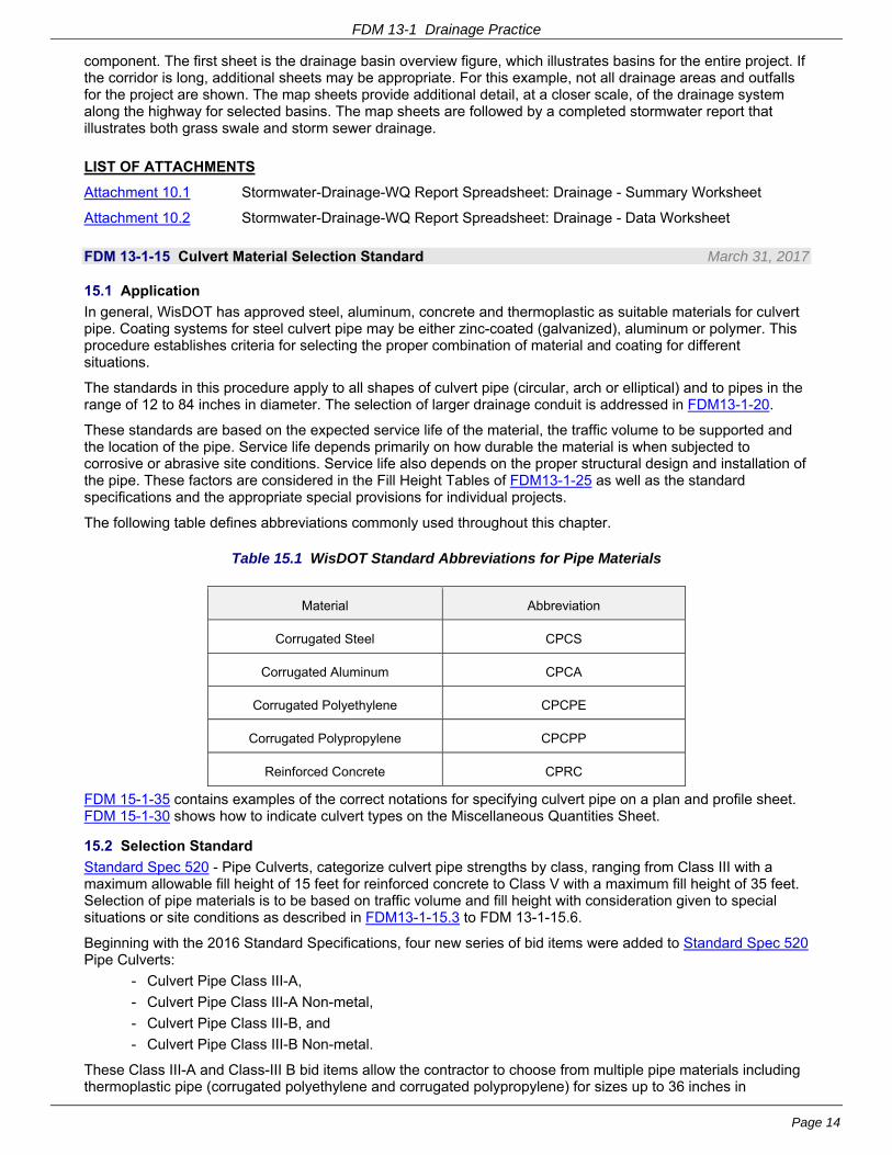
Table 15.1 WisDOT Standard Abbreviations for Pipe Materials
Material Abbreviation
Corrugated Steel CPCS
Corrugated Aluminum CPCA
Corrugated Polyethylene CPCPE
Corrugated Polypropylene CPCPP
Reinforced Concrete CPRC
FDM 15-1-35 contains examples of the correct notations for specifying culvert pipe on a plan and profile sheet. FDM 15-1-30 shows how to indicate culvert types on the Miscellaneous Quantities Sheet.
15.2 Selection Standard
Standard Spec 520 - Pipe Culverts, categorize culvert pipe strengths by class, ranging from Class III with a maximum allowable fill height of 15 feet for reinforced concrete to Class V with a maximum fill height of 35 feet. Selection of pipe materials is to be based on traffic volume and fill height with consideration given to special situations or site conditions as described in FDM13-1-15.3 to FDM 13-1-15.6.
Beginning with the 2016 Standard Specifications, four new series of bid items were added to Standard Spec 520 Pipe Culverts:
- Culvert Pipe Class III-A,
- Culvert Pipe Class III-A Non-metal,
- Culvert Pipe Class III-B, and
- Culvert Pipe Class III-B Non-metal.
These Class III-A and Class-III B bid items allow the contractor to choose from multiple pipe materials including thermoplastic pipe (corrugated polyethylene and corrugated polypropylene) for sizes up to 36 inches in
FDM 13-1 Drainage Practice
Page 15
diameter. Previously, corrugated polyethylene pipe was the only thermoplastic pipe that met one of the optional material requirements for Class III culvert pipes. As described in FDM 13-1-17.3.1, the intent of these Class III-A and Class-III B items is to introduce potential project cost reductions into the competitive bid process by allowing the contractor to select from multiple material options for pipes sized up to 36 inches.
The four subclasses of Class III culverts are as follows:
- Class III-A
- includes Class II and III reinforced concrete, corrugated steel, corrugated polyethylene, and corrugated polypropylene.
- Class III-A has a maximum fill height of 11 ft.
- Class III-B
- includes Class III reinforced concrete, corrugated steel and corrugated polypropylene
- Class III-B has a maximum fill height of 15 ft.
- Classes III-A, Non-metal and Classes III–B, Non-metal
- these non-metallic subclasses are for corrosive environments where it is not advisable to use metal pipe.
- therefore corrugated steel is removed.
As conditions allow, and with the exceptions listed, Culvert Pipe Class III-A, Culvert Pipe Class III-A Non-metal, Culvert Pipe Class III-B, and Culvert Pipe Class III-B Non-metal under Standard Spec 520 shall be specified for culverts where ADT is less than 7,000.
Reinforced concrete pipe is required for culverts under high volume roadways (ADT >7,000) because it is a proven and dependable material that is not likely to need replacement because of corrosion or substandard installation. Replacement of culvert pipe under a high volume roadway is costly and disruptive to the traveling public.
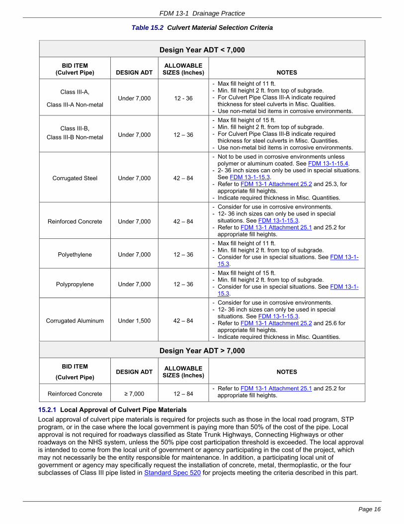
Table 15.2 lists the preferred materials permitted for culvert pipe by traffic volume range.
FDM 13-1 Drainage Practice
Page 16
Table 15.2 Culvert Material Selection Criteria
Design Year ADT < 7,000
BID ITEM (Culvert Pipe) DESIGN ADT
ALLOWABLE SIZES (Inches) NOTES
Class III-A,
Class III-A Non-metal Under 7,000 12 - 36
- Max fill height of 11 ft. - Min. fill height 2 ft. from top of subgrade. - For Culvert Pipe Class III-A indicate required
thickness for steel culverts in Misc. Qualities. - Use non-metal bid items in corrosive environments.
Class III-B,
Class III-B Non-metal Under 7,000 12 – 36
- Max fill height of 15 ft. - Min. fill height 2 ft. from top of subgrade. - For Culvert Pipe Class III-B indicate required
thickness for steel culverts in Misc. Quantities. - Use non-metal bid items in corrosive environments.
Corrugated Steel Under 7,000 42 – 84
- Not to be used in corrosive environments unless polymer or aluminum coated. See FDM 13-1-15.4.
- 2- 36 inch sizes can only be used in special situations. See FDM 13-1-15.3.
- Refer to FDM 13-1 Attachment 25.2 and 25.3, for appropriate fill heights.
- Indicate required thickness in Misc. Quantities.
Reinforced Concrete Under 7,000 42 – 84
- Consider for use in corrosive environments. - 12- 36 inch sizes can only be used in special
situations. See FDM 13-1-15.3. - Refer to FDM 13-1 Attachment 25.1 and 25.2 for
appropriate fill heights.
Polyethylene Under 7,000 12 – 36
- Max fill height of 11 ft. - Min. fill height 2 ft. from top of subgrade. - Consider for use in special situations. See FDM 13-1-
15.3.
Polypropylene Under 7,000 12 – 36
- Max fill height of 15 ft. - Min. fill height 2 ft. from top of subgrade. - Consider for use in special situations. See FDM 13-1-
15.3.
Corrugated Aluminum Under 1,500 42 – 84
- Consider for use in corrosive environments. - 12- 36 inch sizes can only be used in special
situations. See FDM 13-1-15.3. - Refer to FDM 13-1 Attachment 25.2 and 25.6 for
appropriate fill heights. - Indicate required thickness in Misc. Quantities.
Design Year ADT > 7,000
BID ITEM
(Culvert Pipe) DESIGN ADT
ALLOWABLE SIZES (Inches)
NOTES
Reinforced Concrete ≥ 7,000 12 – 84 - Refer to FDM 13-1 Attachment 25.1 and 25.2 for
appropriate fill heights.
15.2.1 Local Approval of Culvert Pipe Materials
Local approval of culvert pipe materials is required for projects such as those in the local road program, STP program, or in the case where the local government is paying more than 50% of the cost of the pipe. Local approval is not required for roadways classified as State Trunk Highways, Connecting Highways or other roadways on the NHS system, unless the 50% pipe cost participation threshold is exceeded. The local approval is intended to come from the local unit of government or agency participating in the cost of the project, which may not necessarily be the entity responsible for maintenance. In addition, a participating local unit of government or agency may specifically request the installation of concrete, metal, thermoplastic, or the four subclasses of Class III pipe listed in Standard Spec 520 for projects meeting the criteria described in this part.
FDM 13-1 Drainage Practice
Page 17
15.3 Special Situations
Special conditions at the proposed culvert site may require that a specific type of pipe be used. Such special conditions include acidity of soils/water or other corrosive conditions, local preference when meeting the conditions described above in FDM 13-1-15.2.1, limited cover (see FDM 13-1-15.6), extending existing culvert pipes, unusual loading from high embankments, steep gradients, or other pertinent reasons.
15.4 Corrosion Concerns About Steel Culvert Pipe
Corrosion of zinc-coated (galvanized) steel pipe results from different mechanisms in different regions of the state. A Wisconsin map outlining the potential areas for bacterial corrosion of zinc galvanized steel culvert pipes is shown on Attachment 15.1. In the north and central part of Wisconsin (Area 1, Figure 15.1), corrosion of steel pipe is due mainly to the activity of anaerobic sulfate reducing bacteria (ASR) in the surface water. This region is characterized by low alkalinity of the surface water. These ASR bacteria do not attack the steel directly but create an environment favorable to corrosion. Corrosion resistant pipe should be specified for use in Area 1 with the exception of commonly dry sites where existing zinc-coated (galvanized) steel pipe have not had a history of corrosion.
In Area 2, zinc-coated (galvanized) steel pipe should be used only at sites where surface water has a minimum alkalinity of 120 milligrams per liter or where existing zinc-coated (galvanized) steel pipe at the site have had an acceptable service history. Metal culvert pipe of any type should provide a minimum service life of 20 years before perforation occurs.
In the remainder of the state (Area 3), corrosion is more commonly related to local conditions such as high electrical conductivity of water and fine grained soil. Other contributing factors would include high or low pH of soil or water and the presence of ASR bacteria in organic, poorly drained soil.
Corrosion resistant pipe may be necessary where drainage originates in bogs, swamps, barnyards or low-lying lands drained by ditches or tile. An acceptable corrosion resistant pipe should be specified in Area 3 when the pH is outside the range of five to nine and the resistivity is below 2000 ohm centimeters, or when the resistivity is below 1000 ohm centimeters regardless of the Ph. Acceptable corrosion resistant pipe materials are concrete, aluminum, aluminized steel, polymer coated steel, polyethylene and polypropylene.
* Note: Inspection of several aluminum drainage structures in 1993 revealed localized corrosion of the top and sides of the center sections of the structures. The corrosion appears to be related to the use of chlorides for snow and ice removal. The use of aluminum pipe should therefore be limited to side drains and highways with traffic volumes under 1500 Design AADT unless some provision is made to insulate the upper surface of the structure from infiltrating road salt.
Information about the corrosive characteristics of the soil or water at a site may already be available from region soils or maintenance records. In some cases it may be necessary to conduct field and laboratory tests to determine whether corrosive conditions exist. The region Soils Engineer can normally advise the designer about the need for such tests and conduct them if needed.
As conditions allow, and with the exceptions listed, Culvert Pipe Class III-A Non-metal, and Culvert Pipe Class III-B Non-metal under Standard Spec 520 are to be specified for culverts in corrosive conditions where ADT is less than 7,000. Reinforced concrete pipe is required for culverts under high volume roadways (ADT>7,000).
15.4.1 Corrosion Concerns For Concrete Pipe
Where existing reinforced concrete pipe has corroded consider specifying thermoplastic pipe under Standard Spec 530 for roadways where ADT is less than 7,000. Where corrosion has occurred in concrete pipes under high volume roadways (ADT>7,000), contact one of the statewide drainage engineers for assistance.
15.4.2 Corrosion Concerns For Steel Endwalls
Where corrosion resistant pipe materials or coatings are specified for a project similar treatment of the endwalls may be necessary. In the case of Culvert Pipe Class III-A and Class III-B items consider the need for a special provision article requiring aluminum apron endwalls meeting the requirements of Standard Spec 525 for corrugated polyethylene, and corrugated polypropylene pipe culvert installations.
15.5 Abrasion Concerns
The thickness of metal pipe should be increased or the pipe invert paved where water velocity combined with a bed load of sand, gravel or stone is likely to cause significant erosion or abrasion of the pipe invert. The existence of abrasive conditions at a proposed culvert site can be determined from inspection of the existing metal pipe at the site or inspection of other pipes in the same general area or on the same watercourse.
FDM 13-1 Drainage Practice
Page 18
15.6 Limited Clearance Installations
When a low clearance pipe is required, the designer may call for any of the following.
- Reinforced concrete elliptical or arch pipe
- Corrugated steel or aluminum pipe arch
- Structural plate pipe arch
- Aluminum structural plate pipe arch.
Arch pipe may also be warranted on the basis of special hydraulic or aquatic organism passage design requirements.
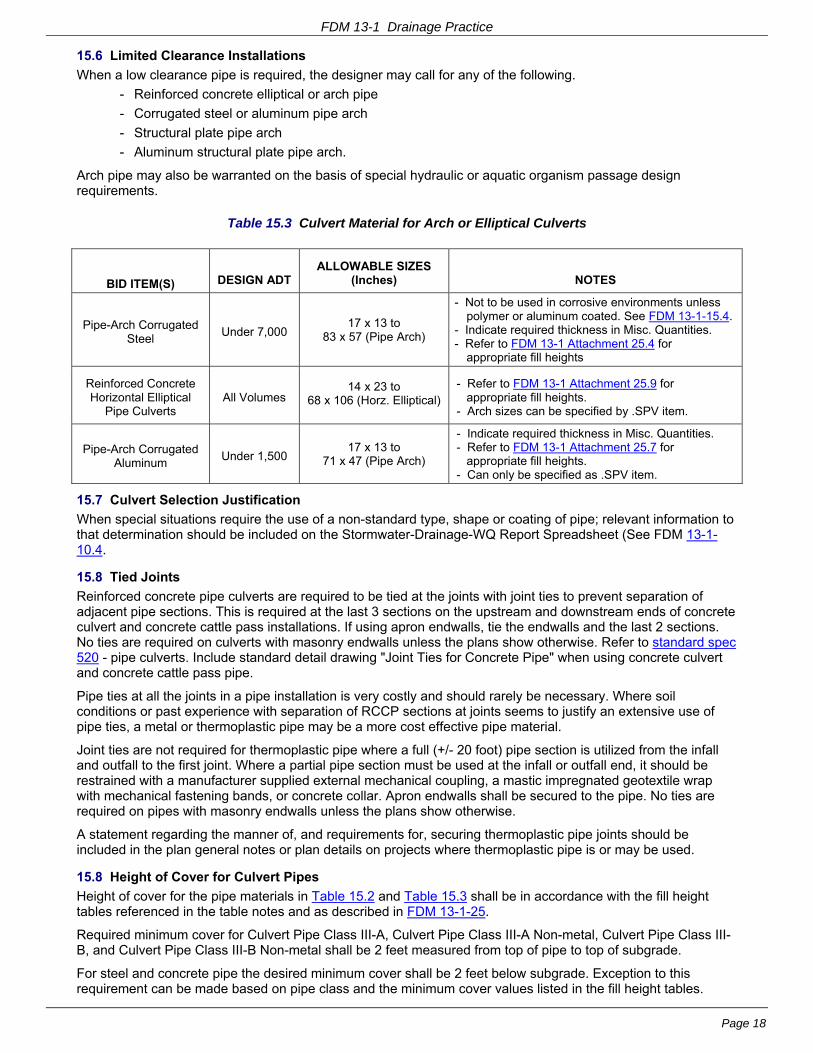
Table 15.3 Culvert Material for Arch or Elliptical Culverts
BID ITEM(S) DESIGN ADT ALLOWABLE SIZES
(Inches) NOTES
Pipe-Arch Corrugated Steel
Under 7,000 17 x 13 to
83 x 57 (Pipe Arch)
- Not to be used in corrosive environments unless polymer or aluminum coated. See FDM 13-1-15.4.
- Indicate required thickness in Misc. Quantities. - Refer to FDM 13-1 Attachment 25.4 for
appropriate fill heights
Reinforced Concrete Horizontal Elliptical
Pipe Culverts All Volumes
14 x 23 to 68 x 106 (Horz. Elliptical)
- Refer to FDM 13-1 Attachment 25.9 for appropriate fill heights.
- Arch sizes can be specified by .SPV item.
Pipe-Arch Corrugated Aluminum
Under 1,500 17 x 13 to
71 x 47 (Pipe Arch)
- Indicate required thickness in Misc. Quantities. - Refer to FDM 13-1 Attachment 25.7 for
appropriate fill heights. - Can only be specified as .SPV item.
15.7 Culvert Selection Justification
When special situations require the use of a non-standard type, shape or coating of pipe; relevant information to that determination should be included on the Stormwater-Drainage-WQ Report Spreadsheet (See FDM 13-1-10.4.
15.8 Tied Joints
Reinforced concrete pipe culverts are required to be tied at the joints with joint ties to prevent separation of adjacent pipe sections. This is required at the last 3 sections on the upstream and downstream ends of concrete culvert and concrete cattle pass installations. If using apron endwalls, tie the endwalls and the last 2 sections. No ties are required on culverts with masonry endwalls unless the plans show otherwise. Refer to standard spec 520 - pipe culverts. Include standard detail drawing "Joint Ties for Concrete Pipe" when using concrete culvert and concrete cattle pass pipe.
Pipe ties at all the joints in a pipe installation is very costly and should rarely be necessary. Where soil conditions or past experience with separation of RCCP sections at joints seems to justify an extensive use of pipe ties, a metal or thermoplastic pipe may be a more cost effective pipe material.
Joint ties are not required for thermoplastic pipe where a full (+/- 20 foot) pipe section is utilized from the infall and outfall to the first joint. Where a partial pipe section must be used at the infall or outfall end, it should be restrained with a manufacturer supplied external mechanical coupling, a mastic impregnated geotextile wrap with mechanical fastening bands, or concrete collar. Apron endwalls shall be secured to the pipe. No ties are required on pipes with masonry endwalls unless the plans show otherwise.
A statement regarding the manner of, and requirements for, securing thermoplastic pipe joints should be included in the plan general notes or plan details on projects where thermoplastic pipe is or may be used.
15.8 Height of Cover for Culvert Pipes
Height of cover for the pipe materials in Table 15.2 and Table 15.3 shall be in accordance with the fill height tables referenced in the table notes and as described in FDM 13-1-25.
Required minimum cover for Culvert Pipe Class III-A, Culvert Pipe Class III-A Non-metal, Culvert Pipe Class III-B, and Culvert Pipe Class III-B Non-metal shall be 2 feet measured from top of pipe to top of subgrade.
For steel and concrete pipe the desired minimum cover shall be 2 feet below subgrade. Exception to this requirement can be made based on pipe class and the minimum cover values listed in the fill height tables.
FDM 13-1 Drainage Practice
Page 19
Where less than two feet of cover is provided special measures may be required during construction to minimize equipment loading impacts on the pipe. At a minimum, locations with reduced subgrade cover should be identified on the plans so that the contractor can take precautionary measures.
LIST OF ATTACHMENTS
Attachment 15.1 Potential for Bacterial Corrosion of Zinc Galvanized Steel Culvert Pipe (Map)
FDM 13-1-17 Storm Sewer Material Selection Standard March 31, 2017
17.1 Purpose
This procedure provides guidelines for the selection of storm sewer materials.
Standard Spec 608 - Storm Sewer, categorizes storm sewer pipe strengths by class, ranging from Class II with a maximum allowable fill height of 11 feet for reinforced concrete to Class V with a maximum fill height of 35 feet.
Selection of pipe materials is to be based on traffic volume and fill height with consideration given to special situations or site conditions as described in FDM 13-1-17.3 to FDM 13-1-17.5.
Similarly to culverts, beginning with the 2016 Standard Specifications, two new series of bid items were added to Section 608 Storm Sewer; Storm Sewer Pipe Class III-A, and Storm Sewer Pipe Class III-B. These Class III-A and Class-III B bid items allow the contractor to choose from multiple pipe materials including thermoplastic pipe (corrugated polyethylene and corrugated polypropylene) for sizes up to 36 inches in diameter. Previously, thermoplastic pipe could only be specified via STSP. As described in FDM 13-1-17.3.1, the intent of these Class III-A and Class-III B items is to introduce potential project cost reductions into the competitive bid process by allowing the contractor to select from multiple material options for pipes sized up to 36 inches.
Within Class III for Storm Sewer there are two subclasses.
- Class III-A
- includes Class II and Class III reinforced concrete, corrugated polyethylene, and corrugated polypropylene.
- Class III-A has a maximum fill height of 11 ft.
- Class III-B
- includes Class III reinforced concrete and corrugated polypropylene
- Class III-B has a maximum fill height of 15 ft.
17.2 Background
The following factors influence the selection of materials for storm sewers:
flow characteristics life expectancy
physical strength resistance to corrosion
ease of handling and installation availability
Concrete pipe satisfies nearly all of these factors and therefore has been the traditional storm sewer pipe material specified by the department.
Table 17.1 lists the preferred materials permitted for storm sewer pipe by traffic volume range. As conditions allow, and with the exceptions listed, Storm Sewer Pipe Class III-A, and Storm Sewer Pipe Class III-B under Standard Spec 608 shall be specified for storm sewers where ADT is less than 7,000.
Reinforced concrete pipe is required for storm sewers under high volume roadways (ADT>7,000) although some exceptions are allowed as described in FDM 13-1-17.3.1.
Once it has been determined which storm sewer materials are suitable for a specific project or site, it may be required to get the approval of affected local government officials prior to developing final plans and specifications. FDM 13-1-17.3.2 describes when local approval is required for projects.
17.3 Approved Materials
The materials shown in Table 17.1 below may be used with the following restrictions.
FDM 13-1 Drainage Practice
Page 20
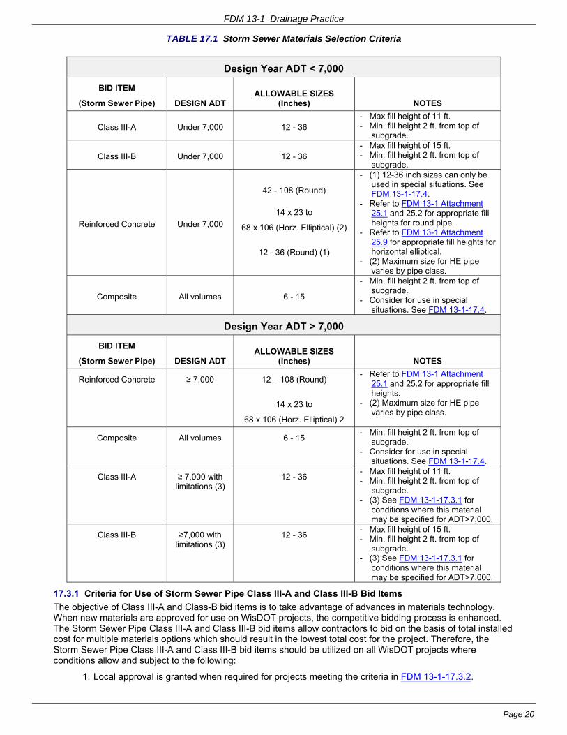
TABLE 17.1 Storm Sewer Materials Selection Criteria
Design Year ADT < 7,000
BID ITEM
(Storm Sewer Pipe) DESIGN ADT ALLOWABLE SIZES
(Inches) NOTES
Class III-A Under 7,000 12 - 36 - Max fill height of 11 ft. - Min. fill height 2 ft. from top of
subgrade.
Class III-B Under 7,000 12 - 36 - Max fill height of 15 ft. - Min. fill height 2 ft. from top of
subgrade.
Reinforced Concrete Under 7,000
42 - 108 (Round)
14 x 23 to
68 x 106 (Horz. Elliptical) (2)
12 - 36 (Round) (1)
- (1) 12-36 inch sizes can only be used in special situations. See FDM 13-1-17.4.
- Refer to FDM 13-1 Attachment 25.1 and 25.2 for appropriate fill heights for round pipe.
- Refer to FDM 13-1 Attachment 25.9 for appropriate fill heights for horizontal elliptical.
- (2) Maximum size for HE pipe varies by pipe class.
Composite All volumes 6 - 15
- Min. fill height 2 ft. from top of subgrade.
- Consider for use in special situations. See FDM 13-1-17.4.
Design Year ADT > 7,000
BID ITEM
(Storm Sewer Pipe) DESIGN ADT ALLOWABLE SIZES
(Inches) NOTES
Reinforced Concrete ≥ 7,000 12 – 108 (Round)
14 x 23 to
68 x 106 (Horz. Elliptical) 2
- Refer to FDM 13-1 Attachment 25.1 and 25.2 for appropriate fill heights.
- (2) Maximum size for HE pipe varies by pipe class.
Composite All volumes 6 - 15 - Min. fill height 2 ft. from top of
subgrade. - Consider for use in special
situations. See FDM 13-1-17.4.
Class III-A ≥ 7,000 with limitations (3)
12 - 36 - Max fill height of 11 ft. - Min. fill height 2 ft. from top of
subgrade. - (3) See FDM 13-1-17.3.1 for
conditions where this material may be specified for ADT>7,000.
Class III-B ≥7,000 with limitations (3)
12 - 36 - Max fill height of 15 ft. - Min. fill height 2 ft. from top of
subgrade. - (3) See FDM 13-1-17.3.1 for
conditions where this material may be specified for ADT>7,000.
17.3.1 Criteria for Use of Storm Sewer Pipe Class III-A and Class III-B Bid Items
The objective of Class III-A and Class-B bid items is to take advantage of advances in materials technology. When new materials are approved for use on WisDOT projects, the competitive bidding process is enhanced. The Storm Sewer Pipe Class III-A and Class III-B bid items allow contractors to bid on the basis of total installed cost for multiple materials options which should result in the lowest total cost for the project. Therefore, the Storm Sewer Pipe Class III-A and Class III-B bid items should be utilized on all WisDOT projects where conditions allow and subject to the following:
1. Local approval is granted when required for projects meeting the criteria in FDM 13-1-17.3.2.
FDM 13-1 Drainage Practice
Page 21
2. The diameter of the pipe may not exceed 36 inches.
3. One or more of the following conditions exists:
- Where design year traffic volume does not exceed 7000 ADT, unless a special situation as defined in FDM 13-1-17.4 applies.
- Where the design year traffic volume is equal to or exceeds 7000 AADT. Storm Sewer Pipe Class III-A and Class III-B bid items may be specified for storm sewer located outside of traffic lanes such as the following locations:
- Behind curb and gutter.
- Under parking lanes where future use of the lane for through traffic is not expected.
- Outside the limits of the roadway such as for infall and outfall pipes.
- Lower volume sideroads when outside the mainline traffic lanes.
4. Storm Sewer Pipe Class III-A and Class III-B is not allowed in areas such as expressway or freeway medians. Future expansion of these facilities could unintentionally place the pipe under traffic lanes.
Exceptions to these conditions may be granted at locations determined in cooperation with the Bureau of Technical Services and Roadway Design Standards Unit for the purpose of gaining additional experience with the materials in a variety of traffic volume and site conditions.
While the use of Class III-A and Class III-B bid items whenever possible is desired, some discretion is left to the designer on high volume (>7,000 ADT) roadways. Designers are not expected, for example, to change materials back and forth between manholes, or call out a few individual short runs of Class III-A or B pipe. In addition, there may be situations where the selection of a specific material is justified such as specifying concrete pipe or thermoplastic pipe to match an existing pipe material.
WisDOT takes a conservative approach to the implementation of the use of new materials such as thermoplastic pipe. However, thermoplastic pipe is not an entirely new material to the Department as it has been utilized throughout the state for many years without significant issues in advance of the development current standards. Continued monitoring of the performance of these materials in the field will take place, and standards will be adjusted as necessary.
17.3.2 Local Approval of Storm Sewer Materials
Local approval of storm sewer materials is required for projects such as those in the local road program, STP program, or in the case where the local government is paying more than 50% of the cost of the pipe. Local approval is not required for roadways classified as State Trunk Highways, Connecting Highways or roadways otherwise on the NHS system, unless the 50% pipe cost participation threshold is exceeded. The local approval is intended to come from the local unit of government or agency participating in the cost of the project, which may not necessarily be the entity responsible for maintenance. In addition, a participating local unit of government or agency may specifically request the installation of concrete, thermoplastic, Storm Sewer Pipe Class III-A or Storm Sewer Pipe Class III-B for projects meeting the criteria described in this part.
17.4 Special Situations
Special conditions at the proposed storm sewer site may require that a specific type of pipe be used. Such special conditions include; local preference when meeting the conditions described in FDM 13-1-17.3.2, limited cover, extending existing storm sewer, unusual loading from high embankments, steep gradients, or other pertinent reasons. Additional special situations where a particular pipe material, such as composite pipe, may be desirable include storm water control BMP’s outside of traffic areas, very short pipe runs between adjacent inlets or where a pipe less than 12 inches in diameter is required.
17.5 High Groundwater and Buoyancy of Thermoplastic Pipe
All pipe materials, including concrete, are subject to buoyant forces and floatation in saturated conditions. Buoyancy is of particular concern for thermoplastic pipe due to its light weight. When covered even with minimal roadway pavement, floatation of thermoplastic pipe is not a significant concern. For installations outside the pavement structure, however, high groundwater can be a concern. Examples of this condition are storm sewer running in a median, ditchline, terrace, or other “soil only” area of cover.
Where high groundwater and fully saturated soil conditions are anticipated, the minimum cover for storm sewer outside the roadway shall be 48 inches for thermoplastic pipe, otherwise reinforced concrete pipe should be specified. For locations where stormsewer is under the roadway pavements, the required minimum 2 foot subgrade cover specified in the FDM is sufficient. Additional depth of cover may be necessary if backfill materials other than the standard foundation and trench backfill materials described in Standard Spec 608 are employed.
FDM 13-1 Drainage Practice
Page 22
The risk of high groundwater conditions can be found from soil boring data such as depth to groundwater or soil morphology. Other resources include; soil mapping (presence of hydric soils), standing water, historic aerial photography, presence of dry weather infiltration in existing storm sewer systems, local well drilling records, USGS data, wetland mapping, field review, and local knowledge.
17.6 Storm Sewer Pipe Connections
17.6.1 Storm Sewer Joints
Standard Spec 608 lists several acceptable joint types for the range of allowable storm sewer materials. In general these joints are intended to be soil tight. Standard spec 608 does not specifically require joints to be watertight at this time.
Watertight joints are required however in areas of contaminated groundwater and/or soil and may be necessary in areas of high groundwater. In these cases a special provision article will be necessary to specify watertight joints. Often the AASHTO or ASTM material designations referenced in standard spec 608 contain standards for watertight joints and should be reviewed for applicability to the project conditions. Applicable sections of the LRFD Bridge Construction Specifications also reference requirements for watertight joints and can be referenced.
17.6.2 Tied Joints
In certain circumstances concrete pipe storm sewers are required to be tied at the joints with joint ties to prevent separation of adjacent pipe sections. This is required at the last 3 sections of the system infalls and outfalls. If using apron endwalls, tie the endwall and the last 2 sections. No ties are required on storm sewers with masonry endwalls unless the plans show otherwise (refer to Standard Spec 608 - Storm Sewers). Include standard detail drawings "Joint Ties of Concrete Pipes" when using concrete pipe storm sewers with infalls or outfalls.
Pipe ties at all the joints in a pipe installation is very costly and should rarely be necessary. Where soil conditions or past experience with separation of RCP sections at joints seems to justify an extensive use of pipe ties, the use of thermoplastic pipe materials may be more cost effective.
Joint ties are not required for thermoplastic pipe where a full (+/- 20 foot) pipe section is utilized from the infall and outfall to the first joint. Where a partial pipe section must be used at the infall or outfall end, it should be restrained with a manufacturer supplied external mechanical coupling, a mastic impregnated geotextile wrap with mechanical fastening bands, or a concrete collar. Apron endwalls shall be secured to the pipe. No ties are required on pipes with masonry endwalls unless the plans show otherwise.
A statement regarding the manner of, and requirements for, securing thermoplastic pipe joints should be included in the plan general notes or plan details on projects where thermoplastic pipe is or may be used.
17.6.3 Connections at Structures
At this time WisDOT Standard Specifications and standard detail drawings do not require watertight connections for storm sewer at catch basins, manholes and inlets. Mortared connections between the structure and sewer pipe are required. In areas of groundwater and/or soil contamination or areas otherwise designated as requiring watertight joints, a special provision will be necessary. In preparing a special provision article to address groundwater infiltration into a structure, consider the need for additional waterproofing at joints between structure sections and for joints at risers and castings. A cautious approach should be used when specifying the manner of waterproof connection between the sewer pipe and structure. On projects where multiple material types can be allowed (i.e. Storm Sewer Pipe Class III-A and Class III-B) constructability issues could arise if a specific, or proprietary manner of connection is specified.
17.7 Height of Cover for Storm Sewer
Height of cover for the pipe materials in Table 17.1 shall be in accordance with the fill height tables referenced in the table notes and as described in FDM 13-1-25.
Minimum cover for Storm Sewer Pipe Class III-A, Storm Sewer Class III-B and composite pipe shall be 2 feet measured from top of pipe to top of subgrade where the pipe is under pavement. Additional cover is required when high groundwater may be encountered per FDM 13-1-17.5.
For concrete pipe the desired minimum cover shall be 2 feet below subgrade. Exception to this requirement can be made based on pipe class and the minimum cover values listed in the fill height tables.
Where less than two feet of cover is provided special measures may be required during construction to minimize equipment loading impacts on the pipe. At a minimum, locations with reduced subgrade cover should be identified on the plans so that the contractor can take precautionary measures.
FDM 13-1 Drainage Practice
Page 23
17.7 Roughness Coefficient
A constant coefficient of roughness value of 0.013 should be used in the Manning Formula for all of the storm sewer materials described in this procedure.
FDM 13-1-20 Large Drainage Conduit December 18, 2015
20.1 Introduction
Large drainage conduit is defined in general as conduit larger than 84 inches in equivalent diameter, which equates in cross-sectional area to 38.5 square feet. This size was selected because it is near the top of the range of sizes at which pipe can be factory assembled while still being a practical size for transporting.
The types of large conduit available include structural plate pipe and structural plate pipe arch (AASHTO m167), aluminum alloy structural plate pipe and pipe arch (AASHTO m219), steel pipe with 3" x 1" corrugations (AASHTO m36), reinforced concrete pipe (AASHTO m170), reinforced concrete arch pipe (AASHTO m206), reinforced concrete elliptical pipe (AASHTO m207), and cast-in-place or precast box culverts (AASHTO m259).
The selection of a specific type of large conduit should be made on the basis of economics unless other considerations dictate the need for a particular type of large conduit. Other factors that should be considered include the availability of the conduit in the area of the project; foundation conditions at the project site; time available for construction, including consideration of how traffic will be handled; and the existence of corrosive or abrasive conditions at the site. Special hydraulic requirements, aquatic organism passage, or limited clearance conditions may require the use of a corrugated steel pipe arch, structural plate pipe arch, or wide box culvert.
Two or more conduit types may be specified as equal alternates when either type will satisfy design requirements. For example, aluminum structural plate pipe arch and (steel) structural plate pipe arch could be specified as equal alternates.
Multiple lines of pipe culverts or pipe arches may also be a feasible alternative to large drainage conduit.
FDM 13-1-21 Precast Box Culverts December 18, 2015
21.1 Introduction
Precast box culverts are one of the large drainage conduit alternatives the designer may choose to resolve a given drainage problem. The choice of this option should be based on the criteria given in FDM 13-1-20 as well as sound engineering judgment. One factor that must be considered is earth cover. Fill height criteria for similarly sized cast-in-place culverts may be used, except precast box culverts may be used only in those situations which provide for at least two feet of earth cover under the traffic areas.
The broad range of sizes offers the designer many choices when studies indicate large drainage conduit is suitable. Multiple cell installations are permitted.
When determining whether a box culvert should be precast or cast-in-place, an analysis should be conducted to compare the options. This analysis should attempt to identify all the factors involved, including costs, many of which are not readily apparent.
Generally, initial cost of a cast in place box is less expensive than a precast box culvert. However, precast box culvert installation can be completed in a much shorter time than a cast-in-place option. This is especially of value where a detour is not feasible, and a short-term closure can be allowed. Precast box culverts may be used in emergency situations. In situations where complete closure is impossible, precast units can be used in a bypass, and then left in place or reset to a new position. Some local roads can carry detour traffic for short durations, but cannot sustain long-term use without costly maintenance and repair. Road user costs, such as delays due to indirection, may be a factor. Grading projects may realize a cost advantage by providing early access to an entire project, expediting movement of embankment materials and other construction operations. The minimum time and amount of disruption to streams is an easily identified positive environmental aspect.
Quality control of materials and curing conditions is an advantage to casting the units in a plant environment. The dry mix used in the units yields a denser, less permeable concrete than the cast-in-place option.
End treatments may be precast, cast-in-place, or a combination of both.
If a precast box culvert is selected for a particular design project, the designer shall notify the Bureau of Structures (BOS) early in scoping or design phase. If project is designed by a consultant, preliminary plans and complete final structure plans are required to be sent to BOS for approval. Please refer to 36.12 of the Bridge Manual (http://wisconsindot.gov/Pages/doing-bus/eng-consultants/cnslt-rsrces/strct/bridge-manual.aspx).
FDM 13-1 Drainage Practice
Page 24
FDM 13-1-25 Fill Height Tables December 18, 2015
25.1 Design Criteria
The fill height tables included in this procedure are based on the following design criteria:
1. Weight of Embankment: 120 lbs/ft3
2. Backfill: Good side fill material compacted to 90 percent of standard density based on AASHTO T 99. Modulus of passive soil resistance, E' = 1050 psi. Soil stiffness coefficient, K = 0.33.
3. Bedding: Class C, in accordance with the requirements of the Standard Specifications. The only exception to this bedding requirement is shown in Fill Height Table (Attachment 25.3), where a Class B bedding is required for reinforced concrete pipe placed under fill heights in excess of 35 ft (see Attachment 25.2). Load factors for the zero projecting embankment condition were used in the fill height determinations.
For pipe arch structures, the confining backfill must be capable of supporting a corner pressure of two tons per square foot.
4. Safety factors: 4 for longitudinal seams; 2 for buckling.
5. Materials and fabrication: In accordance with the appropriate AASHTO specification as required by the Standard Specifications or special provisions.
25.2 Design Methods
The fill height tables for flexible conduit were developed using the service load design method described in the AASHTO LRFD Bridge Design Specifications. The fill height table for reinforced concrete pipe was developed using the design procedure included in the Concrete Pipe Design Manual prepared by the American Concrete Pipe Association.
25.3 Cut Ends
The ends of metal pipe cut as skews or mitered to slope (or both) are not as strong as square ends. Cut ends should be reinforced with concrete headwalls or collars when the bevel is flatter than 2:1 and the skew is greater than 20 degrees.
25.4 Multiple Structures
Where multiple lines of pipes or pipe arches greater than 48 inches in diameter or span are used, they shall be spaced so that the adjacent sides of the pipe are at least one-half diameter or three feet apart, whichever is less, to permit adequate compaction of backfill material. For diameters up to 48 inches the minimum spacing shall be 24 inches.
When multiple lines of pipe have less than half the diameter of the smallest pipe between them and the out-to-out length along the roadway reference line is greater than 20 feet, the pipe installation shall be assigned a B-number by the Region. Coordination with the Bureau of Structures is required in these situations.
25.5 Abrasive or Corrosive Conditions
Metal thicknesses shown in the fill height tables are adequate for structural requirements only. Where corrosive and/or abrasive conditions exist, either greater thicknesses or protective coatings should be provided. For structural plate pipe, greater thicknesses may be specified for the plates in the invert.
LIST OF ATTACHMENTS
Attachment 25.1 Storm Sewer Fill Height Table for Concrete Pipe
Attachment 25.2 Fill Height Table - Corrugated Steel, Aluminum, Polyethylene, Polypropylene and Reinforced Concrete Pipe, HS20 Loading, 2" x 2/3" Corrugations
Attachment 25.3 Fill Height Tables: Corrugated Steel Pipe, 3in x 1in Corrugations; and Structural Plate Pipe, 6in x 2in Corrugations
Attachment 25.4 Fill Height Tables: Corrugated Steel Pipe Arch, 2- 2/3in x 1/2in Corrugations; and Corrugated Steel Pipe Arch, 3in x 1in Corrugations
Attachment 25.5 Fill Height Table, Structural Plate Pipe Arch, 6inx2in Corrugations
Attachment 25.6 Fill Height Tables: Corrugated Aluminum Pipe, 3in x 1in Corrugations; and Aluminum Alloy Structural Plate Pipe, 9in x 2 1/2in Corrugations
FDM 13-1 Drainage Practice
Page 25
Attachment 25.7 Fill Height Table, Corrugated Aluminum Pipe Arch, 2 2/3in x 1/2in Corrugations
Attachment 25.8 Fill Height Table, Aluminum Alloy Structural Plate Pipe Arch, 9in x 2- 1/2in Corrugations
Attachment 25.9 Fill Height Table, Reinforced Concrete Arch and Elliptical Pipe (all sizes); and Dimensions for Reinforced Concrete Arch and Elliptical Pipe (English)