Embed Size (px)
Citation preview
fDEPARTMENT OF DEFENCE
DEFENCE SCIENCE & TECHNOLOGY ORGANISATION DSTO
Wing in Ground Effect Craft Review
Michael Halloran and Sean O'Meara
DSTO-GD-0201
Wing in Ground Effect Craft Review
Michael Halloran and Sean O'Meara
The Sir Lawrence Wackett Centre pr Aerospace Design Technology Royal Melbourne Institute of Technology
Contract Report CR-9802
Study sponsored by Maritime Platforms Division
Aeronautical and Maritime Research Laboratory
DSTO-GD-0201
ABSTRACT
It has long been recognised that flight close to a boundary surface is more aerodynamically efficient than flight in the freestream. This has led to the design and construction of craft specifically intended to operate close to the ground and fly 'in ground effect'. A great range of Wing in Ground effect craft (WIGs) have been manufactured ranging from 2 seat recreational vehicles to 500 tonne warcraft. Despite this WIGs have never enjoyed great commercial or military success.
The Maritime Platform Division of DSTO commissioned The Sir Lawrence Wackett Centre for Aerospace Design Technology to conduct a design review of WIG craft. This review considers all elements of WIG design and operation, including performance, limitations, control, stability, operational requirements, regulation, manufacture and technological risk. The review highlights the research required to overcome the weaknesses of WIG craft, the advantages that they may offer and the possible uses of WIG craft in the Australian military.
RELEASE LIMITATION
Approved for public release
DEPARTMENT OF DEFENCE
DEFENCE SCIENCE & TECHNOLOGY ORGANISATION DSTO oncQUALrnriNSPBcwDi 1 9990 4J502Q

Published by
DSTO Aeronautical and Maritime Research Laboratory PO Box 4331 Melbourne Victoria 3001 Australia
Telephone: (03) 9626 7000 Fax: (03)9626 7999 © Commonwealth of Australia 1999 AR-010-831 February 1999
APPROVED FOR PUBLIC RELEASE
Wing in Ground Effect Craft Review
Executive Summary
The Royal Australian Navy (RAN) is investigating the development of high speed craft to meet the Australian defence needs of the coming century. The Maritime Platform Division of the Aeronautical and Maritime Research Laboratory, DSTO has been tasked with the investigation of various high speed craft. As a part of this investigation, The Sir Lawrence Wackett Centre for Aerospace Design Technology, RMIT has been tasked with the provision of this report addressing the current state of wing in ground effect craft. This report provides the theory of the efficiency of wings operating in ground effect and the historical background to the development of WIG craft. The report also attempts to outline the performance characteristics of WIG craft and the operational limitations that might be found on developed WIG craft. A quantity of experimental and operational data is also provided, although little independent data is available for full sized operational craft. Practical applications of WIG craft have been actively researched and developed since the early 1960's, yet in that period these craft have not reached acceptance as mainstream transport vehicles in either civilian or military applications. No single reason for this failure to develop is obvious. While there are some technical difficulties to overcome, none of these appears insurmountable and while there are some operational limitations, they are not so severe that these craft could not find useful operational niches. WIG craft have been championed on the basis that they are more efficient than equivalent aircraft and quicker than equivalent marine vessels. The efficiency argument is somewhat speculative. While theoretically an improvement in efficiency is gained by flying in ground effect, this efficiency is reduced by design compromises required of the WIG craft. Such compromises include strengthened hull structures, reduced aspect ratios and larger control forces. The degree to which total efficiency is improved can only be determined by the direct comparison of optimised designs of equivalent WIG and aircraft. Only through such a comparison would the value of the improved efficiency and the cost of gaining this efficiency be determined. The speed advantage of WIG craft over conventional marine vessels may well provide the reason for considering WIG craft for particular applications. WIG craft can be developed to travel at significantly faster speeds than the equivalent marine vessels. There may well be applications for marine vessels where the speed of the vessel is the most critical specification. The limitations of the vehicle are primarily concerned with sea state. Landing and take off of WIG craft is limited to relatively small sea states and cruise over high sea states, while possible, is relatively inefficient. Other disadvantages are primarily concerned with the operation of aircraft structures in marine environments. Along with the use of exposed engines, corrosion on load bearing light weight structures will demand a relatively high maintenance cost.
Stability and control, aerodynamics analysis and systems are all areas that have provided difficulties to the designers of WIG craft. These difficulties have been overcome by recent developments in the aviation field. It is also considered that the technology available in these fields is more than adequate for use on WIG craft. Research into take off aids has the potential to reduce the sea state limitations on WIG craft. This area of research is likely to provide the most important contributions to the reduction of these limitations. Other areas in which further research is required are propulsion, hull load determination and sensors. The use of exposed engines in the highly corrosive marine environment carries a high maintenance cost and reduced reliability. The accurate determination of hull loads in the takeoff and landing phases would lead to more efficient structural design. Increased safety and better cruise performance may well flow from accurate sensors detecting sea state, altitude and obstacles. This research would primarily involve the adaptation of current technology to the special requirements of WIG craft. There are no apparent technological barriers to the successful design, manufacture and operation of WIG craft.

Table of Contents
INTRODUCTION 1
THEORY 2
2.1 THEORY OF FLIGHT 2
2.1.1 Lift and Drag 2
2.1.2 Downwash 4
2.1.3 Geometry 4
2.2 GROUND EFFECT 5
2.2.1 Lift, Drag and Downwash 5 2.3 PITCHING MOMENT 7
2.3.1 Maximum Lift * 2.3.2 Effect of Height above the Ground 8 2.3.3 Effect on Different Types of Wing Sections and Wing Planforms 10
2.4 THEORETICAL BENEFITS OF GROUND EFFECT 1l 2.4.1 Efficiency Benefits Compared to Aircraft 11 2.4.2 Comparison to Water Borne Craft 12
2.5 STABILITY AND CONTROL IN GROUND EFFECT 13 2.5.1 Height Stability I3
2.5.2 Pitch Stability ]3
2.5.3 Directional Control and Manoeuvrability 14 2.5.4 Speed Stability 14
HISTORICAL PERSPECTIVE 16
3.1 HISTORY TO DATE 16
3.1.1 WIG Craft Terminology I9
3.1.2 Types of WIG Craft 19 3.2 PRODUCTION WIG CRAFT 23
3.2.1 Orlyonok 23
3.2.2 Lun 25
3.2.3 Other WIG Craft 25 3.3 CURRENT TECHNOLOGY AND RESEARCH 28
DESIGN 30
4.1 DESIGN PHILOSOPHIES 30
4.2 PERFORMANCE 32
4.2.1 Design Parameters: Air Borne Performance 32 4.2.2 Design Parameters: Seaborne Performance 35 4.2.3 Design Parameters: Sea and Air Performance 38
4.3 PRODUCTION WIG CRAFT PERFORMANCE 40 4.3.1 Transport Efficiency 40 4.3.2 Range and Payload. 41 4.3.3 Sea State 43 4.3.4 Cruise Performance 44
4.4 LIMITATIONS 45
4.4.1 Sea State 45 4.4.2 Stability and Control 46 4.4.3 OGE Operation 47 4.4.4 Speed. 47 4.4.5 Propulsion 50
4.5 REGULATION 51
4.5.1 Design and Construction of a New WIG 51 4.5.2 Design Standards 51

4.5.3 Certification Requirements 52
5 OPERATION 54
5.1 ENVELOPE 54
5.2 CURRENT ENVIRONMENTS 55
5.3 POSSIBLE MISSIONS PROFILES 55
5.4 CREW REQUIREMENTS 56 5.4.1 Crew Training Requirements 56 5.4.2 Crew Facilities 56
5.5 SEA PORT REQUIREMENTS 57 5.6 MAINTENANCE REQUIREMENTS 57
5.6.1 Maintenance Cycles 57
6 MANUFACTURE 58
6.1 MANUFACTURING REQUIREMENTS 59 6.2 CONSTRUCTION TIME 59 6.3 POTENTIAL AND CURRENT MANUFACTURES 59
7 TECHNOLOGICAL RISK 60
7.1 TAKE OFF AIDS 61
7.2 PROPULSION 63
7.3 STRUCTURES 64
7.4 SYSTEMS 65
7.4.1 Sensors and Navigation ^ 7.4.2 Actuators 65
7.4.3 Simulation and Modelling *>5 7.5 DEVELOPMENT 66
7.5.1 Configuration Design ^ 7.5.2 Flight Testing 66
8 COSTS 6T
8.1 ACQUISITION 67
8.1.1 Design 67
8.1.2 Manufacture • 6S
8.1.3 Certification Costs 68
8.1.4 Systems 68
8.2 OPERATIONAL 69
8.3 ONGOING RESEARCH AND DEVELOPMENT 69
9 CONCLUSION 70
10 BIBLIOGRAPHY 72
11 GLOSSARY AND ABBREVIATIONS 75

Table of Figures
FIGURE 1 LIFT AND DRAG OF A WING SECTION. 3 FIGURE 2 AERODYNAMIC RELATIONS FOR LIFT AND DRAG OF A TYPICAL WING 3 FIGURE 3 WING IN GROUND EFFECT. 5
FIGURE 4 FLOW FIELD IN AND OUT OF GROUND EFFECT 5 FIGURE 5 SURFACE PRESSURE DISTRIBUTION IN AND OUT OF GROUND EFFECT 7 FIGURE 6 LIFTTO DRAG RATIO VERSUS HEIGHT ABOVE THE BOUNDARY [7] 9 FIGURE 7 PITCHING MOMENT VERSUS LIFT FOR VARIOUS HEIGHTS ABOVE THE BOUNDARY[7] 10 FIGURE 8 THEEKRANOPLANTHELUN 20
FIGURE 9 THE LIPPISCHX-l 14 21
FIGURE 10 TANDEM WING CRAFTBY JORG 22
FIGURE 11 THEORLYONOK 24
FIGURE 12 THREE VIEW OF X-l 14 [10] 34 FIGURE 13 ORLYONOKINDRYDOCK. 38 FIGURE 14 TRANSPORTEFFICIENCY[30] 40 FIGURE 15 FUEL CONSUMPTION [24] 41 FIGURE 16 RANGE AND SPEED OF WIG CRAFT [25] 42 FIGURE 17 PAYLOAD FRACTION VERSUSSPEED [24] 42 FIGURE 18 PAYLOAD FOR VARIOUS SIZE WIG CRAFT. 43 FIGURE 19 WAVE STATE AND SEA CRAFT [21] 43 FIGURE 20 CRUISE SPEED VERSUS WIG CRAFT WEIGHT. 44 FIGURE 21 SEA STATE AT TAKE OFF FOR VARIOUS WIG CRAFT 45 FIGURE 22 VELOCITY VERSUS DRAG DURING TAKE OFF [20] ■ 48 FIGURE 23 INSTALLED POWER FOR VARIOUS WIG CRAFT. 48 FIGURE24 ESTIMATED COST OF DEVELOPMENT AND DESIGN OF A WIG CRAFT. 67
Table of Tables
TABLE 1 WIG SYNONYMS 19
TABLE 2 ORLYONOK TECHNICAL DATA 24
TABLE 3 LUN TECHNICAL DATA 25
TABLE 4 PROTOTYPED AND PRODUCED WIG CRAFT. 26 TABLE 5 TECHNOLOGICAL RESEARCH AREAS: TAKE OFF AIDS 62 TABLE 6 COST OF TAKE OFF RESEARCH 69
DSTO-GD-0201
1 INTRODUCTION
The Royal Australian Navy (RAN) is investigating the development of high speed craft to meet the Australian defence needs of the coming century. The Maritime Platform Division of the Aeronautical and Maritime Research Laboratory, DSTO has been tasked with the investigation of various high speed craft.
As a part of this investigation, The Sir Lawrence Wackett Centre for Aerospace Design Technology, RMIT has been tasked with the provision of this report addressing the current state of wing in ground effect craft.
This report provides the theory of the efficiency of wings operating in ground effect and the historical background to the development of WIG craft. With this background, it goes on to explore the likely technological hurdles remaining in the development of these craft. It also attempts to outline those areas of technology where relevant advances have been made since the major development period of these craft through the 1960's and 1970's.
The report also attempts to outline the performance characteristics of WIG craft and the operational limitations that might be found on developed WIG craft.
A quantity of experimental and operational data is also provided. This data has been gained primarily from the manufacturers and other supporters of WIG craft and comes primarily from experimental and prototype craft. Little independent data is available for full sized operational craft.
Design, regulation, manufacturing requirements and costs are discussed.
The authors wish to acknowledge the gracious gift of time by Mr Laurence Mayer, Senior Naval Architect, AMSA and Mr Chris Holloway a designer and developer of WIG craft. The oversight of this project by Mr Kevin Gaylor of MPD is also appreciated.
DSTO-GD-0201
2 THEORY
Objects that produce lift in moving air are known as lifting bodies. Whilst many different shaped bodies can produce lift, the most efficient so far discovered is the wing. The efficiency of a lifting body is determined by the lift to drag ratio (L/D) of the body. The body that produces the greatest lift for the least drag is the most efficient.
The conventional practical use of lifting bodies, are wings on aircraft. In very broad terms, aircraft fly because the movement of the wing through the air produces a greater static pressure on the lower surface of the wing than on the upper surface of the wing. The pressure differential equates to a resultant force upward which supports the weight of the aircraft. Aircraft normally fly in a freestream, that is the air around the wing is not bounded in any way.
WIG craft make use of a phenomenon known as 'ground effect'. Ground effect is the common name for the phenomenon where a boundary is placed below (and near) the lower surface of the wing. This results in an effective increase in the static pressure below the wing and increases the lift to drag ratio. In practice, the boundary is the earth's surface, whether it is terrain or water.
These effects are only observed when the wing is in close proximity to the boundary. As well as increased efficiency, other aerodynamic characteristics such as control and stability are affected. Therefore, in theory, a WIG craft is more efficient than an aircraft of comparable size.
A considerable body of research work has been devoted to WIG craft and the theory is reasonably well understood. There is however, limited empirical information to support the theory and to indicate particular areas that require ongoing research into the practical uses of WIG craft.
2.1 Theory of Flight
2.1.1 Lift and Drag
The lift and drag produced by a wing define the performance and general attributes of the craft that it supports. A wing moving through the air produces a resultant force. Lift is defined as the component of the resultant force perpendicular to the velocity vector of the wing. Induced drag is defined as the component of the resultant force parallel to the velocity vector of the wing. There are also other forms of drag, which are collectively referred to as parasite or profile drag, which is the drag created by the friction of the object moving through the air. The total drag of an object moving through the air is the sum of induced drag and parasite drag.
Both lift and drag are functions of a number of variables, the density of the air, the velocity of the object through the air and the geometry of the object.
DSTO-GD-0201
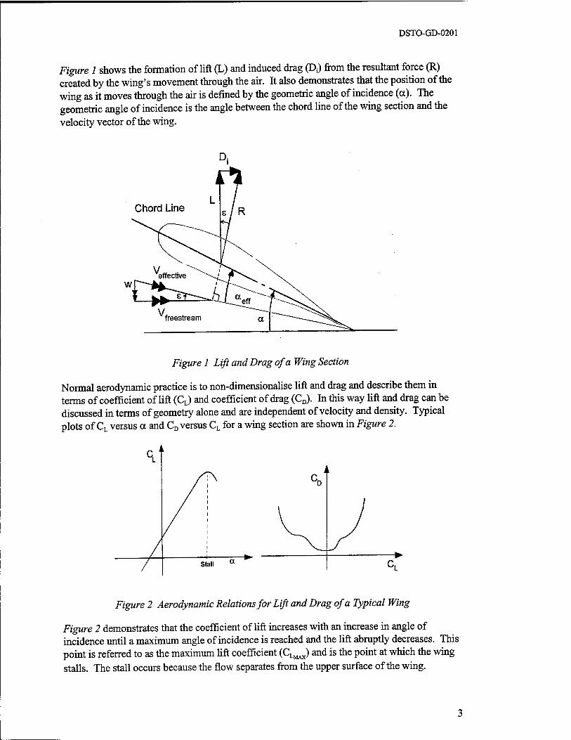
Figure 1 shows the formation of lift (L) and induced drag (Ds) from the resultant force (R) created by the wing's movement through the air. It also demonstrates that the position of the wing as it moves through the air is defined by the geometric angle of incidence (a). The geometric angle of incidence is the angle between the chord line of the wing section and the velocity vector of the wing.
Figure 1 Lift and Drag of a Wing Section
Normal aerodynamic practice is to non-dimensionalise lift and drag and describe them in terms of coefficient of lift (CL) and coefficient of drag (CD). In this way lift and drag can be discussed in terms of geometry alone and are independent of velocity and density. Typical plots of CL versus a and CD versus CL for a wing section are shown in Figure 2.
Figure 2 Aerodynamic Relations for Lift and Drag of a Typical Wing
Figure 2 demonstrates that the coefficient of lift increases with an increase in angle of incidence until a maximum angle of incidence is reached and the lift abruptly decreases. This point is referred to as the maximum lift coefficient (CLMAX) and is the point at which the wing stalls. The stall occurs because the flow separates from the upper surface of the wing.
DSTO-GD-0201
2.1.2 Downwash
In order to conserve the momentum of the air mass moving around a wing, the flow field before and after the wing is distorted. This phenomenon is known as downwash.
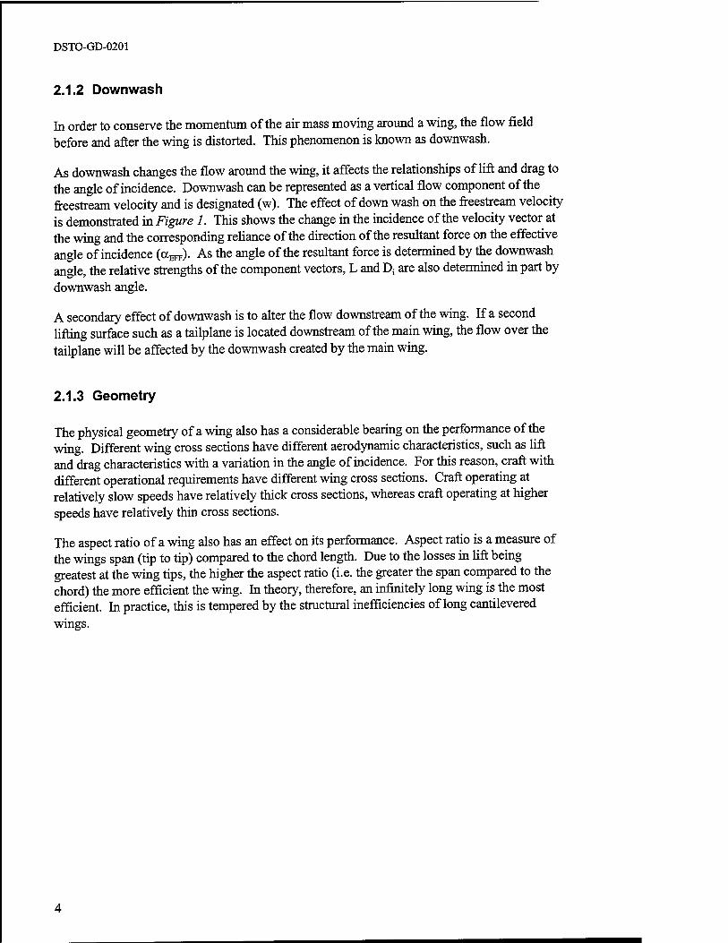
As downwash changes the flow around the wing, it affects the relationships of lift and drag to the angle of incidence. Downwash can be represented as a vertical flow component of the freestream velocity and is designated (w). The effect of down wash on the freestream velocity is demonstrated in Figure 1. This shows the change in the incidence of the velocity vector at the wing and the corresponding reliance of the direction of the resultant force on the effective angle of incidence (a^). As the angle of the resultant force is determined by the downwash angle, the relative strengths of the component vectors, L and D; are also determined in part by downwash angle.
A secondary effect of downwash is to alter the flow downstream of the wing. If a second lifting surface such as a tailplane is located downstream of the main wing, the flow over the tailplane will be affected by the downwash created by the main wing.
2.1.3 Geometry
The physical geometry of a wing also has a considerable bearing on the performance of the wing. Different wing cross sections have different aerodynamic characteristics, such as lift and drag characteristics with a variation in the angle of incidence. For this reason, craft with different operational requirements have different wing cross sections. Craft operating at relatively slow speeds have relatively thick cross sections, whereas craft operating at higher speeds have relatively thin cross sections.
The aspect ratio of a wing also has an effect on its performance. Aspect ratio is a measure of the wings span (tip to tip) compared to the chord length. Due to the losses in lift being greatest at the wing tips, the higher the aspect ratio (i.e. the greater the span compared to the chord) the more efficient the wing. In theory, therefore, an infinitely long wing is the most efficient. In practice, this is tempered by the structural inefficiencies of long cantilevered wings.
DSTO-GD-0201
2.2 Ground Effect
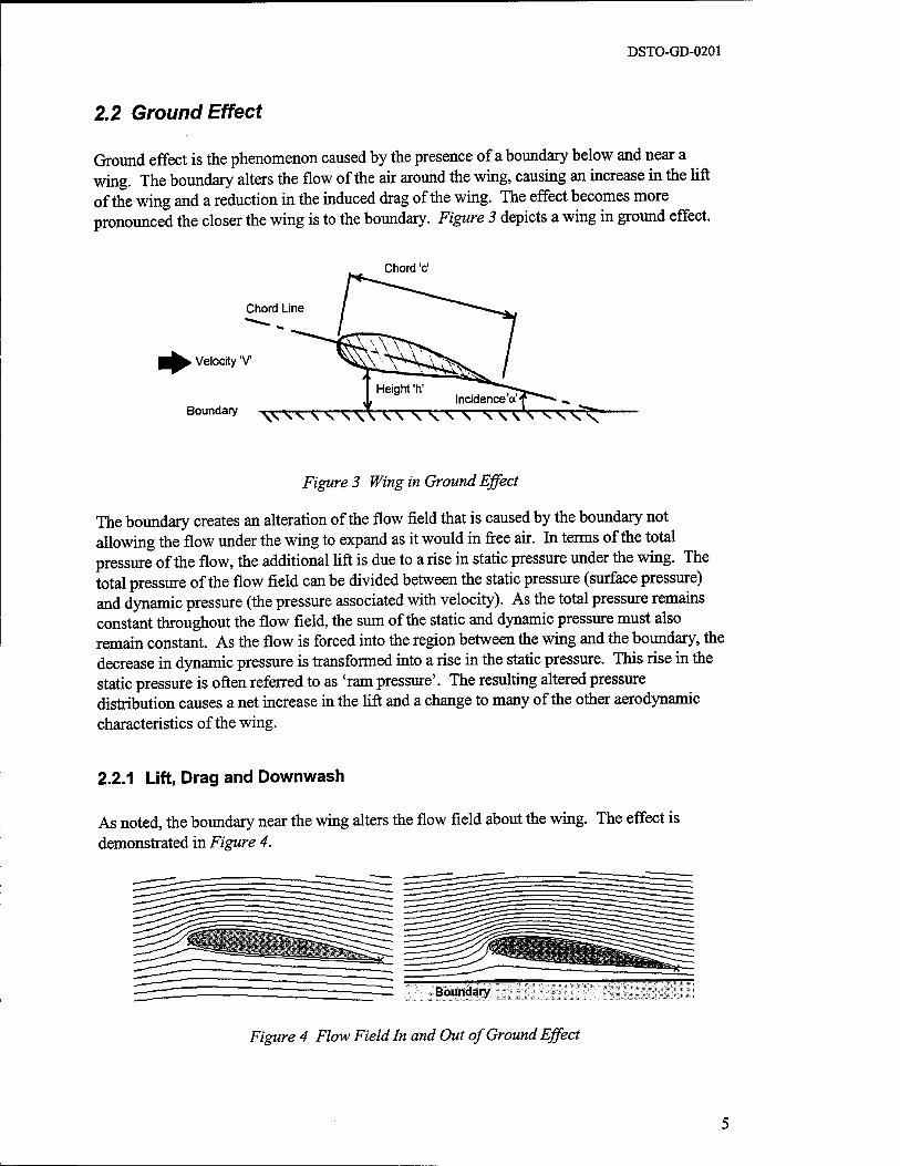
Ground effect is the phenomenon caused by the presence of a boundary below and near a wing. The boundary alters the flow of the air around the wing, causing an increase in the lift of the wing and a reduction in the induced drag of the wing. The effect becomes more pronounced the closer the wing is to the boundary. Figure 3 depicts a wing in ground effect.
Chord Line
. Velocity 'V
Boundary
Chord 'c'
W^SVSSV
Height'h' Incidence a ■
Figure 3 Wing in Ground Effect
The boundary creates an alteration of the flow field that is caused by the boundary not allowing the flow under the wing to expand as it would in free air. In terms of the total pressure of the flow, the additional lift is due to a rise in static pressure under the wing. The total pressure of the flow field can be divided between the static pressure (surface pressure) and dynamic pressure (the pressure associated with velocity). As the total pressure remains constant throughout the flow field, the sum of the static and dynamic pressure must also remain constant. As the flow is forced into the region between the wing and the boundary, the decrease in dynamic pressure is transformed into a rise in the static pressure. This rise in the static pressure is often referred to as 'ram pressure'. The resulting altered pressure distribution causes a net increase in the lift and a change to many of the other aerodynamic characteristics of the wing.
2.2.1 Lift, Drag and Downwash
As noted, the boundary near the wing alters the flow field about the wing. The effect is demonstrated in Figure 4.
Figure 4 Flow Field In and Out of Ground Effect

DSTO-GD-0201
The change in flow field has the effect of reducing the downwash angle and therefore increasing the effective angle of incidence at a given geometric angle of attack. This causes a corresponding rotation of the resultant force vector and changes to the component of lift and drag forces. The effect is to increase the lift component and reduce the induced drag component, thus increasing the lift to drag ratio. A number of experimental studies have demonstrated this effect for many aircraft wing configurations [7], [8] and [15]
The increased lift to drag ratio provides a net gain in efficiency and the reduction in drag provides the benefit of a reduced thrust requirement in cruise flight.
DSTO-GD-0201
2.3 Pitching Moment
In addition to creating lift and drag, the movement of a wing through the air creates a moment about the aerodynamic centre of the wing. This moment is known as the pitching moment and is the result of the pressure distribution on the wings surface. In a moving craft this pitching moment needs to be balanced in order to keep the craft stable. Aircraft designers typically add another lifting surface to overcome pitching moment, either at the rear of the aircraft (tailplane) or at the front of the aircraft (canard).
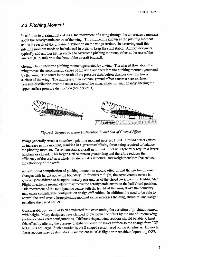
Ground effect alters the pitching moment generated by a wing. The altered flow about the wing moves the aerodynamic centre of the wing and therefore the pitching moment generated by the wing. The effect is the result of the pressure distribution changes over the lower surface of the wing. The ram pressure in extreme ground effect causes a near uniform pressure distribution over the under surface of the wing, while not significantly altering the upper surface pressure distribution (see Figure 5).
Boundary
Figure 5 Surface Pressure Distribution In and Out of Ground Effect
Wings generally create a nose down pitching moment in cruise flight. Ground effect causes an increase in this moment, resulting in a greater stabilising force being required to balance the pitching moment. To remain stable, a craft in ground effect will generally require a larger tailplane or canard. This larger surface creates greater drag and therefore reduces the efficiency of the craft as a whole. It also creates structural and weight penalties that reduce the efficiency of the craft.
An additional complication of pitching moment in ground effect is that the pitching moment changes with height above the boundary. In freestream flight, the aerodynamic centre is generally considered to be approximately one quarter of the chord back from the leading edge. Flight in extreme ground effect may move the aerodynamic centre to the half chord position. This movement of the aerodynamic centre with the height of the wing above the boundary may cause considerable configuration design difficulties. In addition, the need to be able to control the craft over a large pitching moment range increases the drag, structural and weight penalties discussed earlier.
Considerable research has been conducted into overcoming the variation of pitching moment with height. Many designers have claimed to overcome the effect by the use of unique wing sections and/or craft configurations. Different shaped wing sections should be able to limit this effect by altering the pressure distribution over the lower surface so the change from IGE to OGE is not large. Such a section is the S-shaped section used on the Amphistar. However, these sections may be dramatically inefficient in OGE flight or incapable of operating OGE
DSTO-GD-0201
and this is a likely area for further research. Planform shapes differing from conventional aircraft may provide another method to reduce the change in pitching moment.
2.3.1 Maximum Lift
The maximum lift coefficient (CLMAX) defines the low speed characteristics of the wing and the take off and landing speeds. An increase in CLMAX enables lower take off and landing speeds and therefore reduces the take off run and lowers landing loads on the structure. The CLMAX
also defines the stall speed of the wing, which defines the slow speed limit of the craft and may affect the stall characteristics of the wing.
A number of changes occur to CLMAX when a wing operates IGE. CLMAX may either increase or decrease, depending on wing section, planform shape and the use of end plates [3]. For aircraft wing sections the maximum lift coefficient is increased by increasing wing camber, however in extreme ground effect, the increase in camber has been observed to reduce the maximum lift coefficient. It has also been observed that the incidence at which stall occurs is lower for wings operating IGE and that the stall tends to be more severe, with a more dramatic loss in lift [8].
It is noted that most of the research into ground effect has been carried out using wings designed for freestream flight. Specific research into wings designed for IGE operation may provide improved wing designs. Research into aerodynamic aids for increasing lift, such as slats and slots, may be beneficial in reducing landing and take off speeds.
2.3.2 Effect of Height above the Ground
Many of the effects of flight IGE are functions of the height above the boundary. These effects are non-linear and are responsible for many of the complications inherent in the development of WIG craft. They have been researched from both an empirical viewpoint and a modelling viewpoint.
From the modelling viewpoint, three separate models have emerged, each modelling a certain zone above the boundary. These models are outlined in a paper by K. V. Rozhdestvensky [25]. The first zone is the region in which the wing is operating between the boundary and a height of 20% of the chord of the wing. This region has a high level of constriction of the flow in the vertical direction and the flow becomes two dimensional with the vertical degree of freedom of the flow is restrained.
The second zone is the region between the height of one chord length of the wing to ten span lengths. In this region, the model is dominated by the span of the wing. Inviscid flow models are used in this region and show a marginal increase in the L/D to that of OGE flight. For a wing flying in the region between 20% of the chord and one chord height, a combination of the two models are required.
Above ten span lengths, free flight models currently used in aerodynamic theory for aircraft design, are used. An understanding of these zones has enabled accurate computational methods to be devised as tools for the design of WIG craft.
DSTO-GD-0201
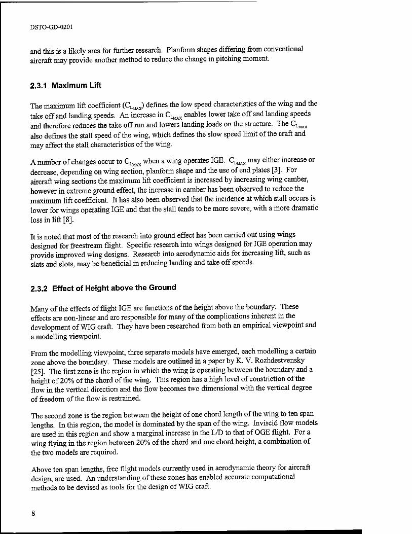
Tests on wings in ground effect were carried out by A.W. Carter [7] and some of the results are reproduced below. An example of the effect on aerodynamic parameters with height is demonstrated in Figure 6. The value of h'/b is the relative height of the trailing edge to the span of the wing. This graph shows the lift to drag ratio versus height above the boundary for two different wing cross sections. An aspect ratio of one was used for these tests. The increase in lift to drag ratio is clearly seen as the wing approaches the boundary.
Figure 6 also demonstrates the effect of end plates. Whilst aircraft have used end plates or winglets from time to time, their benefit is not universally accepted. However, for wings operating in ground effect the addition of end plates is more efficient because they increase the lift to drag ratio more than if they where used to increase the wing's span. It is also noted the end plates are more effective on wings of low aspect ratios, which are more likely to be found on WIG aircraft.
(%L
Figure 6 Lift to Drag Ratio versus Height above the Boundary [7]
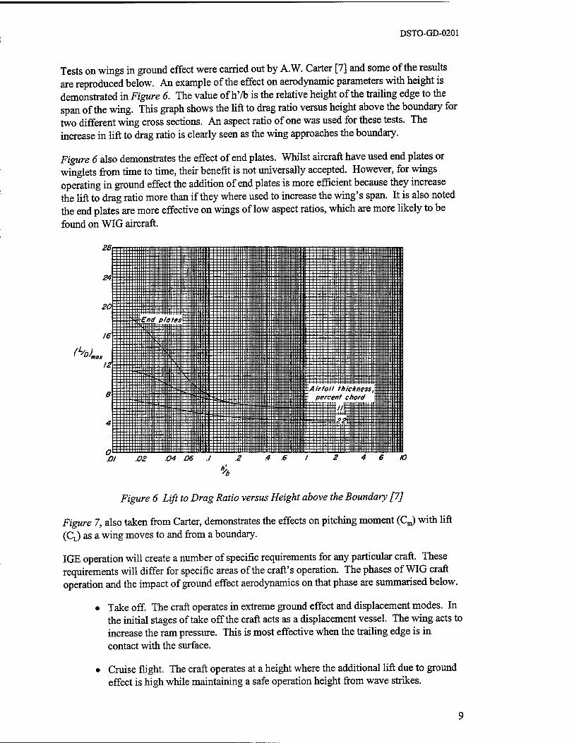
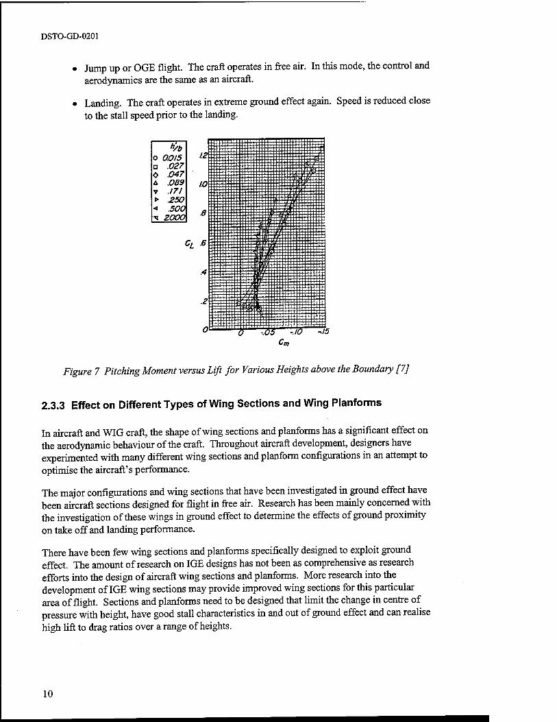
Figure 7, also taken from Carter, demonstrates the effects on pitching moment (CJ with lift (CL) as a wing moves to and from a boundary.
IGE operation will create a number of specific requirements for any particular craft. These requirements will differ for specific areas of the craft's operation. The phases of WIG craft operation and the impact of ground effect aerodynamics on that phase are summarised below.
• Take off. The craft operates in extreme ground effect and displacement modes. In the initial stages of take off the craft acts as a displacement vessel. The wing acts to increase the ram pressure. This is most effective when the trailing edge is in contact with the surface.
• Cruise flight. The craft operates at a height where the additional lift due to ground effect is high while maintaining a safe operation height from wave strikes.
DSTO-GD-0201
Jump up or OGE flight. The craft operates in free air. In this mode, the control and aerodynamics are the same as an aircraft.
Landing. The craft operates in extreme ground effect again. Speed is reduced close to the stall speed prior to the landing.
h/b o 0OI5 □ .027 0 .047 A .089 V .171 > 250 < .500 ■<J ZOOO
Figure 7 Pitching Moment versus Lift for Various Heights above the Boundary [7]
2.3.3 Effect on Different Types of Wing Sections and Wing Planforms
In aircraft and WIG craft, the shape of wing sections and planforms has a significant effect on the aerodynamic behaviour of the craft. Throughout aircraft development, designers have experimented with many different wing sections and planform configurations in an attempt to optimise the aircraft's performance.
The major configurations and wing sections that have been investigated in ground effect have been aircraft sections designed for flight in free air. Research has been mainly concerned with the investigation of these wings in ground effect to determine the effects of ground proximity on take off and landing performance.
There have been few wing sections and planforms specifically designed to exploit ground effect. The amount of research on IGE designs has not been as comprehensive as research efforts into the design of aircraft wing sections and planforms. More research into the development of IGE wing sections may provide improved wing sections for this particular area of flight. Sections and planforms need to be designed that limit the change in centre of pressure with height, have good stall characteristics in and out of ground effect and can realise high lift to drag ratios over a range of heights.
10
DSTO-GD-0201
Wing planforms also have a definitive effect on a craft's aerodynamic behaviour. Research into optimum planform shapes for IGE operation may also result in improved characteristics.
2.4 Theoretical Benefits of Ground Effect
The theoretical efficiencies of airborne craft can be expressed in terms of their ability to carry a given payload over a given distance. This efficiency is directly related to the craft's lift to drag ratio. WIG craft's higher lift to drag ratio, provide them with the potential for greater efficiencies than aircraft.
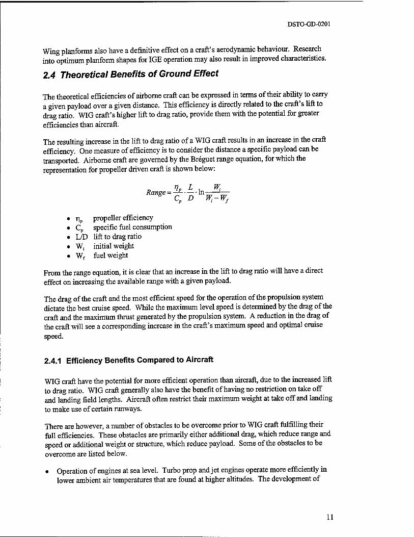
The resulting increase in the lift to drag ratio of a WIG craft results in an increase in the craft efficiency. One measure of efficiency is to consider the distance a specific payload can be transported. Airborne craft are governed by the Breguet range equation, for which the representation for propeller driven craft is shown below:
Range -'lp -L -In Wi g Cp D W,-Wf
Tip propeller efficiency
cP specific fuel consumption
L/D lift to drag ratio w, initial weight wf fuel weight
From the range equation, it is clear that an increase in the lift to drag ratio will have a direct effect on increasing the available range with a given payload.
The drag of the craft and the most efficient speed for the operation of the propulsion system dictate the best cruise speed. While the maximum level speed is determined by the drag of the craft and the maximum thrust generated by the propulsion system. A reduction in the drag of the craft will see a corresponding increase in the craft's maximum speed and optimal cruise speed.
2.4.1 Efficiency Benefits Compared to Aircraft
WIG craft have the potential for more efficient operation than aircraft, due to the increased lift to drag ratio. WIG craft generally also have the benefit of having no restriction on take off and landing field lengths. Aircraft often restrict their maximum weight at take off and landing to make use of certain runways.
There are however, a number of obstacles to be overcome prior to WIG craft fulfilling their fu.ll efficiencies. These obstacles are primarily either additional drag, which reduce range and speed or additional weight or structure, which reduce payload. Some of the obstacles to be overcome are listed below.
• Operation of engines at sea level. Turbo prop and jet engines operate more efficiently in lower ambient air temperatures that are found at higher altitudes. The development of
11
DSTO-GD-0201
engines specifically designed to operate at low levels may recover some efficiencies lost by the use of aviation specific engines.
• Seaborne hull. If a sea worthy hull is required, then like seaplanes the hull adds drag and increased structural weight.
• Overcoming pitching moment. If larger or additional balancing surfaces are required, additional drag and structure are incurred.
• Additional thrust required at take off. The far greater amount of thrust required at take off, compared to that required in cruise means that additional engine capacity is carried either in the form of additional engines or under utilised engines. This may cause inefficiencies both in terms of drag and structure.
2.4.2 Comparison to Water Borne Craft
A comparison of WIG craft to water borne craft shows an obvious potential speed advantage. Large displacement craft have high fuel efficiencies with large payload volumes and weights. WIG craft have the potential to carry heavy payload weights while operating at high speed. Unlike conventional waterborne craft, WIG craft are not speed limited in high sea states. Whilst their range or payload ability may be reduced in heavy seas, there is no substantial reduction in cruise speed. WIG craft are limited to sea state conditions at take off and landing, imposing a restriction on their operation.
Conventional water craft have a high degree of fuel efficiency. This is in part due to their propulsive system as well as their low speed. As drag is a function of the square of the speed operation at low speed increases the craft's efficiency. The maximum speed of water borne craft is limited by drag. For displacement craft, this corresponds to the dramatic increase in wave drag resulting in a maximum speed of 30 - 50 knots. It is normal to limit the speeds of displacement craft for sea state conditions due to the loading on the structure.
For hydrofoils, the speed limit is due to cavitation on the lifting water wing. This corresponds to a speed of 50 - 80 knots. For the operation of hydrofoils in increasing sea state, the reduction in speed is less severe as the hydrofoil lowers the loading on the ship structure.
Hovercraft and Surface Effect Ships (SES) have a maximum forward speed of approximately 100 knots on flat water. This is severely reduced with increasing sea state.
12
DSTO-GD-0201
2.5 Stability and Control in Ground Effect
Due to the aerodynamic influences of ground effect there is a corresponding change to the dynamics response of the craft. Stability and control have been the greatest hurdles in the early development of WIG craft due to the non linear dependence of aerodynamic characteristics with height.
2.5.1 Height Stability
Height stability is defined as the ability of a craft to maintain or return to its initial height after a disturbance in height. This does not include the changes of height coupled with pitch motion. The height stability of WIG craft is governed by the behaviour of the lifting body as it approaches the boundary.
WIG craft height stability can be explained by considering the effect on lift with changes in height. The stable case is achieved when a decrease in height results in an increase in lift and vice versa. Under these conditions the increased lift has the effect of restoring the craft to the original height. Thus, if the craft is disturbed in height the lift force will act to restore the craft to the original height.
In the opposite case, the craft will be unstable in height if the lift force acts to amplify the change in height. In this case a decrease in height will result in a decrease in lift. This decrease in lift will result in the aircraft accelerating further towards the ground, a result enforced by the variation of lift with height.
It has been demonstrated that WIG craft can be designed to be very stable in height. The lift force is known to increase with a decrease in height for WIG craft. It has been noticed on aircraft that the additional lift due to ground effect often makes the aircraft "coast" before landing.
An example of the ability of WIG craft to withstand large perturbations in height was given by the Russian Lun craft. This craft was designed to carry and launch six surface to surface missiles. During weapon trials at sea, the craft launched six missiles simultaneously which altered its height by approximately 0.5 m after which it returned to its original height [20].
2.5.2 Pitch Stability
Pitch stability is a measure of the response of the craft to changes in pitch. With a disturbance in pitch the response of the craft can be either stable or unstable. Unstable behaviour results in increasing pitch amplitudes, while stable behaviour results in the craft returning to a pitch angle.
The control of WIG craft pitch stability has been one of the larger hurdles in WIG craft development. The problem is due to a change in the pitch stability with height. The result is the necessity for a large amount of control power to maintain trim. Early designs and theoretical studies have shown that the greatest problem is damping the long period (phugoid) oscillations.
13
DSTO-GD-0201
Designs have often shown stability in some regions above the surface and instability in other regions. Pitch instability causes ride discomfort and is a possible hazard to the craft. As the pitch stability is linked to the vertical height stability, large excursions could cause contact with the surface, resulting in high structural loads or failure.
It is now considered [3] that this problem can be overcome using modern control methods and the current understanding of WIG craft aerodynamics. The challenge in the design phase is to provide sufficient control power for stability to be maintained throughout the vertical height envelope.
2.5.3 Directional Control and Manoeuvrability
Lateral or directional stability has not been a heavily researched area. This is due to the perceived ability of WIG craft to maintain a level attitude with perturbations in roll angle. Roll stability is generally assured due to the lower wing generating more lift as it comes closer to the surface causing the craft to roll back to the neutral position. A complication to this is the reduced drag on the lower wing. This should cause the craft to diverge directionally from the initial path. This might be overcome by the use of a vertical fin.
The directional control and manoeuvrability of WIG craft are dependent on its ability to fly out of ground effect. If it is incapable of flying out of ground effect, its control will be similar to other vehicles limited to two dimensions such as hovercraft and ships. However, if a craft is capable of OGE flight, its controls will need to be more complicated and hence more like a conventional aircraft.
For WIG craft there are two main options in effecting a turn dependent on the crafts ability to fly out of ground effect. The most efficient method is to manoeuvre like an aircraft, that is to fly out of ground effect and use banked turns, known as zoom turns. Many of the USSR designed craft and the craft of RFB used zoom turns.
For those WIG craft that are incapable of OGE flight zoom turns are not an option. These craft need to perform turns only in the horizontal plane. This is achieved by the rudder with the wings level. This type of turn has a much larger turn radius than a zoom turn.
Manoeuvrability and control are related to the amount of control power and can be greatly affected by such things as the position of the centre of gravity, the weight and speed. For design, manoeuvring requirements dictate the quantity of control power required. Current fly by wire control systems provide a high degree of manoeuvrability, however there remains the need for sufficient control power, either from lifting surfaces like elevators, ailerons or rudders or from thrust vectoring.
2.5.4 Speed Stability
Speed stability is defined as the ability to maintain a speed and the method of control over that speed. Aircraft are designed to be inherently stable in speed. The pilot alters the craft's speed by changes in the incidence of the aircraft. For WIG craft speed stability is governed by two variables, height and incidence.
14

DSTO-GD-0201
In aircraft, the incidence governs the aircraft's speed and this is controlled through the elevator. The aircraft's incidence defines the lift coefficient that can be achieved by the wing and the resultant forward velocity is defined for the weight of the aircraft. This means that for a downward elevator deflection the craft will increase speed until the required lift force is achieved.
In WIG craft, the lift coefficient is a function of both height and incidence. For WIG craft the response is defined by the position of the centre of gravity. Dependent on the position of the centre of gravity, a change in speed may result in a change in incidence or a change in height. Pure speed changes resulting in height changes; occur at one extreme of the centre of gravity envelope. At the other, speed changes will result in pure changes of incidence. Between these extremes, speed changes will result in a combination of both height and incidence.
Dependent on the design, these considerations may form limitations on the centre of gravity range for the craft. Other stability issues, such as longitudinal stability and the ability for transition from IGE to OGE may be more critical.
15

DSTO-GD-0201
3 HISTORICAL PERSPECTIVE
The development of ground effect craft stems from observations made in the 1920's on the landing performance of aircraft. Soon after, in 1921, a theoretical understanding of ground effect was achieved [13]. Later a number of countries, namely the USA and the USSR, became interested in attempting to exploit the potential benefits of ground effect. Early developments in the 1960's saw a number of experimental craft designed by these countries. The USA abandoned efforts to produce ground effect craft in the mid 1960's in favour of Surface Effect Ship development. Germany began work in the late 1960's using the designs of Alexander Lippisch. However the undisputed leader, in research and development up to the late 1980's was the USSR.
From the 1960's until the present, the USA has monitored the development of WIG craft. A number of studies have been completed analysing the viability and advantages of using such craft for military applications. The USA has commissioned a large amount of theoretical and experimental research, as well as conceptual design studies into WIG craft. However, this research has not lead to the development of an operational test craft.
Recent developments have been on WIG craft of a smaller size, two to 16 person capacity, in countries such as Germany, Russia, China, USA and Australia. Current investment and innovation has been directed towards civil applications, leading to the development of a small number of recreational craft. There have also been conceptual design proposals for large ferry and transport craft. These proposals have been suggested as alternatives for heavy payload and long range cargo transport aircraft. None of these proposals, at this time, has been pursued to the development stage.
3.1 History to Date
Ground effect is a phenomenon that has been noticed for some time. Early aviators noticed the increased lift on landing when their aircraft approached the ground. Also predominant was an effect, which resulted in lift being suddenly lost, resulting in what was termed a "pancake landing". In the 1920's the effect was studied to gain a theoretical understanding. In 1921 Wieselsberger [10] published a study which still holds as a sufficiently accurate approximation for ground effect on planar wing performance explaining the increased lift. While experimental studies found the sudden loss in lift was due to the aerofoils geometry in ground effect. With this understanding the effects of ground effect on the landing characteristics of aircraft were reduced. A number of early aircraft used the additional lift from ground effect to increase their efficiency. The transatlantic Dornier DO-X flew just above wave height. The increased lift to drag ratio due to ground effect gave the Dornier the required range to complete its mission. Bomber pilots in the Second World War who had lost an engine would use ground effect by flying low over the water. The resulting increased lift to drag ratio allowed them to achieve the required range to return safely.
Early attempts to design and build ground effect vehicles where hampered by a lack of take off power to overcome the water drag. It was not until the 1960's that real interest started in developing craft to solely exploit the benefits of ground effect. Reputedly the first to have
16
DSTO-GD-0201
designed a craft to deliberately fly using ground effect was Fin Kaairo [10] and then Alexander Lippisch in the USA in 1963. Many countries around the world started research and development into ground effect craft. Much of the work was done in the USA, USSR and Japan. This spate of development resulted in a number of experimental studies using model testing and prototype craft.
Soon after the completion of the design and testing of the X-l 12 by Lippisch, the USA decided that a more fruitful area for research would be in the development of Surface Effect Ships (SES) (large cargo sized hovercraft). In the opinion of Stephen Hooker [14] the decision was made under the reasoning that the development of a fast craft would be easier to achieve with lower cost and with less risk through SES. The results of model tests showed WIG craft to have poor performance due to take off and landing considerations [10]. As a result of the removal of military funding from the development of WIG craft in the USA, the Lippisch design for the X-l 12 was sold to a Germany company Rhein Flugzeugbau GmbH (RFB).
In the USSR, development funded by the military continued throughout the 1960's. Development in the USSR was under the leadership of hydrofoil craft designer Dr Rostislav Alexeyev at the Central Design Bureau of Hydrofoil Craft (CDBHC). In 1966, the KM, the largest WIG craft built to date, started sea trials. KM is better known in the West as the "Caspian Sea Monster" [15] and [16]. This period of research resulted in the development of a large range of test craft. Most of the data and theoretical understanding of the design of WIG craft stems from this period. This enabled the formation of design rules and appropriate testing procedures for WIG craft. The result was a number of experimental craft tested and the development of four production craft.
With the first operational pictures obtained by the West of operational Russian WIG craft the US military reviewed how to combat such a vehicle. The conclusion at the time was that WIG craft where a technology that the US military did not needed to cultivate. However it was observed that it was an area which needed to be understood in terms of its potential capabilities [12].
The 1970's saw the Soviet military bring the first WIG craft into operational service. This was brought into fruition with the development of the A.90.150 Orlyonok, troop transport and assault craft. The first craft entered operation in 1979 with two others joining it in 1981 and 1983 [20]. The operation of these craft, in the Russian Navy, proceeded over a period of more than ten years until the early 1990's. In other parts of the world WIG craft development was less emphatic. A potential solution for increasing the landing and take off performance was found in the early 1970's. This resulted in a number of studies into Power Augmentation of Ram Wing In Ground effect craft (PAR-WIG craft) being conducted. In the mid 1970's the Advanced Naval Vehicle Concepts Evaluation team conducted tests which pointed to PAR- WIG craft having very high efficiencies [11]. Lockheed Georgia carrying out preliminary design of a PAR-WIG craft as a proposed heavy lift platform for the US Navy [15].
The cancellation of development for WIG craft was the result of the go ahead for the construction of the C-5A Galaxy, in the late 1960's as the designated heavy lift platform for the US military [14] [15]. The decision was based on the perceived likelihood that the technology and risk associated with the development of the Galaxy was lower than the development of a WIG craft.
17
DSTO-GD-0201
Developments in WIG craft proceeded in Germany through the research of two companies; Botec who's principle designer is Günther Jörg and RFB. Jörg used the original Russian tandem wing design to prototype a number of craft, while RFB pursued the Lippisch design with the development of the X-l 13 and X-l 14 WIG craft. Lippisch returned to Germany from the US to work with RFB on the new development [15]. RFB received sponsorship from the German military for the development of these prototype craft.
The 80's saw the USSR begin to produce a number of craft before the dismantling of the Soviet Block. In 1989 the missile craft the Lun was commissioned for trial operations. The craft carried six surface to surface missiles and was trialed for a period of three years.
Since the dismantling of the USSR, enthusiasts, academics and research organisations have done much of the work into WIG craft. The craft produced have been small two to eight seat craft, primarily prototypes, with some having small production runs. A number of civilian conferences have been held in the 1990's dealing with fast sea transport and focussing on WIG craft, these include:
• 1993 Yokohama, "Fast 1993", Second International Conference on Fast Sea Transportation, 13-16 December, 1993.
• 1995 Sydney, "A Workshop on Twenty-First Century Flying Ships" at the University of New South Wales, 7-8 November, 1995.
•
•
1996 Sydney, "Ekranoplans and Very Fast Ships" at the University of New South Wales, 5-6 December 1996.
1997 London, Royal Institution of Naval Architects (RINA) International Conference on WIGs, 4-5 December 1997.
The US military has conducted a number of studies into WIG craft. These reports have mainly focussed on the ability of WIG craft to fulfil operational roles with prime consideration to development cost and potential advantages over existing technologies, these include:
• ARPA Wingship Investigation, Sept 94, [1], [2] and [3].
• Airlift 2025, and
• US Navy Strategic Studies Group XVI.
In recent times a number of manufacturers have proposed large WIG craft to fulfil gaps in the heavy lift fast transportation market. None of these designs has raised the funding required to develop such a craft.
18
DSTO-GD-0201
3.1.1 WIG Craft Terminology
There are a number of different terms in common use for wing in ground effect craft. Throughout this report "WIG craft" will be used to refer to the whole class of vehicles designed for using ground effect to generate lift in their cruise operation. These craft may or may not be capable of OGE flight.
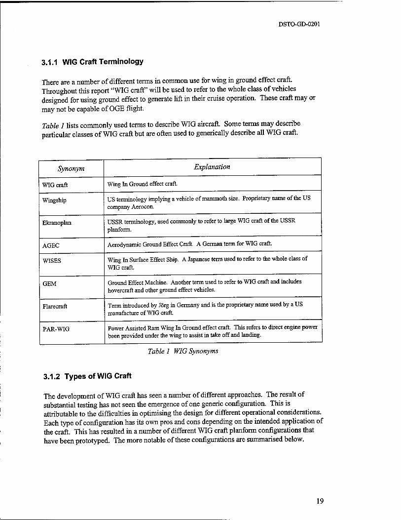
Table 1 lists commonly used terms to describe WIG aircraft. Some terms may describe particular classes of WIG craft but are often used to generically describe all WIG craft.
Synonym
WIG craft
Wingship
Ekranoplan
AGEC
WISES
GEM
Flarecraft
PAR-WIG
Explanation
Wing In Ground effect craft.
US terminology implying a vehicle of mammoth size. Proprietary name of the US company Aerocon.
USSR terminology, used commonly to refer to large WIG craft of the USSR planform.
Aerodynamic Ground Effect Craft. A German term for WIG craft.
Wing In Surface Effect Ship. A Japanese term used to refer to the whole class of WIG craft.
Ground Effect Machine. Another term used to refer to WIG craft and includes hovercraft and other ground effect vehicles.
Term introduced by Jörg in Germany and is the proprietary name used by a US manufacture of WIG craft.
Power Assisted Ram Wing In Ground effect craft. This refers to direct engine power been provided under the wing to assist in take off and landing.
Table 1 WIG Synonyms
3.1.2 Types of WIG Craft
The development of WIG craft has seen a number of different approaches. The result of substantial testing has not seen the emergence of one generic configuration. This is attributable to the difficulties in optimising the design for different operational considerations. Each type of configuration has its own pros and cons depending on the intended application of the craft. This has resulted in a number of different WIG craft planform configurations that have been prototyped. The more notable of these configurations are summarised below.
19
DSTO-GD-0201
3.1.2.1 Ram Wing
The ram wing terminology strictly refers to a wing, which is in contact with the ground at the trailing edge. The air is rammed into the closed cavity increasing the pressure. This effect on the lift is generated by the wing and ground plane and is referred to as ram pressure. A number of WIG craft use this concept to take off.
The ram wing planform consists of a small span wing of low aspect ratio. This wing is usually straight and of zero taper. For stability a tail surface is needed which is positioned out of ground effect. Due to the inherent instability of the wing the tail area is large, typically 50% of the main wing and of similar span. This large tail surface acts to stabilise the craft at different heights above the ground plane.
Other parameters common to this type of design are optimal cruise heights above the surface corresponding to approximately 10 to 25% of the wing cord. A current innovation to improve the stability and reduce the required tail area is the use of S-shaped wing sections. Experiments with end plates have been conducted in an effort to lower the induced drag even further and increase the effective aspect ratio.
Russian designers have favoured the ram wing configuration. It is used extensively on a number of large Ekranoplans and smaller WIG craft developed in Russia.
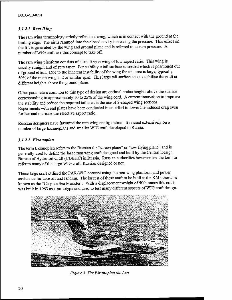
3.1.2.2 Ekranoplan
The term Ekranoplan refers to the Russian for "screen plane" or "low flying plane" and is generally used to define the large ram wing craft designed and built by the Central Design Bureau of Hydrofoil Craft (CDBHC) in Russia. Russian authorities however use the term to refer to many of the large WIG craft, Russian designed or not.
These large craft utilised the PAR-WIG concept using the ram wing planform and power assistance for take off and landing. The largest of these craft to be built is the KM otherwise known as the "Caspian Sea Monster". With a displacement weight of 500 tonnes this craft was built in 1963 as a prototype and used to test many different aspects of WIG craft design.
-_ - -
Figure 8 The Ekranoplan the Lun
20
DSTO-GD-0201
The craft designed by the CDBHC in the 1960's to 1980's represent the first generation of WIG craft. These craft have recognised inefficiencies on a number of levels [12].
• These craft were structurally inefficient with high structural weights compared to payload weight. This stems mainly from an over strengthening of the craft hull for worse than expected seaworthiness.
• The landing and take off performance was no better than a seaplane with a very high power requirement for take off and high structural loads in both take off and landing.
• The craft experienced corrosion problems due to the operating environment. In particular, there were difficulties with engines operating in highly corrosive and high foreign object damage (FOD) environments. Structural reliability also becomes an issue in such corrosive environments.
• Their aerodynamic performance was at best equal to aircraft. With shapes and configurations similar to aircraft.
The USSR designers have acknowledged that the first generation of craft represents the preliminary design. They state that there is potential for further development resulting in greater efficiencies. They cite that this can be achieved by attention to the aforementioned deficiencies in the first generation [27].
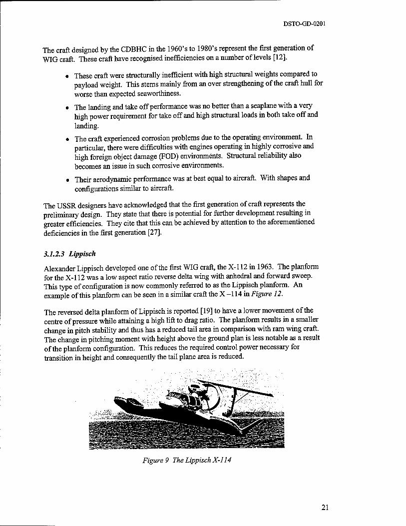
3.1.2.3 Lippisch
Alexander Lippisch developed one of the first WIG craft, the X-l 12 in 1963. The planform for the X-l 12 was a low aspect ratio reverse delta wing with anhedral and forward sweep. This type of configuration is now commonly referred to as the Lippisch planform. An example of this planform can be seen in a similar craft the X -114 in Figure 12.
The reversed delta planform of Lippisch is reported [19] to have a lower movement of the centre of pressure while attaining a high lift to drag ratio. The planform results in a smaller change in pitch stability and thus has a reduced tail area in comparison with ram wing craft. The change in pitching moment with height above the ground plan is less notable as a result of the planform configuration. This reduces the required control power necessary for transition in height and consequently the tail plane area is reduced.
Figure 9 The Lippisch X-l 14
21
DSTO-GD-0201
The Lippisch patent was bought by the German company RFB which have designed a number of craft based on the planform. The craft designed on this planform have been tested for military applications and developed for recreational use. These craft have not reached the high displacement weights of the Russian Ekranoplans however designs using a similar planform and utilising a flying wing have been mooted by a US company Aerocon.
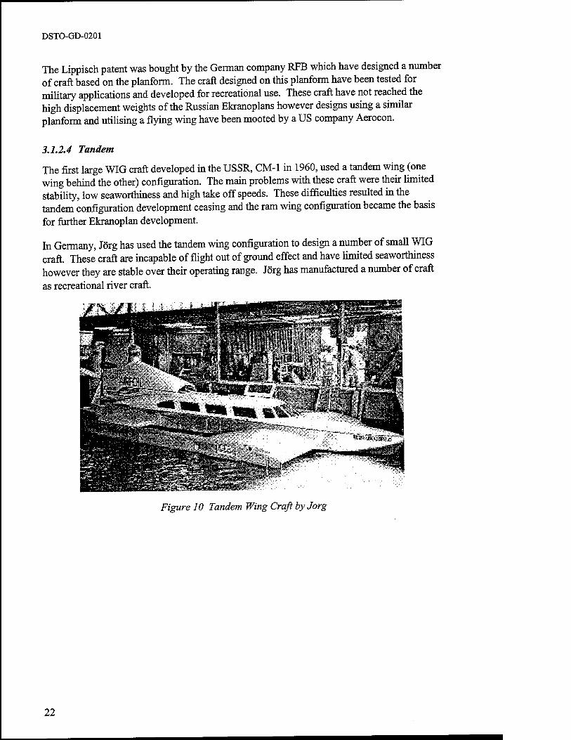
3.1.2.4 Tandem
The first large WIG craft developed in the USSR, CM-1 in 1960, used a tandem wing (one wing behind the other) configuration. The main problems with these craft were their limited stability, low seaworthiness and high take off speeds. These difficulties resulted in the tandem configuration development ceasing and the ram wing configuration became the basis for further Ekranoplan development.
In Germany, Jörg has used the tandem wing configuration to design a number of small WIG craft. These craft are incapable of flight out of ground effect and have limited seaworthiness however they are stable over their operating range. Jörg has manufactured a number of craft as recreational river craft.
Figure 10 Tandem Wing Craft byJorg
22
DSTO-GD-0201
3.2 Production WIG Craft
The most notable of the WIG craft which have been produced are those of the former USSR. The (CDHBC) have designed a number of WIG craft capable of speeds as high as 250 knots and displacement weights of 500 tonne.
Much of the research and construction in Russia has declined with the dismantling of the USSR and the associated reduction in defence spending. Since 1989 a number of smaller craft have been prototyped and some have reached limited production as recreational craft.
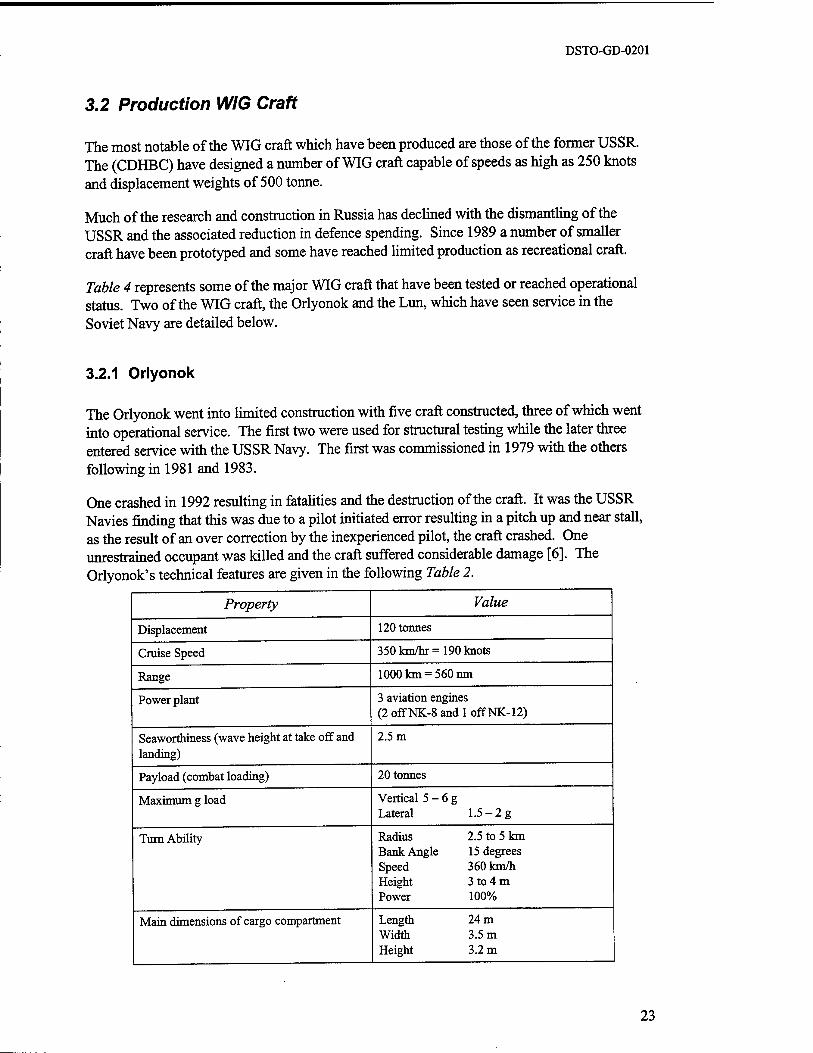
Table 4 represents some of the major WIG craft that have been tested or reached operational status. Two of the WIG craft, the Orlyonok and the Lun, which have seen service in the Soviet Navy are detailed below.
3.2.1 Orlyonok
The Orlyonok went into limited construction with five craft constructed, three of which went into operational service. The first two were used for structural testing while the later three entered service with the USSR Navy. The first was commissioned in 1979 with the others following in 1981 and 1983.
One crashed in 1992 resulting in fatalities and the destruction of the craft. It was the USSR Navies finding that this was due to a pilot initiated error resulting in a pitch up and near stall, as the result of an over correction by the inexperienced pilot, the craft crashed. One unrestrained occupant was killed and the craft suffered considerable damage [6]. The Orlyonok's technical features are given in the following Table 2.
Property Value
Displacement 120 tonnes
Cruise Speed 350km/hr = = 190 knots
Range 1000 km = i 560 nm
Power plant 3 aviation engines (2 off NK-8 and 1 off NK-12)
Seaworthiness (wave height at take off and landing)
2.5 m
Payload (combat loading) 20 tonnes
Maximum g load Vertical 5 - Lateral
6g 1.5-2g
Turn Ability Radius Bank Angle Speed Height Power
2.5 to 5 km 15 degrees 360 km/h 3 to 4 m 100%
Main dimensions of cargo compartment Length Width Height
24 m 3.5 m 3.2 m
23
DSTO-GD-0201
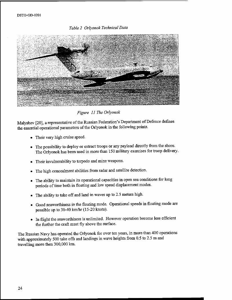
Table 2 Orlyonok Technical Data
Figure 11 The Orlyonok
Malyshev [20], a representative of the Russian Federation's Department of Defence defines the essential operational parameters of the Orlyonok in the following points.
• Their very high cruise speed.
• The possibility to deploy or extract troops or any payload directly from the shore. The Orlyonok has been used in more than 150 military exercises for troop delivery.
• Their invulnerability to torpedo and mine weapons.
• The high concealment abilities from radar and satellite detection.
• The ability to maintain its operational capacities in open sea conditions for long periods of time both in floating and low speed displacement modes.
• The ability to take off and land in waves up to 2.5 meters high.
• Good seaworthiness in the floating mode. Operational speeds in floating mode are possible up to 30-40 km/hr (15-20 knots).
• In flight the seaworthiness is unlimited. However operation become less efficient the further the craft must fly above the surface.
The Russian Navy has operated the Orlyonok for over ten years, in more than 400 operations with approximately 500 take offs and landings in wave heights from 0.5 to 2.5 m and travelling more then 300,000 km.
24
DSTO-GD-0201
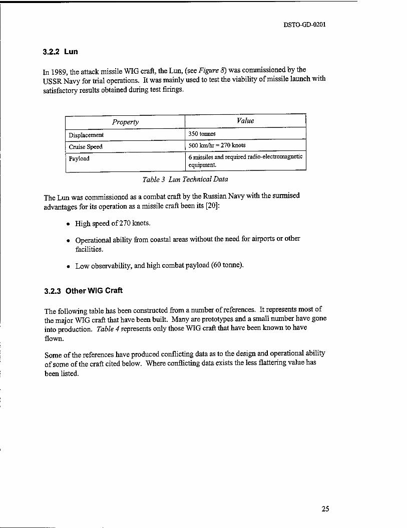
3.2.2 Lun
In 1989, the attack missile WIG craft, the Lun, (see Figure 8) was commissioned by the USSR Navy for trial operations. It was mainly used to test the viability of missile launch with satisfactory results obtained during test firings.
Property Value
Displacement 350 tonnes
Cruise Speed 500 km/hr = 270 knots
Payload 6 missiles and required radio-electromagnetic equipment.
Table 3 Lun Technical Data
The Lun was commissioned as a combat craft by the Russian Navy with the surmised advantages for its operation as a missile craft been its [20]:
• High speed of 270 knots.
• Operational ability from coastal areas without the need for airports or other facilities.
• Low observability, and high combat payload (60 tonne).
3.2.3 Other WIG Craft
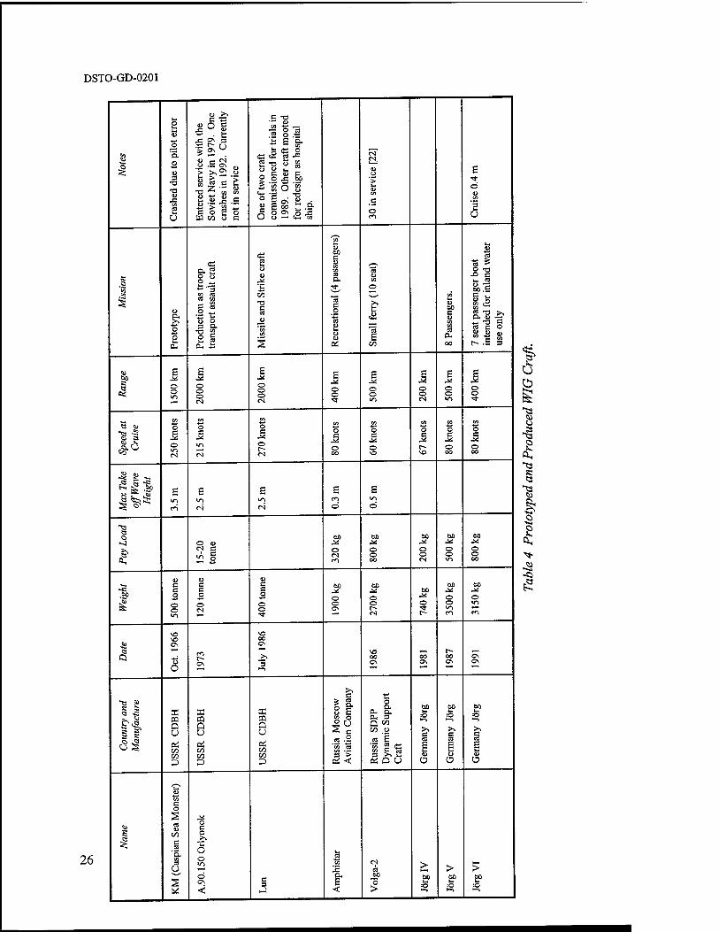
The following table has been constructed from a number of references. It represents most of the major WIG craft that have been built. Many are prototypes and a small number have gone into production. Table 4 represents only those WIG craft that have been known to have flown.
Some of the references have produced conflicting data as to the design and operational ability of some of the craft cited below. Where conflicting data exists the less flattering value has been listed.
25
DSTO-GD-0201
26
8
o ti tu
ts 'S. o eu 3
•a •a cu
•s »- u E
nter
ed s
ervi
ce w
ith th
e So
viet
Nav
y in 1
979.
One
cr
ashe
s in 1
992. C
urre
ntly
no
t in
serv
ice
i
One
of t
wo
craf
t co
mm
issi
oned
for
tria
ls in
19
89.
Oth
er c
raft
moo
ted
for
rede
sign
as
hosp
ital
ship
.
tN I_J
U Ü
'2 a> CO
,B
O
£
© CU CO
s
o
u a.
o o *-■ ft-
« o. 2 8 ü M (8 C3 CO
g S
1 a ° 1
es
o eu
B oo -a s a e
'w CO
2
CO
CJ
bO B CJ CO CO es P. ;* 's fi _o
C3 tu
Ü cu
Oi
ts <u CO
O
£ 00
CO
u 60 S u CO CO es
OH
00
o
ts ts ^ O T3 •° 1 l~ cs CU -B 60 .5 a ^ CO (9 CO ^* 2 "O >. *• "° s es ß O
8|8 I-- .5 3
c
es;
£ © o
s o o o tN
£ o o o <s
E o o ■3-
£ © o in
i © © tN
1 © © >n
1 © ©
« CD co
o B
O m tN
CO
O B
m
tN
CO
o B
J< O (-• <N
CO
o B
O 00
CO
o B
© SO
to O B
SO
CO
O
© 00
CO
o
© oo
Max
Tak
e off
Wav
e H
eigh
t
£
rn
£
tN
E in tN
E
©
£ m ©
a o
O CD
^ B 2 I
60 .*! O tN
o o oo
60
O O tN
60 -^ O © >n
60
© © 00
eu B B O
O o in
Ü B B O
o tN
CU B B O
O o
60 J^ O o Os
6ß
o ©
tN
60
©
60
© © in
60
© >n
1 SO so C\
o o OS
VO oo OS
>. ~5
SO 00 Os
oo Os
r- 00
OS
3 S
33 m Q u Pi oo oo
33 CQ a u pi 00 00
33 pa Q U
Pi 00 00 D
o C
S6 S B .2 -B io Oj CO -r- 3 >
Oi <
o ft. a. 0- 3 Q M
00 .O
es £ 'to 2 <ö 3 ^ v-
OS D U
£? CO
>s
g
CU
Ü
£? O
>s
s U
Ü
Ef :0
>. B et)
g Ü
tu
s
<L>
CO
C O
s CS U
00 B es
'5. CO C3 u
o B O _>> O o >n
ö Os
<i B 3
is "to
a. E <
tN i es op
>
> 00 ll :0
> 60 I- =0 *-*
>
1 ID o
■8
a *?
I ,<s1-

DSTO-GD-0201
g eg ^^
0 rü
3 '5. 0 *7*
£ 0 .5 60
•si a —
U 0
£ i<! |2
3 <u .b 0 >s <; •° C tu *J •- JS
a co c OH 3 B
s o
<o B '
2 „ O £ U w ,_ 60 co a « .g
. * § a
C3 I)-!
s a .2 ö
CO *j
> CO
0 "0 '£ u > a.
CO CO
D B
3 s e 0 0 e
■U CO CO 0 > «
■g L. &, fc.<2 vo
fr a .2
c 0
! 0 0 c
a ir?2 )-■ a
s <= •2 .2 a 0
o.'a 0 0 S °. .2 * f) C CN
1^ S
IE 0 > CO u
.2 12 <2 1
Sa&S ■ <j 5 Sen BJlTi on
_0> 0O
F5 "« Jo Ü
0
0
0.
CD
0 0 »-
cw u
0 21
'S §
'S 0 CO 0
"bö
CO £ IN a.
a u 3 to sa
S S 0
O C/3 1- CO
PU Cu
0 2 g U 13 c2
C
8> E E O
E
OS 0 r-
O O
I
0 0
e «) CO CO CO
CO
O CO *-> CO CO
8 .5 O c
O C
O e 0 0 p 5 #° vo VO
CO 00
0 VO VO
Max
Tak
e off
Wav
e H
eigh
t
e 0
E •0
E >n 0
-a 0 0 00 60 60 60
<1 ^i *l ^ >s O O iri i= o\ O VO 0, CO ^^
$ 60 60 •St!
60
O 60 60 60
A:
£ 0 10 O O in 00
vo Os t— f<1 CO
S s r- 0 t- ro •* Q 0\ r» t- vo
o\ c^ o\ 0 ~ ^ *"' ^^
K a O j:
<u
E § £•5 S u
1 s
0 e
JS 0 u H >>> s» C co
.S E
C 3 5 »^ P £i>C0
O E 6
«1 •33 Ü 5 i >-■ 00 C 3 2 S ^ c SPS <° B, » DES
'S en
CO
O § < E
a 0 u
E <
1 0 CO u
JS O
«< 'A o
-E 0 c <3 5 O ti-
5 2 a> 0 5 U
!/3 •c '3 <u U zn U
0 60 C u
JS
<u <U 0 >
Ä > 60 C s ro
1 X £ JS *—• ■* r-i 0 H > 1
X X 1
tN 1 a 0
27
DSTO-GD-0201
3.3 Current Technology and Research
WIG craft developed since the 1980's have been primarily smaller craft designed for the recreational and civilian ferry markets. Germany, Russia and the US have provided most of the momentum with some development in Australia, China, Japan and Taiwan. In these countries small craft up to 10 seats have been designed and built. Other larger designs as ferries and heavy transports have been proposed, though none have gone on to further development.
A number of companies have been heavily lobbying governments for development funding to pursue research and development of WIG craft exceeding 500 tonne. The current world wide trend in the decline in military research and development spending since the end of the cold war era has not been conducive to funding the development of WIG craft. The perceived development risk is very high due to the untested nature of the technology and the uncertainties in; the development process, the operational costs and performance outcomes.
WIG craft have been suggested as the solution to a number of possible operational roles. With heavy lift being the most appealing to the WIG craft attributes. WIG craft have been proposed, as an alternate to the very large aircraft needed to fulfil these transportation goals.
The US Air Force report "Airlift 2025" looked at using WIG craft as heavy lift platforms with the capabilities of insertion into remote locations, long range and good survivability. In the report, WIG craft where cited as inappropriate for the intended use as there was a need for another method of transport from the coast to the required destination. Another study by the US Navy's "Strategic Studies Group XVI" also looked at the possibility of using small WIG craft as insertion and extraction craft or naval gunfire teams. Also discussed where the advantages of using WIG craft for transoceanic cargo craft, where their increased speed would reduce resupply times by at least 60%.
Civilian roles for WIG craft have been heavily promoted at a number of conferences held since 1993. WIG craft have been suggested as recreational craft, small to large ferries and large transport craft. A number of small companies have emerged designing and constructing WIG craft for these purposes. A number of large Russian and US companies have gone as far as the preliminary design of a number of concept WIG craft mainly for the transport and heavy lift market.
Theoretical research into WIG craft aerodynamics, ground effect and WIG craft stability has proceeded at a number of research centres. Performance enhancement of take off and landing distances as well as methods to increase sea state limitations have been analysed on prototypes and with model tests. Research continues into the determination of the most efficient planform configuration.
The following research is continuing in the development of WIG craft.
• In Russia, the reduced defence spending has forced WIG craft manufacturers to look for potential sales in the civil market. A number of designs have been proposed for heavy transport while a small WIG craft, the Amphistar has been produced in limited numbers.
28
•
•
DSTO-GD-0201
In the USA, a number of small companies have designed and tested a number of small ferry and recreational craft. The L-325 has gone into limited production and is for commercial sale in the US. Aerocon has proposed the development of a large WIG transport craft but does not appear to have gained sufficient funding for the project.
In Germany, the military interest of the 1970's has decreased. As a result the German company RFB has shifted its emphasise away from WIG craft development. The former technical director Mr. Fisher founded a company Fischer Flugmechanik which has designed and built craft for the recreational market, their most notable development being the Airfish recreational craft. Fischer Flugmechanik, in conjunction with Techno Trans research institute, have been sponsored by the German Ministry of R&D to develop a second generation WIG craft. This has resulted in the development of the two seat prototype; HW-2VT. Another German company Botec has developed a number of craft for the civilian market, some of which have gone into limited production.
In Japan, WIG craft technology has being analysed in order to keep a leading position in the fast ferry design and construction market. A number of research craft have been prototyped and tested but none have proceeded onto development.
In China, WIG craft are being researched to fulfil a number of roles in the Chinese military. Model testing and the construction and design of a number of small craft have been conducted by the China Ship Scientific Research Centre (CSSRC).
In Australia, there are a number of small enterprises, companies and individuals, the most newsworthy being the Rada and Seawing companies. These companies were established in the early 1990's with the goal of developing small commuter and recreational craft. None of the craft built by these companies, progressed beyond prototype development. Neither of these companies are functioning at the present, however the principals are still active in WIG craft development.
29
DSTO-GD-0201
4 DESIGN
The design of WIG craft requires the meshing of the existing design schools of aeronautics and naval architecture. The competing requirements of marine and air operation are the most critical design challenges.
As with any vehicle design, a number of design compromises are necessary. The best design solution for WIG craft will be dependent on the design specifications. Design solutions will often differ depending on the size, speed and operation of the intended craft.
Limitations may be specific to a design or to the class of craft. An obvious example is the ability to perform OGE operations. Specific craft may be designed to operate solely IGE and this would be a limitation only on that craft. Some limitations may be over come or extended through further research.
This section will discuss design philosophy in terms of general methodologies, performance, limitations on designs and the achieved performance with current designs. The current regulation of these craft and possible standards to be imposed in the future will also be briefly discussed.
4.1 Design Philosophies
Civil authorities have divided WIG craft into three divisions for operational purposes. It is convenient to use these divisions for further discussions on the design of WIG craft. The divisions are:
• Class A WIG craft incapable of OGE operation.
• Class B WIG craft incapable of sustained OGE operation. This type of craft have the ability to jump over obstacles and small land masses achieving an altitude of over 300 feet.
• Class C WIG craft capable of sustained OGE operation.
Class A craft require simpler design solutions as they are not required to deal with the problem of variable stability in the transition between IGE and OGE operation. There are however, limitations on the performance and operational ability of the craft.
Classes B and C require more refined design solutions. They require the design to consider stability issues and to design acceptable control systems to cope with this problem. The essential difference between class B and C is the reduced power of class B craft, which limit them to 'dynamic leaps' to altitude.
Up to this time there have been two basic schools of thought as to the planform layout of WIG craft in the type B and C class. The USSR designers pursued the rectangular planform, while many of the designers of smaller craft have made use of variations of the reverse delta planform.
30

DSTO-GD-0201
A number of solutions have been proposed to reduce the distance and thrust required for take off. The most common method has been the use of Power Assisted Ram (PAR) technology. This method has demonstrated limited reductions in take off distance and loading in high sea states. The PAR method incurs a number of problems in relation to having the engines close to the water surface. Water ingestion into the engines, the excess power required for take off that can not be used in cruise and visibility due to spray are the biggest problems in using PAR technology. Other solutions have been proposed, including the use of hovercraft skirts and other propulsive concepts to achieve shorter take off distances and to reduce landing loads.
In the past WIG design teams appear to have been primarily sourced from either naval or aeronautical backgrounds. Design problems in areas such as lightweight structure, aerodynamics and control systems are most likely to be solved by individuals with an aeronautical background. Design problems involving hull design, water loads and maintenance of craft operating in marine environments are more likely to be solved by individuals with a naval background. The successful design of a WIG will most likely come from a design team that incorporates individuals from both backgrounds.
31
DSTO-GD-0201
4.2 Performance
The prime reason that WIG craft have retained a research and support base is their perceived ability to provide heavy lift with greater efficiency than aircraft and at higher speeds than ships. Their performance aspects are cited as their greatest advantage with the ability to transport heavy loads more efficiently than aircraft and more quickly than ships. Operationally, there are advantages in operating from water or in amphibious mode, rather than requiring fixed runways.
The performance of a WIG craft will be heavily dependent on its aerodynamic configuration. The typical design practice is to define a specification, desired performance attributes, and then to optimise the configuration to meet those requirements. The final design and the compromises that are required in obtaining that design will be decided based on the initial specifications. A brief discussion of aerodynamic parameters and their influence on performance is given in the following text.
The performance of actual WIG craft is relatively untested. Almost all of the performance data provided in this report has been sourced from designers, manufacturers and promoters of WIG craft. There is, for example, no available data from commercial or military operators of WIG craft or assessments by independent bodies. The data should therefore be treated with due care.
The following is a general discussion and is not intended as a procedure for the design of WIG craft. The intent is to convey some of the intrinsic and cyclic design parameters that would be involved in the design of a WIG craft.
4.2.1 Design Parameters: Air Borne Performance
The design of the configuration of WIG craft has a number of similarities to the process for aircraft. The planform design of a WIG craft will be heavily dependent on the specification for its operation.
The major specification features affecting the aerodynamic design are:
• Operational height from the surface. If OGE flight is required, additional attention to stability performance attributes will be required.
• Payload, range and speed. As in aircraft, each compromises the other.
• Manoeuvrability. The manoeuvrability of the craft will be governed by the control authority available.
• Sea states limitations for take off and landing. This will affect the take off aids and power capability requirements.
The gross design parameters for the planform configuration can be briefly defined by the:
32
DSTO-GD-0201
• Wing planform shape. Such as delta, rectangular, elliptical or cranked and including such parameters as taper ratio, aspect ratio, anhedral, sweep and twist.
• Wing section shape. The major parameters governing the shape of the wing section are the camber line shape and the thickness.
• Endplate shape and form.
• Tail plane position and configuration.
• Fuselage shape. Cargo and optimisation for aerodynamic and structural weight considerations will govern the fuselage shape.
• Engine position and number. Considerations for PAR operation will define engine position.
Each of these parameters can substantially affect the aerodynamic behaviour of the resulting craft. The coupling of these parameters can be, and most commonly is, non-linear in nature, which results in a myriad of possible design solutions. Due to the limited knowledge base and the theoretical base of design tools in the field of ground effect aerodynamics, considerable testing would be required to determine the best configuration for a given specification.
4.2.1.1 Wing Cross Sectional Shape
The wing's cross sectional shape is, in general, responsible for several of the aerodynamic attributes of the wing. The same level of research has not been devoted to wing sections operating in ground effect as to that devoted to wing sections operating in the freestream. Due to the altered flow fields and resulting pressure distribution, the optimisation of wing sections specifically for IGE operation, may provide sections significantly different from those used for freestream flight. It is likely however, that such optimised sections will have degraded performance in OGE operations.
One wing section that has been specifically designed for ground effect operation is an 'S' section, the name describing the shape of the camber line of the wing section. The design is intended to reduce the pitching moment and the change in pitching moment with height.
4.2.1.2 Wing Planform Shape
The planform design is dependent on the intended operating range and performance parameters. In aircraft design, a number of planforms have developed over the years to provide aircraft with different characteristics. The planform chosen depends primarily on the desired speed and manoeuvrability of the craft. It is normally limited by the structural efficiencies that can be incorporated into the design.
As the efficient height range for IGE operation is largely dependant on the chord of the wing, most wing designs have attempted to maintain a relatively long chord length. In order to maintain the same wing loadings (i.e. the same surface area) small aspect ratio wings have been utilised. The geometric aspect ratio of WIG craft wings has typically been low, in the order of 1 to 3. Aircraft normally have aspect ratios of the order of 5 to 10.
33
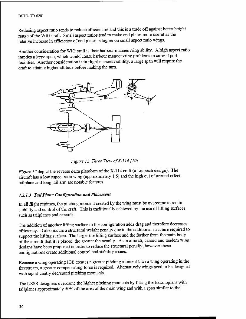
DSTO-GD-0201
Reducing aspect ratio tends to reduce efficiencies and this is a trade off against better height range of the WIG craft. Small aspect ratios tend to make end plates more useful as the relative increase in efficiency of end plates is higher on small aspect ratio wings.
Another consideration for WIG craft is their harbour manoeuvring ability. A high aspect ratio implies a large span, which would cause harbour manoeuvring problems in current port facilities. Another consideration is in flight manoeuvrability, a large span will require the craft to attain a higher altitude before making the turn.
Figure 12 Three View ofX-114 [10]
Figure 12 depict the reverse delta planform of the X-l 14 craft (a Lippisch design). The aircraft has a low aspect ratio wing (approximately 1.5) and the high out of ground effect tailplane and long tail arm are notable features.
4.2.1.3 Tail Plane Configuration and Placement
In all flight regimes, the pitching moment created by the wing must be overcome to retain stability and control of the craft. This is traditionally achieved by the use of lifting surfaces such as tailplanes and canards.
The addition of another lifting surface to the configuration adds drag and therefore decreases efficiency. It also incurs a structural weight penalty due to the additional structure required to support the lifting surface. The larger the lifting surface and the further from the main body of the aircraft that it is placed, the greater the penalty. As in aircraft, canard and tandem wing designs have been proposed in order to reduce the structural penalty, however these configurations create additional control and stability issues.
Because a wing operating IGE creates a greater pitching moment than a wing operating in the freestream, a greater compensating force is required. Alternatively wings need to be designed with significantly decreased pitching moments.
The USSR designers overcame the higher pitching moments by fitting the Ekranoplans with tailplanes approximately 50% of the area of the main wing and with a span similar to the
34
DSTO-GD-0201
wing. This compares to an aircraft tailplane, which may typically be 15-25% of the area of a main wing. The Ekranoplan tailplanes were also mounted out of ground effect so that the aerodynamic characteristics of the tailplane did not alter with the height of the Ekranoplan above the surface. Both the size of the tailplane and its mounting high above the craft carry heavy efficiency penalties.
4.2.1.4 Engine Placement and Selection
The type and placement of engines is a major factor when considering the operational performance of a WIG craft. The take off phase is the most critical for thrust production and usually governs the placement, number and size of the engines.
If PAR technology is to be utilised, forward mounted engines with some degree of thrust vectoring will most likely be used. Similar technologies have been developed to improve the manoeuvrability of jet fighter aircraft and could possibly be adapted to WIG use.
The type of engines used will be determined by the speed of the aircraft and the quantity of thrust required. The common aviation engines such as turbo prop, jet and piston engines are the most likely to be used in WIG craft, though some design modifications may be required to provide better efficiency in the particular operating environment. The ability to service and maintain the engines in a marine environment is also a consideration in engine choice.
The use of different types of engines in aircraft operation is normally governed by the efficiency of weight to thrust and velocity to fuel consumption. Traditionally, piston engines are used for the low power, low speed, low altitude environment, with turbo prop engines used for higher power requirements at moderate speeds. At high speeds, jet engines are the most efficient with a high thrust to weight ratio and a low drag compared to propeller engines.
4.2.1.5 Control and Manoeuvrability
The manoeuvrability of WIG craft operating IGE is limited. Operating IGE, WIG craft are required to perform skidding turns due to the inability to bank the craft. This results in a very high turn radius or alternatively, the requirement to slow to displacement speeds to effect a turn. Skidding turns are also uncomfortable for personnel in the craft.
Craft that have the capability to 'zoom turn', that is to manoeuvre OGE, can make banked turns. This allows the aircraft to be balanced in all three axes and the turn radius would be similar to that of an equivalent aircraft [17]. The ability to turn is also dependent on the control power available to the craft.
The use of thrust vectoring has been investigated in order to provide greater manoeuvrability. Aircraft control systems will assist in controlling the craft, but still rely on the vehicle having sufficient control power.
4.2.2 Design Parameters: Seaborne Performance
Any WIG vehicle that operates in water needs to be designed to be sea worthy. The operational phases, which require an element of seaworthiness are take off, landing, drifting
35

DSTO-GD-0201
and low speed manoeuvring. The major design considerations for seaborne performance are the hull design, take off aids, gross dimensions and propulsion.
4.2.2.1 Takeoff
Take off distances for any craft operating from water tend to be higher than those operating from land. This is due to the high drag of the hull initially acting as a displacement vessel. This in turn leads to the time taken to reach the take off speed increasing and thus the take off distance extending.
The more critical penalty in taking off from water is the carriage of excess thrust. To overcome the drag of the water, a considerable amount of thrust is required that is not utilised in the cruise condition.
A number of methods have been proposed to reduce the take offloads and improve the take off performance of WIG craft. The use of hydrofoils, partial hovercraft technology, PAR, and other associated power augmentation methods have been proposed. The potential advantages are lower structural weights, increased sea worthiness at take off and landing and a lowering of the take off thrust.
In aircraft, flaps and other aerodynamic devices are used to increase the maximum lift of the wing so that take off can be achieved at lower speeds. Further research may find uses for these devices on WIG craft also.
The limitations associated with taking off in various wave states are discussed in Section 4.4.1.
4.2.2.2 Cruise
In cruise operations contact between the craft and the water surface is generally avoided in order to avoid the high structural loads associated with contact at high speed. Depending on the operational limitations placed on the craft, this may necessitate the use of wave detection and vertical height instruments. In turns and other manoeuvres climbing to altitude is normally used in order to avoid contact with the surface.
4.2.2.3 Landing
The performance and loads experienced in landing are not as critical as those for take off. However, a number of proposals have been put forward, aimed at reducing the loads and increasing the speed at which a safe landing may be made. Hydrodynamic skis and hydrofoils have been tested, with an observed lowering of impact loads in heavy sea states. The use of these devices is intended to slow the craft at a decreased rate, thus reducing hull loads.
The use of a hydrofoil resulted in the destruction of the X-l 14 WIG craft [10]. The aircraft was landed at too high a speed and therefore at a lower than normal angle of incidence. The fixed hydrofoil entered the water at a negative incidence, resulting in a downward force drawing the craft into the water.
36
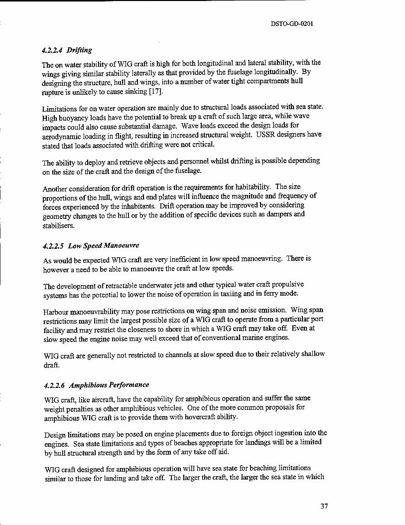
DSTO-GD-0201
4.2.2.4 Drifting
The on water stability of WIG craft is high for both longitudinal and lateral stability, with the wings giving similar stability laterally as that provided by the fuselage longitudinally. By designing the structure, hull and wings, into a number of water tight compartments hull rupture is unlikely to cause sinking [17].
Limitations for on water operation are mainly due to structural loads associated with sea state. High buoyancy loads have the potential to break up a craft of such large area, while wave impacts could also cause substantial damage. Wave loads exceed the design loads for aerodynamic loading in flight, resulting in increased structural weight. USSR designers have stated that loads associated with drifting were not critical.
The ability to deploy and retrieve objects and personnel whilst drifting is possible depending on the size of the craft and the design of the fuselage.
Another consideration for drift operation is the requirements for habitability. The size proportions of the hull, wings and end plates will influence the magnitude and frequency of forces experienced by the inhabitants. Drift operation may be improved by considering geometry changes to the hull or by the addition of specific devices such as dampers and stabilisers.
4.2.2.5 Low Speed Manoeuvre
As would be expected WIG craft are very inefficient in low speed manoeuvring. There is however a need to be able to manoeuvre the craft at low speeds.
The development of retractable underwater jets and other typical water craft propulsive systems has the potential to lower the noise of operation in taxiing and in ferry mode.
Harbour manoeuvrability may pose restrictions on wing span and noise emission. Wing span restrictions may limit the largest possible size of a WIG craft to operate from a particular port facility and may restrict the closeness to shore in which a WIG craft may take off. Even at slow speed the engine noise may well exceed that of conventional marine engines.
WIG craft are generally not restricted to channels at slow speed due to their relatively shallow draft.
4.2.2.6 Amphibious Performance
WIG craft, like aircraft, have the capability for amphibious operation and suffer the same weight penalties as other amphibious vehicles. One of the more common proposals for amphibious WIG craft is to provide them with hovercraft ability.
Design limitations may be posed on engine placements due to foreign object ingestion into the engines. Sea state limitations and types of beaches appropriate for landings will be a limited by hull structural strength and by the form of any take off aid.
WIG craft designed for amphibious operation will have sea state for beaching limitations similar to those for landing and take off. The larger the craft, the larger the sea state in which
37
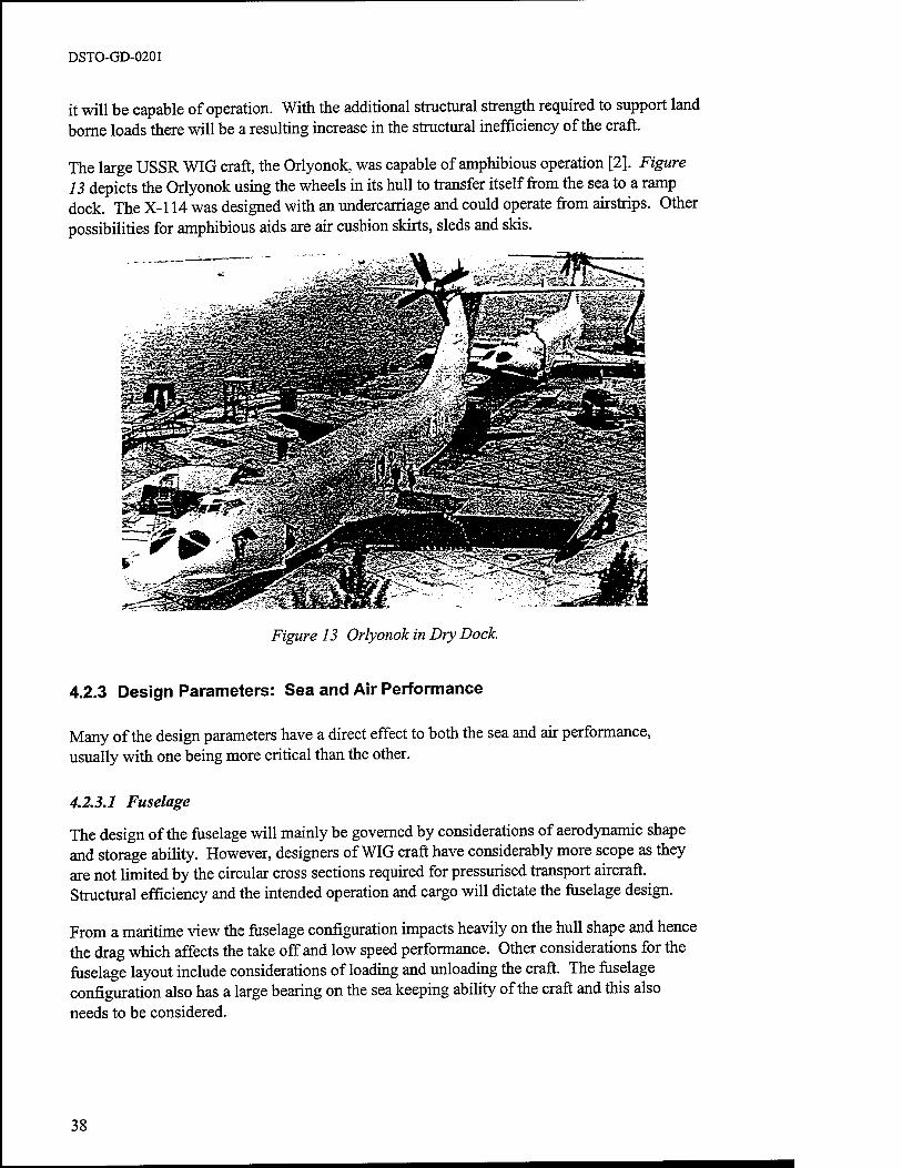
DSTO-GD-0201
it will be capable of operation. With the additional structural strength required to support land borne loads there will be a resulting increase in the structural inefficiency of the craft.
The large USSR WIG craft, the Orlyonok, was capable of amphibious operation [2]. Figure 13 depicts the Orlyonok using the wheels in its hull to transfer itself from the sea to a ramp dock. The X-l 14 was designed with an undercarriage and could operate from airstrips. Other possibilities for amphibious aids are air cushion skirts, sleds and skis.
Figure 13 Orlyonok in Dry Dock.
4.2.3 Design Parameters: Sea and Air Performance
Many of the design parameters have a direct effect to both the sea and air performance, usually with one being more critical than the other.
4.2.3.1 Fuselage
The design of the fuselage will mainly be governed by considerations of aerodynamic shape and storage ability. However, designers of WIG craft have considerably more scope as they are not limited by the circular cross sections required for pressurised transport aircraft. Structural efficiency and the intended operation and cargo will dictate the fuselage design.
From a maritime view the fuselage configuration impacts heavily on the hull shape and hence the drag which affects the take off and low speed performance. Other considerations for the fuselage layout include considerations of loading and unloading the craft. The fuselage configuration also has a large bearing on the sea keeping ability of the craft and this also needs to be considered.
38

DSTO-GD-0201
4.2.3.2 Survivability
Crashworthiness and survivability have grown increasingly important in aviation circles in recent time and would most likely be considered in any WIG design.
The civilian aviation standards provide a working basis for the inclusion of these provisions in WIG craft. These standards consider crashworthiness, survival equipment and evacuation from the craft. The implications on the craft's performance of these types of crashworthiness requirements would be no more severe than for aircraft or helicopters.
The weight penalty incurred by the provision for fire fighting and mechanical repair, as occurs on ships would be excessive on WIG craft.
Stealth through the integration of IR, radar and noise reduction technologies are areas that would increase the survivability of a WIG craft in a combat situation. The propulsive means (jet, turbine or piston engine) will define the methods and possibilities for reduction of the IR signature. Nozzle mixing and other methods are areas of current research in the reduction of IR signatures. The use of composite and other stealth enhancing materials could be considered. The likely performance degradations for use of stealth technology are similar to those of aircraft.
WIG craft have the added advantage of operating near the earth's surface providing low radar detectability.
4.2.3.3 Mother Ship Operation
Small WIG craft could be operated from ships with the WIG craft lifted onto the deck of the ship. The main limitation to such an operation would be the sea state limitation of the small WIG craft.
39
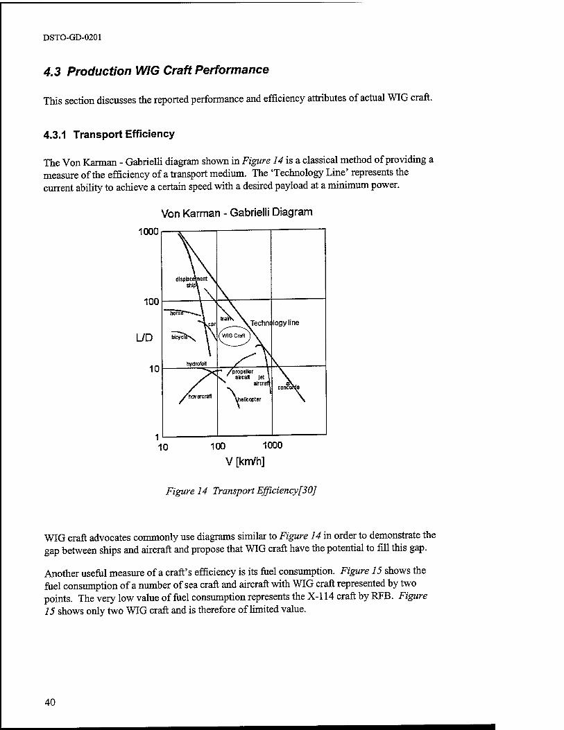
DSTO-GD-0201
4.3 Production WIG Craft Performance
This section discusses the reported performance and efficiency attributes of actual WIG craft.
4.3.1 Transport Efficiency
The Von Karman - Gabrielli diagram shown in Figure 14 is a classical method of providing a measure of the efficiency of a transport medium. The 'Technology Line' represents the current ability to achieve a certain speed with a desired payload at a minimum power.
Von Karman - Gabrielli Diagram
1000
10 100 1000
V [km/h]
Figure 14 Transport Efficiency[30]
WIG craft advocates commonly use diagrams similar to Figure 14 in order to demonstrate the gap between ships and aircraft and propose that WIG craft have the potential to fill this gap.
Another useful measure of a craft's efficiency is its fuel consumption. Figure 15 shows the fuel consumption of a number of sea craft and aircraft with WIG craft represented by two points. The very low value of fuel consumption represents the X-l 14 craft by RFB. Figure 15 shows only two WIG craft and is therefore of limited value.
40
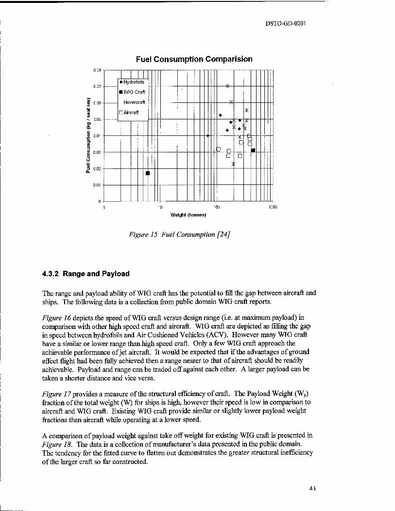
DSTO-GD-0201
Fuel Consumption Comparision 0.08
0.07
J 0.06
- 0.05
.2 0.04 Q. £ 3 |2 0.03 o o
3 0.02 U.
0.01
♦■ Hydrofoils
■ WIGCral
Hovercral
U Aircraft
t
Y
♦ X
3 n D
tl a
m D D
II
10 100
Weight (tonnes)
1000
Figure 15 Fuel Consumption [24]
4.3.2 Range and Payload
The range and payload ability of WIG craft has the potential to fill the gap between aircraft and ships. The following data is a collection from public domain WIG craft reports.
Figure 16 depicts the speed of WIG craft versus design range (i.e. at maximum payload) in comparison with other high speed craft and aircraft. WIG craft are depicted as rilling the gap in speed between hydrofoils and Air Cushioned Vehicles (ACV). However many WIG craft have a similar or lower range than high speed craft. Only a few WIG craft approach the achievable performance of jet aircraft. It would be expected that if the advantages of ground effect flight had been fully achieved then a range nearer to that of aircraft should be readily achievable. Payload and range can be traded off against each other. A larger payload can be taken a shorter distance and vice versa.
Figure 17 provides a measure of the structural efficiency of craft. The Payload Weight (Wp) fraction of the total weight (W) for ships is high, however their speed is low in comparison to aircraft and WIG craft. Existing WIG craft provide similar or slightly lower payload weight fractions than aircraft while operating at a lower speed.
A comparison of payload weight against take off weight for existing WIG craft is presented in Figure 18. The data is a collection of manufacturer's data presented in the public domain. The tendency for the fitted curve to flatten out demonstrates the greater structural inefficiency of the larger craft so far constructed.
41
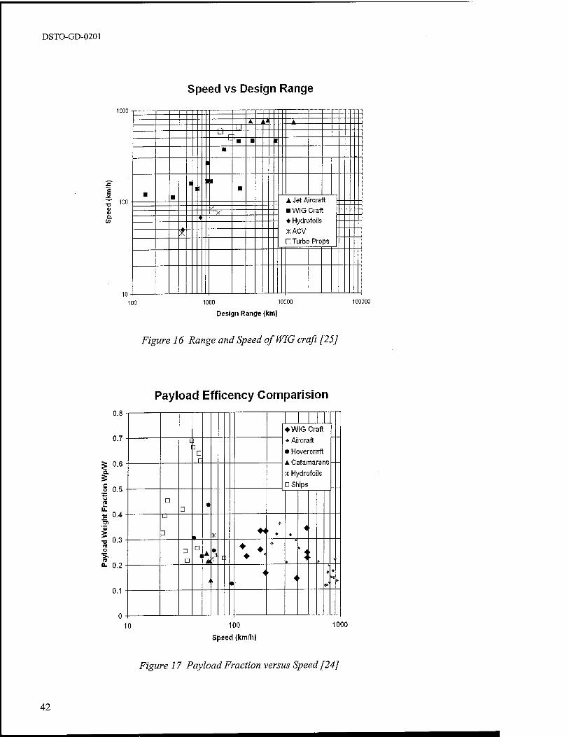
DSTO-GD-0201
Speed vs Design Range
1000
T3 <U <u a. CO
100
10
A. (J A 1 1 u
r '■ m ■ ■
1
■ ■ 1
1 II
■ - A. Jet Aircraft - ■ WIG Craft - ♦ Hydrofoils
XACV D Turbo Props
V "SJC
4
*
100 1000 10000
Design Range (km)
100000
Figure 16 Range and Speed of WIG craft [25]
Payload Efficency Comparision 0.8
0.7
g 0.6 Q.
o 0.5
u. £ 0.4
'3
■c 0-3 5 o
n- 0.2
0.1
♦ WIG Craft
♦ Aircraft
♦ Hovercraft A Catamarans --
x Hydrofoils
a Ships
C ] 1 □ r
□ D
• Ü
D t X
♦< > * * 4 ■
□ D
D
M
• c ] ♦♦♦.
^
&- * 4
4 ►
.
i i 1
4 i
► 4
**
10 100
Speed (km/h)
1000
Figure 17 Payload Fraction versus Speed [24]
42
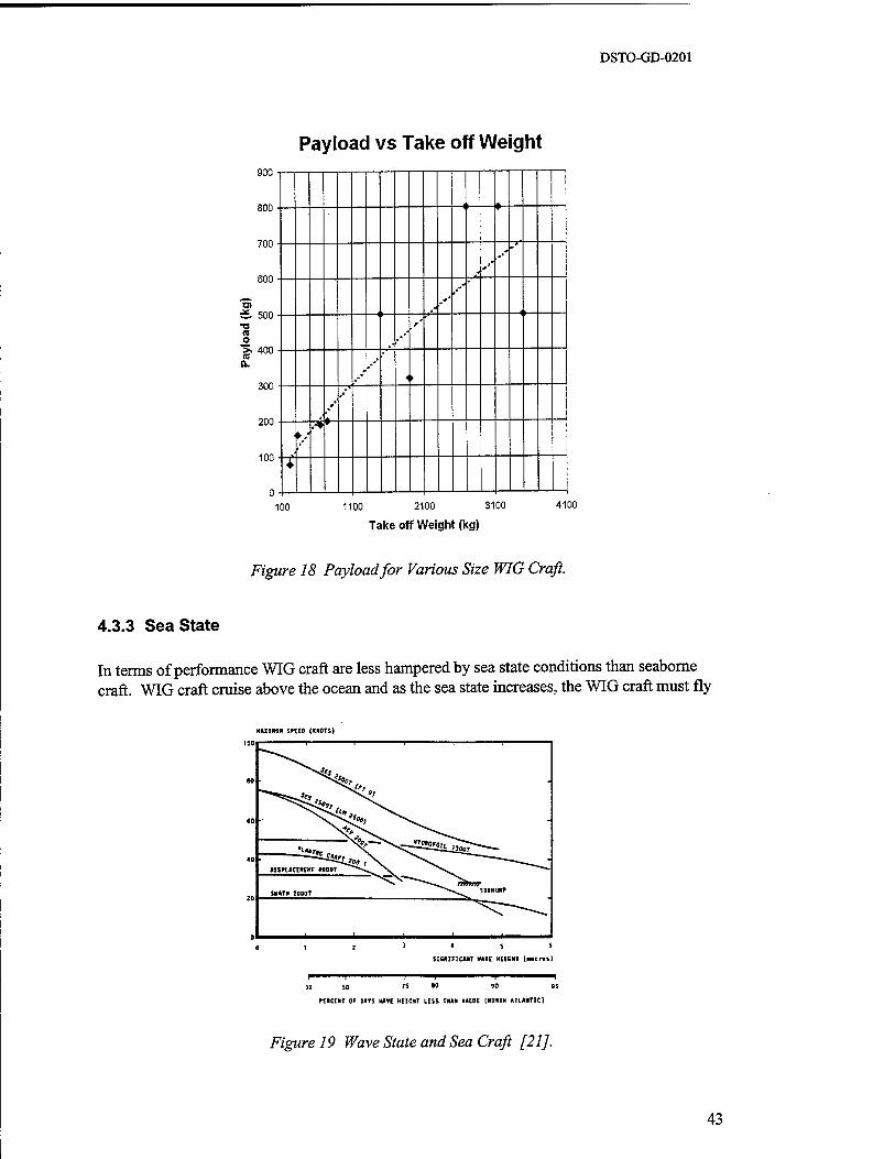
DSTO-GD-0201
Payload vs Take off Weight 900
800
700
600
& 500 ■o a o >. 400 0.
300
200
100
1! *
1, -^ IP
,-"' <►
: * -^
/
100 1100 2100 3100
Take off Weight (kg)
4100
Figure 18 Payload for Various Size WIG Craft.
4.3.3 Sea State
In terms of performance WIG craft are less hampered by sea state conditions than seaborne craft. WIG craft cruise above the ocean and as the sea state increases, the WIG craft must fly
MUM* SHE» (HOTS)
^^S^r;
SUIKIM»
_^_- OlSPLACEItEIT MOOT ^~~^ \
SWATH 2000T
SKaiFICMT »ATE HEICHT («.tr.ll
90 SO »5 0°
fERCERT OF UTS HAVE HEIGHT LESS THAN VALUE (MOUTH ATLANTIC]
Figure 19 Wave State and Sea Craft [21].
43
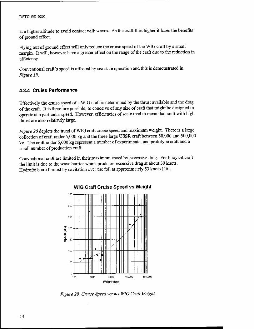
DSTO-GD-0201
at a higher altitude to avoid contact with waves. As the craft flies higher it loses the benefits of ground effect.
Flying out of ground effect will only reduce the cruise speed of the WIG craft by a small margin. It will, however have a greater effect on the range of the craft due to the reduction in efficiency.
Conventional craft's speed is affected by sea state operation and this is demonstrated in Figure 19.
4.3.4 Cruise Performance
Effectively the cruise speed of a WIG craft is determined by the thrust available and the drag of the craft. It is therefore possible, to conceive of any size of craft that might be designed to operate at a particular speed. However, efficiencies of scale tend to mean that craft with high thrust are also relatively large.
Figure 20 depicts the trend of WIG craft cruise speed and maximum weight. There is a large collection of craft under 5,000 kg and the three large USSR craft between 50,000 and 500,000 kg. The craft under 5,000 kg represent a number of experimental and prototype craft and a small number of production craft.
Conventional craft are limited in their maximum speed by excessive drag. For buoyant craft the limit is due to the wave barrier which produces excessive drag at about 30 knots. Hydrofoils are limited by cavitation over the foil at approximately 53 knots [26].
WIG Craft Cruise Speed vs Weight 350
300
250
S> 200
100
50
A
V
♦
,.'■
' ► M"l
100 1000 10000 100000 1000000
Weight (kg)
Figure 20 Cruise Speed versus WIG Craft Weight.
44
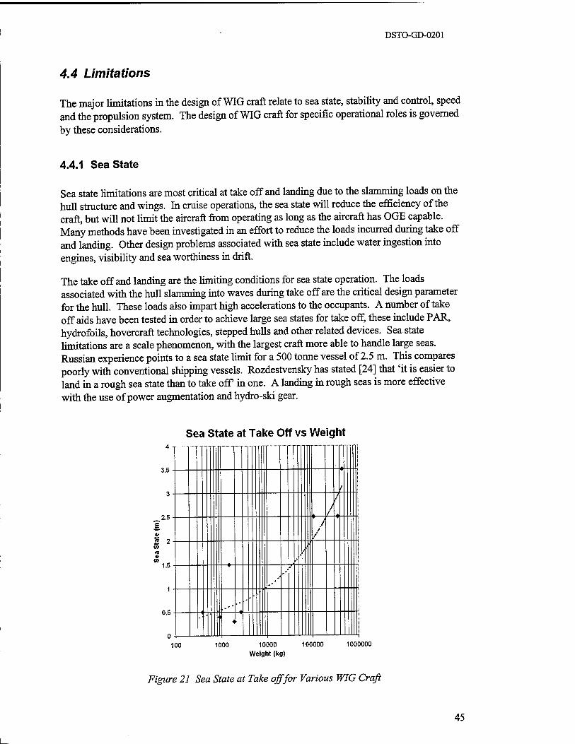
DSTO-GD-0201
4.4 Limitations
The major limitations in the design of WIG craft relate to sea state, stability and control, speed and the propulsion system. The design of WIG craft for specific operational roles is governed by these considerations.
4.4.1 Sea State
Sea state limitations are most critical at take off and landing due to the slamming loads on the hull structure and wings. In cruise operations, the sea state will reduce the efficiency of the craft, but will not limit the aircraft from operating as long as the aircraft has OGE capable. Many methods have been investigated in an effort to reduce the loads incurred during take off and landing. Other design problems associated with sea state include water ingestion into engines, visibility and sea worthiness in drift.
The take off and landing are the limiting conditions for sea state operation. The loads associated with the hull slamming into waves during take off are the critical design parameter for the hull. These loads also impart high accelerations to the occupants. A number of take off aids have been tested in order to achieve large sea states for take off, these include PAR, hydrofoils, hovercraft technologies, stepped hulls and other related devices. Sea state limitations are a scale phenomenon, with the largest craft more able to handle large seas. Russian experience points to a sea state limit for a 500 tonne vessel of 2.5 m. This compares poorly with conventional shipping vessels. Rozdestvensky has stated [24] that 'it is easier to land in a rough sea state than to take off in one. A landing in rough seas is more effective with the use of power augmentation and hydro-ski gear.
Sea State at Take Off vs Weight
3.5
2.5
« 2
«s w
1.5
0.5
-1 -!- t 7 J
1 /
t •'j .'
_,.- . '
1
J 100 1000 10000 100000 1000000
Weight (kg)
Figure 21 Sea State at Take off for Various WIG Craft
45
DSTO-GD-0201
WIG craft capable of OGE flight are not limited by sea state once in cruise operation. The result of having to fly at a higher altitude is loss in efficiency. However, a small WIG craft operating on open seas would be required to operate OGE too often to make the operation viable. Therefore open sea operations are, for practical purposes, limited to larger vessels.
The cruise height limitation on WIG craft is approximately 10% to 30% of cord. At higher heights the theoretical efficiency is reduced to that of an aircraft. The USSR operational experience has defined a safe operating height in terms of wave heights, where:
h = Hy£ + 0.l-c
'h' is the vertical height measured from the mean wave height, and H3% = 1.54 HI/3, where H1/3
is the significant wave height (the average of the 1/3 highest wave). When this height exceeds the ground effect height the craft is now operating as an aircraft, but generally at a lower degree of efficiency.
This formula can be used to demonstrate the usefulness of WIG craft in various sea states. For example using this formula, the Strizh (1630 kg) could potentially operate efficiently in sea states up to 0.5 metre significant wave height, whereas the Orlyonok (120 tonne) could potentially operate efficiently in sea states up to 2.6 metres.
The chance of wave impact at high speed needs to be minimised. Operation at the 3% wave height was recommended by Russian operation. This would point to operation of large craft being more beneficial as optimum cruise height is dependent on the size of the craft. Rogue wave heights can be as much as four time the mean wave height. As a result, the craft would need to have strict operational limitations to prevent it from encountering such waves or be designed to survive a wave impact. A thick hull and increased structural strength capable of taking the impact loads along with a sophisticated control system to keep the craft air borne might be necessary. Alternatively, a detection system that allowed the aircraft to measure height and sea state and enable the setting of a minimum safe operating altitude for the sea condition could be used. A combination of the two requirements would offer safe operation in cruise flight.
The use of PAR technology to reduce take offloads speed and distance posses a difficult problem in heavy sea states. Water ingestion into the forward engines becomes more common. As a result, corrosion and other performance aspects relating to the engine become a more significant design criterion. Kirillovikh of the USSR Navy has cited [17] water ingestion as a major problem that needs careful design.
4.4.2 Stability and Control
Stability and control appear to have been the major technical hurdles in the development of WIG craft. The current state of the art in this field in aeronautics has progressed to a very sophisticated stage where stability should not be a limitation on the design of WIG craft. Control is also an area where the state of the art should be relatively easily adapted to WIG craft.
46
DSTO-GD-0201
The vertical height stability of WIG craft has been demonstrated. The crux of the stability problem has been that of longitudinal dynamic stability. Designs typically have a height region where they are unstable. To negate this problem some designs have been limited in control power so that they are unable to operate in this unstable height region.
Stability over a wavy surface such as water has been another area of concern. Theoretical studies, such as those by Rozhdestvensky [25], and practical experience has shown that resonant behaviour over waves is not a critical parameter. The wave height at resonance will typically be greater than the efficient range of ground effect height.
The limitations on manoeuvrability are similar to those for stability. The large USSR WIG craft had a flat turning rate of 2.5 deg/sec [1]. For a small craft like the Amphistar, a turn radius of approximately 500 m [27] operating IGE is achievable. The Volga craft has to slow considerably in order to make a tight turn, and practically lands to make the manoeuvre.
WIG craft appear to be more inherently stable in roll than aircraft. As one wing descends, the decreased clearance increases the lift on that wing. This causes the craft to right itself [27].
4.4.3 OGE Operation
WIG craft capable of OGE operation, have no specific operational height limitation. However, operation OGE is likely to be particularly inefficient.
4.4.4 Speed
WIG craft are capable of cruise operation and slow displacement operation. They are however, limited in their ability to travel at speeds between the normal displacement speed and the stall speed of the craft. These speeds are traversed during landing and take off, but are not used consistently.
4.4.4.1 Takeoff
Take off represents the greatest performance restrictions placed on WIG craft. It limits their ability to operate in different sea states and affects the installed power required for flight.
The hydrodynamic drag of WIG craft is similar to that of seaplanes. The hydrodynamic drag for WIG craft can be broken down into the following categories.
• Hull - the normal hydrodynamic drag of the hull.
• Wings - the hydrodynamic drag of the wings in contact with the water.
• Spray - the generation of a large amount of spray from the hull and the engines.
• Endplates - the hydrodynamic drag of the endplates.
All of these factors are functions of the draft and trim of the craft and have different contributions with speed.
47
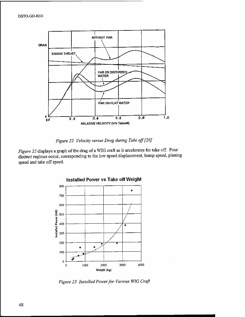
DSTO-GD-0201
DRAG
0.4 0.6 RELATIVE VELOCITY (V/V Takeoff)
Figure 22 Velocity versus Drag during Take off [20]
Figure 22 displays a graph of the drag of a WIG craft as it accelerates for take off. Four distinct regimes occur, corresponding to the low speed displacement, hump speed, planing speed and take off speed.
Installed Power vs Take off Weight 800
700
600
500
400
% 300
200
100
1
*
♦^ *
1000 2000 3000
Weight (kg)
4000
Figure 23 Installed Power for Various WIG Craft
48
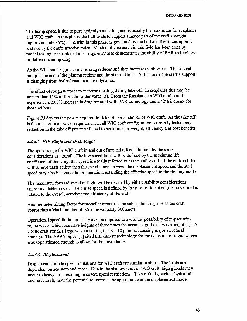
DSTO-GD-0201
The hump speed is due to pure hydrodynamic drag and is usually the maximum for seaplanes and WIG craft. In this phase, the hull tends to support a major part of the craft's weight (approximately 85%). The trim in this phase is governed by the hull and the forces upon it and not by the crafts aerodynamics. Much of the research in this field has been done by model testing for seaplane hulls. Figure 22 also demonstrates the ability of PAR technology to flatten the hump drag.
As the WIG craft begins to plane, drag reduces and then increases with speed. The second hump is the end of the planing regime and the start of flight. At this point the craft's support is changing from hydrodynamic to aerodynamic.
The effect of rough water is to increase the drag during take off. In seaplanes this may be greater than 15% of the calm water value [3]. From the Russian data WIG craft could experience a 23.5% increase in drag for craft with PAR technology and a 42% increase for those without.
Figure 23 depicts the power required for take off for a number of WIG craft. As the take off is the most critical power requirement in all WIG craft configurations currently tested, any reduction in the take off power will lead to performance, weight, efficiency and cost benefits.
4.4.4.2 IGE Flight and OGE Flight
The speed range for WIG craft in and out of ground effect is limited by the same considerations as aircraft. The low speed limit will be defined by the maximum lift coefficient of the wing, this speed is usually referred to as the stall speed. If the craft is fitted with a hovercraft ability then the speed range between the displacement speed and the stall speed may also be available for operation, extending the effective speed in the floating mode.
The maximum forward speed in flight will be defined by either; stability considerations and/or available power. The cruise speed is defined by the most efficient engine power and is related to the overall aerodynamic efficiency of the craft.
Another determining factor for propeller aircraft is the substantial drag rise as the craft approaches a Mach number of 0.5 approximately 300 knots.
Operational speed limitations may also be imposed to avoid the possibility of impact with rogue waves which can have heights of three times the normal significant wave height [1]. A USSR craft struck a large wave resulting in a 8 - 10 g impact causing major structural damage. The ARPA report [1] cited that current technology for the detection of rogue waves was sophisticated enough to allow for their avoidance.
4.4.4.3 Displacement
Displacement mode speed limitations for WIG craft are similar to ships. The loads are dependent on sea state and speed. Due to the shallow draft of WIG craft, high g loads may occur in heavy seas resulting in severe speed restrictions. Take off aids, such as hydrofoils and hovercraft, have the potential to increase the speed range in the displacement mode.
49
DSTO-GD-0201
4.4.5 Propulsion
The need for high thrust at take off has favoured low bypass ratio turbine engines on the larger craft. Propeller engines have been utilised on the smaller craft with some craft also including small marine engines for displacement movement.
The major limitations on propulsion systems are; corrosion resistance in marine environments, high thrust levels for the take off mode, fuel consumption in cruise and noise emission levels externally and internally.
The main factor determining the propulsive requirements is the thrust required on take off. Once in cruise flight, the power requirements are considerably lower. The thrust needed to take the craft from the water to the air can be prohibitive. Many solutions have been proposed including RAM-WIG technology and hybrid platforms using hovercraft and hydrofoil technologies for the initial water borne stage to reduce the required power. These technologies will be discussed in more detail in Section 7.
The engines also need to be able to withstand highly corrosive environments and the likelihood of water ingestion. Another consideration is the build up of salt deposits on blades and on the lining of the compressor and fan. The salt deposits have been demonstrated to alter the profile of the blades and alter the flow through the compressor, which has resulted in compressor stall. This is a potentially serious phenomenon, which results in a loss of power and possible flame out and can cause mechanical failure of the engine. Experience with aircraft operating in marine environments has resulted in engine washes on a regular basis to remove salt build up in the engine.
Turbine engines do not display the same efficiencies at sea level as they do at high altitude. At altitude the lower inlet temperature allows for a higher temperature rise through the engine, as the exit temperature is fixed by the turbine material properties. At sea level, the temperature rise is reduced, thus lowering the efficiency. There are many turbine engines designed for sea level use which have a high degree of efficiency, such as marine turbines.
The noise emission of WIG aircraft will be much more similar to aircraft than conventional sea craft.
50
DSTO-GD-0201
4.5 Regulation
Currently there are a few small manufacturers of WIG craft. None have gone into large scale commercial manufacture and no COTS solution currently exists. A considerable degree of design and development would be needed to obtain a new WIG craft.
The regulation of these craft is relatively untested. While the use of WIG craft in a military situation would mean that the military can essentially set their own rules, there has been a move by military organisations toward the use of civil regulations. The following information is therefore provided to give an indication of the issues that would be likely to arise with the introduction of WIG craft into military service.
The major difficulty with the regulation of WIG craft has been the confusion as to whether they ought to be considered as aircraft or sea vessel. In a recent decision, the International Civil Aviation Organisation (ICAO) and the International Maritime Organisation (MO) agreed that WIG craft should come under the jurisdiction of the MO. However, any WIG craft that is capable of sustained OGE operation will still be classified as an aircraft and comes under the jurisdiction of ICAO.
The MO has foreseen the need for a separate code for WIG craft. The perceived safety requirements fall outside those for conventional craft. A code much like the High Speed Craft (HSC) Code would need to be devised. The certification would need to be dependent on the type of class of WIG craft, with B and C class craft needing to conform to some part of the civil aviation requirements.
The Australian Maritime Safety Authority (AMSA) is the Australian body that oversees regulation of interstate and overseas marine craft in Australia. At this time it has not put in place a final decision on how to regulate repairs, modifications or maintenance of WIG craft. Similar restrictions as aircraft appear unlikely due to the heavy cost of such regulation and a self regulating industry approach is being considered.
4.5.1 Design and Construction of a New WIG
There are no current WIG craft regulations or design standards. For the design and construction of a WIG craft in the current context, the manufacturer would be writing many of the rules for the design and the safety standards as part of the certification of the craft. For civil certification, a considerable amount of collaboration with the AMSA would be required.
4.5.2 Design Standards
At present, there are no dedicated design standards for WIG craft. Proposed design standards usually involve a combination of aircraft and ship standards.
This combination usually takes the form of most of the aircraft standard with additions for seaworthiness and safety equipment. With some craft capable of autonomous operation for 3 days and the expected high level of survivability from an accident, safety provisions similar to shipping would be required. The aircraft like requirements for structural design with the
51
DSTO-GD-0201
addition of shipping requirements for seaworthiness would allow higher payload to all up weight fractions than achieved in the first generation Ekranoplans.
The implementation of a specific design standard poses some problems for WIG craft design. WIG craft have an extremely open range for possible operation and their design envelope may encompass a large number of operational types. Therefore, defined rules of a design standard may be overly restrictive and limiting for WIG craft design in terms of finding their niche market.
4.5.3 Certification Requirements
The MO has recently formulated requirements for other High Speed Craft. This covers the design and operation of hovercraft, hydrofoils and high speed catamarans. The requirements of this code are not totally acceptable for the design of WIG craft.
In Australia, a number of small manufactures have attempted to proceed through the design and certification process. However, no WIG craft has been certified for commercial operation in Australia. In order to certify these craft for commercial operation the AMS A has devised a regulatory process using a Safety Case Approach.
4.5.3.1 Current Requirements
The current requirements are still to be completely tested. The AMSA has had a number of enquiries into the design and operation of WIG craft as ferries and transport craft and is responsible for the certification of interstate and overseas travelling vessels. Vessels operating intrastate are the responsibility of the local State Authorities.
The AMSA has defined a system by which WIG craft will be certified and operated. This system is based on the 'Safety Case Approach'.
A Safety Case is defined as:
'...a documented body of evidence that provides a convincing and valid argument that the system is adequately safe for a given application in a given environment.'
In the initial cases, WIG craft will be certified for operation in a particular area, for a particular role and for particular modes. The safety aspects to be imposed will be specific to these parameters. This means that the regulation is very dependent on the operation and allows the designer some degree of flexibility in the design process.
Operational restrictions are also an important part of AMSA's approval procedure. An operator will be given approval to operate these craft on a specific route. Crew will require type approval to the craft and on the route the craft is allowed to operate.
One of the major design considerations in this case is the craft's ability to survive a forced landing after a system failure in varying sea conditions. The requirements will be dependent on the type of operation and the sea state conditions that can be expected in the location of operation.
52

DSTO-GD-0201
4.5.3.2 Military Requirements versus Civil Requirements
Current military practice in the maritime field has been to design to U.S. military standards. For aircraft, the design standards have been moving away from military standards towards civilian standards with exemptions and additional requirements for military application.
The AMSA has no regulatory authority over military craft. It should be noted that due to the high speed of WIG craft, interaction of a military WIG craft with civilian shipping needs due care. Avoidance and navigation need to be the responsibility of the WIG craft pilot. Harbour regulations and take off and landing provisions need to also be considered. These are all issues that need further investigation and determination.
53
DSTO-GD-0201
5 OPERATION
The ability for WIG craft to perform specific missions has been demonstrated in a number of select cases. Many studies ([9], [17], [24], [11], [21], [1]) have been conducted into the ability of WIG craft to fulfil specific operations ranging from heavy lift to amphibious assault.
The possible benefits from the use of these craft with a potential increase in performance and efficiency over existing transport mediums has been the momentum for their development as heavy lift and cargo platforms. The following discussion represents some of the current thoughts on the possible operational environments suited to WIG craft.
5.1 Envelope
The primary mode of operation for current and envisaged WIG craft is over and in water. Allowable sea states for efficient cruise, landing and take off form the bounds of the performance envelope. Operational considerations such as speed, range and payload abilities are similar to aircraft. Amphibious potential for operation from beachheads, waterways or runways and autonomous operation at sea are also possibilities for WIG craft. WIG craft also have the potential for high stealth and weapons delivery.
The benefits from ground effect are obtained by flying close to any flat surface. The world's oceans and waterways pose the greatest potential. Large WIG craft have been successfully operated by the USSR Navy on the Caspian Sea. A number of small craft have been developed for operation on rivers and other relatively calm waterways.
Speed, range and payload abilities of WIG craft are similar to aircraft. The potentially high L/D of WIG craft corresponds to a potentially greater efficiency than aircraft while operating at speeds which are typical of, but lower than, aircraft.
Amphibious operation of WIG craft has been accomplished in both the Orlyonok and the X- 114. The Orlyonok has been demonstrated to perform beached landings and to manoeuvre on dry dock ramps under its own power. The X-l 14 was designed with a retractable undercarriage and was capable of landings on aircraft type runways. WIG craft are also capable of autonomous sea operation. With a potential ability to use high speeds to reach a location, land, perform a task and take off.
The stealth potential for WIG craft is due to their low altitude and high speed. Their low altitude reduces the effectiveness of many sensing devices.
54
DSTO-GD-0201
5.2 Current Environments
At the current time, there are no WIG craft in operation in navies around the world. There have been three craft commissioned by the Russian Navy from the 1979 to 1989 of which none are currently in operation. There has been limited production of recreational craft in Russia, Germany and the US.
The USSR Navy operated three vessels over a ten year period. These craft were designed for specific operations and as demonstrators. The Orlyonok was operated as a troop transport and assault craft while the Lun was designed as a surface to surface missile launch craft. These craft were operated on the relatively calm waters of the Caspian Sea in calm to rough weather conditions. Reputedly, theses craft have operated in seas up to 2.5 metres [20].
Jörg and a number of Russian manufacturers have designed a number of commercially available recreational craft. These craft are intended for operation on rivers and lakes in low sea states. These craft are generally class A craft and are incapable of free flight.
5.3 Possible Missions Profiles
There have been a number of studies into the mission profiles that WIG craft might fulfil. Below are some of the more noteworthy suggestions.
• Sea lift and heavy lift platforms - capable of transporting a large payload with aircraft like speed.
• Hospital and rescue craft - one of the Russian Orlyonok craft was to be refitted for this role, where its high speed capability would allow for decreased response times in case of an at sea emergency.
• Anti Submarine Warfare (ASW).
• Amphibious assault, insertion and extraction.
• Anti Surface Warfare (ASUW) - high stealth and speed are used to deliver air to surface weapons.
• Customs patrol - the WIG craft's high speed is utilised to patrol and apprehend vessels.
• Sprint and drift applications - coupled with ASW and patrol duties.
55
DSTO-GD-0201
5.4 Crew Requirements
The requirements for crew are similar to those of aircraft and helicopters. Crews would generally not be expected to perform long duration autonomous operations. Training of WIG crews will be dependent on the class of craft. With crews of Class A craft requiring less training than crews of Class B and C craft who would require training similar to aircraft crews.
Compared to sea going craft the number of crew will be substantially reduced. For civil operation, AMSA will take into consideration aircraft type crew requirements as well as those of ships. At this stage, no specific guidelines have been formed by AMSA.
5.4.1 Crew Training Requirements
The training requirements for WIG craft pilots would depend on the class of craft. For those craft of Class A, the requirements would be similar to those for hovercraft or other SES craft. For Class B craft, training would need to take in a substantial amount of aircraft type training. While Class C crew, would need to have sufficient training to operate as aircraft pilots and ship's captains in much the same way that seaplane pilots do. Experience in the USSR has shown that crews need to start on small craft and proceed to larger craft to learn effectively. USSR experience shows a crew training period of 2 - 3 months.
It is likely that the civil requirements will require crew licensing to a type of WIG craft and to an area of operation. Operators will need to be approved for the craft and the route ofthat craft. This will result in training for aircraft type operation and marine operations . However, these pilots will not be allowed to fly unless they hold a civil aviation endorsement to fly. These pilots will be under the control of the maritime authority unless the craft is capable of OGE flight, where they are under the jurisdiction of the civil aviation authority. Civil requirements will be highly restrictive while safety concerns are overcome by operational experience.
5.4.2 Crew Facilities
The on-board crew facilities will depend on the desired mission. Similar facilities as aircraft would be favoured from a structural weight viewpoint. However, if long sea endurance is envisaged then more ship type facilities would be required. This would result in an increased structural weight.
Extended autonomous operation would incur a weight penalty due to the increased weight of additional facilities. WIG craft design and efficiency are highly dependent on weight, with any increase degrading performance. The on water sea state limitations would also pose a severe restriction on autonomous operation. Due to these considerations, it is unlikely that WIG craft would be a viable option for extended autonomous operations.
56
DSTO-GD-0201
5.5 Sea Port Requirements
WIG craft have the potential to operate from current sea ports. For maintenance purposes, WIG craft would need to be removed from the water regularly. Engines need to be maintained and protected from salt water and salt in the air. These form special requirements for the maintenance and home port facilities for WIG craft.
WIG craft have the potential to be made amphibious. This allows docking on beaches, ramps or other rudimentary facilities. USSR operators commonly used a ramp as the most common method of transferring the WIG craft from the water to the land for maintenance.
WIG craft have no need for dedicated channels for their ferry operations as they have shallow drafts. The largest Russian craft of 500 tonne displacement weight had a draft of only 2.5 metres. The only possible limitation on sea port operation is the span of the craft. The small WIG craft typically have a span of 7 meters while the large USSR craft had spans as high as 45 meters. This could impose harbour manoeuvring limitations.
For on ship handling, similar procedures as were used for seaplanes in the early stages of the Second World War would be appropriate. In these operations, the WIG craft could be lowered over the side of the ship, using a crane and the crane could be used for retrieval. Storage requirements would be similar to helicopters. Folding wings have the potential to reduce deck footprints.
5.6 Maintenance Requirements
The maintenance requirements for WIG craft would most likely be higher than similarly sized aircraft. Engines and structure would require frequent washing to protect it from corrosion damage. Expected structural life cycles due to corrosion damage are 15 years [17]. Dry dock requirements may be mandatory in order to increase craft life. The craft will need regular dry- docking to perform hull cleaning and maintenance.
Major work will be needed in cleaning hulls and maintaining corrosion protection. The type of maintenance schedules and controls used on seaborne helicopters would be required for WIG craft.
5.6.1 Maintenance Cycles
The ARPA analysis for a large turbine engine powered WIG craft produced the following engine maintenance cycles estimates along with the comparison to US Navy aircraft and seaplane requirements and operational experience [2].
• Engine Replacements (ER): 0.4 to 0.9 ER per 1000 hours per engine
• Engine Maintenance Actions (EMA): 724 EMA per 1000 hours per engine
57
DSTO-GD-0201
• Engine washes daily. From seaplane experience, engines are washed daily with fresh water.
6 MANUFACTURE
Outside of Russia, there is little experience in manufacture of WIG craft. A number of organisations have worked over the last 30 years in the field and have produced small production runs. Many research organisations around the world have developed prototype craft and performed a considerable amount of testing. The Russian's have by far the most experience and the largest body of experimental data relating to WIG craft.
A design bureau would need, as a minimum, the following qualifications and experience to successfully design a WIG craft.
• aerodynamics performance prediction
• aerodynamic stability and control
• mechanical systems design
• light weight structural design
• high thrust propulsive systems e.g. piston, turbine and jet engines
• integrated systems design
• hydrodynamic design and loading prediction
• waterborne craft stability
A manufacturer of WIG craft will need to have experience and expertise in the following areas of manufacture.
• light weight structural manufacture
• aluminium and/or composite manufacture
• installation of propulsive systems and fuel tanks
• installation of radar and other high technology sensing equipment
• water tight manufacturing methods
• marine and corrosion resistant surface finish
58

DSTO-GD-0201
6.1 Manufacturing Requirements
Regulatory manufacture requirements in the civilian sphere are being investigated. It appears that regulation of maintenance of WIG craft will follow the guidelines of the high speed craft code and move more towards the civil aviation requirements in the future.
The manufacture would need processes and the ability to handle and manufacture using the desired materials. Aircraft manufacturing techniques call for a substantial investment in tooling and manufacturing processes. Composite manufacture can also require expensive manufacturing items such as kilns and tools.
6.2 Construction Time
The time for design and construction of a new WIG craft is dependent on the design specification and the experience of the design organisation.
Russian designers have had extensive experience with WIG craft of differing sizes. Amphistar took three years from design, construction and testing [28] to a limited production model. The Russian designers state that it would take three years to build a craft similar in design to previous craft, new designs could take appreciably longer. This would all be dependent on the size of the craft and the design and research requirement for the project [17].
6.3 Potential and Current Manufactures
There are a number of manufacturers who have designed and constructed prototype and production craft. There are also organisations that have conducted preliminary research and have been responsible for a number of paper designs. The following lists a number of existing manufacturers who have shown the potential to design WIG craft.
BOTEC Ingenieursozietät GmbH (Jörg) of Germany
Fischer Flugmechanik GmbH of Germany
Techno Trans e.V. of Germany
Lockheed Martin of the USA
Aerocon of the USA
FlarecraftoftheUSA
The Central Hydrofoil Design Bureau of Russia
Sukhoi of Russia
SDPP Dynamic Support Craft of Russia
59
DSTO-GD-0201
7 TECHNOLOGICAL RISK
The technology base for WIG craft design is similar in scope to that of aircraft and particularly seaplanes. It was concluded in reference [3] that there were three primary technological areas which with further research and development would significantly improve the performance of WIG craft above the early Russian designs. They are take off aids, propulsion and structures. They also cited three other areas where advancement would increase design confidence these being, modelling and simulation, sensors and actuators. It was also concluded that there where two functional areas which entail procedural changes to that of conventional craft such as ships and aircraft. These are design methodology and flight- testing.
The ARPA report also concluded that developments in aerodynamics, hydrodynamics and stability and control were not necessary. ARPA recognised that the effect of hydrodynamics on the loads associated with take off and landing need further study and this area falls into the research area of structures. The reasons for the omission of aerodynamics, hydrodynamics and stability and control as areas that do not need specific research are given by the following, from reference [3].
For the aerodynamic behaviour of WIG craft outside the take off and landing modes the following reasons were given for the adequacy of the current level of knowledge.
The steady state aerodynamics of wingships in cruise flight is now quite tractable and well understood... Empirical relations for estimating performance of wingships are not as good as conventional aircraft, however, they are adequate to estimate the sizes and proportions of craft to perform specific missions...
The unsteady aerodynamics of wingships is not well understood. This lack of development results from the fact that there is one more source of unsteadiness in the wingship case when compared to aircraft... we believe that craft designs will generally be based on steady flow aerodynamics with margins applied to cover the environments statistical nature... It does not seem that the future of wingship design rests heavily on further developments in the understanding of unsteady flow.
In regards to developments in hydrodynamics, the ARPA report viewed it as heavily dependent on the specific design and as part of the take off and landing performance.
Hydrodynamics permeates many aspects of wingship design... an essential part of take off... and structural loads. Also hydrodynamics is the key technology in achieving acceptable habitability during loiter on the sea surface, and the design methodology... incorporates habitability.
The stability and control issues associated with WIG craft have been of primary concern in the early development of WIG craft. The ARPA report found that the current understanding of control and stability to be adequate to surmount the WIG craft phenomenon. Stability and control borders on the areas of simulation, flight test and navigation sensors. Thus, investigations into these areas should adequately cover the most important aspects of stability and control. Control for unsteady aerodynamics of WIG craft is not envisaged to be more difficult than the development of the X-31, which was adequately controlled using linear augmentation and data from flight tests.
60
DSTO-GD-0201
Much of the information and analysis for this section is due to reference [3] the ARPA report "Wingship Investigation - Volume 3 - Technological Road Map". The type of WIG craft investigated by ARPA were of take off weights in the 400 to 1000 tonne range. However, the statements regarding technological issues in the ARPA report are relevant to WIG craft of small or large take off weights. This section also includes discussion from other references of various other technologies and the current state of the art developments in these areas.
7.1 Takeoff Aids
'The single greatest impediment to the overall utility is the large power required to accelerate from rest to cruise speed...'[3].
This is similar to the phenomenon experienced in aircraft, but on a greater scale. In aircraft, the excess thrust at sea level is reduced to match the drag at altitude with an increase in efficiency. However for WIG craft no such benefits are available consequently the engine thrust is excessive for cruise flight.
Take off and landing represent the peak load cases for WIG craft operation. With the interaction of the craft and the water surface under varying sea state conditions defining the maximum local hull pressure loads as well as the g loading for the rest of the structure.
The following table represents take off and landing research areas that need further research to determine their potential benefits. The technological areas listed in Table 5 are surmised to produce potential efficiency benefits for take off and landing, by decreasing take off power, speed and loading.
61
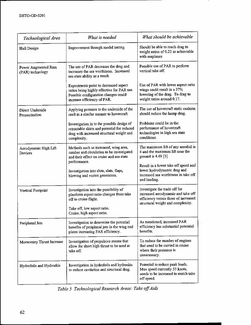
DSTO-GD-0201
Technological Area
Hull Design
Power Augmented Ram (PAR) technology
Direct Underside Pressurisation
Aerodynamic High Lift Devices
Vertical Footprint
Peripheral Jets
Momentary Thrust Increase
Hydrofoils and Hydroskis
What is needed
Improvement through model testing
The use of PAR decreases the drag and increases the sea worthiness. Increased sea state ability as a result.
Experiments point to decreased aspect ratios being highly effective for PAR use. Possible configuration changes could increase efficiency of PAR.
Applying pressure to the underside of the craft in a similar manner to hovercraft.
Investigation in to the possible design of retractable skirts and potential for reduced drag with increased structural weight and complexity.
Methods such as increased, wing area, camber and circulation to be investigated and their effect on cruise and sea state performance.
Investigation into slots, slats, flaps, blowing and vortex generators.
Investigation into the possibility of planform aspect ratio changes from take off to cruise flight.
Take off, low aspect ratio. Cruise, high aspect ratio.
Investigation to determine the potential benefits of peripheral jets in the wing end plates increasing PAR efficiency.
Investigation of propulsive means that allow for short high thrust to be used at take off.
Investigation in hydrofoils and hydroskis to reduce cavitation and structural drag.
What should be achievable
Should be able to reach drag to weight ratios of 0.23 as achievable with seaplanes
Possible use of PAR to perform vertical take off.
Use of PAR with lower aspect ratio wings could result in a 37% lowering of the drag. To drag to weight ratios around 0.17.
The use of hovercraft static cushion should reduce the hump drag.
Problems could lie in the performance of hovercraft technologies in high sea state conditions.
The maximum lift of any aerofoil is 4 and the maximum lift near the ground is 4.49 [3]
Result in a lower take off speed and lower hydrodynamic drag and increased sea worthiness in take off and landing.
Investigate the trade off for increased aerodynamic and take off efficiency versus those of increased structural weight and complexity.
As mentioned, increased PAR efficiency has substantial potential benefits.
To reduce the number of engines that need to be carried in cruise where their presence is unnecessary.
Potential to reduce peak loads. Max speed currently 55 knots, needs to be increased to match take off speed.
Table 5 Technological Research Areas: Take off Aids
62

DSTO-GD-0201
7.2 Propulsion
The propulsion system suffers from two shortcomings. Firstly, and generic to all forms of propulsion is the corrosive environment and the limitations on performance and maintenance and increased cost of operation that imposes. Secondly, is the mismatch of power for take off and for cruise flight.
Research into improving propulsion maintenance and durability has been a primary area of research in both the aviation and automotive fields. However, such engines operate in significantly more benign environments than WIG craft and only naval aircraft at sea have to deal with some degree of salt in the air.
For turbine engines, salt in the air passes into the compressor where it collects on blades and the inner surface of the engine. This alters the aerodynamic shape of blades and can precipitate compressor stall. This results in loss of power and may cause structural damage to the engine. The occurrence of stall is relatively well understood, the area for further research is in the reduction and monitoring of salt build up. By reducing the mechanism by which salt builds up on blade surfaces, an increase in the time between washes can be achieved. The monitoring of salt build up and more accurate prediction of salt deposits will increase the efficiency of engine washes.
For all types of engines, some degree of resistance to corrosion in salt water environments is necessary to reduce service cost to an acceptable level. The USSR used aircraft engines that had been specially marinised to increase their operational life. The research in increasing service life of engines will not only have a benefit for WIG craft, but marine craft in general.
The problem of thrust mismatch at take off and cruise has two possible effects on performance in cruise. The engines are forced to operate at an inefficient thrust level or some of the engines are shut down resulting in increased drag due to their windmilling. A possible solution is to devise an engine which is capable of generating a high level of thrust for a short period of time and then can operate efficiently at a lower thrust level for an extended period.
The noise emission of typical aircraft engines is high. For certain WIG craft applications, this may be unacceptable and methods for decreasing noise emission will need investigation. This is a current trend in the civil aviation industry.
Propulsion system research is important for the ongoing maintenance and the reduction in operating cost. It is not a decisive factor in the ability for a WIG craft to be designed and operated.
63
DSTO-GD-0201
7.3 Structures
Structural research and development has two major areas where research could lead to improvements in WIG craft performance and design, a better model for the determination of hydrodynamic loads and improved material properties against corrosion.
The determination of water loads affects the structural design of the hull and wing. An emphasis needs to be placed on reduced structural weight, as the weight of WIG craft is as critical as for aircraft. The ARPA report emphasised a movement towards composite skins instead of the welded steel structure of the Russian large WIG craft.
Better structural design can be achieved through better load determination. Current practice is to use model tests to predict slamming and other hydrodynamic loads. These experiments are specific to a hull design. Possible improvements in determining loads and lowering the maximum load through changes in geometry were considered by ARPA. They suggested an emphasis in the following areas:
• Experiments with hull geometry for determination and reduction of impact loads.
• Experiments with endplates to determine loading on wing structure with contact of endplates and water surface.
• Development of computer models augmented by testing, to allow for greater flexibility in design.
Another area for research with a potential to increase WIG craft performance is the integration of material with high structural strength and corrosion resistance. The use of composite materials with a thermoplastic matrix has the potential for high strength and resistance to the salt water environment. To limit impact loads and decrease the likelihood of hull rupture corrugated and cellular materials could be used. This is an area for consideration in the detailed design of WIG craft.
64
DSTO-GD-0201
7.4 Systems
Much of the research and development needed in the systems area is related to the integration of current system into WIG craft. Specific WIG craft systems can, in general, be adapted from existing systems.
7.4.1 Sensors and Navigation
The sensors and navigation systems for WIG craft involve a combination of existing sensors. The inclusion of these systems does not have the potential to increase overall efficiency of the craft but are necessary for its safe operation.
Two factors drive the WIG crafts need for special sensors, water proximity and sea state. Sea state needs to be measured to determine the safe operating altitude. The ARPA report concluded that there was no need for significant research and development for such a system. The measurement of vertical height could be done through a number of means; differential GPS, radar or sonar reflection. This is heavily linked with the determination of sea state.
The sensors needed for augmented flight control systems are similar to those in aircraft. For WIG craft there is the addition of accurate measurement of the vertical height from the surface.
Obstacle detection is important for WIG craft safety. This requires a system similar to aircraft where obstacles can be seen and tracked. The system needs to be able to detect rogue waves, small craft and other hazards pertinent to a craft operating at low altitude and high speed.
7.4.2 Actuators
Current aircraft technology should be sufficient to be applied to the specific control of WIG craft. There is no real need for research into this area, it is simply an issue of design integration.
7.4.3 Simulation and Modelling
With such a complex system, a high degree of simulation and computer modelling of the craft water and flight characteristics will be necessary in the design phase. The ARPA report states that 'Simulators are indispensable in new vehicle development' [3]. The research in this area is mainly needed to adapt existing technology to WIG craft application.
Simulators would be used to support control system development and validate manoeuvrability and control predictions. The necessary data will constitute flight and model testing to support simulation development and validate the models.
65
DSTO-GD-0201
7.5 Development
Due to the newness of WIG craft technology, a reasonable amount of research is needed into such areas as configuration design and flight testing methodologies. This research could pay substantial dividends with increases in performance.
7.5.1 Configuration Design
The need for experience in the design and optimisation process of WIG craft can not be understated. The use of aviation industry experience with special modification for specific WIG craft considerations should lead to the most beneficial results. The ARPA report emphasised research into the design methodology and the method of optimisation including optimisation of the optimisation process.
7.5.2 Flight Testing
This will be a substantial area of research into a specific design. Flight testing will need to:
• Provide information for assessment of acquisition risk,
• Verify attainment of technical performance,
• Verify systems operation, and
• Provide information in support of decision making.
66
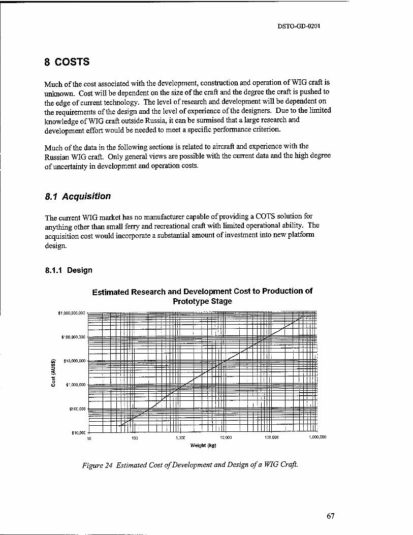
DSTO-GD-0201
8 COSTS
Much of the cost associated with the development, construction and operation of WIG craft is unknown. Cost will be dependent on the size of the craft and the degree the craft is pushed to the edge of current technology. The level of research and development will be dependent on the requirements of the design and the level of experience of the designers. Due to the limited knowledge of WIG craft outside Russia, it can be surmised that a large research and development effort would be needed to meet a specific performance criterion.
Much of the data in the following sections is related to aircraft and experience with the Russian WIG craft. Only general views are possible with the current data and the high degree of uncertainty in development and operation costs.
8.1 Acquisition
The current WIG market has no manufacturer capable of providing a COTS solution for anything other than small ferry and recreational craft with limited operational ability. The acquisition cost would incorporate a substantial amount of investment into new platform design.
8.1.1 Design
Estimated Research and Development Cost to Production of Prototype Stage
$1,000,000,000
$100,000,000
S? $10,000,000 CO
<
U $1,000,000
$100,000
$10,000
jjä /'
s s
s s »" "
v^-
s "fir ■■
100 1.000 10.000
Weight (kg)
100.000 1.000.000
Figure 24 Estimated Cost of Development and Design of a WIG Craft.
67

DSTO-GD-0201
At the current time, there would be a need for substantial investment in research and development to obtain a working and efficient WIG craft. It is assumed that the development requirements of a WIG craft would be similar to an aircraft of comparable size and weight.
Estimations based on aircraft type costing, as given in [3], have been used to produce Figure 24. The cost mainly reflects preliminary design testing and evaluation ofthat design and the detailed engineering required to start production of a prototype craft.
8.1.2 Manufacture
Due to the similarity in construction methods and the need for accurate and high tolerance manufacture, it is expected the manufacturing cost per WIG craft would be similar to an aircraft of similar size. There is an expected reduction in cost due to the need not to use aircraft grade parts. This might be offset by the need to use special coatings and construction methods to increase corrosion resistance.
8.1.3 Certification Costs
The cost of certification to civilian standards in Australian is still unclear. Projections from the AMS A are that certification costs paid to AMS A by the constructor and operator will be in accordance with costs for a typical sea going craft and based on length.
Additional costs not paid to the AMS A are those associated with the substantiation of the design and compliance demonstration.
8.1.4 Systems
The systems will be heavily dependent on the amount of technology installed into the craft. There may be a need for high scanning radar, height measuring sensors and typical aircraft type sensors. If fly by wire and thrust vectoring systems are also used, these will significantly increase the cost of small craft.
68
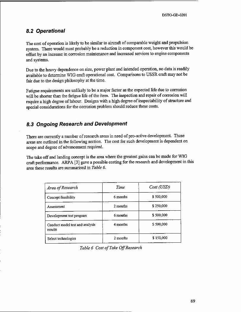
DSTO-GD-0201
8.2 Operational
The cost of operation is likely to be similar to aircraft of comparable weight and propulsion system. There would most probably be a reduction in component cost, however this would be offset by an increase in corrosion maintenance and increased services to engine components and systems.
Due to the heavy dependence on size, power plant and intended operation, no data is readily available to determine WIG craft operational cost. Comparisons to USSR craft may not be fair due to the design philosophy at the time.
Fatigue requirements are unlikely to be a major factor as the expected life due to corrosion will be shorter than the fatigue life of the item. The inspection and repair of corrosion will require a high degree of labour. Designs with a high degree of inspectability of structure and special considerations for the corrosion problem should reduce these costs.
8.3 Ongoing Research and Development
There are currently a number of research areas in need of pro-active development. These areas are outlined in the following section. The cost for such development is dependent on scope and degree of advancement required.
The take off and landing concept is the area where the greatest gains can be made for WIG craft performance. ARPA [3] gave a possible costing for the research and development in this area these results are summarised in Table 6.
Area of Research Time Cost (USD)
Concept feasibility 6 months $ 500,000
Assessment 2 months $ 250,000
Development test program 6 months $ 500,000
Conduct model test and analysis results
4 months $ 500,000
Select technologies 2 months $ 150,000
Table 6 Cost of Take Off Research
69
DSTO-GD-0201
9 CONCLUSION
These conclusions are based on a limited survey of the available literature and manufacturers' data. The authors have no direct experience in the design, manufacture or operation of WIG vehicles.
Practical applications of WIG craft have been actively researched and developed since the early 1960's, yet in that period these craft have not reached acceptance as mainstream transport vehicles in either civilian or military applications. No single reason for this failure to develop is obvious. While there are some technical difficulties to overcome, none of these appears insurmountable and while there are some operational limitations, they are not so severe that these craft could not find useful operational niches.
The major conflict for any new technology is between the cost of development and resultant gains of the technology. The development of WIG craft would rely on the developed craft providing transport solutions that are appreciably superior or appreciably different to other existing or potential forms of transport. To this time, potential private and government investors have not been convinced of the benefits of WIG craft development.
WIG craft have been championed on the basis that they are more efficient than equivalent aircraft and quicker than equivalent marine vessels. The efficiency argument is somewhat speculative. While theoretically an improvement in efficiency is gained by flying in ground effect, this efficiency is reduced by design compromises required of the WIG craft. Such compromises include strengthened hull structures, reduced aspect ratios and larger control forces. The degree to which total efficiency is improved can only be determined by the direct comparison of optimised designs of equivalent WIG and aircraft. Only through such a comparison would the value of the improved efficiency and the cost of gaining this efficiency be determined.
The speed advantage of WIG craft over conventional marine vessels may well provide the reason for considering WIG craft for particular applications. WIG craft can be developed to travel at significantly faster speeds than the equivalent marine vessels. There may well be applications for marine vessels where the speed of the vessel is the most critical specification. There are also disadvantages and limitations to their operation and a number of areas in which further research is required in order to build a practical vehicle.
The limitations of the vehicle are primarily concerned with sea state. Landing and take off of WIG craft is limited to relatively small sea states and cruise over high sea states, while possible, is relatively inefficient. Other disadvantages are primarily concerned with the operation of aircraft structures in marine environments. Along with the use of exposed engines, corrosion on load bearing light weight structures will demand a relatively high maintenance cost.
Stability and control, aerodynamics analysis and systems are all areas that have provided difficulties to the designers of WIG craft. These difficulties have been overcome by recent developments in the aviation field. It is also considered that the technology available in these fields is more than adequate for use on WIG craft.
70

DSTO-GD-0201
Research into take off aids has the potential to reduce the sea state limitations on WIG craft. This area of research is likely to provide the most important contributions to the reduction of these limitations. Other areas in which further research is required are propulsion, hull load determination and sensors. The use of exposed engines in the highly corrosive marine environment carries a high maintenance cost and reduced reliability. The accurate determination of hull loads in the takeoff and landing phases would lead to more efficient structural design. Increased safety and better cruise performance may well flow from accurate sensors detecting sea state, altitude and obstacles.
This research would primarily involve the adaptation of current technology to the special requirements of WIG craft. There are no apparent technological barriers to the successful design, manufacture and operation of WIG craft.
71

DSTO-GD-0201
10 BIBLIOGRAPHY
[I] Advanced Research Projects Agency, (1994) "Wingship Investigation - Volume 1 - Final Report", Advanced Research Projects Agency (ARPA) Report, 30 September 1994.
[2] Advanced Research Projects Agency, (1994) "Wingship Investigation - Volume 2 - Appendices", Advanced Research Projects Agency (ARPA) Report, 30 September 1994.
[3] Advanced Research Projects Agency, (1994) "Wingship Investigation - Volume 3 - Technology Roadmap", Advanced Research Projects Agency (ARPA) Report, 30 September 1994.
[4] Bogdanov, A. and Maskalik, A. (1996) "Some Results on the Civil Ekranoplans Certification Works" Ekranoplans and Very Fast Craft, Workshop Proceedings of, 1996, pp 177-185.
[5] Bogdanov, A. (1996) "Discussions on the Operational Aspects of WIG Craft at the IMO Sub-Committee on Safety of Navigation" Ekranoplans and Very Fast Craft, Workshop Proceedings of, 1996, pp 213 - 229.
[6] Bordonov, A. (1996) In the discussion to the paper by Kirillovikh, V. (1996) "Discussions on the Operational Aspects of WIG Craft at the MO Sub-Committee on Safety of Navigation" Ekranoplans and Very Fast Craft, Workshop Proceedings of, 1996, pp 213 - 229.
[7] Carter, A. (1961) "Effect of Ground Proximity on the Aerodynamic Characteristics of AR 1 Aerofoils With and Without End Plates", NASA TN D-970, October 1961.
[8] Carter, A., (1970) "Effects of Ground Proximity on the Longitudinal Aerodynamic Characteristics of an Unswept AR 10 Wing", NASA TN D-5662, February 1970.
[9] Fellows, J., Harner, M., Pickett, J. and Welch, M. (1996) "Airlift 2025: The First With the Most", Research Paper Presented to Air Force 2025, August 1996.
[10] Fischer, H. and Matjasic, K. (1996) "Some Thoughts About the Use of Lift-Off-Aids as One Condition for the Economic Operation of WIG Ships", Ekranoplans and Very Fast Craft, Workshop Proceedings of, 1996, pp 163-176.
[II] Heber, C. and Taylor, D. (1981) "The Power-Augmented Ram Wing-In-Ground Effect Concept as an Airborne Amphibious Quick Reaction Force", AIAA Paper 81-2077.
[12] Hooker, S., (1996) "Some Thoughts on the Commercialisation of Ekranoplans and Wingships" Ekranoplans and Very Fast Craft, Workshop Proceedings of, 1996, pp 272- 294.
[13] Hooker S. (1989) "A Review of Current Technical Knowledge Necessary to Develop Large Scale Wing-In-Surface Effect Craft", AIAA Paper 89-1497, 1989.
[14] Hooker, S. (1995) "Twenty First Century Shipping at Aircraft Speeds", Proceedings of a Workshop on Twenty-First Century Flying Ships, The University of New South Wales, November 1995, pp 178-232.
72

DSTO-GD-0201
[15] Jane's Surface Skimmers 1983
[16] Katzoff, S. and Sweberg, H. (1943) "Ground Effect on Downwash Angles and Wake Location", NACA R 738,1943.
[17] Kirillovikh, V. (1995)"Russian Ekranoplans", Proceedings of a Workshop on Twenty- First Century Flying Ships, The University of New South Wales, November 1995, pp 71-117.
[18] Kirillovikh, V. (1996) In the discussion to the paper by Bogdanov, A. "Discussions on the Operational Aspects of WIG Craft at the MO Sub-Committee on Safety of Navigation" Ekranoplans and Very Fast Craft, Workshop Proceedings of, 1996, pp 213-229.
[19] Leslie, J. (1996) "The Commercialisation of Sea Wing Ground Effect Vessels", Ekranoplans and Very Fast Craft, Workshop Proceedings of, 1996.
[20] Malyshev, M. (1995) "Experience of Using Ekranoplans in Russian Navy", Proceedings of a Workshop on Twenty-First Century Flying Ships, The University of New South Wales, November 1995, pp 233-244.
[21] Meeks, T. and Mantle, P. (1976) "The Advanced Naval Vehicle Concept" AIAA Paper 76-846.
[22] Prandolini, L. (1995) "Preface" to Proceedings of a Workshop on Twenty-First Century Flying Ships, The University of New South Wales, November 1995.
[23] Roskam, J., (1990) "Airplane Design - Part VIII", The University of Kansas.
[24] Rozhdestvensky,K. (1995) "Ekranoplans- Flying Ships of the Next Century", Proceedings of a Workshop on Twenty-First Century Flying Ships, The University of New South Wales, November 1995.
[25] Rozhdestvensky K. (1996) "Ekranoplans - The GEMs of Fast Water Transport" Trans ImarE, Vol 109, Part 1, pp 47-74.
[26] Sinitsyn, D. and Maskalik, A., (1996) "The Ekranoplan is a New Type of High Speed Water Transport Which Can be Used in All Seasons", Ekranoplans and Very Fast Craft, Workshop Proceedings of, 1996, pp .
[27] Sinitsyn, D., Maskalik, A. and Litinsky, L., (1996) "The Present Day State and Prospect for the Development of Commercial Ekranoplans", Ekranoplans and Very Fast Craft, Workshop Proceedings of, 1996, pp 163-176.
[28] Sinitsyn, D. and Maskalik, A., (1996) "Summary of the Construction of the First Commercial Ekranoplan' Amphistar' ", Ekranoplans and Very Fast Craft, Workshop Proceedings of, 1996.
[29] Staufenbiel, R. and Schlichting, U, (1988), "Stability of Airplanes in Ground Effect", Journal of Aircraft, Vol 25, No. 4, pp. 289-294.
[30] van Opstal, E. "Wing in Ground Effect Vehicles" World Wide Web Page 'http://www.io.tudelg.nl' at date January 14,1998.
73

DSTO-GD-0201
74

DSTO-GD-0201
11 GLOSSARY AND ABBREVIATIONS
AMSA Australian Maritime Safety Authority
AR See Aspect Ratio.
ARPA Advanced Research Projects Agency (USA, Formerly DARP A)
Aspect Ratio The aspect ratio is the ratio of the span to the chord for rectangular wings or the square of the span divided by the area of the wing.
Boundary The edge of a domain or surface.
CDBHC Central Design Bureau for Hydrofoil Craft (Former USSR)
eg/CG Centre of Gravity
Chord The distance from the leading edge to the trailing edge of a wing section.
COTS Commercial Of The Shelf
Dihedral The angle the lateral axis of a wing makes with the horizontal plane.
DoD Department of Defence
Drag (induced) Drag due to the generation of lift.
Drag (parasitic/profile) Drag due to skin friction turbulence and wake
Freestream Velocity
Ground Effect
ICAO
IGE
generation.
The relative velocity of an object moving through undisturbed air.
A phenomenon caused by the presence of a boundary altering the circulation around a lifting body.
International Civil Aviation Organisation
In Ground Effect.
75
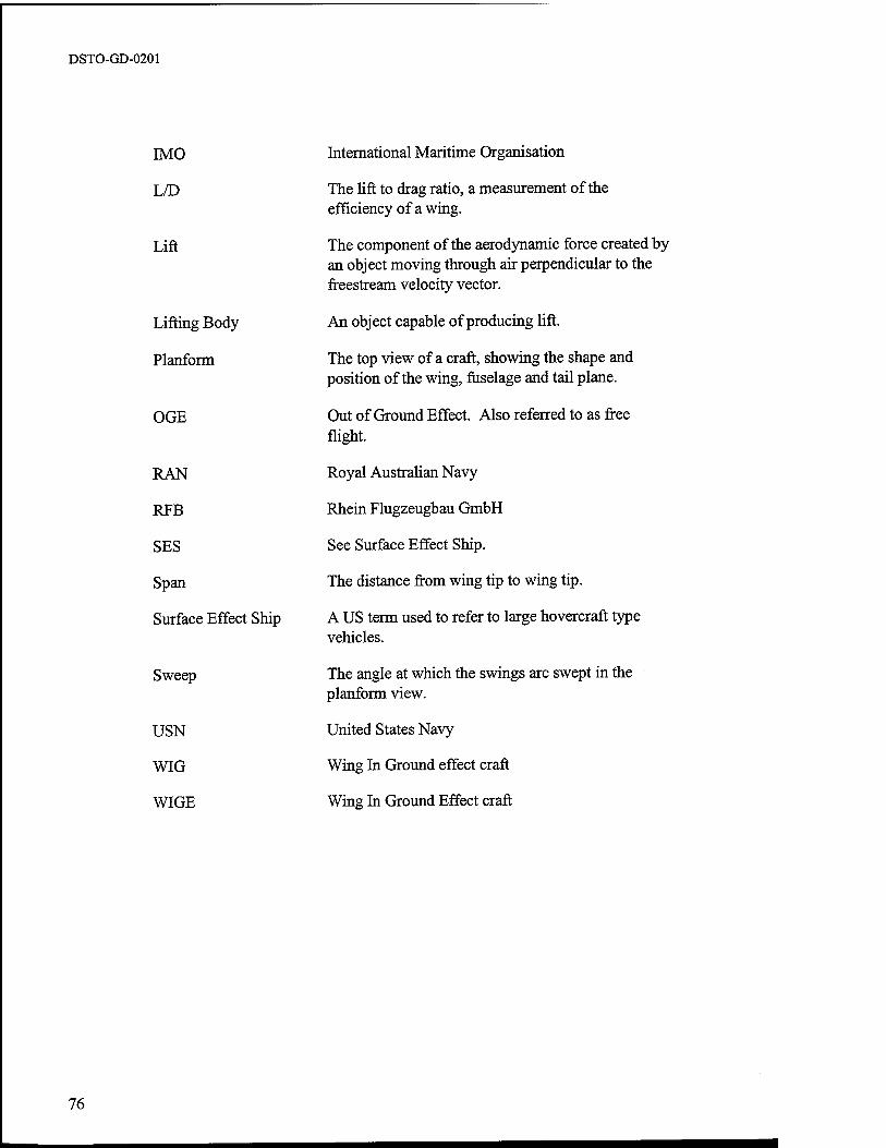
DSTO-GD-0201
IMO
L/D
Lift
Lifting Body
Planform
OGE
RAN
RFB
SES
Span
Surface Effect Ship
Sweep
USN
WIG
WIGE
International Maritime Organisation
The lift to drag ratio, a measurement of the efficiency of a wing.
The component of the aerodynamic force created by an object moving through air perpendicular to the freestream velocity vector.
An object capable of producing lift.
The top view of a craft, showing the shape and position of the wing, fuselage and tail plane.
Out of Ground Effect. Also referred to as free flight.
Royal Australian Navy
Rhein Flugzeugbau GmbH
See Surface Effect Ship.
The distance from wing tip to wing tip.
A US term used to refer to large hovercraft type vehicles.
The angle at which the swings are swept in the planform view.
United States Navy
Wing In Ground effect craft
Wing In Ground Effect craft
76
DISTRIBUTION LIST
Wing in Ground Effect Craft Review
Michael Halloran and Sean O'Meara
AUSTRALIA
DEFENCE ORGANISATION
TASK SPONSOR: Strategic Policy and Plans Director General Capability Analysis
S&T Program Chief Defence Scientist ] FAS Science Policy j* shared copy
AS Science Corporate Management J Director General Science Policy Development Counsellor Defence Science, London (Doc Data Sheet) Counsellor Defence Science, Washington (Doc Data Sheet) Scientific Adviser to MRDC Thailand (Doc Data Sheet) Scientific Adviser Policy and Command Navy Scientific Adviser Scientific Adviser - Army (Doc Data Sheet and distribution list only) Air Force Scientific Adviser Director Trials
Aeronautical and Maritime Research Laboratory Director
Chief of Maritime Platforms Division J. Cocking K. Gaylor (6 copies)
Author(s): The Sir Lawrence Wackett Centre for Aerospace Design Technology, Royal Melbourne Institute of Technology: Attention: Michael Halloran,
Sean O'Meara
DSTO Library Library Fishermens Bend Library Maribyrnong Library Salisbury (2 copies) Australian Archives Library, MOD, Pyrmont (Doc Data sheet only)

Capability Development Division Director General Maritime Development Director General Land Development (Doc Data Sheet only) Director General C3I Development (Doc Data Sheet only) Director General Aerospace Development (Doc Data Sheet only)
Army ABCA Office, G-l-34, Russell Offices, Canberra (4 copies) SO (Science), DJFHQ(L), MILPO Enoggera, Queensland 4051 (Doc Data Sheet
only) NAPOC QWG Engineer NBCD c/- DENGRS-A, HQ Engineer Centre Liverpool
Military Area, NSW 2174 (Doc Data Sheet only)
Intelligence Program DGSTA Defence Intelligence Organisation
Corporate Support Program (libraries) OIC TRS, Defence Regional Library, Canberra *US Defence Technical Information Center, 2 copies *UK Defense Research Information Centre, 2 copies *Canada Defence Scientific Information Service, 1 copy *NZ Defence Information Centre, 1 copy National Library of Australia, 1 copy
UNIVERSITIES AND COLLEGES
Australian Defence Force Academy Library Head of Aerospace and Mechanical Engineering
Senior Librarian, Hargrave Library, Monash University Librarian, Flinders University

OTHER ORGANISATIONS
NASA (Canberra) AGPS
OUTSIDE AUSTRALIA
ABSTRACTING AND INFORMATION ORGANISATIONS INSPEC: Acquisitions Section Institution of Electrical Engineers Library, Chemical Abstracts Reference Service Engineering Societies Library, US Materials Information, Cambridge Scientific Abstracts, US Documents Librarian, The Center for Research Libraries, US
INFORMATION EXCHANGE AGREEMENT PARTNERS Acquisitions Unit, Science Reference and Information Service, UK Library - Exchange Desk, National Institute of Standards and Technology, US
SPARES (5 copies)
Total number of copies: 56

UNCLASSIFIED
DEFENCE SCIENCE AND TECHNOLOGY ORGANISATION DOCUMENT CONTROL DATA
Z TITLE
Wing in Ground Effect Craft Review
4. AUTHOR(S)
Michael Halloran and Sean O'Meara
The Sir Lawrence Wackett Centre for Aerospace Design
Technology Royal Melbourne Institute of Technology
6a. DSTO NUMBER DSTO-GD-0201
8. FILE NUMBER 510/207/1027
6b. AR NUMBER AR-010-831
9. TASK NUMBER NAV 98/014
13. DOWNGRADING/DELIMITING INSTRUCTIONS
1. PRIVACY MARKING/CAVEAT (OF DOCUMENT)
3. SECURITY CLASSIFICATION (FOR UNCLASSIFIED REPORTS THAT ARE LIMITED RELEASE USE (L) NEXT TO DOCUMENT CLASSIFICATION)
Document Tide Abstract
(U) (U) (U)
5. CORPORATE AUTHOR
Aeronautical and Maritime Research Laboratory
PO Box 4331 Melbourne Vic 3001 Australia
6c. TYPE OF REPORT General Document
10. TASK SPONSOR DGCA
11. NO. OF PAGES 74
7. DOCUMENT DATE February 1999
1Z NO. OF REFERENCES 30
14. RELEASE AUTHORITY
Chief, Maritime Platforms Division
15. SECONDARY RELEASE STATEMENT OF THIS DOCUMENT
Approved for public release
OVERSEAS ENQUIRIES OUTSIDE STATED LIMITATIONS SHOULD BE REFERRED THROUGH DOCUMENT EXCHANGE CENTRE, DIS NETWORK OFFICE, DEFT OF DEFENCE, CAMPBELL PARK OFFICES, CANBERRA ACT 2600 16. DELIBERATE ANNOUNCEMENT
No Limitations
17. CASUAL ANNOUNCEMENT Yes
18. DEFTEST DESCRIPTORS
Ground effect machines, Ground effect (aerodynamics), Aircraft design, Naval aircraft, High speed flight
19. ABSTRACT It has long been recognised that flight close to a boundary surface is more aerodynamically efficient than flight in the freestream. This has led to the design and construction of craft specifically intended to operate close to the ground and fly 'in ground effect'. A great range of Wing in Ground effect craft (WIGs) have been manufactured ranging from 2 seat recreational vehicles to 500 tonne warcraft. Despite this WIGs have never enjoyed great commercial or military success.
The Maritime Platform Division of DSTO commissioned The Sir Lawrence Wackett Centre for Aerospace Design Technology to conduct a design review of WIG craft. This review considers all elements of WIG design and operation, including performance, limitations, control, stability, operational requirements, regulation, manufacture and technological risk. The review highlights the research required to overcome the weaknesses of WIG craft, the advantages that they may offer and the possible uses of WIG craft in the Australian military.
Page classification: UNCLASSIFIED


![R-OlO - DTIC · R-OlO A Study of the High Strain-Rate Behaviour of GRP Composites M.Z. Shah Khan, G. Simpson and M. Taylor DSTO-RR-0120 ] | APPROVED FOR PUBLIC RELEASE](https://img.pdfslide.us/doc/110x75/5f66da255d0a09207671c902/r-olo-dtic-r-olo-a-study-of-the-high-strain-rate-behaviour-of-grp-composites-mz.jpg)